WO2014099131A1 - Systems and methods for determining the cleanliness of a surface - Google Patents
Systems and methods for determining the cleanliness of a surface Download PDFInfo
- Publication number
- WO2014099131A1 WO2014099131A1 PCT/US2013/067175 US2013067175W WO2014099131A1 WO 2014099131 A1 WO2014099131 A1 WO 2014099131A1 US 2013067175 W US2013067175 W US 2013067175W WO 2014099131 A1 WO2014099131 A1 WO 2014099131A1
- Authority
- WO
- WIPO (PCT)
- Prior art keywords
- marking system
- carrier
- surface marking
- microspheres
- applicator
- Prior art date
Links
Classifications
-
- A—HUMAN NECESSITIES
- A61—MEDICAL OR VETERINARY SCIENCE; HYGIENE
- A61L—METHODS OR APPARATUS FOR STERILISING MATERIALS OR OBJECTS IN GENERAL; DISINFECTION, STERILISATION OR DEODORISATION OF AIR; CHEMICAL ASPECTS OF BANDAGES, DRESSINGS, ABSORBENT PADS OR SURGICAL ARTICLES; MATERIALS FOR BANDAGES, DRESSINGS, ABSORBENT PADS OR SURGICAL ARTICLES
- A61L2/00—Methods or apparatus for disinfecting or sterilising materials or objects other than foodstuffs or contact lenses; Accessories therefor
- A61L2/26—Accessories or devices or components used for biocidal treatment
- A61L2/28—Devices for testing the effectiveness or completeness of sterilisation, e.g. indicators which change colour
-
- G—PHYSICS
- G01—MEASURING; TESTING
- G01N—INVESTIGATING OR ANALYSING MATERIALS BY DETERMINING THEIR CHEMICAL OR PHYSICAL PROPERTIES
- G01N21/00—Investigating or analysing materials by the use of optical means, i.e. using sub-millimetre waves, infrared, visible or ultraviolet light
- G01N21/17—Systems in which incident light is modified in accordance with the properties of the material investigated
- G01N21/55—Specular reflectivity
-
- G—PHYSICS
- G01—MEASURING; TESTING
- G01N—INVESTIGATING OR ANALYSING MATERIALS BY DETERMINING THEIR CHEMICAL OR PHYSICAL PROPERTIES
- G01N21/00—Investigating or analysing materials by the use of optical means, i.e. using sub-millimetre waves, infrared, visible or ultraviolet light
- G01N21/17—Systems in which incident light is modified in accordance with the properties of the material investigated
- G01N21/47—Scattering, i.e. diffuse reflection
- G01N21/4738—Diffuse reflection, e.g. also for testing fluids, fibrous materials
-
- G—PHYSICS
- G01—MEASURING; TESTING
- G01N—INVESTIGATING OR ANALYSING MATERIALS BY DETERMINING THEIR CHEMICAL OR PHYSICAL PROPERTIES
- G01N21/00—Investigating or analysing materials by the use of optical means, i.e. using sub-millimetre waves, infrared, visible or ultraviolet light
- G01N21/84—Systems specially adapted for particular applications
- G01N21/88—Investigating the presence of flaws or contamination
- G01N21/94—Investigating contamination, e.g. dust
-
- B—PERFORMING OPERATIONS; TRANSPORTING
- B08—CLEANING
- B08B—CLEANING IN GENERAL; PREVENTION OF FOULING IN GENERAL
- B08B13/00—Accessories or details of general applicability for machines or apparatus for cleaning
-
- G—PHYSICS
- G01—MEASURING; TESTING
- G01N—INVESTIGATING OR ANALYSING MATERIALS BY DETERMINING THEIR CHEMICAL OR PHYSICAL PROPERTIES
- G01N21/00—Investigating or analysing materials by the use of optical means, i.e. using sub-millimetre waves, infrared, visible or ultraviolet light
- G01N21/17—Systems in which incident light is modified in accordance with the properties of the material investigated
- G01N21/55—Specular reflectivity
- G01N2021/551—Retroreflectance
-
- G—PHYSICS
- G01—MEASURING; TESTING
- G01N—INVESTIGATING OR ANALYSING MATERIALS BY DETERMINING THEIR CHEMICAL OR PHYSICAL PROPERTIES
- G01N2201/00—Features of devices classified in G01N21/00
- G01N2201/06—Illumination; Optics
- G01N2201/061—Sources
Definitions
- the present disclosure generally relates to systems and methods for determining the cleanliness of a surface, and particularly, for determining the cleanliness of an environmental surface, e.g., in a healthcare environment, using a unique surface marking system.
- the present disclosure also relates to surface marking systems and applicators for applying such marking systems to a surface of interest.
- microorganisms may be released onto surfaces (e.g., solid surfaces, equipment surfaces, clothing, etc.) from infected individuals or otherwise. Once a surface becomes contaminated with microorganisms, contact with the contaminated surface may easily and readily transfer microorganisms to other locations, such as another surface, an individual, equipment, food, or the like.
- surfaces e.g., solid surfaces, equipment surfaces, clothing, etc.
- contact with the contaminated surface may easily and readily transfer microorganisms to other locations, such as another surface, an individual, equipment, food, or the like.
- pathogenic microbes e.g., a surface becomes contaminated with microorganisms
- Such microbial contamination and/or transfer can be particularly troublesome because many of those who are present in such facilities (e.g., patients) are sick and may be immunologically compromised. Such individuals therefore have an increased risk of becoming sick from infection by the contaminating microbes.
- Contaminated surfaces in a hospital or healthcare setting have been found to contribute to the epidemic and endemic transmission of a variety of microorganisms or pathogens, including Clostridium difficile, vancomycin-resistant Enterococci (VRE), methycillin-resistent Stapholococcus aureus (MRSA), Acinetobacter baumannii, and Psuedomonas aeruginosa, as well as to the epidemic transmission of norovirus.
- pathogens have been associated with Healthcare Acquired Infections (HAIs). While environmental cleaning and disinfecting practices have become routine in such healthcare settings, there is still a need for a facile, structured, and robust monitoring system and method for monitoring an environment's cleanliness, and for monitoring the effectiveness of various cleaning and/or disinfecting procedures.
- Some existing monitoring systems employ a UV dye marking system in a transparent carrier.
- the glow from the UV dye can only be observed using an appropriate black light, such that the dyes are invisible to environmental services (EVS) staff during the cleaning procedures.
- EVS environmental services
- an EVS manager can apply the marking system to a number of surfaces in a patient room, an operating room, or the like, prior to cleaning. The surfaces that have been marked are unknown to the EVS cleaning staff. After cleaning, the EVS manager (e.g., shift manager) can return to the room with a black light to inspect the marked surfaces and establish whether the marking system was thoroughly removed from the surfaces of interest.
- an integrated environmental hygiene monitoring solution includes the use of a visual marking system.
- the surface marking systems of the present disclosure can be semi-quantitative and are used to determine if a surface has been adequately physically cleaned. Such surfaces can include environmental surfaces (e.g., walls, equipment, furniture, etc.) or skin surfaces (e.g., in monitoring hand washing of healthcare staff).
- the surface marking system can be a tool to measure the compliance of front-line environmental services (EVS) staff to various cleaning protocols. Visual inspection can be used to monitor the aesthetic appearance of a given environment.
- EVS front-line environmental services
- Visual inspection can be used to monitor the aesthetic appearance of a given environment.
- a useful and easy-to-use integrated monitoring solution for determining the cleanliness of an environment and/or for determining compliance with cleaning protocols can be important for EVS to properly manage cleaning a healthcare setting, such as a hospital.
- Surface marking systems of the present disclosure can serve as a surrogate for an environmental soil. They can be designed to be covert. Surface marking systems of the present disclosure employ retroreflective microspheres, rather than a UV dye, and therefore do not require a specialized light source to determine cleaning results.
- Some aspects of the present disclosure provide a method for determining the cleanliness of a surface.
- the method can include providing a surface marking system comprising a plurality of retroreflective microspheres dispersed in or dispensed on a carrier; applying the surface marking system to at least one discrete site on the surface; illuminating the at least one discrete site on the surface with visible light, after a cleaning; and detecting retroreflection emitted from the at least one discrete site on the surface in response to illuminating the at least one discrete site to determine the effectiveness of the cleaning of the surface.
- the applicator can include a container defining a reservoir; a surface marking system positioned in the reservoir, the surface marking system comprising a plurality of retroreflective microspheres dispersed in or dispensed on a carrier; and a dispenser configured to dispense the surface marking system from the reservoir.
- FIG. 1 illustrates a hospital room with a variety of environmental surfaces, and a plurality of discrete sites to which a surface marking system can be applied.
- FIG. 2 is a close-up schematic cross-sectional view of a discrete site of FIG. 1 that has been marked with a surface marking system according to one embodiment of the present disclosure, taken along line 2-2 of FIG. 1.
- FIG. 3 is a flow chart describing a method of determining the cleanliness of a surface according to one embodiment of the present disclosure.
- FIGS. 4-18 illustrate normalized pixel frequency versus pixel intensity for a variety of surface marking systems on a variety of surfaces, according to the Examples.
- FIG. 19 is a photomicrograph of the retroreflective microspheres of Example 3, as described in the Examples section.
- FIG. 20 is a photomicrograph of the microparticles of Comparative Example C3, as described in the Examples section.
- FIG. 21 is a perspective view of an applicator for a surface marking system according to one embodiment of the present disclosure.
- FIG. 22 is a perspective view of an applicator for a surface marking system according to another embodiment of the present disclosure.
- FIG. 23 is a perspective view of an applicator for a surface marking system according to another embodiment of the present disclosure.
- FIG. 24 is a perspective view of an applicator for a surface marking system according to another embodiment of the present disclosure.
- the present disclosure generally relates to visible-light-based surface marking systems, applicators for applying such surface marking systems to an environmental surface, and methods for determining the cleanliness of a surface and/or for determining compliance with cleaning protocols, e.g., by using such surface marking systems.
- Methods of the present disclosure can include providing such surface marking systems comprising retroreflective microspheres; applying the surface marking system to a discrete site on a desired surface, allowing a cleaning procedure to take place; illuminating the same discrete site after cleaning with a visible light; and detecting the amount of retroreflection emitted from the same discrete site in response to the illumination to determine the effectiveness of the cleaning process based on the amount of retroreflection that is produced from the surface marking system remaining at the discrete site on the surface. Detection can be performed visually and/or automatically, e.g., with a device that can emit visible light and possibly capture retroreflectivity data, such as brightness, retroreflection, intensity, images that can later be analyzed using appropriate software, etc.
- Retroreflective articles return incident light back towards the light source.
- Retroreflectivity in the present disclosure is provided by a plurality of transparent tiny beads or microspheres with a refractive index two times the refractive index of the medium from which the light source is incident. Under these conditions, the sphere surface behaves as a concave spherical mirror with the required curvature for retroreflection. However, the reflective index does not need to be twice that of the ambient medium to achieve retroreflection.
- the beads have a certain amount of spherical aberration, when the reflective index of the bead is at least 1.5 times that of ambient, there will be a radius from the centerline of the bead where a portion of the incident light is focused at the rear surface of the sphere giving rise to retroreflected light.
- Retroreflectivity can also be provided in the present disclosure by a plurality of tiny beads or microspheres (e.g., made of glass) that cooperate with a reflective agent, such as a coated layer of aluminum. Such coatings can be partial coatings on the outer surfaces of the beads. Incident light entering an exposed portion of a bead (e.g., uncoated) is focused by the bead onto the reflective agent. The reflective agent reflects the incident light back through the bead, causing the light to exit through the exposed portion of the bead in a direction opposite the incident direction.
- a reflective agent such as a coated layer of aluminum.
- the microspheres (or "beads") of the present disclosure are substantially spherical in shape to provide uniform and efficient retroreflection.
- the microspheres of the present disclosure are generally formed by being exposed to a spheroidization process, such as a melt-spheroidization process.
- the microspheres i.e., uncoated portions
- the microspheres preferably also are highly transparent to minimize light absorption so that a large percentage of incident light is retroreflected.
- the microspheres often are substantially colorless but may be tinted or colored in some other fashion.
- the microspheres may be made from glass, a non- vitreous ceramic composition, or a synthetic resin.
- microspheres are preferred because they tend to be harder and more durable and tend to have more suitable indices of refraction than microspheres made from synthetic resins.
- microspheres that may be useful in this invention are disclosed in the following United States patents: 1,175,224, 2,461,01 1, 2,726,161, 2,842,446, 2,853,393, 2,870,030, 2,939,797, 2,965,921, 2,992, 122, 3,468,681, 3,946, 130, 4,192,576, 4,367,919, 4,564,556, 4,758,469, 4,772,51 1, and 4,931,414. The disclosures of these patents are incorporated here by reference.
- the microspheres can have an average diameter of about 30 to 200 micrometers, in some embodiments, about 50 to 150 micrometers, and in some embodiments, about 10 to 100 micrometers. Microspheres smaller than the above ranges tend to provide lower levels of retroreflection, and microspheres larger than this range may impart an undesirably rough texture to the surface marking system. Microspheres used in the present disclosure can have a refractive index of about 1.5 to 3.0, in some embodiments, about 1.6 to 2.2, and in some embodiments, about 1.7 to 2.0.
- the microspheres can be coated with a specularly reflective material to enhance reflection.
- a specularly reflective material to enhance reflection.
- metals may be used to provide a specularly reflective metal layer. These include aluminum, silver, chromium, nickel, magnesium, gold, tin, nickel, tungsten, and the like, in elemental form.
- Aluminum and silver are preferred metals for use in the reflective layer because they tend to provide good retroreflective brightness.
- some of the metal may be in the form of the metal oxide and/or hydroxide.
- surface generally refers to any surface present in a given environment.
- Examples of such surfaces that can be present in healthcare facilities can include, but are not limited to, walls (including doors), floors, ceilings, drains, ducts (e.g., airducts), vents, toilet seats, handles, doorknobs, handrails, bedrails (e.g., in a hospital), countertops, tabletops, eating surfaces (e.g., trays, dishes, etc.), working surfaces, equipment surfaces, clothing, etc., and combinations thereof.
- Examples of surfaces can also include skin surfaces, such as surfaces on hands.
- the surface marking system can work using the flash from a camera (which also be used to capture before cleaning and after cleaning images). Such a detection system can also be convenient in quantifying the results, because flash photography can be used to measure the amount of reflected light from the beads and thus establish if that surface was cleaned properly.
- the surface marking system can further include a carrier in or on which the retroreflective microspheres can be dispersed or dispensed in order to dispense the retroreflective microspheres onto a desired surface in a contact deposition mode or a non-contact deposition mode, e.g., using at least one of liquid deposition, spraying, and dry transfer methods.
- One potential advantage for using visible light sources as opposed to specialized black light sources is that more convenient devices that may already be present in such a setting can be used for detection, as opposed to needing a specialized light source dedicated to the detection process that would not normally be present in that setting.
- the visible light source is the flash of a camera or other flash-photography-capable device
- the surface marking systems of the present disclosure are particulate in nature.
- One advantage of using a particulate or particle-based surface marking system can be that effective removal of the surface marking system can only be accomplished by physical means. This is in contrast to a UV dye- based system where simple dissolution may suffice for removal. Since physical removal of contamination can be key to the disinfection process, the surface marking systems and methods of the present disclosure provide a more robust challenge for the cleaning process.
- Another potential advantage of using the particle-based surface marking system over a UV-dye-based system is that the light emitted from the particle based system is point-like, and not a uniform glow as in the UV-dye-based systems, which can effectively provide a higher signal-to-noise ratio when measuring light output during detection.
- the point-like nature of the emitted light lends itself to analysis based on enumerating or counting the presence of discrete objects on the marked surface as a measurement of cleanliness. This is analogous to, for example, microbiological culture based methods where bacteria are enumerated on the surface of culture plates in order to quantify the concentration of a bacterial sample.
- the retroreflective microspheres can be suspended in, dispersed in and/or dispensed on a carrier.
- the carrier is a solvent
- the quick-drying carriers can be particularly useful.
- the carrier can be a thin layer of adhesive that will also require physical removal during the cleaning process.
- the carrier has two primary characteristics. First, the carrier does not significantly impede the cleaning process. That is, the carrier does not significantly increase the amount of time that one would need to wait prior to cleaning the marked room (e.g., quick-drying if the carrier is a liquid). Second, the carrier is generally designed to provide a challenge for removal that mimics an environmental soil (or skin soil) typical of the environment (or body part).
- FIG. 1 illustrates an exemplary hospital room 10 comprising a bed 12 having bedrails 14, a tray 16, one or more walls 18, a sink 20, a countertop 22, a cupboard 24, a paper towel dispenser 26, and a chair 28 having an armrest 30.
- the above items shown in the hospital room 10 are shown by way of example only to demonstrate a variety of items having surfaces to be cleaned in a hospital cleaning protocol. Surfaces on these items can be marked using surface marking systems of the present disclosure, cleaned according to a cleaning protocol appropriate for the given environment, and monitored using the methods of the present disclosure.
- a variety of discrete marking sites 50 are shown in FIG. 1 that can be marked using surface marking systems of the present disclosure and monitored using methods of the present disclosure.
- discrete sites 50 are shown on a bedrail 14, on a wall 18, on the countertop 22, on the cupboard 24, on the paper towel dispenser 26, and on the armrest 30 of the chair 28. While the discrete sites 50 are shown on surfaces in a hospital room, it should be understood that in some embodiments, the surface marking system 60 can be used to monitor hand hygiene and be used on skin as well.
- FIG. 2 illustrates a surface marking system 60 according to one embodiment of the present disclosure.
- the surface marking system 60 includes a carrier 62, and a plurality of retroreflective microspheres 64 dispersed in or dispensed on the carrier 62.
- the retroreflective microspheres 64 can include a base material 66 formed of any of the above-described materials or combinations thereof, and a coating 68, as described above.
- the coating 68 is illustrated as a partial coating over the base material 66 of each microsphere 64.
- the microspheres 64 may end up randomly oriented and distributed in or on the carrier 62, and ultimately, on the surface of interest. In such cases, at least enough of the microspheres 64 will end up oriented such that incident light can enter an exposed portion of a microspheres 64 and be reflected off the reflective coating 68 on the rear surface of the microsphere, back toward the light source, as illustrated by arrow L in FIG. 2.
- the carrier 62 can be in a variety of forms and include a variety of materials.
- the carrier 62 can include, but is not limited to, one or more solvents that are at least as volatile as water at room temperature, e.g., 25 degrees C (and in some embodiments, are more volatile than water at room temperature), one or more surfactants, one or more propellants (e.g., chlorofluorocarbons (CFCs), hydrofluoroalkanes (HFAs), etc.), one or more polymeric binders, or combinations thereof.
- one or more solvents that are at least as volatile as water at room temperature, e.g., 25 degrees C (and in some embodiments, are more volatile than water at room temperature
- one or more surfactants e.g., chlorofluorocarbons (CFCs), hydrofluoroalkanes (HFAs), etc.
- propellants e.g., chlorofluorocarbons (CFCs), hydrofluoroalkanes (H
- the carrier 62 can include a non-solid phase that evaporates quickly (e.g., that is at least as volatile as water at room temperature, and in some embodiments, more volatile than water at room temperature), and if any solid components are present in the carrier 62, the solid components are water-soluble.
- Surface marking systems employing such carriers 62 would dry relatively quickly but would also be easily removed by standard cleaning (e.g., water-based) procedures and products, such that the surface marking system does not significantly impede cleaning procedures or present unnecessary cleaning challenges once dried onto a surface of interest.
- solvents that are at least as volatile as water at room temperature include, but are not limited to, water, alcohols (e.g., methanol, ethanol, propanol, isopropyl alcohol, etc.), acetone, methyl acetate, ethyl acetate, other suitable solvents that are at least as volatile as water at room temperature, or a combination thereof.
- alcohols e.g., methanol, ethanol, propanol, isopropyl alcohol, etc.
- acetone methyl acetate
- ethyl acetate ethyl acetate
- Suitable surfactants can include, but are not limited to, anionic surfactants (e.g., dioctyl sodium sulfosuccinate, perfluorooctanesulfonate (PFOS), perfluorobutanesulfonate, linear alkylbenzene sulfonates), cationic surfactants (cetyl trimethylammonium bromide (CTAB) cetyl trimethylammonium chloride (CTAC) cetylpyridinium chloride (CPC), benzalkonium chloride (BAC), benzethonium chloride (BZT), 5-bromo-5-nitro- l,3-dioxane, dimethyldioctadecylammonium chloride, dioctadecyldimethylammonium bromide (DODAB), etc.); nonionic surfactants (e.g., polyoxyethylene glycol alkyl ethers , octaethylene glycol mono
- the retroreflective microspheres 64 can be randomly distributed in or on the carrier 62.
- the carrier 62 can be water-soluble and can enable the surface marking system 60 to be temporary, removable with normal or typical cleaning procedures for a given environment or body surface, etc.
- the surface marking system 60 is non-toxic, such that the retroreflective microspheres 64 and the carrier 62 are formed of non-toxic materials that do not present a hazard.
- the microspheres 64 When the microspheres 64 are dispersed in a liquid volumetric carrier, the microspheres 64 can be dispersed in the carrier 62 at a concentration of at least about 1000 (1 X 10 3 ) microspheres 64 per mL of carrier 62, in some embodiments, at a concentration of at least about 10,000 (1 X 10 4 ), and in some embodiments, at a concentration of at least about 50,000 (5 X 10 4 ).
- the microspheres 64 can be dispersed in the carrier 62 at a concentration of no greater than about 1,000,000 (1 X 10 6 ) microspheres 64 per mL of carrier 62, in some embodiments, at a concentration of no greater than about 500,000 (5 X 10 5 ), and in some embodiments, at a concentration of no greater than about 100,000 (1 X 10 5 ). In some embodiments, the microspheres 64 can be dispersed in the carrier 62 at a concentration ranging from 1000-1,000,000 microspheres 64 per mL of carrier 62.
- the carrier 62 can include an adhesive or an adhesive layer, and the microspheres 64 can be dispensed onto a surface of the adhesive, the adhesive being suitable for mimicking environmental (or skin) soil in a given environment (or body part).
- an adhesive can include, e.g., a double-side adhesive to adhere to a surface and hold the microspheres 64 in place on the surface sufficiently and reliably.
- such an adhesive carrier can be dispensed from a tape dispenser that separates a release liner from the adhesive and lays the adhesive down on a surface while also dispensing the retroreflective microspheres on the adhesive.
- Adhesive carriers can include, but are not limited to, pressure sensitive adhesives including ones based on polyacrylates, natural rubber, synthetic rubber, spray adhesives, repositionable adhesives, and combinations thereof.
- the microspheres 64 can be dispensed on the carrier 62 at a concentration of at least about 100 (1 X 10 2 ) microspheres 64 per cm 2 of carrier 62, in some embodiments, at a concentration of at least about 1 ,000 (1 X 10 3 ), and in some embodiments, at a concentration of at least about 5,000 (5 X 10 3 ).
- the microspheres 64 can be dispersed in the carrier 62 at a concentration of no greater than about 100,000 (1 X 10 5 ) microspheres 64 per cm 2 of carrier 62, in some embodiments, at a concentration of no greater than about 50,000 (5 X 10 4 ), and in some embodiments, at a concentration of no greater than about 10,000 (1 X 10 4 ). In some embodiments, the microspheres 64 can be dispensed on the carrier 62 at a concentration ranging from 100- 100,000 microspheres 64 per cm 2 of carrier 62.
- One potential advantage of the surface marking systems employed in methods of the present disclosure is that the brightness and conspicuity of the surface marking systems of the present disclosure are superior to other existing marking systems.
- the Examples section below compares examples of surface marking systems of the present disclosure with a comparative microparticle system and existing UV-dye -based marking systems.
- a quality factor Q and a 'gain ratio' for the surface marking system can be obtained.
- an intensity histogram can be created, e.g., which plots pixel frequency as the Y axis vs. pixel intensity as the X-axis.
- the intensity can also be approximated as representing a "lightness” value L present in a Lab color space with dimension L for lightness and "a" and "b” for the color-opponent dimensions, based on nonlinearly compressed CIE XYZ color space coordinates.
- the pixel frequency (or quantity) therefore provides the number of pixels with a given pixel intensity.
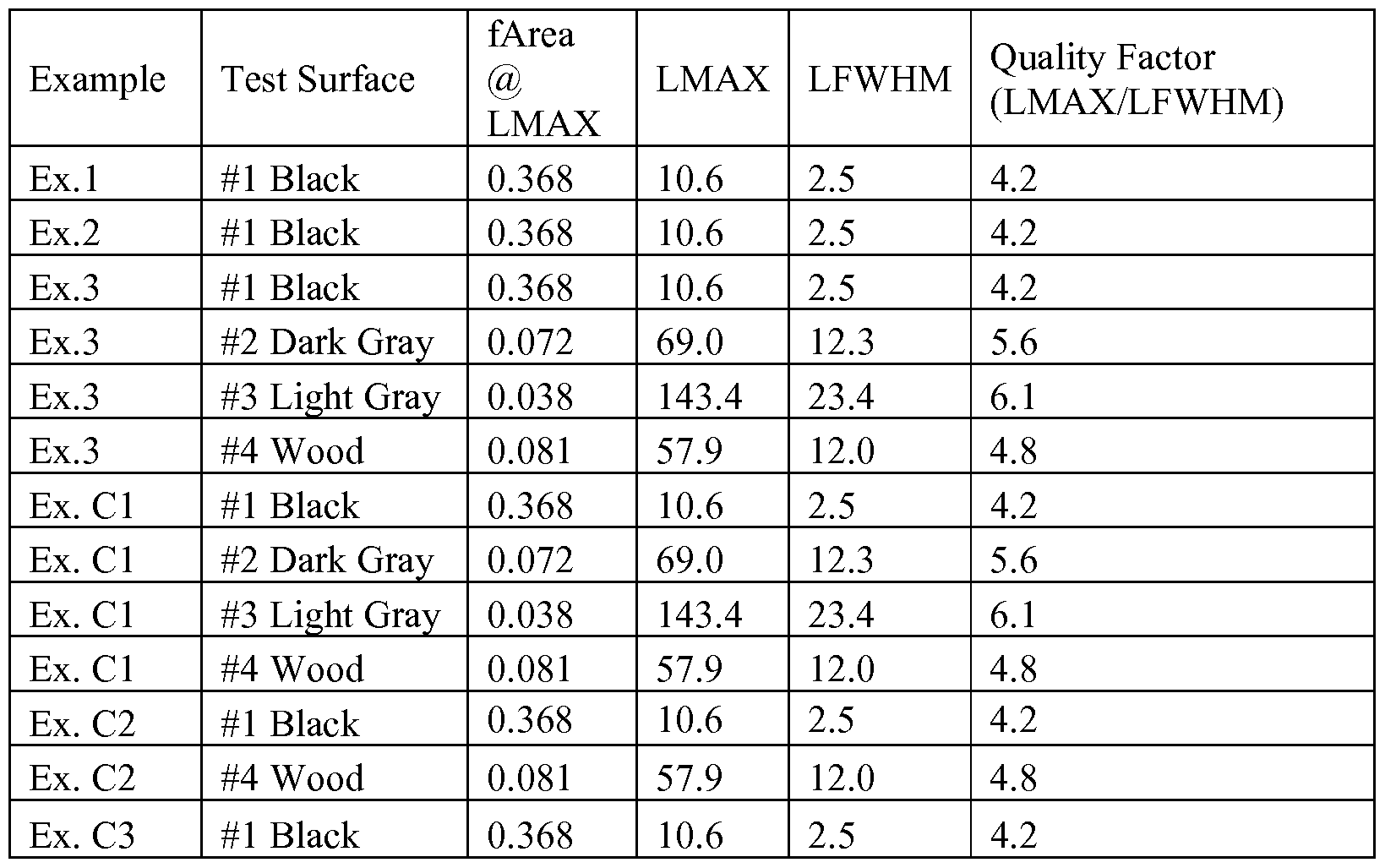
- Such pixel intensity histograms can then be curve-fit (e.g., as described in the Examples section), and three parameters can be extracted: L M AX, L FWH M, and fArea@L M A - LMAX is the pixel intensity or "lightness" at the maximum normalized pixel frequency for the fit function.
- fArea@L M A is the normalized pixel frequency value corresponding to LMAX- L FWH M is the pixel intensity full width at a normalized pixel frequency value that is exactly half of fArea@L M A -
- a quality factor Q L M AX/LFWHM can be calculated, for the non- illuminated state of the system (Qo ff ) as well as for the illuminated state of the system (Qo n ).
- the Q factors describe the distribution of pixel intensity across the entirety of the surface mark.
- High Q factors are representative of surface marks where there is a significant majority of pixels within a very narrow distribution (small L FWH M) about a relatively high center intensity (large L M AX).
- LOW Q factors describe the opposite condition: surface marks where the significant majority of pixels have intensities spread out over a broad distribution (Large L FWH M) centered about a relatively low intensity (small L M AX).
- the 'gain ratio' the ratio of Qo n to Qo ff (the 'gain ratio')
- This gain ratio describes the magnitude by which the surface mark becomes apparent to an observer when the illuminating source is turned on.
- the surface marking system 60 can be substantially invisible or at least inconspicuous (i.e., covert) to the EVS cleaning staff, and in some embodiments, the surface marking system 60 can be visible to the EVS cleaning staff.
- a transparency ratio for the surface marking system in order to quantify and characterize the visibility or covertness of the surface marking system, can be obtained.
- the ratio of Qo ff to the Q factor determined for the non-marked and non- illuminated surface is representative of the transparency of the surface mark on a given surface.
- This 'transparency ratio' is indicative of how "covert" the marked surface is to a given observer.
- Approaching a transparency ratio of 1.0 maximizes the covertness of the system.
- FIG. 3 illustrates a method 100 according to one embodiment of the present disclosure.
- the method 100 can include a first step 102 which includes applying a surface marking system to one or more discrete sites (e.g., the discrete sites 50 of FIG. 1) on a surface of interest.
- the method of application can be dependent on the type of surface marking system that is employed.
- at least one of liquid deposition e.g., employing a roller ball
- Spraying and foaming can be examples of non-contact application modes
- liquid deposition can be an example of contact application modes.
- non-contact application modes can be preferred to allow an applicator to be reused. Applicators employing contact methods of application may need to be re-sterilized or discarded after a single use.
- the method 100 further includes a second step 104 of cleaning the surface.
- the second step 104 may not necessarily form a portion of the methods of the present disclosure, because the cleaning step may be performed by a different entity than the entity performing the remaining steps of the method 100.
- management may perform most of the steps of the method 100, and EVS cleaning staff may perform the cleaning step 104.
- the surface marking system can be covert, the discrete sites that have been marked with the surface marking system can be unknown to the cleaning entity (e.g., EVS staff), and/or the monitoring methods of the present disclosure may be unknown to the cleaning entity.
- the method 100 further includes a third step 106 that includes illuminating the discrete sites that were marked in the first step 102 with a visible light.
- a variety of light sources can be used to illuminate the discrete sites with visible light, including, but not limited to, at least one of a flashlight, a lamp, a lantern, a camera, a smart phone, a smart phone camera, a tablet computer, a tablet computer camera, other portable devices with integrated flash cameras, other suitable visible light sources, and a combination thereof.
- the method 100 can further include a fourth step 108 which includes detecting emitted retroreflection from the discrete sites in response to illuminating the discrete sites. Based on the amount of retroreflected light that is emitted from each discrete site, the cleanliness of a surface can be determined and/or compliance with a cleaning protocol can be ascertained. As mentioned above, detection can be performed visually or with a detection device.
- detection devices can be employed with the methods of the present disclosure, including, but not limited to, at least one of a camera (e.g., any camera that is capable of flash photography; cameras used in conjunction with an external flash or a separate flashlight; etc.), other suitable detection devices, and combinations thereof.
- FIGS. 21-23 illustrate exemplary applicators of the present disclosure.
- FIG. 21 illustrates an applicator 150A that can be used to spot, dab, paint, foam, or the like as means of applying a surface marking system to an environmental surface.
- the applicator 150A includes a container 152A that includes or defines a reservoir 154A configured to house a surface marking system 60A comprising retroreflective microspheres 64A dispersed in a carrier 62A (e.g., a liquid volumetric carrier). Any of the above-described liquid carriers and retroreflective microspheres can be employed.
- the applicator 150A further includes a dispenser or means for dispensing 156A configured to dispense the surface marking system 60A from the reservoir 154A (e.g., via the dispenser 156A).
- the dispenser 156A can be coupled to the container 152A and positioned in fluid communication with the reservoir 154A of the container 152A, such that the surface marking system 60A can be passed through the dispenser 156A to apply the surface marking system 60A to a surface.
- the sides of the container 152A can be squeezed to force the surface marking system 60A through the dispenser 156A.
- the dispenser 156A can be configured to spot, dab, paint, foam, or the like, or combinations thereof, to apply the surface marking system 60A to a surface.
- the dispenser 156A can include a porous substrate that can be sized to pass the carrier 62A and the retroreflective microspheres 64A therethrough.
- the dispenser 156A can include a sponge, a foam, a swab, a brush, a dabber, a filter membrane, a screen, or the like, or combinations thereof.
- FIG. 22 illustrates an applicator 150B that can be used to spray, squirt, foam and/or atomize as means of applying a surface marking system to an environmental surface.
- the applicator 150B includes a container 152B that includes or defines a reservoir 154B configured to house a surface marking system 60B comprising retroreflective microspheres 64B dispersed in a carrier 62B (e.g., a liquid volumetric carrier). Any of the above-described liquid carriers and retroreflective microspheres can be employed.
- the applicator 150B further includes a dispenser or means for dispensing 156B configured to dispense the surface marking system 60B from the reservoir 154B.
- the dispenser 156B can include a nozzle 158 that is in fluid communication with the reservoir 154B.
- the nozzle 158 is shown as including a pump spray nozzle, but it should be understood that a variety of nozzles (e.g., aerosol, or the like) can instead be employed.
- FIG. 23 illustrates an applicator 150C that can be used to apply a surface marking system to an environmental surface.
- the applicator 150C includes a container 152C that includes or defines a reservoir 154C configured to house a surface marking system 60C comprising retroreflective microspheres 64C dispensed on a carrier 62C (e.g., an adhesive layer). Any of the above-described adhesive or two-dimensional carriers and retroreflective microspheres can be employed.
- the applicator 150C further includes a dispenser or means for dispensing 156C configured to dispense the surface marking system 60C from the reservoir 154C.
- such an adhesive carrier 62C can be dispensed from the applicator 150C, which is shown by way of example only as being a tape dispenser and means for separating a release liner (or backing) 165C from the adhesive carrier 62C, such that the applicator 150C lays the adhesive carrier 62C down on a desired surface.
- the retroreflective microspheres 64C can simultaneously be dispensed onto the adhesive carrier 62C, or the microspheres 64C can be dispensed on the adhesive carrier 62C prior to being loaded into the applicator 150C.
- FIG. 24 illustrates an applicator 150D that can be used to apply a surface marking system to an environmental surface.
- the applicator 150D includes a container 152D that includes or defines a reservoir 154D configured to house a surface marking system 60D comprising retroreflective microspheres 64D dispersed in a carrier 62D (e.g., a liquid volumetric carrier). Any of the above- described liquid carriers and retroreflective microspheres can be employed.
- the applicator 150D further includes a dispenser or means for dispensing 156D configured to transfer the surface marking system 60D from the reservoir 154D to a surface of interest.
- the container 152D can include a lid or cover 153D removably coupled to a base 155D, and the dispenser 156D can be coupled to the lid 153D, such that when the lid 153D is removed from the base 155D, the lid 153D can be grasped like a handle, and the surface marking system 60D can be applied to a surface of interest using the dispenser 156D.
- the applicator 150D and particularly the container 152D, are within the scope of the present disclosure.
- the dispenser 156D is shown as including a brush 170; however, it should be understood that in some embodiments, the dispenser 156D can include a sponge, a foam, a swab, a dabber, etc., or combinations thereof. In some embodiments, the dispenser 156D can include a porous substrate.
- FIGS. 21-24 are illustrated as a separate embodiment for clarity in illustrating a variety of features of the applicators of the present disclosure. However, it should be understood that any combination of elements and features of any of the embodiments illustrated in the figures and described herein can be employed in the applicators of the present disclosure.
- Embodiment 1 is a method for determining the cleanliness of a surface, the method comprising: providing a surface marking system comprising a plurality of retroreflective microspheres dispersed in or dispensed on a carrier;
- Embodiment 2 is the method of embodiment 1, wherein detecting includes visually detecting.
- Embodiment 3 is the method of embodiment 1 or 2, wherein the surface is an environmental surface.
- Embodiment 4 is the method of any of embodiments 1-3, wherein the at least one discrete site on the surface is unknown to environmental services staff.
- Embodiment 5 is the method of any of embodiments 1 -4, wherein the surface marking system is covert.
- Embodiment 6 is the method of any of embodiments 1-5, wherein the plurality of retroreflective beads are randomly distributed in or on the carrier.
- Embodiment 7 is the method of any of embodiments 1 -6, wherein the surface marking system is comprised of non-toxic material.
- Embodiment 8 is the method of any of embodiments 1 -7, wherein the carrier is water-soluble.
- Embodiment 9 is the method of any of embodiments 1-8, wherein applying the surface marking system includes non-contact application.
- Embodiment 10 is the method of any of embodiments 1 -9, wherein applying the surface marking system includes spraying.
- Embodiment 1 1 is the method of any of embodiments 1-10, wherein applying the surface marking system includes foaming.
- Embodiment 12 is the method of any of embodiments 1-1 1, wherein applying the surface marking system includes dry transfer.
- Embodiment 13 is the method of any of embodiments 1-12, wherein applying the surface marking system includes contact application.
- Embodiment 14 is the method of any of embodiments 1-13, wherein applying the surface marking system includes liquid deposition.
- Embodiment 15 is the method of any of embodiments 1- 14, wherein each of the plurality of retroreflective microspheres is at least partially coated with a reflective coating.
- Embodiment 16 is the method of any of embodiments 1-15, wherein the plurality of retroreflective microspheres are dispersed in the carrier to a concentration of no greater than about 1 X 10 6 microspheres/mL of the carrier.
- Embodiment 17 is the method of any of embodiments 1-16, wherein the plurality of retroreflective microspheres are dispensed on the carrier to a concentration of no greater than about 1 X 10 5 microspheres/cm 2 of the carrier.
- Embodiment 18 is the method of any of embodiments 1-17, wherein the plurality of retroreflective microspheres includes an average diameter of 10 to 100 micrometers.
- Embodiment 19 is the method of any of embodiments 1-18, wherein the carrier includes at least one of a surfactant, a polymeric binder, an adhesive layer, and a combination thereof.
- Embodiment 20 is an applicator for applying a surface marking system, the applicator comprising:
- a container defining a reservoir
- the surface marking system positioned in the reservoir, the surface marking system comprising a plurality of retroreflective microspheres dispersed in or dispensed on a carrier;
- a dispenser configured to dispense the surface marking system from the reservoir.
- Embodiment 21 is the applicator of embodiment 20, wherein the dispenser includes a porous substrate.
- Embodiment 22 is the applicator of embodiment 20 or 21 , wherein the dispenser includes at least one of a sponge, a foam, a swab, a brush, a dabber, or a combination thereof.
- Embodiment 23 is the applicator of any of embodiments 20-22, wherein the dispenser includes a nozzle.
- Embodiment 24 is the applicator of any of embodiments 20-23, wherein the carrier includes an adhesive, and wherein the container includes a tape dispenser.
- Embodiment 25 is the applicator of any of embodiments 20-24, wherein the carrier includes a solvent that is at least as volatile as water at room temperature..
- Embodiment 26 is the applicator of any of embodiments 20-25, wherein the carrier includes an alcohol.
- Example 1-3 Six different marker systems were evaluated - three Examples (Examples 1-3) of surface marking systems of the present disclosure employing visible-light-based systems and retroreflective microspheres, two Comparative Examples (CI and C2) employing UV (fluorescent)-based marking systems, and one Comparative Example (C3) employing a visible-light-based system and microparticles (i.e., that were not formed into microspheres).
- Example 1 was prepared with retroreflective microspheres, designated "W” beads, which were formed general glass recycle untreated microspheres with particle size less than 49 microns.
- Example 2 was prepared with retroreflective microspheres, designated "Y" Beads, which were finished chromium treated microspheres with the following size distribution:
- Example 3 was prepared with retroreflective microspheres designated "Z" beads, which were finished chromium treated microspheres with the size distribution detailed in Table 2.
- FIG. 19 is a photomicrograph of the Z beads, taken at 20X, with a digital color camera microscope: Leica DFC360 FX 1 1547002, available from Leica Microsystems CMS GmbH of Wetzlar, Germany.
- Comparative Example C 1 was trade name GLO GERM, a white emulsion available from the Glo Germ Company of Moab, Utah as the product MINI GEL in a 2 ounce bottle (MG20).
- Comparative Example C2 was trade name DAZO Fluorescent Marking System available from
- Comparative Example C3 was prepared with microparticles, which were milled glass recycle untreated unformed particles with particle size less than 49 microns.
- FIG. 20 is a photomicrograph of the microparticles of Comparative Example C3, taken at 20X, with a digital color camera microscope: Leica DFC360 FX 1 1547002, available from Leica Microsystems CMS GmbH of Wetzlar, Germany.
- Test Surface #1 was a black colored textured plastic.
- Test Surface #2 was a dark grey colored FORMICA brand surface.
- Test Surface #3 was a light grey colored FORMICA brand surface.
- Test Surface #4 was a finished (stained and varnished) natural cherry wood surface.
- UV markers Comparative Examples C1-C2 were used "as is” according to manufacturer's instructions (shaken before used).
- the retroreflective microspheres of Examples 1-3, and the microparticles of Comparative Example C3 were prepared as suspensions in isopropyl alcohol (IP A) at a concentration of 0.5 grams of microspheres/particles per 25 mL of IPA.
- the digital photographs were transferred as jpg files into SigmaScan V5.0 (available from Systat Software Inc.) and then the surface area to be analyzed was selected to generate an intensity histogram using the software.
- the histograms were a plot of Pixel Frequency as the Y axis vs.
- Pixel Intensity as the X-axis, where the Intensity is a relative number between zero to 256. Where zero represents black or minimum lightness and 256 represents maximum white or maximum lightness.
- the Intensity can also be approximated as representing a "Lightness" value L present in a Lab color space with dimension L for lightness and "a" and "b" for the color-opponent dimensions, based on nonlinearly compressed CIE XYZ color space coordinates.
- the pixel frequency (or quantity) therefore provides the number of pixels with a given pixel intensity.
- the histograms were further processed by normalizing the pixel frequency values to a total of 1.0 for each graph, so that appropriate overlays of different photo data could be placed in the same histogram, such as the background measure, the flash "on” and the flash "off photos. The same was done for the UV light on and UV light off photos.
- the normalized processed histograms are shown in Figures 4-16 for the various Examples and Comparative Examples on the different Test Surfaces.
- Example 1 (FIG. 4) & Comparative Example C3 (FIG. 5) on Test Surface #1 (Black)
- Example 2 (FIG. 6) & Example 3 (FIG. 7) on Test Surface #1 (Black)
- Example 3 (FIG. 10) and Comparative Example CI (FIG. 1 1) on Test Surface #2 (Dark Grey)
- L M AX, L FWH M, and fArea@LMA - L M AX is in the range from 0 (black) to 256 (white) and is the pixel intensity or "lightness" at the maximum normalized pixel frequency for the fit function.
- this L MAX is the same as the Pixel Intensity at max frequency, described above and reported in Tables 4-16.
- the L MAX for a curve fit is based on the applied curve function and will not always be equivalent to the raw data value for Pixel Intensity at max frequency.
- FIGS. 17 and 18 graphically illustrate the curve fitting process applied to the data sets and the results obtained.
- FIG. 17 uses the data set also presented in FIG. 7 for the Flash On and Flash Off data of Example 3 on Test Surface #1 (black).
- FIG. 18 uses the data set also presented in FIG. 8 for UV Light On and UV Light Off data of Comparative Example 1 on Test Surface #1 (black).
- FIGS. 17 and 18 graphically show the curve fit lines, as well as vertical lines which identify L M AX and L FW HM-
- Example 2 performed in similar manner to the other visible light, non-UV, particle- or bead-based samples (Example 1, Example 3, and Comparative Example 3) when not illuminated, on Test Surface #1.
- Q L M AX/L F WHM- Quality factors for both the non-illuminated state of the system, Q 0 fr as well as for the illuminated state of the system, QQstand were calculated.
- the Q factors described the distribution of pixel intensity across the entirety of the surface mark.
- High Q factors were representative of surface marks where there is a significant majority of pixels within a very narrow distribution (small L FW HM) about a relatively high center intensity (large LMAX) and are indicative of a surface marking systems which are easy to see with the naked eye because they are very bright.
- the ratio of Qo n to Qo ff was calculated for each data set of marker system on a test surface. This ratio of Qo n / Qo ff was called the Quality Factor Gain Ratio (QFGR) and was used to represent the intensity gain for the system when it transitioned from the non-illuminated to the illuminated state. This gain describes the magnitude by which the surface mark becomes visually apparent to an observer when the illuminating source (visible light or UV) is projected onto the marking system.
- QFGR Quality Factor Gain Ratio
- the ratio of Qo ff to QBackground was calculated for each data set of marker system on a test surface and is representative of the visual transparency of the surface mark on a given surface.
- the Q factor determined for the non-marked and non- illuminated surface is QBackground- This Transparency Ratio of Qo ff / QBackground is indicative of how "covert" the marked surface is to a given observer. Approaching a transparency ratio of 1.0 maximizes the covertness of the system.
- Table 13 Quality Factor Gain Ratios and Transparency Ratios
Abstract
Description


Claims
Priority Applications (6)
| Application Number | Priority Date | Filing Date | Title |
|---|---|---|---|
| US14/652,831 US9839712B2 (en) | 2012-12-21 | 2013-10-29 | Systems and methods for determining the cleanliness of a surface |
| EP13795028.3A EP2936121A1 (en) | 2012-12-21 | 2013-10-29 | Systems and methods for determining the cleanliness of a surface |
| CN201380067634.2A CN104884943B (en) | 2012-12-21 | 2013-10-29 | System and method for determining the cleannes on surface |
| BR112015015056A BR112015015056A2 (en) | 2012-12-21 | 2013-10-29 | systems and methods for determining the cleanliness of a surface |
| JP2015549378A JP2016509203A (en) | 2012-12-21 | 2013-10-29 | System and method for determining surface cleanliness |
| US15/807,197 US20180064837A1 (en) | 2012-12-21 | 2017-11-08 | Systems and methods for determining the cleanliness of a surface |
Applications Claiming Priority (4)
| Application Number | Priority Date | Filing Date | Title |
|---|---|---|---|
| US201261745037P | 2012-12-21 | 2012-12-21 | |
| US61/745,037 | 2012-12-21 | ||
| US201361783340P | 2013-03-14 | 2013-03-14 | |
| US61/783,340 | 2013-03-14 |
Related Child Applications (2)
| Application Number | Title | Priority Date | Filing Date |
|---|---|---|---|
| US14/652,831 A-371-Of-International US9839712B2 (en) | 2012-12-21 | 2013-10-29 | Systems and methods for determining the cleanliness of a surface |
| US15/807,197 Continuation US20180064837A1 (en) | 2012-12-21 | 2017-11-08 | Systems and methods for determining the cleanliness of a surface |
Publications (1)
| Publication Number | Publication Date |
|---|---|
| WO2014099131A1 true WO2014099131A1 (en) | 2014-06-26 |
Family
ID=49627036
Family Applications (1)
| Application Number | Title | Priority Date | Filing Date |
|---|---|---|---|
| PCT/US2013/067175 WO2014099131A1 (en) | 2012-12-21 | 2013-10-29 | Systems and methods for determining the cleanliness of a surface |
Country Status (6)
| Country | Link |
|---|---|
| US (2) | US9839712B2 (en) |
| EP (1) | EP2936121A1 (en) |
| JP (1) | JP2016509203A (en) |
| CN (1) | CN104884943B (en) |
| BR (1) | BR112015015056A2 (en) |
| WO (1) | WO2014099131A1 (en) |
Cited By (2)
| Publication number | Priority date | Publication date | Assignee | Title |
|---|---|---|---|---|
| WO2015127547A1 (en) * | 2014-02-27 | 2015-09-03 | Walter Surface Technologies Inc. | Industrial cleanliness measurement methodology |
| US10768119B2 (en) | 2014-06-25 | 2020-09-08 | 3M Innovative Properties Company | Applicator, applicator set, degree of cleanliness determination method, and degree of cleanliness determination system |
Families Citing this family (14)
| Publication number | Priority date | Publication date | Assignee | Title |
|---|---|---|---|---|
| US11517172B2 (en) | 2015-08-17 | 2022-12-06 | Medline Industries, Lp | Cleaning system, cleaning devices, instruction insert, and methods therefor |
| USD924325S1 (en) * | 2015-08-17 | 2021-07-06 | Medline Industries, Inc. | Teaching aid |
| US11113993B2 (en) | 2015-08-17 | 2021-09-07 | Medline Industries, Inc. | Cleaning system, cleaning devices, instruction insert, and methods therefor |
| USD976315S1 (en) | 2015-08-17 | 2023-01-24 | Medline Industries, Lp | Microfiber booklet |
| USD973132S1 (en) | 1976-11-08 | 2022-12-20 | Medline Industries, Lp | Microfiber booklet |
| USD976316S1 (en) | 2015-08-17 | 2023-01-24 | Medline Industries, Lp | Microfiber booklet |
| USD924324S1 (en) * | 2015-08-17 | 2021-07-06 | Medline Industries, Inc. | Teaching aid |
| USD976317S1 (en) | 2015-08-17 | 2023-01-24 | Medline Industries, Lp | Microfiber booklet |
| USD924326S1 (en) * | 1976-11-08 | 2021-07-06 | Medline Industries, Inc. | Teaching aid |
| USD976318S1 (en) | 2015-08-17 | 2023-01-24 | Medline Industries, Lp | Microfiber booklet |
| USD976319S1 (en) | 2015-08-17 | 2023-01-24 | Medline Industries, Lp | Microfiber booklet |
| US10369243B2 (en) * | 2015-12-07 | 2019-08-06 | Diversey, Inc. | Photochromic indicator and a method of documenting decontamination of an object using a photochromic indicator |
| CN106560734A (en) * | 2016-06-01 | 2017-04-12 | 杭州飞像科技有限公司 | Application of aerial imaging element in prompter, and prompter |
| JP6917245B2 (en) * | 2017-08-28 | 2021-08-11 | 株式会社ミマキエンジニアリング | Coating device, coating method |
Citations (22)
| Publication number | Priority date | Publication date | Assignee | Title |
|---|---|---|---|---|
| US1175224A (en) | 1916-03-14 | Pboces of | ||
| US2461011A (en) | 1945-08-29 | 1949-02-08 | Minnesota Mining & Mfg | Carbon powder method of making glass beads |
| US2726161A (en) | 1953-09-21 | 1955-12-06 | Minnesota Mining & Mfg | High-index glass elements |
| US2842446A (en) | 1954-12-27 | 1958-07-08 | Minnesota Mining & Mfg | High-index glass elements |
| US2853393A (en) | 1951-07-05 | 1958-09-23 | Minnesota Mining & Mfg | High-index glass elements |
| US2870030A (en) | 1955-07-18 | 1959-01-20 | Minnesota Mining & Mfg | High-index glass elements |
| US2939797A (en) | 1959-04-20 | 1960-06-07 | Prismo Safety Corp | Glass compositions |
| US2965921A (en) | 1957-08-23 | 1960-12-27 | Flex O Lite Mfg Corp | Method and apparatus for producing glass beads from a free falling molten glass stream |
| US2992122A (en) | 1959-02-16 | 1961-07-11 | Minnesota Mining & Mfg | Light filtering high-index glass elements |
| US3468681A (en) | 1965-02-24 | 1969-09-23 | Glaverbel | Glass composition |
| US3946130A (en) | 1974-04-01 | 1976-03-23 | Minnesota Mining And Manufacturing Company | Transparent glass microspheres and products made therefrom |
| US4192576A (en) | 1978-11-20 | 1980-03-11 | Minnesota Mining And Manufacturing Company | Ultra-high-index glass microspheres and products made therefrom |
| US4312676A (en) * | 1970-03-26 | 1982-01-26 | Minnesota Mining & Manufacturing Company | Retro-reflective liquid coating composition |
| US4367919A (en) | 1977-08-01 | 1983-01-11 | Minnesota Mining And Manufacturing Company | Durable glass elements |
| US4564556A (en) | 1984-09-24 | 1986-01-14 | Minnesota Mining And Manufacturing Company | Transparent non-vitreous ceramic particulate |
| US4758469A (en) | 1986-01-13 | 1988-07-19 | Minnesota Mining And Manufacturing Company | Pavement markings containing transparent non-vitreous ceramic microspheres |
| US4772511A (en) | 1985-11-22 | 1988-09-20 | Minnesota Mining And Manufacturing Company | Transparent non-vitreous zirconia microspheres |
| DE19649925A1 (en) * | 1996-12-02 | 1998-06-04 | Intermedical S A H | Quantifying cleaning, disinfection or sterilisation of articles |
| DE19754717A1 (en) * | 1997-12-10 | 1998-07-30 | Kai Dipl Ing Parthy | Reflective colouring agent is applied to increase visibility |
| US20060223731A1 (en) * | 2005-03-30 | 2006-10-05 | Carling Philip C | Monitoring cleaning of surfaces |
| WO2007057505A1 (en) * | 2005-11-15 | 2007-05-24 | Halvagen Oy | Sprayable reflector and method and means for manufacturing it |
| WO2008088424A1 (en) * | 2006-11-01 | 2008-07-24 | Infection Prevention Systems, Inc. | Hand hygiene verification/tracking system and method |
Family Cites Families (13)
| Publication number | Priority date | Publication date | Assignee | Title |
|---|---|---|---|---|
| US5643476A (en) * | 1994-09-21 | 1997-07-01 | University Of Southern California | Laser system for removal of graffiti |
| JP2000112651A (en) * | 1998-10-06 | 2000-04-21 | Olympus Optical Co Ltd | Pointing mechanism |
| JP4093665B2 (en) * | 1999-02-04 | 2008-06-04 | リコーエレメックス株式会社 | Coordinate detection device |
| US6172810B1 (en) * | 1999-02-26 | 2001-01-09 | 3M Innovative Properties Company | Retroreflective articles having polymer multilayer reflective coatings |
| JP2000347798A (en) | 1999-06-04 | 2000-12-15 | Ricoh Co Ltd | Coordinate detecting device |
| US6632872B1 (en) * | 2000-09-19 | 2003-10-14 | 3M Innovative Properties Company | Adhesive compositions including self-assembling molecules, adhesives, articles, and methods |
| JP2006132173A (en) * | 2004-11-05 | 2006-05-25 | Three M Innovative Properties Co | Retroreflective sign |
| JP2006162799A (en) * | 2004-12-03 | 2006-06-22 | Tohoku Regional Bureau Ministry Of Land Infrastructure & Transport | Display board and its manufacturing method |
| JP5539964B2 (en) | 2008-04-30 | 2014-07-02 | エコラボ インコーポレイティド | Effective medical institution cleaning and disinfection |
| JP2010017428A (en) * | 2008-07-12 | 2010-01-28 | Nishi Nihon Kosoku Doro Maintenance Kansai Kk | Floor cleaning robot |
| CN102401801B (en) * | 2010-09-16 | 2014-09-03 | 鞍钢股份有限公司 | Device and method for detection of cold-rolled strip steel surface cleanliness |
| CN201955303U (en) * | 2011-01-10 | 2011-08-31 | 东南大学 | Device for detecting cleanness of material surface |
| JP5710347B2 (en) * | 2011-04-06 | 2015-04-30 | 富士フイルム株式会社 | Radiation imaging apparatus and manufacturing method |
-
2013
- 2013-10-29 CN CN201380067634.2A patent/CN104884943B/en not_active Expired - Fee Related
- 2013-10-29 JP JP2015549378A patent/JP2016509203A/en active Pending
- 2013-10-29 BR BR112015015056A patent/BR112015015056A2/en not_active Application Discontinuation
- 2013-10-29 US US14/652,831 patent/US9839712B2/en active Active
- 2013-10-29 WO PCT/US2013/067175 patent/WO2014099131A1/en active Application Filing
- 2013-10-29 EP EP13795028.3A patent/EP2936121A1/en not_active Withdrawn
-
2017
- 2017-11-08 US US15/807,197 patent/US20180064837A1/en not_active Abandoned
Patent Citations (23)
| Publication number | Priority date | Publication date | Assignee | Title |
|---|---|---|---|---|
| US1175224A (en) | 1916-03-14 | Pboces of | ||
| US2461011A (en) | 1945-08-29 | 1949-02-08 | Minnesota Mining & Mfg | Carbon powder method of making glass beads |
| US2853393A (en) | 1951-07-05 | 1958-09-23 | Minnesota Mining & Mfg | High-index glass elements |
| US2726161A (en) | 1953-09-21 | 1955-12-06 | Minnesota Mining & Mfg | High-index glass elements |
| US2842446A (en) | 1954-12-27 | 1958-07-08 | Minnesota Mining & Mfg | High-index glass elements |
| US2870030A (en) | 1955-07-18 | 1959-01-20 | Minnesota Mining & Mfg | High-index glass elements |
| US2965921A (en) | 1957-08-23 | 1960-12-27 | Flex O Lite Mfg Corp | Method and apparatus for producing glass beads from a free falling molten glass stream |
| US2992122A (en) | 1959-02-16 | 1961-07-11 | Minnesota Mining & Mfg | Light filtering high-index glass elements |
| US2939797A (en) | 1959-04-20 | 1960-06-07 | Prismo Safety Corp | Glass compositions |
| US3468681A (en) | 1965-02-24 | 1969-09-23 | Glaverbel | Glass composition |
| US4312676A (en) * | 1970-03-26 | 1982-01-26 | Minnesota Mining & Manufacturing Company | Retro-reflective liquid coating composition |
| US3946130A (en) | 1974-04-01 | 1976-03-23 | Minnesota Mining And Manufacturing Company | Transparent glass microspheres and products made therefrom |
| US4367919A (en) | 1977-08-01 | 1983-01-11 | Minnesota Mining And Manufacturing Company | Durable glass elements |
| US4192576A (en) | 1978-11-20 | 1980-03-11 | Minnesota Mining And Manufacturing Company | Ultra-high-index glass microspheres and products made therefrom |
| US4564556A (en) | 1984-09-24 | 1986-01-14 | Minnesota Mining And Manufacturing Company | Transparent non-vitreous ceramic particulate |
| US4772511A (en) | 1985-11-22 | 1988-09-20 | Minnesota Mining And Manufacturing Company | Transparent non-vitreous zirconia microspheres |
| US4931414A (en) | 1985-11-22 | 1990-06-05 | Minnesota Mining And Manufacturing Company | Thermal extractive gelation process |
| US4758469A (en) | 1986-01-13 | 1988-07-19 | Minnesota Mining And Manufacturing Company | Pavement markings containing transparent non-vitreous ceramic microspheres |
| DE19649925A1 (en) * | 1996-12-02 | 1998-06-04 | Intermedical S A H | Quantifying cleaning, disinfection or sterilisation of articles |
| DE19754717A1 (en) * | 1997-12-10 | 1998-07-30 | Kai Dipl Ing Parthy | Reflective colouring agent is applied to increase visibility |
| US20060223731A1 (en) * | 2005-03-30 | 2006-10-05 | Carling Philip C | Monitoring cleaning of surfaces |
| WO2007057505A1 (en) * | 2005-11-15 | 2007-05-24 | Halvagen Oy | Sprayable reflector and method and means for manufacturing it |
| WO2008088424A1 (en) * | 2006-11-01 | 2008-07-24 | Infection Prevention Systems, Inc. | Hand hygiene verification/tracking system and method |
Cited By (2)
| Publication number | Priority date | Publication date | Assignee | Title |
|---|---|---|---|---|
| WO2015127547A1 (en) * | 2014-02-27 | 2015-09-03 | Walter Surface Technologies Inc. | Industrial cleanliness measurement methodology |
| US10768119B2 (en) | 2014-06-25 | 2020-09-08 | 3M Innovative Properties Company | Applicator, applicator set, degree of cleanliness determination method, and degree of cleanliness determination system |
Also Published As
| Publication number | Publication date |
|---|---|
| JP2016509203A (en) | 2016-03-24 |
| US9839712B2 (en) | 2017-12-12 |
| CN104884943B (en) | 2019-02-12 |
| US20150328351A1 (en) | 2015-11-19 |
| EP2936121A1 (en) | 2015-10-28 |
| US20180064837A1 (en) | 2018-03-08 |
| CN104884943A (en) | 2015-09-02 |
| BR112015015056A2 (en) | 2017-07-11 |
Similar Documents
| Publication | Publication Date | Title |
|---|---|---|
| US20180064837A1 (en) | Systems and methods for determining the cleanliness of a surface | |
| CA2811900C (en) | Method and apparatus for hand disinfection quality control | |
| JP2020513279A (en) | Method of sterilization and quality control of sterilization of user's hand and device for performing the method | |
| US11078446B2 (en) | Monitoring cleaning of surfaces | |
| RU2709820C2 (en) | Use of fluorescent polymers in marking compositions for diagnostic determination of harvesting quality | |
| US20170073722A1 (en) | Method and apparatus for pathogen testing | |
| US11007294B2 (en) | Photochromic indicator and a method of documenting decontamination of an object using a photochromic indicator | |
| WO2008118143A2 (en) | Verifiable hand cleansing formulation and method | |
| AU2016259293A1 (en) | Dispenser with use-based content delivery | |
| JP2016186438A (en) | Hygiene management system, mixture, and discharge vessel | |
| JP2017534691A (en) | Marker composition and package | |
| Kline et al. | Hotel guest room cleaning: a systematic approach | |
| US20160341672A1 (en) | Method and device for rapidly detecting contaminants on high touch surfaces | |
| Duncan et al. | A Comparison of Materials for Dry Surface Cleaning Soot-Coated Papers of Varying Roughness: Assessing Efficacy, Physical Surface Changes, and Residue | |
| US10768119B2 (en) | Applicator, applicator set, degree of cleanliness determination method, and degree of cleanliness determination system | |
| CN101782521A (en) | Method for quickly inspecting jades and curios | |
| CN205562361U (en) | Special ultraviolet ray of bio -pharmaceuticals detects projection unit | |
| JP5878825B2 (en) | Paper quality discrimination kit | |
| Love et al. | Virtual Institute for Metrology in Chemistry: Cost Effective Traceability in Chemical and Biological Measurement | |
| Lacerda | Biggest Factory Titanium Dioxide Rutile Industrial Grade for Painting, Masterbatch | |
| Lacerda | Lgx Swing out Fiber Optic Patch Panel with SC Simplex Single Mode Adapter Panels | |
| Lacerda | China Manufacturers 7′′ Cutting and Grinding Wheel for Sharpening Carbide Tools | |
| Lacerda | Best Quality with Disposable Parts IV Infusion Set with Regulator | |
| Lacerda | Italy Design Super Light Fashion Cat Eye Acetate Frame Metal Plastic Bamboo Wood Eyewear Vintage Shiny Woman Sports Party Polarized Sunglasses with Nylon Lens |
Legal Events
| Date | Code | Title | Description |
|---|---|---|---|
| 121 | Ep: the epo has been informed by wipo that ep was designated in this application |
Ref document number: 13795028 Country of ref document: EP Kind code of ref document: A1 |
|
| WWE | Wipo information: entry into national phase |
Ref document number: 14652831 Country of ref document: US |
|
| ENP | Entry into the national phase |
Ref document number: 2015549378 Country of ref document: JP Kind code of ref document: A |
|
| NENP | Non-entry into the national phase |
Ref country code: DE |
|
| WWE | Wipo information: entry into national phase |
Ref document number: 2013795028 Country of ref document: EP |
|
| REG | Reference to national code |
Ref country code: BR Ref legal event code: B01A Ref document number: 112015015056 Country of ref document: BR |
|
| ENP | Entry into the national phase |
Ref document number: 112015015056 Country of ref document: BR Kind code of ref document: A2 Effective date: 20150622 |