WO2014097461A1 - 切断方法、および切断装置 - Google Patents
切断方法、および切断装置 Download PDFInfo
- Publication number
- WO2014097461A1 WO2014097461A1 PCT/JP2012/083145 JP2012083145W WO2014097461A1 WO 2014097461 A1 WO2014097461 A1 WO 2014097461A1 JP 2012083145 W JP2012083145 W JP 2012083145W WO 2014097461 A1 WO2014097461 A1 WO 2014097461A1
- Authority
- WO
- WIPO (PCT)
- Prior art keywords
- nibler
- guide member
- cutting
- die
- nibbler
- Prior art date
Links
Images


Classifications
-
- B—PERFORMING OPERATIONS; TRANSPORTING
- B23—MACHINE TOOLS; METAL-WORKING NOT OTHERWISE PROVIDED FOR
- B23D—PLANING; SLOTTING; SHEARING; BROACHING; SAWING; FILING; SCRAPING; LIKE OPERATIONS FOR WORKING METAL BY REMOVING MATERIAL, NOT OTHERWISE PROVIDED FOR
- B23D27/00—Machines or devices for cutting by a nibbling action
-
- B—PERFORMING OPERATIONS; TRANSPORTING
- B26—HAND CUTTING TOOLS; CUTTING; SEVERING
- B26D—CUTTING; DETAILS COMMON TO MACHINES FOR PERFORATING, PUNCHING, CUTTING-OUT, STAMPING-OUT OR SEVERING
- B26D5/00—Arrangements for operating and controlling machines or devices for cutting, cutting-out, stamping-out, punching, perforating, or severing by means other than cutting
- B26D5/02—Means for moving the cutting member into its operative position for cutting
-
- Y—GENERAL TAGGING OF NEW TECHNOLOGICAL DEVELOPMENTS; GENERAL TAGGING OF CROSS-SECTIONAL TECHNOLOGIES SPANNING OVER SEVERAL SECTIONS OF THE IPC; TECHNICAL SUBJECTS COVERED BY FORMER USPC CROSS-REFERENCE ART COLLECTIONS [XRACs] AND DIGESTS
- Y10—TECHNICAL SUBJECTS COVERED BY FORMER USPC
- Y10T—TECHNICAL SUBJECTS COVERED BY FORMER US CLASSIFICATION
- Y10T83/00—Cutting
- Y10T83/04—Processes
- Y10T83/05—With reorientation of tool between cuts
-
- Y—GENERAL TAGGING OF NEW TECHNOLOGICAL DEVELOPMENTS; GENERAL TAGGING OF CROSS-SECTIONAL TECHNOLOGIES SPANNING OVER SEVERAL SECTIONS OF THE IPC; TECHNICAL SUBJECTS COVERED BY FORMER USPC CROSS-REFERENCE ART COLLECTIONS [XRACs] AND DIGESTS
- Y10—TECHNICAL SUBJECTS COVERED BY FORMER USPC
- Y10T—TECHNICAL SUBJECTS COVERED BY FORMER US CLASSIFICATION
- Y10T83/00—Cutting
- Y10T83/869—Means to drive or to guide tool
- Y10T83/8742—Tool pair positionable as a unit
Definitions
- the present invention relates to a cutting method and a cutting device for cutting a steel plate.
- nibbler is widely known as a cutting device for cutting a steel plate.
- a nibler has a cylindrical case, a punch provided inside the case, and a die provided below the case, and moves between the case and the die while moving.
- the supplied steel sheet is cut by continuously punching with the punch.
- Patent Document 1 discloses a nibler configured to cut a steel sheet by an operator holding and moving the sheet.
- the nibbler described in Patent Document 1 can move linearly by sliding the straight guide plate portion of the cutting jig attached to the nibbler on the side edge of the rectangular steel plate. It has become. Furthermore, the nibbler described in Patent Document 1 moves in a circle centered on the hole by inserting the center portion of the cutting jig attached to the nibbler into the hole formed in the steel plate. Is possible.
- the nibbler described in Patent Document 1 uses the linear guide plate portion of the cutting jig that slides on the side edge of the steel plate to cut the steel plate in a straight line. It is disadvantageous in that it cannot be cut linearly unless it is a steel plate (for example, a rectangular steel plate).
- the nibbler described in Patent Document 1 can cut a steel plate into a circular shape by using a center portion of a cutting jig inserted into a hole formed in the steel plate. It is disadvantageous in that it cannot be cut.
- An object of the present invention is to provide a technique capable of accurately cutting steel plates having various shapes into desired shapes.
- the cutting method according to the present invention includes a cylindrical case, a punch that is housed in the case and reciprocates in the vertical direction, and a die that is provided below the case.
- the guide member may further include a second guide surface that restricts the nibler from moving downward from the cutting position when the lower surface of the die of the nibler at the cutting position contacts. It is preferable to have.
- the guide member is disposed on the side opposite to the first guide surface with respect to the die, and the side surface of the nibble die at the cutting position abuts on the die. It is preferable that the nibbler further has a third guide surface for restricting the nibbler from moving from the cutting position to the other in the direction orthogonal to the traveling direction and the vertical direction of the nibbler.
- the guide member is configured to come into contact with a lower surface of a cut portion that is an unnecessary portion of the steel plate and to support the cut portion from below.
- a portion of the guide member that contacts the cut portion of the steel plate is made of a cushioning material.
- a cutting device is a cutting device for cutting a steel plate, and is housed in at least one robot having a arm whose position and posture can be changed, a cylindrical case, and the case.
- a guide member provided along a movement path of the nibbler, and a control device for controlling the robot so that the nibbler moves along the guide member.
- the guide member may further include a second guide surface that restricts the nibler from moving downward from the cutting position when the lower surface of the die of the nibler in the cutting position contacts. It is preferable to have.
- the guide member is disposed on the side opposite to the first guide surface with respect to the die, and the side surface of the nibble die at the cutting position is in contact with the die. It is preferable that the nibbler further has a third guide surface for restricting the nibbler from moving from the cutting position to the other in the direction orthogonal to the traveling direction and the vertical direction of the nibbler.
- the guide member is configured to come into contact with the lower surface of the cut portion that is an unnecessary portion of the steel plate and to support the cut portion from below.
- a portion of the guide member that contacts the cut portion of the steel plate is made of a cushioning material.
- steel plates having various shapes can be cut into desired shapes with high accuracy.
- the figure which shows the cutting device which concerns on this invention It is a figure which shows the nibler provided in the cutting device which concerns on this invention, (a) is side sectional drawing, (b) is the AA line end view in Fig.2 (a).
- the figure which shows a guide member The figure which shows a guide member.
- the figure which shows a guide member The figure which shows another form of a guide member and a nibler.
- the figure which shows another form of a guide member The figure which shows another form of a guide member and a nibler.
- the figure which shows another form of a guide member The figure which shows another form of a guide member.
- the cutting device 1 is a device for cutting the workpiece W.
- the workpiece W is a steel plate in which a central portion projects upward and a flange portion extending in the horizontal direction is formed around the central portion.
- the cutting device 1 includes a support base 10, a lower mold 20, a guide member 30, a robot 40, a nibler 50, and a control device 60.
- the support base 10 is a base that supports the lower mold 20 and the guide member 30. A lower mold 20 and a guide member 30 are fixed on the support base 10.
- the lower mold 20 is a member on which the workpiece W is placed, and is configured so that the workpiece W can be fixed.
- the lower mold 20 supports only the center portion of the workpiece W so that the flange portion of the workpiece W is positioned outward from the lower mold 20.
- the guide member 30 is a member that guides the nibbler 50 so that the nibbler 50 does not deviate from a predetermined movement path.
- the guide member 30 is provided along the movement path of the nibler 50 so as to surround the lower mold 20, and is disposed below the flange portion of the workpiece W. The detailed configuration of the guide member 30 will be described later.
- the robot 40 has an articulated arm and is configured to be able to change the position and posture of the arm.
- a nibler 50 is attached to the tip of the arm of the robot 40.
- the nibler 50 is a device that continuously punches the workpiece W while moving, and includes a case 51, a punch 52, a support portion 53, and a die body 54. And a drive unit 55.
- the vertical direction in FIG. 2A is defined as the vertical direction of the nibler 50.
- the case 51 is formed in a substantially cylindrical shape extending in the vertical direction, and its lower end is opened.
- a punch 52 is accommodated inside the case 51 so as to be slidable in the vertical direction.
- a support portion 53 for supporting the case 51 and the die body 54 is fixed to the inner peripheral surface of the case 51.
- the punch 52 is configured to reciprocate up and down at a predetermined frequency to punch the workpiece W.
- the punch 52 includes a punch blade 52a and a connecting portion 52b.
- the punch blade 52a has a substantially hoof-shaped cross-sectional shape, and a blade edge for punching the workpiece W is formed at the lower end.
- the punch blade 52a is configured to protrude downward from the lower end of the case 51 and enter a later-described die hole 54a when the punch 52 reaches bottom dead center.
- the connecting portion 52 b is connected to the driving portion 55 so that the punch 52 reciprocates in the vertical direction by the driving portion 55.
- the support portion 53 is a member for supporting the case 51 and the die body 54.
- the upper end of the support portion 53 is fixed to the inner peripheral surface of the case 51 and extends downward from the inside of the case 51.
- the support portion 53 has a shape such that an opening along the cross-sectional shape of the punch blade 52 a is formed on the lower end surface of the case 51. That is, a space for storing the punch 52 is formed between the portion of the support portion 53 that is inserted into the case 51 and the case 51, and is formed on the lower end surface of the case 51 in the space.
- the opening has a shape along the cross-sectional shape of the punch blade 52a.
- a die body 54 is fixed to the lower end portion of the support portion 53.
- the die body 54 is provided below the case 51 so as to sandwich the workpiece W with the case 51.
- the die main body 54 has a substantially cylindrical shape, and is fixed to the support portion 53 so as to cover the lower end portion of the support portion 53.
- the die body 54 has a die hole 54a and a discharge hole 54b.
- the die hole 54a is formed so that the punch blade 52a enters when the punch 52 reaches the bottom dead center.
- the die hole 54a is formed between the die body 54 and a portion of the support portion 53 that is inserted into the die body 54, and has a shape that follows the cross-sectional shape of the punch blade 52a.
- the upper end surface of 54 is opened.
- the discharge hole 54 b is a hole for discharging the crescent-shaped scrap S punched from the work W by the punch 52 to the outside of the die body 54.
- the discharge hole 54b is formed on the side surface of the die body 54 and communicates with the die hole 54a. Note that the die body 54 and the portion of the support portion 53 that is inserted into the die body 54 correspond to a “die” according to the present invention.
- the drive unit 55 is configured to reciprocate the punch 52 in the vertical direction at a predetermined frequency.
- the drive part 55 includes a connecting part 55a, a rod 55b, and a motor 55c.
- the connecting portion 55 a is connected to the connecting portion 52 b of the punch 52.
- the rod 55b is connected to the motor 55c and the connecting portion 55a so as to transmit the power of the motor 55c to the connecting portion 55a.
- the motor 55c is configured to transmit power to the connecting portion 55a via the rod 55b.
- the rotational motion of the motor 55c is converted into the vertical motion of the connecting portion 55a via the rod 55b.
- the nibler 50 moves the punch 52 in the vertical direction (closer to and away from the die body 54 while being moved by the robot 40 with the workpiece W interposed between the case 51 and the die body 54.
- the workpiece W can be punched continuously by reciprocating in the direction).
- the control device 60 is electrically connected to the robot 40 and configured to be able to control the robot 40.
- the control device 60 controls the robot 40 so that the nibler 50 attached to the tip of the arm of the robot 40 moves along a preset route.
- the control device 60 causes the nibler 50 to cut the cut portion Wr, which is an unnecessary portion of the flange portion of the workpiece W, around the entire circumference of the flange portion of the workpiece W.
- the robot 40 is controlled.
- FIG. 3 is a plan view of the workpiece W, and an arrow on the workpiece W indicates a moving path of the nibler 50.
- the workpiece W is formed in a substantially rectangular shape in plan view.
- the guide member 30 is in the vicinity of the die body 54 of the nibler 50 at a position when cutting the workpiece W (hereinafter referred to as “cutting position”), and is lower than the nibler 50. It is arranged on the 20th side, that is, on the side opposite to the cut portion Wr of the workpiece W.
- the guide member 30 is continuously formed so as to surround the lower mold 20 along the movement path of the nibler 50 (see FIG. 3).
- the guide member 30 has a first guide surface 30a and a second guide surface 30b.
- the first guide surface 30a is formed in the vertical direction so as to come into contact with the side surface on the lower mold 20 side in the die body 54 of the nibler 50 at the cutting position.
- the first guide surface 30a is continuously formed along the moving path of the nibler 50 so that the nibler 50 always contacts the side surface of the die body 54 when the work 50 is cut.
- the first guide surface 30a formed in this way restricts the die body 54 from moving to the lower mold 20 side relative to the first guide surface 30a when the nibler 50 cuts the workpiece W.
- the control device 60 controls the robot 40 so that the die main body 54 slides on the first guide surface 30a, so that the nibbler 50 can be prevented from being removed from the moving path. Therefore, regardless of the shape of the workpiece W, the workpiece W can be cut with a desired shape with high accuracy.
- the 2nd guide surface 30b is formed in the horizontal direction so that the lower surface of the die main body 54 of the nibler 50 in a cutting position may be contacted.
- the second guide surface 30b is continuous with the first guide surface 30a and extends from the lower end of the first guide surface 30a toward the cut portion Wr of the workpiece W.
- the 2nd guide surface 30b is formed so that the lower die 20 side part may be contacted in the lower surface of the die main body 54 of the nibler 50 in a cutting position.
- the second guide surface 30b is continuously formed along the moving path of the nibler 50 so that the nibler 50 always contacts the lower surface of the die body 54 when the nib 50 cuts the workpiece W.
- the second guide surface 30b formed in this way restricts the die body 54 from moving below the second guide surface 30b when the nibler 50 cuts the workpiece W.
- the control device 60 controls the robot 40 so that the die body 54 slides on the second guide surface 30b, whereby the position of the nibler 50 in the vertical direction with respect to the workpiece W is maintained, and the workpiece W is satisfactorily improved. Can be cut off.
- the vertical position of the nibler 50 relative to the workpiece W can be maintained and the workpiece W can be cut well. .
- the second guide surface 30b is formed so as not to be positioned below the discharge hole 54b formed in the die body 54 of the nibler 50 at the cutting position. That is, the second guide surface 30b is formed so as to be positioned between the first guide surface 30a and the discharge hole 54b. Thereby, it is possible to prevent the scrap S punched out from the workpiece W from being discharged onto the second guide surface 30b and hindering the movement of the nibbler 50.
- the guide member 30 configured in this way guides the nibler 50 so that the nibler 50 does not deviate from the movement path when the nibler 50 cuts the workpiece W. That is, by moving the nibler 50 so that the die main body 54 slides on the first guide surface 30a and the second guide surface 30b of the guide member 30, the nibler 50 does not deviate from the moving path, and the workpiece can be accurately processed. W can be cut.
- the first guide surface 30a and the second guide surface 30b are formed on the guide member 30, but it is sufficient that at least the first guide surface 30a is formed. It is also possible to provide a guide member on which only the first guide surface is formed and a guide member on which only the second guide surface is formed.
- the guide member 30 is provided on the lower mold 20 side with respect to the nibler 50 at the cutting position, and the first guide surface 30a restricts the movement of the nibler 50 from the cutting position to the lower mold 20 side.
- a guide member configured substantially the same as the guide member 30 is provided instead of the guide member 30 on the cut portion Wr side of the workpiece W relative to the nibbler 50, and the nibler 50 is cut from the cutting position. The movement to the Wr side may be restricted by the first guide surface of the guide member.
- the nibler 50 is moved from the cutting position to one side in the direction orthogonal to the traveling direction of the nibler 50 along the horizontal plane (strictly, the surface of the flange portion of the workpiece W punched by the punch 52 of the nibler 50). It is only necessary that the movement can be restricted by the first guide surface of the guide member.
- the guide member is not positioned below the excision Wr of the work W, and the excision Wr is completely excised from the work W. When it is done, it is discharged without staying on the guide member. Therefore, it is preferable to provide the guide member on the lower mold 20 side with respect to the nibler 50 at the cutting position.
- the die body 54 of the nibler 50 abuts against the first guide surface 30a and the second guide surface 30b formed on the guide member 30, so that the nibler 50 moves from the cutting position toward the lower mold 20 side.
- the present invention is not limited to this configuration.
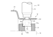
- the protruding portion 53 a is provided as a part of a die on the lower end surface of the supporting portion 53 of the nibler 50, and the guide member 130 is provided in place of the guide member 30. The movement from the cutting position to the lower mold 20 side and the movement of the nibler 50 downward from the cutting position may be restricted.
- the protruding portion 53 a is formed in a columnar shape having an outer diameter smaller than that of the die body 54, and protrudes downward from the lower end surface of the supporting portion 53.
- the guide member 130 is disposed below the flange portion of the workpiece W and closer to the lower mold 20 than the nibler 50 at the cutting position.
- the guide member 130 has a rectangular cross-sectional shape, and is continuously formed so as to surround the lower mold 20 along the movement path of the nibler 50.
- the side surface of the workpiece W on the side of the cut portion Wr contacts the side surface of the die body 54 of the nibler 50 in the cutting position, and the upper surface contacts the lower surface of the die body 54 of the nibler 50 in the cutting position. It is formed to do.
- the control device 60 controls the robot 40 so that the protruding portion 53a slides on the side surface of the guide member 130 and the die body 54 slides on the upper surface of the guide member 130.
- the workpiece W can be cut with high accuracy without the nibler 50 deviating from the movement path. That is, the side surface of the guide member 130 on the side of the cut portion Wr of the workpiece W functions as the first guide surface according to the present invention, and the upper surface of the guide member 130 functions as the second guide surface according to the present invention. .
- the guide member 30 is provided on the lower mold 20 side with respect to the nibler 50 at the cutting position, and the first guide surface 30a restricts the movement of the nibler 50 from the cutting position to the lower mold 20 side.
- the first guide surface 30a restricts the movement of the nibler 50 from the cutting position to the lower mold 20 side.
- a guide member 31 may be further provided in addition to the guide member 30. The guide member 31 is disposed below the flange portion of the workpiece W and closer to the cut portion Wr of the workpiece W than the nibler 50 at the cutting position.
- the guide member 31 is disposed below the cut portion Wr of the workpiece W.
- the guide member 31 has a rectangular cross-sectional shape and is continuously formed along the moving path of the nibler 50.
- a third guide surface 31 a that contacts the side surface of the die body 54 of the nibler 50 at the cutting position is formed on the side surface of the guide member 31 on the lower mold 20 side.
- the guide member 31 is provided so as to sandwich the die body 54 together with the guide member 30, the workpiece W can be cut with extremely high accuracy. That is, the first guide surface 30a of the guide member 30 functions as the first guide surface according to the present invention that restricts the nibler 50 from moving from the cutting position to the lower mold 20 side, and the third of the guide member 31.
- the guide surface 31a functions as a third guide surface according to the present invention that restricts the nibler 50 from moving from the cutting position toward the cut portion Wr of the workpiece W.
- the guide member 31 can be formed with a surface similar to the second guide surface 30 b of the guide member 30.
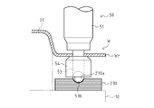
- the sphere 53b is provided as a part of the die at the lower end portion of the support portion 53 of the nibler 50, and the guide member 230 is provided in place of the guide member 30, whereby the nibler 50 is cut.
- the movement from the position to the lower mold 20 side, the movement of the nibbler 50 from the cutting position to the cut portion Wr side of the workpiece W, and the movement of the nibbler 50 downward from the cutting position may be regulated.
- the spherical body 53b is formed in a spherical shape having an outer diameter substantially the same as the outer diameter of the lower end surface of the support portion 53.
- the spherical body 53 b is fixed to the support portion 53 so that the lower portion protrudes downward from the lower end surface of the support portion 53.
- the guide member 230 is disposed below the flange portion of the workpiece W so as to support the nibler 50 at the cutting position.
- the guide member 230 has a substantially rectangular cross-sectional shape, and is continuously formed so as to surround the lower mold 20 along the movement path of the nibler 50.
- a groove 230 a having an arcuate cross-sectional shape into which the sphere 53 b is fitted is continuously formed along the moving path of the nibler 50.
- the guide member 230 is formed so that the surface of the groove 230a is in contact with the lower surface of the sphere 53b in the nibler 50 at the cutting position.
- the control device 60 controls the robot 40 so that the sphere 53b slides on the surface of the groove 230a in the guide member 230, so that the nibler 50 does not deviate from the moving path, and has extremely high accuracy. Can cut the workpiece W. That is, the surface of the groove part 230a of the guide member 230 functions as the first guide surface, the second guide surface, and the third guide surface according to the present invention.
- a guide member 330 can be provided instead of the guide member 30.
- the guide member 330 is disposed below the flange portion of the workpiece W and closer to the cut portion Wr of the workpiece W than the nibler 50 at the cutting position. That is, the guide member 330 is disposed below the cut portion Wr of the workpiece W.
- the guide member 330 is configured such that the upper surface thereof is in contact with the lower surface of the cut portion Wr of the workpiece W. That is, the guide member 330 is configured to support the cut portion Wr of the workpiece W from below.
- the guide member 330 is continuously formed so as to surround the lower mold 20 along the movement path of the nibler 50.
- the guide member 330 has a first guide surface 330a and a second guide surface 330b.
- the first guide surface 330a is formed in the vertical direction so as to come into contact with the side surface of the workpiece W on the side of the cut portion Wr in the die body 54 of the nibler 50 at the cutting position.
- the first guide surface 330a is formed continuously along the moving path of the nibler 50 so that the nibler 50 always contacts the side surface of the die body 54 when the nibler 50 cuts the workpiece W.
- the second guide surface 330b is formed in the horizontal direction so as to contact the lower surface of the die body 54 of the nibler 50 at the cutting position.
- the second guide surface 330b is continuous with the first guide surface 330a, and extends from the lower end of the first guide surface 330a toward the lower mold 20 side.
- the second guide surface 330b is formed so as to contact a part of the lower surface of the die main body 54 of the nibler 50 at the cutting position on the side of the cut portion Wr of the workpiece W.
- the second guide surface 330b is continuously formed along the moving path of the nibler 50 so that the nibler 50 always contacts the lower surface of the die body 54 when the nib 50 cuts the workpiece W.
- the guide member 330 configured in this way guides the nibler 50 so that the nibler 50 does not deviate from the movement path when the nibler 50 cuts the workpiece W. That is, the control device 60 controls the robot 40 so that the die body 54 slides on the first guide surface 330a and the second guide surface 330b of the guide member 330, so that the nibler 50 does not deviate from the movement path.
- the workpiece W can be cut with high accuracy.
- the guide member 330 is configured to support the cut portion Wr of the workpiece W, when the nibler 50 cuts the workpiece W, it is possible to reduce the vibration of the cut portion Wr of the workpiece W in the vertical direction. . Therefore, noise generated when the cut portion Wr of the workpiece W collides with the guide member 330 can be reduced.
- work W in the guide member 330 is used as the buffer part 330c.
- the buffer part 330c is comprised from the buffer material, and it can reduce the impact at the time of the cutting part Wr of the workpiece
- a guide member different from the guide member 330 may be provided on the lower mold 20 side with respect to the nibler 50 at the cutting position, and the die body 54 may be sandwiched between the guide member and the guide member 330. is there. As a result, the workpiece W can be cut with extremely high accuracy.
- the nibler 50 is moved so that a part of the die of the nibler 50 at the cutting position (the die main body 54, the protrusion 53a, or the sphere 53b) slides on the guide member.
- the number of the robots 40 is not limited, and at least one robot 40 to which the nibbler 50 is attached may be provided. Further, when two or more robots 40 are provided, the nibbler 50 may be attached to at least one robot 40.
- the present invention can be used for a cutting method and a cutting apparatus for cutting a steel plate.
Abstract
Description
一般的に、ニブラは、筒状のケースと、当該ケースの内部に設けられたパンチと、前記ケースの下方に設けられるダイスとを具備し、移動しつつ、前記ケースと前記ダイスとの間に供給される鋼板を、前記パンチによって連続的に打ち抜くことにより切断する。
特許文献1に記載のニブラは、当該ニブラに取り付けられた切断用治具の直線用ガイド板部を、矩形状の鋼板の側縁上で摺動させることによって、直線状に移動することが可能となっている。
更に、特許文献1に記載のニブラは、当該ニブラに取り付けられた切断用治具のセンター部を、鋼板に形成された孔に挿入することによって、当該孔を中心とする円状に移動することが可能となっている。
また、特許文献1に記載のニブラは、鋼板に形成された孔に挿入される、切断用治具のセンター部を利用して、鋼板を円状に切断することができるが、複雑な曲線状に切断することができない点で不利である。
切断装置1は、ワークWを切断するための装置である。
ワークWは、中央部が上方に向けて突出し、水平方向に延出するフランジ部が前記中央部の周囲に形成された鋼板である。
ガイド部材30の詳細な構成については後述する。
なお、説明の便宜上、図2(a)における上下方向をニブラ50の上下方向と定義する。
ケース51の内部には、パンチ52が上下方向に摺動可能に収納されている。
ケース51の内周面には、ケース51とダイス本体54とを支持するための支持部53が固定されている。
パンチ刃52aは、略蹄状の断面形状を有し、下端には、ワークWを打ち抜くための刃先が形成されている。パンチ刃52aは、パンチ52が下死点に達した際には、ケース51の下端から下方に突出し、後述のダイス穴54aに進入するように構成されている。
連結部52bは、駆動部55によってパンチ52が上下方向に往復運動するように、駆動部55に連結されている。
支持部53の下端部には、ダイス本体54が固定されている。
ダイス穴54aは、パンチ52が下死点に達した際に、パンチ刃52aが進入するように形成されている。詳細には、ダイス穴54aは、ダイス本体54と、支持部53におけるダイス本体54内に嵌挿されている部分との間に形成され、パンチ刃52aの断面形状に沿った形状で、ダイス本体54の上端面に開口している。
排出穴54bは、パンチ52によってワークWから打ち抜かれた三日月状のスクラップSをダイス本体54の外部へ排出するための穴である。排出穴54bは、ダイス本体54の側面に形成され、ダイス穴54aと連通している。
なお、ダイス本体54、および支持部53におけるダイス本体54内に嵌挿されている部分は、本発明に係る「ダイス」に相当する。
連結部55aは、パンチ52の連結部52bと連結されている。
ロッド55bは、モータ55cの動力を連結部55aに伝達するように、モータ55cと連結部55aとに接続されている。
モータ55cは、ロッド55bを介して、連結部55aに動力を伝達するように構成されている。モータ55cの回転運動は、ロッド55bを介して、連結部55aの上下運動に変換される。
図3に示すように、本実施形態においては、制御装置60は、ニブラ50がワークWのフランジ部の全周を巡って、ワークWのフランジ部における不要部分である切除部Wrを切除するように、ロボット40を制御する。
なお、図3は、ワークWの平面図であり、ワークW上の矢印は、ニブラ50の移動経路を示している。本実施形態においては、ワークWが平面視にて略矩形状に形成されている。
このように形成された第一案内面30aは、ニブラ50がワークWを切断する際、ダイス本体54が第一案内面30aよりも下型20側に移動することを規制する。
これにより、第一案内面30a上をダイス本体54が摺動するように、制御装置60がロボット40を制御することによって、ニブラ50がその移動経路から外れることを抑制できる。
したがって、ワークWの形状にかかわらず、精度良く所望の形状でワークWを切断することができる。
このように形成された第二案内面30bは、ニブラ50がワークWを切断する際、ダイス本体54が第二案内面30bよりも下方に移動することを規制する。
これにより、第二案内面30b上をダイス本体54が摺動するように、制御装置60がロボット40を制御することによって、ニブラ50のワークWに対する鉛直方向の位置を保持し、良好にワークWを切断することができる。
特に、ワークWのフランジ部が、鉛直方向の位置が変位するように湾曲した形状である場合でも、ニブラ50のワークWに対する鉛直方向の位置を保持し、良好にワークWを切断することができる。
これにより、ワークWから打ち抜かれたスクラップSが第二案内面30b上に排出されてニブラ50の移動を阻害することを防止できる。
なお、本実施形態においては、ガイド部材30に、第一案内面30aおよび第二案内面30bが形成されているが、少なくとも第一案内面30aが形成されていればよい。
また、第一案内面のみが形成されたガイド部材と、第二案内面のみが形成されたガイド部材とを設けることも可能である。
ただし、ガイド部材を、切断位置にあるニブラ50よりも下型20側に設けることにより、ワークWの切除部Wrの下方にガイド部材が位置しないこととなり、切除部WrがワークWから完全に切除された際に、ガイド部材上に留まることなく排出される。そのため、ガイド部材を切断位置にあるニブラ50よりも下型20側に設けることが好ましい。
例えば、図6に示すように、突出部53aをダイスの一部として、ニブラ50における支持部53の下端面に設けると共に、ガイド部材130を、ガイド部材30の代わりに設けることによって、ニブラ50が切断位置から下型20側に移動すること、およびニブラ50が切断位置から下方に移動することを規制してもよい。
突出部53aは、ダイス本体54よりも小さい外径を有する円柱状に形成され、支持部53の下端面から下方に突出している。
ガイド部材130は、ワークWのフランジ部の下方であって、切断位置にあるニブラ50よりも下型20側に配置されている。ガイド部材130は、矩形状の断面形状を有し、ニブラ50の移動経路に沿って、下型20を囲むように連続的に形成されている。ガイド部材130は、ワークWの切除部Wr側の側面が、切断位置にあるニブラ50のダイス本体54の側面に接触すると共に、上面が、切断位置にあるニブラ50のダイス本体54の下面に接触するように形成されている。
このような構成により、ガイド部材130の側面上を突出部53aが摺動するように、かつ、ガイド部材130の上面上をダイス本体54が摺動するように、制御装置60がロボット40を制御することによって、ニブラ50が移動経路から外れることなく、精度良くワークWを切断することができる。つまり、ガイド部材130における、ワークWの切除部Wr側の側面が、本発明に係る第一案内面として機能し、ガイド部材130の上面が、本発明に係る第二案内面として機能するのである。
例えば、図7に示すように、ガイド部材30に加えて、ガイド部材31を更に設ければよい。
ガイド部材31は、ワークWのフランジ部の下方であって、切断位置にあるニブラ50よりもワークWの切除部Wr側に配置されている。つまり、ガイド部材31は、ワークWの切除部Wrの下方に配置されている。ガイド部材31は、矩形状の断面形状を有し、ニブラ50の移動経路に沿って連続的に形成されている。ガイド部材31における、下型20側の側面には、切断位置にあるニブラ50のダイス本体54の側面に接触する第三案内面31aが形成されている。
このような構成により、ガイド部材30の第一案内面30a上、およびをガイド部材31の第三案内面31a上をダイス本体54が摺動するように、制御装置60がロボット40を制御することによって、ニブラ50が移動経路から外れることを抑制できる。
特に、ガイド部材31は、ガイド部材30と共にダイス本体54を挟むように設けられているため、極めて高い精度でワークWを切断することができる。つまり、ガイド部材30の第一案内面30aが、ニブラ50が切断位置から下型20側に移動することを規制する、本発明に係る第一案内面として機能すると共に、ガイド部材31の第三案内面31aが、ニブラ50が切断位置からワークWの切除部Wr側に移動することを規制する、本発明に係る第三案内面として機能するのである。
なお、ガイド部材31に、ガイド部材30の第二案内面30bと同様の面を形成することも可能である。
球体53bは、支持部53の下端面の外径と略同様の外径を有する球状に形成されている。球体53bは、その下部が支持部53の下端面から下方に突出するように、支持部53に固定されている。
ガイド部材230は、切断位置にあるニブラ50を支持するように、ワークWのフランジ部の下方に配置されている。ガイド部材230は、略矩形状の断面形状を有し、ニブラ50の移動経路に沿って、下型20を囲むように連続的に形成されている。ガイド部材230の上面には、球体53bが嵌合する円弧状の断面形状を有する溝部230aが、ニブラ50の移動経路に沿って連続的に形成されている。ガイド部材230は、溝部230aの表面が、切断位置にあるニブラ50における、球体53bの下部の表面に接触するように形成されている。
このような構成により、ガイド部材230における溝部230aの表面上を球体53bが摺動するように、制御装置60がロボット40を制御することによって、ニブラ50が移動経路から外れることなく、極めて高い精度でワークWを切断することができる。つまり、ガイド部材230の溝部230aの表面が、本発明に係る第一案内面、第二案内面および第三案内面として機能するのである。
なお、球体53bを回転自在に支持部53に取り付けることも可能である。
ガイド部材330は、ワークWのフランジ部の下方であって、切断位置にあるニブラ50よりもワークWの切除部Wr側に配置されている。つまり、ガイド部材330は、ワークWの切除部Wrの下方に配置されている。ガイド部材330は、その上面がワークWの切除部Wrの下面に接触するように構成されている。つまり、ガイド部材330は、ワークWの切除部Wrを下方から支持するように構成されている。ガイド部材330は、ニブラ50の移動経路に沿って、下型20を囲むように連続的に形成されている。ガイド部材330は、第一案内面330aと、第二案内面330bとを有する。
第一案内面330aは、切断位置にあるニブラ50のダイス本体54における、ワークWの切除部Wr側の側面に接触するように、鉛直方向に形成されている。第一案内面330aは、ニブラ50がワークWを切断する際に、常にダイス本体54の側面と接触するように、ニブラ50の移動経路に沿って連続的に形成されている。
第二案内面330bは、切断位置にあるニブラ50のダイス本体54の下面に接触するように、水平方向に形成されている。第二案内面330bは、第一案内面330aに連続し、第一案内面330aの下端から、下型20側に向けて延出している。第二案内面330bは、切断位置にあるニブラ50のダイス本体54の下面における、ワークWの切除部Wr側の一部分に接触するように形成されている。第二案内面330bは、ニブラ50がワークWを切断する際に、常にダイス本体54の下面と接触するように、ニブラ50の移動経路に沿って連続的に形成されている。
更に、ガイド部材330は、ワークWの切除部Wrを支持するように構成されているため、ニブラ50がワークWを切断する際、ワークWの切除部Wrが鉛直方向に振動することを低減できる。
したがって、ワークWの切除部Wrがガイド部材330に衝突する際に生じる騒音を低減できる。
緩衝部330cは、緩衝材から構成されており、ワークWの切除部Wrが緩衝部330cに衝突する際の衝撃を低減することが可能となっている。
したがって、ガイド部材330に緩衝部330cを設けることにより、ワークWの切除部Wrがガイド部材330に衝突する際に生じる騒音を更に低減できる。
なお、ガイド部材330とは別のガイド部材を、切断位置にあるニブラ50よりも下型20側に設け、当該ガイド部材とガイド部材330とによってダイス本体54を挟むように構成することも可能である。
これにより、極めて高い精度でワークWを切断することができる。
また、二つ以上のロボット40が設けられている場合、少なくとも一つのロボット40にニブラ50が取り付けられていればよい。
10 支持台
20 下型
30 ガイド部材
30a 第一案内面
30b 第二案内面
31 ガイド部材
31a 第三案内面
40 ロボット
50 ニブラ
54 ダイス本体
60 制御装置
W ワーク(鋼板)
Wr 切除部
Claims (11)
- 筒状のケースと、前記ケースの内部に収納され、上下方向に往復運動するパンチと、前記ケースの下方に設けられるダイスと、を有し、移動しつつ、前記ケースと前記ダイスとの間に供給される鋼板を、前記パンチによって連続的に打ち抜くように構成されたニブラを用いて、前記鋼板を切断する切断方法であって、
切断位置にある前記ニブラのダイスの側面が当接することにより、前記ニブラが当該切断位置から、前記ニブラの進行方向と上下方向とに直交する方向における一方に移動することを規制する第一案内面を有するガイド部材を、切断位置にある前記ニブラのダイス近傍に前記ニブラの移動経路に沿って設ける工程と、
前記ニブラを前記ガイド部材に沿って移動させる工程と、を含む、
ことを特徴とする切断方法。 - 前記ガイド部材は、切断位置にある前記ニブラのダイスの下面が当接することにより、前記ニブラが当該切断位置から下方に移動することを規制する第二案内面を更に有する、
ことを特徴とする請求項1に記載の切断方法。 - 前記ガイド部材は、前記ダイスに対して前記第一案内面とは反対側に配置されると共に、切断位置にある前記ニブラのダイスの側面が当接することにより、前記ニブラが当該切断位置から、前記ニブラの進行方向と上下方向とに直交する方向における他方に移動することを規制する第三案内面を更に有する、
ことを特徴とする請求項1または請求項2に記載の切断方法。 - 前記ガイド部材は、前記鋼板の不要部分である切除部の下面に接触し、当該切除部を下方から支持するように構成される、
ことを特徴とする請求項1乃至請求項3のいずれか一項に記載の切断方法。 - 前記ガイド部材は、前記鋼板の切除部と接触する部分が緩衝材から構成される、
ことを特徴とする請求項4に記載の切断方法。 - 前記ニブラを、位置および姿勢を変更可能なアームを有するロボットに取り付ける工程と、
前記ニブラが前記ガイド部材に沿って移動するように、前記ロボットを制御する工程と、を含む、
ことを特徴とする請求項1乃至請求項5のいずれか一項に記載の切断方法。 - 鋼板を切断するための切断装置であって、
位置および姿勢を変更可能なアームを有する、少なくとも一つのロボットと、
筒状のケースと、前記ケースの内部に収納され、上下方向に往復運動して前記鋼板を打ち抜くパンチと、前記ケースの下方に設けられるダイスと、を有し、前記ロボットのアームの先端に取り付けられるニブラと、
切断位置にある前記ニブラのダイス近傍に、前記ニブラの移動経路に沿って設けられるガイド部材と、
前記ニブラが前記ガイド部材に沿って移動するように、前記ロボットを制御する制御装置と、を具備し、
前記ガイド部材は、切断位置にある前記ニブラのダイスの側面が当接することにより、前記ニブラが当該切断位置から、前記ニブラの進行方向と上下方向とに直交する方向における一方に移動することを規制する第一案内面を有する、
ことを特徴とする切断装置。 - 前記ガイド部材は、切断位置にある前記ニブラのダイスの下面が当接することにより、前記ニブラが当該切断位置から下方に移動することを規制する第二案内面を更に有する、
ことを特徴とする請求項7に記載の切断装置。 - 前記ガイド部材は、前記ダイスに対して前記第一案内面とは反対側に配置されると共に、切断位置にある前記ニブラのダイスの側面が当接することにより、前記ニブラが当該切断位置から、前記ニブラの進行方向と上下方向とに直交する方向における他方に移動することを規制する第三案内面を更に有する、
ことを特徴とする請求項7または請求項8に記載の切断装置。 - 前記ガイド部材は、前記鋼板の不要部分である切除部の下面に接触し、当該切除部を下方から支持するように構成される、
ことを特徴とする請求項7乃至請求項9のいずれか一項に記載の切断装置。 - 前記ガイド部材は、前記鋼板の切除部と接触する部分が緩衝材から構成される、
ことを特徴とする請求項10に記載の切断装置。
Priority Applications (4)
| Application Number | Priority Date | Filing Date | Title |
|---|---|---|---|
| CN201280077880.1A CN104936732B (zh) | 2012-12-20 | 2012-12-20 | 切断方法以及切断装置 |
| JP2014552846A JP5924421B2 (ja) | 2012-12-20 | 2012-12-20 | 切断方法、および切断装置 |
| PCT/JP2012/083145 WO2014097461A1 (ja) | 2012-12-20 | 2012-12-20 | 切断方法、および切断装置 |
| US14/654,020 US20150314380A1 (en) | 2012-12-20 | 2012-12-20 | Cutting method and cutting apparatus |
Applications Claiming Priority (1)
| Application Number | Priority Date | Filing Date | Title |
|---|---|---|---|
| PCT/JP2012/083145 WO2014097461A1 (ja) | 2012-12-20 | 2012-12-20 | 切断方法、および切断装置 |
Publications (1)
| Publication Number | Publication Date |
|---|---|
| WO2014097461A1 true WO2014097461A1 (ja) | 2014-06-26 |
Family
ID=50977839
Family Applications (1)
| Application Number | Title | Priority Date | Filing Date |
|---|---|---|---|
| PCT/JP2012/083145 WO2014097461A1 (ja) | 2012-12-20 | 2012-12-20 | 切断方法、および切断装置 |
Country Status (4)
| Country | Link |
|---|---|
| US (1) | US20150314380A1 (ja) |
| JP (1) | JP5924421B2 (ja) |
| CN (1) | CN104936732B (ja) |
| WO (1) | WO2014097461A1 (ja) |
Families Citing this family (2)
| Publication number | Priority date | Publication date | Assignee | Title |
|---|---|---|---|---|
| CN109843465B (zh) * | 2016-09-26 | 2020-12-18 | 通快机床两合公司 | 用于板状工件的多冲程进展式切槽的方法、机床和切槽工具 |
| KR102066909B1 (ko) * | 2016-10-04 | 2020-01-16 | 주식회사 엘지화학 | 둥근 형태로 전극 리드를 가공할 수 있는 리드 가공 장치 및 이를 이용하여 가공된 전극 리드를 포함하는 가공된 전지셀 |
Citations (3)
| Publication number | Priority date | Publication date | Assignee | Title |
|---|---|---|---|---|
| US4012975A (en) * | 1975-07-31 | 1977-03-22 | Lalone Barry Grant | High speed punching apparatus and tool therefor |
| JPH11123623A (ja) * | 1997-10-22 | 1999-05-11 | Press Kogyo Co Ltd | 自動車用フレームの穴明け装置 |
| WO2012093494A1 (ja) * | 2011-01-07 | 2012-07-12 | トヨタ自動車株式会社 | ローラヘミング装置 |
Family Cites Families (35)
| Publication number | Priority date | Publication date | Assignee | Title |
|---|---|---|---|---|
| US2535631A (en) * | 1944-12-16 | 1950-12-26 | Charles B Gray | Sheet metal cutting tool |
| US2650663A (en) * | 1948-12-29 | 1953-09-01 | Wales | Apparatus for nibbling |
| US2844872A (en) * | 1956-05-07 | 1958-07-29 | Fenway Machine Company Inc | Sheet metal nibbling tool |
| US3835741A (en) * | 1971-06-16 | 1974-09-17 | Sentralinst For Ind Forskning | Device for cutting sheet material |
| US3780607A (en) * | 1972-01-03 | 1973-12-25 | Gerber Garment Technology Inc | Method and apparatus for cutting sheet material |
| US3785052A (en) * | 1972-06-27 | 1974-01-15 | Fenway Machine Co | Heavy duty nibbler |
| US3861037A (en) * | 1973-02-20 | 1975-01-21 | Lockheed Aircraft Corp | Nibbling tool |
| US3847049A (en) * | 1973-06-12 | 1974-11-12 | Trumpf Maschinen Ag Fa | Cutting tool having a reciprocating punch with a carrier member interconnecting a head portion and a die portion |
| US3988829A (en) * | 1975-01-30 | 1976-11-02 | Primex Equipment Company | Nibbler |
| DE2536525C3 (de) * | 1975-08-16 | 1979-10-04 | Trumpf Maschinen Ag, Zug (Schweiz) | Stanz- oder Nibbelmaschine |
| US4249309A (en) * | 1979-07-23 | 1981-02-10 | B. W. Darrah, Inc. | Rotating nibbler apparatus |
| US4545275A (en) * | 1983-02-07 | 1985-10-08 | Gerber Garment Technology, Inc. | Blade for severing fibrous material |
| DE3329902A1 (de) * | 1983-08-18 | 1985-02-28 | Siemens AG, 1000 Berlin und 8000 München | Periphere hilfseinrichtung zur automatischen beschickung- und entsorgung einer stanz-nibbel-maschine |
| US4674373A (en) * | 1984-10-16 | 1987-06-23 | Trumpf Gmbh & Co. | Method and apparatus for nibbling cutouts by rotation of tooling with cutting surfaces of different contours and tooling therefor |
| US4696211A (en) * | 1984-10-18 | 1987-09-29 | Trumpf Gmbh & Co. | Method and apparatus for nibbling cutouts with rectilinear and curvilinear contours by rotation of tooling with cutting surfaces of rectilinear and curvilinear contours and novel tooling therefor |
| CN1004995B (zh) * | 1985-05-09 | 1989-08-16 | 布赖恩·艾伦·贝内特 | 旋转步冲轮廓器 |
| JPH0450977Y2 (ja) * | 1987-07-14 | 1992-12-01 | ||
| US4916990A (en) * | 1987-12-23 | 1990-04-17 | Siemens Aktiengesellschaft | Method for controlling the path of a punching tool |
| DE3834722A1 (de) * | 1988-10-12 | 1990-04-19 | Fein C & E | Handgefuehrter knabber |
| JP2563955Y2 (ja) * | 1992-12-03 | 1998-03-04 | 日東工器株式会社 | 油圧パンチャ |
| US5575168A (en) * | 1994-01-12 | 1996-11-19 | Wilson Tool International, Inc. | Workpiece-deforming tool and die for use in a punch press |
| JPH09234622A (ja) * | 1996-02-29 | 1997-09-09 | Kiso Power Tool:Kk | ハンドニブラ |
| JP3452533B2 (ja) * | 2000-05-11 | 2003-09-29 | ファナック株式会社 | 目的形状部切離し装置、該装置を搭載したロボット及び切離し方法 |
| DE50100423D1 (de) * | 2001-12-06 | 2003-08-28 | Trumpf Werkzeugmaschinen Gmbh | Verfahren und Maschine zum mehrhubig fortschreitenden Schlitzen von plattenartigen Werkstücken, insbesondere von Blechen |
| DE102004005884B4 (de) * | 2004-02-05 | 2012-03-29 | Newfrey Llc | Fügeeinrichtung mit einem Stempelwerkzeug und einem Gegenwerkzeug und einem Halter |
| JP2008501534A (ja) * | 2004-06-08 | 2008-01-24 | タグ−ホイヤー エスアー | フェムトレーザーを用いたレーザー切断過程によるマイクロ機械部品またはナノ機械部品の製造方法 |
| JP4890868B2 (ja) * | 2006-01-18 | 2012-03-07 | リンテック株式会社 | シート切断装置及び切断方法 |
| EP2142321B1 (en) * | 2007-04-27 | 2016-12-14 | Wilson Tool International Inc. | Novel assemblies and methods for processing workpieces in ram-driven presses |
| TWI355313B (en) * | 2007-07-19 | 2012-01-01 | Toshiba Machine Co Ltd | Microscopic geometry cutting device and microscopi |
| CN101909843B (zh) * | 2007-12-27 | 2014-07-02 | 日本省力机械株式会社 | 毛刺去除系统、毛刺去除装置以及切削刀具 |
| CH702451A1 (de) * | 2009-12-17 | 2011-06-30 | Micromachining Ag | Verfahren zum Trennen einer Materialschicht mittels eines Schneidstrahls. |
| JP2012000631A (ja) * | 2010-06-16 | 2012-01-05 | Murata Machinery Ltd | パンチプレスの追切り切断用パンチ金型、コーナー切断用パンチ金型、および板材の開口形成方法 |
| EP2662160A4 (en) * | 2011-01-07 | 2017-01-25 | Murata Machinery, Ltd. | Punch die of a punch press, die for deepening cutting, and method of forming long holes in a plate |
| EP2533927B1 (de) * | 2011-04-28 | 2015-09-30 | Voith Patent GmbH | Stanz- und/oder nibbelmaschine sowie verfahren zum ansteuern einer stanz- und/oder nibbelmaschine |
| EP2929952B1 (en) * | 2012-11-30 | 2020-04-01 | Toyota Jidosha Kabushiki Kaisha | Steel sheet processing method and steel sheet processing device |
-
2012
- 2012-12-20 CN CN201280077880.1A patent/CN104936732B/zh active Active
- 2012-12-20 WO PCT/JP2012/083145 patent/WO2014097461A1/ja active Application Filing
- 2012-12-20 US US14/654,020 patent/US20150314380A1/en not_active Abandoned
- 2012-12-20 JP JP2014552846A patent/JP5924421B2/ja active Active
Patent Citations (3)
| Publication number | Priority date | Publication date | Assignee | Title |
|---|---|---|---|---|
| US4012975A (en) * | 1975-07-31 | 1977-03-22 | Lalone Barry Grant | High speed punching apparatus and tool therefor |
| JPH11123623A (ja) * | 1997-10-22 | 1999-05-11 | Press Kogyo Co Ltd | 自動車用フレームの穴明け装置 |
| WO2012093494A1 (ja) * | 2011-01-07 | 2012-07-12 | トヨタ自動車株式会社 | ローラヘミング装置 |
Also Published As
| Publication number | Publication date |
|---|---|
| CN104936732A (zh) | 2015-09-23 |
| JPWO2014097461A1 (ja) | 2017-01-12 |
| CN104936732B (zh) | 2016-11-23 |
| JP5924421B2 (ja) | 2016-05-25 |
| US20150314380A1 (en) | 2015-11-05 |
Similar Documents
| Publication | Publication Date | Title |
|---|---|---|
| US8443643B2 (en) | Burr removing method and device | |
| RU2596540C2 (ru) | Комбинированная машина для пробивки и лазерной резки плоского металлического листа | |
| JP5015777B2 (ja) | ばね弾性的に支承された工作物支持体を有する打抜き機 | |
| EP2623270A2 (en) | Parallel link robot system | |
| JP5924421B2 (ja) | 切断方法、および切断装置 | |
| JP6992055B2 (ja) | 板状工作物の加工のための工具および工具機械並びに方法 | |
| JP6421818B2 (ja) | 往復運動工具 | |
| JP2014014908A (ja) | ワーク支持装置 | |
| US20120291607A1 (en) | Groove processing apparatus | |
| JP5915767B2 (ja) | 切断装置、および切断方法 | |
| WO2014188539A1 (ja) | 切断装置、および切断方法 | |
| JP6619595B2 (ja) | プレス加工機 | |
| KR200480386Y1 (ko) | 가공물 가공장치 | |
| JP4532869B2 (ja) | ミクロジョイント切断装置 | |
| KR20140073149A (ko) | 유리판의 절단 장치 및 유리판의 절단 방법 | |
| JP2014231105A (ja) | 切断方法、および切断装置 | |
| JP5380505B2 (ja) | タレットパンチプレス | |
| JP6985550B1 (ja) | プレス装置 | |
| JP5962583B2 (ja) | ニブラ | |
| KR101874825B1 (ko) | 공작기계 | |
| KR20180000708U (ko) | 핸드 직소 전동공구용 톱날 지지 가이드장치 | |
| JP2017109922A (ja) | ガラス板の折割方法 | |
| CN109865868A (zh) | 多刀具台数控转塔冲床的改进 | |
| JP6134604B2 (ja) | 切削装置 | |
| JP5033336B2 (ja) | パンチ加工機 |
Legal Events
| Date | Code | Title | Description |
|---|---|---|---|
| 121 | Ep: the epo has been informed by wipo that ep was designated in this application |
Ref document number: 12890411 Country of ref document: EP Kind code of ref document: A1 |
|
| ENP | Entry into the national phase |
Ref document number: 2014552846 Country of ref document: JP Kind code of ref document: A |
|
| WWE | Wipo information: entry into national phase |
Ref document number: 14654020 Country of ref document: US |
|
| NENP | Non-entry into the national phase |
Ref country code: DE |
|
| 122 | Ep: pct application non-entry in european phase |
Ref document number: 12890411 Country of ref document: EP Kind code of ref document: A1 |