WO2014097414A1 - 置換変換装置及び置換変換方法 - Google Patents
置換変換装置及び置換変換方法 Download PDFInfo
- Publication number
- WO2014097414A1 WO2014097414A1 PCT/JP2012/082861 JP2012082861W WO2014097414A1 WO 2014097414 A1 WO2014097414 A1 WO 2014097414A1 JP 2012082861 W JP2012082861 W JP 2012082861W WO 2014097414 A1 WO2014097414 A1 WO 2014097414A1
- Authority
- WO
- WIPO (PCT)
- Prior art keywords
- conversion
- round
- replacement
- bit
- value
- Prior art date
- Legal status (The legal status is an assumption and is not a legal conclusion. Google has not performed a legal analysis and makes no representation as to the accuracy of the status listed.)
- Ceased
Links
Images



Classifications
-
- G—PHYSICS
- G09—EDUCATION; CRYPTOGRAPHY; DISPLAY; ADVERTISING; SEALS
- G09C—CIPHERING OR DECIPHERING APPARATUS FOR CRYPTOGRAPHIC OR OTHER PURPOSES INVOLVING THE NEED FOR SECRECY
- G09C1/00—Apparatus or methods whereby a given sequence of signs, e.g. an intelligible text, is transformed into an unintelligible sequence of signs by transposing the signs or groups of signs or by replacing them by others according to a predetermined system
-
- H—ELECTRICITY
- H04—ELECTRIC COMMUNICATION TECHNIQUE
- H04L—TRANSMISSION OF DIGITAL INFORMATION, e.g. TELEGRAPHIC COMMUNICATION
- H04L9/00—Cryptographic mechanisms or cryptographic arrangements for secret or secure communications; Network security protocols
- H04L9/06—Cryptographic mechanisms or cryptographic arrangements for secret or secure communications; Network security protocols the encryption apparatus using shift registers or memories for block-wise or stream coding, e.g. DES systems or RC4; Hash functions; Pseudorandom sequence generators
- H04L9/0618—Block ciphers, i.e. encrypting groups of characters of a plain text message using fixed encryption transformation
- H04L9/0631—Substitution permutation network [SPN], i.e. cipher composed of a number of stages or rounds each involving linear and nonlinear transformations, e.g. AES algorithms
-
- H—ELECTRICITY
- H04—ELECTRIC COMMUNICATION TECHNIQUE
- H04L—TRANSMISSION OF DIGITAL INFORMATION, e.g. TELEGRAPHIC COMMUNICATION
- H04L9/00—Cryptographic mechanisms or cryptographic arrangements for secret or secure communications; Network security protocols
- H04L9/06—Cryptographic mechanisms or cryptographic arrangements for secret or secure communications; Network security protocols the encryption apparatus using shift registers or memories for block-wise or stream coding, e.g. DES systems or RC4; Hash functions; Pseudorandom sequence generators
- H04L9/065—Encryption by serially and continuously modifying data stream elements, e.g. stream cipher systems, RC4, SEAL or A5/3
-
- H—ELECTRICITY
- H04—ELECTRIC COMMUNICATION TECHNIQUE
- H04L—TRANSMISSION OF DIGITAL INFORMATION, e.g. TELEGRAPHIC COMMUNICATION
- H04L9/00—Cryptographic mechanisms or cryptographic arrangements for secret or secure communications; Network security protocols
- H04L9/06—Cryptographic mechanisms or cryptographic arrangements for secret or secure communications; Network security protocols the encryption apparatus using shift registers or memories for block-wise or stream coding, e.g. DES systems or RC4; Hash functions; Pseudorandom sequence generators
- H04L9/0618—Block ciphers, i.e. encrypting groups of characters of a plain text message using fixed encryption transformation
- H04L9/0637—Modes of operation, e.g. cipher block chaining [CBC], electronic codebook [ECB] or Galois/counter mode [GCM]
Definitions
- the present invention relates to a technology of an apparatus and a method for replacing and converting a bit string.
- the replacement conversion is a conversion that takes a fixed-length bit string as an input and generates a bit string having the same length as the input.
- Non-Patent Document 1 includes an exclusive-OR of a bit string as an input and a round key bit string, a nonlinear layer that nonlinearly transforms the bit string every 4 bits, and a linear layer that diffuses the bit string by bit substitution.
- the block cipher PRESENT that can be implemented on a small scale by hardware is disclosed because replacement conversion is performed by repeating these and bit replacement can be processed only by connection. The block cipher has security against differential attacks.
- Non-Patent Document 1 has a problem that the block cipher PRESENT and its replacement conversion have a slow calculation speed when implemented by software.
- the present invention divides data by a specific index with respect to bit string data represented by using a plurality of indexes, performs nonlinear conversion for each divided data, Data is divided by another index, linear conversion is performed for each divided data, and a replacement value is generated by repeating these multiple times.
- X represented as X_ ⁇ i 0 i 1 ... i d-1 ⁇ using d i - bit indices i 0 , i 1 , ..., i d-1
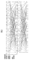
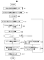
- Schematic which shows a substitution conversion apparatus Schematic which shows the round conversion part for 2 rounds. Schematic which shows a general computer. The flowchart figure which shows the process of a substitution conversion apparatus. The comparison figure of a prior art and this invention.
- the replacement conversion converts a 64-bit input value into a 64-bit output value.
- Each bit of the 64-bit variable W is counted as the 0th bit and the 1st bit in order from the left bit, the rightmost bit is called the 63rd bit, and each bit is W ⁇ 0 ⁇ , W ⁇ 1 ⁇ ,... W ⁇ 63 ⁇ .
- a continuous j-i + 1 bit from W ⁇ i ⁇ to W ⁇ j ⁇ is described as W ⁇ ij ⁇ .
- FIG. 1 is a schematic diagram of a substitution conversion apparatus 100 according to the first embodiment of the present invention.
- the replacement conversion apparatus 100 includes a storage unit 110, a control unit 120, an input unit 130, and an output unit 140.
- the storage unit 110 includes an initial value storage area 111, a constant round value storage area 112, a plaintext round value storage area 113, and a replacement value storage area 114.
- the initial value storage area 111 stores information for specifying an initial value when calculating a replacement.
- the initial value of the constant round value is stored as the initial value when calculating the replacement.
- the constant used for the initial value of the constant round value is not limited to these, and for example, a random number generated by a pseudo-random number generator or the like can be used.
- the constant round value storage area 112 stores information for specifying a constant round value for each round in each message block.
- the constant round value is generated by the round constant conversion unit 122 described later.
- the plaintext round value storage area 113 stores information for specifying a plaintext round value for each round.
- the plaintext round value is generated by the overall control unit 121, the initial conversion unit 122, and the round conversion unit 123, which will be described later.
- the replacement value storage area 114 stores replacement values calculated from plain text.
- the control unit 120 includes an overall control unit 121, a round constant conversion unit 122, an initial conversion unit 123, a round conversion unit 124, and a final conversion unit 125.
- the overall control unit 121 controls the entire processing in the replacement conversion apparatus 100.
- processing for managing the input equality and processing for managing the round constant generation unit 122, the initial conversion unit 123, the round conversion unit 124, and the final conversion unit 125 are performed.
- the input / output of the replacement conversion is 64 bits, but the present invention is not limited to this mode.
- the plaintext is X
- the round constant initial value is C (0) .
- the round constant conversion unit 122 calculates a constant round value and a round constant in each round.
- the round constant conversion unit 122 determines that the initial value C (0) of the constant round value stored in the initial value storage area 111 is not the first round in the case of the first round. the from the constant round value in the round stored in the constant round value storage area 112, by using the conversion function f c, calculates a constant round value in each round.
- the value c (r + 1) is calculated.
- ⁇ r is a function obtained by combining ⁇ r times.
- ⁇ 4 is an identity map.
- the function f C uses a linear feedback shift register (LFSR).
- the LFSR is determined by a polynomial.
- a polynomial g (x) for determining the LFSR is defined as the following equation (3).
- g (x) is a polynomial defined in the finite field GF (2).
- ⁇ X indicates a left shift of X bits
- >> Y indicates a right shift of Y bits
- ⁇ indicates an exclusive OR for each bit
- & Indicates a logical product for each bit.
- the initial conversion unit 123 is a process that converts plaintext only once before performing the first round conversion.
- the conversion by the initial conversion unit 123 is a linear conversion f initial that takes a 64-bit bit string X as an input and outputs a 64-bit bit string Y.
- the linear transformation f initial is described by the following equation (2).
- Y f initial (X)
- the round conversion unit 124 performs processing for calculating a plaintext round value in each round.
- the plaintext round value is calculated by the round conversion unit 124 using the round function f round shown in FIG. FIG. 2 shows two rounds of processing.
- the round function f round is a function that converts the plaintext round value X (r) of the r-th round into the plaintext round value X (r + 1) of the (r + 1) -th round.
- the round function f round includes a constant addition conversion layer AC, a non-linear conversion layer SL, and a linear conversion LL layer.
- the round conversion unit 124 uses the r-th round plaintext round value X (r) stored in the plaintext round value storage area 114 and the (r) round constant C (r ) stored in the round constant storage area. ) Is input to the constant addition conversion layer and converted to the value Y (r) .
- the constant addition conversion layer is expressed by the following equation (4).
- the round conversion unit 124 inputs the value Y (r) to the nonlinear conversion layer SL and converts it to the value Z (r) .
- the non-linear conversion layer SL is a conversion in which 16 4-bit S boxes are arranged in parallel, and is expressed by the following Expression 5.
- the 4-bit input / output replacement table S box S used in the non-linear conversion layer is defined by the following equation (6) and table.
- S [16] is an array in which values from S (0) to S (15) are arranged in order.
- the round conversion unit 124 inputs the value Z (r) to the linear conversion layer LL, and calculates a plaintext round value X (r + 1) of r + 1 rounds.
- the linear conversion layer LL is expressed by the following equation (7).
- the round conversion unit 124 replaces the calculated plaintext round value X (r + 1) of the r + 1 round with the plaintext round value of the r round and stores it in the plaintext round value storage area 113.
- the total number of rounds, which is the number of times the round conversion unit is repeated, is represented by R.
- the final conversion unit 125 takes the plaintext round value X (R) output in the final round as input, converts it by linear conversion, and converts it to a replacement value Y.
- the final conversion unit 125 uses f final as the linear conversion.
- f final is expressed by the following formula.
- the input unit 130 receives input of information.
- the output unit 140 outputs information.
- the replacement conversion apparatus 100 described above includes an external storage device such as a CPU (Central Processing Unit) 201, a memory 202, and an HDD (Hard Disk Drive) as shown in FIG. 3 (schematic diagram of the computer 200).
- a reading device 206 for reading / writing information from / to a portable storage medium 205 such as a CD-ROM (Compact Disk Read Only Memory) or DVD-ROM (Digital Versatile Disk Read Only Memory), a keyboard, a mouse, etc.
- a general computer 200 including an input device 207, an output device 208 such as a display, and a communication device 209 such as a NIC (Network Interface Card) for connecting to a communication network.
- NIC Network Interface Card
- the storage unit 110 can be realized by the CPU 201 using the memory 202 or the external storage device 204, and the control unit 120 loads a predetermined program stored in the external storage device 204 into the memory 202.
- the input unit 130 can be realized by using the input device 207 by the CPU 201, and the output unit 140 can be realized by using the output device 208 by the CPU 201. .
- This predetermined program is downloaded from the storage medium 205 via the reading device 206 or from the network via the communication device 209 to the external storage device 204, and then loaded onto the memory 202 and executed by the CPU 201. You may do it. Alternatively, the program may be directly loaded on the memory 202 from the storage medium 205 via the reading device 206 or from the network via the communication device 209 and executed by the CPU 201.
- the CPU 201 is a 32-bit CPU and includes a plurality of registers 203.
- the instruction set that can be executed by the CPU 201 includes exclusive OR instructions XOR A, B, AND instructions AND A, B, OR instructions OR A, B, and copy instructions COPY A, B. .
- the exclusive OR instructions XOR A and B are instructions that perform an exclusive OR for each bit of the values stored in the two registers A and B and overwrite the result on A.
- Logical product instructions AND A and B are instructions that perform bitwise logical product on the values stored in the two registers A and B and overwrite the result on A.
- OR instructions OR A and B are instructions that perform a bitwise OR operation on the values stored in the two registers A and B and overwrite the result with A.
- Copy instructions COPY A and B are instructions for copying the value of B to A.
- the instruction set that can be executed by the CPU 201 includes a bit inversion instruction NOT A.
- the bit inversion instruction NOT A is an instruction that performs bit inversion of each bit on the value stored in the register A and overwrites the result on A.
- the instruction set that can be executed by the CPU 201 includes a logical product instruction ANDi A, IMM with an immediate value.
- AND instruction ANDi A, IMM with immediate value is an instruction that performs logical AND for each bit of A and IMM on one register A and one 32-bit immediate value IMM and overwrites the result with A. .
- the instruction set that can be executed by the CPU 201 includes a right shift instruction SHR A, imm, a left shift instruction SHL A, imm, and a left 16-bit cyclic shift instruction ROL A, imm.
- the right shift instruction SHR A, imm is an instruction for shifting A to the right by imm bits with respect to one register A and one immediate value imm.
- Left shift instruction SHL A, imm is an instruction to shift A to the left by one mm for one register A and one immediate value imm.
- Left 16-bit cyclic shift instruction ROL A, imm is a command that cyclically shifts A by imm to the left by 16 bits for one register A and one immediate value imm.
- the instruction set that can be executed by the CPU 201 includes memory load instructions LOAD A and M.
- Memory load instructions LOAD A and M are instructions for copying 32-bit data stored in the memory address M to the register A.
- FIG. 4 is a flowchart showing the flow of processing in replacement conversion apparatus 100.
- the replacement conversion apparatus 100 receives an input of plaintext X through the input unit 130, and the overall conversion unit 121 of the replacement conversion apparatus 100 inputs the plaintext X to the initial conversion unit 123 (step S1).
- the initial conversion unit 123 converts the plaintext X, calculates the plaintext round value X (0) of the 0th round, and stores it in the plaintext round storage area 114 (step S2).
- the overall control unit 121 copies the round constant initial value C (0) stored in the initial value storage area 111 to the round constant storage area 113, and sets “0” to the value of the round counter r that is a counter of the number of rounds. "Is substituted (step S3).
- the overall control unit 121 inputs the plaintext round value X (r) stored in the plaintext round storage area 113 and C (r) stored in the round constant storage area 112 to the round conversion unit 124. (Step S4).
- the round conversion unit 124 calculates a plaintext round value X (r + 1) from the plaintext round value X (r) and the round constant value C (r) , and uses X (r + 1) as the plaintext round storage area 113. (Step S5).
- step S8 the overall control unit 121 inputs the round constant C (r-1) stored in the round constant storage area 112 to the round constant conversion unit 122 (step S8).
- the round constant conversion unit 122 calculates the round constant C (r) of the r-th round from the round constant C (r-1) of the r-1 round, and stores C (r) in the constant round storage area. Then, the overall control unit 121 returns to step S4 (step S9).
- step S10 the overall control unit 121 inputs the plaintext round value X (R) stored in the plaintext round storage area 113 to the final conversion unit 125 (step S10).
- the final conversion unit 125 calculates a replacement value Y from the plaintext round value X (R) and stores it in the replacement value storage area 114 (step S11).
- the overall control unit 121 outputs the replacement value Y stored in the replacement value storage area 114 via the output unit 140 (step S12).
- steps S1 to S12 in the figure can be realized by a general computer shown in FIG.
- step S1 64-bit plaintext X is held in the four registers REG0, REG1, REG2, and REG3 of the CPU as follows.
- REG0 X ⁇ 0-15 ⁇
- REG1 X ⁇ 16-31 ⁇
- REG2 X ⁇ 32-47 ⁇
- REG3 X ⁇ 48-63 ⁇ .
- the process of the initial conversion unit 123 in step S2 is not performed at all as a process on the computer.
- the initial conversion unit 123 is bit replacement performed to implement the bit slice implementation of the S box of the round conversion unit 124.
- step S3 the initial value C (0) of the round constant is loaded into the area storing the round constant of the memory, and 0 is loaded into the area holding the round counter r of the memory.
- step S4 the round constant C (r) is held in the registers REG4 to REG7 as follows.
- REG4 C (r) ⁇ 0-15 ⁇
- REG5 C (r) ⁇ 16-31 ⁇
- REG6 C (r) ⁇ 32-47 ⁇
- REG7 C (r) ⁇ 48-63 ⁇ .
- X (r) is already stored in REG0, REG1, REG2, REG3 when step 4 is entered, and is used as it is.
- step S5 constant addition layer conversion, S box layer conversion, and linear layer conversion are performed in the following order.
- MOV REG4, REG1 SHL REG1, 3 SHR REG4, 1 ANDi REG1, 0x8888 ANDi REG4, 0x7777 OR REG1, REG4 MOV REG5, REG2 SHL REG2, 2 SHR REG5, 2 ANDi REG2, 0xCCCC ANDi REG5, 0x3333 OR REG2, REG5 MOV REG6, REG3 SHL REG3, 1 SHR REG6, 3 ANDi REG3, 0xEEEE ANDi REG6, 0x1111 OR REG3, REG6 And As can be seen, when r divided by 4 is 0 or 2, it takes 3 instructions, and when 1 or 3, it takes 18 instructions. Therefore, on average, it takes (3 + 18 + 3 + 18) /4 10.5 instructions per round.
- step S7 the round constant C (r) stored in the constant round storage area is stored in the registers REG4 to REG7 as follows, and the round constant conversion unit 125 is called.
- REG4 C (r) ⁇ 0-15 ⁇
- REG5 C (r) ⁇ 16-31 ⁇
- REG5 C (r) ⁇ 32-47 ⁇
- REG6 C (r) ⁇ 48-64 ⁇ .
- step S8 according to the expression of the round constant conversion unit 125, an instruction corresponding to the pseudo code of the expression (3) is performed on C (r) stored in REG4 to REG7.
- step S9 the final conversion unit 124 is called.
- X (R) is already stored in REG0 to REG3 at the time of entering step S9, and since it is used as it is, it is not necessary to explicitly store X (R) again.
- step S11 the replacement output value Y stored in the registers R0 to R3 is output via the output unit.
- the number of instructions of replacement conversion 100 according to the present invention is estimated.
- the number of instructions is compared except for the constant conversion unit 122 of the present invention and the round key update unit of the prior art in order to compare the core parts of the replacement conversion.
- the key addition for one round can be calculated with two exclusive ORs, that is, two instructions, when the plaintext round value is stored in two 32-bit registers.
- the above is summarized as shown in FIG.
- FIG. 5 is a comparison diagram of the number of instructions of the prior art and the present invention.
- the reason why the non-linear conversion layer can be reduced from 32 instructions to 20 instructions is that the non-linear conversion layer is realized by combining logical operations between register values instead of referring to a table.
- the reason why the linear conversion layer can be reduced from 192 instructions to 10.5 instructions is that this processing is realized by register replacement and register value order or shift.
- the calculation amount can be reduced by defining the method of exchanging bit positions of linear transformation so that the above two points can be realized simultaneously.
- the replacement conversion 100 of the present embodiment has the same security as the conventional technique described in Document 1 against differential attacks. That is, the reference 1 shows that the difference characteristic probability of the substitution conversion of the prior art is 1/2 100 or less in 25 rounds, but the difference characteristic probability of the substitution conversion 100 of this embodiment is also 1/25 in 25 rounds. 2 Can be shown to be 100 or less.
- the round conversion unit 124 of this embodiment includes a constant addition layer, a non-linear conversion layer, and a linear conversion layer. When the upper bound of the difference characteristic probability is proved, attention is paid to the non-linear conversion layer and the linear conversion layer.
- the properties related to the proof of the upper bound of the differential characteristic probability are that the differential probability of the S box is 1/4 or less, and there is no propagation from the 1-bit difference to the 1-bit difference. That is two things.
- the 4-bit S box of this embodiment satisfies these two properties.
- the linear conversion layer is expressed by equation (7), but this can also be described as a combination of three conversions as follows.
- LL 0 is the same as the linear conversion layer of Document 1.
- ⁇ and ⁇ are transformations that shift the rightmost index. That is, ⁇ shifts the input order of bits to the S box, and ⁇ shifts the output order of bits from the S box.
- the permutation conversion of Document 1 and the permutation conversion 100 of the present embodiment have the same connection structure unless the bit order at the S box input / output is considered.
- the proof of the upper bound of the difference characteristic probability can be applied to the replacement conversion 100 of the present embodiment, which is equivalent to Document 1.
- differential characteristic probability of 25 rounds of substitution conversion 100 of the present embodiment is suppressed from above by 1/2 100. Therefore, in this sense, it can be said that it has security with respect to differential attacks.
- the linear conversion layer is defined by equation (7), but is not limited to this.
- equation (7) the following may be performed.
- the S box in the nonlinear conversion layer is represented by the expression (6), but other S boxes can be used.
- a 64-bit input / output substitution variable is configured, but the present invention is not limited to 64-bit.
- m d bit input / output permutation conversion can be configured for arbitrary natural numbers m and d.
- m is the input / output bit length of the S box to be used
- d is the number of indexes.
- the initial transformation f initial2 is
- the round transformation f round2 is a synthesis of the constant addition transformation layer AC 2 , the nonlinear transformation layer SL 2 , and the linear transformation layer LL 2 .
- f round2 is the round constant of round r is C (r).
- Nonlinear transformation layer SL 2 is
- the round conversion unit defined in this way can be implemented by software in a manner similar to the 64-bit input / output permutation conversion, and has high calculation speed in software implementation.
- LL 2 can also be more generally given by:
- substitution conversion is configured, but a block cipher can also be configured by giving a key instead of the initial value of the round constant.
- the round constant changing unit is not limited to the equation (1), and the bit length of the key is not limited to the same as the bit length of the replacement conversion.
- a block cipher using an 80-bit key can be used for 64-bit replacement conversion.
- the key update unit described in Document 1 can be used instead of the round constant conversion unit.
- substitution conversion device 110 storage unit 111 initial value storage area 112 round constant storage area 113 plaintext round value storage area 114 replacement value storage area 120 control unit 121 overall control unit 122 round constant conversion unit 123 initial conversion unit 124 round conversion unit 125 final Conversion unit 130 Input unit 140 Output unit 200 Computer 201 CPU 202 Memory 203 Register 204 External storage device 205 Storage medium 206 Reading device 207 Input device 208 Output device 209 Communication device
Landscapes
- Engineering & Computer Science (AREA)
- Computer Security & Cryptography (AREA)
- Computer Networks & Wireless Communication (AREA)
- Signal Processing (AREA)
- Physics & Mathematics (AREA)
- General Physics & Mathematics (AREA)
- Theoretical Computer Science (AREA)
- Compression, Expansion, Code Conversion, And Decoders (AREA)
Abstract
ハードウェアでの小規模実装とソフトウェアでの高速計算が可能で、かつ、安全性の高い置換変換装置を提供すること。 入力されたビット列のデータを初期変換部123で変換し、この変換されたデータをラウンド変換部124で繰り返し変換し、最後に最終変換部で変換したデータを、置換値として出力する。ビット列のデータは複数のインデックスを用いて表される。ラウンド変換部は、非線形変換と線形変換を含み、非線形変換は特定のインデックスにより分割されたデータ毎に変換を行い、線形変換は非線形変換とは異なるインデックスにより分割されたデータ毎に変換を行う。
Description
本発明は、ビット列を置換変換する装置及び方法の技術に関する。
置換変換は、ある固定長のビット列を入力として、入力と同じ長さのビット列を生成する変換である。
一般的に、ブロック暗号の鍵を固定した場合、その関数は置換変換となる。多くの場合、このようなブロック暗号は、入力された平文を繰り返しラウンド変換で変換することで、出力を計算する。ブロック暗号のうち、ハードウェア実装での必要なゲート数が少なくなるように設計された置換変換が存在する。特に、非特許文献1には、ビット列を入力にとり、ラウンド鍵のビット列への排他的論理和と、ビット列を4ビット毎に非線形変換を行う非線形層と、ビット列をビット置換により拡散する線形層とからなり、これらを繰り返すことで、置換変換を行い、ビット置換が結線だけで処理できるため、ハードウェアで小規模に実装できるブロック暗号PRESENTが開示されている。また、このブロック暗号は、差分攻撃に対して、安全性を有するものである。
A. Bogdanov , L. R. Knudsen , G. Le , C. Paar , A. Poschmann , M. J. B. Robshaw , Y. Seurin , C. Vikkelsoe, "PRESENT: An ultra-lightweight block cipher," CHES 2007, LNCS4727, pp.450-466, Springer 2007.
しかし、非特許文献1に記載の技術ではブロック暗号PRESENTやその置換変換は、ソフトウェアで実装した場合、計算速度が遅いという課題がある。
以上の課題を解決するため、本発明は、複数のインデックスを用いて表されたビット列のデータに対して、特定のインデックスによりデータを分割し、分割されたデータ毎に非線形変換を行い、さらに、他のインデックスによりデータを分割し、分割されたデータ毎に線形変換を行い、これらを複数回繰り返すことで、置換値を生成する。
例えば、2つの自然数mとdに対してmd個のビットからなり、n=md-1×i0+md-2×i1+...+m0×id-1番目のビットがd個のインデックスi0,i1,...,id-1を用いてX_{i0i1...id-1}と表される入力データXに対して、md-1個のmビットのビット列X_{i0i1...ik-10ik+1...id-1}X_{i0i1...ik-11ik+1...id-1}...X_{i0i1...ik-1(m-1)ik+1...id-1} (i0,i1,...,ik-1,ik+1,...,id-1=0,1,...,m-1)のそれぞれを非線形置換Sボックスで非線形変換により変換し、次にインデックスikが同じ値を持つビットの間でビットの入れ替えを行う線形変換により変換し、非線形変換での変換と線形変換での変換をあらかじめ決められた回数繰り返すことで、前記入力データXの置換値を生成する。
以上のように、本発明によれば、ハードウェアでの実装規模が小さく、差分攻撃に対する安全性を有し、かつ、ソフトウェア実装での計算高速性をもつ置換変換を提供することができる。
まず、本実施形態の説明に用いる記法について説明する。
本実施形態においては、置換変換は64ビットの入力値を64ビットの出力値に変換するようにしている。
本実施形態においては、置換変換は64ビットの入力値を64ビットの出力値に変換するようにしている。
64ビット変数Wの各ビットは、左のビットから順に0ビット目、1ビット目と数えられ、一番右のビットが63ビット目と呼ばれ、各ビットは順にW{0}, W{1}, … W{63}と記載される。さらに、別の表記としてWのnビット目のビットW{n}はn=16×i+4×j+kなる3つの0以上3以下の整数i,j,kを用いて、Wijk (=W{n})と記載される。また、W{i}からW{j}までの連続するj-i+1ビットをW{i-j}と記述する。また、kを固定しiとjを0から3まで走らせた16ビットの列をWkと記載する。つまり、
Wk= W00kW01kW02kW03kW10kW11kW12kW13kW20kW21kW22kW23kW30kW31kW32kW33k
である。さらに、iとjを固定し、kを0から3まで走らせた4ビットの列をWijと記載する。
Wk= W00kW01kW02kW03kW10kW11kW12kW13kW20kW21kW22kW23kW30kW31kW32kW33k
である。さらに、iとjを固定し、kを0から3まで走らせた4ビットの列をWijと記載する。
つまり、
Wij=Wij0Wij1Wij2Wij3,である。
Wij=Wij0Wij1Wij2Wij3,である。
図1は、本発明の第一の実施形態である置換変換装置100の概略図である。
図示するように、置換変換装置100は、記憶部110と、制御部120と、入力部130と、出力部140と、を備える。
記憶部110は、初期値記憶領域111と、定数ラウンド値記憶領域112と、平文ラウンド値記憶領域113と、置換値記憶領域114と、を備える。
記憶部110は、初期値記憶領域111と、定数ラウンド値記憶領域112と、平文ラウンド値記憶領域113と、置換値記憶領域114と、を備える。
初期値記憶領域111には、置換を計算する際の初期値を特定する情報が格納される。
本実施形態においては、置換を計算する際の初期値として、定数ラウンド値の初期値が記憶される。
ここで、定数ラウンド値の初期値は、例えば、c(0)=0xffffffffffffffffといった64ビットの定数が記憶される。
なお、定数ラウンド値の初期値に使用される定数はこれらに限定されるわけではなく、例えば、疑似乱数生成器等で生成された乱数を使用することも可能である。
定数ラウンド値記憶領域112には、各々のメッセージブロックにおけるラウンド毎の定数ラウンド値を特定する情報が格納される。
なお、本実施形態においては、定数ラウンド値は、後述するラウンド定数変換部122で生成される。
平文ラウンド値記憶領域113には、ラウンド毎の平文ラウンド値を特定する情報が格納される。
なお、本実施形態においては、平文ラウンド値は、後述する全体制御部121と、初期変換部122と、ラウンド変換部123と、で生成される。
置換値記憶領域114には、平文から計算される置換値が格納される。
制御部120は、全体制御部121と、ラウンド定数変換部122と、初期変換部123と、ラウンド変換部124と、最終変換部125と、を備える。
全体制御部121は、置換変換装置100における処理の全体を制御する。
特に、本実施形態においては、入力された平分を管理する処理や、ラウンド定数生成部122、初期変換部123、ラウンド変換部124、最終変換部125を管理する処理を行う。
ここで、本実施形態では、置換変換の入出力は64ビットとしているがこのような態様に限定されるわけではない。
なお、本実施形態においては、平文をXとし、ラウンド定数初期値をC(0)とする。
ラウンド定数変換部122は、各ラウンドにおける定数ラウンド値及びラウンド定数を算出する。
本実施形態においては、ラウンド定数変換部122は、最初のラウンドの場合には初期値記憶領域111に記憶されている定数ラウンド値の初期値C(0)から、または、最初のラウンドではない場合には定数ラウンド値記憶領域112に記憶されているラウンドにおける定数ラウンド値から、変換関数fcを用いて、各ラウンドにおける定数ラウンド値を算出する。
例えば、ラウンド定数変換部122は、前ラウンドrの定数ラウンド値c(r)(r=0の場合には定数ラウンド値の初期値C(0))を関数fcに入力して算出された値を、今ラウンドr+1の定数ラウンド値c(r+1)とする。
即ち、下記の(1)式に示されるようにして、前ラウンドの定数ラウンド値c(r)(r=0の場合には定数ラウンド値の初期値C(0))から今ラウンドの定数ラウンド値c(r+1)を算出する。

ここで、πrはπをr回合成した関数である。π4は恒等写像なることに注意。また、関数fCは、線形フィードバックシフトレジスタ(LFSR)を用いる。
一般に、LFSRは多項式で決定されるが、ここではLFSRを決定する多項式g(x)を、下記の(3)式のように定義する。
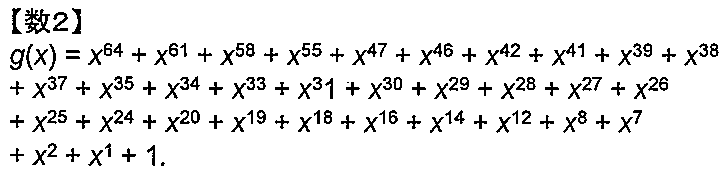
但し、g(x)は有限体GF(2)において定義される多項式である。
なお、関数fC(x)の擬似コードは、下記の(6)のように示される。
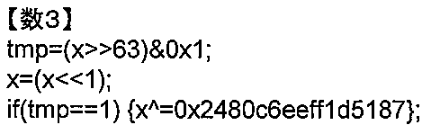
ここで、「<<X」は、Xビットの左シフトを示し、「>>Y」は、Yビットの右シフトを示し、「^」は、ビット毎の排他的論理和を示し、「&」は、ビット毎の論理積を示す。
初期変換部123は、始めのラウンド変換を行う前に一度だけ平文を変換する処理である。
例えば、初期変換部123による変換は、64ビットのビット列Xを入力としてとり、64ビットのビット列Yを出力する線形変換finitialである。線形変換finitialは次の式(2)で記述される。
Y=finitial(X)、
Yijk=Xkij (i,j,k=0,1,2,3)
図1に戻り、ラウンド変換部124は、各ラウンドにおける平文ラウンド値を算出する処理を行う。
Y=finitial(X)、
Yijk=Xkij (i,j,k=0,1,2,3)
図1に戻り、ラウンド変換部124は、各ラウンドにおける平文ラウンド値を算出する処理を行う。
例えば、ラウンド変換部124による平文ラウンド値の算出は、図2に示すラウンド関数froundを用いて行われる。図2には2ラウンド分の処理が描かれている。
ラウンド関数froundは、第rラウンドの平文ラウンド値X(r)を第r+1ラウンドの平文ラウンド値X(r+1)に変換する関数である。
ラウンド関数froundは、第rラウンドの平文ラウンド値X(r)を第r+1ラウンドの平文ラウンド値X(r+1)に変換する関数である。
具体的にはラウンド関数froundは定数加算変換層ACと、非線形変換層SLと、線形変換LL層と、からなる。まず、ラウンド変換部124は、平文ラウンド値記憶領域114に記憶されている第rラウンドの平文ラウンド値X(r)とラウンド定数記憶領域に記憶されている(r)ラウンドのラウンド定数C(r)を定数加算変換層に入力し、値Y(r)に変換する。定数加算変換層は、次の(4)式で表される。

次に、ラウンド変換部124は、値Y(r)を非線形変換層SLに入力し値Z(r)に変換する。非線形変換層SLは、16個の4ビットSボックスを並列に並べた変換であり、次の式5で表される。
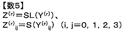
非線形変換層で用いる4ビット入出力の置換テーブルSボックスSは、以下の(6)式と表により定義される。

ここで、S[16]はS(0)からS(15)までの値を順に並べた配列である。
次に、ラウンド変換部124は、値Z(r)を線形変換層LLに入力しr+1ラウンドの平文ラウンド値X(r+1)を計算する。線形変換層LLは、次の(7)式で表される。
次に、ラウンド変換部124は、値Z(r)を線形変換層LLに入力しr+1ラウンドの平文ラウンド値X(r+1)を計算する。線形変換層LLは、次の(7)式で表される。

次に、ラウンド変換部124は、計算したr+1ラウンドの平文ラウンド値X(r+1)をrラウンドの平文ラウンド値に入れ替えて平文ラウンド値記憶領域113に記憶する。
また、ラウンド変換部を繰り返す回数である全ラウンド数はRで表す。
また、ラウンド変換部を繰り返す回数である全ラウンド数はRで表す。
本実施形態においては、R=31とする。
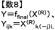
図1に戻り、最終変換部125は、最終ラウンドで出力された平文ラウンド値X(R)を入力としてとり、線形変換で変換し、置換値Yに変換する。
図1に戻り、最終変換部125は、最終ラウンドで出力された平文ラウンド値X(R)を入力としてとり、線形変換で変換し、置換値Yに変換する。
例えば、最終変換部125は、線形変換として、ffinalを用いる。
具体的には、ffinalは次の式で表される。
具体的には、ffinalは次の式で表される。
入力部130は、情報の入力を受け付ける。
出力部140は、情報を出力する。
出力部140は、情報を出力する。
以上に記載した置換変換装置100は、例えば、図3(計算機200の概略図)に示すような、CPU(Central Processing Unit)201と、メモリ202と、HDD(Hard Disk Drive)等の外部記憶装置204、CD-ROM(Compact Disk Read Only Memory)やDVD-ROM(Digital Versatile Disk Read Only Memory)等の可搬性を有する記憶媒体205に対して情報を読み書きする読書装置206と、キーボードやマウスなどの入力装置207と、ディスプレイなどの出力装置208と、通信ネットワークに接続するためのNIC(Network Interface Card)等の通信装置209と、を備えた一般的な計算機200で実現できる。
例えば、記憶部110は、CPU201がメモリ202又は外部記憶装置204を利用することにより実現可能であり、制御部120は、外部記憶装置204に記憶されている所定のプログラムをメモリ202にロードしてCPU201で実行することで実現可能であり、入力部130は、CPU201が入力装置207を利用することで実現可能であり、出力部140は、CPU201が出力装置208を利用することで実現可能である。
この所定のプログラムは、読書装置206を介して記憶媒体205から、あるいは、通信装置209を介してネットワークから、外部記憶装置204にダウンロードされ、それから、メモリ202上にロードされてCPU201により実行されるようにしてもよい。また、読書装置206を介して記憶媒体205から、あるいは、通信装置209を介してネットワークから、メモリ202上に直接ロードされ、CPU201により実行されるようにしてもよい。
CPU201は、32ビットCPUであり、複数のレジスタ203を備える。
CPU201が実行可能な命令セットには、排他的論理和命令XOR A,Bと、論理積命令AND A,Bと、論理和命令OR A,Bと、コピー命令COPY A,Bと、が含まれる。
排他的論理和命令XOR A,Bは、2つのレジスタA、Bに格納された値に対して、ビット毎の排他的論理和を行い、その結果をAに上書きする命令である。
排他的論理和命令XOR A,Bは、2つのレジスタA、Bに格納された値に対して、ビット毎の排他的論理和を行い、その結果をAに上書きする命令である。
論理積命令AND A,Bは、2つのレジスタA、Bに格納された値に対して、ビット毎の論理積を行い、その結果をAに上書きする命令である。
論理和命令OR A,Bは、2つのレジスタA、Bに格納された値に対して、ビット毎の論理和を行い、その結果をAに上書きする命令である。
コピー命令COPY A,Bは、Bの値をAにコピーする命令である。
さらに、CPU201が実行可能な命令セットには、ビット反転命令NOT A、が含まれる。
ビット反転命令NOT Aは、レジスタAに格納された値に対して、各ビットのビット反転を行い、その結果をAに上書きする命令である。
さらに、CPU201が実行可能な命令セットには、即値との論理積命令ANDi A,IMM、が含まれる。
即値との論理積命令ANDi A,IMMは、1つのレジスタAと1つの32ビットの即値IMMに対して、AとIMMのビット毎の論理積を行い、その結果をAに上書きする命令である。
さらに、CPU201が実行可能な命令セットには、右シフト命令SHR A,immと、左シフト命令SHL A,immと、左16ビット巡回シフト命令ROL A,immと、が含まれる。
右シフト命令SHR A,immは、1つのレジスタAと1つの即値immに対して、Aをimmビットだけ右にシフトする命令である。
左シフト命令SHL A,immは、1つのレジスタAと1つの即値immに対して、Aをimmだけ左にシフトする命令である。
左16ビット巡回シフト命令ROL A,immは、1つのレジスタAと1つの即値immに対して、Aをimmだけ左に16ビット単位で巡回シフトする命令である。
さらに、CPU201が実行可能な命令セットには、メモリロード命令LOAD A,Mが含まれる。
メモリロード命令LOAD A,Mは、メモリ番地Mに格納されている32ビットデータをレジスタAにコピーする命令である。
上述した命令のうち、XOR,AND,OR,COPY,NOT,ANDi,XORi,ROL,ROLC,SHR,SHL,ROL,LOAD命令はCPU201を用いて1サイクルで実行できるものとする。
図4は、置換変換装置100での処理の流れを表すフローチャートである。
まず、置換変換装置100では、入力部130を介して、平文Xの入力を受け付け、置換変換装置100は全体制御部121が、初期変換部123に平文Xを入力する(ステップS1)。
図4は、置換変換装置100での処理の流れを表すフローチャートである。
まず、置換変換装置100では、入力部130を介して、平文Xの入力を受け付け、置換変換装置100は全体制御部121が、初期変換部123に平文Xを入力する(ステップS1)。
そして、初期変換部123では、平文Xを変換して0ラウンド目の平文ラウンド値X(0)を計算し、平文ラウンド記憶領域114に記憶する(ステップS2)。
次に全体制御部121は、初期値記憶領域111に記憶されているラウンド定数初期値C(0)をラウンド定数記憶領域113にコピーし、ラウンド数のカウンタであるラウンドカウンタrの値に「0」を代入する(ステップS3)。
次に全体制御部121は、平文ラウンド記憶領域113に記憶されている平文ラウンド値X(r)とラウンド定数記憶領域112に記憶されているC(r)とを、ラウンド変換部124に入力する(ステップS4)。
次に、ラウンド変換部124では、平文ラウンド値X(r)とラウンド定数値C(r)から平文ラウンド値X(r+1)を計算し、X(r+1)を平文ラウンド記憶領域113に記憶する(ステップS5)。
次に、全体制御部121は、ラウンドカウンタrに1を加算してから(ステップS6)、r=Rとなっているか否か判断する(ステップS7)。
ステップS7でr=Rとなっていない場合には(ステップS7でNo)、ステップS8に進み、r=Rとなっている場合には(ステップS7でYes)、ステップS10に進む。
ステップS8では、全体制御部121は、ラウンド定数記憶領域112に記憶されているラウンド定数C(r-1)を、ラウンド定数変換部122に入力する(ステップS8)。
次に、ラウンド定数変換部122は、r-1ラウンド目のラウンド定数C(r-1)からrラウンド目のラウンド定数C(r)を計算し、C(r)を定数ラウンド記憶領域に記憶し、全体制御部121は、ステップS4に戻る(ステップS9)。
ステップS10では、全体制御部121は、平文ラウンド記憶領域113に記憶されている平文ラウンド値X(R)を最終変換部125に入力する(ステップS10)。
次に、最終変換部125は、平文ラウンド値X(R)から、置換値Yを計算し、置換値記憶領域114に記憶する(ステップS11)。
そして、全体制御部121は、置換値記憶領域114に記憶されている置換値Yを、出力部140を介して出力する(ステップS12)。
本実施形態においては、図のステップS1からS12は図3に示される一般的な計算機で実現できる。
まず、ステップS1においては、64ビットの平文XはCPUの4つのレジスタREG0,REG1,REG2,REG3に以下のように保持される。
REG0=X{0-15}、
REG1=X{16-31}、
REG2=X{32-47}、
REG3=X{48-63}.
次に、ステップS2の初期変換部123の処理は、計算機上での処理としては、一切行われない。初期変換部123は、ラウンド変換部124のSボックスのビットスライス実装を行うために行われるビット置換である。
REG0=X{0-15}、
REG1=X{16-31}、
REG2=X{32-47}、
REG3=X{48-63}.
次に、ステップS2の初期変換部123の処理は、計算機上での処理としては、一切行われない。初期変換部123は、ラウンド変換部124のSボックスのビットスライス実装を行うために行われるビット置換である。
次に、ステップS3においては、メモリのラウンド定数を格納する領域にラウンド定数の初期値C(0)をロードし、メモリのラウンドカウンタrを保持する領域に0をロードする。
次に、ステップS4では、ラウンド定数C(r)をREG4からREG7のレジスタに次のように保持する。
REG4=C(r){0-15}、
REG5=C(r){16-31}、
REG6=C(r){32-47}、
REG7=C(r){48-63}.
X(r)に関しては、ステップ4に入ったときにすでにREG0,REG1,REG2,REG3に格納されており、それをそのまま利用する。
REG4=C(r){0-15}、
REG5=C(r){16-31}、
REG6=C(r){32-47}、
REG7=C(r){48-63}.
X(r)に関しては、ステップ4に入ったときにすでにREG0,REG1,REG2,REG3に格納されており、それをそのまま利用する。
ステップS5では、定数加算層変換、Sボックス層変換、線形層変換が以下のように順に行われる。
まず、定数加算層変換では、X(r)とC(r)を保持したレジスタに対して以下が行われる。
XOR REG0、REG4
XOR REG1、REG5
XOR REG2、REG6
XOR REG3、REG7
これにより、REG0からREG3には式のY(r)がREG0=Y(r) 0、REG1=Y(r)1、REG2=Y(r) 2、REG3=Y(r) 3と格納される。命令数は4命令である。
XOR REG0、REG4
XOR REG1、REG5
XOR REG2、REG6
XOR REG3、REG7
これにより、REG0からREG3には式のY(r)がREG0=Y(r) 0、REG1=Y(r)1、REG2=Y(r) 2、REG3=Y(r) 3と格納される。命令数は4命令である。
次に、Sボックス層変換では、Y(r)を格納するREG0からREG3に対して以下の命令が行われれ、Z(r)が計算される。
MOV REG4, REG0
AND REG0,REG2
XOR REG0,REG3
XOR REG2,REG1
XOR REG2,REG0
OR REG3,REG4
XOR REG3,REG1
XOR REG4,REG2
MOV REG1,REG3
OR REG3,REG4
XOR REG3,REG0
AND REG0,REG1
XOR REG4,REG0
XOR REG1,REG3
XOR REG1,REG4
NOT REG4
MOV REG0、REG2
MOV REG2,REG1
MOV REG1、REG3
MOV REG3、REG4
これにより、REG0からREG3には式のZ(r)がREG0=Z(r) 0、REG1=Z(r) 1、REG2=Z(r) 2、REG3=Z(r) 3と格納される。命令数は、16命令である。
MOV REG4, REG0
AND REG0,REG2
XOR REG0,REG3
XOR REG2,REG1
XOR REG2,REG0
OR REG3,REG4
XOR REG3,REG1
XOR REG4,REG2
MOV REG1,REG3
OR REG3,REG4
XOR REG3,REG0
AND REG0,REG1
XOR REG4,REG0
XOR REG1,REG3
XOR REG1,REG4
NOT REG4
MOV REG0、REG2
MOV REG2,REG1
MOV REG1、REG3
MOV REG3、REG4
これにより、REG0からREG3には式のZ(r)がREG0=Z(r) 0、REG1=Z(r) 1、REG2=Z(r) 2、REG3=Z(r) 3と格納される。命令数は、16命令である。
そして、線形層変換ではrの値によって、REG1からREG3に対して以下の命令が行われ、Z(r)からX(r+1)が計算される。
rを4で割った余りが0の場合は、
ROTL REG1、4
ROTL REG2、8
ROTL REG3、12
とする。
ROTL REG1、4
ROTL REG2、8
ROTL REG3、12
とする。
rを4で割った余りが1の場合は、
MOV REG4、REG1
SHL REG1、1
SHR REG4、3
ANDi REG1、0xEEEE
ANDi REG4、0x1111
OR REG1、REG4
MOV REG5、REG2
SHL REG2、2
SHR REG5、2
ANDi REG2、0xCCCC
ANDi REG5、0x3333
OR REG2、REG5
MOV REG6、REG3
SHL REG3、3
SHR REG6、1
ANDi REG3、0x8888
ANDi REG6、0x7777
OR REG3、REG6
とする。
MOV REG4、REG1
SHL REG1、1
SHR REG4、3
ANDi REG1、0xEEEE
ANDi REG4、0x1111
OR REG1、REG4
MOV REG5、REG2
SHL REG2、2
SHR REG5、2
ANDi REG2、0xCCCC
ANDi REG5、0x3333
OR REG2、REG5
MOV REG6、REG3
SHL REG3、3
SHR REG6、1
ANDi REG3、0x8888
ANDi REG6、0x7777
OR REG3、REG6
とする。
rを4で割った余りが2の場合は、
ROTL REG1、12
ROTL REG2、8
ROTL REG3、4
とする。
ROTL REG1、12
ROTL REG2、8
ROTL REG3、4
とする。
rを4で割った余りが3の場合は、
MOV REG4、REG1
SHL REG1、3
SHR REG4、1
ANDi REG1、0x8888
ANDi REG4、0x7777
OR REG1、REG4
MOV REG5、REG2
SHL REG2、2
SHR REG5、2
ANDi REG2、0xCCCC
ANDi REG5、0x3333
OR REG2、REG5
MOV REG6、REG3
SHL REG3、1
SHR REG6、3
ANDi REG3、0xEEEE
ANDi REG6、0x1111
OR REG3、REG6
とする。これから分かるとおり、rを4で割ったあまりが0か2の場合は、3命令かかっており、1か3の場合は、18命令かかっている。従って、平均すると1ラウンドあたり、(3+18+3+18)/4=10.5命令かかる。
MOV REG4、REG1
SHL REG1、3
SHR REG4、1
ANDi REG1、0x8888
ANDi REG4、0x7777
OR REG1、REG4
MOV REG5、REG2
SHL REG2、2
SHR REG5、2
ANDi REG2、0xCCCC
ANDi REG5、0x3333
OR REG2、REG5
MOV REG6、REG3
SHL REG3、1
SHR REG6、3
ANDi REG3、0xEEEE
ANDi REG6、0x1111
OR REG3、REG6
とする。これから分かるとおり、rを4で割ったあまりが0か2の場合は、3命令かかっており、1か3の場合は、18命令かかっている。従って、平均すると1ラウンドあたり、(3+18+3+18)/4=10.5命令かかる。
次に、ステップS6においては、ラウンドカウンタrに1を加算し、ラウンドカウンタrを保持する領域に保存し、r=Rか否かを判断する。
ステップS7では、定数ラウンド格納領域に格納されたラウンド定数C(r)をレジスタREG4からREG7に以下のように格納し、ラウンド定数変換部125を呼び出す。
REG4=C(r){0-15}、
REG5=C(r){16-31}、
REG5=C(r){32-47}、
REG6=C(r){48-64}.
ステップS8では、ラウンド定数変換部125の式に従い、REG4からREG7に格納されたC(r)に対して、(3)式の擬似コードに対応した命令が行われる。
REG4=C(r){0-15}、
REG5=C(r){16-31}、
REG5=C(r){32-47}、
REG6=C(r){48-64}.
ステップS8では、ラウンド定数変換部125の式に従い、REG4からREG7に格納されたC(r)に対して、(3)式の擬似コードに対応した命令が行われる。
ステップS9では、最終変換部124が呼び出される。ただし、ステップS9に入った時点ですでに、X(R)はREG0からREG3に格納されており、それをそのまま用いるため、X(R)を明示的に格納しなおす必要はない。
ステップS10の最終変換部では、コンピュータによる処理を行う必要はない。これは、最終変換部の式により、REG0=Y{0-15}、REG1=Y{16-31}、REG2=Y{32-47}、REG3=Y{48-63}、が成り立つためである。
ステップS11では、レジスタR0からR3に格納されている置換出力値Yを、出力部を介して出力する。
ステップS11では、レジスタR0からR3に格納されている置換出力値Yを、出力部を介して出力する。
非特許文献1に記載の従来技術と比較するため、本発明による置換変換100の命令数を見積もる。比較においては、置換変換の核となる部分の比較とするため、本発明の定数変換部122と従来技術のラウンド鍵更新部は除いて、命令数を比較する。
本発明においては、前記のとおり、ラウンド定数変換部122を除いた1ラウンドあたりの命令数は、4+20+10.5=34.5命令である。全31ラウンドの場合、1062命令かかる。
文献1に記載の従来技術では、1ラウンド分の鍵加算は、32ビットレジスタ2つに平文ラウンド値を格納する実装をする場合は、2回の排他的論理和、つまり2命令で計算できる。1ラウンド分の非線形変換層は、16個の4ビット値xi (i=0,…,15)に対して、yi=S(xi)をメモリ参照により行う。一つのiに対して、xiのレジスタへの移動とxiのオフセットによるSbox表のメモリ参照の2命令が必要となるため、1ラウンド分の非線形変換層は2×16=32回のRISC命令がかかると見積もれる。また、従来技術の線形変換層は、Yijk=Xjkiと記述されるが、これを1ビットずつの移動で計算する場合、1ビットあたり、ビットの読み出しで1回のAND命令、ビットの移動で1回のシフト命令、移動結果同士の結合で1回のOR命令がかかる。つまり、1ラウンド分の線形変換層は、3×64=192命令かかると見積もることができる。従って、ラウンド鍵更新部を除いた1ラウンドあたりの計算量は、2+32+192=226命令と見積もられる。全31ラウンドの場合、7006命令かかる。
従って、上記見積もりによると、本発明では文献1に記載の従来技術に比べて7006/1062=約6.6倍の高速化を達成できる。以上をまとめると図5の通りである。
図5は、従来技術と本発明の命令数の比較図である。
図5に記載の通り、非線形変換層を、32命令から20命令に減らせたのは、テーブル参照ではなく、レジスタ値同士の論理演算を組み合わせて非線形変換層を実現することによる。線形変換層を、192命令から10.5命令に減らせたのが、レジスタの入れ替えとレジスタ値の順かシフトでこの処理を実現することによる。上記2点を同時に実現可能となるように、線形変換のビット位置入れ替え方を定めたことにより演算量を削減できた。
図5に記載の通り、非線形変換層を、32命令から20命令に減らせたのは、テーブル参照ではなく、レジスタ値同士の論理演算を組み合わせて非線形変換層を実現することによる。線形変換層を、192命令から10.5命令に減らせたのが、レジスタの入れ替えとレジスタ値の順かシフトでこの処理を実現することによる。上記2点を同時に実現可能となるように、線形変換のビット位置入れ替え方を定めたことにより演算量を削減できた。
また、本実施形態の置換変換100は差分攻撃に対して文献1記載の従来技術と同等の安全性を有する。つまり、文献1において従来技術の置換変換の差分特性確率は25ラウンドで1/2100以下であることが示されているが、本実施例の置換変換100の差分特性確率も25ラウンドで1/2100以下であることが示せる。本実施形態のラウンド変換部124は、定数加算層と非線形変換層、線形変換層からなるが、差分特性確率の上界を証明する際には非線形変換層と線形変換層に着目する。また、4ビットSボックスに関しても、差分特性確率の上界の証明に関わる性質は、Sボックスの差分確率は1/4以下であることと、1ビット差分から1ビット差分への伝播は存在しないこと、の2つである。本実施形態の4ビットSボックスは、この2つの性質を満たしている。また、線形変換層は、(7)式で表されているが、これは次のように3つの変換の合成としても記述できる。

ここで、LL0は文献1の線形変換層と同一のものである。また、ρとσは一番右のインデックスをずらす変換である。つまり、σはSボックスへのビットの入力順、ρはSボックスからのビットの出力順をずらすものである。従って、文献1の置換変換と本実施例の置換変換100とでは、Sボックス入出力でのビット順を考えなければ、結線構造は同じものとなる。このことから、差分特性確率の上界の証明は文献1と同等のものが本実施例の置換変換100にも適用できることになる。つまり、本実施例の置換変換100の25ラウンドの差分特性確率は1/2100で上から抑えられる。従って、この意味において差分攻撃に関して安全性を有するといえる。
本実施形態では、線形変換層は(7)式で定義したが、これに限られるものではない。例えば、(7)式の代わりに、次のようにすることもできる。
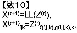
ここで、f(i,j,k), g(i,j,k)は値域が{0,1,2,3}の関数である。ただし、kを固定し、i,jそれぞれを{0,1,2,3}の全ての値を走らせた時、(f(i,j,k),g(i,j,k))は、(a,b) a=0,1,2,3, b=0,1,2,3 の16通りの各値を1回ずつとるものとする。
また、本実施形態では、非線形変換層でのSボックスを(6)式としたが、これ以外のSボックスを用いることもできる。
本実施形態では、64ビット入出力の置換変数を構成したが、本発明は64ビットに限定されるものではない。本発明によれば、例えば、任意の自然数mとdに対して、mdビット入出力の置換変換を構成できる。ここで、mは用いるSボックスの入出力ビット長、dはインデックスの個数である。mdビットの平文Wのnビット目をW{n}とする。一番左のビットは0ビット目と数え、一番右のビットはmd-1ビット目と数える。また、n=i0×md-1+i1×md-2+…+id-1×m0を満たす、d個の0以上m-1以下の整数を用いて、W{n}=W_{i0i1…id-1}とも表す。ここでは、二段のインデックスとなるため、表記上の問題から1段目のインデックスはW_{インデックス}で表されている。この場合も、置換変換は前記実施形態と同様に、初期変換、R回のラウンド変換、最終変換をこの順番で計算するもので構成される。ただし、ここでの各変換は、例えば以下のようなものがある。以下ではmdビットの平文をX、mdビットの置換値をYとする。
初期変換finitial2は、

で表される。
ラウンド変換fround2は、定数加算変換層AC2と非線形変換層SL2、線形変換層LL2の合成である。
ラウンド変換fround2は、定数加算変換層AC2と非線形変換層SL2、線形変換層LL2の合成である。
fround2は、rラウンド目のラウンド定数をC(r)とすると、

と定義される。
定数加算層AC2は、

と定義される。
非線形変換層SL2は、
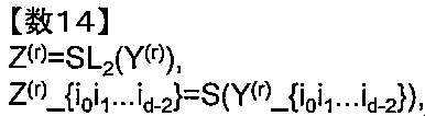
と定義される。ただし、Y(r)_{i0i1...id-2}は、

で定義されるmビット列である。Z(r)_{i0i1...id-2}も同様に定義される。
線形変換層LL2は、

と定義される。
このように定義されたラウンド変換部は、前記64ビット入出力の置換変換と類似の方法によりソフトウェアで実装でき、ソフトウェア実装での計算高速性を有する。
また、LL2はより一般的に次の式とすることもできる。
また、LL2はより一般的に次の式とすることもできる。
F0(i0,i1,...,id-1), f1(i0,i1,...,id-1),fd-2(i0,i1,...,id-1)は、id-1を固定してi0,i1,...,id-2をそれぞれ0からm-1まで走らせたとき、(f0(i0,...,id-1),...,fd-2(i0,...,id-1))は、(a0,...,ad-2) (a0,...,ad-2=0,1,...,m-1)の計md-1通りの組み合わせを各1回ずつとるものとする。
本実施形態では、置換変換を構成しているが、前記ラウンド定数の初期値の代わりに鍵を与えることで、ブロック暗号を構成することもできる。この際、前記ラウンド定数変更部は(1)式に限られるものではなく、鍵のビット長は置換変換のビット長と同一のものに限られるものではない。例えば、文献1の従来技術のように、64ビットの置換変換に対して、80ビットの鍵を用いるブロック暗号とすることもできる。この場合、例えば前記ラウンド定数変換部の代わりに、文献1に記載の鍵更新部を用いることもできる。
100 置換変換装置
110 記憶部
111 初期値記憶領域
112 ラウンド定数記憶領域
113 平文ラウンド値記憶領域
114 置換値記憶領域
120 制御部
121 全体制御部
122 ラウンド定数変換部
123 初期変換部
124 ラウンド変換部
125 最終変換部
130 入力部
140 出力部
200 計算機
201 CPU
202 メモリ
203 レジスタ
204 外部記憶装置
205 記憶媒体
206 読書装置
207 入力装置
208 出力装置
209 通信装置
110 記憶部
111 初期値記憶領域
112 ラウンド定数記憶領域
113 平文ラウンド値記憶領域
114 置換値記憶領域
120 制御部
121 全体制御部
122 ラウンド定数変換部
123 初期変換部
124 ラウンド変換部
125 最終変換部
130 入力部
140 出力部
200 計算機
201 CPU
202 メモリ
203 レジスタ
204 外部記憶装置
205 記憶媒体
206 読書装置
207 入力装置
208 出力装置
209 通信装置
Claims (10)
- 入力データXを受信する入力部と、
複数のビット列Xのそれぞれを非線形置換Sボックスを記憶する記憶部と、
前記入力データXを前記非線形置換Sボックスで非線形変換により変換し、インデックスikが同じ値を持つビットの間でビットの入れ替えを行う線形変換により変換し、
前記非線形変換での変換と前記線形変換での変換をあらかじめ決められた回数繰り返すことで、前記入力データXの置換値を生成するラウンド変換部とを備える
ことを特徴とする置換変換装置。 - 請求項1に記載の置換変換装置であって、
前記入力データXとは2つの自然数mとdに対してmd個のビットからなり、n=md-1×i0+md-2×i1+...+m0×id-1番目のビットがd個のインデックスi0,i1,...,id-1を用いてX_{i0i1...id-1}と表され、
前記ビット列とは、md-1個のmビットのビット列X_{i0i1...ik-10ik+1...id-1}X_{i0i1...ik-11ik+1...id-1}...X_{i0i1...ik-1(m-1)ik+1...id-1} (i0,i1,...,ik-1,ik+1,...,id-1=0,1,...,m-1)であることを特徴とする置換変換装置。 - 請求項2に記載の置換変換装置であって、
前記ラウンド変換部は、前記非線形変換での変換の前に、前記入力データXをあらかじめ決められた定数回、排他的論理和することで変換し、
定数の排他的論理和による変換と、前記線形変換による変換と、前記線形変換による変換と、を繰り返しの単位とし、
排他的論理和される定数は繰り返し毎に異なるあらかじめ決められた定数である、
ことを特徴とする置換変換装置。 - 請求項3に記載の置換変換装置であって、
前記ラウンド変換部は、前記線形変換は前記入力データXをY_{i0i1...id-2id-1}=X_{i1i2...(id-1-i0)id-1}に従い変換し、出力を出力データYとするものであること、
を特徴とする置換変換装置。 - 請求項3に記載の置換変換装置であって、
前記ラウンド変換部は、前記自然数mは4、dは3であって、前記線形変換は前記入力データXをY_{i0i1i2}=X_{i1(i2-i0)i2}に従い変換し、出力を出力データYとするものであること、
を特徴とする置換変換装置。 - 請求項5に記載の置換変換装置であって、
前記非線形変換Sボックスは、置換表Sbox[16]={ 8, 6, 7, 9, 3, 12, 10, 15, 13, 1, 14, 4, 0, 11, 5, 2}であること、
を特徴とする置換変換装置。 - 請求項6に記載の置換変換装置であって、
処理を始める前に前記データXをYにY_{i0i1i2}=X_{i2i0i1}と変換してから、Yに対して前記定数加算変換と、前記非線形変換と、前記線形変換と、を繰り返し行い中間値Zを計算し、中間値ZをW_{i0i1i2}=Z_{i2(-i1)i0}に従い変換し、値Wを置換値として出力すること、
を特徴とする置換変換装置。 - 請求項7に記載の置換変換装置であって、
前記値Xを、REGi=X00iX01iX02iX03iX10iX11iX12iX13iX20iX21iX22iX23iX30iX31iX32iX33i i=0,1,2,3と4つに分割しておき、前記非線形変換をREGi間のビット毎論理演算で計算し、前記線形変換をREGi毎のビットシフトとビット巡回シフトとビット毎論理演算で計算すること、
を特徴とする置換変換装置。 - 置換変換装置が、
2つの自然数mとdに対してmd個のビットからなり、n=md-1×i0+md-2×i1+...+m0×id-1番目のビットがd個のインデックスi0,i1,...,id-1を用いてX_{i0i1...id-1}と表される入力データXに対して、md-1個のmビットのビット列X_{i0i1...ik-10ik+1...id-1}X_{i0i1...ik-11ik+1...id-1}...X_{i0i1...ik-1(m-1)ik+1...id-1} (i0,i1,...,ik-1,ik+1,...,id-1=0,1,...,m-1)のそれぞれを非線形置換Sボックスで非線形変換により変換し、次にインデックスikが同じ値を持つビットの間でビットの入れ替えを行う線形変換により変換し、
前記非線形変換での変換と前記線形変換での変換をあらかじめ決められた回数繰り返すことで、前記入力データXの置換値を生成する置換生成方法。 - 請求項2に記載の置換変換装置であって、
排他的論理和される前記定数の代わりに鍵データを排他的論理輪する、
ことを特徴とする置換変換装置。
Priority Applications (1)
| Application Number | Priority Date | Filing Date | Title |
|---|---|---|---|
| PCT/JP2012/082861 WO2014097414A1 (ja) | 2012-12-19 | 2012-12-19 | 置換変換装置及び置換変換方法 |
Applications Claiming Priority (1)
| Application Number | Priority Date | Filing Date | Title |
|---|---|---|---|
| PCT/JP2012/082861 WO2014097414A1 (ja) | 2012-12-19 | 2012-12-19 | 置換変換装置及び置換変換方法 |
Publications (1)
| Publication Number | Publication Date |
|---|---|
| WO2014097414A1 true WO2014097414A1 (ja) | 2014-06-26 |
Family
ID=50977798
Family Applications (1)
| Application Number | Title | Priority Date | Filing Date |
|---|---|---|---|
| PCT/JP2012/082861 Ceased WO2014097414A1 (ja) | 2012-12-19 | 2012-12-19 | 置換変換装置及び置換変換方法 |
Country Status (1)
| Country | Link |
|---|---|
| WO (1) | WO2014097414A1 (ja) |
Cited By (1)
| Publication number | Priority date | Publication date | Assignee | Title |
|---|---|---|---|---|
| CN115865309A (zh) * | 2021-09-24 | 2023-03-28 | 腾讯科技(深圳)有限公司 | 一种数据处理方法和相关装置 |
-
2012
- 2012-12-19 WO PCT/JP2012/082861 patent/WO2014097414A1/ja not_active Ceased
Non-Patent Citations (2)
| Title |
|---|
| KENJI OKUMA ET AL.: "Block Ango PRESENT ni Taisuru Senkei Kaidoku", NEN SYMPOSIUM ON CRYPTOGRAPHY AND INFORMATION SECURITY (SCIS2009, 2009, pages 1A2 - 3 * |
| W. WU ET AL.: "LBlock: A Lightweight Block Cipher", CRYPTOLOGY EPRINT ARCHIVE, 29 June 2011 (2011-06-29), Retrieved from the Internet <URL:http://eprint.iacr.org/2011/345.pdf> [retrieved on 20130116] * |
Cited By (1)
| Publication number | Priority date | Publication date | Assignee | Title |
|---|---|---|---|---|
| CN115865309A (zh) * | 2021-09-24 | 2023-03-28 | 腾讯科技(深圳)有限公司 | 一种数据处理方法和相关装置 |
Similar Documents
| Publication | Publication Date | Title |
|---|---|---|
| Aumasson et al. | The hash function BLAKE | |
| Bernstein et al. | TweetNaCl: A crypto library in 100 tweets | |
| Streit et al. | Post-quantum key exchange on ARMv8-A: A new hope for NEON made simple | |
| US20090310775A1 (en) | Using a single instruction multiple data (SIMD) instruction to speed up galois counter mode (GCM) computations | |
| CN110138541A (zh) | 用于对称密钥密码的统一硬件加速器 | |
| Faz-Hernández et al. | Fast implementation of Curve25519 using AVX2 | |
| Alkım et al. | Compact and simple RLWE based key encapsulation mechanism | |
| CN110197076A (zh) | 一种sm4加密算法的软件优化实现方法 | |
| Ye et al. | A further study of the linear complexity of new binary cyclotomic sequence of length pr | |
| Wei et al. | Preimage attacks on 4-round keccak by solving multivariate quadratic systems | |
| Zhou et al. | Interpolation attacks on round-reduced elephant, kravatte and xoofff | |
| Maitra et al. | Tools in analyzing linear approximation for Boolean functions related to FLIP | |
| Kuleshova et al. | A variant of the algorithm for generating pseudo-random binary sequences based on the properties of linear cellular automata | |
| Stallings | The offset codebook (OCB) block cipher mode of operation for authenticated encryption | |
| Seo et al. | Optimized SIKE Round 2 on 64-bit ARM | |
| El Hanouti et al. | A lightweight hash function for cryptographic and pseudo-cryptographic applications | |
| Schoenmakers | Explicit optimal binary pebbling for one-way hash chain reversal | |
| Won et al. | Efficient conversion method from arithmetic to Boolean masking in constrained devices | |
| WO2014097414A1 (ja) | 置換変換装置及び置換変換方法 | |
| JP5427117B2 (ja) | メッセージ認証子生成装置、メッセージ認証子検証装置、メッセージ認証子生成方法、メッセージ認証子検証方法、およびプログラム | |
| JP5852594B2 (ja) | 多倍長整数演算装置、多倍長整数演算方法、プログラム | |
| Kim et al. | Efficient implementation of SHA-3 hash function on 8-bit AVR-based sensor nodes | |
| Rajabi et al. | Some cyclic codes from some monomials | |
| Mirzaee Shamsabad et al. | Randomized nonlinear software-oriented MDS diffusion layers | |
| de Oliveira et al. | An efficient software implementation of the hash-based signature scheme MSS and its variants |
Legal Events
| Date | Code | Title | Description |
|---|---|---|---|
| 121 | Ep: the epo has been informed by wipo that ep was designated in this application |
Ref document number: 12890230 Country of ref document: EP Kind code of ref document: A1 |
|
| NENP | Non-entry into the national phase |
Ref country code: DE |
|
| 122 | Ep: pct application non-entry in european phase |
Ref document number: 12890230 Country of ref document: EP Kind code of ref document: A1 |
|
| NENP | Non-entry into the national phase |
Ref country code: JP |