WO2014089185A1 - Extraction-injection method for immobilized sub-surface geologic storage of carbon dioxide - Google Patents
Extraction-injection method for immobilized sub-surface geologic storage of carbon dioxide Download PDFInfo
- Publication number
- WO2014089185A1 WO2014089185A1 PCT/US2013/073079 US2013073079W WO2014089185A1 WO 2014089185 A1 WO2014089185 A1 WO 2014089185A1 US 2013073079 W US2013073079 W US 2013073079W WO 2014089185 A1 WO2014089185 A1 WO 2014089185A1
- Authority
- WO
- WIPO (PCT)
- Prior art keywords
- carbon dioxide
- brine
- rock formation
- formation
- subsurface geologic
- Prior art date
- Legal status (The legal status is an assumption and is not a legal conclusion. Google has not performed a legal analysis and makes no representation as to the accuracy of the status listed.)
- Ceased
Links
Classifications
-
- E—FIXED CONSTRUCTIONS
- E21—EARTH OR ROCK DRILLING; MINING
- E21B—EARTH OR ROCK DRILLING; OBTAINING OIL, GAS, WATER, SOLUBLE OR MELTABLE MATERIALS OR A SLURRY OF MINERALS FROM WELLS
- E21B41/00—Equipment or details not covered by groups E21B15/00 - E21B40/00
- E21B41/005—Waste disposal systems
- E21B41/0057—Disposal of a fluid by injection into a subterranean formation
- E21B41/0064—Carbon dioxide sequestration
-
- Y—GENERAL TAGGING OF NEW TECHNOLOGICAL DEVELOPMENTS; GENERAL TAGGING OF CROSS-SECTIONAL TECHNOLOGIES SPANNING OVER SEVERAL SECTIONS OF THE IPC; TECHNICAL SUBJECTS COVERED BY FORMER USPC CROSS-REFERENCE ART COLLECTIONS [XRACs] AND DIGESTS
- Y02—TECHNOLOGIES OR APPLICATIONS FOR MITIGATION OR ADAPTATION AGAINST CLIMATE CHANGE
- Y02C—CAPTURE, STORAGE, SEQUESTRATION OR DISPOSAL OF GREENHOUSE GASES [GHG]
- Y02C20/00—Capture or disposal of greenhouse gases
- Y02C20/40—Capture or disposal of greenhouse gases of CO2
Definitions
- Embodiments relate generally to methods and systems for sequestering carbon dioxide. More particularly, embodiments relate to methods and systems for efficiently sequestering carbon dioxide.
- Embodiments include a carbon dioxide storage reservoir, a method for filling the carbon dioxide storage reservoir, a system for filling the carbon dioxide storage reservoir and a program product for filling the carbon dioxide storage reservoir.
- Each of the foregoing carbon dioxide storage reservoir, method for filling the carbon dioxide storage reservoir, system for filling the carbon dioxide storage reservoir and program product for filling the carbon dioxide storage reservoir is predicated on providing the carbon dioxide storage reservoir that includes an artificially introduced carbon dioxide plume at least in-part in contact with a quantity of brine within a subsurface geologic formation having other appropriately defined characteristics.
- the artificially introduced carbon dioxide plume is substantially immobile within the subsurface geologic formation when the quantity of brine is quiescent within the subsurface geologic formation.
- the embodiments realize the forgoing immobilization and sequestration effect with respect to the carbon dioxide plume by incorporating a particular sequence and location of brine extraction and brine injection process steps incident to filling the carbon dioxide storage reservoir with the carbon dioxide plume.
- brine is injected behind a C0 2 plume periodically and with volume ratios large enough to either: (1) fully trap the free-phase C0 2 in a porous rock formation; or (2) completely dissolve the free-phase C0 2 in a quantity of brine.
- FIG. 1(a) and FIG. 1(b) A traditional method for C0 2 injection into a subsurface geologic formation is detailed in FIG. 1(a) and FIG. 1(b).
- C0 2 is injected as a single plume in a dense free- phase.
- the mobile C0 2 plume migrates within the subsurface geologic formation under the influence of buoyancy forces and will spread along the underside of the caprock leaving immobilized trapped C0 2 in its wake. Under these circumstances, the local brine becomes fully saturated with C0 2 , as illustrated in FIG. l(b)ii.
- the embodiments call for injecting brine behind the C0 2 plume periodically and with volume ratios large enough to either: (1) fully trap the free-phase C0 2 within porous rock within the subsurface geologic formation, as illustrated in (FIG. 1(c)); or (2) completely dissolve the C0 2 within the quantity of brine, as illustrated in (FIG. 1(d)).
- gray scale bar legend in FIG. 1 there are four gray scale shades (i.e., dark, medium dark, medium light and light) that correspond with free-phase C0 2 , brine without C0 2 , trapped free-phase C0 2 and brine with dissolved C0 2 , respectively.
- the trapped free-phase C0 2 is located within the central bow-tie portions of FIG. l(b)ii, and in the plume portion of FIG. 1(c).
- the brine with dissolved C0 2 is located within the wing portions of FIG. l(b)ii and the plume portion of FIG. 1(d).
- the embodiments derive from and are expected to mimic prophetic computer based simulations of C0 2 migration determined using computer modeling of a C0 2 subsurface geologic formation storage reservoir that is filled while using an extraction and injection method in accordance with the embodiments, in comparison with solely an injection method.
- substantially immobile with respect to a C0 2 plume within a subsurface geologic formation is intended within the context of additional possible geologic factors as the C0 2 being; (1) quarantined within the pores of a subsurface geologic formation in a free phase having a local saturation equal to or less than the residual saturation of the geologic subsurface formation; or (2) dissolved within a brine solution within the subsurface geologic formation such that any compromise of the caprock will not result in a substantial (i.e., preferably no greater than about 5% of sequestered volume) release of C0 2 dioxide to the atmosphere.
- Such immobility of a C0 2 plume is, as is understood by a person skilled in the art, measurable via seismology.
- quiescent with respect to a quantity of brine within the subsurface geologic formation is intended as any point in time when there is no introduction or removal of either C0 2 or brine into or from the subsurface geologic formation.
- Quiescent is also intended to include absence of any seismic activity, or any other activity or disruption to the subsurface geologic formation, the brine contained within the subsurface geologic formation and the carbon dioxide plume at least in-part in contact with the quantity of brine within the subsurface geologic formation.
- a particular carbon dioxide storage reservoir in accordance with the embodiments includes a subsurface geologic formation and an artificially introduced carbon dioxide plume at least in part contacting a quantity of brine. Both the artificially introduced carbon dioxide plume and the quantity of brine are located within the subsurface geologic formation. Furthermore, the artificially introduced carbon dioxide plume is substantially immobile within the subsurface geologic formation when the quantity of brine is quiescent within the subsurface geologic formation.
- Another particular carbon dioxide storage reservoir in accordance with the embodiments includes a subsurface geologic formation including: (1) a carbon dioxide impervious caprock formation; (2) a brine impervious baserock formation separated from and beneath the carbon dioxide impervious cap rock formation; (3) a carbon dioxide porous intermediate rock formation interposed between the carbon dioxide impervious caprock formation and the brine impervious baserock formation; and (4) a quantity of brine at least partially filling the carbon dioxide porous intermediate rock formation.
- the reservoir further includes: (1) an injection well reaching the carbon dioxide porous intermediate rock formation and being adapted for sequentially and separately injecting carbon dioxide and brine; and (2) an extraction well reaching the quantity of brine.
- a particular method for filling a carbon dioxide storage reservoir in accordance with the embodiments includes providing an injection well and an extraction well reaching a subsurface geologic formation.
- the subsurface geologic formation includes: (1) a carbon dioxide impervious caprock formation; (2) a brine impervious baserock formation separated from and beneath the carbon dioxide impervious caprock formation; (3) a carbon dioxide porous intermediate rock formation interposed between the carbon dioxide impervious caprock formation and the brine impervious baserock formation; and (4) a quantity of brine at least partially filling the carbon dioxide porous intermediate rock formation.
- the method provides that the injection well extends to the carbon dioxide porous intermediate rock formation and the extraction well extends to the quantity of brine.
- the method provides for injecting a quantity of injected carbon dioxide at the injection well and extracting a quantity of extracted brine at the extraction well, and then finally injecting a quantity of injected brine at the injection well. Injecting the carbon dioxide and the brine at the injection well may repeat sequentially.
- a particular system for filling a carbon dioxide storage reservoir in accordance with the embodiments includes an injection well that reaches a subsurface geologic formation and is adapted for sequential and separate injection of carbon dioxide and brine.
- the system further includes an extraction well reaching the same subsurface geologic formation.
- the subsurface geologic formation includes: (1) a carbon dioxide impervious caprock formation; (2) a brine impervious baserock formation separated from and beneath the carbon dioxide impervious caprock formation; and (3) a carbon dioxide porous intermediate rock formation interposed between the carbon dioxide impervious caprock formation and the brine impervious baserock formation.
- the subsurface geologic formation includes a quantity of brine at least partially filling the carbon dioxide porous intermediate rock formation.
- the injection well extends to the carbon dioxide porous intermediate rock formation and the extraction well extends to the quantity of brine.
- a particular computer program product for filling a carbon dioxide storage reservoir comprises a medium containing non-transitory computer-readable instructions for filling a carbon dioxide storage reservoir that, when executed by at least one processor, causes the processor to perform steps, in accordance with the embodiments includes: (1) instructing an injection well, reaching a subsurface geologic formation, to sequentially and separately inject carbon dioxide and brine into a subsurface geologic formation.
- the medium also includes instructions for instructing an extraction well, reaching a subsurface geologic formation, to extract brine.
- the subsurface geologic formation includes: (1) a carbon dioxide impervious caprock formation; (2) a brine impervious baserock formation separated from and beneath the carbon dioxide impervious caprock formation; and (3) a carbon dioxide porous intermediate rock formation interposed between the carbon dioxide impervious caprock formation and the brine impervious baserock formation. Furthermore, the subsurface geologic formation includes a quantity of brine at least partially filling the carbon dioxide porous intermediate rock formation. Finally, the injection well extends to the carbon dioxide porous intermediate rock formation and the extraction well extends to the quantity of brine.
- FIG. 1 shows schematic plan-view and cross-sectional diagrams illustrating: (a-b) conventional methods of injecting C0 2 into a subsurface geologic formation; and (c-d) presently embodied methods of injecting C0 2 into the subsurface geologic formation.
- FIG. 2 shows a graph of representative relative permeability curves for injecting C0 2 into a subsurface geologic formation.
- FIG. 3 shows a diagram illustrating the results of a simulation of C0 2 sequestration within a subsurface geologic formation in accordance with the embodiments.
- the diagram shows C0 2 saturation value throughout the subsurface geologic formation after a 4 th injection cycle.
- Each injection cycle consisted of injecting C0 2 into the subsurface geologic formation (from the left hand side of the domain) for 3 days, followed by injecting brine for 8.14 days.
- the saturation was 0.3 almost everywhere with the exception of the very front of the C0 2 , where spreading had occurred. It is believed this was simply an artifact of the way in which the computer simulation solved this complicated flow problem.
- FIG. 4a, FIG. 4b, FIG. 4c and FIG. 4d show a series of screen shots from the computer modeling simulation of the dissolution strategy in accordance with the embodiments.
- the screen shots were taken after the first injection of C0 2 was complete, and then brine was being injected.
- the well is located at the left boundary of the screen, causing the fluids to convect towards the right.
- red i.e., top of grayscale bar
- blue i.e., bottom of gray scale bar
- FIG. 5 shows a block diagram of a system in accordance with the embodiments.
- Embodiments include a carbon dioxide storage reservoir, a method for filling the carbon dioxide storage reservoir, a system for filling the carbon dioxide storage reservoir and a program product for filling the carbon dioxide storage reservoir.
- Each of the foregoing carbon dioxide storage reservoir, method for filling the carbon dioxide storage reservoir, system for filling the carbon dioxide storage reservoir and program product for filling the carbon dioxide storage reservoir is predicated on providing the carbon dioxide storage reservoir that includes an artificially introduced carbon dioxide plume at least in-part in contact with a quantity of brine within a subsurface geologic formation having other appropriately defined characteristics.
- the artificially introduced carbon dioxide plume is substantially immobile within the subsurface geologic formation when the quantity of brine is quiescent within the subsurface geologic formation.
- the embodiments realize the forgoing immobilization and sequestration effect with respect to the carbon dioxide plume by incorporating a particular sequence and location of brine extraction and brine injection process steps incident to filling the carbon dioxide storage reservoir with the carbon dioxide plume.
- the embodiments are computer simulated prophetic embodiments determined using computer modeling of a carbon dioxide storage reservoir.
- the computer modeling employed otherwise generally standard computer software intended for multiphase flow modeling purposes in accordance with the embodiments.
- the computer model is capable of solving coupled nonlinear partial differential equations, which arise from the derivation of mass conservation within the reservoir. Solving these types of coupled-dynamic problems are standard for subsurface modeling programs as well as any general multiphase physics simulator.
- the subsurface geologic formation includes a ceiling (caprock) that is impervious to C0 2 , and a floor (baserock) that is impervious to brine.
- the subsurface geologic formation could include a C0 2 porous intermediate rock formation such that a C0 2 plume could become trapped in the pores of the C0 2 porous intermediate rock formation.
- the subsurface geologic formation is not limited to certain types or composition of rock, so long as it displays the necessary characteristics listed above.
- the subsurface geologic formation may also include a quantity of brine that either exists in the subsurface geologic formation prior to a C0 2 plume injection, or has been injected into the subsurface geologic formation after a CO 2 plume injection.
- the subsurface geologic formation may include an injection well that reaches the porous intermediate rock formation, and may also include an extraction well that reaches the quantity of brine.
- the injection well may be used to inject a particular quantity of C0 2 followed by at least one more quantity of brine. The ratio of brine to C0 2 is discussed in depth below. Further, the injection well may be used to inject multiple C0 2 plumes and multiple quantities of brine in sequential layers.
- the extraction well may reach down into the quantity of brine to extract the brine in order to provide the brine for the injection well.
- the extraction well may extract the brine concurrent with the injection of the C0 2 plume, after the injection of the C0 2 plume, or it may extract the brine prior to injection of the C0 2 plume and store the brine until the brine is to be injected.
- the quantity of brine may be artificially created.
- the injection well and/or the extraction well may be driven by a program product.
- the program product may consist of any software, hardware or firmware, sufficient for instructing an injection well to sequentially inject C0 2 and brine into a subsurface geologic formation reservoir.
- the program product may consist of any software, hardware or firmware known in the art, to extract brine from a subsurface geologic formation by operation of an extraction well in coordination with an injection well.
- Program products for at least directing injection of C0 2 are well known in the art within the context of traditional methods for C0 2 injection.
- the C0 2 velocity was then nondimensionalized by dividing both sides of Eq. 3 by Q TOT IA.
- Equation 4a From Eq. 1, it was also shown that the nondimensional velocity of the brine phase can be written as Eq. 4b.
- Eq. 4a and Eq. 4b ⁇ and/ are defined in Eq. 5a and Eq. 5b, respectively.
- Eq. 6 The second term on the left hand side of Eq. 6 is the saturation convection.
- the velocity (u d d is the Darcy velocity for whichever phase is being considered, and, is generally an implicit function of saturation due to the relative permeability term. Therefore using the chain rule, Eq. 6 is written as Eq. 7.
- Eq. 7 is more convenient because this partial differential equation now has the form necessary to solve by the method of characteristics.
- Equation 7 was converted into a coupled set of ordinary differential equations, written in Eq. 8a and Eq. 8b.
- Eq. 8a shows that the rate of change in saturation with respect to time is zero, provided that an observer of the saturation function moves along the function with a velocity (v ; ) given by Eq. 8b. In other words, along a characteristic, the saturation is constant.
- the characteristic velocity (v ; ) can also be nondimensionalized by dividing each side by Q to t/A. The results were substituted from Eq. 4a, Eq. 5a and Eq. 5b to write Eq. 9, which is the nondimensional characteristic velocity for the C0 2 phase.
- Eq. 10 is the generalized nondimensional form of the characteristic velocity for the C0 2 phase. As defined above, this characteristic velocity is the velocity required to observe a control volume which has a constant saturation value. However, Eq. 10 cannot be evaluated without knowing the relative permeability function, f(S c ). If this function were known, it could be substituted into Eq. 10 and the characteristic velocities would be completely defined.
- Relative Permeability of C0 2 and H 2 0 in the Subsurface Geologic Formation Relative permeability curves exist for a variety of fluid combinations and rock types. There is no general equation that can be derived for these curves; they all must be empirically determined and then fit with a suitable function. However, the relative permeability curves tend to look like
- one embodiment of a method of filling a carbon dioxide storage reservoir in the form of a subsurface geologic formation includes periodically injecting brine behind the C0 2 in a free-phase C0 2 plume in an effort to immobilize the C0 2 in the free-phase plume in the subsurface geologic formation, concurrent with the injection.
- This immobilization can be accomplished by at least two separate mechanisms: trapping and dissolution. Each mechanism requires different ratios of brine to C0 2 , and, consequently, a different reservoir volume.
- FIG. 1(c) Aspects of the first mechanism, trapping, are shown in FIG. 1(c).
- C0 2 is immobilized in the pore spaces of a porous rock formation within a subsurface geologic formation at low volume fractions when surrounded by and compressed by brine. In a sense, the compressing brine "smears" the free-phase C0 2 out over a larger subsurface geologic formation area.
- the volume ratio required for a first cycle is given by Eq. 12. After the first cycle, a slightly different volume ratio is required, and is defined by Eq. 13.
- the difference between the two equations derives from the observation that during the first injection of C0 2 , the C0 2 is penetrating undisturbed brine. Within all following injections of C0 2> the injected C0 2 is entering a zone which already contains C0 2 .
- Table 1 shows a summary of results comparing the dissolution and trapping mechanisms of the embodiments to the traditional strategy when sequestering all of the C0 2 emissions from the 1 GW coal-fired power plant for 1 year.
- Table 7 shows a pilot-scale simulation of the present embodiment compared to the traditional injection strategy at the end of the last fluid injection (at the 12 day mark for the traditional strategy, at the 44.46 day mark for the trapping strategy, and at the 360 day mark for the dissolving strategy).
- FIG. 4a, FIG. 4b, FIG. 4c and FIG. 4d show the simulation of the present embodiment, which were taken after the first injection of C0 2 was complete, and brine was injected.
- Each figure represents a progression of dissolution of the C0 2 into the brine.
- FIG. 4a represents the dissolution directly after the injection of brine, with each intermediate figure representing further dissolution until FIG. 4d represents the end of the first brine injection.
- the well is located at the left boundary of each figure, causing the fluids to convect towards the right.
- an embodiment may comprise comprise a system having an injection well adapted for sequential injection of brine and C0 2 , and an extraction well for the extraction of brine.
- the injection well may be any injection well known in the art, as is commonly used to inject C0 2 into subsurface geologic formations, so long as the well is adapted or otherwise configured to inject at least one injection of C0 2 , and to inject at least one injection of brine.
- the extraction well is any extraction well known in the art suitable for the extraction of brine from a subsurface geologic formation. As previously stated, the extraction of brine may occur prior to, during, or after the beginning of injection of C0 2 .
- the extracted brine may be extracted from the same subsurface geologic formation or a separate formation.
- the subsurface geologic formation may comprise a carbon dioxide impervious caprock formation, a brine impervious baserock formation, and a carbon dioxide porous intermediate rock formation.
- the system may be further adapted to inject ratios of C0 2 and brine suited for trapping the C0 2 in the porous intermediate rock formation as described in the embodiments and calculations above, or may be adapted to inject ratios of C0 2 and brine suited for the dissolution of C0 2 within the brine as described in the embodiments and calculations above.
- the system may be adapted for injecting a ratio of C0 2 and brine which is calculated to take advantage of both the trapping and dissolution mechanisms.
Landscapes
- Engineering & Computer Science (AREA)
- Environmental & Geological Engineering (AREA)
- Life Sciences & Earth Sciences (AREA)
- Geology (AREA)
- Mining & Mineral Resources (AREA)
- Chemical & Material Sciences (AREA)
- Chemical Kinetics & Catalysis (AREA)
- Physics & Mathematics (AREA)
- Fluid Mechanics (AREA)
- General Life Sciences & Earth Sciences (AREA)
- Geochemistry & Mineralogy (AREA)
- Physical Or Chemical Processes And Apparatus (AREA)
Abstract
A carbon dioxide storage reservoir, a method for filling the carbon dioxide storage reservoir, a system for filling the carbon dioxide storage reservoir and a program product for filling the carbon dioxide storage reservoir each use a sequential and separate injection of carbon dioxide followed by brine within an injection well, as well as a coordinated extraction of brine from an extraction well separate from the injection well. As a result, a carbon dioxide plume within a subsurface geologic formation within the carbon dioxide storage reservoir is immobilized when a quantity of brine which at least in-part contacts the carbon dioxide plume is quiescent within the subsurface geologic formation within the carbon dioxide storage reservoir.
Description
EXTRACTION-INJECTION METHOD FOR IMMOBILIZED SUB-SURFACE GEOLOGIC
STORAGE OF CARBON DIOXIDE
CROSS-REFERENCE TO RELATED APPLICATION This application is related to, and derives priority from, United States Provisional Patent Application serial number 61/733,970, filed 6 December 2012 and titled Time-Dependent Injection Method and Apparatus For Geologic Storage of Carbon Dioxide, the contents of which is incorporated herein fully by reference.
STATEMENT OF GOVERNMENT INTEREST
The research that lead to the embodiments as disclosed herein, and the invention as claimed herein, was funded by the United States National Science Foundation under grant number DGE- 0966045. The United States Government has rights in any patent that derives from the invention as claimed herein.
BACKGROUND
Field of the Invention
Embodiments relate generally to methods and systems for sequestering carbon dioxide. More particularly, embodiments relate to methods and systems for efficiently sequestering carbon dioxide.
Description of the Related Art
Throughout the last century and continuing into this century, annual anthropogenic atmospheric carbon gas emissions have increased. These increased anthropogenic atmospheric carbon gas emissions in-turn have lead to increased atmospheric carbon gas concentrations which have further in-turn been linked to the evolving global warming trends currently being globally observed. Accordingly, a need exists to sequester atmospheric carbon gases, and in particular atmospheric carbon dioxide gas emitted by various industrial process sources, as a means to control atmospheric carbon gas concentrations and thus in-turn control global warming.
SUMMARY
Embodiments include a carbon dioxide storage reservoir, a method for filling the carbon dioxide storage reservoir, a system for filling the carbon dioxide storage reservoir and a program product for filling the carbon dioxide storage reservoir.
Each of the foregoing carbon dioxide storage reservoir, method for filling the carbon dioxide storage reservoir, system for filling the carbon dioxide storage reservoir and program product for filling the carbon dioxide storage reservoir is predicated on providing the carbon dioxide storage reservoir that includes an artificially introduced carbon dioxide plume at least in-part in contact with a quantity of brine within a subsurface geologic formation having other appropriately defined characteristics. Within the carbon dioxide storage reservoir in accordance with the embodiments the artificially introduced carbon dioxide plume is substantially immobile within the subsurface geologic formation when the quantity of brine is quiescent within the subsurface geologic formation.
The embodiments realize the forgoing immobilization and sequestration effect with respect to the carbon dioxide plume by incorporating a particular sequence and location of brine extraction and brine injection process steps incident to filling the carbon dioxide storage reservoir with the carbon dioxide plume.
According to one embodiment, brine is injected behind a C02 plume periodically and with volume ratios large enough to either: (1) fully trap the free-phase C02 in a porous rock formation; or (2) completely dissolve the free-phase C02 in a quantity of brine.
As is understood by a person skilled in the art, traditional methods of subsurface geologic formation sequestering of C02 are anticipated to suffer from a high risk of C02 leakage in the event a subsurface geologic formation (i.e., a storage reservoir) becomes compromised. It is believed that such a risk is high since injecting C02 into a subsurface geologic formation using traditional methods presumably fails to immobilize the free-phase C02 by the end of an injection process cycle. As a result, the free-phase C02 will migrate within the subsurface geologic formation under the influences of C02 buoyancy. In the event of a caprock failure of the
subsurface geologic formation, mobile free-phase C02 would leak from the subsurface geologic formation and rapidly migrate to the terrestrial surface. In the absence of subsurface geologic formation disruption, the free-phase C02 plume would spread along the underside of the caprock, leaving in its wake residual pockets of immobilized C02. Due to this trailing mass loss, the free-phase C02 plume would eventually become immobile as the capillary forces would balance the free-phase C02 buoyancy forces. However, this free-phase C02 migration and eventual immobilization could take hundreds or even thousands of years. In contrast, prophetic computer based simulations in accordance with the embodiments are believed to provide for immobilization of an entire free-phase C02 plume on a time scale equal to an extraction and injection process cycle time, such that at the end of an extraction and injection process cycle an entire free-phase C02 plume may be immobilized.
A traditional method for C02 injection into a subsurface geologic formation is detailed in FIG. 1(a) and FIG. 1(b). In FIG. 1(a) and FIG. l(b)i C02 is injected as a single plume in a dense free- phase. After the C02 injection ends as illustrated in FIG. 1(a) and FIG. l(b)i, the mobile C02 plume migrates within the subsurface geologic formation under the influence of buoyancy forces and will spread along the underside of the caprock leaving immobilized trapped C02 in its wake. Under these circumstances, the local brine becomes fully saturated with C02, as illustrated in FIG. l(b)ii. The embodiments call for injecting brine behind the C02 plume periodically and with volume ratios large enough to either: (1) fully trap the free-phase C02 within porous rock within the subsurface geologic formation, as illustrated in (FIG. 1(c)); or (2) completely dissolve the C02 within the quantity of brine, as illustrated in (FIG. 1(d)).
As is illustrated within the gray scale bar legend in FIG. 1, there are four gray scale shades (i.e., dark, medium dark, medium light and light) that correspond with free-phase C02, brine without C02, trapped free-phase C02 and brine with dissolved C02, respectively. The trapped free-phase C02 is located within the central bow-tie portions of FIG. l(b)ii, and in the plume portion of FIG. 1(c). The brine with dissolved C02 is located within the wing portions of FIG. l(b)ii and the plume portion of FIG. 1(d).
The embodiments derive from and are expected to mimic prophetic computer based simulations of C02 migration determined using computer modeling of a C02 subsurface geologic formation storage reservoir that is filled while using an extraction and injection method in accordance with the embodiments, in comparison with solely an injection method.
Within the context of the embodiments as described and the invention as claimed "substantially immobile" with respect to a C02 plume within a subsurface geologic formation is intended within the context of additional possible geologic factors as the C02 being; (1) quarantined within the pores of a subsurface geologic formation in a free phase having a local saturation equal to or less than the residual saturation of the geologic subsurface formation; or (2) dissolved within a brine solution within the subsurface geologic formation such that any compromise of the caprock will not result in a substantial (i.e., preferably no greater than about 5% of sequestered volume) release of C02 dioxide to the atmosphere. Such immobility of a C02 plume is, as is understood by a person skilled in the art, measurable via seismology.
Within the context of the embodiments as disclosed and the invention as claimed "quiescent" with respect to a quantity of brine within the subsurface geologic formation is intended as any point in time when there is no introduction or removal of either C02 or brine into or from the subsurface geologic formation. "Quiescent" is also intended to include absence of any seismic activity, or any other activity or disruption to the subsurface geologic formation, the brine contained within the subsurface geologic formation and the carbon dioxide plume at least in-part in contact with the quantity of brine within the subsurface geologic formation.
A particular carbon dioxide storage reservoir in accordance with the embodiments includes a subsurface geologic formation and an artificially introduced carbon dioxide plume at least in part contacting a quantity of brine. Both the artificially introduced carbon dioxide plume and the quantity of brine are located within the subsurface geologic formation. Furthermore, the artificially introduced carbon dioxide plume is substantially immobile within the subsurface geologic formation when the quantity of brine is quiescent within the subsurface geologic formation.
Another particular carbon dioxide storage reservoir in accordance with the embodiments includes a subsurface geologic formation including: (1) a carbon dioxide impervious caprock formation; (2) a brine impervious baserock formation separated from and beneath the carbon dioxide impervious cap rock formation; (3) a carbon dioxide porous intermediate rock formation interposed between the carbon dioxide impervious caprock formation and the brine impervious baserock formation; and (4) a quantity of brine at least partially filling the carbon dioxide porous intermediate rock formation. The reservoir further includes: (1) an injection well reaching the carbon dioxide porous intermediate rock formation and being adapted for sequentially and separately injecting carbon dioxide and brine; and (2) an extraction well reaching the quantity of brine.
A particular method for filling a carbon dioxide storage reservoir in accordance with the embodiments includes providing an injection well and an extraction well reaching a subsurface geologic formation. The subsurface geologic formation includes: (1) a carbon dioxide impervious caprock formation; (2) a brine impervious baserock formation separated from and beneath the carbon dioxide impervious caprock formation; (3) a carbon dioxide porous intermediate rock formation interposed between the carbon dioxide impervious caprock formation and the brine impervious baserock formation; and (4) a quantity of brine at least partially filling the carbon dioxide porous intermediate rock formation. Furthermore, the method provides that the injection well extends to the carbon dioxide porous intermediate rock formation and the extraction well extends to the quantity of brine. The method provides for injecting a quantity of injected carbon dioxide at the injection well and extracting a quantity of extracted brine at the extraction well, and then finally injecting a quantity of injected brine at the injection well. Injecting the carbon dioxide and the brine at the injection well may repeat sequentially.
A particular system for filling a carbon dioxide storage reservoir in accordance with the embodiments includes an injection well that reaches a subsurface geologic formation and is adapted for sequential and separate injection of carbon dioxide and brine. The system further includes an extraction well reaching the same subsurface geologic formation. The subsurface geologic formation includes: (1) a carbon dioxide impervious caprock formation; (2) a brine impervious baserock formation separated from and beneath the carbon dioxide impervious
caprock formation; and (3) a carbon dioxide porous intermediate rock formation interposed between the carbon dioxide impervious caprock formation and the brine impervious baserock formation. Furthermore, the subsurface geologic formation includes a quantity of brine at least partially filling the carbon dioxide porous intermediate rock formation. Finally, the injection well extends to the carbon dioxide porous intermediate rock formation and the extraction well extends to the quantity of brine.
A particular computer program product for filling a carbon dioxide storage reservoir comprises a medium containing non-transitory computer-readable instructions for filling a carbon dioxide storage reservoir that, when executed by at least one processor, causes the processor to perform steps, in accordance with the embodiments includes: (1) instructing an injection well, reaching a subsurface geologic formation, to sequentially and separately inject carbon dioxide and brine into a subsurface geologic formation. The medium also includes instructions for instructing an extraction well, reaching a subsurface geologic formation, to extract brine. The subsurface geologic formation includes: (1) a carbon dioxide impervious caprock formation; (2) a brine impervious baserock formation separated from and beneath the carbon dioxide impervious caprock formation; and (3) a carbon dioxide porous intermediate rock formation interposed between the carbon dioxide impervious caprock formation and the brine impervious baserock formation. Furthermore, the subsurface geologic formation includes a quantity of brine at least partially filling the carbon dioxide porous intermediate rock formation. Finally, the injection well extends to the carbon dioxide porous intermediate rock formation and the extraction well extends to the quantity of brine.
BRIEF DESCRIPTION OF THE DRAWINGS
The objects, features and advantages of the embodiments are understood within the context of the detailed description of the non-limiting embodiments, as set forth below. The detailed description of the non-limiting embodiments is understood within the context of the
accompanying drawings, that form a material part of this disclosure, wherein:
FIG. 1 shows schematic plan-view and cross-sectional diagrams illustrating: (a-b) conventional methods of injecting C02 into a subsurface geologic formation; and (c-d) presently embodied methods of injecting C02 into the subsurface geologic formation.
FIG. 2 shows a graph of representative relative permeability curves for injecting C02 into a subsurface geologic formation.
FIG. 3 shows a diagram illustrating the results of a simulation of C02 sequestration within a subsurface geologic formation in accordance with the embodiments. The diagram shows C02 saturation value throughout the subsurface geologic formation after a 4th injection cycle. Each injection cycle consisted of injecting C02 into the subsurface geologic formation (from the left hand side of the domain) for 3 days, followed by injecting brine for 8.14 days. After the 4th cycle, the saturation was 0.3 almost everywhere with the exception of the very front of the C02, where spreading had occurred. It is believed this was simply an artifact of the way in which the computer simulation solved this complicated flow problem.
FIG. 4a, FIG. 4b, FIG. 4c and FIG. 4d show a series of screen shots from the computer modeling simulation of the dissolution strategy in accordance with the embodiments. The screen shots were taken after the first injection of C02 was complete, and then brine was being injected. The well is located at the left boundary of the screen, causing the fluids to convect towards the right. The color map identifies the location and density of the free-phase C02 (red (i.e., top of grayscale bar) = most dense gas, blue (i.e., bottom of gray scale bar) = no gas phase present). As brine was injected, the C02 was dissolved into the brine. The last image is at the end of the first brine injection. The original C02 is nearly completely dissolved. This process is repeated 4 times over the course of 1 year.
FIG. 5 shows a block diagram of a system in accordance with the embodiments.
DETAILED DESCRIPTION OF THE NON-LIMITING EMBODIMENTS I. GENERAL CONSIDERATIONS
Embodiments include a carbon dioxide storage reservoir, a method for filling the carbon dioxide storage reservoir, a system for filling the carbon dioxide storage reservoir and a program product for filling the carbon dioxide storage reservoir.
Each of the foregoing carbon dioxide storage reservoir, method for filling the carbon dioxide storage reservoir, system for filling the carbon dioxide storage reservoir and program product for filling the carbon dioxide storage reservoir is predicated on providing the carbon dioxide storage reservoir that includes an artificially introduced carbon dioxide plume at least in-part in contact with a quantity of brine within a subsurface geologic formation having other appropriately defined characteristics. Within the carbon dioxide storage reservoir in accordance with the embodiments the artificially introduced carbon dioxide plume is substantially immobile within the subsurface geologic formation when the quantity of brine is quiescent within the subsurface geologic formation.
The embodiments realize the forgoing immobilization and sequestration effect with respect to the carbon dioxide plume by incorporating a particular sequence and location of brine extraction and brine injection process steps incident to filling the carbon dioxide storage reservoir with the carbon dioxide plume.
The embodiments are computer simulated prophetic embodiments determined using computer modeling of a carbon dioxide storage reservoir. The computer modeling employed otherwise generally standard computer software intended for multiphase flow modeling purposes in accordance with the embodiments. The computer model is capable of solving coupled nonlinear partial differential equations, which arise from the derivation of mass conservation within the reservoir. Solving these types of coupled-dynamic problems are standard for subsurface modeling programs as well as any general multiphase physics simulator.
According to one embodiment, the subsurface geologic formation includes a ceiling (caprock) that is impervious to C02, and a floor (baserock) that is impervious to brine. Furthermore the subsurface geologic formation could include a C02 porous intermediate rock formation such that a C02 plume could become trapped in the pores of the C02 porous intermediate rock formation.
The subsurface geologic formation is not limited to certain types or composition of rock, so long as it displays the necessary characteristics listed above. The subsurface geologic formation may also include a quantity of brine that either exists in the subsurface geologic formation prior to a C02 plume injection, or has been injected into the subsurface geologic formation after a CO2 plume injection.
According to another embodiment, or within the same embodiment, the subsurface geologic formation may include an injection well that reaches the porous intermediate rock formation, and may also include an extraction well that reaches the quantity of brine. The injection well may be used to inject a particular quantity of C02 followed by at least one more quantity of brine. The ratio of brine to C02 is discussed in depth below. Further, the injection well may be used to inject multiple C02 plumes and multiple quantities of brine in sequential layers. The extraction well may reach down into the quantity of brine to extract the brine in order to provide the brine for the injection well. The extraction well may extract the brine concurrent with the injection of the C02 plume, after the injection of the C02 plume, or it may extract the brine prior to injection of the C02 plume and store the brine until the brine is to be injected. In an alternative embodiment, the quantity of brine may be artificially created.
According to another embodiment, the injection well and/or the extraction well may be driven by a program product. The program product may consist of any software, hardware or firmware, sufficient for instructing an injection well to sequentially inject C02 and brine into a subsurface geologic formation reservoir. Further, the program product may consist of any software, hardware or firmware known in the art, to extract brine from a subsurface geologic formation by operation of an extraction well in coordination with an injection well. Program products for at least directing injection of C02 are well known in the art within the context of traditional methods for C02 injection. These products could be adapted to direct the injection wells to sequentially and separately inject C02 and then brine in accordance with the strategies and mechanisms to immobilize C02 plumes within subsurface geologic formations in accordance with the embodiments. Among other parameters, the program products would direct the flow rates and monitor the pressure necessary to operate the wells.
Using the methods discussed above in accordance with the embodiments, immobilization of an injected C02 plume within a subsurface geologic formation is expected to occur much more rapidly than traditional methods. For example, the following results were simulated in accordance with the detailed description below to sequester C02 from a 1 GW power plant for 1 year, comparing those results with traditional method of sequestration. The results are provided in Table 1.
Table 1

Thus, from a review of the data contained in Table 1, it is clear that an immobilized free-phase trapping of C02 within a quantity of brine within a subsurface geologic formation requires only on average about 2 to about 3 times a volume of C02 for the quantity of brine. In contrast, an immobilized dissolution of C02 within a quantity of brine within a subsurface geologic formation requires on average about 9 to about 25 times a volume of C02 for the quantity of brine.
Particular times for injection of particular quantities of C02 or particular quantities of brine are also not listed in Table 1, but generally such timescales are anticipated to be in the range from about 3 to about 30 days for injection of C02. As indicated below, a time for injection of brine will vary dramatically depending upon a particular immobilization strategy intended, in conjunction with a particular density of C02. As well, injection temperatures and injection pressures are also not listed in Table I, but an injection temperature is from about 35 to about 50 degrees centigrade and an injection pressure is generally from about 1400 to about 3000 psi.
II. NOMENCLATURE AND DEFINITIONS
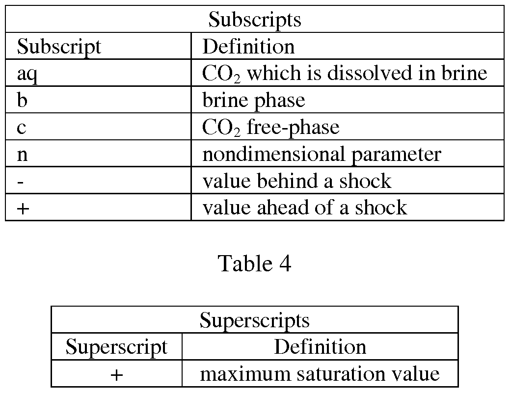
In the following detailed description, all parameters, subscripts, and superscripts may be understood to be defined as listed in the following Table 2, Table 3 and Table 4.
Table 2

Table 3
III. EQUATIONS AND ANALYTIC SOLUTION IN THE ABSENCE OF DISSOLUTION A. Defining the Governing Equations
In order to define the governing equations, the following assumptions were made about the subsurface geologic formation: (1) permeability is isotropic; (2) pressure gradients in the vertical direction are negligible compared with pressure gradients in the horizontal direction; and (3) capillary pressures are negligible in the nonwetting phase. Under these assumptions, a total flow rate leaving an injection well and entering a subsurface geologic formation was defined as the sum of the C02 flow rate and the brine flow rate, and was simply expressed as:
A * u ... =—KA— — -¾-— Eq. 1
Eq. 1 was used to solve for the pressure gradient given by:

The velocity of the C02 phase was written using Darcy' s Law. Since, the pressure gradient in the C02 phase was assumed to be equal to the pressure gradient in the water phase, Eq. 2 was substituted into Eq. 3.

The C02 velocity was then nondimensionalized by dividing both sides of Eq. 3 by QTOTIA.
Simplifying this new equation yielded equation 4a. From Eq. 1, it was also shown that the nondimensional velocity of the brine phase can be written as Eq. 4b.
Eq. 4a
Eq. 4b
In Eq. 4a and Eq. 4b, η and/ are defined in Eq. 5a and Eq. 5b, respectively.
Eq. 5a
Eq. 5b
B. Solving Using the Method of Characteristics
One may turn now to a different governing equation for this same problem: conservation of mass using the definition of saturation to keep track of each phase. The density of each phase was assumed to be constant and the each fluid phase was assumed to be incompressible. These assumptions are consistent with the assumptions made above. Under these assumptions, the conservation of mass for phase i was written as:
— - -i tu*A = 0 Eq. 6
St · 3.s ' ^ J
The second term on the left hand side of Eq. 6 is the saturation convection. The velocity (udd is the Darcy velocity for whichever phase is being considered, and, is generally an implicit function of saturation due to the relative permeability term. Therefore using the chain rule, Eq. 6 is written as Eq. 7. Eq. 7 is more convenient because this partial differential equation now has the form necessary to solve by the method of characteristics.

Using the method of characteristics, the partial differential equation in equation 7 was converted into a coupled set of ordinary differential equations, written in Eq. 8a and Eq. 8b. Eq. 8a shows that the rate of change in saturation with respect to time is zero, provided that an observer of the
saturation function moves along the function with a velocity (v;) given by Eq. 8b. In other words, along a characteristic, the saturation is constant.
0 Eq. 8a dt

The characteristic velocity (v;) can also be nondimensionalized by dividing each side by Qtot/A. The results were substituted from Eq. 4a, Eq. 5a and Eq. 5b to write Eq. 9, which is the nondimensional characteristic velocity for the C02 phase.
Finally, Eq. 9 was used to evaluate duncldf ' Eq. 4. Doing so yields the following result:
Eq. 10 is the generalized nondimensional form of the characteristic velocity for the C02 phase. As defined above, this characteristic velocity is the velocity required to observe a control volume which has a constant saturation value. However, Eq. 10 cannot be evaluated without knowing the relative permeability function, f(Sc). If this function were known, it could be substituted into Eq. 10 and the characteristic velocities would be completely defined.
C. Defining Relative Permeability of C02 and H20 in the Subsurface Geologic Formation Relative permeability curves exist for a variety of fluid combinations and rock types. There is no general equation that can be derived for these curves; they all must be empirically determined and then fit with a suitable function. However, the relative permeability curves tend to look like
FIG. 2.
For purposes of this analysis, the relative permeability curves were approximated by linear functions of Sc defined in Eq. 11a and Eq. 1 lb, where the and S~ are the residual saturations of brine and C02, respectively. k_is -] = ^-s£_ Eq. 11a
k {S. ) = ^ Eq. l ib
The nondimensional governing equations with and without knowing the functional form for the relative permeabilities of each phase are summarized in Table 5
Table 5

IV. MACROSCALE PUMPING CONSIDERATIONS
As discussed previously, one embodiment of a method of filling a carbon dioxide storage reservoir in the form of a subsurface geologic formation includes periodically injecting brine behind the C02 in a free-phase C02 plume in an effort to immobilize the C02 in the free-phase plume in the subsurface geologic formation, concurrent with the injection. This immobilization can be accomplished by at least two separate mechanisms: trapping and dissolution. Each mechanism requires different ratios of brine to C02, and, consequently, a different reservoir volume.
Aspects of the first mechanism, trapping, are shown in FIG. 1(c). C02 is immobilized in the pore spaces of a porous rock formation within a subsurface geologic formation at low volume
fractions when surrounded by and compressed by brine. In a sense, the compressing brine "smears" the free-phase C02 out over a larger subsurface geologic formation area. The volume ratio required for a first cycle is given by Eq. 12. After the first cycle, a slightly different volume ratio is required, and is defined by Eq. 13. The difference between the two equations derives from the observation that during the first injection of C02, the C02 is penetrating undisturbed brine. Within all following injections of C02> the injected C02 is entering a zone which already contains C02.
Ϊ-5 l-¾ !i , D→Q
Γ---1 Eq. 12
When dissolution is neglected, the extent of C02 presence after "Λ injection cycles in a simple 2D domain is then given by equation 14, and for the radially symmetric 3D domain is then given by equation 15.
L'„ =— ^ Eq. 14 ;v.
R = Eq. 15
The second mechanism, dissolution, requires all of the free-phase C02 within the mobile C02 plume to be dissolved into the available quantity of brine. Similar to the trapping strategy, volume ratios required for the first cycle and all following cycles are given by Eq. 16 and Eq. 17, respectively. The extent of the C02 presence in the reservoir for 2D and 3D domains are given by Eq. 18 and Eq. 19, respectively, for the option of complete dissolution.
 γΩ = - Eq. 17
Ri: = τΗφΩ, Eq. 19
γΩ = - Eq. 17
Ri: = τΗφΩ, Eq. 19
By taking advantage of a capillary trapping mechanism for free-phase C02 immobilization and/or a dissolution mechanism for free-phase C02 immobilization, it is anticipated within the context of the prophetic computer simulations in accordance with the embodiments that the free- phase C02 will be completely immobilized at the end of the last brine injection.
V. SUMMARY OF RESULTS AND COMPARISON TO COMMERCIAL SOFTWARE A. Analytic Predictions
The preceding analysis and equations are valid for any variation of the periodic injection strategy as currently embodied or contemplated to be embodied. However, in order to compare results, the representative values listed in Table 6 were used for macroscale pumping estimates, and some assumptions were made about the mass of C02 being sequestered. Table 1 compares some of the key results of the present embodiments in comparison with a traditional single injection strategy. For all of the cases analyzed, all of the C02 emissions from a 1 GW coal-fired power plant operating for 1 year had to be sequestered in a carbon dioxide storage reservoir of 10 meter height.
Table 6

As indicated above, Table 1 shows a summary of results comparing the dissolution and trapping mechanisms of the embodiments to the traditional strategy when sequestering all of the C02
emissions from the 1 GW coal-fired power plant for 1 year. The best/worst case values were found by minimizing/maximizing the 4 parameters provided whose value is listed as a range in Table 6. This procedure was done independently for the volume ratio results and for the radial extent results, which is to say that the "best" value for volume ratio does not correspond to the same input parameters as the "best" value for radial extent. However, all the values in the "avg." columns used the same input parameters (Caq,sat = 40, pc = 700, S ~ = 0.3, Sj = 0.9). Table 7 shows a pilot-scale simulation of the present embodiment compared to the traditional injection strategy at the end of the last fluid injection (at the 12 day mark for the traditional strategy, at the 44.46 day mark for the trapping strategy, and at the 360 day mark for the dissolving strategy).
Table 7

FIG. 4a, FIG. 4b, FIG. 4c and FIG. 4d show the simulation of the present embodiment, which were taken after the first injection of C02 was complete, and brine was injected. Each figure represents a progression of dissolution of the C02 into the brine. FIG. 4a represents the dissolution directly after the injection of brine, with each intermediate figure representing further dissolution until FIG. 4d represents the end of the first brine injection. The well is located at the left boundary of each figure, causing the fluids to convect towards the right. The color map identifies the location and density of the free-phase C02 (red = most dense gas and highest on gray scale, blue = no gas phase present and lowest on gray scale). As brine is injected, the C02 dissolves into the brine. The original C02 is nearly completely dissolved. This process is repeated 4 times over the course of 1 year.
As shown in FIG. 5, and according to another embodiment, an embodiment may comprise comprise a system having an injection well adapted for sequential injection of brine and C02, and an extraction well for the extraction of brine. The injection well may be any injection well known in the art, as is commonly used to inject C02 into subsurface geologic formations, so long as the well is adapted or otherwise configured to inject at least one injection of C02, and to inject at least one injection of brine. The extraction well is any extraction well known in the art suitable for the extraction of brine from a subsurface geologic formation. As previously stated, the extraction of brine may occur prior to, during, or after the beginning of injection of C02. The extracted brine may be extracted from the same subsurface geologic formation or a separate formation. Furthermore, as previously stated, the subsurface geologic formation may comprise a carbon dioxide impervious caprock formation, a brine impervious baserock formation, and a carbon dioxide porous intermediate rock formation. The system may be further adapted to inject ratios of C02 and brine suited for trapping the C02 in the porous intermediate rock formation as described in the embodiments and calculations above, or may be adapted to inject ratios of C02 and brine suited for the dissolution of C02 within the brine as described in the embodiments and calculations above. In yet an alternative embodiment, the system may be adapted for injecting a ratio of C02 and brine which is calculated to take advantage of both the trapping and dissolution mechanisms.
All references, including publications, patent applications, and patents cited herein are hereby incorporated by reference in their entireties to the extent allowed, and as if each reference was individually and specifically indicated to be incorporated by reference and was set forth in its entirety herein.
The use of the terms "a" and "an" and "the" and similar referents in the context of describing the invention (especially in the context of the following claims) is to be construed to cover both the singular and the plural, unless otherwise indicated herein or clearly contradicted by context. The terms "comprising," "having," "including," and "containing" are to be construed as open-ended terms (i.e., meaning "including, but not limited to,") unless otherwise noted. The term
"connected" is to be construed as partly or wholly contained within, attached to, or joined together, even if there is something intervening.
The recitation of ranges of values herein is merely intended to serve as a shorthand method of referring individually to each separate value falling within the range, unless otherwise indicated herein, and each separate value is incorporated into the specification as if it was individually recited herein.
All methods described herein may be performed in any suitable order unless otherwise indicated herein or otherwise clearly contradicted by context. The use of any and all examples, or exemplary language (e.g., "such as") provided herein, is intended merely to better illuminate embodiments of the invention and does not impose a limitation on the scope of the invention unless otherwise claimed.
No language in the specification should be construed as indicating any non-claimed element as essential to the practice of the invention.
It will be apparent to those skilled in the art that various modifications and variations can be made to the present invention without departing from the spirit and scope of the invention. There is no intention to limit the invention to the specific form or forms disclosed, but on the contrary, the intention is to cover all modifications, alternative constructions, and equivalents falling within the spirit and scope of the invention, as defined in the appended claims. Thus, it is intended that the present invention cover the modifications and variations of this invention provided they come within the scope of the appended claims and their equivalents.
Claims
1. A carbon dioxide storage reservoir comprising:
a subsurface geologic formation; and
an artificially introduced carbon dioxide plume at least in part contacting a quantity of brine, each located within the subsurface geologic formation, wherein the artificially introduced carbon dioxide plume is substantially immobile within the subsurface geologic formation when the quantity of brine is quiescent within the subsurface geologic formation.
2. The carbon dioxide storage reservoir of claim 1 wherein the subsurface geologic formation comprises:
a carbon dioxide impervious cap rock formation;
a brine impervious base rock formation separated from and beneath the carbon dioxide impervious cap rock formation;
a carbon dioxide porous intermediate rock formation interposed between the carbon dioxide impervious cap rock formation and the brine impervious base rock formation; and
a quantity of brine at least partially filling the carbon dioxide porous intermediate rock formation.
3. The carbon dioxide storage reservoir of claim 2 wherein the carbon dioxide storage reservoir further comprises:
an injection well reaching the carbon dioxide porous intermediate rock formation; and an extraction well reaching the quantity of brine.
4. A carbon dioxide storage reservoir comprising:
a subsurface geologic formation including a quantity of brine;
an injection well reaching the subsurface geologic formation and adapted to sequentially and separately inject carbon dioxide and brine into the subsurface geologic formation; and
an extraction well reaching the quantity of brine.
5. A carbon dioxide storage reservoir comprising:
a subsurface geologic formation including:
a carbon dioxide impervious cap rock formation;
a brine impervious base rock formation separated from and beneath the carbon dioxide impervious cap rock formation;
a carbon dioxide porous intermediate rock formation interposed between the carbon dioxide impervious cap rock formation and the brine impervious base rock formation; and
a quantity of brine at least partially filling the carbon dioxide porous intermediate rock formation;
an injection well reaching the carbon dioxide porous intermediate rock formation and being adapted for sequentially and separately injecting carbon dioxide and brine; and
an extraction well reaching the quantity of brine.
6. A method for filling a carbon dioxide storage reservoir comprising:
providing an injection well and an extraction well reaching a subsurface geologic formation;
injecting a quantity of injected carbon dioxide at the injection well and extracting a quantity of extracted brine at the extraction well; and then
injecting a quantity of injected brine at the injection well.
7. A method for filling a carbon dioxide storage reservoir comprising:
providing an injection well and an extraction well reaching a subsurface geologic formation, the subsurface geologic formation including:
a carbon dioxide impervious cap rock formation;
a brine impervious base rock formation separated from and beneath the carbon dioxide impervious cap rock formation;
a carbon dioxide porous intermediate rock formation interposed between the carbon dioxide impervious cap rock formation and the brine impervious base rock formation; and
a quantity of brine at least partially filling the carbon dioxide porous intermediate rock formation; wherein the injection well extends to the carbon dioxide porous intermediate rock formation and the extraction well extends to the quantity of brine; injecting a quantity of injected carbon dioxide at the injection well and extracting a quantity of extracted brine at the extraction well; and then
injecting a quantity of injected brine at the injection well.
8. The method of claim 7 wherein the quantity of injected carbon dioxide is injected before extracting the quantity of extracted brine.
9. The method of claim 7 wherein the quantity of injected carbon dioxide is injected
simultaneous with extracting the quantity of extracted brine.
10. The method of claim 7 wherein the quantity of injected carbon dioxide is injected after extracting the quantity of extracted brine.
11. The method of claim 7 wherein:
a volume ratio of a volume of injected brine to a volume of injected carbon dioxide is from about 2: 1 to about 3: 1; and
the method uses a trapping assumption when filling the carbon dioxide storage reservoir.
12. The method of claim 11 wherein a volume ratio of extracted brine to a volume of injected brine is about 1: 1.
13. The method of claim 7 wherein:
a volume ratio of a volume of injected brine to a volume of injected carbon dioxide is from about 9: 1 to about 25: 1; and
the method uses a dissolution assumption when filling the carbon dioxide storage reservoir.
14. The method of claim 11 wherein a volume ratio of extracted brine to a volume of injected brine is about 1: 1.
15. A method for filling a carbon dioxide storage reservoir comprising:
providing an injection well and an extraction well reaching a subsurface geologic formation, the subsurface geologic formation including:
a carbon dioxide impervious cap rock formation;
a brine impervious base rock formation separated from and beneath the carbon dioxide impervious cap rock formation;
a carbon dioxide porous intermediate rock formation interposed between the carbon dioxide impervious cap rock formation and the brine impervious base rock formation; and
a quantity of brine at least partially filling the carbon dioxide porous intermediate rock formation, wherein the injection well extends to the carbon dioxide porous intermediate rock formation and the extraction well extends to the quantity of brine; injecting a quantity of injected carbon dioxide at the injection well and extracting a quantity of extracted brine at the extraction well; and then
injecting a quantity of injected brine at the injection well, wherein a volume ratio of a volume of injected brine to a volume of injected carbon dioxide is from about 2: 1 to about 3: 1; and
the method uses a trapping assumption when filling the carbon dioxide storage reservoir.
16. A system for filling a carbon dioxide storage reservoir comprising:
an injection well reaching a subsurface geologic formation and adapted for sequential and separate injection of carbon dioxide and brine;
an extraction well reaching a subsurface geologic formation; and
a computer programmed to effect the sequential and separate injection of carbon dioxide and brine at the injection well and the extraction of brine at the extraction well.
17. The system of claim 16 wherein the subsurface geologic formation comprises:
a carbon dioxide impervious cap rock formation;
a brine impervious base rock formation separated from and beneath the carbon dioxide impervious cap rock formation;
a carbon dioxide porous intermediate rock formation interposed between the carbon dioxide impervious cap rock formation and the brine impervious base rock formation; and
a quantity of brine at least partially filling the carbon dioxide porous intermediate rock formation, wherein the injection well extends to the carbon dioxide porous intermediate rock formation and the extraction well extends to the quantity of brine.
18. A non-transitory computer-readable storage medium having stored thereon instructions for sequentially and separately injecting carbon dioxide and brine into a subsurface geologic formation reservoir that, when executed by at least one processor, causes the processor to perform steps comprising:
instructing an injection well, reaching the subsurface geologic formation, to sequentially and separately inject carbon dioxide and brine into a subsurface geologic formation; and
instructing an extraction well, reaching a subsurface geologic formation, to extract brine from the subsurface geologic formation.
19. The non-transitory computer-readable storage medium of claim 18 wherein the subsurface geologic formation comprises:
a carbon dioxide impervious cap rock formation;
a brine impervious base rock formation separated from and beneath the carbon dioxide impervious cap rock formation;
a carbon dioxide porous intermediate rock formation interposed between the
carbon dioxide impervious cap rock formation and the brine impervious base rock formation; and
a quantity of brine at least partially filling the carbon dioxide porous intermediate rock, wherein the injection well extends to the carbon dioxide porous intermediate rock formation and the extraction well extends to the quantity of brine.
20. The medium of claim 19 wherein instructing the extraction well comprises dictating the flow rate of the extraction well.
Applications Claiming Priority (2)
| Application Number | Priority Date | Filing Date | Title |
|---|---|---|---|
| US201261733970P | 2012-12-06 | 2012-12-06 | |
| US61/733,970 | 2012-12-06 |
Publications (1)
| Publication Number | Publication Date |
|---|---|
| WO2014089185A1 true WO2014089185A1 (en) | 2014-06-12 |
Family
ID=50883966
Family Applications (1)
| Application Number | Title | Priority Date | Filing Date |
|---|---|---|---|
| PCT/US2013/073079 Ceased WO2014089185A1 (en) | 2012-12-06 | 2013-12-04 | Extraction-injection method for immobilized sub-surface geologic storage of carbon dioxide |
Country Status (1)
| Country | Link |
|---|---|
| WO (1) | WO2014089185A1 (en) |
Cited By (6)
| Publication number | Priority date | Publication date | Assignee | Title |
|---|---|---|---|---|
| CN114109324A (en) * | 2020-08-28 | 2022-03-01 | 中国石油天然气股份有限公司 | Method and device for determining well shut-in time |
| CN115902160A (en) * | 2022-11-28 | 2023-04-04 | 新疆敦华绿碳技术股份有限公司 | Evaluation of CO in saline water reservoir geology 2 Method for sequestration of potential |
| KR102519877B1 (en) * | 2022-11-14 | 2023-04-11 | 주식회사 지오그린21 | Experimental system and method for a carbon dioxide storage with water pumping |
| CN116255198A (en) * | 2023-02-13 | 2023-06-13 | 大连理工大学 | Carbon dioxide sequestration method based on optimal design of reservoir wettability and layered regulation |
| US12049805B2 (en) | 2022-12-15 | 2024-07-30 | Saudi Arabian Oil Company | Bottom-up sequestration of carbon dioxide in negative geologic closures |
| US20250283391A1 (en) * | 2024-03-05 | 2025-09-11 | Saudi Arabian Oil Company | Carbon dioxide mineralization and storage |
Citations (5)
| Publication number | Priority date | Publication date | Assignee | Title |
|---|---|---|---|---|
| CN101190743A (en) * | 2007-11-30 | 2008-06-04 | 中国科学院武汉岩土力学研究所 | Carbon dioxide geological storage method based on self-separation of mixed fluid |
| US20110013986A1 (en) * | 2009-07-20 | 2011-01-20 | Zebrowski Daniel R | Method For Sequestering Carbon Dioxide In Geological Formations |
| JP2011031154A (en) * | 2009-07-31 | 2011-02-17 | National Institute Of Advanced Industrial Science & Technology | Storage of carbon dioxide in shallow aquifer |
| WO2012041926A2 (en) * | 2010-09-29 | 2012-04-05 | Statoil Asa | Methods for storing carbon dioxide compositions in subterranean geological formations and an apparatus for carrying out the method |
| US8316955B2 (en) * | 2009-03-13 | 2012-11-27 | Regents Of The University Of Minnesota | Carbon dioxide-based geothermal energy generation systems and methods related thereto |
-
2013
- 2013-12-04 WO PCT/US2013/073079 patent/WO2014089185A1/en not_active Ceased
Patent Citations (5)
| Publication number | Priority date | Publication date | Assignee | Title |
|---|---|---|---|---|
| CN101190743A (en) * | 2007-11-30 | 2008-06-04 | 中国科学院武汉岩土力学研究所 | Carbon dioxide geological storage method based on self-separation of mixed fluid |
| US8316955B2 (en) * | 2009-03-13 | 2012-11-27 | Regents Of The University Of Minnesota | Carbon dioxide-based geothermal energy generation systems and methods related thereto |
| US20110013986A1 (en) * | 2009-07-20 | 2011-01-20 | Zebrowski Daniel R | Method For Sequestering Carbon Dioxide In Geological Formations |
| JP2011031154A (en) * | 2009-07-31 | 2011-02-17 | National Institute Of Advanced Industrial Science & Technology | Storage of carbon dioxide in shallow aquifer |
| WO2012041926A2 (en) * | 2010-09-29 | 2012-04-05 | Statoil Asa | Methods for storing carbon dioxide compositions in subterranean geological formations and an apparatus for carrying out the method |
Cited By (10)
| Publication number | Priority date | Publication date | Assignee | Title |
|---|---|---|---|---|
| CN114109324A (en) * | 2020-08-28 | 2022-03-01 | 中国石油天然气股份有限公司 | Method and device for determining well shut-in time |
| CN114109324B (en) * | 2020-08-28 | 2023-09-26 | 中国石油天然气股份有限公司 | Method and device for determining well shut-in time |
| KR102519877B1 (en) * | 2022-11-14 | 2023-04-11 | 주식회사 지오그린21 | Experimental system and method for a carbon dioxide storage with water pumping |
| CN115902160A (en) * | 2022-11-28 | 2023-04-04 | 新疆敦华绿碳技术股份有限公司 | Evaluation of CO in saline water reservoir geology 2 Method for sequestration of potential |
| CN115902160B (en) * | 2022-11-28 | 2024-04-09 | 新疆敦华绿碳技术股份有限公司 | Evaluation of CO in brine layer geology 2 Method for storing potential |
| US12049805B2 (en) | 2022-12-15 | 2024-07-30 | Saudi Arabian Oil Company | Bottom-up sequestration of carbon dioxide in negative geologic closures |
| CN116255198A (en) * | 2023-02-13 | 2023-06-13 | 大连理工大学 | Carbon dioxide sequestration method based on optimal design of reservoir wettability and layered regulation |
| CN116255198B (en) * | 2023-02-13 | 2023-10-13 | 大连理工大学 | Carbon dioxide storage method based on reservoir wettability optimization design and layered control |
| US20250283391A1 (en) * | 2024-03-05 | 2025-09-11 | Saudi Arabian Oil Company | Carbon dioxide mineralization and storage |
| US12467339B2 (en) * | 2024-03-05 | 2025-11-11 | Saudi Arabian Oil Company | Carbon dioxide mineralization and storage |
Similar Documents
| Publication | Publication Date | Title |
|---|---|---|
| Doughty et al. | Modeling supercritical carbon dioxide injection in heterogeneous porous media | |
| Ajayi et al. | Large scale modeling and assessment of the feasibility of CO2 storage onshore Abu Dhabi | |
| Qi et al. | Design of carbon dioxide storage in aquifers | |
| Ozdemir | Modeling of coal bed methane (CBM) production and CO2 sequestration in coal seams | |
| WO2014089185A1 (en) | Extraction-injection method for immobilized sub-surface geologic storage of carbon dioxide | |
| Flett et al. | The function of gas-water relative permeability hysteresis in the sequestration of carbon dioxide in saline formations | |
| Solomon et al. | Intermediate storage of carbon dioxide in geological formations: A technical perspective | |
| US20130064604A1 (en) | Methods and systems for co2 sequestration | |
| Afanasyev | Application of the reservoir simulator MUFITS for 3D modelling of CO2 storage in geological formations | |
| Pool et al. | Dynamics and design of systems for geological storage of dissolved CO2 | |
| Van der Meer et al. | Limitations to storage pressure in finite saline aquifers and the effect of CO2 solubility on storage pressure | |
| Oldenburg et al. | Injection, flow, and mixing of CO2 in porous media with residual gas | |
| Connell et al. | Nitrogen enhanced drainage of CO2 rich coal seams for mining | |
| Khoramian et al. | The role of Capillary Hysteresis in Enhancing CO₂ Trapping Efficiency and Storage Stability | |
| Qi et al. | Design of carbon dioxide storage in a North Sea aquifer using streamline-based simulation | |
| Montero et al. | Assessing the impact of sedimentary heterogeneity on CO2 injection in fluvial meander-belt successions using geostatistical modelling informed by geological analogues | |
| March et al. | accurate dual-porosity modeling of co2 storage in fractured reservoirs | |
| Akinnikawe et al. | Geologic model and fluid flow simulation of Woodbine aquifer CO2 sequestration | |
| Tao et al. | Optimal control of injection/extraction wells for the surface dissolution CO2 storage strategy | |
| Huber et al. | Analysis of a time dependent injection strategy to accelerate the residual trapping of sequestered CO2 in the geologic subsurface | |
| Wang et al. | Global sensitivity analysis of CO2 storage in fractured aquifers via computer experiments | |
| Shi et al. | A new method based on boundary element method to appraise CO2 geological storage potential in depleted shale gas reservoirs | |
| Ghoodjani et al. | Numerical and Analytical Optimization of Injection Rate During CO2-EOR and-Sequestration Processes | |
| Schwartz | The spatial-temporal influence of grouped variables on pressure plume behavior at a geologic carbon storage project | |
| Stein et al. | CO2 sequestration in a depleted gas field: A material balance study |
Legal Events
| Date | Code | Title | Description |
|---|---|---|---|
| 121 | Ep: the epo has been informed by wipo that ep was designated in this application |
Ref document number: 13860573 Country of ref document: EP Kind code of ref document: A1 |
|
| NENP | Non-entry into the national phase |
Ref country code: DE |
|
| 122 | Ep: pct application non-entry in european phase |
Ref document number: 13860573 Country of ref document: EP Kind code of ref document: A1 |