WO2014087496A1 - グラフ処理方法、および情報処理システム - Google Patents
グラフ処理方法、および情報処理システム Download PDFInfo
- Publication number
- WO2014087496A1 WO2014087496A1 PCT/JP2012/081447 JP2012081447W WO2014087496A1 WO 2014087496 A1 WO2014087496 A1 WO 2014087496A1 JP 2012081447 W JP2012081447 W JP 2012081447W WO 2014087496 A1 WO2014087496 A1 WO 2014087496A1
- Authority
- WO
- WIPO (PCT)
- Prior art keywords
- vertices
- vertex
- graph
- processes
- information processing
- Prior art date
- Legal status (The legal status is an assumption and is not a legal conclusion. Google has not performed a legal analysis and makes no representation as to the accuracy of the status listed.)
- Ceased
Links
Images






Classifications
-
- G—PHYSICS
- G06—COMPUTING OR CALCULATING; COUNTING
- G06F—ELECTRIC DIGITAL DATA PROCESSING
- G06F9/00—Arrangements for program control, e.g. control units
- G06F9/06—Arrangements for program control, e.g. control units using stored programs, i.e. using an internal store of processing equipment to receive or retain programs
- G06F9/46—Multiprogramming arrangements
- G06F9/50—Allocation of resources, e.g. of the central processing unit [CPU]
- G06F9/5061—Partitioning or combining of resources
- G06F9/5066—Algorithms for mapping a plurality of inter-dependent sub-tasks onto a plurality of physical CPUs
Definitions
- the present invention relates to graph processing in a parallel computer system.
- Non-patent literature In order to perform large-scale graph analysis at high speed, it is common to divide graph data into multiple groups (clusters) and then place each in a single process to execute parallel processing (non-patent literature) 1).
- This data division method is known as a clustering technique, and a typical technique is disclosed in Non-Patent Document 2.
- a process before performing data division a plurality of vertex data is collected and converted into a small size graph, and the number of vertices in each cluster with respect to the converted graph Are divided so that the number of edges between the clusters is as small as possible. Then, desired data division is realized by inversely transforming the divided graph data.
- a graph having a scale-free characteristic is a graph in which the degree distribution follows a power. Composed.
- the degree of the degree of the hub vertex having the maximum degree may be several percent of the total number of vertices in the graph.
- graph analysis mainly calculates feature quantities of the target graph, for example, graph diameter, centrality, principal component vector by random walk, etc., and these feature quantities are calculated along the edges between the vertices.
- Information exchange processing (traverse processing) accounts for the majority. In this traversing process, the order of the vertices greatly affects the calculation time.
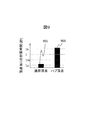
- FIG. 9 shows an example of the relationship between the order and calculation time. As shown in FIG. 9, the calculation time 900 of the hub having many orders is several orders of magnitude longer than the calculation time 901 of the normal vertex having the average order.
- the number of vertices of each cluster is equalized, but no order is taken into consideration. Therefore, a large deviation occurs in the total order in each cluster, and there is a problem that efficient parallel processing cannot be performed and calculation time becomes long.
- the conventional technique has a problem that due to the scale-free characteristics of the input graph, data arrangement that equalizes the calculation amount of each process cannot be performed, and efficient parallel calculation cannot be provided.
- an object of the present invention is to provide an efficient parallel calculation by leveling the calculation amount of each process.
- the present invention is a parallel computer system that executes a plurality of processes each of which is allocated a memory space, reads out graph structure data stored in a storage, and has a higher degree in the read graph structure data
- the above-mentioned problem is solved by extracting the vertices, arranging the extracted vertices in a distributed manner in a plurality of processes, and calculating each of the vertices arranged in each process.
- the calculation amount of the parallel computer is leveled, and efficient parallel processing can be realized.
- FIG. 1 shows an information processing system 100 which is a parallel computer system according to an embodiment of the present invention.
- the information processing system 100 includes a management node 101, calculation nodes 102-1 to 102-3, a storage system 103, a management node 101, calculation nodes 102-1 to 102-3, and a network 104 that connects the storage systems.
- three calculation nodes 102-1 to 10-3 are shown as an example in the present embodiment.
- one or more calculation nodes may be used.
- each of the management node 101 and the computation nodes 102-1 to 102-3 is a server device.
- the calculation node 102-1 may be referred to as the calculation node 1, the calculation node 102-2 as the calculation node 2, and the calculation node 102-3 as the calculation node 3.
- Each of the computation nodes 102-1 to 10-3 includes a processor unit 105, a memory unit 107, a communication unit 108, and a bus 109.
- the processor unit 105 includes central processing units (CPUs) 106-1 to 106-1. In the present embodiment, the processor unit 105 has four CPUs. However, the processor unit 105 may have one or more CPUs.
- a bus 109 connects the processor unit 105, the memory unit 107, and the communication unit 108.
- the management node 101 can have the same unit configuration as the computation nodes 102-1 to 102-3.
- the management node 101 is responsible for processing to place an input graph in each process.
- Each process is operated by one or more CPUs on the calculation nodes 102-1 to 102-3, and a memory space corresponding to each process is secured in one or more memory units.
- One CPU may process a plurality of processes, and one memory unit may hold a memory space of a plurality of processes.
- An arithmetic unit such as a field programmable gate array (FPGA) or a graphic processing unit (GPU) may be used instead of the CPU.
- FPGA field programmable gate array
- GPU graphic processing unit
- the processor unit 105 can access a unit group such as the memory unit 107 in another calculation node via the communication unit 108. Similarly, the processor unit 105 can access information stored in the storage system 103 via the communication unit 108.
- FIG. 2 shows a functional configuration diagram of the information processing system 100.
- the storage system 103 stores input graph data 201 for performing graph analysis.
- the input graph data 201 is data having a graph structure.
- the storage system 103 includes a data input / output unit 202 that exchanges data with the management node 101 and the computation nodes 102-1 to 102-3 via the network 104.
- the storage system 103 also has a storage device that stores data such as input graph data 201.
- the management node 101 includes a data input unit 203 and a data output unit 206 that exchange data with the computation nodes 102-1 to 10-3 and the storage system 103 via the network 104.
- the management node 101 distributes the input graph data 201 acquired from the storage system 103 to each calculation node, so that a vertex placement destination process determination unit 204 that determines a placement destination process for each vertex and a placement destination process determination unit 204.
- the process management data 205 representing the correspondence between the placement destination process and the placement destination computation node of each vertex determined in step (2), and the normal vertex list 214 for storing information of vertices having a relatively low degree in the input graph data 201. .
- the calculation nodes 102-1 to 10-3 include a data input unit 207 and a data output unit 213 that exchange data with the management node 101, other calculation nodes, and the storage system 103 via the network 104.
- the calculation nodes 102-1 to 102-3 further process the vertex connection information 208 transmitted from the management node 101, the vertex component data 209, the adjacent vertex process indicating the correspondence between the vertex in the vertex connection information and its execution process.
- FIG. 3 is an example (graph 1) of a part of the input graph of the present invention.
- vertices are represented by circles, and directed edges are represented by arrows connecting the vertices.
- a vertex connected by a directed edge, and a vertex at the arrow destination as viewed from the vertex at the arrow source is called “adjacent”.
- a vertex having an order greater than 1000 is set as a hub vertex.
- the component data held by each vertex is distributed to adjacent vertices, and each vertex receives the distributed component data, performs a sum operation, and repeats the process of updating the component data of each vertex. Is done. And the component data which each vertex hold
- the component data of the vertex v14 itself at time t-1 is distributed to adjacent vertices (v10 and v27).
- to distribute means to transmit by dividing by the number of adjacent vertices, here two. This calculation is described in Equation (1).
- D represents component data
- sendD represents component data to be distributed
- the suffix on the right shoulder represents time
- parentheses represent target vertex identification information (vertex ID).
- the distributed component data (sendD) is received from adjacent vertices (v15 to v20), and the sum is calculated.
- a formula for this calculation is shown in Formula (2). The result of the calculated sum is component data at time t.
- sendD (v14) t-1 D (v14) t-1 / (Number of outdegrees of vertex v14) Formula (1)
- the component data held by each vertex is output.
- the graph 1 is arranged in a plurality of processes generated in each computation node and parallel processing is performed.
- the calculation amount of the equation (1) depends on the number of edges of the graph 1
- the calculation amount of the equation (2) depends on the number of vertices.
- the calculation amount of the formula (1) is more dominant than the calculation amount of the formula (2). Therefore, in the process arrangement of graph data, if the number of vertices is arranged so as to be equal as in the technique disclosed in Non-Patent Document 2, a large deviation occurs in the calculation amount of each process, and efficient parallel processing is performed. It cannot be done and the calculation time will be long.
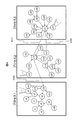
- FIG. 4 is a conceptual diagram showing a state in which the graph 1 is arranged in the process 1, the process 2, and the process 3 of the three processes in the information processing system 100.
- edges hereinafter referred to as interprocess edges
- Communication between computation nodes generally has a larger transmission delay than communication within a computation node. If the arrangement is such that communication between processes is increased, the communication partner process does not necessarily exist in the same calculation node, so that the communication between calculation nodes also increases.
- the inventors of the present application thought that it is desirable to perform data arrangement so that the number of inter-process edges is reduced. Further, as described above, since the graph having the scale-free characteristic has hub vertices, it was considered desirable to assign the hub vertices to different processes in order to equalize the number of edges. Furthermore, the inventors of the present application have thought that it is desirable to arrange vertices that are already arranged in each process and vertices adjacent to each process in order to reduce the number of edges between processes. Based on these considerations, in the present embodiment, first, a vertex having a large degree is placed in each process in the graph to be processed.
- the total order the sum of the orders of the vertices arranged in each process (hereinafter referred to as the total order) is confirmed, and the vertices are added to the process having the smallest total order. Furthermore, in this embodiment, when a vertex is added to a process having the smallest total degree, a vertex adjacent to a vertex already arranged in the process is selected as the vertex to be added.
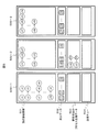
- FIG. 5 shows a memory space (memory space 1 (500-1) corresponding to process 1; memory space 2 (500-2) corresponding to process 2; And the memory contents (vertex connection information 501, component data 502, process management data 503 of adjacent vertices, and transmission queue 504).
- characters in circles stored in the vertex connection information 501 indicate vertex IDs
- arrows indicate information on adjacent relations, and indicate that the arrows are adjacent to the arrow destination.
- a character in the square described in the component data 502 indicates component data (D) possessed by the vertex ID indicated by the character.
- the character in the diamond of the process management data 503 of the adjacent vertex represents the process number (P1 corresponds to the process 1), and indicates that the vertex ID connected by the line segment is assigned to the process having the process number.
- the vertex connection information 501 is included in the vertex connection information 208
- the component data 502 is included in the vertex component data 209
- the process management data 503 for adjacent vertices is included in the process management data 210 for adjacent vertices.
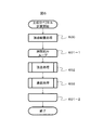
- Fig. 6 shows the processing flow of principal component vector calculation.
- the vertex arrangement processing 600 is first performed.
- the vertex placement process 600 is a process performed by the management node 101.
- the management node 101 accesses the input graph data 201 stored in the storage system 103, and the vertex placement destination process determination unit 204 performs placement of each vertex.
- a process is determined and the process management data 205 is updated.
- FIG. 12 shows an example of the process management data 205.
- the process management data 205 includes, as entries, the vertex ID of the arranged vertex, the information of the process where the vertex is placed, and the information of the calculation node where the process is placed.
- the information in which the vertex whose vertex ID is v1 is arranged in the process 1 executed in the calculation node 1 is an entry.
- the data output unit 206 transmits the vertex connection information, vertex component data, and process management data of adjacent vertices to the placement destination process according to the process management data 205.
- the transmitted vertex connection information is arranged as vertex connection information 501 in a memory space corresponding to the received process.
- the node performs computation by performing vertex processing 602 and communication processing 603 for each vertex.
- the vertex processing 602 is performed by the vertex processing unit 211 of each calculation node, the component data of each vertex is calculated, and the component data 502 in the memory space is updated.
- the update data transmission destination determination unit 212 checks the vertex connection information 501 and the process management data 503 of the adjacent vertex. If the calculated adjacent vertex of the vertex is arranged in another process, the updated component data Is stored in the transmission queue 504.
- component data stored in the transmission queue 504 is communicated between processes via the data output unit 213.
- the communication destination process adds the received component data (sendD) to the component data (D) of the corresponding adjacent vertex. This process follows equation (2).
- FIG. 7 shows a process flow of the vertex arrangement process 600.
- an initial vertex arrangement process 700 is performed.
- hub vertices are extracted from the input graph data 201 stored in the storage system 103, and are distributed and arranged in each process.
- a hub vertex extraction method for example, there is a method of sorting input graphs in descending order and arranging them in a process in descending order.
- a threshold of the order is set in advance by the user, and when a vertex that is larger than the threshold is found during the search of the input graph, it is extracted and used as a hub vertex. In this embodiment, the latter method will be described.
- FIG. 10 shows a flow of the initial vertex arrangement processing 700.
- the initial vertex arrangement processing 700 includes loop processing 1001-1 to 2 for finding the hub vertex from the input graph several times (processing between 1001-1 to 1001-2 is a loop target).
- step 1001 if the vertex placement destination process determination unit 204 is a vertex whose degree is larger than a threshold preset by the user, the process proceeds to step 1002, and the vertex is placed in the process as a hub vertex.
- the process is arranged in the process 1, and the process is arranged in the process 2 at the next opportunity.
- the arrangement of the hub vertices is realized.
- the vertex v9 is arranged in the process 1
- the vertex v21 is arranged in the process 2
- the vertex v37 is arranged in the process 3. If there are only these three processes and there are more hub vertices, they may be arranged again from process 1 again. As described above, the extracted hub vertices can be distributed and arranged in each process.
- the vertex placement destination process determination unit 204 adds the vertex to the normal vertex list 214 in step 1003.
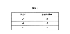
- An example of the normal vertex list 214 is shown in FIG. In the normal vertex list 214, the vertex IDs of the vertices whose order is equal to or lower than the threshold value and the information of the connection destination vertex are added.
- loop processing 701-1 and 2 (between 701-1 and 701-2) for placing one vertex at a time from the remaining input graph data added to the normal vertex list 214.
- each step of process selection 702 and vertex selection 703 is performed.
- process selection 702 the process for placing the vertex next is selected. Specifically, the vertex placement destination process determination unit 204 confirms the total sum (assignment order) of the vertices placed in each process at the time of processing, and selects the process with the smallest assignment order.
- the vertex placement destination process determination unit 204 selects the placed vertexes in the process selected in the process selection 702 based on the process management data 205 from the remaining input graphs in the normal vertex list 214. Adjacent vertices are preferentially selected and placed in the process. Thereby, it is possible to realize an arrangement in which inter-process communication is reduced. More preferably, the vertex placement destination process determination unit 204 is adjacent to the placed vertex in the process selected in the process selection 702 from the remaining input graphs in the normal vertex list 214 and is another in-process vertex. Vertices that are not adjacent to are selected and placed in the process. Thereby, it is possible to realize an arrangement in which inter-process communication is further reduced.
- the user may set a threshold value for the traffic volume between the computation nodes in advance, and the vertex placement destination process determination unit 204 may place the vertex with reference to the process management data 205 so that the threshold falls within the range. it can.
- the data amount of the component data of each vertex is A byte
- the maximum number of edges between calculation nodes of each vertex arranged in each process is N (1).
- N (M) the maximum traffic from the calculation node is ⁇ N (l) ⁇ A.
- the vertex placement destination process decision unit 204 performs data placement of vertices based on the process allocation to the computation nodes, thereby reducing the communication traffic between computation nodes and improving parallel computation efficiency. can do.
- the vertex placement destination process determination unit 204 sets a threshold of traffic between nodes based on the topology of the network 104 and the maximum bandwidth between servers or switches, and within the range. You can also arrange the vertices so that
- the processing time of the graph analysis process is modeled in advance based on the specification information of the information processing system 100.
- the vertex placement destination process determination unit 204 determines from the model. It is also possible to calculate the current processing time of each process and select a process with a short processing time.
- Example 2 shows an example in which vertex selection is performed before process selection 702.
- FIG. 8 shows an intermediate process when the input graph data of FIG. 3 is arranged as shown in FIG. In FIG. 8, the arrangement of the vertex v17 selected in the vertex selection is performed.
- the degree of the vertex v17 is 3, which is adjacent to the process 2 and the process 3 (801-1, 801-2, 801-3).
- the vertex placement destination process 204 places the vertex in a process having a large number of adjacent edges, thereby reducing inter-process communication. Can do.
- vertex v17 is placed in process 2.
- 100 Information processing system
- 101 Management node, 102-1 to 3: Computing node
- 103 Storage system
- 104 Network
- 105 Processor unit
- 106-1 to 4 CPU
- 107 Memory unit
- 108 Communication Unit:
- 201 Input graph data
- 202 Data input / output unit
- 204 Vertex placement destination process decision unit
- 205 Process management data
- 207 Data input unit
- 208 Vertex connection Information
- 209 vertex component data
- 210 process management data of adjacent vertices
- 211 vertex processing unit
- 212 update data transmission destination determining unit
- 213 data output unit
- 214 normal vertex list.
Landscapes
- Engineering & Computer Science (AREA)
- Software Systems (AREA)
- Theoretical Computer Science (AREA)
- Physics & Mathematics (AREA)
- General Engineering & Computer Science (AREA)
- General Physics & Mathematics (AREA)
- Multi Processors (AREA)
Abstract
入力グラフが有するスケールフリー特性により、各プロセスの計算量が均等化するようなデータ配置ができず、効率的な並列計算を提供できないという課題がある。 本発明は、それぞれにメモリ空間が割当てられている複数のプロセスを実行する並列計算機システムで、ストレージに記憶されているグラフ構造データを読み出し、読み出されたグラフ構造データの内で、次数の大きい頂点を抽出し、抽出した頂点を複数のプロセスに分散して配置し、各プロセスが各プロセスに配置された頂点について演算することで、前述の課題を解決する。
Description
本発明は、並列計算機システムでのグラフ処理に関する。
インターネットなどの通信技術の進歩とストレージ技術向上に伴う記録密度増大により、企業や個人が扱うデータ量が大きく増加し、近年はその大規模なデータの繋がり(ネットワークとも呼ばれる)を解析することが重要になってきた。
特に、人間関係などの自然界で生じるデータの繋がりには、スケールフリーと呼ばれる特性を有するグラフが多く、このスケールフリー特性を有する大規模グラフの解析が重要になってきた(特許文献1)。
大規模グラフ解析を高速に行うためには、グラフデータを複数のグループ(クラスタ)に分割した後、それぞれを単一のプロセスに配置し並列処理を実行するのが一般的である(非特許文献1)。このデータ分割方法はクラスタリング技術として知られており、代表的なものに非特許文献2に開示された技術がある。非特許文献2に開示された技術では、データ分割を行う前の処理として、複数の頂点データが纏められて小さいサイズのグラフに変換され、その変換されたグラフに対して各クラスタ内の頂点数が均等でかつクラスタ間のエッジ数ができるだけ少なくなるようにグラフデータが分割される。そして、分割後のグラフデータが逆変換されることで所望のデータ分割が実現される。
ダグラス・グレガー(Douglas Gregor)、アンドルー・ラムスデン(Andrew Lumsdaine)、「分散メモリ並列計算のための順次グラフアルゴリズムの排除(Lifting sequential graph algorithms for distributed-memory parallel computation)」、「OOPSLA’05第20回オブジェクト指向プログラミング、システム、言語、アプリケーションに関するACM SIGPLAN年会紀要(OOPSLA ‘05 Proceedings of the 20th annual ACM SIGPLAN conference on Object-oriented programming, systems, languages, and applications」、エイシーエムニューヨーク(ACM New York)、(米国)、2005年、p.423-437
ジョージ・カルピス(GEORGE KARYPIS)、ビピン・クマール(VIPIN KUMAR)、「不規則なグラフの分割のための高速、高品質な複数階層スキーム(A FAST AND HIGH QUALITY MULTILEVEL SCHEME FOR PARTITIONING IRREGULAR GRAPHS)」、SIAM Journal on Scientific Computing、1998年、第20巻、第1号、p.359-392
スケールフリー特性を有するグラフとは次数分布がべき乗に従うグラフであり、少数のエッジを有する多数の頂点と多数のエッジ(大きな次数とも表現する)を有する少数の頂点(これをハブ頂点と称する)で構成される。ここで、最大次数を有するハブ頂点の次数の大きさは、グラフ内全頂点数の数%に上ることもある。
また、グラフ解析は一般に、対象となるグラフの特徴量、例えばグラフ直径、中心性、ランダムウォークによる主成分ベクトルなどの算出が主であり、これら特徴量の算出は、頂点間の辺に沿った情報交換処理(トラバース処理)が多くを占める。このトラバース処理では、頂点の次数が計算時間に大きな影響を及ぼす。図9に、次数と計算時間の関係例を示す。図9に示したように、次数が多いハブの計算時間900は、平均次数を持つ通常頂点の計算時間901より数桁長い。非特許文献2に開示された技術では、各クラスタの頂点数は均等化されるものの、次数は何も考慮されていない。したがって、各クラスタ内の総次数に大きな偏りが生じてしまい、効率的な並列処理が行えず計算時間が長くなるという課題がある。
以上のように、従来技術では、入力グラフが有するスケールフリー特性により、各プロセスの計算量が均等化するようなデータ配置ができず、効率的な並列計算を提供できないという課題がある。
そこで、本発明は、各プロセスの計算量を平準化し、効率的な並列計算を提供することを目的とする。
本発明は、それぞれにメモリ空間が割当てられている複数のプロセスを実行する並列計算機システムで、ストレージに記憶されているグラフ構造データを読み出し、読み出されたグラフ構造データの内で、次数の大きい頂点を抽出し、抽出した頂点を複数のプロセスに分散して配置し、各プロセスが各プロセスに配置された頂点について演算することで、前述の課題を解決する。
本発明により、並列計算機の計算量が平準化され、効率的な並列処理を実現できる。
図1に、本発明の実施例の並列計算機システムである情報処理システム100を示す。情報処理システム100は、管理ノード101と、計算ノード102-1~3と、ストレージシステム103と、管理ノード101、計算ノード102-1~3、およびストレージシステムを接続するネットワーク104とを備える。計算ノードは、本実施例では計算ノード102-1~3の3台を例として示したが、1台以上あれば良い。管理ノード101や計算ノード102-1~3は、例えば、それぞれがサーバ装置である。なお、以下の説明で、計算ノード102-1を計算ノード1、計算ノード102-2を計算ノード2、計算ノード102-3を計算ノード3と呼ぶ場合もある。
計算ノード102-1~3のそれぞれは、プロセッサユニット105と、メモリユニット107と、通信ユニット108と、バス109とを備える。プロセッサユニット105は、中央処理装置(CPU)106-1~4を有する。プロセッサユニット105は、本実施例では4つのCPUを有する例を示したが、1つ以上のCPUを有すれば良い。バス109は、プロセッサユニット105と、メモリユニット107と、通信ユニット108とを接続する。
管理ノード101には、計算ノード102-1~3と同じユニット構成のものを用いることが出来る。管理ノード101は、入力グラフを各プロセスに配置する処理を担う。
各プロセスは、計算ノード102-1~3上の1つ以上のCPUで演算され、各プロセスに対応するメモリ空間は1つ以上のメモリユニットに確保される。また、1つのCPUが複数のプロセスを処理しても良く、1つのメモリユニットが複数のプロセスのメモリ空間を保持しても良い。CPUの代わりにフィールド・プログラマブル・ゲート・アレイ(FPGA)やグラフィック・プロセッシング・ユニット(GPU)などの演算器を用いても良い。
プロセッサユニット105は、通信ユニット108を経由し他の計算ノード内のメモリユニット107などのユニット群にアクセスが出来る。同様に、プロセッサユニット105は、通信ユニット108を経由してストレージシステム103に格納されている情報にアクセスできる。
図2に、情報処理システム100の機能構成図を示す。ストレージシステム103には、グラフ解析を行うための入力グラフデータ201が保存されている。入力グラフデータ201は、グラフ構造を有するデータである。ストレージシステム103は、ネットワーク104を介して管理ノード101および計算ノード102-1~3とデータのやり取りを行うデータ入出力部202を備える。また、ストレージシステム103は、入力グラフデータ201などのデータを保存するストレージデバイスを有する。
管理ノード101は、ネットワーク104を介して計算ノード102-1~3およびストレージシステム103とデータのやり取りを行うデータ入力部203およびデータ出力部206を備える。また、管理ノード101は、ストレージシステム103から取得した入力グラフデータ201を各計算ノードに分散するため、各頂点の配置先プロセスを決定する頂点配置先プロセス決定部204と、配置先プロセス決定部204で決定した各頂点の配置先プロセスおよび配置先計算ノードの対応関係を表したプロセス管理データ205と、入力グラフデータ201の内で次数が比較的小さい頂点の情報を蓄える通常頂点リスト214とを備える。
計算ノード102-1~3は、ネットワーク104を介して管理ノード101、他の計算ノード、およびストレージシステム103とデータのやり取りを行うデータ入力部207およびデータ出力部213を備える。計算ノード102-1~3は、さらに、管理ノード101から送信された頂点接続情報208と、頂点成分データ209と、頂点接続情報内の頂点とその実行プロセスの対応関係を示した隣接頂点のプロセス管理データ210と、アプリケーション毎の所定の頂点計算を行う頂点処理部211と、頂点接続情報208に基づいて、頂点処理によって更新した頂点成分データの送信先を決定する更新データ送信先決定部212とを有する。
情報処理システム100によるグラフ解析処理方法について以下に説明する。図3は、本発明の入力グラフの一部の例(グラフ1)である。グラフ1は、頂点が丸印で、有向エッジが頂点間を結ぶ矢印で表現されている。また有向エッジで繋がった頂点で、矢印元の頂点から見て矢印先の頂点を「隣接する」と呼ぶ。また、本実施例では、次数が1000より大きい頂点をハブ頂点とする。グラフ1では、頂点v9、v21、v37の3つの頂点の次数が1000より大きいとする。
次に、グラフ1に対するグラフ解析処理の例として、ランダムウォークによる主成分ベクトルの計算を考える。この主成分ベクトルの計算は、一般に、各頂点が保持する成分データを隣接する頂点に分配し、各頂点は分配された成分データを受け取り総和演算し、各頂点の成分データを更新する処理を繰り返すことで行われる。そして、複数回繰り返して更新処理を実施した後の各頂点が保持する成分データが主成分ベクトルとなる。
グラフ1の頂点v14においては、まず、頂点v14自身の持つ時刻t-1の成分データを隣接する頂点(v10およびv27)に分配する。ここで、分配するとは、隣接する頂点の数、ここでは2で除算し送信することをいう。この計算を数式(1)に記載する。ここで、Dは成分データ、sendDは分配する成分データを表し、右肩の添え字は時刻、括弧書きは対象とする頂点識別情報(頂点ID)を示す。次に、分配された成分データ(sendD)を隣接される頂点(v15~v20)から受け取り、総和を算出する。この計算の計算式を数式(2)に示す。そして、算出された総和の結果が時刻tの成分データとなる。
sendD(v14)t-1 = D(v14)t-1/(Number of outdegrees of vertex v14)
数式(1)
D(v14)t = Σ{i=v15,v16,v17,v18,v19,v20}sendD(i)t-1
数式(2)
以上の処理を全ての頂点に対し複数回実施した後、各頂点が保持する成分データが出力となる。
sendD(v14)t-1 = D(v14)t-1/(Number of outdegrees of vertex v14)
数式(1)
D(v14)t = Σ{i=v15,v16,v17,v18,v19,v20}sendD(i)t-1
数式(2)
以上の処理を全ての頂点に対し複数回実施した後、各頂点が保持する成分データが出力となる。
情報処理システム100では、グラフ1が各計算ノードに生成された複数のプロセスに配置され並列処理が行われる。ここで、主成分ベクトルの計算では、数式(1)の計算量はグラフ1のエッジ数に依存し、数式(2)の計算量は頂点の数に依存する。スケールフリー特性を有するグラフでは、ハブ頂点が存在するため、数式(1)の計算量が数式(2)の計算量よりも支配的である。したがって、グラフデータのプロセス配置において、非特許文献2に開示された技術のように頂点数が均等になるように配置すると、各プロセスの計算量に大きな偏りが発生し、効率的な並列処理が行えず計算時間が長くなってしまう。
そこで、本発明では、図4に示すように、各プロセス内のエッジ数を均等化するように頂点の各プロセスへの配置を行うことで、各プロセスの計算量を平準化する。図4は、情報処理システム100の内の3つのプロセスのプロセス1、プロセス2、およびプロセス3にグラフ1が配置されている様子を概念図として示したものである。ここで、プロセス間を繋ぐエッジ(以下、プロセス間エッジ)400、401、402は、計算ノード間の通信を表わしている。計算ノード間の通信は、計算ノード内の通信よりも一般的に伝送遅延が大きい。プロセス間通信が増えるような配置をすれば、必ずしも同じ計算ノード内に通信相手のプロセスが存在するわけではないから、計算ノード間通信も増える。したがって、本願発明者らは、プロセス間エッジ数が少なくなるようにデータ配置を行うことが望ましいと考えた。また、前記のとおり、スケールフリー特性をもつグラフはハブ頂点を有しているので、エッジ数を均等化するには、このハブ頂点を異なるプロセスに割当てることが望ましいと考えた。さらに、本願発明者らは、プロセス間エッジ数を減らすためには、各プロセスへ配置済みの頂点と隣接している頂点は同じプロセスに配置することが望ましいと考えた。これらの考察を踏まえ、本実施例では、まず処理対象のグラフの内で次数の大きい頂点を各プロセスに配置する。次に、本実施例では、各プロセスに配置されている頂点の次数の和(以下、総次数)を確認し、最も総次数が小さいプロセスに頂点を追加していく。さらには、本実施例では、最も総次数が小さいプロセスに頂点を追加する際に、その追加する頂点には、既に該プロセスへ配置済みの頂点と隣接する頂点を選択する。
図5に、図4の頂点配置時の各プロセスに割り当てられたメモリ空間(プロセス1に対応するメモリ空間1(500-1)、プロセス2に対応するメモリ空間2(500-2)、プロセス3に対応するメモリ空間3(500-3))と、その記憶内容(頂点接続情報501、成分データ502、隣接頂点のプロセス管理データ503、送信キュー504)とを示す。図5において、頂点接続情報501に格納される丸の中の文字は頂点IDを示し、矢印は隣接関係の情報を示し、矢印元から矢印先へ隣接することを示す。また、成分データ502に記載した四角の中の文字は、該文字が示す頂点IDの持つ成分データ(D)を示す。隣接頂点のプロセス管理データ503のひし形の中の文字はプロセス番号を表し(P1はプロセス1に該当する)、線分で繋がっている頂点IDが該プロセス番号のプロセスに割当てられていることを示す。なお、頂点接続情報501は頂点接続情報208に含まれ、成分データ502は頂点成分データ209に含まれ、隣接頂点のプロセス管理データ503は隣接頂点のプロセス管理データ210に含まれる。
図6に、主成分ベクトル計算の処理フローを示す。図6に示した主成分ベクトル計算では、まず頂点配置処理600を行う。頂点配置処理600は、管理ノード101が担う処理であり、管理ノード101がストレージシステム103に格納されている入力グラフデータ201にアクセスし、頂点配置先プロセス決定部204にて、各頂点の配置先プロセスを決定し、プロセス管理データ205を更新する。図12に、プロセス管理データ205の例を示す。プロセス管理データ205は、配置した頂点の頂点ID、該頂点が配置されたプロセスの情報、および該プロセスが置かれている計算ノードの情報をエントリとする。例えば、頂点IDがv1の頂点が、計算ノード1で実行されているプロセス1に配置されている情報がエントリとなる。そして、データ出力部206は、プロセス管理データ205に従って、該配置先プロセスへと該頂点の頂点接続情報、頂点成分データおよび隣接頂点のプロセス管理データを送信する。送信された頂点接続情報は、受信したプロセスに対応するメモリ空間に頂点接続情報501として配置される。
次に、主成分ベクトル計算を複数回行うための時間刻みループ処理601-1~2(601-1~601-2の間の処理がループ対象となる)があり、このループ内で、各計算ノードは、頂点毎に頂点処理602と、通信処理603とが行われることで、演算が行われる。頂点処理602は、各計算ノードの頂点処理部211で行われ、各頂点の成分データが計算され、メモリ空間にある成分データ502が更新される。次に、更新データ送信先決定部212が、頂点接続情報501と隣接頂点のプロセス管理データ503とを調べ、計算した頂点の隣接頂点が別プロセスに配置されている場合には、更新した成分データを送信キュー504に格納する。
通信処理603では、送信キュー504に保存された成分データがデータ出力部213を介してプロセス間で通信される。通信先のプロセスは、対応する隣接頂点の成分データ(D)に、受信した成分データ(sendD)を加算する。この処理は数式(2)に従う。
以下に、頂点配置処理600について説明する。
図7に、頂点配置処理600の処理フローを示す。頂点配置処理600では、まず初期頂点配置処理700を行う。初期頂点配置処理700では、ストレージシステム103に格納されている入力グラフデータ201の中からハブ頂点を抽出し、各プロセスに分散して配置する。ハブ頂点の抽出方法として、例えば入力グラフを次数の大きい順にソートし、次数の大きいものから順にプロセスに配置していく方法がある。あるいは、予めユーザーによって次数の閾値を設定し、入力グラフを探索中に閾値より大きい頂点を見つけたら、それを抽出しハブ頂点とする方法がある。本実施例では、後者の方法で説明する。
図10に、初期頂点配置処理700のフローを示す。初期頂点配置処理700には、入力グラフからハブ頂点を見つけるための全頂点数回のループ処理1001-1~2(1001-1~1001-2の間の処理がループ対象となる)がある。ステップ1001では、頂点配置先プロセス決定部204が、ユーザーにより予め設定されている閾値よりも次数が大きい頂点の場合には、ステップ1002に進み、その頂点をハブ頂点としてプロセスに配置する。配置の順は、まず、プロセス1に配置し、次の機会にはプロセス2に配置するというように、順次各プロセスに配置していくものとし、これによりハブ頂点の分散配置が実現される。グラフ1の例では、閾値が1000に設定されているとすると、頂点v9がプロセス1に、頂点v21がプロセス2に、頂点v37がプロセス3に配置される。仮にプロセスがこれらの3つしかなく、さらにハブ頂点が存在した場合には、再度プロセス1から順に配置していけばよい。以上のようにして、抽出したハブ頂点を各プロセスに分散して配置することができる。
ユーザーにより予め設定されている閾値以下の次数の頂点の場合には、頂点配置先プロセス決定部204が、ステップ1003で、該頂点を通常頂点リスト214に追加する。通常頂点リスト214の例を図11に示す。通常頂点リスト214には、閾値以下の次数の頂点の頂点IDおよびその接続先頂点の情報が追加される。
初期頂点配置処理700の次に、通常頂点リスト214に追加された残りの入力グラフデータから1頂点ずつプロセスに配置するためのループ処理701-1~2(701-1~701-2の間の処理がループ対象となる)があり、このループ内で、プロセス選択702、頂点選択703の各ステップが行われる。
プロセス選択702では、次に頂点を配置するプロセスが選択される。具体的には、頂点配置先プロセス決定部204が、処理時点で各プロセスに配置されている頂点の次数の総和(割当て次数)を確認し、最も割当て次数が小さいプロセスを選択する。
続く頂点選択703では、頂点配置先プロセス決定部204が、通常頂点リスト214にある残りの入力グラフの中から、プロセス管理データ205に基づいて、プロセス選択702で選んだプロセス内の配置済み頂点と隣接する頂点を優先して選択し、該プロセスに配置する。これにより、プロセス間通信が少なくなる配置を実現できる。さらに望ましくは、頂点配置先プロセス決定部204が、通常頂点リスト214にある残りの入力グラフの中から、プロセス選択702で選んだプロセス内の配置済み頂点と隣接し、かつ、他のプロセス内頂点と隣接していない頂点を選択し、該プロセスに配置する。これにより、さらにプロセス間通信が少なくなる配置を実現できる。
また、頂点選択703において、ユーザーが計算ノード間通信量の閾値を予め設定し、その範囲内で収まるように頂点配置先プロセス決定部204がプロセス管理データ205を参照して頂点を配置することができる。つまり、計算ノードあたりM個のプロセスを並列実行した場合、各頂点の成分データのデータ量をAバイト、各プロセスに配置された頂点の計算ノード間エッジ数の最大値をそれぞれN(1)からN(M)とすると、該計算ノードからの最大通信量はΣN(l)×Aとなる。この最大通信量を超えないように、頂点配置先プロセス決定部204が計算ノードに対するプロセスの割当てに基づいて頂点のデータ配置を行うことで、計算ノード間通信の通信量を抑え並列計算を効率化することができる。
また、頂点選択703において、頂点配置先プロセス決定部204が、ネットワーク104のトポロジ―と各サーバ間あるいはスイッチ間の最大帯域幅に基づいて、各ノード間通信量の閾値を設定し、その範囲内で収まるように頂点を配置することもできる。
また、プロセス選択702の変形例として、情報処理システム100のスペック情報に基づき、予めグラフ解析処理の処理時間をモデル化しておき、プロセス選択702において、頂点配置先プロセス決定部204が、前記モデルから各プロセスの現時点での処理時間を算出し、処理時間の小さいプロセスを選択することもできる。
実施例2では、プロセス選択702の前に頂点選択を行う例を示す。図8は、図3の入力グラフデータを図4のようにデータ配置する際の途中過程を示している。図8では、頂点選択において選択された頂点v17の配置を行うところである。頂点v17の次数は3であり、プロセス2とプロセス3に隣接している(801-1、801-2、801-3)。このように、配置対象となる頂点が複数のプロセスに隣接している場合は、頂点配置先プロセス204が、隣接するエッジ数が多いプロセスに該頂点を配置することで、プロセス間通信を減らすことができる。図示した例では、頂点v17はプロセス2に配置される。
100:情報処理システム、101:管理ノード、102-1~3:計算ノード、103:ストレージシステム、104:ネットワーク、105:プロセッサユニット、106-1~4: CPU、107:メモリユニット、108:通信ユニット、109:バス、201:入力グラフデータ、202:データ入出力部、204:頂点配置先プロセス決定部、205:プロセス管理データ、206:データ出力部、207:データ入力部、208:頂点接続情報、209:頂点成分データ、210:隣接頂点のプロセス管理データ、211:頂点処理部、212:更新データ送信先決定部、213:データ出力部、214:通常頂点リスト。
Claims (12)
- それぞれにメモリ空間が割当てられている複数のプロセスを実行する並列計算機システムでのグラフ処理方法であって、
ストレージに記憶されているグラフ構造データを読み出し、
読み出されたグラフ構造データの内で、次数の大きい頂点を抽出し、
抽出した頂点を前記複数のプロセスに分散して配置し、
各プロセスが各プロセスに配置された頂点について演算することを特徴とするグラフ処理方法。 - 請求項1に記載のグラフ処理方法であって、
前記次数の大きい頂点として抽出されなかった頂点を、前記複数のプロセスの内、配置されている頂点の次数の総和が小さいプロセスに配置することを特徴とするグラフ処理方法。 - 請求項2に記載のグラフ処理方法であって、
前記次数の総和が小さいプロセスに配置する際に、
前記次数の大きい頂点として抽出されなかった頂点の内、前記次数の総和が小さいプロセスに配置されている頂点と隣接する頂点を優先して配置することを特徴とするグラフ処理方法。 - 請求項1に記載のグラフ処理方法であって、
前記次数の大きい頂点を抽出する際に、
前記読み出されたグラフ構造データの内で、所定の閾値より次数が大きい頂点を抽出することを特徴とするグラフ処理方法。 - 請求項1に記載のグラフ処理方法であって、
前記抽出した頂点を前記複数のプロセスに分散して配置する際に、
前記抽出した頂点を、抽出した順に異なるプロセスに配置することを特徴とするグラフ処理方法。 - 請求項1に記載のグラフ処理方法であって、
前記演算は、主成分ベクトル計算であることを特徴とするグラフ処理方法。 - それぞれにメモリ空間が割当てられている複数のプロセスを実行する情報処理システムであって、
ストレージに記憶されているグラフ構造データを読み出し、
読み出されたグラフ構造データの内で、次数の大きい頂点を抽出し、
抽出した頂点を前記複数のプロセスに分散して配置し、
各プロセスが各プロセスに配置された頂点について演算することを特徴とする情報処理システム。 - 請求項7に記載の情報処理システムであって、
前記次数の大きい頂点として抽出されなかった頂点を、前記複数のプロセスの内、配置されている頂点の次数の総和が小さいプロセスに配置することを特徴とする情報処理システム。 - 請求項8に記載の情報処理システムであって、
前記次数の総和が小さいプロセスに配置する際に、
前記次数の大きい頂点として抽出されなかった頂点の内、前記次数の総和が小さいプロセスに配置されている頂点と隣接する頂点を優先して配置することを特徴とする情報処理システム。 - 請求項7に記載の情報処理システムであって、
前記次数の大きい頂点を抽出する際に、
前記読み出されたグラフ構造データの内で、所定の閾値より次数が大きい頂点を抽出することを特徴とする情報処理システム。 - 請求項7に記載の情報処理システムであって、
前記抽出した頂点を前記複数のプロセスに分散して配置する際に、
前記抽出した頂点を、抽出した順に異なるプロセスに配置することを特徴とする情報処理システム。 - 請求項7に記載の情報処理システムであって、
前記演算は、主成分ベクトル計算であることを特徴とする情報処理システム。
Priority Applications (1)
| Application Number | Priority Date | Filing Date | Title |
|---|---|---|---|
| PCT/JP2012/081447 WO2014087496A1 (ja) | 2012-12-05 | 2012-12-05 | グラフ処理方法、および情報処理システム |
Applications Claiming Priority (1)
| Application Number | Priority Date | Filing Date | Title |
|---|---|---|---|
| PCT/JP2012/081447 WO2014087496A1 (ja) | 2012-12-05 | 2012-12-05 | グラフ処理方法、および情報処理システム |
Publications (1)
| Publication Number | Publication Date |
|---|---|
| WO2014087496A1 true WO2014087496A1 (ja) | 2014-06-12 |
Family
ID=50882947
Family Applications (1)
| Application Number | Title | Priority Date | Filing Date |
|---|---|---|---|
| PCT/JP2012/081447 Ceased WO2014087496A1 (ja) | 2012-12-05 | 2012-12-05 | グラフ処理方法、および情報処理システム |
Country Status (1)
| Country | Link |
|---|---|
| WO (1) | WO2014087496A1 (ja) |
Cited By (1)
| Publication number | Priority date | Publication date | Assignee | Title |
|---|---|---|---|---|
| WO2016001998A1 (ja) * | 2014-06-30 | 2016-01-07 | 楽天株式会社 | 類似度算出システム、類似度算出方法およびプログラム |
Citations (2)
| Publication number | Priority date | Publication date | Assignee | Title |
|---|---|---|---|---|
| JP2004509386A (ja) * | 2000-06-30 | 2004-03-25 | タレス ネデルラント ベー.フェー. | 複数のプロセッサにソフトウェア機能を自動的に割り当てる方法 |
| JP2009245362A (ja) * | 2008-03-31 | 2009-10-22 | Nec Corp | 自動分散化システム及び自動分散化方法 |
-
2012
- 2012-12-05 WO PCT/JP2012/081447 patent/WO2014087496A1/ja not_active Ceased
Patent Citations (2)
| Publication number | Priority date | Publication date | Assignee | Title |
|---|---|---|---|---|
| JP2004509386A (ja) * | 2000-06-30 | 2004-03-25 | タレス ネデルラント ベー.フェー. | 複数のプロセッサにソフトウェア機能を自動的に割り当てる方法 |
| JP2009245362A (ja) * | 2008-03-31 | 2009-10-22 | Nec Corp | 自動分散化システム及び自動分散化方法 |
Cited By (1)
| Publication number | Priority date | Publication date | Assignee | Title |
|---|---|---|---|---|
| WO2016001998A1 (ja) * | 2014-06-30 | 2016-01-07 | 楽天株式会社 | 類似度算出システム、類似度算出方法およびプログラム |
Similar Documents
| Publication | Publication Date | Title |
|---|---|---|
| Rani et al. | An implementation of modified blowfish technique with honey bee behavior optimization for load balancing in cloud system environment | |
| CN113193984B (zh) | 一种空天地一体化网络资源映射方法及系统 | |
| CN115408100B (zh) | 容器集群调度的方法、装置、设备及存储介质 | |
| US9954758B2 (en) | Virtual network function resource allocation and management system | |
| US9805140B2 (en) | Striping of directed graphs and nodes with improved functionality | |
| Aujla et al. | Adaptflow: Adaptive flow forwarding scheme for software-defined industrial networks | |
| CN111176792A (zh) | 一种资源调度方法、装置及相关设备 | |
| Dhurandher et al. | A cluster-based load balancing algorithm in cloud computing | |
| CN114916012A (zh) | 负载流量的分配方法和装置 | |
| Zhang et al. | HotGraph: Efficient asynchronous processing for real-world graphs | |
| CN104104621A (zh) | 一种基于非线性降维的虚拟网络资源动态自适应调节方法 | |
| CN113377866A (zh) | 一种虚拟化数据库代理服务的负载均衡方法及装置 | |
| Chen et al. | Tology-aware optimal data placement algorithm for network traffic optimization | |
| CN114298431A (zh) | 一种网络路径选择方法、装置、设备及存储介质 | |
| JP7081529B2 (ja) | アプリケーション配置装置及びアプリケーション配置プログラム | |
| Convolbo et al. | DRASH: A data replication-aware scheduler in geo-distributed data centers | |
| WO2014087496A1 (ja) | グラフ処理方法、および情報処理システム | |
| CN105607955A (zh) | 一种计算任务分配的方法及装置 | |
| Mirtaheri et al. | Adaptive load balancing dashboard in dynamic distributed systems | |
| CN113347238A (zh) | 基于区块链的消息分区方法及系统、设备、存储介质 | |
| JP7014233B2 (ja) | 情報処理装置、制御方法、及びプログラム | |
| CN119201002A (zh) | 分布式系统的数据副本存储及访问方法、装置 | |
| Bebortta et al. | Cost-aware computation offloading for managing cloud-bursts in IoT-based cloud-fog networks | |
| Kumar et al. | Load balancing for software defined network using machine learning | |
| CN113472591B (zh) | 一种业务性能的确定方法及装置 |
Legal Events
| Date | Code | Title | Description |
|---|---|---|---|
| 121 | Ep: the epo has been informed by wipo that ep was designated in this application |
Ref document number: 12889455 Country of ref document: EP Kind code of ref document: A1 |
|
| NENP | Non-entry into the national phase |
Ref country code: DE |
|
| 122 | Ep: pct application non-entry in european phase |
Ref document number: 12889455 Country of ref document: EP Kind code of ref document: A1 |
|
| NENP | Non-entry into the national phase |
Ref country code: JP |