WO2014079669A1 - Cooling device with efficiently used inner volume - Google Patents
Cooling device with efficiently used inner volume Download PDFInfo
- Publication number
- WO2014079669A1 WO2014079669A1 PCT/EP2013/072707 EP2013072707W WO2014079669A1 WO 2014079669 A1 WO2014079669 A1 WO 2014079669A1 EP 2013072707 W EP2013072707 W EP 2013072707W WO 2014079669 A1 WO2014079669 A1 WO 2014079669A1
- Authority
- WO
- WIPO (PCT)
- Prior art keywords
- compressor
- cooling device
- wall
- insulation member
- carrier
- Prior art date
- Legal status (The legal status is an assumption and is not a legal conclusion. Google has not performed a legal analysis and makes no representation as to the accuracy of the status listed.)
- Ceased
Links
Images



Classifications
-
- F—MECHANICAL ENGINEERING; LIGHTING; HEATING; WEAPONS; BLASTING
- F25—REFRIGERATION OR COOLING; COMBINED HEATING AND REFRIGERATION SYSTEMS; HEAT PUMP SYSTEMS; MANUFACTURE OR STORAGE OF ICE; LIQUEFACTION SOLIDIFICATION OF GASES
- F25D—REFRIGERATORS; COLD ROOMS; ICE-BOXES; COOLING OR FREEZING APPARATUS NOT OTHERWISE PROVIDED FOR
- F25D23/00—General constructional features
- F25D23/006—General constructional features for mounting refrigerating machinery components
-
- F—MECHANICAL ENGINEERING; LIGHTING; HEATING; WEAPONS; BLASTING
- F25—REFRIGERATION OR COOLING; COMBINED HEATING AND REFRIGERATION SYSTEMS; HEAT PUMP SYSTEMS; MANUFACTURE OR STORAGE OF ICE; LIQUEFACTION SOLIDIFICATION OF GASES
- F25D—REFRIGERATORS; COLD ROOMS; ICE-BOXES; COOLING OR FREEZING APPARATUS NOT OTHERWISE PROVIDED FOR
- F25D2201/00—Insulation
- F25D2201/30—Insulation with respect to sound
-
- F—MECHANICAL ENGINEERING; LIGHTING; HEATING; WEAPONS; BLASTING
- F25—REFRIGERATION OR COOLING; COMBINED HEATING AND REFRIGERATION SYSTEMS; HEAT PUMP SYSTEMS; MANUFACTURE OR STORAGE OF ICE; LIQUEFACTION SOLIDIFICATION OF GASES
- F25D—REFRIGERATORS; COLD ROOMS; ICE-BOXES; COOLING OR FREEZING APPARATUS NOT OTHERWISE PROVIDED FOR
- F25D23/00—General constructional features
- F25D23/06—Walls
Definitions
- the present invention relates to a cooling device, the inner volume of which is efficiently used.
- compressors used in order to realize the refrigeration cycle are generally placed into a compartment that is situated below or over the refrigeration cabinet. This compartment wherein the compressor is situated causes the inner volume of the cooling device to be narrowed.
- JP2010007910 a cooling device is disclosed, having an insulating case wherein the compressor is placed.
- the aim of the present invention is the realization of a cooling device, the inner volume of which is efficiently used.
- the cooling device of the present invention realized in order to attain the aim of the present invention, explicated in the claims comprises an insulation member situated between the inner wall and the outer wall, and a compressor situated in the insulation member. An additional volume is not needed in order to place the compressor into the cooling device. Thus, the efficient use of the inner volume is provided.
- the cooling device comprises at least one recess arranged at the part of the insulation member, facing the outer wall.
- the recess is formed on the insulation member during or after the production by means of methods such as hollowing out, etc.
- the cooling device comprises at least one container seated into the recess and wherein the compressor is mounted.
- the container is fixed to the recess by means of methods such as snap-fitting, etc.
- the cooling device comprises at least one carrier seated into the container and wherein the compressor is mounted.
- the compressor is prevented from moving sideways during operation.
- the cooling device comprises at least one protrusion situated on the carrier and at least one channel situated at the inner side of the container. While the carrier is being seated into the container, the protrusion enters the channel and provides the carrier to be fixed to the container.
- the cooling device comprises at least one bracket that absorbs vibrations occurring during the operation of the compressor by contacting the compressor.
- the bracket is produced from vibration-absorbing material.
- the absorbing ability of the bracket is improved.
- the bracket is attached to the carrier so as to at least partially surround the compressor.
- the bracket surrounds the part of the compressor that remains outside the carrier.
- the compressor stays between the bracket and the carrier, and the bracket limits the upwards/downwards or forwards/backwards movements of the compressor.
- the bracket is provided to be kept in the carrier in a rigid manner.
- the cooling device comprises at least one cover that is mounted to the outer wall and that covers the front of the part of the compressor that remains outside the outer wall. That the front of the compressor placed into the outer wall is covered by means of the cover enables the compressor to be kept in an enclosed volume.
- the cooling device comprises at least one hole arranged on the cover.
- the holes By means of the holes, air entry/exit is provided.
- the heat emanating from the compressor is discharged.
- pipes that provide refrigerant entry/exit into/from the compressor are passed through the hole.
- the entire compressor is placed into the insulation member.
- the compressor is prevented from occupying an additional volume.
- the thickness of the compressor is smaller than the depth of the insulation member.
- a cooling device having a compressor that enables the inner volume thereof to be used efficiently by being embedded into the insulation member.
- Figure 1 – is the perspective view of a cooling device.
- Figure 2 – is the sideways partial cross-sectional view of the cooling device.
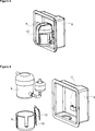
- Figure 3 – is the perspective view of a container, a compressor and a bracket.
- Figure 4 – is the exploded view of a container, a carrier, a compressor and a bracket.
- Figure 5 — is the partial perspective view of the outer wall when the cover is mounted thereon.
- the cooling device (1) comprises a body (2), an outer wall (3) closing the rear side of the body (2), an inner wall (4) situated opposite to the outer wall (3) and facing the interior of the body (2), an insulation member (5) situated between the outer wall (3) and the inner wall (4) and a compressor (6) that provides the realization of the refrigeration cycle.
- the cooling device (1) of the present invention comprises the compressor (6) that is at least partially embedded into the insulation member (5).
- the compressor (6) being embedded into the insulation member (5), an additional volume is not needed in order to place the compressor (6) into the cooling device (1) and thus the inner volume of the cooling device (1) is used efficiently.
- sounds originating from the operation of the compressor (6) are provided to be absorbed ( Figure 1, Figure 2).
- the cooling device (1) comprises at least one recess (7) arranged at the part of the insulation member (5), facing the outer wall (3).
- the depth of the recess (7) is at least partially smaller than the depth of the insulation member (5).
- the insulation member (5) is situated between the recess (7) and the inner wall (4).
- the cooling device (1) comprises at least one container (8) placed into the recess (7) and wherein the compressor (6) is placed.
- the container (8) is at least partially shaped as a receptacle.
- the inner surface of the recess (7) almost completely contacts the outer surface of the container (8) and the container (8) is tightly seated into the recess (7).
- the container (8) is fixed into the recess (7) by means of methods such as adhesion, screwing, etc. ( Figure 3, Figure 4).
- the cooling device (1) comprises at least one carrier (9) placed into the container (8) and wherein the compressor (6) is placed.
- the compressor (6) is tightly seated into the carrier (9).
- the carrier (9) By means of the carrier (9), the compressor (6) is prevented from sliding sideways while operating ( Figure 4).
- the cooling device (1) comprises at least one protrusion (10) situated on the carrier (9) and at least one channel (11) arranged at the inner side of the container (8) and wherein the protrusion (10) is seated.
- the protrusion (10) is at least partially shaped as a claw. While the carrier (9) is being placed into the container (8), the protrusion (10) is inserted into the channel (11), thus the carrier (9) is fixed to the container (8) ( Figure 4).
- the cooling device (1) comprises at least one bracket (12) that at least partially contacts the compressor (6) and that absorbs the vibrations during the operation of the compressor (6).
- the amount of vibration transmitted to the body (2) during the operation of the compressor (6) is at least partially decreased ( Figure 3, Figure 4).
- the bracket (12) is produced from a vibration-absorbing material.
- the absorbing ability of the bracket (12) is improved.
- the bracket (12) is attached to the carrier (9) and at least partially surrounds the compressor (6).
- the bracket (12) is attached to the carrier (9) from at least one of its two ends. While the compressor (6) is being placed into the carrier (9), the top of the carrier (9) is open. After the compressor (6) is placed into the carrier (9), the bracket (12) is moved to be fitted over the compressor (6).
- the bracket (12) that is at least partially U-shaped surrounds the upper side of the compressor (6).
- the bracket (12) serves as a headpiece that limits the upwards/downwards movement of the compressor (6) while operating.
- the cooling device (1) comprises at least one cover (13) that is mounted to the outer wall (3) and that covers the front of the part of the compressor (6) that remains outside the outer wall (3).
- the cover (13) is fixed to the outer wall (3) by means of fixing members such as screw, etc.
- the cover (13) is fixed to the outer wall (3), the part of the compressor (6) facing the outer wall (3) is covered by the cover (13).
- sounds originating from the operation of the compressor (6) are at least partially absorbed by means of the cover (13) ( Figure 5).
- the cooling device (1) comprises at least one hole (14) that is arranged on the cover (13) and that allows air entry/exit.
- the holes (14) By means of the holes (14), the heat emanating from the compressor (6) is discharged outside.
- pipes that provide refrigerant entry/exit into/from the compressor (6) are passed through the hole (14) ( Figure 5).
- the entire compressor (6) is placed into the insulation member (5).
- the thickness of the compressor (6) is smaller than the thickness of the insulation member (5).
- the compressor (6) is prevented from leaving the insulation member (5) and occupying additional volume.
- a cooling device (1) By means of the present invention, a cooling device (1), the inner volume of which is efficiently used is realized. Being embedded into the insulation member (5), the compressor (6) is prevented from occupying an additional space in the cooling device (1). Moreover, convenience is provided in the production of the cooling device (1) body (2). With the compressor (6) being situated in the insulation member (5), sounds originating from the operation of the compressor (6) are absorbed.
Landscapes
- Engineering & Computer Science (AREA)
- Chemical & Material Sciences (AREA)
- Combustion & Propulsion (AREA)
- Physics & Mathematics (AREA)
- Mechanical Engineering (AREA)
- Thermal Sciences (AREA)
- General Engineering & Computer Science (AREA)
- Compressor (AREA)
- Structures Of Non-Positive Displacement Pumps (AREA)
Abstract
The present invention relates to a cooling device (1) comprising a body (2), an outer wall (3) closing the rear side of the body (2), an inner wall (4) situated opposite to the outer wall (3) and facing the interior of the body (2), an insulation member (5) situated between the outer wall (3) and the inner wall (4) and a compressor (6) that provides the realization of the refrigeration cycle.
Description
The present invention relates to a cooling device, the inner volume of which is efficiently used.
In cooling devices, compressors used in order to realize the refrigeration cycle are generally placed into a compartment that is situated below or over the refrigeration cabinet. This compartment wherein the compressor is situated causes the inner volume of the cooling device to be narrowed.
In the state of the art European Patent Document No. EP1562012, an insulating wall that extends along the outer wall of the refrigerator and that provides insulation, and a case that is attached to the insulating wall, that is situated at the lower side of the refrigerator cabinet and wherein refrigeration components such as compressor, fan, etc. are placed, are disclosed.
In the state of the art Japanese Patent Document No. JP2010007910, a cooling device is disclosed, having an insulating case wherein the compressor is placed.
The aim of the present invention is the realization of a cooling device, the inner volume of which is efficiently used.
The cooling device of the present invention realized in order to attain the aim of the present invention, explicated in the claims comprises an insulation member situated between the inner wall and the outer wall, and a compressor situated in the insulation member. An additional volume is not needed in order to place the compressor into the cooling device. Thus, the efficient use of the inner volume is provided.
In an embodiment of the present invention, the cooling device comprises at least one recess arranged at the part of the insulation member, facing the outer wall. The recess is formed on the insulation member during or after the production by means of methods such as hollowing out, etc.
In an embodiment of the present invention, the cooling device comprises at least one container seated into the recess and wherein the compressor is mounted. The container is fixed to the recess by means of methods such as snap-fitting, etc.
In an embodiment of the present invention, the cooling device comprises at least one carrier seated into the container and wherein the compressor is mounted. By means of the carrier, the compressor is prevented from moving sideways during operation.
In an embodiment of the present invention, the cooling device comprises at least one protrusion situated on the carrier and at least one channel situated at the inner side of the container. While the carrier is being seated into the container, the protrusion enters the channel and provides the carrier to be fixed to the container.
In an embodiment of the present invention, the cooling device comprises at least one bracket that absorbs vibrations occurring during the operation of the compressor by contacting the compressor.
In an embodiment of the present invention, the bracket is produced from vibration-absorbing material. Thus, the absorbing ability of the bracket is improved.
In an embodiment of the present invention, the bracket is attached to the carrier so as to at least partially surround the compressor. The bracket surrounds the part of the compressor that remains outside the carrier. The compressor stays between the bracket and the carrier, and the bracket limits the upwards/downwards or forwards/backwards movements of the compressor. Thus, the bracket is provided to be kept in the carrier in a rigid manner.
In an embodiment of the present invention, the cooling device comprises at least one cover that is mounted to the outer wall and that covers the front of the part of the compressor that remains outside the outer wall. That the front of the compressor placed into the outer wall is covered by means of the cover enables the compressor to be kept in an enclosed volume.
In an embodiment of the present invention, the cooling device comprises at least one hole arranged on the cover. By means of the holes, air entry/exit is provided. Thus, the heat emanating from the compressor is discharged. Moreover, pipes that provide refrigerant entry/exit into/from the compressor are passed through the hole.
In an embodiment of the present invention, the entire compressor is placed into the insulation member. Thus, the compressor is prevented from occupying an additional volume.
In a derivative of this embodiment, the thickness of the compressor is smaller than the depth of the insulation member.
By means of the present invention, a cooling device is realized, having a compressor that enables the inner volume thereof to be used efficiently by being embedded into the insulation member.
The cooling device realized in order to attain the aim of the present invention is illustrated in the attached figures, where:
Figure 1 – is the perspective view of a cooling device.
Figure 2 – is the sideways partial cross-sectional view of the cooling device.
Figure 3 – is the perspective view of a container, a compressor and a bracket.
Figure 4 – is the exploded view of a container, a carrier, a compressor and a bracket.
Figure 5 – is the partial perspective view of the outer wall when the cover is mounted thereon.
The elements illustrated in the figures are numbered as follows:
- Cooling device
- Body
- Outer wall
- Inner wall
- Insulation member
- Compressor
- Recess
- Container
- Carrier
- Protrusion
- Channel
- Bracket
- Cover
- Hole
The cooling device (1) comprises a body (2), an outer wall (3) closing the rear side of the body (2), an inner wall (4) situated opposite to the outer wall (3) and facing the interior of the body (2), an insulation member (5) situated between the outer wall (3) and the inner wall (4) and a compressor (6) that provides the realization of the refrigeration cycle.
The cooling device (1) of the present invention comprises the compressor (6) that is at least partially embedded into the insulation member (5). With the compressor (6) being embedded into the insulation member (5), an additional volume is not needed in order to place the compressor (6) into the cooling device (1) and thus the inner volume of the cooling device (1) is used efficiently. Moreover, with the compressor (6) being situated in the insulation member (5), sounds originating from the operation of the compressor (6) are provided to be absorbed (Figure 1, Figure 2).
In an embodiment of the present invention, the cooling device (1) comprises at least one recess (7) arranged at the part of the insulation member (5), facing the outer wall (3). The depth of the recess (7) is at least partially smaller than the depth of the insulation member (5). The insulation member (5) is situated between the recess (7) and the inner wall (4). Thus, the insulation efficiency of the cooling device (1) is maintained (Figure 1, Figure 2).
In an embodiment of the present invention, the cooling device (1) comprises at least one container (8) placed into the recess (7) and wherein the compressor (6) is placed. The container (8) is at least partially shaped as a receptacle. The inner surface of the recess (7) almost completely contacts the outer surface of the container (8) and the container (8) is tightly seated into the recess (7). The container (8) is fixed into the recess (7) by means of methods such as adhesion, screwing, etc. (Figure 3, Figure 4).
In an embodiment of the present invention, the cooling device (1) comprises at least one carrier (9) placed into the container (8) and wherein the compressor (6) is placed. The compressor (6) is tightly seated into the carrier (9). By means of the carrier (9), the compressor (6) is prevented from sliding sideways while operating (Figure 4).
In an embodiment of the present invention, the cooling device (1) comprises at least one protrusion (10) situated on the carrier (9) and at least one channel (11) arranged at the inner side of the container (8) and wherein the protrusion (10) is seated. The protrusion (10) is at least partially shaped as a claw. While the carrier (9) is being placed into the container (8), the protrusion (10) is inserted into the channel (11), thus the carrier (9) is fixed to the container (8) (Figure 4).
In an embodiment of the present invention, the cooling device (1) comprises at least one bracket (12) that at least partially contacts the compressor (6) and that absorbs the vibrations during the operation of the compressor (6). Thus, the amount of vibration transmitted to the body (2) during the operation of the compressor (6) is at least partially decreased (Figure 3, Figure 4).
In an embodiment of the present invention, the bracket (12) is produced from a vibration-absorbing material. Thus, the absorbing ability of the bracket (12) is improved.
In an embodiment of the present invention, the bracket (12) is attached to the carrier (9) and at least partially surrounds the compressor (6). The bracket (12) is attached to the carrier (9) from at least one of its two ends. While the compressor (6) is being placed into the carrier (9), the top of the carrier (9) is open. After the compressor (6) is placed into the carrier (9), the bracket (12) is moved to be fitted over the compressor (6). The bracket (12) that is at least partially U-shaped surrounds the upper side of the compressor (6). Thus, the bracket (12) serves as a headpiece that limits the upwards/downwards movement of the compressor (6) while operating.
In an embodiment of the present invention, the cooling device (1) comprises at least one cover (13) that is mounted to the outer wall (3) and that covers the front of the part of the compressor (6) that remains outside the outer wall (3). The cover (13) is fixed to the outer wall (3) by means of fixing members such as screw, etc. When the cover (13) is fixed to the outer wall (3), the part of the compressor (6) facing the outer wall (3) is covered by the cover (13). Moreover, sounds originating from the operation of the compressor (6) are at least partially absorbed by means of the cover (13) (Figure 5).
In an embodiment of the present invention, the cooling device (1) comprises at least one hole (14) that is arranged on the cover (13) and that allows air entry/exit. By means of the holes (14), the heat emanating from the compressor (6) is discharged outside. Moreover, pipes that provide refrigerant entry/exit into/from the compressor (6) are passed through the hole (14) (Figure 5).
In an embodiment of the present invention, the entire compressor (6) is placed into the insulation member (5).
In a derivative of this embodiment, the thickness of the compressor (6) is smaller than the thickness of the insulation member (5). Thus, the compressor (6) is prevented from leaving the insulation member (5) and occupying additional volume.
By means of the present invention, a cooling device (1), the inner volume of which is efficiently used is realized. Being embedded into the insulation member (5), the compressor (6) is prevented from occupying an additional space in the cooling device (1). Moreover, convenience is provided in the production of the cooling device (1) body (2). With the compressor (6) being situated in the insulation member (5), sounds originating from the operation of the compressor (6) are absorbed.
It is to be understood that the present invention is not limited to the embodiments disclosed above and a person skilled in the art can easily introduce different embodiments. These should be considered within the scope of the protection postulated by the claims of the present invention.
Claims (12)
- A cooling device (1) comprising a body (2), an outer wall (3) closing the rear side of the body (2), an inner wall (4) situated opposite to the outer wall (3) and facing the interior of the body (2), an insulation member (5) situated between the outer wall (3) and the inner wall (4) and a compressor (6) that provides the realization of the refrigeration cycle, characterized by the compressor (6) that is at least partially embedded into the insulation member (5).
- The cooling device (1) as in Claim 1, characterized by at least one recess (7) that is arranged on the part of the insulation member (5) facing the outer wall (3).
- The cooling device (1) as in Claim 2, characterized by at least one container (8) that is placed into the recess (7) and wherein the compressor (6) is placed.
- The cooling device (1) as in Claim 3, characterized by at least one carrier (9) that is placed into the container (8) and wherein the compressor (6) is placed.
- The cooling device (1) as in Claim 4, characterized by at least one protrusion (10) situated on the carrier (9) and at least one channel (11) arranged at the inner side of the container (8) and wherein the protrusion (10) is seated.
- The cooling device (1) as in any one of the above claims, characterized by at least one bracket (12) that at least partially contacts the compressor (6) and that absorbs the vibrations during the operation of the compressor (6).
- The cooling device (1) as in Claim 6, characterized by the bracket (12) that is produced from a vibration-absorbing material.
- The cooling device (1) as in Claim 6 or 7, characterized by the bracket (12) that is attached to the carrier (9) and that at least partially surrounds the compressor (6).
- The cooling device (1) as in any one of the above claims, characterized by at least one cover (13) that is mounted to the outer wall (3) and that covers the front of the part of the compressor (6) that remains outside the outer wall (3).
- The cooling device (1) as in Claim 9, characterized by at least one hole (14) that is arranged on the cover (13) and that allows air entry/exit.
- The cooling device (1) as in any one of the claims 1 to 8, characterized by the compressor (6) that is entirely embedded into the insulation member (5).
- The cooling device (1) as in Claim 11, characterized by the compressor (6), the thickness of which is smaller than the thickness of the insulation member (5).
Applications Claiming Priority (2)
| Application Number | Priority Date | Filing Date | Title |
|---|---|---|---|
| TRA2012/13488 | 2012-11-21 | ||
| TR2012/13488A TR201213488A1 (en) | 2012-11-21 | 2012-11-21 | Internal volume of the used coolant. |
Publications (1)
| Publication Number | Publication Date |
|---|---|
| WO2014079669A1 true WO2014079669A1 (en) | 2014-05-30 |
Family
ID=49578267
Family Applications (1)
| Application Number | Title | Priority Date | Filing Date |
|---|---|---|---|
| PCT/EP2013/072707 Ceased WO2014079669A1 (en) | 2012-11-21 | 2013-10-30 | Cooling device with efficiently used inner volume |
Country Status (2)
| Country | Link |
|---|---|
| TR (1) | TR201213488A1 (en) |
| WO (1) | WO2014079669A1 (en) |
Cited By (1)
| Publication number | Priority date | Publication date | Assignee | Title |
|---|---|---|---|---|
| JP2024062082A (en) * | 2022-10-24 | 2024-05-09 | 東芝ライフスタイル株式会社 | refrigerator |
Citations (3)
| Publication number | Priority date | Publication date | Assignee | Title |
|---|---|---|---|---|
| JPS59129080U (en) * | 1983-02-09 | 1984-08-30 | 株式会社東芝 | refrigerator |
| JP2007003182A (en) * | 2006-05-22 | 2007-01-11 | Matsushita Electric Ind Co Ltd | refrigerator |
| DE102008043803A1 (en) * | 2008-11-18 | 2010-05-20 | BSH Bosch und Siemens Hausgeräte GmbH | Domestic refrigerator with a machine room |
-
2012
- 2012-11-21 TR TR2012/13488A patent/TR201213488A1/en unknown
-
2013
- 2013-10-30 WO PCT/EP2013/072707 patent/WO2014079669A1/en not_active Ceased
Patent Citations (3)
| Publication number | Priority date | Publication date | Assignee | Title |
|---|---|---|---|---|
| JPS59129080U (en) * | 1983-02-09 | 1984-08-30 | 株式会社東芝 | refrigerator |
| JP2007003182A (en) * | 2006-05-22 | 2007-01-11 | Matsushita Electric Ind Co Ltd | refrigerator |
| DE102008043803A1 (en) * | 2008-11-18 | 2010-05-20 | BSH Bosch und Siemens Hausgeräte GmbH | Domestic refrigerator with a machine room |
Cited By (2)
| Publication number | Priority date | Publication date | Assignee | Title |
|---|---|---|---|---|
| JP2024062082A (en) * | 2022-10-24 | 2024-05-09 | 東芝ライフスタイル株式会社 | refrigerator |
| JP7894789B2 (en) | 2022-10-24 | 2026-07-24 | 美的集団股▲フン▼有限公司 | refrigerator |
Also Published As
| Publication number | Publication date |
|---|---|
| TR201213488A1 (en) | 2014-06-23 |
Similar Documents
| Publication | Publication Date | Title |
|---|---|---|
| KR102820003B1 (en) | Vacuum adiabatic body, refrigerating or warming apparatus, and vehicle | |
| RU2006116417A (en) | CASE OF THE REFRIGERATING UNIT | |
| TWI449874B (en) | Refrigerator | |
| EP3330647A1 (en) | Home appliance device and method for assembling a home appliance device | |
| KR20140075301A (en) | Refrigerator | |
| RU2011140425A (en) | HOUSEHOLD REFRIGERATING UNIT AND COOLING DEVICE FOR DOMESTIC REFRIGERATING UNIT | |
| WO2011081500A3 (en) | Refrigerator | |
| JP6448984B2 (en) | refrigerator | |
| WO2012010455A3 (en) | Refrigerator, in particular a household refrigeration appliance | |
| JP2018004183A (en) | Refrigerator | |
| US20120118000A1 (en) | Refrigerator | |
| JP6723500B2 (en) | Mounting structure and refrigerator | |
| AU2016389530A1 (en) | Refrigerator | |
| US20150292821A1 (en) | Cooling device having an elastic fixing member and a valve holder group | |
| KR102643919B1 (en) | refrigerator with compressor | |
| WO2015113981A1 (en) | A cooling device comprising an evaporation tray | |
| JP2022015025A (en) | refrigerator | |
| KR101598627B1 (en) | Refrigerator | |
| WO2013000968A2 (en) | A refrigerator comprising a machine room | |
| WO2014072131A1 (en) | Compressor comprising cylinder head | |
| JPWO2020070770A1 (en) | refrigerator | |
| JP6688951B2 (en) | refrigerator | |
| US20180156519A1 (en) | Home Appliance Device | |
| JP4244862B2 (en) | refrigerator | |
| KR101059242B1 (en) | Switch structure of the dispenser of the refrigerator |
Legal Events
| Date | Code | Title | Description |
|---|---|---|---|
| 121 | Ep: the epo has been informed by wipo that ep was designated in this application |
Ref document number: 13789512 Country of ref document: EP Kind code of ref document: A1 |
|
| NENP | Non-entry into the national phase |
Ref country code: DE |
|
| 122 | Ep: pct application non-entry in european phase |
Ref document number: 13789512 Country of ref document: EP Kind code of ref document: A1 |