WO2014070726A1 - Apparatus and method for deep transient resistivity measurement - Google Patents
Apparatus and method for deep transient resistivity measurement Download PDFInfo
- Publication number
- WO2014070726A1 WO2014070726A1 PCT/US2013/067245 US2013067245W WO2014070726A1 WO 2014070726 A1 WO2014070726 A1 WO 2014070726A1 US 2013067245 W US2013067245 W US 2013067245W WO 2014070726 A1 WO2014070726 A1 WO 2014070726A1
- Authority
- WO
- WIPO (PCT)
- Prior art keywords
- bucking
- coefficient
- formation
- initial
- signal
- Prior art date
- Legal status (The legal status is an assumption and is not a legal conclusion. Google has not performed a legal analysis and makes no representation as to the accuracy of the status listed.)
- Ceased
Links
Classifications
-
- G—PHYSICS
- G01—MEASURING; TESTING
- G01V—GEOPHYSICS; GRAVITATIONAL MEASUREMENTS; DETECTING MASSES OR OBJECTS; TAGS
- G01V3/00—Electric or magnetic prospecting or detecting; Measuring magnetic field characteristics of the earth, e.g. declination, deviation
- G01V3/38—Processing data, e.g. for analysis, for interpretation, for correction
-
- E—FIXED CONSTRUCTIONS
- E21—EARTH OR ROCK DRILLING; MINING
- E21B—EARTH OR ROCK DRILLING; OBTAINING OIL, GAS, WATER, SOLUBLE OR MELTABLE MATERIALS OR A SLURRY OF MINERALS FROM WELLS
- E21B47/00—Survey of boreholes or wells
-
- G—PHYSICS
- G01—MEASURING; TESTING
- G01V—GEOPHYSICS; GRAVITATIONAL MEASUREMENTS; DETECTING MASSES OR OBJECTS; TAGS
- G01V3/00—Electric or magnetic prospecting or detecting; Measuring magnetic field characteristics of the earth, e.g. declination, deviation
- G01V3/18—Electric or magnetic prospecting or detecting; Measuring magnetic field characteristics of the earth, e.g. declination, deviation specially adapted for well-logging
- G01V3/26—Electric or magnetic prospecting or detecting; Measuring magnetic field characteristics of the earth, e.g. declination, deviation specially adapted for well-logging operating with magnetic or electric fields produced or modified either by the surrounding earth formation or by the detecting device
-
- G—PHYSICS
- G06—COMPUTING OR CALCULATING; COUNTING
- G06F—ELECTRIC DIGITAL DATA PROCESSING
- G06F17/00—Digital computing or data processing equipment or methods, specially adapted for specific functions
- G06F17/40—Data acquisition and logging
-
- G—PHYSICS
- G16—INFORMATION AND COMMUNICATION TECHNOLOGY [ICT] SPECIALLY ADAPTED FOR SPECIFIC APPLICATION FIELDS
- G16Z—INFORMATION AND COMMUNICATION TECHNOLOGY [ICT] SPECIALLY ADAPTED FOR SPECIFIC APPLICATION FIELDS, NOT OTHERWISE PROVIDED FOR
- G16Z99/00—Subject matter not provided for in other main groups of this subclass
Definitions
- Geologic formations below the surface of the earth may contain reservoirs of oil and gas, which are retrieved by drilling one or more boreholes into the subsurface of the earth.
- the boreholes are also used to measure various properties of the boreholes and the surrounding subsurface formations.
- Exemplary techniques include using ferrite and copper shielding, using reference signal for calibration purposes and using asymptotic behavior of the conductive collar time response to filter out the collar signal.
- the conductive collar signal is typically more than two orders of magnitude greater than the formation signal even if ferrite and copper shields are used. Then the accuracy of bucking and filtering may not be sufficient to facilitate measurements.
- a method of processing electromagnetic signal data includes: receiving transient electromagnetic (TEM) signal data representing electromagnetic (EM) signals detected by at least two receivers in a downhole tool disposed in an earth formation in response to inducing a pulsed current in the earth formation, the downhole tool including at least one conductive component; estimating an initial bucking coefficient based on relative positions of the at least two receivers; combining the TEM signal data using the initial bucking coefficient to estimate an initial formation signal; selecting a plurality of bucking coefficient values based on the initial bucking coefficient and estimating a plurality of formation signals, each formation signal corresponding to one of the plurality of bucking coefficients; and selecting an optimal bucking coefficient from one of the initial bucking coefficient and the plurality of bucking coefficients based on the plurality of formation signals, the optimal bucking coefficient providing suppression of parasitic signals due to the at least one conductive component.
- TEM transient electromagnetic
- EM electromagnetic
- An apparatus for processing electromagnetic signal data includes: a downhole tool configured to be disposed in a borehole in an earth formation, the downhole tool including a conductive carrier, a transmitter, a first receiver disposed at a first axial distance Li from the transmitter, and a second receiver disposed at a second axial distance L 2 from the transmitter that is less than the first axial distance; and a processor configured to receive transient electromagnetic (TEM) signal data representing a first EM signal Si(t) detected by the first receiver and a second EM signal detected by the second receiver in response to inducing a pulsed current in the earth formation.
- TEM transient electromagnetic
- the processor is configured to perform: estimating an initial bucking coefficient based on at least the first axial distance Li and the second axial distance L 2 ; combining the first EM signal Si(t) and the second EM signal using the initial bucking coefficient to estimate an initial formation signal; selecting a plurality of bucking coefficient values based on the initial bucking coefficient and estimating a plurality of formation signals, each formation signal corresponding to one of the plurality of bucking coefficients; and selecting an optimal bucking coefficient from one of the initial bucking coefficient and the plurality of bucking coefficients based on the plurality of formation signals, the optimal bucking coefficient providing suppression of parasitic signals due to the at least one conductive component.
- a non-transitory computer readable medium includes computer-executable instructions for processing electromagnetic signal data by implementing a method
- TEM transient electromagnetic
- EM signals detected by at least two receivers in a downhole tool disposed in an earth formation in response to inducing a pulsed current in the earth formation, the downhole tool including at least one conductive component; estimating an initial bucking coefficient based on relative positions of the at least two receivers; combining the TEM data using the initial bucking coefficient to estimate an initial formation signal; selecting a plurality of bucking coefficient values based on the initial bucking coefficient and estimating a plurality of formation signals, each formation signal corresponding to one of the plurality of bucking coefficients; and selecting an optimal bucking coefficient from one of the initial bucking coefficient and the plurality of bucking coefficients based on the plurality of formation signals, the optimal bucking coefficient providing suppression of parasitic signals due to the at least one conductive component.
- EM electromagnetic
- FIG. 1 depicts an exemplary embodiment of a drilling, formation evaluation and/or production system
- FIG. 2 depicts an exemplary embodiment of a downhole tool
- FIG. 3 depicts a structure representing an exemplary configuration of the downhole tool of FIG. 2 in an earth formation
- FIG. 4 depicts exemplary transient electromagnetic responses obtained in the presence of a typical conductive pipe
- FIG. 5 is a flow chart providing an exemplary method of processing electromagnetic signal data and/or measuring formation properties
- FIG. 6 depicts exemplary electromagnetic receiver signals
- FIG. 7 depicts exemplary formation signals derived according to the method of FIG. 5 for a homogeneous formation
- FIG. 8 depicts exemplary formation signals derived according to the method of FIG. 5 for a homogeneous formation
- FIG. 9 depicts exemplary formation signals derived according to the method of FIG. 5 for a homogeneous formation
- FIG. 10 depicts an electromagnetic measurement tool disposed in an exemplary formation
- FIG. 11 depicts exemplary formation signals derived according to the method of FIG. 5 for the formation depicted in FIG. 10.
- Apparatuses and methods are provided for reducing and/or eliminating parasitic signal data due to downhole components (e.g., conductive drill collars, borehole strings or tool components) from electromagnetic (EM) measurement data.
- the apparatuses and methods described herein are utilized with transient EM operations, such as ultra-deep resistivity measurement while drilling.
- An exemplary method is based on acquiring EM signals from at least a first and second EM receiver that are axially spaced downhole relative to an EM transmitter.
- a first EM signal is generated from the first receiver and a second EM signal is generated from the second receiver located closer to the transmitter.
- the second receiver is combined with a coefficient to generate a transformed signal, which can be subtracted from the first EM signal to generate a corrected EM signal that is free (or at least substantially free) of the parasitic signal.
- the first and second receivers are utilized as a bucking system for effective reduction or elimination of effects of conductive components (e.g., drill pipes) on signals in transient EM measurements (e.g., Pulse Induction LWD).
- One receiver such as the first receiver, serves as the main measurement receiver, while another receiver, such as the second receiver, is used to compensate for undesirable effects, e.g., a drill pipe parasitic signal.
- a correctable bucking coefficient is derived from the raw transient measurements taken by electromagnetic receivers. Bucking is performed by measuring signals by each receiver and then combining the measured signals using the correctable bucking coefficient to derive a formation signal that is substantially unaffected by the conductive component.
- an exemplary embodiment of a well drilling, logging and/or production system 10 includes a borehole string 12 that is shown disposed in a wellbore or borehole 14 that penetrates at least one earth formation 16 during a drilling or other downhole operation.
- borehole or “wellbore” refers to a single hole that makes up all or part of a drilled well.
- formations refer to the various features and materials that may be encountered in a subsurface environment and surround the borehole.
- a surface structure 18 includes various components such as a wellhead, derrick and/or rotary table or supporting the borehole string, lowering string sections or other downhole components.
- the borehole string 12 is a drillstring including one or more drill pipe sections that extend downward into the borehole 14, and is connected to a drilling assembly 20.
- system 10 includes any number of downhole tools 24 for various processes including formation drilling, geosteering, and formation evaluation (FE) for measuring versus depth and/or time one or more physical quantities in or around a borehole.
- the tool 24 may be included in or embodied as a bottomhole assembly (BHA) 22, drillstring component or other suitable carrier.
- BHA bottomhole assembly
- a “carrier” as described herein means any device, device component, combination of devices, media and/or member that may be used to convey, house, support or otherwise facilitate the use of another device, device component, combination of devices, media and/or member.
- Exemplary non-limiting carriers include drill strings of the coiled tubing type, of the jointed pipe type and any combination or portion thereof.
- Other carrier examples include casing pipes, wirelines, wireline sondes, slickline sondes, drop shots, downhole subs, bottom-hole assemblies, and drill strings.
- the tool 24, the BHA 22 or other portions of the borehole string 12 includes sensor devices configured to measure various parameters of the formation and/or borehole.
- the sensor devices include one or more transmitters and receivers configured to transmit and receive electromagnetic signals for measurement of formation properties such as composition, resistivity and permeability.
- An exemplary measurement technique is a transient EM technique.
- the tool 24, BHA 22 and/or sensor devices include and/or are configured to communicate with a processor to receive, measure and/or estimate directional and other characteristics of the downhole components, borehole and/or the formation.
- the tool 24 is equipped with transmission equipment to
- Such transmission equipment may take any desired form, and different transmission media and connections may be used. Examples of connections include wired, fiber optic, acoustic, wireless connections and mud pulse telemetry.
- the processor may be configured to receive data from the tool 24 and/or process the data to generate formation parameter information.
- the surface processing unit 28 is configured as a surface drilling control unit which controls various drilling parameters such as rotary speed, weight-on-bit, drilling fluid flow parameters and others.
- the tool 24 is configured as a downhole logging tool.
- logging refers to the taking of formation property measurements.
- FIG. 2 illustrates an embodiment of the downhole tool 24.
- the downhole tool 24 is disposed in a carrier such as a housing 30.
- the housing is incorporated as or in a downhole component such as a borehole string section, a drill pipe or a drill collar.
- the housing 30 and/or other component are typically made from a conducting material such as steel.
- the tool 24 includes a resistivity measurement assembly 32 incorporating at least one electromagnetic (EM) source and multiple EM receivers.
- An EM transmitter 34 e.g., a transmitter antenna or coil
- An electric source 40 is configured to apply electric current to the transmitter 34.
- the measurement assembly 32 is configured to perform an inductive transient EM measurement operation.
- the source 40 applies transient pulses of current to the transmitter 34, which induces current in the formation 16.
- the current generates a magnetic field that is detected by the receivers 36 and 38.
- the tool 24 utilizes electromagnetic measurements to determine the electrical conductivity of formations surrounding the borehole.
- Various types of tools may be employed to measure formations at various "depths of investigations" or DOI, which correspond to distances from the tool and/or borehole in a direction perpendicular to an axis of the tool and/or borehole (e.g., the Z axis of FIG. 2), referred to herein as "radial distances.”
- Transient EM methods are particularly useful for ultra-deep investigations (e.g., radial distances of 10s to hundreds of meters from the tool and/or borehole).
- voltage or current pulses that are excited in a transmitter initiate the propagation of an electromagnetic signal in the earth formation.
- the transient electromagnetic field is sensitive only to remote formation zones and does not depend on the resistivity distribution in the vicinity of the transmitter.
- the transmitter and the receivers are disposed axially relative to one another.
- An "axial" location refers to a location along the Z axis that extends along a length of the tool 24 and/or borehole 14.
- the first receiver 36 is positioned at a selected axial distance LI from the transmitter 34
- the second receiver 38 is positioned at a shorter axial distance L2 from the transmitter.
- the first and second distances are selected to have a specific ratio, e.g., LI is twice that of L2.
- the receivers 36 and 38 are identical or at least substantially identical, such that they would measure the same signal if the receivers are disposed at the same axial and radial location.
- the receivers 36 and 38 each have the same (or at least substantially the same) configuration parameters. Such parameters include the number and diameter of coil windings, the coil material, the effective area, the magnetic field to voltage conversion factor and/or voltage gain.
- FIG. 3 shows an exemplary structure representing a configuration of the tool 24 with the formation 16,
- the structure includes a first zone 42 substantially defined by a metai drill collar, pipe or other conductive carrier with conductivity ⁇ , a transition layer 44 having a conductivity ⁇ ?, and a remote formation layer 46 having a conductivity ⁇ ? .
- the magnetic permeab lity of the entire space is ⁇ .
- the boundary 48 separating the metal carrier from the transition layer and the boundary 50 separating the regions of transition layer and remote formation share a common Z-axis, As measured from the Z-axis, the radius of boundary 48 is labeled as r mtl , and the radius of boundary 50 is labeled as 3 ⁇ 4.
- An electromagnetic field is exci ted by the transmi tter c urren t loop 34 of radius, 3 ⁇ 4, and is measured by receivers 36 and 38 of radius r ⁇ .
- FIG. 4 shows exemplary transient responses obtained in the presence of a typical conductive pipe.
- Curves 51, 52 and 53 indicate responses at radial distances (perpendicular to the Z axis) of 1, 2, and 4 meters respectively to a remote boundary (e.g., boundary 204).
- Response curve 54 represents the response to a remote boundary at an infinite distance.
- Response curve 54 is nearly indistinguishable from and overlaps response curves at a distance of 6, 8 and 10 meters.
- FIG. 4 illustrates the fact that at late times corresponding to deep investigation, the conductive pipe signal typically dominates the tra sie t response of the earth's formations by at least an order of magnitude.
- FIG. 5 illustrates a method 60 for processing electromagnetic (EM) signal data and measuring parameters of an earth formation using electromagnetic signal measurements.
- EM electromagnetic
- the method includes processing and/or analyzing received signals to reduce and/or eliminate the signal corresponding to conductive downhole components such as drill collars or drill pipes from EM data, such as transient EM (TE ) data.
- EM data such as transient EM (TE ) data.
- the method 60 includes one or more of stages 61-66 described herein. The method may be performed continuously or
- the method is described herein in conjunction with the tool 24, although the method may be performed in conjunction with any number and configuration of processors, sensors and tools.
- the method may be performed by one or more processors or other devices capable of receiving and processing measurement data.
- the method includes the execution of all of stages 61-66 in the order described. However, certain stages 61-66 may be omitted, stages may be added, or the order of the stages changed.
- the tool 24 is lowered in the borehole.
- the tool 24 may be lowered, for example, during a drilling operation, LWD operation or via a wireline.
- each receiver signal can encompass one or multiple signals over one or more time intervals.
- the first receiver 36 (also referred to as receiver Rj) is considered the main measurement receiver, for which a time domain signal Si(t) is measured over a selected time interval.
- the second receiver 38 (also referred to as receiver R 2 ) is used to measure a time domain signal over the selected time interval, and is provided to compensate for undesirable parasitic signals.
- the combination is a linear combination.
- a transformation is applied to the second receiver signal to generate a transformed signal.
- the transformed signal is then subtracted from the first receiver signal Si(t) to generate a corrected signal that is entirely or at least substantially entirely free of the portion of the first signal due to the conductive drill pipe or other downhole component.
- the second receiver signal is transformed by multiplying the receiver signal by the bucking coefficient.
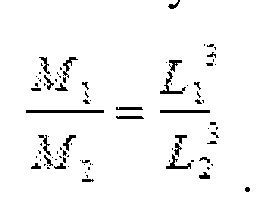
- the bucking coefficient may be a constant based on, e.g., a ratio between the distance Li from Ri to the transmitter (7) and the distance L 2 from R 2 to the transmitter T.
- An exemplary ratio is ( - ) 3 ( Lj f.
- an initial bucking coefficient k is calculated based on, e.g., a ratio between Li and L 2 .
- the initial bucking coefficient k is calculated based on the following equation:
- An initial signal ASo(t) is calculated by combining the two signals Si(t) and using the initial bucking coefficient.
- This signal ASo(t) is referred to an initial formation signal, which is an initial estimation of a corrected formation signal for which the influence of a drill string or other conductive components (e.g., a parasitic signal) is reduced or eliminated.
- the initial formation signal ASo(t) is calculated according to the equation:
- an optimal bucking coefficient i.e., a value for the bucking coefficient that most substantially eliminates the parasitic signal, is calculated by estimating a plurality of signals AS(t) using a plurality of bucking coefficients selected based on the value of the initial bucking coefficient.
- the plurality of bucking coefficients are selected based on the initial coefficient. For example, a number of coefficients can be selected that are within a selected percentage of the initial coefficient value.
- the criteria for selection is not limited to those described herein; the values of the coefficients, the range between k min and k max , the number of coefficients, and the interval separating the coefficients can be based around the initial coefficient using empirical data, such as knowledge of formation lithology and previously collected data.
- a scan is performed by calculating a plurality of signals AS(t) in the time interval [ t - , t m consider 1 corresponding to a range of coefficients from k - to k tract .
- each signal AS(t) is calculated for a respective bucking coefficient according to equation (13).
- the time interval is related to the measurement interval, and may be equal to the measurement interval or be some subset thereof. For example, the time interval is selected such that t . 3 ⁇ 4 0.01 ms and t ⁇ ⁇ ms .
- one of the signals (referred to as the optimal signal AS(t) opt ) is selected that corresponds to the signal that has or approaches a zero crossing (i.e., a time point at which the signal crosses or approaches a value of zero) at the latest time.
- the bucking coefficient corresponding to this optimal signal is referred to as an optimal bucking coefficient k opt , and is the coefficient that provides maximum suppression of the drill pipe parasitic signal while maximizing information content from the formation.
- the optimal coefficient k opt can be used in conjunction with subsequent electromagnetic measurements to calculate formation signals.
- the optical coefficient k opt may be recalculated at any later point, e.g., periodically after a certain number of measurements and/or in response to changing downhole conditions.
- conductivity of the formation are estimated based on formation signals calculated using the optimal coefficient. For example, inversion of calculated formation signals provides parameters of the surrounding formation including resistivity, distance to an interface in the formation (geosteering), and distance or ahead of a drill.
- FIGS. 6-1 1 illustrate examples showing the validity and usefulness of the method 60 for correction of bucking coefficient in transient MWD measurements.
- the following examples utilize a three-coil system including a transmitter and two axially spaced receivers Ri and R 2 .
- the formation includes homogeneous media with a resistivity of 1 ohm-m.
- a curve 70 shows a simulated transient signal S l (t) for the first receiver Rj and a curve 72 shows a simulated transient signal S 2 (t) for the second receiver ? -
- An initial bucking coefficient is calculated as A" _ jL 2 initial formation signal is calculated according to formula (13).
- FIG. 7 shows the initial formation signal ASo(t) as curve 74.
- a reference signal 76 is shown that corresponds to the modeled formation signal with no pipe or other conductive component included.
- the curves 74 and 76 substantially overlap within the measurement time interval and thus no further processing is needed to update the bucking coefficient, i.e., the initial bucking coefficient can be selected as the optimal coefficient.
- an optimal curve 78 is derived based on the selection criteria described above (the curve with the latest zero crossing). This optimal curve 78 slightly better coincides with the reference curve 76.
- the situation is different if the formation becomes more resistive.
- the formation includes homogeneous media with a resistivity of 10 ohm-m.
- An optimal bucking coefficient k 0.3627 leads to a formation signal 80, which is much closer to the to the reference curve 76 than the initial formation signal 82 calculated using the initial bucking coefficient.
- FIG. 9 illustrates an example in which the formation includes homogeneous media having a resistivity of 100 ohm-m.
- FIGS. 10 and 1 1 show an example of how the correction performs when a formation includes two layers and has a boundary that is placed ahead of the tool 24 (e.g., a drill bit or other component).
- the formation includes a boundary 88 between a formation layer surrounding the tool having a resistivity Roi of 50 ohm-m, and a formation layer ahead of the tool having a resistivity Ro 2 of 1 ohm-m.
- the boundary in this example is placed at 29 meters from receiver Rj.
- Curves 90 and 76 corresponding to the optimal and reference coefficients respectively, are presented in FIG.1 1.
- the apparatuses and methods described herein provide various advantages over prior art techniques.
- the apparatuses and methods allow for removing the effects of the drill collar without having to know the changes in the drill collar that occur during downhole operation.
- Such changes include environmental changes (temperature and pressure) as well as physical changes such as deformation and vibration.
- an improved adjustable bucking coefficient as described herein permits stronger suppression of undesirable signals due to conductive components while improving information content about electrical properties of a formation.
- the adjustable bucking coefficient permits an effective extraction of formation signals from electromagnetic measurements.
- some of the teachings herein are reduced to an algorithm that is stored on machine -readable media. The algorithm is implemented by a computer and provides operators with desired output.
- the systems described herein may be incorporated in a computer coupled to the tool 24.
- Exemplary components include, without limitation, at least one processor, storage, memory, input devices, output devices and the like. As these components are known to those skilled in the art, these are not depicted in any detail herein.
- the computer may be disposed in at least one of a surface processing unit and a downhole component.
- various analyses and/or analytical components may be used, including digital and/or analog systems.
- the system may have components such as a processor, storage media, memory, input, output, communications link (wired, wireless, pulsed mud, optical or other), user interfaces, software programs, signal processors (digital or analog) and other such components (such as resistors, capacitors, inductors and others) to provide for operation and analyses of the apparatus and methods disclosed herein in any of several manners well-appreciated in the art.
- teachings may be, but need not be, implemented in conjunction with a set of computer executable instructions stored on a computer readable medium, including memory (ROMs, RAMs), optical (CD-ROMs), or magnetic (disks, hard drives), or any other type that when executed causes a computer to implement the method of the present invention.
- ROMs, RAMs random access memory
- CD-ROMs compact disc-read only memory
- magnetic (disks, hard drives) any other type that when executed causes a computer to implement the method of the present invention.
- These instructions may provide for equipment operation, control, data collection and analysis and other functions deemed relevant by a system designer, owner, user or other such personnel, in addition to the functions described in this disclosure.
Landscapes
- Life Sciences & Earth Sciences (AREA)
- Engineering & Computer Science (AREA)
- Physics & Mathematics (AREA)
- Geology (AREA)
- Geophysics (AREA)
- Environmental & Geological Engineering (AREA)
- General Life Sciences & Earth Sciences (AREA)
- Mining & Mineral Resources (AREA)
- General Physics & Mathematics (AREA)
- Remote Sensing (AREA)
- Fluid Mechanics (AREA)
- Geochemistry & Mineralogy (AREA)
- General Engineering & Computer Science (AREA)
- Theoretical Computer Science (AREA)
- Data Mining & Analysis (AREA)
- Software Systems (AREA)
- Computer Hardware Design (AREA)
- Electromagnetism (AREA)
- Databases & Information Systems (AREA)
- Mathematical Physics (AREA)
- Measurement Of Resistance Or Impedance (AREA)
- Geophysics And Detection Of Objects (AREA)
- Investigating Or Analyzing Materials By The Use Of Electric Means (AREA)
Abstract
Description

Claims


Priority Applications (3)
| Application Number | Priority Date | Filing Date | Title |
|---|---|---|---|
| BR112015009382-5A BR112015009382B1 (en) | 2012-11-01 | 2013-10-29 | Method and apparatus for processing electromagnetic signal data |
| NO20150433A NO346751B1 (en) | 2012-11-01 | 2013-10-29 | Apparatus and method for deep transient resistivity measurement |
| GB1508788.5A GB2522380B (en) | 2012-11-01 | 2013-10-29 | Apparatus and method for deep transient resistivity measurement |
Applications Claiming Priority (2)
| Application Number | Priority Date | Filing Date | Title |
|---|---|---|---|
| US13/666,331 | 2012-11-01 | ||
| US13/666,331 US9310511B2 (en) | 2012-11-01 | 2012-11-01 | Apparatus and method for deep transient resistivity measurement |
Publications (1)
| Publication Number | Publication Date |
|---|---|
| WO2014070726A1 true WO2014070726A1 (en) | 2014-05-08 |
Family
ID=50548097
Family Applications (1)
| Application Number | Title | Priority Date | Filing Date |
|---|---|---|---|
| PCT/US2013/067245 Ceased WO2014070726A1 (en) | 2012-11-01 | 2013-10-29 | Apparatus and method for deep transient resistivity measurement |
Country Status (5)
| Country | Link |
|---|---|
| US (1) | US9310511B2 (en) |
| BR (1) | BR112015009382B1 (en) |
| GB (1) | GB2522380B (en) |
| NO (1) | NO346751B1 (en) |
| WO (1) | WO2014070726A1 (en) |
Families Citing this family (16)
| Publication number | Priority date | Publication date | Assignee | Title |
|---|---|---|---|---|
| US10139517B2 (en) | 2014-12-19 | 2018-11-27 | Baker Huges, A Ge Company Llc | Hybrid image of earth formation based on transient electromagnetc measurements |
| US10301898B2 (en) | 2015-04-13 | 2019-05-28 | Schlumberger Technology Corporation | Top drive with top entry and line inserted therethrough for data gathering through the drill string |
| US10900305B2 (en) | 2015-04-13 | 2021-01-26 | Schlumberger Technology Corporation | Instrument line for insertion in a drill string of a drilling system |
| WO2016168291A1 (en) * | 2015-04-13 | 2016-10-20 | Schlumberger Technology Corporation | Downhole instrument for deep formation imaging deployed within a drill string |
| US10520633B2 (en) * | 2015-12-10 | 2019-12-31 | Baker Hughes, A Ge Company, Llc | Dual-transmitter with short shields for transient MWD resistivity measurements |
| US10197695B2 (en) * | 2016-02-17 | 2019-02-05 | Baker Hughes, A Ge Company, Llc | Method and apparatus for estimating formation properties using transient electromagnetic measurements while drilling |
| US10156655B2 (en) * | 2016-03-08 | 2018-12-18 | Baker Hughes, A Ge Company, Llc | Method and apparatus for measurement of pipe signals for downhole transient electromagnetic processing |
| US10261210B2 (en) * | 2016-03-09 | 2019-04-16 | Baker Hughes, A Ge Company, Llc | Method and apparatus for active suppression of pipe signals in transient electromagnetic measurements |
| US10162076B2 (en) * | 2016-03-14 | 2018-12-25 | Baker Hughes, A Ge Company, Llc | Method and apparatus for correction of transient electromagnetic signals to remove a pipe response |
| US10302804B2 (en) | 2016-03-29 | 2019-05-28 | Baker Hughes, A Ge Company, Llc | Bucking to reduce effects of conducting tubular |
| CN106569284B (en) * | 2016-11-09 | 2019-07-26 | 中国石油大学(北京) | The judgment method of shale organic matter carbonization |
| CN106772644B (en) | 2016-12-14 | 2018-06-26 | 中国矿业大学 | mine transient electromagnetic three-component detection method |
| CN106814403B (en) * | 2017-01-17 | 2019-01-04 | 中国科学院上海微系统与信息技术研究所 | A method of compensation transient electromagnetic signal negative value |
| US11299978B2 (en) * | 2017-02-06 | 2022-04-12 | Halliburton Energy Services, Inc. | Multi-layer distance to bed boundary (DTBB) inversion with multiple initial guesses |
| US11339650B2 (en) * | 2019-03-22 | 2022-05-24 | Halliburton Energy Services, Inc. | Compact logging while drilling look around and look ahead tool |
| US12326078B2 (en) | 2023-07-19 | 2025-06-10 | Halliburton Energy Services, Inc. | Effective resistivity models for geosteering decisions |
Citations (5)
| Publication number | Priority date | Publication date | Assignee | Title |
|---|---|---|---|---|
| US20050093547A1 (en) * | 2003-11-04 | 2005-05-05 | Halliburton Energy Services, Inc. | Method and apparatus for minimizing direct coupling for downhole logging devices |
| US20100044035A1 (en) * | 2008-08-25 | 2010-02-25 | Baker Hughes Incorporated | Apparatus and method for detection of position of a component in an earth formation |
| US20100097065A1 (en) * | 2008-10-17 | 2010-04-22 | Baker Hughes Incorporated | Method and apparatus for while-drilling transient resistivity measurements |
| US20100171501A1 (en) * | 2009-01-07 | 2010-07-08 | Alumbaugh David L | Providing a tow cable having plural electromagnetic receivers and one or more electromagnetic sources |
| US20110257886A1 (en) * | 2010-04-14 | 2011-10-20 | Baker Hughes Incorporated | Three-Coil System With Short Nonconductive Inserts for Transient MWD Resistivity Measurements |
Family Cites Families (30)
| Publication number | Priority date | Publication date | Assignee | Title |
|---|---|---|---|---|
| US4882542A (en) | 1986-11-04 | 1989-11-21 | Paramagnetic Logging, Inc. | Methods and apparatus for measurement of electronic properties of geological formations through borehole casing |
| US5065099A (en) * | 1990-02-02 | 1991-11-12 | Halliburton Logging Services, Inc. | Coil array for a high resolution induction logging tool and method of logging an earth formation |
| US5089779A (en) | 1990-09-10 | 1992-02-18 | Develco, Inc. | Method and apparatus for measuring strata resistivity adjacent a borehole |
| US5159577A (en) | 1990-10-09 | 1992-10-27 | Baroid Technology, Inc. | Technique for reducing whirling of a drill string |
| EP0665958B1 (en) | 1993-07-21 | 1999-01-13 | Western Atlas International, Inc. | Method of determining formation resistivity utilizing combined measurements of inductive and galvanic logging instruments |
| US6541975B2 (en) | 2001-08-23 | 2003-04-01 | Kjt Enterprises, Inc. | Integrated borehole system for reservoir detection and monitoring |
| GB0121719D0 (en) | 2001-09-07 | 2001-10-31 | Univ Edinburgh | Method for detection fo subsurface resistivity contrasts |
| US6631327B2 (en) | 2001-09-21 | 2003-10-07 | Schlumberger Technology Corporation | Quadrupole acoustic shear wave logging while drilling |
| US7411390B2 (en) * | 2002-06-04 | 2008-08-12 | Jentek Sensors, Inc. | High resolution inductive sensor arrays for UXO |
| US6891376B2 (en) | 2003-07-01 | 2005-05-10 | Kjt Enterprises, Inc. | Method for attenuating conductive sonde mandrel effects in an electromagnetic induction well logging apparatus |
| US7027922B2 (en) | 2003-08-25 | 2006-04-11 | Baker Hughes Incorporated | Deep resistivity transient method for MWD applications using asymptotic filtering |
| US7425830B2 (en) | 2003-11-05 | 2008-09-16 | Shell Oil Company | System and method for locating an anomaly |
| US7538555B2 (en) | 2003-11-05 | 2009-05-26 | Shell Oil Company | System and method for locating an anomaly ahead of a drill bit |
| US7046009B2 (en) | 2003-12-24 | 2006-05-16 | Baker Hughes Incorporated | Method for measuring transient electromagnetic components to perform deep geosteering while drilling |
| US7150316B2 (en) | 2004-02-04 | 2006-12-19 | Baker Hughes Incorporated | Method of eliminating conductive drill parasitic influence on the measurements of transient electromagnetic components in MWD tools |
| AU2006214069B2 (en) | 2005-02-18 | 2010-12-23 | Bp Corporation North America Inc. | System and method for using time-distance characteristics in acquisition, processing and imaging of t-CSEM data |
| US20060186887A1 (en) | 2005-02-22 | 2006-08-24 | Strack Kurt M | Method for identifying subsurface features from marine transient controlled source electromagnetic surveys |
| GB0505160D0 (en) | 2005-03-14 | 2005-04-20 | Mtem Ltd | True amplitude transient electromagnetic system response measurement |
| WO2007019139A2 (en) | 2005-08-03 | 2007-02-15 | Shell Internationale Research Maatschappij B.V. | Method and system for determining an electromagnetic response from an earth formation and method of drilling a borehole and method of producing a hydrocarbon fluid |
| US7366616B2 (en) | 2006-01-13 | 2008-04-29 | Schlumberger Technology Corporation | Computer-based method for while-drilling modeling and visualization of layered subterranean earth formations |
| US20070216416A1 (en) | 2006-03-15 | 2007-09-20 | Baker Hughes Incorporated | Electromagnetic and Magnetostatic Shield To Perform Measurements Ahead of the Drill Bit |
| CA2651275A1 (en) | 2006-05-04 | 2007-11-15 | Shell Canada Limited | Method of analyzing a subterranean formation |
| US7659723B2 (en) | 2006-09-28 | 2010-02-09 | Baker Hughes Incorporated | Broadband resistivity interpretation |
| US7541813B2 (en) | 2007-04-27 | 2009-06-02 | Snyder Jr Harold L | Externally guided and directed halbach array field induction resistivity tool |
| US7583085B2 (en) | 2007-04-27 | 2009-09-01 | Hall David R | Downhole sensor assembly |
| US7994790B2 (en) | 2008-03-19 | 2011-08-09 | Baker Hughes Incorporated | Electromagnetic and magnetostatic shield to perform measurements ahead of the drill bit |
| CN201232545Y (en) | 2008-06-11 | 2009-05-06 | 中国石油集团钻井工程技术研究院 | Downhole wireless electromagnetical signal radiation apparatus while drilling |
| US8049507B2 (en) | 2008-11-03 | 2011-11-01 | Baker Hughes Incorporated | Transient EM for geosteering and LWD/wireline formation evaluation |
| US8239172B2 (en) | 2008-11-17 | 2012-08-07 | Baker Hughes Incorporated | Method of deep resistivity transient measurement while drilling |
| US8305081B2 (en) | 2009-07-16 | 2012-11-06 | Baker Hughes Incorporated | Cancellation of vibration noise in deep transient resistivity measurements while drilling |
-
2012
- 2012-11-01 US US13/666,331 patent/US9310511B2/en active Active
-
2013
- 2013-10-29 GB GB1508788.5A patent/GB2522380B/en active Active
- 2013-10-29 WO PCT/US2013/067245 patent/WO2014070726A1/en not_active Ceased
- 2013-10-29 BR BR112015009382-5A patent/BR112015009382B1/en active IP Right Grant
- 2013-10-29 NO NO20150433A patent/NO346751B1/en unknown
Patent Citations (5)
| Publication number | Priority date | Publication date | Assignee | Title |
|---|---|---|---|---|
| US20050093547A1 (en) * | 2003-11-04 | 2005-05-05 | Halliburton Energy Services, Inc. | Method and apparatus for minimizing direct coupling for downhole logging devices |
| US20100044035A1 (en) * | 2008-08-25 | 2010-02-25 | Baker Hughes Incorporated | Apparatus and method for detection of position of a component in an earth formation |
| US20100097065A1 (en) * | 2008-10-17 | 2010-04-22 | Baker Hughes Incorporated | Method and apparatus for while-drilling transient resistivity measurements |
| US20100171501A1 (en) * | 2009-01-07 | 2010-07-08 | Alumbaugh David L | Providing a tow cable having plural electromagnetic receivers and one or more electromagnetic sources |
| US20110257886A1 (en) * | 2010-04-14 | 2011-10-20 | Baker Hughes Incorporated | Three-Coil System With Short Nonconductive Inserts for Transient MWD Resistivity Measurements |
Also Published As
| Publication number | Publication date |
|---|---|
| BR112015009382A2 (en) | 2017-07-04 |
| NO346751B1 (en) | 2022-12-12 |
| GB2522380A (en) | 2015-07-22 |
| BR112015009382A8 (en) | 2019-09-10 |
| US20140121974A1 (en) | 2014-05-01 |
| NO20150433A1 (en) | 2015-04-13 |
| GB201508788D0 (en) | 2015-07-01 |
| BR112015009382B1 (en) | 2022-03-15 |
| US9310511B2 (en) | 2016-04-12 |
| GB2522380B (en) | 2017-12-20 |
Similar Documents
| Publication | Publication Date | Title |
|---|---|---|
| US9310511B2 (en) | Apparatus and method for deep transient resistivity measurement | |
| US9841527B2 (en) | Apparatus and method for downhole transient resistivity measurement and inversion | |
| EP3420347B1 (en) | Downhole transient resistivity measurements | |
| EP3452697B1 (en) | Improved post-well reservoir characterization using image constrained inversion | |
| US10928543B2 (en) | Electrical log processing near casing point | |
| US9075164B2 (en) | Apparatus and method for deep transient resistivity measurement | |
| CA2593591C (en) | Method for determining an effective formation conductivity for induction log borehole correction | |
| WO2010057070A2 (en) | Method of deep resistivity transient measurment while drilling | |
| AU2016406347A1 (en) | Electromagnetic (EM) defect detection methods and systems employing deconvolved raw measurements | |
| NO349523B1 (en) | Methods and systems to analyze bed boundary detection | |
| NO20191447A1 (en) | Dipole Modeling for Electric and/or Magnetic Fields | |
| WO2017160676A2 (en) | Method and apparatus for correction of transient electromagnetic signals to remove a pipe response | |
| US8838388B2 (en) | Method of enhancing attributes of logs of geological formations | |
| WO2016167861A1 (en) | Correcting log data of array induction tools | |
| US9229125B2 (en) | TDEM forward focusing system for downhole use | |
| US10241227B2 (en) | Method and apparatus to detect formation boundaries ahead of the bit using multiple toroidal coils | |
| US11434750B2 (en) | Determination on casing and formation properties using electromagnetic measurements |
Legal Events
| Date | Code | Title | Description |
|---|---|---|---|
| 121 | Ep: the epo has been informed by wipo that ep was designated in this application |
Ref document number: 13850037 Country of ref document: EP Kind code of ref document: A1 |
|
| NENP | Non-entry into the national phase |
Ref country code: DE |
|
| REG | Reference to national code |
Ref country code: BR Ref legal event code: B01A Ref document number: 112015009382 Country of ref document: BR |
|
| ENP | Entry into the national phase |
Ref document number: 1508788 Country of ref document: GB Kind code of ref document: A Free format text: PCT FILING DATE = 20131029 |
|
| WWE | Wipo information: entry into national phase |
Ref document number: 1508788.5 Country of ref document: GB |
|
| 122 | Ep: pct application non-entry in european phase |
Ref document number: 13850037 Country of ref document: EP Kind code of ref document: A1 |
|
| ENP | Entry into the national phase |
Ref document number: 112015009382 Country of ref document: BR Kind code of ref document: A2 Effective date: 20150427 |