WO2014068773A1 - 情報処理装置及びプログラム - Google Patents
情報処理装置及びプログラム Download PDFInfo
- Publication number
- WO2014068773A1 WO2014068773A1 PCT/JP2012/078534 JP2012078534W WO2014068773A1 WO 2014068773 A1 WO2014068773 A1 WO 2014068773A1 JP 2012078534 W JP2012078534 W JP 2012078534W WO 2014068773 A1 WO2014068773 A1 WO 2014068773A1
- Authority
- WO
- WIPO (PCT)
- Prior art keywords
- component
- monitoring target
- state
- group
- information
- Prior art date
- Legal status (The legal status is an assumption and is not a legal conclusion. Google has not performed a legal analysis and makes no representation as to the accuracy of the status listed.)
- Ceased
Links
Images










Classifications
-
- G—PHYSICS
- G06—COMPUTING OR CALCULATING; COUNTING
- G06F—ELECTRIC DIGITAL DATA PROCESSING
- G06F11/00—Error detection; Error correction; Monitoring
- G06F11/07—Responding to the occurrence of a fault, e.g. fault tolerance
- G06F11/0703—Error or fault processing not based on redundancy, i.e. by taking additional measures to deal with the error or fault not making use of redundancy in operation, in hardware, or in data representation
- G06F11/0766—Error or fault reporting or storing
- G06F11/0769—Readable error formats, e.g. cross-platform generic formats, human understandable formats
-
- G—PHYSICS
- G06—COMPUTING OR CALCULATING; COUNTING
- G06F—ELECTRIC DIGITAL DATA PROCESSING
- G06F11/00—Error detection; Error correction; Monitoring
- G06F11/30—Monitoring
- G06F11/32—Monitoring with visual or acoustical indication of the functioning of the machine
- G06F11/324—Display of status information
- G06F11/327—Alarm or error message display
-
- G—PHYSICS
- G06—COMPUTING OR CALCULATING; COUNTING
- G06F—ELECTRIC DIGITAL DATA PROCESSING
- G06F11/00—Error detection; Error correction; Monitoring
- G06F11/07—Responding to the occurrence of a fault, e.g. fault tolerance
- G06F11/0703—Error or fault processing not based on redundancy, i.e. by taking additional measures to deal with the error or fault not making use of redundancy in operation, in hardware, or in data representation
- G06F11/0706—Error or fault processing not based on redundancy, i.e. by taking additional measures to deal with the error or fault not making use of redundancy in operation, in hardware, or in data representation the processing taking place on a specific hardware platform or in a specific software environment
- G06F11/0721—Error or fault processing not based on redundancy, i.e. by taking additional measures to deal with the error or fault not making use of redundancy in operation, in hardware, or in data representation the processing taking place on a specific hardware platform or in a specific software environment within a central processing unit [CPU]
-
- G—PHYSICS
- G06—COMPUTING OR CALCULATING; COUNTING
- G06F—ELECTRIC DIGITAL DATA PROCESSING
- G06F11/00—Error detection; Error correction; Monitoring
- G06F11/30—Monitoring
- G06F11/3003—Monitoring arrangements specially adapted to the computing system or computing system component being monitored
- G06F11/3024—Monitoring arrangements specially adapted to the computing system or computing system component being monitored where the computing system component is a central processing unit [CPU]
-
- G—PHYSICS
- G06—COMPUTING OR CALCULATING; COUNTING
- G06F—ELECTRIC DIGITAL DATA PROCESSING
- G06F11/00—Error detection; Error correction; Monitoring
- G06F11/30—Monitoring
- G06F11/3051—Monitoring arrangements for monitoring the configuration of the computing system or of the computing system component, e.g. monitoring the presence of processing resources, peripherals, I/O links, software programs
Definitions
- the present invention relates to an information processing device and a program, and is suitable for application to an information processing device and a program for monitoring various devices and various operations running on the device.
- Patent Document 1 when a failure occurs in a computer system that executes a plurality of tasks, not only the failure location is specified for each device, but also the contents of the failure and the range of influence due to the failure are efficiently identified. Techniques to do are disclosed. According to Patent Document 1, when a failure occurs, business configuration information, logical configuration information, and physical configuration information related to the business are displayed to a business administrator who manages each business. It is possible to easily grasp the range of influence caused by a failure.
- Patent Document 1 only the target configuration information that can be referred to by the business administrator is displayed. For this reason, when a failure occurs in a device that cannot be referenced by the business administrator, the business administrator cannot grasp the failure of the device even if the failure affects the business to be managed. was there.
- the present invention has been made in consideration of the above points, and it is possible to identify the devices related to the management target of the administrator and the elements constituting the device, and provide the status information of the management target taking these states into account.
- the present invention intends to propose a possible information processing apparatus and program.
- an information processing apparatus that monitors a plurality of monitoring target devices, a storage unit that stores configuration information and status information of the monitoring target device, the monitoring target device, and the monitoring target device
- a control unit that monitors the status information of the components including the functions and components constituting the monitoring target device, and a display unit that displays the status information of the components, the control unit according to the input of the monitoring user
- One monitoring target group including the monitoring target device or a component of the monitoring target device is defined, the first component is included in the monitoring target group, and is specified to the first component and the second component. If there is a relationship, a failure has occurred in the second component, and the status of the first component is displayed via the monitoring target group. If the first component is in an abnormal state, and if the first component state is displayed without going through the monitoring target group, the first component is in a normal state.
- An information processing apparatus is provided that displays that the first monitoring target apparatus or the second component is in an abnormal state.
- the state of the first component is displayed via the monitoring target group
- the first component is in a normal state
- the monitoring target device Alternatively, it is displayed that the second component is in an abnormal state.
- the device related to the management target of the administrator and the elements constituting the device are specified, and the status information of the management target taking these states into consideration is provided, and the influence on the management target at the time of failure is provided. It can be grasped efficiently.
- program is used as the subject.
- the program performs processing determined by being executed by the processor using the memory and the communication port (communication control device)
- the processor is used as the subject.
- the explanation may be as follows. Further, the processing disclosed with the program as the subject may be processing performed by a computer such as a management server or an information processing apparatus. Further, part or all of the program may be realized by dedicated hardware.
- Various programs may be installed in each computer by a program distribution server or a storage medium that can be read by the computer.
- the operation is monitored in units of nodes constituting a network such as servers, storages, and network devices.
- the operation is monitored in units of devices such as servers and storage, and in business units including elements such as logical volumes and ports constituting the servers and servers (hereinafter referred to as “components”). ing.
- the device administrator manages a device group including the storage 1 and the storage 2, and the business administrator manages the server 1 and the storage 2 that are components necessary for the business to be managed.
- the logical volume LU1 is managed as a group.
- the power supply of the storage 2 has dropped due to a failure or the like.
- the device administrator monitors each component constituting the storage 1 and the storage 2, the cause of the failure can be confirmed from the state of the component of the storage 2 under management.
- the business administrator since the business administrator only knows the status of the components (server 1 and logical volume LU1) that make up the business group, it understands that a power failure outside the monitoring range affects the business group to be managed. Can not do it.
- a component that is a base of the component (hereinafter, the component may be referred to as a base component in some cases) is described. Identify. And the state of the component which comprises the business group which considered the state of the base component is provided.
- the business administrator has added the server 1 and the logical volume LU1 as components constituting the business group.
- base components such as a power supply and a controller that affect the states of the server 1 and the logical volume LU1 are specified. Then, the state of the component is determined in consideration of the state of the specified base component, that is, the state of the power source or the controller.
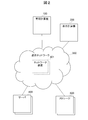
- the computer system of this embodiment includes a management computer 100, a display computer 200, a communication network 300, a server 400, and a storage 500. Each device is connected via a communication network 300.
- the management computer 100 is an information processing apparatus that manages the server 400 and the storage 500 connected via the communication network 300.
- the management computer 100 manages devices and components for each business management group or device management group in response to input from the business manager or device manager. Specifically, the management computer 100 acquires the state of the device or component and provides it to the display computer 200.
- a business administrator is an administrator who manages devices required for a certain business and the elements (components) that make up the device in groups.
- the device manager is a manager who manages a plurality of devices included in the system.
- the component is an element that constitutes the apparatus as described above, and includes not only a device dedicated to the apparatus but also a general-purpose apparatus element.
- Examples of the component include a logical unit (LU: Logical Unit) indicating an area obtained by logically dividing the disk drive, a port for inputting / outputting data, and the like.
- the business administrator adds information such as LU and port necessary for the business to the business group.
- the display computer 200 is composed of a display device or the like, and provides the status of managed devices and components acquired by the management computer 100 to the business administrator and device administrator.
- the management computer 100 and the display computer 200 are separate devices.
- the present invention is not limited to this example, and the management computer 100 and the display computer 200 may be configured as one device.
- the communication network 300 includes a plurality of network devices 301.
- a wired cable such as a copper wire or an optical fiber
- a data transmission path such as a radio wave
- data such as a router or a base station that controls communication. It is configured to include such as a repeater.
- the server 400 is an information processing apparatus that controls input / output of data to / from the storage 500, and performs writing and reading of data using a predetermined area provided by the storage 500.
- the storage 500 is an information processing apparatus that provides a storage area to the server 400.
- the storage 500 is a semiconductor memory such as an SSD (Solid State Drive), an SAS (Serial Attached SCSI) disk, or an FC (Fibre Channel) disk. It consists of a high-performance disk device and a low-cost and low-performance disk device such as a SATA (Serial AT Attachment) disk.
- SSD Solid State Drive
- SAS Serial Attached SCSI
- FC Fibre Channel
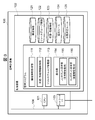
- the management computer 100 includes a CPU 101, a storage device 102, a network interface (denoted as network I / F in the figure) 103, a bus 104, and the like.
- the CPU 101 functions as an arithmetic processing device and a control device, and controls the overall operation in the management computer 100 according to various programs stored in the storage device 102. Further, the CPU 101 may be a microprocessor.
- the storage device 102 includes, for example, a ROM (Read Only Memory), a RAM (Random Access Memory), and the like, and stores a management program 110 having various functions and various management tables.
- the functions of the management program 110 include, for example, a configuration information acquisition unit 111, a state / performance information acquisition unit 112, a resource group management unit 113, a display unit 114, and the like.
- the management table includes configuration information 121, resource group information 122, state / performance information 123, an addition rule 124, a state determination rule 125, and the like.
- the configuration information acquisition unit 111 has a function of acquiring system configuration information including the server 400 and storage 500 managed by the management computer 100.
- the status / performance information acquisition unit 112 has a function of acquiring status information and performance information of the server 400 and the storage 500 configuring the system acquired by the configuration information acquisition unit 111.
- the resource group management unit 113 has a function of managing the status of each resource group set by an administrator, such as a device management group or a business management group.
- the display unit 114 has a function of providing various types of information to the administrator, and includes a component display unit 115 for business managers and a component display unit 116 for device managers.
- the component display units 115 and 116 have a function of displaying configuration information, status information, and the like of devices and components included in the business management group or device management group on the display screen.
- the configuration information 121 stores the system configuration information acquired by the configuration information acquisition unit 111.
- the configuration information 121 includes, for example, node configuration information, component configuration information, information indicating a relationship between components, and the like.
- the resource group information 122 stores information on resource groups registered by a business administrator or device administrator.
- the resource group information 122 includes information for managing members included in the resource group.
- the state / performance information 123 stores information such as the state and performance of components included in each resource group.
- the addition rule 124 stores information indicating a rule for adding a base component of a component registered in the resource group by the administrator.
- the state determination rule 125 stores information indicating a rule for determining the state of the component in consideration of the state of the base component.
- the network interface 103 is an interface for connecting to the communication network 300, and has a function of acquiring configuration information and status information of the server 400 and the storage 500.
- the bus 104 has a function of connecting devices in the management computer 100 such as the CPU 101 and the storage device 102 to each other.
- the display computer 200 includes a CPU 201, a storage device 202, a network interface (denoted as network I / F in the figure) 203, a bus 204, an input / output device 205, a display 206, and the like.
- a network interface denoted as network I / F in the figure
- the CPU 201 functions as an arithmetic processing device and a control device, and controls the overall operation in the display computer 200 according to various programs stored in the storage device 202. Further, the CPU 201 may be a microprocessor.
- the storage device 202 includes, for example, a ROM (Read Only Memory), a RAM (Random Access Memory), etc., and various programs such as a display result display program 211, display configuration information 221 and display status information 222, and the like. Various management tables are included.
- the display result display program 211 has a function of causing the display 206 to display component configuration information and status information acquired by the management computer 100 in units of groups registered by the administrator.
- the display configuration information 221 is information obtained by processing the component configuration information acquired by the management computer 100 for display.
- the display status information 222 is information obtained by processing the component status information acquired by the management computer 100 for display.
- the network interface 203 is an interface for connecting to the communication network 300, and has a function of acquiring configuration information and status information of the server 400 and the storage 500 from the management computer 100.
- the bus 104 has a function of connecting devices in the display computer 200 such as the CPU 201 and the storage device 202 to each other.
- the display 206 is a display device that displays the display configuration information 221, the display state / performance information 222, and the like as text or images.
- the computer system may include a plurality of servers 400 and a plurality of storages 500.
- FIG. 5 illustrates a case where a storage area provided to one storage 500 is used by two servers 400A and 400B.
- the server 400A includes a CPU 401, a memory 402, a first disk drive 403A, a second disk drive 403B, a third disk drive 403C, a power supply unit 404, and an agent 401.
- the CPU 401 functions as an arithmetic processing unit and a control unit, and controls the overall operation of the first server 400A according to various programs stored in the memory 402. Further, the CPU 401 may be a microprocessor.
- the memory 402 includes, for example, a ROM (Read Only Memory), a RAM (Random Access Memory), and the like.
- the first disk drive 403A, the second disk drive 403B, and the third disk drive 403C are drive devices that read and write data stored in the storage 500, and each disk drive is a logical volume of the storage 500. Assigned.
- the power supply unit 404 is a device that supplies power to the first server 400A. Further, the agent 401 monitors the status information of the server 400A and provides it to the management computer 100.
- the second server 400B has the same configuration as the first server 400A, detailed description thereof is omitted.
- the storage 500 includes parity groups 501A and 501B, a first controller 503A, a second controller 503B, a first power supply unit 504A, a second power supply unit 504B, and the like.
- Parity groups 501A and 501B are hard disk drive groups for realizing a RAID configuration.
- a RAID group is defined from a plurality of storage devices, and one or a plurality of volumes are defined on a storage area provided by one or a plurality of storage devices constituting one RAID group.
- a first volume 502A and a second volume 502B are defined in the parity group 501A
- a third volume 502C and a fourth volume 502D are defined in the parity group 501B.
- the first controller 503A and the second controller 503B have a function of managing the volumes on the hard disk, and the first controller 503A manages the first volume 502A and the second volume 502B, The controller 503B manages the third volume 502C and the fourth volume 502D.
- the first power supply unit 504A and the second power supply unit 504B are devices that supply power to the storage 500.
- a node such as a server and a component such as a volume necessary for execution of a predetermined business are registered as one business group.
- a node is a device such as a server or storage.
- a component indicates a function or component in a node.
- the business administrator can manage nodes and components by assigning them to resource groups (RG). For example, when a node called Server1 (first server 400A) and Volume1 (first volume 502A) are necessary to execute a business called Business, the user (business manager) is assigned to a business management group called Business. , Sever1 and Volume1 are assigned.
- CPU1 CPU 401
- Memory1 memory 402
- Disk1 first disk drive 403A
- ParityGroup1 parity group 501A
- Controller1 first controller 503A
- PowerUnit1 first power supply unit 504A
- PowerUnit2 second power supply unit 504B
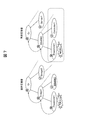
- FIG. 6 shows a tree structure to which nodes and components are added. The upper state of the tree structure depends on the lower state.
- higher-level components that have an influence on the nodes and components added to the business group by the business administrator, infrastructure components, and the like are automatically added according to a predetermined rule. Furthermore, the status information of the added component is acquired, and the status of the node and component necessary for the business is presented to the business manager, including the status of the base component that affects them.
- the component status can be changed and displayed according to the position of the administrator, information necessary for the device administrator and the business administrator to manage the device and the component is effective. Can be provided.
- the node table 601 is a table for managing the node configuration, and includes a node ID column 6011, a node type column 6012, and a status column 6013 as shown in FIG.
- the node ID column 6011 stores identification information for identifying a node.
- a node means a device that constitutes a computer system to be managed.
- the node type column 6012 stores information indicating the type of node. Examples of the node type include a server and a storage.
- the status column 6013 stores information indicating the status of the node. When the node is in a normal state, Normal indicating normal is stored, and when the node is not normal, Critical indicating abnormal is stored.
- FIG. 8 shows that, for example, the node type of the server 1 is the server (SERVER), and the state of the Server 1 is normal.
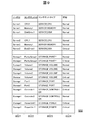
- the component table 602 is a table for managing the configuration of components, and includes a node ID column 6021, a component ID column 6022, a component type column 6023, and a status column 6024 as shown in FIG.
- the node ID column 6021 stores information for identifying the node.
- the component ID column 6022 stores information for identifying the component.
- a component means a function or component in a node as described above.
- the component type column 6023 stores information indicating the type of component. Examples of the component type include a CPU, a memory, a disk drive, and a logical volume.
- the status column 6024 stores information indicating the status of the component. When the component is in a normal state, Normal indicating normal is stored, and when the node is not normal, Critical indicating abnormal is stored.
- the type of the component of the CPU 1 which is the component constituting the node Server 1 is the server CPU (Server_CPU), and the state is normal.
- the component relation table 603 is a table for managing the dependency relationship of each component, and includes a node ID column 6031, a component ID column 6032, a relationship column 6033, and a related component ID column 6034 as shown in FIG. .
- the node ID column 6031 stores information for identifying the node.
- the component ID column 6032 stores information for identifying the component.
- the relationship column 6033 stores information indicating a relationship with a related component described later.
- information for identifying the component on which the component stored in the component ID column 6032 depends or is included is stored. For example, when the component in the component ID column 6032 depends on the component in the related component ID column 6032, Depend is stored in the related column 6033, and is included in the component in the related component ID column 6032 Stores On.
- ParityGroup1 which is a component constituting the node Storage1, depends on Rack1, and ParityGroup1 is a relationship (On) included in Rack1.
- the group member table 604 is a table for managing member information of each group, and includes a group ID column 6041, a member node ID column 6042, and a member component ID column 6043 as shown in FIG.
- the group ID column 6041 stores information for identifying a device group or a business group.
- the member node ID column 6042 stores identification information of nodes belonging to each group.
- the member component ID column 6043 stores identification information of the components constituting each node.
- the nodes belonging to the Device group are Server1, Server2, and Storage1. Further, it can be seen that the nodes belonging to the Business group (business management group) are Server1 and Storage1, and the component constituting Storage1 is Volume1.
- the component status management table 605 is a table for managing the status of the component. As shown in FIG. 12, the group ID column 6051, the node ID column 6052, the component ID column 6053, the rule ID column 6054, and the parent path name column. 6055, a quantification qualifier column 6056, a general column 6057, a base component status 6058, and a status column 6059.
- the group ID column 6051 stores information for identifying a device management group or a business management group.
- the node ID column 6052 stores information for identifying nodes belonging to each group.
- the component ID column 6053 stores information for identifying the components constituting each node.
- the rule ID column 6054 stores information for identifying a rule for adding a preset base component. The rules for adding the base component will be described later.
- the quantification qualifier column 6056 stores information indicating the basis for determining the overall state of the base component when there are a plurality of base components on which the component depends. For example, if there is a component that is not normal among one of the plurality of base components, Any indicating that the overall state of the base component is set to an abnormal state (critical) is stored. In addition, when all of the plurality of base components are not normal, All indicating that the overall state of the base components is set to an abnormal state (critical) is stored. Further, + n indicating that the total state of the base component is not normal (critical) is stored when n of the plurality of base components are not normal.
- the general column 6057 stores information indicating the state of the comprehensive base component determined by the quantification qualifier described above.
- the status column 6059 stores information indicating the status of each component.
- the base component is added by the rule 1 of the base component addition rule, the parent path name is / Volume1, and the quantification qualifier is Any, it can be seen that the state of the overall base component is Critical, the state of the base component is Critical, and the state of the component is Normal.
- the base component addition rule definition table 606 includes a rule ID field 6061, a component type field 6062, a component type field 6063 to be added, a quantification qualifier field 6064, a search method field 6065, a relation field 6066, and an additional field. It consists of a presence / absence column 6067.
- the rule ID column 6061 stores information for identifying a base component addition rule.
- the component type column 6062 stores information indicating the type of component.
- information indicating the type of component to be added as a base component of the component is stored according to the type of component.
- the quantification qualifier column 6064 stores information indicating the quantification qualifier described above.
- the search method field 6065 stores information indicating the search method, Order or Reverse.
- the relationship column 6066 stores information indicating the relationship between the component and the component to be added. When the component depends on the component to be added, Depend is stored, and when the component is included in the component to be added, On is stored. Information indicating whether or not to add a component to be added to the target component is stored in the addition presence / absence column 6067. For example, Y is stored when it is added, and N is stored when it is not added.
- 1 of the base component addition rule indicates a rule for the component type STORAGE_VOLUME, and the component type to be added is STORAGE_PARITYGROUP.
- the quantification qualifier of the STORAGE_PARITYGROUP to be added is Any, the search method is Order, the relationship (Depend) that depends on the component STORAGE_PARITYGROUP added by the component STORAGE_VOLUME (Depend), and it can be seen that it is a base component to be added to the component (Y) .
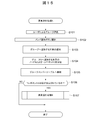
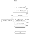
- the management program 110 of the management computer 100 executes a predetermined initialization process (S11), and then periodically (S12) based on the scheduler (S13) and status information acquisition process (S13) and status Update processing (S14) is executed.
- Configuration information acquisition processing for adding nodes and components to the device management group or the business management group is executed by the configuration information acquisition unit 111. As shown in FIG. 15, the configuration information acquisition unit 111 first executes element addition processing A to the group.
- the configuration information acquisition unit 111 selects a group according to a user input (S101). Then, a member addition button is selected according to the user input (S102), and the node N and node component C to be added to the group selected in step S101 are selected (S103).
- the configuration information acquisition unit 111 receives the node N and the component C of the element to be added to the group G selected in step S103 (S104). Then, the configuration information acquisition unit 111 registers the group ID of the group G, the node ID of the node N, and the component ID of the component C in the group member table 604 (S105).
- the configuration information acquisition unit 111 determines whether the value of the component C registered in step S105 is set (S106). If it is determined in step S105 that a value has been set for the component C, the configuration information acquisition unit 111 executes element addition processing B to the group (S107). On the other hand, if it is determined in step S105 that no value is set for the component C, the element is not a component, and the configuration information acquisition unit 111 ends the element addition process A.
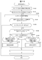
- the element addition process B in step S107 is a process for adding a base component to the added component when a component is added to the group in the element addition process A.
- the base component is added to each group based on the base component addition rule definition table 606.
- the configuration information acquisition unit 111 receives information on the element to be added to the group (S121).
- the information of the element added to the group is information such as a group ID, a node ID, a component ID, a parent path, or a quantification qualifier.
- the configuration information acquisition unit 111 determines whether or not its component ID is included in the parent path received in step S121 (S122). Further, in step S122, the configuration information acquisition unit 111 determines whether the component state management table 605 includes one that matches the received group ID, node ID, or component ID.
- the configuration information acquisition unit 111 ends the element addition process B. On the other hand, if it is determined in step S122 that the component ID is not included in the parent path, the configuration information acquisition unit 111 updates the component information management table (S123). Specifically, the configuration information acquisition unit 111 stores the information (group (GID), node (NID), component (CID), parent path or quantification qualifier) of the element to be added to the group received in step S121 in the component state. Stored in the management table 605.
- group group
- NID node
- CID component
- the configuration information acquisition unit 111 loops the process from step S124 to step S133 for each row R of the base component addition rule definition table 606.
- the configuration information acquisition unit 111 determines whether the component type of the component CID stored in the component state management table 605 in step S123 matches the component type of the row R (S125).
- the component type of the component CID can be acquired by referring to the component table 602. For example, it can be seen from the component table 602 that the component type of the node Storage1 and the component Volume1 is STORAGE_VOLUME. Then, in the base component addition rule definition table 606, it is determined whether there is a match with this component type (STORAGE_VOLUME).
- step S125 If it is determined in step S125 that the component types match, the process from step S126 to step S132 is looped. On the other hand, if it is determined in step S125 that the component types do not match, the loop processing from step S126 to step S132 ends.
- the configuration information acquisition unit 111 loops the process from step S127 to step S132 for each row C in the component table 603.
- the configuration information acquisition unit 111 determines whether the search method for the rule of the target row R in the base component addition rule definition table 606 is Order or Reverse (S127). In step S127, if the search method is Order, the processing from step S128 onward is executed from the left to the right of the tree structure of the group. On the other hand, if the search method is Reverse in step S127, the processing from step S129 onward is executed from right to left in the tree structure of the group.
- step S128 the configuration information acquisition unit 111 determines whether the component type and relationship in the component table matching the target component ID are the same as the component type and relationship in the base component addition rule definition table 606 (S128). ). If they match in step S128, the configuration information acquisition unit 111 executes element addition processing B (S130). In step S ⁇ b> 130, the configuration information acquisition unit 111 recursively calls the element addition process B as information on elements to add the group ID, node ID, related component ID, parent path, and quantification qualifier to the group.
- step S129 the configuration information acquisition unit 111 determines whether the component type and relationship of the component table matching the target component ID are the same as the component type and relationship of the base component addition rule definition table 606 (S129). ). If they match in step S129, the configuration information acquisition unit 111 executes element addition processing B (S131). In step S131, the configuration information acquisition unit 111 recursively calls the element addition process B as information on an element to add a group ID, node ID, related component ID, parent path, and quantification qualifier to the group.
- step S121 For example, if Volumu1 is added to the Business group by the user, “Business, Storage1, Volume1, /,-” is received in step S121. Since the parent path is “/”, “NO” is selected as the determination in step S122. In step S123, (Business, Storage1, Volume1, /,-) is stored in the component state management table 605.
- step S121 “Business, Storage1, ParityGroup1, / Volume1, Any” is received.
- step S122 “ParityGroup” is not included in the parent path “/ Volume1”, and the component status management table 605 includes GID, Since a match between NID and CID is not included, “NO” is selected for determination.
- step S123 “Business, Storage1, ParityGroup1, / Volume1, Any” is stored in the component state management table 605.
- the element addition process B is repeated until the base component to be added to the management group is not found, and the component state management table 605 is updated. Will be.
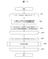
- the status / performance information acquisition unit 112 acquires the status and performance of each device and component. As shown in FIG. 17, the state / performance information acquisition unit 112 loops the processing of steps S21 to S27 for each node N in the node table 601. The loop process shown in FIG. 17 is periodically executed at predetermined intervals.
- the state / performance information acquisition unit 112 acquires the state information of the components constituting the node N from the node N, and updates the state information of the components related to the node N in the component table 602 (S22).
- the status / performance information acquisition unit 112 sets the worst value of the status of the component of the same node N in the component table 602 as the status information of the node N in the node table 601.
- the state / performance information acquisition unit 112 loops the state update processing A in step S26 for each row GM of the group member table 604 (S26).
- the loop processing in step S26 is completed (S27), the state / performance information processing is terminated.
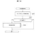
- step S26 The state update process A in step S26 will be described.
- the state / performance information acquisition unit 112 receives information on the members added to the group (S201).
- the state / performance information acquisition unit 112 receives the group ID (GID) of the group, the node ID (NID) added to the group, and the component ID (CID) (S201).
- GID group ID
- NID node ID
- CID component ID
- the state / performance information acquisition unit 112 determines whether the component ID (CID) of the member information received in step S201 is an empty value (S202).
- the case where the component ID is a null value indicates that the element added to the group is a node. That is, in step S202, it is determined whether the element to be added to the group is a node or a component.
- step S202 If it is determined in step S202 that the component ID (CID) is a null value, the state / performance information acquisition unit 112 ends the state update process A. On the other hand, if it is determined in step S202 that the component ID (CID) is not a null value, state update processing B is executed (S203). That is, when the element to be added to the group is a component, a process (state update process B) for grasping the state of the base component of the component is executed.
- the state / performance information acquisition unit 112 receives information on an element to be added to the group (S211). Specifically, the state / performance information acquisition unit 112 receives group ID (GID), node ID (NID), component ID (CID), and parent path information.
- GID group ID
- NID node ID
- CID component ID
- the status / performance information acquisition unit 112 performs processing from step S213 to step S222 for the component C having the same value as the “parent path / CID” received in step S211 with the parent path name in the component status management table 605. Loop.
- step S213 the state / performance information acquisition unit 112 recursively calls the state update processing B for the component C in the component information management table corresponding to the parent path name “parent path / CID” after the loop processing.
- the state / performance information acquisition unit 112 refers to the component state management table 605 to determine the quantification qualifier of the component C (S214). In step S214, if the quantification qualifier of component C is Any, the processing from step S215 is executed. On the other hand, if the quantification qualifier of component C is All in step S214, the processing from step S216 is executed.
- step S215 the state / performance information acquisition unit 112 acquires an element W having a matching MyPath and rule from the work table 607 shown in FIG. Then, the state / performance information acquisition unit 112 determines whether or not the element W having the matching MyPath and rule exists in the work table 607 (S217).
- the work table 607 is a work table temporarily stored in the storage device of the management computer 100. As shown in FIG. 20, the work table 607 includes a MyPath column 6071, a rule ID column 6072, and a value column 6073. In each column, information at the time of update processing in the state configuration processing B is temporarily stored.
- the MyPath column 6071 stores the parent path of the component being updated.
- the rule ID column 6072 stores the identification information of the base component addition rule for the component being updated.
- the value column 6073 stores information indicating the status of the component being updated.
- step S217 If it is determined in step S217 that the element W exists in the work table 607, the state / performance information acquisition unit 112 compares the state of the target component with the value of the work table, and sets the work table with a bad value. The value in the value column 6073 of 607 is updated.
- the state / performance information acquisition unit 112 registers the element W in the work table 607 (S219). Specifically, the status / performance information acquisition unit 112 stores the value of the path name field 605 of the parent of the component that is the target of the component status management table 605 in MyPath 6071 of the work table 607. Further, the value of the rule ID column 6054 of the component state management table 605 is stored in the rule ID column 6072 of the work table 607. Further, the value of the status column 6059 of the component status management table 605 is stored in the value column 6073 of the work table 607.
- step S216 the state / performance information acquisition unit 112 acquires the element W having the matching MyPath and rule from the work table 607 shown in FIG. Then, the state / performance information acquisition unit 112 determines whether an element W having matching MyPath and rule exists in the work table 607 (S218).
- step S218 If it is determined in step S218 that the element W exists in the work table 607, the state / performance information acquisition unit 112 compares the state of the target component with the value of the work table, and sets the work table with a good value. The value in the value column 6073 of 607 is updated.
- step S218 when it is determined in step S218 that the element W does not exist in the work table 607, the state / performance information acquisition unit 112 registers the element W in the work table 607 (S219).
- the state / performance information acquisition unit 112 has the worst value of the values of each row in which the value of the MyPath column 6071 of the work table 607 matches the “parent path / component ID”. Is set as the value of the base component state (S223). Specifically, the state / performance information acquisition unit 112 uses the worst value of the values in each row where the value in the MyPath column 6071 of the work table 607 matches “parent path / component ID” as the group ID in the component status management table 605. , The node ID, and the component ID are stored in the base component status column 6058 in the row that matches the component ID.
- the state / performance information acquisition unit 112 deletes the line in which MyPath matches “parent path / CID” from the work table 607 (S224).
- Step S211 when the management group element information “Bussines, Storage1, Volume1, /” is received in step S211, the “parent path name” value equal to the parent path / component ID “/ Volume1” in the component status management table 605 is obtained.
- Steps S212 to S222 are looped for “ParityGroup1” having Further, steps S212 to S222 are looped for “PowerUnit1” having a “parent path name” value equal to “/ Volume1 / ParityGroup1”.
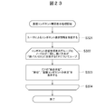
- the display unit 114 executes display processing for causing the display computer 200 to display the state information of the nodes and components of the device management group or the business management group.
- the display unit 114 receives group selection information (group ID: GID) according to the user input (S301).
- the display unit 114 performs a loop process from step S302 to step S306 for the element group member (GM) of the group member table 604 that matches the group ID received in step S301.
- the display unit 114 determines whether or not the member component ID column 6043 of the group member table 604 is an empty value (S303). If the member component ID column 6043 is a null value, it indicates that the member element is a node.
- step S303 If it is determined in step S303 that the member component ID column 6043 is a null value, the row N of the node table 601 that matches the value in the member node ID column 6042 of the group member table 604 is acquired, and the display screen The value in the status column 6013 of line N is displayed in the Status column and the overall (Status) column (S304).
- step S303 if it is determined in step S303 that the member component ID column 6043 is not null, the row of the component status management table 605 that matches the group ID, group member node ID, group member component ID, and “/”. C is acquired and the acquired information is displayed on the display screen (S305).
- the display unit 114 receives member selection information in response to user input (S311). Specifically, the display unit 114 receives a group ID (GID), a node ID (NID), and a content ID (CID).
- GID group ID
- NID node ID
- CID content ID
- the display part 114 determines whether content ID (CID) is an empty value among the information received in step S311 (S312). If the content ID is a null value, it can be seen that the element is a node.
- CID content ID
- step S312 When it is determined in step S312 that the content ID (CID) is a null value, the display unit 114 performs a loop process from step S313 to step S315 for the component C having the node ID selected by the user.
- the display unit 114 displays the status information of the component C in the component table 602 of the selected component in the general status column and the status column of the display screen (S314).
- step S312 if it is determined in step S312 that the component ID (CID) is not a null value, the display unit 114 executes a base component expansion display process for the target component (S316).
- the display unit 114 receives the component selection information (group ID, node ID, component ID, parent path) selected according to the user input (S321).
- step S323 is looped for the row F in which the group ID and node ID of the component status management table 605 match and the parent path name matches “parent path / CID”.
- step S323 the display unit 114 displays the status information stored in the general column 6057, the base component status column 6058, and the status column 6059 in the row F of the component status management table 605, respectively. Is displayed on the display screen.
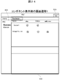
- FIG. 24 is an example of a component display screen 500 that displays components.
- the component display screen 500 includes a menu column 501 and a status display column 502.
- the menu column 501 displays a list of resource groups (RG) such as device management groups and business management groups registered in response to user input.
- RG resource groups
- the status display field 502 the names of nodes and components and the status of the nodes or components are displayed in association with each other.
- the state of a node or content includes an overall state of the node or component, a single state, a state of a base component, or the like.
- the business which is the business management group
- the business management group Business is executed by the group display process shown in FIG.
- the node Server1 and the component Storage1 / Volume1 added to are displayed, and their status information is displayed.
- Storage1 / Volume1 is in a state that is not normal in general, but Volume1 of Storage1 itself is not a failure, and it can be seen that among the base components, PowerUnit1 and PowerUnit2 are failures.
- the state information of the base component is displayed on the same screen as the screen on which the nodes and components are displayed, but is not limited to this example, and is displayed on a separate screen. May be displayed.
- the component and the base component are displayed on the upper and lower portions of one screen, but may be displayed on the left and right portions of one screen.
- Storage1 As shown in FIG. 27, the components constituting Storage1 are Volume1, Volume2, Volume3, PowerUnit1, PowerUnit2, etc., and it can be seen that Storage1 is not normal and that PowerUnit1 and PowerUnit2 are faulty.
- the component status can be changed and displayed depending on the manager's position, such as a business manager or device manager.
- a manager's position such as a business manager or device manager.
- the component display screen 510 displayed for the business administrator in FIG. 25 it is displayed so that the volume 1 of Storage 1 is not in a normal state and that the cause is the base component.
- the component display screen 530 displayed to the device administrator in FIG. 27 it is displayed so that it can be seen that Storage1 is not normal, each volume is normal, and the power supply unit has a failure. Yes.
- a node (monitored device) or component is assigned to a business management group or device management group (monitored group) in response to an input from the business administrator or device manager. If the component status is displayed via the monitoring target group when a failure occurs in the base component of the component, the component is displayed in an abnormal state and the component is displayed without going through the monitoring target group. Is displayed, it is displayed that the component is in a normal state and the node or the base component is in an abnormal state. As a result, the devices related to the management target of the administrator and the elements constituting the device are identified, and the status information of the management target including these states is provided to efficiently grasp the influence on the management target at the time of failure. can do.
Landscapes
- Engineering & Computer Science (AREA)
- Theoretical Computer Science (AREA)
- Physics & Mathematics (AREA)
- Quality & Reliability (AREA)
- General Engineering & Computer Science (AREA)
- General Physics & Mathematics (AREA)
- Computing Systems (AREA)
- Mathematical Physics (AREA)
- Debugging And Monitoring (AREA)
- User Interface Of Digital Computer (AREA)
Abstract
Description
まず、本実施形態の概要について説明する。従来、サーバ、ストレージ及びネットワーク機器といったネットワークを構成するノード単位でその稼働を監視することが行われている。また、サーバやストレージなどの装置単位や、サーバやサーバを構成する論理ボリュームやポートなどの要素(以下これをコンポネントと称して説明する。)を含む業務単位でその稼働を監視することも行われている。
(2-1)計算機システムのハードウェア構成
次に、計算機システムのハードウェア構成について説明する。図2に示すように、本実施の形態の計算機システムは、管理計算機100と、表示計算機200と、通信ネットワーク300と、サーバ400と、ストレージ500とから構成される。各装置は通信ネットワーク300を介して接続されている。
次に、図3を参照して、管理計算機100の構成について説明する。図3に示すように、管理計算機100は、CPU101、記憶装置102、ネットワークインタフェース(図中ネットワークI/Fと表記)103及びバス104などから構成される。
次に、図4を参照して、表示計算機200の構成について説明する。図4に示すように、表示計算機200は、CPU201、記憶装置202、ネットワークインタフェース(図中ネットワークI/Fと表記)203、バス204、入出力デバイス205及びディスプレイ206などから構成される。
次に、図5を参照してサーバ400及びストレージ500の構成を説明する。図2に示すように、計算機システムには、複数のサーバ400及び複数のストレージ500が含まれていてもよい。図5では、1つのストレージ500に提供される記憶領域を2つのサーバ400A及び400Bで利用する場合について説明する。
次に、管理計算機100の記憶装置102に記憶されている各種管理テーブルについて説明する。
次に、管理計算機100によるコンポネント追加処理について説明する。まず、図14を参照して、全体処理について説明する。図14に示すように、管理計算機100の管理プログラム110は、所定の初期化処理を実行した後(S11)、スケジューラをもとに定期的に(S12)、構成情報取得処理(S13)及び状態更新処理(S14)を実行する。
本実施形態によれば、業務管理者または装置管理者の入力に応じて、業務管理グループまたは装置管理グループ(監視対象グループ)にノード(監視対象装置)またはコンポネントを追加し、コンポネントの基盤コンポネントに障害が発生した場合に、監視対象グループを介してコンポネントの状態を表示させる場合には、コンポネントが異常状態であることを表示させ、監視対象グループを介さずにコンポネントの状態を表示させる場合には、コンポネントが正常状態であり、ノードまたは基盤コンポネントが異常状態であることを表示させる。これにより、管理者の管理対象に関係する装置及び装置を構成する要素を特定し、これらの状態を加味した管理対象の状態情報を提供して、障害時の管理対象への影響を効率よく把握することができる。
111 構成情報取得部
112 性能情報取得部
113 リソースグループ管理部
114 表示部
200 表示計算機
211 表示用結果表示プログラム
300 通信ネットワーク
400 サーバ
500 ストレージ
Claims (8)
- 複数の監視対象装置を監視する情報処理装置は、
前記監視対象装置の構成情報及び状態情報を記憶する記憶部と、
前記監視対象装置及び前記監視対象装置を構成する機能や部品を含むコンポネントの状態情報を監視する制御部と、
前記コンポネントの状態情報を表示させる表示部と、
を備え、
前記制御部は、
監視ユーザの入力に応じて、前記監視対象装置または該監視対象装置のコンポネントを含む1つ以上の監視対象グループを定義し、
前記監視対象グループに第1のコンポネントが含まれており、第2のコンポネントに障害が発生し、前記第1のコンポネントと前記第2のコンポネントに特定の関係がある場合、
前記監視対象グループを介して前記第1のコンポネントの状態を表示させる場合には、前記第1のコンポネントが異常状態であることを表示させ、
前記監視対象グループを介さずに前記第1のコンポネントの状態を表示させる場合には、前記第1のコンポネントが正常状態であり、前記第1の監視対象装置または前記第2のコンポネントが異常状態であることを表示させる
ことを特徴とする、情報処理装置。 - 前記制御部は、
前記監視ユーザの入力に応じて、前記監視対象グループに前記第1のコンポネントを追加した場合に、
所定のルールにしたがって、前記第1のコンポネントの機能の提供に影響を与える前記第2のコンポネントを検索し、
前記第2のコンポネントを前記第1のコンポネントの基盤コンポネントとして前記監視対象グループに追加する
ことを特徴とする、請求項1に記載の情報処理装置。 - 前記制御部は、
前記監視対象グループに、前記第1のコンポネントとして複数の前記基盤コンポネントが追加され、複数の前記基盤コンポネントのいずれかに障害が発生した場合に、
前記第1のコンポネントの状態を表示させるとともに、複数の前記基盤コンポネントの状態を集約して表示させる
ことを特徴とする、請求項2に記載の情報処理装置。 - 前記表示部は、
前記監視ユーザの入力に応じて前記監視対象グループとして定義された前記第1のコンポネントを表示し、
前記監視ユーザが、前記表示部に表示された前記第1のコンポネントを選択した場合に、前記第1のコンポネントの前記基盤コンポネントとして前記監視対象グループに追加された前記第2のコンポネントの状態を表示する、
ことを特徴とする、請求項3に記載の情報処理装置。 - 前記記憶部は、
前記基盤コンポネントを前記監視対象グループに追加するための所定のルールとして、前記所定のコンポネントの種類と、該コンポネントの前記基盤コンポネントの種類とを対応づけてルール定義表に格納し、
前記コンポネントと前記コンポネントに前記基盤コンポネントを追加するための所定のルールのうちのいずれかを対応付けてコンポネント状態管理表に格納し、
前記制御部は、
前記コンポネント状態管理表にしたがって、前記コンポネントに対応する所定のルールを決定し、前記ルール定義表の前記所定のルールにしたがって、前記第1のコンポネントの機能の提供に影響を与える前記第2のコンポネントを検索し、
前記第2のコンポネントを前記第1のコンポネントの基盤コンポネントとして前記監視対象グループに追加する
ことを特徴とする、請求項2に記載の情報処理装置。 - 前記記憶部は、
前記監視対象装置と、前記監視対象装置のコンポネントと、前記監視対象装置のコンポネントに関係するコンポネントとを対応付けてコンポネント関係テーブルに記憶し、
前記制御部は、
前記監視ユーザの入力に応じて、前記監視対象グループに前記コンポネントが追加された場合に、
前記ルール定義表を参照して前記コンポネントの種類に対応する所定のルールを決定し、
前記コンポネント関係テーブルを参照して前記コンポネントに関係するコンポネントを取得し、
前記所定のルールにしたがって、前記取得した前記コンポネントに関係するコンポネントを前記コンポネントの基盤コンポネントとして前記監視対象グループに追加するかを決定する
ことを特徴とする、請求項5に記載の情報処理装置。 - 前記制御部は、
前記監視ユーザの入力に応じて、前記監視対象グループに前記監視対象装置が追加された場合には、前記監視対象装置を構成するコンポネントを前記監視対象グループに追加する
ことを特徴とする、請求項6に記載の情報処理装置。 - コンピュータを、
複数の監視対象装置を監視する情報処理装置であって、
前記監視対象装置の構成情報及び状態情報を記憶する記憶部と、
前記監視対象装置及び前記監視対象装置を構成する機能や部品を含むコンポネントの状態情報を監視する制御部と、
前記コンポネントの状態情報を表示させる表示部と、
を備え、
前記制御部は、
監視ユーザの入力に応じて、前記監視対象装置または該監視対象装置のコンポネントを含む1つの監視対象グループを定義し、
前記監視対象グループに第1のコンポネントが含まれており、第2のコンポネントに障害が発生し、前記第1のコンポネントと前記第2のコンポネントに特定の関係がある場合、
前記監視対象グループを介して前記第1のコンポネントの状態を表示させる場合には、前記第1のコンポネントが異常状態であることを表示させ、
前記監視対象グループを介さずに前記第1のコンポネントの状態を表示させる場合には、前記第1のコンポネントが正常状態であり、前記第1の監視対象装置または前記第2のコンポネントが異常状態であることを表示させる
情報処理装置として機能させるための、プログラム。
Priority Applications (3)
| Application Number | Priority Date | Filing Date | Title |
|---|---|---|---|
| US14/428,097 US20150227408A1 (en) | 2012-11-02 | 2012-11-02 | Information processing unit and program |
| JP2014544184A JP5938482B2 (ja) | 2012-11-02 | 2012-11-02 | 情報処理装置及びプログラム |
| PCT/JP2012/078534 WO2014068773A1 (ja) | 2012-11-02 | 2012-11-02 | 情報処理装置及びプログラム |
Applications Claiming Priority (1)
| Application Number | Priority Date | Filing Date | Title |
|---|---|---|---|
| PCT/JP2012/078534 WO2014068773A1 (ja) | 2012-11-02 | 2012-11-02 | 情報処理装置及びプログラム |
Publications (1)
| Publication Number | Publication Date |
|---|---|
| WO2014068773A1 true WO2014068773A1 (ja) | 2014-05-08 |
Family
ID=50626736
Family Applications (1)
| Application Number | Title | Priority Date | Filing Date |
|---|---|---|---|
| PCT/JP2012/078534 Ceased WO2014068773A1 (ja) | 2012-11-02 | 2012-11-02 | 情報処理装置及びプログラム |
Country Status (3)
| Country | Link |
|---|---|
| US (1) | US20150227408A1 (ja) |
| JP (1) | JP5938482B2 (ja) |
| WO (1) | WO2014068773A1 (ja) |
Cited By (1)
| Publication number | Priority date | Publication date | Assignee | Title |
|---|---|---|---|---|
| WO2015189957A1 (ja) * | 2014-06-12 | 2015-12-17 | 株式会社日立製作所 | 性能情報管理システム、管理計算機、および性能情報管理方法 |
Citations (3)
| Publication number | Priority date | Publication date | Assignee | Title |
|---|---|---|---|---|
| JP2000181756A (ja) * | 1998-12-18 | 2000-06-30 | Fuji Xerox Co Ltd | 状態表示方法および装置 |
| JP2004062741A (ja) * | 2002-07-31 | 2004-02-26 | Nec Corp | 障害情報表示装置及びプログラム |
| JP2007164494A (ja) * | 2005-12-14 | 2007-06-28 | Hitachi Ltd | 情報出力方法、システム及びプログラム |
Family Cites Families (10)
| Publication number | Priority date | Publication date | Assignee | Title |
|---|---|---|---|---|
| US6243746B1 (en) * | 1998-12-04 | 2001-06-05 | Sun Microsystems, Inc. | Method and implementation for using computer network topology objects |
| US7197561B1 (en) * | 2001-03-28 | 2007-03-27 | Shoregroup, Inc. | Method and apparatus for maintaining the status of objects in computer networks using virtual state machines |
| JP2004362144A (ja) * | 2003-06-03 | 2004-12-24 | Hitachi Ltd | 運用管理方法及び実施装置並びに処理プログラム |
| JP3808893B1 (ja) * | 2005-07-14 | 2006-08-16 | 国立大学法人 岡山大学 | 故障診断装置、プログラム及び記録媒体 |
| US8156378B1 (en) * | 2010-10-15 | 2012-04-10 | Red Hat, Inc. | System and method for determination of the root cause of an overall failure of a business application service |
| JP5066169B2 (ja) * | 2009-12-15 | 2012-11-07 | 株式会社日立製作所 | 業務監視装置、業務監視方法および業務監視プログラム |
| WO2012014305A1 (ja) * | 2010-07-29 | 2012-02-02 | 株式会社日立製作所 | システム障害における構成変更事象の影響度推定方法 |
| JP5731223B2 (ja) * | 2011-02-14 | 2015-06-10 | インターナショナル・ビジネス・マシーンズ・コーポレーションInternational Business Machines Corporation | 異常検知装置、監視制御システム、異常検知方法、プログラムおよび記録媒体 |
| JP5800537B2 (ja) * | 2011-03-18 | 2015-10-28 | 株式会社日立製作所 | 旅客流動予測装置 |
| US20130297603A1 (en) * | 2012-05-01 | 2013-11-07 | Fujitsu Technology Solutions Intellectual Property Gmbh | Monitoring methods and systems for data centers |
-
2012
- 2012-11-02 WO PCT/JP2012/078534 patent/WO2014068773A1/ja not_active Ceased
- 2012-11-02 JP JP2014544184A patent/JP5938482B2/ja active Active
- 2012-11-02 US US14/428,097 patent/US20150227408A1/en not_active Abandoned
Patent Citations (3)
| Publication number | Priority date | Publication date | Assignee | Title |
|---|---|---|---|---|
| JP2000181756A (ja) * | 1998-12-18 | 2000-06-30 | Fuji Xerox Co Ltd | 状態表示方法および装置 |
| JP2004062741A (ja) * | 2002-07-31 | 2004-02-26 | Nec Corp | 障害情報表示装置及びプログラム |
| JP2007164494A (ja) * | 2005-12-14 | 2007-06-28 | Hitachi Ltd | 情報出力方法、システム及びプログラム |
Cited By (2)
| Publication number | Priority date | Publication date | Assignee | Title |
|---|---|---|---|---|
| WO2015189957A1 (ja) * | 2014-06-12 | 2015-12-17 | 株式会社日立製作所 | 性能情報管理システム、管理計算機、および性能情報管理方法 |
| US10078452B2 (en) | 2014-06-12 | 2018-09-18 | Hitachi Ltd. | Performance information management system, management computer, and performance information management method |
Also Published As
| Publication number | Publication date |
|---|---|
| JPWO2014068773A1 (ja) | 2016-09-08 |
| JP5938482B2 (ja) | 2016-06-22 |
| US20150227408A1 (en) | 2015-08-13 |
Similar Documents
| Publication | Publication Date | Title |
|---|---|---|
| US9684450B2 (en) | Profile-based lifecycle management for data storage servers | |
| US8832498B1 (en) | Scalable codebook correlation for cloud scale topology | |
| US9619311B2 (en) | Error identification and handling in storage area networks | |
| CN107431643B (zh) | 用于监测存储集群元件的方法和装置 | |
| US7007144B2 (en) | Method, apparatus, and computer readable medium for managing back-up | |
| US7127545B1 (en) | System and method for dynamically loadable storage device I/O policy modules | |
| US7609654B2 (en) | Method of evaluating network connectivity between network resources | |
| US9354961B2 (en) | Method and system for supporting event root cause analysis | |
| US7921325B2 (en) | Node management device and method | |
| US7702962B2 (en) | Storage system and a method for dissolving fault of a storage system | |
| US8949653B1 (en) | Evaluating high-availability configuration | |
| US8639808B1 (en) | Method and apparatus for monitoring storage unit ownership to continuously balance input/output loads across storage processors | |
| US10019163B2 (en) | Policy based storage in a heterogeneous storage environment | |
| US9736046B1 (en) | Path analytics using codebook correlation | |
| US9201740B2 (en) | Computer system, cluster management method, and management computer | |
| WO2011118051A1 (ja) | 計算機システムにおけるシステム管理方法、及び管理システム | |
| US10536329B2 (en) | Assisted configuration of data center infrastructure | |
| US7930583B1 (en) | System and method for domain failure analysis of a storage area network | |
| US9021078B2 (en) | Management method and management system | |
| US8489721B1 (en) | Method and apparatus for providing high availabilty to service groups within a datacenter | |
| US8583789B2 (en) | Computer system management method and management apparatus | |
| JP6259547B2 (ja) | 管理システム、及び、管理方法 | |
| JP5938482B2 (ja) | 情報処理装置及びプログラム | |
| US8671186B2 (en) | Computer system management method and management apparatus | |
| US20160294934A1 (en) | Resource management in distributed computer systems using dispersion rules |
Legal Events
| Date | Code | Title | Description |
|---|---|---|---|
| 121 | Ep: the epo has been informed by wipo that ep was designated in this application |
Ref document number: 12887798 Country of ref document: EP Kind code of ref document: A1 |
|
| ENP | Entry into the national phase |
Ref document number: 2014544184 Country of ref document: JP Kind code of ref document: A |
|
| WWE | Wipo information: entry into national phase |
Ref document number: 14428097 Country of ref document: US |
|
| NENP | Non-entry into the national phase |
Ref country code: DE |
|
| 122 | Ep: pct application non-entry in european phase |
Ref document number: 12887798 Country of ref document: EP Kind code of ref document: A1 |