WO2014050519A1 - Massive fiber body, and artificial soil produced using massive fiber body - Google Patents
Massive fiber body, and artificial soil produced using massive fiber body Download PDFInfo
- Publication number
- WO2014050519A1 WO2014050519A1 PCT/JP2013/074198 JP2013074198W WO2014050519A1 WO 2014050519 A1 WO2014050519 A1 WO 2014050519A1 JP 2013074198 W JP2013074198 W JP 2013074198W WO 2014050519 A1 WO2014050519 A1 WO 2014050519A1
- Authority
- WO
- WIPO (PCT)
- Prior art keywords
- water
- fiber
- core part
- soil
- fibers
- Prior art date
Links
Images


Classifications
-
- C—CHEMISTRY; METALLURGY
- C05—FERTILISERS; MANUFACTURE THEREOF
- C05F—ORGANIC FERTILISERS NOT COVERED BY SUBCLASSES C05B, C05C, e.g. FERTILISERS FROM WASTE OR REFUSE
- C05F11/00—Other organic fertilisers
-
- A—HUMAN NECESSITIES
- A01—AGRICULTURE; FORESTRY; ANIMAL HUSBANDRY; HUNTING; TRAPPING; FISHING
- A01G—HORTICULTURE; CULTIVATION OF VEGETABLES, FLOWERS, RICE, FRUIT, VINES, HOPS OR SEAWEED; FORESTRY; WATERING
- A01G24/00—Growth substrates; Culture media; Apparatus or methods therefor
- A01G24/40—Growth substrates; Culture media; Apparatus or methods therefor characterised by their structure
- A01G24/42—Growth substrates; Culture media; Apparatus or methods therefor characterised by their structure of granular or aggregated structure
-
- A—HUMAN NECESSITIES
- A01—AGRICULTURE; FORESTRY; ANIMAL HUSBANDRY; HUNTING; TRAPPING; FISHING
- A01G—HORTICULTURE; CULTIVATION OF VEGETABLES, FLOWERS, RICE, FRUIT, VINES, HOPS OR SEAWEED; FORESTRY; WATERING
- A01G24/00—Growth substrates; Culture media; Apparatus or methods therefor
-
- A—HUMAN NECESSITIES
- A01—AGRICULTURE; FORESTRY; ANIMAL HUSBANDRY; HUNTING; TRAPPING; FISHING
- A01G—HORTICULTURE; CULTIVATION OF VEGETABLES, FLOWERS, RICE, FRUIT, VINES, HOPS OR SEAWEED; FORESTRY; WATERING
- A01G31/00—Soilless cultivation, e.g. hydroponics
-
- C—CHEMISTRY; METALLURGY
- C05—FERTILISERS; MANUFACTURE THEREOF
- C05G—MIXTURES OF FERTILISERS COVERED INDIVIDUALLY BY DIFFERENT SUBCLASSES OF CLASS C05; MIXTURES OF ONE OR MORE FERTILISERS WITH MATERIALS NOT HAVING A SPECIFIC FERTILISING ACTIVITY, e.g. PESTICIDES, SOIL-CONDITIONERS, WETTING AGENTS; FERTILISERS CHARACTERISED BY THEIR FORM
- C05G5/00—Fertilisers characterised by their form
- C05G5/30—Layered or coated, e.g. dust-preventing coatings
- C05G5/37—Layered or coated, e.g. dust-preventing coatings layered or coated with a polymer
-
- C—CHEMISTRY; METALLURGY
- C09—DYES; PAINTS; POLISHES; NATURAL RESINS; ADHESIVES; COMPOSITIONS NOT OTHERWISE PROVIDED FOR; APPLICATIONS OF MATERIALS NOT OTHERWISE PROVIDED FOR
- C09K—MATERIALS FOR MISCELLANEOUS APPLICATIONS, NOT PROVIDED FOR ELSEWHERE
- C09K17/00—Soil-conditioning materials or soil-stabilising materials
- C09K17/14—Soil-conditioning materials or soil-stabilising materials containing organic compounds only
- C09K17/18—Prepolymers; Macromolecular compounds
- C09K17/32—Prepolymers; Macromolecular compounds of natural origin, e.g. cellulosic materials
-
- D—TEXTILES; PAPER
- D06—TREATMENT OF TEXTILES OR THE LIKE; LAUNDERING; FLEXIBLE MATERIALS NOT OTHERWISE PROVIDED FOR
- D06M—TREATMENT, NOT PROVIDED FOR ELSEWHERE IN CLASS D06, OF FIBRES, THREADS, YARNS, FABRICS, FEATHERS OR FIBROUS GOODS MADE FROM SUCH MATERIALS
- D06M15/00—Treating fibres, threads, yarns, fabrics, or fibrous goods made from such materials, with macromolecular compounds; Such treatment combined with mechanical treatment
- D06M15/19—Treating fibres, threads, yarns, fabrics, or fibrous goods made from such materials, with macromolecular compounds; Such treatment combined with mechanical treatment with synthetic macromolecular compounds
- D06M15/21—Macromolecular compounds obtained by reactions only involving carbon-to-carbon unsaturated bonds
-
- A—HUMAN NECESSITIES
- A01—AGRICULTURE; FORESTRY; ANIMAL HUSBANDRY; HUNTING; TRAPPING; FISHING
- A01G—HORTICULTURE; CULTIVATION OF VEGETABLES, FLOWERS, RICE, FRUIT, VINES, HOPS OR SEAWEED; FORESTRY; WATERING
- A01G24/00—Growth substrates; Culture media; Apparatus or methods therefor
- A01G24/30—Growth substrates; Culture media; Apparatus or methods therefor based on or containing synthetic organic compounds
- A01G24/35—Growth substrates; Culture media; Apparatus or methods therefor based on or containing synthetic organic compounds containing water-absorbing polymers
-
- C—CHEMISTRY; METALLURGY
- C09—DYES; PAINTS; POLISHES; NATURAL RESINS; ADHESIVES; COMPOSITIONS NOT OTHERWISE PROVIDED FOR; APPLICATIONS OF MATERIALS NOT OTHERWISE PROVIDED FOR
- C09K—MATERIALS FOR MISCELLANEOUS APPLICATIONS, NOT PROVIDED FOR ELSEWHERE
- C09K2101/00—Agricultural use
Definitions
- the present invention relates to a fiber lump formed by collecting fibers and artificial soil using the fiber lump.
- the fiber lump formed by collecting the fibers has voids formed between the fibers, the voids can contain moisture while being lightweight. For this reason, a fiber lump can be utilized as a water retention material.
- the fiber lump may be used, for example, by supporting a catalyst or a useful microorganism in the gap between the fibers. Therefore, taking advantage of the characteristics of the voids between the fibers, the fiber aggregate is used, for example, as artificial soil in the agricultural field and as a water treatment carrier in the environmental field.
- artificial soil may be used for greening in outdoor spaces such as the rooftops of buildings, verandas in condominiums, and indoor spaces such as lobbies and living rooms.
- outdoor spaces such as the rooftops of buildings, verandas in condominiums, and indoor spaces such as lobbies and living rooms.
- artificial soil is used instead of natural soil.
- natural soil is used for greening indoor spaces, there is a concern that it may be difficult to relocate the plant due to its weight, or that microorganisms will grow in the natural soil and the indoors will become unsanitary. This is because that.
- the fiber lump is light in weight as compared with natural soil of the same volume, has good drainage properties, and is hygienic, so it can be said that it is a suitable material for artificial soil.
- Patent Document 1 proposes a horticultural fiber sphere obtained by molding palm fibers into a spherical shape.
- Patent Document 2 proposes a natural pulp obtained by solidifying a natural pulp with a resin or a paste and then pulverizing the solid as a substitute for natural soil.
- the horticultural fiber sphere of Patent Document 1 retains water supplied from the outside in hydrophilic palm fibers so that the water can be used by plants.
- this fiber sphere for gardening does not have sufficient strength because the palm fiber is simply formed into a simple spherical shape.
- the palm fiber is exposed, there is a risk that moisture is immediately lost when the external environment is dried.
- the plant cultivation apparatus of Patent Document 2 uses, as an alternative to natural soil, a crushed material obtained by crushing a solid material obtained by solidifying natural pulp with resin or glue.
- This crushed material is hardened in a state containing water when the fiber is hardened with resin or glue.
- the crushed material retains a certain amount of moisture, but since the fibers are hardened with resin or glue, if additional moisture is to be supplied from the outside, moisture can be further retained in the crushed material. difficult.
- resin or paste is filled between the fibers, the air permeability in the crushed material is poor and an anaerobic state is likely to occur. And since it becomes difficult for the root of a plant to penetrate
- the present invention has been made in view of the above problems, and an object of the present invention is to provide a fiber lump that can be used as artificial soil particles having both water retention and strength, and further having good air permeability. .
- the characteristic configuration of the fiber lump according to the present invention for solving the above problems is as follows.
- the fiber lump of this configuration aggregates fibers to form the core part, a gap capable of holding moisture is formed between the fibers of the core part.
- the core part is coat
- the strength of the fiber mass is maintained by the water-permeable membrane, and both water retention and strength can be achieved.
- the core portion can take in moisture from the external environment and release moisture to the external environment through the water-permeable membrane, the fiber block of this configuration has moisture content such as artificial soil particles. Excellent adaptability can be shown in applications involving movement.
- the water permeable membrane preferably has a porous structure.
- the fiber block of this configuration covers the core portion with a water-permeable membrane having a porous structure, the water permeability between the core portion and the external environment is increased, and the outside air has a porous structure with a water-permeable membrane. Since it can pass, favorable air permeability can also be realized.
- the water-permeable membrane preferably covers 40% or more of the outer surface portion of the core portion.
- the fiber lump of this configuration 40% or more of the outer surface of the core part is covered with a water permeable membrane, so that the core part and the external environment are maintained while maintaining the strength and durability of the fiber lump at a certain level or more. It is possible to prevent a rapid movement of moisture between them and to realize appropriate moisture control.
- the core part preferably has a water retention material.
- the fiber block of this configuration has a water retentive material in the core portion, in addition to the water retentivity due to the voids between the fibers that the core portion originally has, it can have a water retentive force due to the water retentive material. As a result, the water retentivity of the fiber mass as a whole is further enhanced, and a fiber mass that is resistant to drying can be obtained.
- ion exchange capacity is imparted to at least one of the core part and the water-permeable membrane.
- the fiber lump of this configuration has a high ion exchange capacity because the ion exchange ability is imparted to at least one of the core part and the water permeable membrane. Since the fiber lump having such ion exchange ability can adsorb specific ions contained in moisture taken into the core from the external environment, it can be used for various applications.
- the fiber mass according to the present invention It preferably has a particle size of 1 to 10 mm.
- the fiber lump of this configuration has a particle diameter of 1 to 10 mm, an appropriate gap is formed between the fiber lumps, and good air permeability and drainage can be realized.
- the moisture retention amount is configured to be adjustable between a wet state where moisture is held in the core portion in a saturated state and a breathable state where moisture is not held in the core portion in a saturated state. Is preferred.
- the fiber mass of this configuration can adjust the amount of moisture retained between a wet state where moisture is held in the core portion in a saturated state and a breathable state where moisture is not held in the core portion in a saturated state. For example, when there is a lot of moisture in the external environment, the moisture in the external environment is absorbed by the core, and when the moisture is low in the external environment, the moisture held in the core is externally Can be released to the environment. Thus, since the fiber lump of this structure can move a water
- the fibers are preferably short fibers having a length of 0.2 to 0.5 mm.
- the fiber block of this configuration uses short fibers having a length of 0.2 to 0.5 mm as the fibers, and when the fibers are assembled to form the core portion, the size of the gap formed between the fibers is reduced. Can be aligned. As a result, the characteristics (water absorption, water permeability, air permeability, etc.) of the fiber mass are stabilized.
- the characteristic configuration of the artificial soil according to the present invention for solving the above problems is as follows.
- One of the above-mentioned fiber aggregates is used as artificial soil particles.
- the artificial soil of this configuration can be suitably used as a substitute for natural soil because the fiber mass used as artificial soil particles has both water retention and strength and good air permeability.
- FIG. 1 is an explanatory view schematically showing a fiber lump according to the present invention.
- FIG. 2 is a photograph illustrating a fiber block according to an embodiment of the present invention.
- FIG. 3 is an explanatory view schematically showing a state in which a plant is planted in artificial soil using the fiber block according to the present invention as artificial soil particles.
- FIG. 4 is a graph illustrating a moisture retention curve of artificial soil using the fiber lump according to the present invention.
- FIG. 5 is a photomicrograph of the surface of the fiber mass according to the present invention.
- FIG. 1 is an explanatory view schematically showing a fiber block 1 according to the present invention.
- (A) is an external view of the fiber lump 1
- (B) is a cross-sectional view of the fiber lump 1.
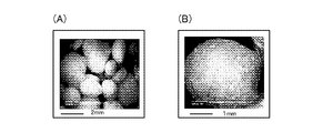
- FIG. 2 is a photograph illustrating the fiber block 1 according to the embodiment of the invention.
- (A) is a photograph in a state where the fiber lumps 1 are gathered
- (B) is an enlarged photograph of one fiber lump 1.
- the fiber lump 1 includes a core portion 3 configured by assembling fibers 2 and a water-permeable membrane 4 that covers the core portion 3. As shown in FIG.
- the core part 3 is granulated in a state where the fibers 2 are gathered in a complicated manner, and is formed in a spherical shape.
- the core part 3 is covered with a water permeable membrane 4, thereby forming a fiber lump 1.
- the fiber lump 1 is configured in a three-dimensional shape close to a sphere, as shown in FIG. 2, for example, a flat rugby ball shape, a confetti shape with protrusions, a polyhedral shape, and a certain amount or more. It is also possible to configure a plate having a thickness or an indefinite shape.
- the form of the fiber 2 used for forming the core part 3 is a long fiber or a short fiber.
- Short fibers also include powdered fibers having a very short fiber length.
- the core portion 3 in which the fibers 2 are gathered is formed.
- a binder such as resin or glue
- a gap 5 is formed between the aggregated fibers 2 inside the core portion 3.
- the fiber lump 1 can retain moisture in the gap 5. Therefore, the state of the voids 5 (for example, the size, number, shape, etc. of the voids 5) relates to the amount of water that can be held by the fiber lump 1, that is, water retention.
- the state of the gap 5 can be adjusted by changing the amount (density) of the fibers 2 used when granulating the core 3, the type, thickness, length, and the like of the fibers 2.
- the size of the fiber 2 is preferably about 5 to 100 ⁇ m in thickness and about 0.5 to 10 mm in length.
- the length of the short fiber is preferably about 0.2 to 0.5 mm.
- hydrophilic fibers As the fiber lump 1, it is preferable to use hydrophilic fibers as the fibers 2 so that the core 3 can sufficiently retain moisture. Thereby, the water retention of the fiber lump 1 can be further increased.
- the type of the fiber 2 may be either natural fiber or synthetic fiber, and is appropriately selected according to the purpose of use of the fiber lump 1.
- Preferable hydrophilic fibers include, for example, natural fibers such as cotton, wool, rayon, and cellulose, and synthetic fibers include vinylon, urethane, nylon, and acetate. Of these fibers, cotton and vinylon are more preferred.
- the core portion 3 is covered with a water permeable membrane 4 on the outer surface.
- the water permeable membrane 4 is a membrane having fine pores through which water can pass. Or it can also be set as the permeable membrane which water
- the water permeable membrane 4 establishes a certain shielding property and rigidity while ensuring water permeability between the core portion 3 of the fiber lump 1 and the external environment.
- “external environment” means an environment outside the fiber lump 1. There can be moisture in the external environment.
- the core part 3 and the external environment are maintained while maintaining the strength and durability of the fiber mass 1 at a certain level or more. It is possible to prevent a rapid movement of moisture between the two and realize appropriate moisture control. Also, the water retention of the fiber lump 1 can be adjusted by changing the film thickness and material of the water permeable membrane 4. Since the water permeable membrane 4 can take in moisture from the external environment and release moisture to the external environment, the fiber lump 1 provided with the water permeable membrane 4 moves moisture such as artificial soil particles. In the accompanying application, it can exhibit excellent adaptability.
- the water permeable membrane 4 forms a thickness from the outer surface portion of the core portion 3 to a state slightly permeated inward so as to reinforce the entangled portions of the fibers 2 constituting the core portion 3 (portions where the fibers 2 contact each other). May be. Thereby, the intensity
- the film thickness of the water-permeable membrane 4 is set to 1 to 500 ⁇ m, preferably 10 to 200 ⁇ m, more preferably 20 to 100 ⁇ m.
- the water permeable membrane 4 has a porous structure in order to ensure sufficient air permeability between the core portion 3 and the external environment.
- the water-permeable membrane 4 is formed with a communication hole 6 that allows the core portion 3 to communicate with the external environment. Since the communication hole 6 has a size larger than the micropores inherent to the water-permeable membrane 4, the communication hole 6 can naturally pass water, and as a result, water permeability between the core portion 3 and the external environment is improved.
- the water-permeable membrane 4 has a porous structure, and the communication holes 6 are directly formed in the water-permeable membrane 4.
- the porous water-permeable membrane 4 such as a natural mineral or a synthetic polymer foam material is used.
- the communicating holes 6 may be formed through a porous filler.
- the diameter of the communication hole 6 formed in the water permeable membrane 4 is set to 1 to 2000 ⁇ m, preferably 10 to 900 ⁇ m, more preferably 300 to 900 ⁇ m.
- the material of the water-permeable membrane 4 is preferably a material that is insoluble in water and hardly oxidized, and examples thereof include a resin material.
- a resin material include polyolefin resins such as polyethylene and polypropylene, vinyl chloride resins such as polyvinyl chloride and polyvinylidene chloride, polyester resins such as polyethylene terephthalate, and styrene resins such as polystyrene. Of these, polyethylene is preferred.
- polymer gelling agents such as polyethylene glycol and acrylamide, natural polysaccharide gelling agents such as alginate and carrageenan, rubber coating agents such as natural rubber and silicone rubber, etc. Is also possible.
- the water retention of the core 3 can be further increased.
- the core part 3 may have a water retention material.
- the fiber lump 1 can be provided with water retention by the water retention material in addition to the water retention by the gap 5 between the fibers 2 that the core portion 3 originally has.
- the water retaining material is added when the core 2 is formed by granulating the fibers 2.
- a method of coating the surface of the fiber 2 with a water retention material is also effective. It is preferable that the water retention material introduced into the core portion 3 by these methods is exposed in the gap 5 of the core portion 3.
- the fiber lump 1 can be suitably used as, for example, a soil improving material added to a dry environment such as a desert because the water retention capacity of the void 5 is greatly improved.
- a polymer water retaining material having water absorption can be used.
- These water retaining materials can be used in combination of two or more.
- porous materials such as ceramics, as a water retention material.
- ⁇ Method for producing fiber lump As a method for producing the fiber lump 1, for example, fibers 2 such as cotton or vinylon are aligned with a carding device or the like, cut to a length of about 3 to 10 mm, and the cut fibers 2 are subjected to rolling granulation and fluidization.
- the core part 3 is formed by granulating into granules by a method such as layer granulation, stirring granulation, compression granulation or extrusion granulation. During granulation, the core portion 3 can be efficiently formed by mixing the fibers 2 with a binder such as resin or glue.
- a binder such as resin or glue.
- the binder either an organic binder or an inorganic binder can be used.
- Organic binders include, for example, synthetic resin binders such as polyolefin binders, polyvinyl alcohol binders, polyurethane binders, polyvinyl acetate binders, polysaccharides such as starch, carrageenan, xanthan gum, gellan gum, alginic acid, and animal properties such as glue. Examples include natural product-based binders such as proteins. Examples of the inorganic binder include silicate binders such as water glass, phosphate binders such as aluminum phosphate, borate binders such as aluminum borate, and hydraulic binders such as cement. An organic binder and an inorganic binder can be used in combination of two or more.
- the core portion 3 can be used without using any binder. Can be formed.
- the granulated core part 3 is transferred to a container, water about half the volume (occupied volume) of the core part 3 is added, and water is immersed in the gap 5 of the core part 3. Further, a polyethylene emulsion of 1/3 to 1/2 of the volume of the core part 3 is added to the core part 3 soaked with water.
- the polyethylene emulsion may be mixed with additives such as pigments, fragrances, bactericides, antibacterial agents, deodorants, and insecticides. Then, the polyethylene emulsion is impregnated from the outer surface portion of the core portion 3 while rolling so that the polyethylene emulsion uniformly adheres to the outer surface portion of the core portion 3.
- the polyethylene emulsion stays in the vicinity of the outer surface portion of the core portion 3.
- the core part 3 to which the polyethylene emulsion is adhered is dried in an oven at 60 to 80 ° C., then the polyethylene is melted at 100 ° C., and the polyethylene is fused to the fibers 2 near the outer surface of the core part 3 to allow water permeability.
- a film 4 is formed.
- the outer surface of the core 3 is covered with the water-permeable membrane 4 of polyethylene, and the fiber lump 1 having strength and durability is completed.
- the solvent contained in the polyethylene emulsion is evaporated, and a porous structure is formed.
- the porous structure functions as a communication hole 6 that communicates the core portion 3 and the external environment.
- the obtained fiber lump 1 is dried and classified as necessary to adjust the particle size.
- the polyethylene emulsion When granulating the core 3, when using short fibers as the fibers 2, the polyethylene emulsion is added in small amounts and granulated while stirring the short fibers with a stirring and mixing granulator. Thereby, the short fibers which form the core part 3 are partially fixed, and the strong core part 3 can be formed. In addition, it is also possible to add water to the short fiber first and granulate, and then add a polyethylene emulsion to finish the core part 3.
- FIG. 3 is an explanatory view schematically showing a state in which a plant is planted in the artificial soil 10 using the fiber block 1 according to the present invention as artificial soil particles.
- the fiber lump 1 forms a certain gap 11 between the fiber lumps 1 in a state of a aggregate structure in which a plurality of fiber lumps 1 are aggregated. Since this gap 11 allows air and water to pass therethrough, excess water can be discharged while holding water necessary for the plant.
- the artificial soil 10 becomes wet, excess water is discharged from the gap 11, and when the artificial soil 10 becomes dry, the surrounding water is sucked up by the capillary phenomenon of the gap 11. it can.
- the artificial soil 10 can drain excess water while securing water necessary for the plant by the gap 11 formed between the adjacent fiber blocks 1, and has excellent air permeability and Drainage is realized. Moreover, since the space
- the particle size of the fiber lump 1 used for the artificial soil 10 is appropriately selected depending on the plant to be cultivated, but is preferably 1 to 10 mm, more preferably 2 to 8 mm, and further preferably 2 to 5 mm. is there. If the particle diameter of the fiber lump 1 is in the above range, an appropriate gap is formed between the fiber lump 1 and good air permeability and drainage can be realized. When the particle size of the fiber lump 1 is less than 1 mm, the size of the gap 11 becomes small, and moisture is excessively held by the capillary force of the gap 11. As a result, it is difficult to absorb oxygen from the plant roots 20 due to a decrease in drainage, and root rot may occur.
- the particle size of the fiber lump 1 is less than 1 mm, the generated particles are not much different from the properties of the fiber itself, which may make it difficult to function as the fiber lump 1.
- the fiber lump 1 has a particle diameter exceeding 10 mm, it is difficult to produce, and even if particles having a particle diameter exceeding 10 mm are obtained, the size of the gap 11 becomes large and the drainage becomes excessive. If it passes, there is a possibility that the plant will hardly absorb sufficient moisture, or the artificial soil 10 becomes sparse and the plant falls over.
- the particle size of the fiber lump 1 can be adjusted by sieving. The particle size of the fiber lump 1 is determined by the following measurement method.
- the fiber mass to be measured is observed with a camera or a microscope together with a scale, and an image thereof is acquired using image processing software (two-dimensional image analysis processing software “WinROOF”, manufactured by Mitani Corporation).
- 100 fiber masses are selected from the image and the outline of the fiber mass is traced.
- the diameter of the equivalent circle is calculated from the circumference of the traced figure.
- the average of the diameters (100 pieces) of the equivalent circles obtained from the respective fiber masses is defined as the average size (unit: pixels).
- the average size is compared with the scale in the image, converted to a unit length ( ⁇ m order to mm order), and the particle size of the fiber block is calculated.
- the size of the fibers 2 constituting the fiber lump 1, the film thickness of the water permeable membrane 4, and the diameter of the communication hole 6 formed in the water permeable membrane 4 are also determined by a measurement method using this image processing.
- the fiber lump 1 Since the fiber lump 1 is coated with the water membrane 4 through the core 3, it achieves excellent water retention and air permeability.
- the fiber lump 1 can adjust the moisture retention amount between a wet state where moisture is held in the core portion 3 in a saturated state and a breathable state where moisture is not held in the core portion 3 in a saturated state. It is.
- the wet state means a state where moisture cannot be retained any more, and for example, a pF value described later is close to 0.
- the air permeable state means a state in which moisture can be retained, for example, a state in which the pF value is about 2 to 7 greater than zero. For example, as shown in FIG.
- the plant root 20 extends into the gap 11 between the adjacent fiber lumps 1 and sucks up the water present in the gap 11 of the artificial soil 10. Since the fiber lump 1 can take in and release moisture, when the external environment is in a dry state, the fiber lump 1 supplies moisture to the plant root 20 through the water-permeable membrane 4 from the core 3 of the fiber lump 1. be able to. That is, at least a part of water is released from the fiber lump 1 to the external environment, and air enters the gap 5 of the fiber lump 1 formed by the release of the water through the communication hole 6. At this time, the capillary root 21 branched from the root 20 of the plant can easily enter the core portion 3 from the communication hole 6 of the fiber lump 1 as shown in FIG.
- the water When water remains inside the fiber lump 1, the water is held in the gap 5 of the core portion 3 and is not easily released from the fiber lump 1 to the external environment, but enters the fiber lump 1.
- the plant capillary root 21 reaches the gap 5 in the core portion 3 and can actively suck up the remaining water retained.
- the artificial soil 10 using the fiber lump 1 can effectively use the water retained in the artificial soil 10, so that the plant witheres or grows poorly without water for a long time. Can be prevented.
- the fiber lump 1 of the present invention has excellent water retention as the artificial soil 10, it can also be applied to the cultivation of leafy vegetables that have been mainly hydroponically cultivated so far.
- the water retention of the artificial soil 10 can be expressed using the pF value as an index.
- the pF value is a common logarithm value of the suction pressure of the soil moisture expressed by the height of the water column, and is a value representing the degree of strength at which the moisture in the soil is attracted by the capillary force of the soil.
- the pF value is 2.0, it corresponds to a pressure of 100 cm of water column (pressure head).
- the pF value is also an index representing the wetness of the soil.
- the pF value becomes low, and the plant root 20 easily absorbs the water.
- the pF value increases, and a large force is required for the plant root 20 to absorb moisture.
- the air is not present in the gaps in the soil, and the state where the water is completely filled with water has a pF value of 0, the soil is 100 ° C. in the heat-dried state, and the state where only water combined with the soil is present. 7
- the pF value at which plants can be cultivated is in the range of 1.5 to 2.7, but in order to grow plants sufficiently, the pF value is in the range of 1.7 to 2.7, Preferably, it is set in the range of 1.7 to 2.3. If the soil has a pF value of 1.7 to 2.7 and the volumetric water content is less than 10 mL / 100 mL (ie, 10% volumetric water content), the amount and timing of watering is difficult, and the soil is always humidified. Or quickly become dry, root rot occurs, and plants are likely to die with water shortage.
- the fiber lump body 1 of the present invention can retain a large amount of water in the core portion 3, it does not dry over a long period of time and can grow plants sufficiently. Even in a situation where the pF value is 1.5 or less, since there are sufficient voids between the fiber blocks 1 and air permeability is secured, roots caused by excessive water consumption such as general soil. It is hard to rot. Even if plenty of watering is done without paying attention to the amount and timing of watering, the soil environment is almost constant. Thereby, not only root vegetables but also leafy vegetables can be cultivated, and the use as the artificial soil 10 is expanded.
- FIG. 4 is a graph illustrating a moisture retention curve of artificial soil using the fiber lump 1 according to the present invention. It shows the relationship between the pressure head (cm H 2 O) and the volumetric water content (%) in the case of using a fibrous mass 1 as an artificial soil particles.
- a fiber mass having a relatively small particle size of 0.75 to 2 mm ( ⁇ ) [b] a fiber mass having a relatively large particle size of 4 mm or more ( ⁇ ), and [c] particles
- ⁇ a fiber mass having a relatively large particle size of 4 mm or more
- the fluctuation range of the volumetric water content is broadened from about 5% to over 30%.
- the water retention amount in the core portion 3 of the fiber lump 1 can be widely adjusted between the “wet state” and the “ventilable state”.
- the comparison of the graphs [a] to [c] suggests that the volume moisture content can be adjusted even with the same pressure head by changing the particle diameter of the fiber block 1.
- the fiber mass is in the range of about 0 to 9% as the volume moisture content.
- the water retention amount (that is, water retention) in the core portion 3 of the body 1 can be adjusted between the “wet state” and the “ventilable state”.
- the fiber lump 1 When the fiber lump 1 is used as artificial soil 10 instead of natural soil, the fiber lump 1 has the ability to retain nitrate nitrogen (NO 3 ⁇ ), K + , Ca 2+ , Mg 2+, etc., which are plant nutrients. It is preferable to provide. If the ability to retain these nutrients is not sufficient, for example, even if chemical fertilizer or the like is supplied to the artificial soil 10, the nutrients flow out due to irrigation or the like, and the plant cannot use the nutrients effectively, resulting in poor growth. There is a fear.
- nitrate nitrogen NO 3 ⁇
- K + K +
- Ca 2+ Ca 2+
- Mg 2+ etc.
- natural soil Since natural soil has the property of taking up cations, it has the ability to retain K + , Ca 2+ , Mg 2+ , and ammonia nitrogen (NH 4+ ), that is, fertilizer. Plants cannot effectively use ammonia nitrogen as a nitrogen source, but because nitrifying bacteria are resident in natural soil, these nitrifying bacteria convert ammonia nitrogen to nitrate nitrogen necessary for plants, Supplying to plants. Therefore, when using the fiber lump 1 as the artificial soil 10 which replaces natural soil, it is necessary to provide the fiber lump 1 with ion exchange ability and to have fertilizer.
- NH 4+ ammonia nitrogen
- the fiber lump 1 contains both ions in order to retain these nutrients. It must have adsorption capacity. Therefore, when forming the fiber lump 1, a cation exchange filler and an anion exchange filler are added, and nitrate nitrogen (NO 3 ⁇ ), K + , Ca 2+ , Mg contained in moisture taken in from the external environment The ions including 2+ can be adsorbed in the fiber lump 1.
- NO 3 ⁇ is a pollutant in rivers and groundwater, but when an anion exchange filler is added to the fiber lump 1, NO 3 ⁇ can be added to the fiber lump 1 even if a large amount of nitrate nitrogen is provided. Since it can be held inside, the outflow to the water environment is suppressed.
- a cation exchange filler and an anion exchange filler to at least one of the gap 5 and the water permeable membrane 4 of the core portion 3.
- the fiber 2 may be granulated by mixing the cation exchange filler and the anion exchange filler and granulating the fiber 2.
- a cation exchange filler and an anion exchange filler may be mixed with the synthetic resin or gelling agent to be coated, and the outer surface portion of the core portion 3 may be coated.
- a cation exchange filler and an anion exchange filler may be added to each of the core part 3 and the water-permeable membrane 4, and a cation exchange filler and an anion exchange filler are separately added to the core part 3 and the water-permeable membrane 4. It may be added.
- Examples of the cation exchange filler include smectite minerals such as montmorillonite, bentonite, beidellite, hectorite, saponite, and stevensite, mica minerals, vermiculite, zeolite, humus, and cation exchange resins.
- Examples of the cation exchange resin include weakly acidic cation exchange resins and strongly acidic cation exchange resins.
- a cation exchange filler used for this embodiment a zeolite or a bentonite is preferable.
- Cation exchange fillers can be used in combination of two or more.
- the cation exchange capacity of the cation exchange filler is generally set to about 5 to 50 meq / 100 g. If the cation exchange capacity is less than 5 meq / 100 g, nutrients cannot be sufficiently taken into the fiber block 1 and the nutrients that have not been taken in may be washed away by irrigation or the like. On the other hand, even if the cation exchange capacity is larger than 50 meq / 100 g, the fertilizer is not greatly improved and it is not economical.
- Anion exchange fillers include, for example, natural layered double hydroxides having a double hydroxide as a main skeleton such as hydrotalcite, manaceite, pyroaulite, sjoglenite, patina, synthetic hydrotalcite and hydrotalcite-like substances And clay minerals such as allophane, imogolite and kaolin, and anion exchange resins.
- the anion exchange resin include weakly basic anion exchange resins and strong basic anion exchange resins.
- hydrotalcite is preferable as the anion exchange filler used in the present embodiment. Two or more anion exchange fillers can be used in combination.
- the anion exchange capacity of the anion exchange filler is generally set to about 5 to 50 meq / 100 g. If the anion exchange capacity is smaller than 5 meq / 100 g, nutrients cannot be sufficiently taken into the fiber block 1 and the nutrients that have not been taken in may be lost due to irrigation or the like. On the other hand, even if the anion exchange capacity is larger than 50 meq / 100 g, the fertilizing power is not greatly improved and it is not economical.
- microorganisms useful for growing plants such as nitrifying bacteria and VA mycorrhizal fungi may be immobilized on the water permeable membrane 4 of the fiber lump 1, and the fiber lump 1 may be used as the artificial soil 10. Thereby, the growth of a plant can be promoted.
- nitrifying bacteria are immobilized on the fiber lump 1, it is possible to give only ammonia nitrogen instead of nitrate nitrogen as nutrients. Thereby, since it is not necessary to use expensive nitrate nitrogen as a fertilizer, the cultivation cost of a plant can be reduced.
- the artificial soil 10 using the fiber lump 1 as artificial soil particles exhibits basic performance (water retention, drainage, air permeability, fertilizer) as a soil even though no natural soil is used. be able to. Therefore, since there is no fear of being polluted by pests and microorganisms, it can be used safely at home or indoors such as a closed plant factory. In closed plant factories, hydroponic cultivation is often performed, and until now it has been difficult to grow root vegetables and plants with high plant height, but artificial soil 10 is the root of a grown plant. 20 can be supported, so that root vegetables and plants with high plant height can be easily cultivated.
- the fiber lump 1 of this embodiment is equipped with a cation exchange filler and an anion exchange filler, cations such as phosphate ions and ammonium ions present in the water environment, nitrate ions, etc. Anion can be removed and the water environment can be improved. Therefore, the fiber lump 1 can be suitably used for water treatment such as waste water treatment.
- the fiber mass of the present invention can be suitably used particularly as artificial soil particles. Therefore, an example of a fiber block assuming artificial soil particles will be described.
- Nine types of fiber aggregates were produced as examples (Examples 1 to 9). Among the nine types of fiber aggregates, the characteristics required for the artificial soil particles were evaluated for the fiber aggregates according to Examples 1 to 3. The evaluation items are eleven items described in “Test / Evaluation Method” described later. The procedure for producing the fiber mass according to Examples 1 to 3 will be described below.
- the characteristics of soil that was not artificial soil (Comparative Examples 1 to 3) were evaluated in the same manner as in Examples 1 to 3. Comparative Examples 1 and 2 are commercially available semi-artificial soils, and Comparative Example 3 is a commercially available natural soil.
- Example 1 Cotton, which is a natural fiber, was used as the fiber constituting the fiber mass. Cotton was aligned with a carding device, cut to a length of about 3 to 10 mm, placed between two rotating plates, and rolled to form a spherical core. About half the volume of water was added to the spherical core, and water was immersed in the fiber. Next, a polyethylene emulsion (Separjon (registered trademark) G315, manufactured by Sumitomo Seika Chemicals Co., Ltd., concentration 40% by weight) is added so as to be half the volume, and impregnated while rolling so that the emulsion uniformly adheres to the outer surface. I let you.
- a polyethylene emulsion Separjon (registered trademark) G315, manufactured by Sumitomo Seika Chemicals Co., Ltd., concentration 40% by weight
- the outer part of the core part is covered with a porous polyethylene water-permeable membrane by melting the polyethylene in the emulsion at 100 ° C. and fusing it to the fiber.
- a fiber mass was produced.
- the particle size of the finished fiber mass was in the range of 1 to 10 mm.
- Example 2 Vinylon short fibers (manufactured by Kuraray Co., Ltd.), which are synthetic fibers, were used as the fibers constituting the fiber mass.
- the vinylon short fiber had a length of 0.5 mm, a fiber diameter of 25 ⁇ m, and an apparent volume of 1000 cc.
- a stirring and mixing granulator manufactured by G-Labo Co., Ltd.
- the polyethylene emulsion used in Example 1 was diluted about 10 times and granulated, and the polyethylene was put inside. A particulate core part impregnated with the emulsion was formed.
- Example 2 the same polyethylene emulsion as used in Example 1 was added so as to be 1 ⁇ 2 of the volume, and impregnated while rolling so that the emulsion adhered uniformly to the outer surface.
- the polyethylene in the emulsion is melted and fused to the fiber at 100 ° C. to fix the vinylon short fibers forming the core part.
- a fiber lump was produced in which the outer surface of the core was coated with a porous polyethylene water-permeable membrane.
- the particle size of the finished fiber mass was in the range of 1 to 10 mm.
- photographed the surface of the fiber lump of a present Example is shown in FIG.
- (A) is a photograph of a part of the surface of the fiber block
- (B) is an enlarged photograph of (A).
- (A) is seen, the whole surface of the core of the fiber block is covered with a water-permeable film of polyethylene, and the region surrounded by an ellipse that appears slightly darker than the surroundings is a communication hole to the core. Yes.
- the fine polyethylene particle aggregates on the surface of the vinylon short fiber which forms a core part, and the water-permeable film is formed. The polyethylene particles are not completely clogged, thereby forming fine pores through which moisture can pass over the entire surface of the water-permeable membrane.
- Example 3 Using an apparent volume of 1000 cc cellulose short fiber (length: 0.2 to 0.3 mm, “Arbocel (registered trademark)” manufactured by Rettenmeier) as a fiber, the same procedure as in Example 2 was performed. A fiber lump whose outer surface was covered with a porous polyethylene water-permeable membrane was prepared. The particle size of the finished fiber mass was in the range of 1-5 mm.
- ⁇ Test and evaluation method> Water retention: Fill the chromatographic tube with the soil to be tested, inject water so that all of the soil is submerged, let stand for 1 hour, drain water from the bottom of the chromatographic tube, and remove from the chromatographic tube for 3 minutes. The amount of water retained when the water no longer falls was measured, and converted into the amount of water retained for 100 cc of the soil to be tested as water retention. The amount of water retained is measured by filling the chromatographic tube with 140 cc of the soil to be tested, adding water from the top, measuring the weight after a predetermined time, and subtracting the weight of the soil to be tested previously measured. did.
- the chromatographic tube is filled with the soil to be tested, and at the time of saturated water content of the soil to be tested, air is flowed from the bottom of the chromatographic tube toward the top at 1 L / min, 0.06 MPa, and the outlet flow was measured for air permeability.
- Suspension growth The number of days until the radish dies without irrigation after the soil to be tested is placed in a 150 cc container with a hole in the lower part, radish 10 days after germination is transplanted after saturation with water (lifetime) Was observed.
- Table 1 summarizes the evaluation results of the fiber aggregates (artificial soil) of Examples 1 to 3 and the commercially available soils of Comparative Examples 1 to 3.
- the artificial soils of Examples 1 to 3 showed higher values in water retention and sprinkling water retention than the semi-artificial soils of Comparative Example 1 and Comparative Example 2.
- the artificial soil of Example 3 had very high measured values of water retention and water retention, and was extremely excellent.
- the water absorption rate which is an advantage of the artificial soil
- the artificial soils of Examples 1 to 3 are superior to the semi-artificial soil of Comparative Example 1
- the artificial soils of Examples 1 and 2 are the semi-artificial soil of Comparative Example 2.
- the result was almost the same.
- the air permeability which is an advantage of the artificial soil, the artificial soils of Examples 1 to 3 had the same results as Comparative Example 1 and Comparative Example 2.
- the artificial soils of Examples 1 to 3 show higher values in water absorption rate and air permeability than the natural soil of Comparative Example 3, and are the same in water retention and water spray retention, which are the advantages of natural soil. More results were shown. Furthermore, the artificial soils of Examples 1 to 3 were superior to Comparative Example 1 in terms of water-stopping growth, and were substantially equivalent to Comparative Examples 2 and 3, so that they are necessary for plants. It was shown that the water retention capacity is high. From these results, the artificial soils of Examples 1 to 3 have both water retention, which is an advantage of natural soil, and air permeability, which is an advantage of semi-artificial soil, and can be suitably used as a substitute for natural soil. It has been shown.
- the artificial soils of Examples 1 to 3 are considered to be suitable for reuse because they have high strength and little change with time. Further, the artificial soils of Examples 1 to 3 are lighter than the soils of Comparative Examples 1 to 3, and especially the artificial soil of Example 3 is extremely light, so that the roof of a building, the veranda of an apartment, etc. Can be suitably used. Furthermore, the artificial soils of Examples 1 to 3 have good replanting workability, almost no dirt in the drainage during watering, white appearance and cleanliness, and can be colored with pigments. It can be suitably used as high indoor artificial soil.
- ⁇ Fiber mass with fertilizer> In the fiber lump of the present invention, if fertilizer can be imparted, fertilizer is added to the fiber lump that originally has high water retention, and artificial soil particles having an excellent balance as soil can be obtained. Therefore, as Examples 4 to 9, fiber aggregates (artificial soil particles) obtained by adding an ion exchange filler to fibers and granulated were produced, and the fertilizer of each fiber aggregate was determined as cation exchange capacity (CEC). As evaluated. In evaluating the cation exchange capacity (CEC), an extract of artificial soil particles was prepared using a general-purpose extraction and filtration device “CEC-10 Ver. 2” manufactured by Fujihira Kogyo Co., Ltd. A sample for volume measurement was used.
- the sample for measuring the cation exchange capacity was subjected to a soil and crop integrated analyzer “SFP-3” manufactured by Fujihira Kogyo Co., Ltd., and the cation exchange capacity (CEC) of the artificial soil particles was measured.
- SFP-3 soil and crop integrated analyzer manufactured by Fujihira Kogyo Co., Ltd.
- CEC cation exchange capacity
- Example 4 An apparent volume of 1000 cc vinylon short fiber (length 0.5 mm, fiber diameter 25 ⁇ m, manufactured by Kuraray Co., Ltd.) was used as the fiber.
- the polyethylene emulsion used in Example 1 was diluted about 10 times while stirring and rolling vinylon short fibers with a stirring and mixing granulator (manufactured by G-Labo Co., Ltd.), and zeolite (Co., Ltd.) as an ion exchange filler.
- Eu-Wil “Ryukyu Light” 100 cc was added and granulated to form a particulate core part impregnated with polyethylene emulsion and supporting zeolite.
- Example 2 the same polyethylene emulsion as used in Example 1 was added so as to be 1 ⁇ 2 of the volume, and impregnated while rolling so that the emulsion adhered uniformly to the outer surface.
- the polyethylene in the emulsion is melted and fused to the fiber at 100 ° C. to fix the vinylon short fibers forming the core part, A fiber lump was produced in which the outer surface of the core was coated with a porous polyethylene water-permeable membrane.
- the particle size of the finished fiber mass was in the range of 1 to 10 mm.
- the cation exchange capacity (CEC) of this fiber mass was 4.1 meq / 100 g.
- Example 5 An apparent volume of 1000 cc vinylon short fiber (length 0.5 mm, fiber diameter 25 ⁇ m, manufactured by Kuraray Co., Ltd.) was used as the fiber. While stirring and rolling the vinylon short fibers with a stirring and mixing granulator (manufactured by G-Labo Co., Ltd.), the polyethylene emulsion used in Example 1 was diluted about 10 times and granulated, and the polyethylene was put inside. A particulate core part impregnated with the emulsion was formed.
- the particle size of the finished fiber mass was in the range of 1 to 10 mm.
- the cation exchange capacity (CEC) of this fiber mass was 2.5 meq / 100 g.
- CEC cation exchange capacity
- Example 6 An apparent volume of 1000 cc vinylon short fiber (length 0.5 mm, fiber diameter 25 ⁇ m, manufactured by Kuraray Co., Ltd.) was used as the fiber.
- the polyethylene emulsion used in Example 1 was diluted about 10 times while stirring and rolling vinylon short fibers with a stirring and mixing granulator (manufactured by G-Labo Co., Ltd.), and zeolite (Co., Ltd.) as an ion exchange filler.
- Eco-Wil “Ryukyu Light” 100 cc was added and granulated to form a particulate core part impregnated with polyethylene emulsion and supporting zeolite.
- Example 7 1000 cc cellulose short fiber (length 0.2-0.3 mm, “Arbocel (registered trademark)” manufactured by Rettenmeier) with an apparent volume was used as the fiber.
- the cellulose emulsion was stirred and rolled with a stirring and mixing granulator (manufactured by G-Labo Co., Ltd.), and the polyethylene emulsion used in Example 1 was diluted about 10 times and zeolite (ion Co., Ltd.) as an ion-exchange filler.
- Eu-Wil “Ryukyu Light” 100 cc was added and granulated to form a particulate core part impregnated with polyethylene emulsion and supporting zeolite.
- Example 2 the same polyethylene emulsion as used in Example 1 was added so as to be 1 ⁇ 2 of the volume, and impregnated while rolling so that the emulsion adhered uniformly to the outer surface.
- the cellulose short fibers forming the core part are fixed by melting polyethylene in the emulsion at 100 ° C. and fusing it to the fibers, A fiber lump was produced in which the outer surface of the core was coated with a porous polyethylene water-permeable membrane.
- the particle size of the finished fiber mass was in the range of 1-5 mm.
- the cation exchange capacity (CEC) of this fiber mass was 4.6 meq / 100 g.
- Example 8 1000 cc cellulose short fiber (length 0.2-0.3 mm, “Arbocel (registered trademark)” manufactured by Rettenmeier) with an apparent volume was used as the fiber. While stirring and rolling cellulose short fibers with a stirring and mixing granulator (manufactured by G-Labo Co., Ltd.), the polyethylene emulsion used in Example 1 was diluted about 10 times and granulated. A particulate core part impregnated with the emulsion was formed.
- Example 9 1000 cc cellulose short fiber (length 0.2-0.3 mm, “Arbocel (registered trademark)” manufactured by Rettenmeier) with an apparent volume was used as the fiber.
- the cellulose emulsion was stirred and rolled with a stirring and mixing granulator (manufactured by G-Labo Co., Ltd.), and the polyethylene emulsion used in Example 1 was diluted about 10 times and zeolite (ion Co., Ltd.) as an ion-exchange filler.
- Eu-Wil “Ryukyu Light” 100 cc was added and granulated to form a particulate core part impregnated with polyethylene emulsion and supporting zeolite.
- the artificial soil particles of Examples 4 to 9 to which the ion exchange filler was added had a cation exchange capacity (CEC) of a certain level or more. Therefore, it is possible to impart fertilizer even with artificial soil particles based on fiber aggregates. In this case, it provides artificial soil with high added value that is excellent in both water retention and fertilizer retention. It becomes possible to do.
- CEC cation exchange capacity
- the artificial soil 10 was shown as an example which uses the fiber lump 1 which concerns on this invention, it is also possible to use the fiber lump 1 for water treatment.
- the fiber lump 1 includes the core portion 3 formed by gathering the fibers 2 and the water-permeable membrane 4 that covers the outer surface portion of the core portion 3, the fiber lump 1 is used for excreta treatment, water treatment of cultured fish, and the like.
- anaerobic microorganisms propagate near the center of the core portion 3, and aerobic microorganisms can efficiently propagate on the water permeable membrane 4.
- the fiber lump according to the present invention and the artificial soil using the fiber lump can be used in kitchen gardens, plant factories, indoor greening, water treatment, manure treatment, and the like.
Abstract
Description
繊維を集合してなるコア部と、
前記コア部を被覆する通水性膜と、
を備えたことにある。 The characteristic configuration of the fiber lump according to the present invention for solving the above problems is as follows.
A core formed by collecting fibers;
A water permeable membrane covering the core portion;
It is in having.
前記通水性膜は、多孔質構造を備えていることが好ましい。 In the fiber mass according to the present invention,
The water permeable membrane preferably has a porous structure.
前記通水性膜は、前記コア部の外表部の40%以上を被覆することが好ましい。 In the fiber mass according to the present invention,
The water-permeable membrane preferably covers 40% or more of the outer surface portion of the core portion.
前記コア部は、保水性材料を有することが好ましい。 In the fiber mass according to the present invention,
The core part preferably has a water retention material.
前記コア部及び前記通水性膜の少なくとも何れか一方にイオン交換能を付与してあることが好ましい。 In the fiber mass according to the present invention,
It is preferable that ion exchange capacity is imparted to at least one of the core part and the water-permeable membrane.
1~10mmの粒径を有することが好ましい。 In the fiber mass according to the present invention,
It preferably has a particle size of 1 to 10 mm.
前記コア部に水分が飽和状態で保持されている湿潤状態と、前記コア部に水分が飽和状態で保持されていない通気可能状態との間で、水分保持量を調整可能に構成されていることが好ましい。 In the fiber mass according to the present invention,
The moisture retention amount is configured to be adjustable between a wet state where moisture is held in the core portion in a saturated state and a breathable state where moisture is not held in the core portion in a saturated state. Is preferred.
前記繊維は、長さが0.2~0.5mmの短繊維であることが好ましい。 In the fiber mass according to the present invention,
The fibers are preferably short fibers having a length of 0.2 to 0.5 mm.
上記何れか一つの繊維塊状体を人工土壌粒子として使用したことにある。 The characteristic configuration of the artificial soil according to the present invention for solving the above problems is as follows.
One of the above-mentioned fiber aggregates is used as artificial soil particles.
図1は、本発明に係る繊維塊状体1を模式的に示した説明図である。(A)は繊維塊状体1の外観図であり、(B)は繊維塊状体1の断面図である。図2は、本発明の実施形態に係る繊維塊状体1を例示する写真である。(A)は繊維塊状体1が集合した状態の写真であり、(B)は一つの繊維塊状体1の拡大写真である。繊維塊状体1は、繊維2を集合して構成したコア部3と、コア部3を被覆する通水性膜4とを備えている。図1に示すように、コア部3は、繊維2が複雑に集合した状態で造粒されたものであり、球状に形成されている。コア部3は通水性膜4で被覆され、これにより繊維塊状体1が構成される。本実施形態では、繊維塊状体1は、図2に示すように、球状に近い立体形状に構成されているが、例えば、扁平したラグビーボール形状、突起を有する金平糖形状、多面体形状、一定以上の厚みを有する板状、不定形状等に構成することも可能である。 <Fiber mass>
FIG. 1 is an explanatory view schematically showing a
繊維塊状体1の製造方法としては、例えば、綿又はビニロン等の繊維2をカーディング装置等で引揃え、3~10mm程度の長さに切断し、切断した繊維2を転動造粒、流動層造粒、攪拌造粒、圧縮造粒、押出造粒等の方法によって粒状に造粒し、コア部3を形成する。造粒の際、繊維2に樹脂や糊等のバインダーを混合すると、コア部3を効率よく形成することができる。バインダーは、有機バインダー又は無機バインダーの何れも使用可能である。有機バインダーは、例えば、ポリオレフィン系バインダー、ポリビニルアルコール系バインダー、ポリウレタン系バインダー、ポリ酢酸ビニル系バインダー等の合成樹脂系バインダー、デンプン、カラギーナン、キサンタンガム、ジェランガム、アルギン酸などの多糖類、膠などの動物性たんぱく質等の天然物系バインダーが挙げられる。無機バインダーは、例えば、水ガラス等のケイ酸系バインダー、リン酸アルミニウム等のリン酸塩系バインダー、ホウ酸アルミニウム等のホウ酸塩系バインダー、セメント等の水硬性バインダーが挙げられる。有機バインダー及び無機バインダーは、二種以上を組み合わせて使用することも可能である。なお、繊維2として絡み易いもの(例えば、屈曲した繊維)を使用する場合、造粒工程を行うだけで繊維2が互いに容易に絡み合うため、この場合は特にバインダーを使用しなくてもコア部3の形成が可能となる。 <Method for producing fiber lump>
As a method for producing the
図3は、本発明に係る繊維塊状体1を人工土壌粒子として使用した人工土壌10に植物を植えた状態を模式的に示した説明図である。図3に示すように、繊維塊状体1は、複数の繊維塊状体1が集合した団粒構造の状態で、繊維塊状体1間に一定の隙間11を形成する。この隙間11は、空気及び水が通過することができるため、植物に必要な水分を保持しながら余分な水分を排出することができる。人工土壌10が湿潤状態となった場合、隙間11から余分な水分を排出し、人工土壌10が乾燥状態となった場合には、隙間11の毛細管現象により、周囲に存在する水分を吸い上げることができる。このように、人工土壌10は、隣接する繊維塊状体1の間に形成される隙間11によって、植物にとって必要な水分を確保しながら、余分な水分を排水することができ、優れた通気性及び排水性を実現している。また、隙間11は、植物の根20が成長するための空間を提供するため、植物の根20が張り易く、ひいては植物の成長を促すことができる。 <Artificial soil using fiber lump>
FIG. 3 is an explanatory view schematically showing a state in which a plant is planted in the
繊維塊状体を構成する繊維として、天然繊維である綿を使用した。綿をカーディング装置で引きそろえ、3~10mm程度の長さに切断して、回転する2枚の板の間に入れて転がして球状のコア部を形成した。球状のコア部に体積の半分程度の水を加えて、繊維中に水を浸み込ませた。次いで、ポリエチレンエマルジョン(セポルジョン(登録商標)G315、住友精化株式会社製、濃度40重量%)を体積の1/2となるように加えて外表部にエマルジョンが均一に付着するように転がしながら含浸させた。エマルジョンが含浸したコア部をオーブンで60℃で乾燥した後、100℃でエマルジョン中のポリエチレンを溶融させて繊維に融着させることにより、コア部の外表部が多孔質ポリエチレンの通水性膜で被覆された繊維塊状体を作製した。出来上がった繊維塊状体の粒径は、1~10mmの範囲内であった。 [Example 1]
Cotton, which is a natural fiber, was used as the fiber constituting the fiber mass. Cotton was aligned with a carding device, cut to a length of about 3 to 10 mm, placed between two rotating plates, and rolled to form a spherical core. About half the volume of water was added to the spherical core, and water was immersed in the fiber. Next, a polyethylene emulsion (Separjon (registered trademark) G315, manufactured by Sumitomo Seika Chemicals Co., Ltd.,
繊維塊状体を構成する繊維として、合成繊維であるビニロン短繊維(株式会社クラレ製)を使用した。ビニロン短繊維は、長さが0.5mm、繊維直径が25μmであり、見かけの容積は1000ccであった。ビニロン短繊維を撹拌混合造粒装置(有限会社G-Labo製)で撹拌、転動させながら実施例1で使用したポリエチレンエマルジョンを約10倍に希釈したものを加えて造粒し、内部にポリエチレンエマルジョンを含浸させた粒子状のコア部を形成した。次いで、実施例1で使用したものと同じポリエチレンエマルジョンを体積の1/2となるように加えて外表部にエマルジョンが均一に付着するように転がしながら含浸させた。エマルジョンが含浸したコア部をオーブンで60℃で乾燥した後、100℃でエマルジョン中のポリエチレンを溶融させて繊維に融着させることにより、コア部を形成するビニロン短繊維同士を固定化し、さらに、コア部の外表部が多孔質ポリエチレンの通水性膜で被覆された繊維塊状体を作製した。出来上がった繊維塊状体の粒径は、1~10mmの範囲内であった。
ここで、本実施例の繊維塊状体の表面を撮影した顕微鏡写真を図5に示す。(A)は繊維塊状体の表面の一部を撮影した写真であり、(B)は(A)の拡大写真である。(A)を見ると、繊維塊状体はコア部の表面全体がポリエチレンの通水性膜で覆われており、周囲より若干暗く写っている楕円で囲った領域がコア部への連通孔となっている。また、(B)を見ると、コア部を形成するビニロン短繊維の表面に微細なポリエチレン粒子が凝集して通水性膜が形成されている。ポリエチレン粒子の間は完全には塞がれておらず、これにより、通水性膜の表面全体に水分が通過可能な微細孔が形成されている。通水性膜の表面に水分が付着すると、その水分は直ちに内部に吸収される。通水性膜の膜厚を大きくした場合でも同様である。このことから、通水性膜の表面には無数の微細孔が存在していることが推認される。 [Example 2]
Vinylon short fibers (manufactured by Kuraray Co., Ltd.), which are synthetic fibers, were used as the fibers constituting the fiber mass. The vinylon short fiber had a length of 0.5 mm, a fiber diameter of 25 μm, and an apparent volume of 1000 cc. While stirring and rolling the vinylon short fibers with a stirring and mixing granulator (manufactured by G-Labo Co., Ltd.), the polyethylene emulsion used in Example 1 was diluted about 10 times and granulated, and the polyethylene was put inside. A particulate core part impregnated with the emulsion was formed. Next, the same polyethylene emulsion as used in Example 1 was added so as to be ½ of the volume, and impregnated while rolling so that the emulsion adhered uniformly to the outer surface. After drying the core part impregnated with the emulsion in an oven at 60 ° C., the polyethylene in the emulsion is melted and fused to the fiber at 100 ° C. to fix the vinylon short fibers forming the core part, A fiber lump was produced in which the outer surface of the core was coated with a porous polyethylene water-permeable membrane. The particle size of the finished fiber mass was in the range of 1 to 10 mm.
Here, the microscope picture which image | photographed the surface of the fiber lump of a present Example is shown in FIG. (A) is a photograph of a part of the surface of the fiber block, and (B) is an enlarged photograph of (A). When (A) is seen, the whole surface of the core of the fiber block is covered with a water-permeable film of polyethylene, and the region surrounded by an ellipse that appears slightly darker than the surroundings is a communication hole to the core. Yes. Moreover, when (B) is seen, the fine polyethylene particle aggregates on the surface of the vinylon short fiber which forms a core part, and the water-permeable film is formed. The polyethylene particles are not completely clogged, thereby forming fine pores through which moisture can pass over the entire surface of the water-permeable membrane. When moisture adheres to the surface of the water permeable membrane, the moisture is immediately absorbed inside. The same applies even when the thickness of the water-permeable membrane is increased. From this, it is presumed that innumerable fine pores exist on the surface of the water-permeable membrane.
見かけの容積で1000ccのセルロース短繊維(長さ0.2~0.3mm、レッテンマイヤー社製「アーボセル(登録商標)」)を繊維として使用し、実施例2と同様の手順により、コア部の外表部が多孔質ポリエチレンの通水性膜で被覆された繊維塊状体を作製した。出来上がった繊維塊状体の粒径は、1~5mmの範囲内であった。 Example 3
Using an apparent volume of 1000 cc cellulose short fiber (length: 0.2 to 0.3 mm, “Arbocel (registered trademark)” manufactured by Rettenmeier) as a fiber, the same procedure as in Example 2 was performed. A fiber lump whose outer surface was covered with a porous polyethylene water-permeable membrane was prepared. The particle size of the finished fiber mass was in the range of 1-5 mm.
(1)保水性:クロマト管に試験対象の土壌を充填し、土壌の全てが水没するように水を注入し、1時間静置後、クロマト管の下部より水を抜き、3分間クロマト管から落水しなくなった時の保水量を測定し、試験対象の土壌100ccに対する保水量に換算して保水性とした。なお、保水量は、クロマト管に試験対象の土壌を140cc充填し、上部から水を加えて所定時間後の重量を測定し、予め測定しておいた試験対象の土壌の重量を差し引くことにより測定した。 <Test and evaluation method>
(1) Water retention: Fill the chromatographic tube with the soil to be tested, inject water so that all of the soil is submerged, let stand for 1 hour, drain water from the bottom of the chromatographic tube, and remove from the chromatographic tube for 3 minutes. The amount of water retained when the water no longer falls was measured, and converted into the amount of water retained for 100 cc of the soil to be tested as water retention. The amount of water retained is measured by filling the chromatographic tube with 140 cc of the soil to be tested, adding water from the top, measuring the weight after a predetermined time, and subtracting the weight of the soil to be tested previously measured. did.

本発明の繊維塊状体において、保肥性を付与することができれば、元々保水性が高い繊維塊状体に保肥性が加わり、土壌としてのバランスに優れた人工土壌粒子とすることができる。そこで、実施例4~9として、繊維にイオン交換性フィラーを添加して造粒した繊維塊状体(人工土壌粒子)を作製し、各繊維塊状体の保肥性を陽イオン交換容量(CEC)として評価した。陽イオン交換容量(CEC)の評価にあたっては、富士平工業株式会社製の汎用抽出・ろ過装置「CEC-10 Ver.2」を用いて人工土壌粒子の抽出液を作製し、これを陽イオン交換容量測定用試料とした。陽イオン交換容量測定用試料を富士平工業株式会社製の土壌・作物体総合分析装置「SFP-3」に供し、人工土壌粒子の陽イオン交換容量(CEC)を測定した。実施例4~9に係る繊維塊状体の作製手順、及び陽イオン交換容量(CEC)の測定結果を以下に説明する。 <Fiber mass with fertilizer>
In the fiber lump of the present invention, if fertilizer can be imparted, fertilizer is added to the fiber lump that originally has high water retention, and artificial soil particles having an excellent balance as soil can be obtained. Therefore, as Examples 4 to 9, fiber aggregates (artificial soil particles) obtained by adding an ion exchange filler to fibers and granulated were produced, and the fertilizer of each fiber aggregate was determined as cation exchange capacity (CEC). As evaluated. In evaluating the cation exchange capacity (CEC), an extract of artificial soil particles was prepared using a general-purpose extraction and filtration device “CEC-10 Ver. 2” manufactured by Fujihira Kogyo Co., Ltd. A sample for volume measurement was used. The sample for measuring the cation exchange capacity was subjected to a soil and crop integrated analyzer “SFP-3” manufactured by Fujihira Kogyo Co., Ltd., and the cation exchange capacity (CEC) of the artificial soil particles was measured. The procedure for producing the fiber mass according to Examples 4 to 9 and the measurement result of the cation exchange capacity (CEC) will be described below.
見かけの容積で1000ccのビニロン短繊維(長さ0.5mm、繊維直径25μm、株式会社クラレ製)を繊維として使用した。ビニロン短繊維を撹拌混合造粒装置(有限会社G-Labo製)で撹拌、転動させながら実施例1で使用したポリエチレンエマルジョンを約10倍に希釈したものと、イオン交換フィラーとしてゼオライト(株式会社エコウィル製「琉球ライト」)100ccとを加えて造粒し、内部にポリエチレンエマルジョンを含浸させるとともにゼオライトを担持させた粒子状のコア部を形成した。次いで、実施例1で使用したものと同じポリエチレンエマルジョンを体積の1/2となるように加えて外表部にエマルジョンが均一に付着するように転がしながら含浸させた。エマルジョンが含浸したコア部をオーブンで60℃で乾燥した後、100℃でエマルジョン中のポリエチレンを溶融させて繊維に融着させることにより、コア部を形成するビニロン短繊維同士を固定化し、さらに、コア部の外表部が多孔質ポリエチレンの通水性膜で被覆された繊維塊状体を作製した。出来上がった繊維塊状体の粒径は、1~10mmの範囲内であった。この繊維塊状体の陽イオン交換容量(CEC)は、4.1meq/100gであった。 Example 4
An apparent volume of 1000 cc vinylon short fiber (length 0.5 mm, fiber diameter 25 μm, manufactured by Kuraray Co., Ltd.) was used as the fiber. The polyethylene emulsion used in Example 1 was diluted about 10 times while stirring and rolling vinylon short fibers with a stirring and mixing granulator (manufactured by G-Labo Co., Ltd.), and zeolite (Co., Ltd.) as an ion exchange filler. (Eco-Wil “Ryukyu Light”) 100 cc was added and granulated to form a particulate core part impregnated with polyethylene emulsion and supporting zeolite. Next, the same polyethylene emulsion as used in Example 1 was added so as to be ½ of the volume, and impregnated while rolling so that the emulsion adhered uniformly to the outer surface. After drying the core part impregnated with the emulsion in an oven at 60 ° C., the polyethylene in the emulsion is melted and fused to the fiber at 100 ° C. to fix the vinylon short fibers forming the core part, A fiber lump was produced in which the outer surface of the core was coated with a porous polyethylene water-permeable membrane. The particle size of the finished fiber mass was in the range of 1 to 10 mm. The cation exchange capacity (CEC) of this fiber mass was 4.1 meq / 100 g.
見かけの容積で1000ccのビニロン短繊維(長さ0.5mm、繊維直径25μm、株式会社クラレ製)を繊維として使用した。ビニロン短繊維を撹拌混合造粒装置(有限会社G-Labo製)で撹拌、転動させながら実施例1で使用したポリエチレンエマルジョンを約10倍に希釈したものを加えて造粒し、内部にポリエチレンエマルジョンを含浸させた粒子状のコア部を形成した。次いで、イオン交換フィラーとしてゼオライト(株式会社エコウィル製「琉球ライト」)30ccと、実施例1で使用したものと同じポリエチレンエマルジョンとを体積の1/2となるように交互に加えて外表部にゼオライトとエマルジョンとが均一に付着するように転がしながら含浸させた。エマルジョンが含浸したコア部をオーブンで60℃で乾燥した後、100℃でエマルジョン中のポリエチレンを溶融させて繊維に融着させることにより、コア部を形成するビニロン短繊維同士を固定化し、さらに、コア部の外表部が多孔質ポリエチレンの通水性膜で被覆された繊維塊状体を作製した。出来上がった繊維塊状体の粒径は、1~10mmの範囲内であった。この繊維塊状体の陽イオン交換容量(CEC)は、2.5meq/100gであった。
なお、この繊維塊状体における間隙のサイズ分布を水銀圧入法で測定したところ、0.1μm~50μmの範囲に亘ってブロードなサイズ分布を有することが確認された。 Example 5
An apparent volume of 1000 cc vinylon short fiber (length 0.5 mm, fiber diameter 25 μm, manufactured by Kuraray Co., Ltd.) was used as the fiber. While stirring and rolling the vinylon short fibers with a stirring and mixing granulator (manufactured by G-Labo Co., Ltd.), the polyethylene emulsion used in Example 1 was diluted about 10 times and granulated, and the polyethylene was put inside. A particulate core part impregnated with the emulsion was formed. Next, 30 cc of zeolite (“Ryukyu Light” manufactured by Ecowill Co., Ltd.) as the ion exchange filler and the same polyethylene emulsion as used in Example 1 were alternately added so that the volume was ½, and the zeolite was added to the outer surface portion. And the emulsion were impregnated while rolling so as to adhere uniformly. After drying the core part impregnated with the emulsion in an oven at 60 ° C., the polyethylene in the emulsion is melted and fused to the fiber at 100 ° C. to fix the vinylon short fibers forming the core part, A fiber lump was produced in which the outer surface of the core was coated with a porous polyethylene water-permeable membrane. The particle size of the finished fiber mass was in the range of 1 to 10 mm. The cation exchange capacity (CEC) of this fiber mass was 2.5 meq / 100 g.
When the size distribution of the gaps in the fiber mass was measured by the mercury intrusion method, it was confirmed that it had a broad size distribution over a range of 0.1 μm to 50 μm.
見かけの容積で1000ccのビニロン短繊維(長さ0.5mm、繊維直径25μm、株式会社クラレ製)を繊維として使用した。ビニロン短繊維を撹拌混合造粒装置(有限会社G-Labo製)で撹拌、転動させながら実施例1で使用したポリエチレンエマルジョンを約10倍に希釈したものと、イオン交換フィラーとしてゼオライト(株式会社エコウィル製「琉球ライト」)100ccとを加えて造粒し、内部にポリエチレンエマルジョンを含浸させるとともにゼオライトを担持させた粒子状のコア部を形成した。次いで、イオン交換フィラーとしてゼオライト(株式会社エコウィル製「琉球ライト」)30ccと、実施例1で使用したものと同じポリエチレンエマルジョンとを体積の1/2となるように交互に加えて外表部にゼオライトとエマルジョンとが均一に付着するように転がしながら含浸させた。エマルジョンが含浸したコア部をオーブンで60℃で乾燥した後、100℃でエマルジョン中のポリエチレンを溶融させて繊維に融着させることにより、コア部を形成するビニロン短繊維同士を固定化し、さらに、コア部の外表部が多孔質ポリエチレンの通水性膜で被覆された繊維塊状体を作製した。出来上がった繊維塊状体の粒径は、1~10mmの範囲内であった。この繊維塊状体の陽イオン交換容量(CEC)は、4.5meq/100gであった。 Example 6
An apparent volume of 1000 cc vinylon short fiber (length 0.5 mm, fiber diameter 25 μm, manufactured by Kuraray Co., Ltd.) was used as the fiber. The polyethylene emulsion used in Example 1 was diluted about 10 times while stirring and rolling vinylon short fibers with a stirring and mixing granulator (manufactured by G-Labo Co., Ltd.), and zeolite (Co., Ltd.) as an ion exchange filler. (Eco-Wil “Ryukyu Light”) 100 cc was added and granulated to form a particulate core part impregnated with polyethylene emulsion and supporting zeolite. Next, 30 cc of zeolite (“Ryukyu Light” manufactured by Ecowill Co., Ltd.) as the ion exchange filler and the same polyethylene emulsion as used in Example 1 were alternately added so that the volume was ½, and the zeolite was added to the outer surface portion. And the emulsion were impregnated while rolling so as to adhere uniformly. After drying the core part impregnated with the emulsion in an oven at 60 ° C., the polyethylene in the emulsion is melted and fused to the fiber at 100 ° C. to fix the vinylon short fibers forming the core part, A fiber lump was produced in which the outer surface of the core was coated with a porous polyethylene water-permeable membrane. The particle size of the finished fiber mass was in the range of 1 to 10 mm. The cation exchange capacity (CEC) of this fiber mass was 4.5 meq / 100 g.
見かけの容積で1000ccのセルロース短繊維(長さ0.2~0.3mm、レッテンマイヤー社製「アーボセル(登録商標)」)を繊維として使用した。セルロース短繊維を撹拌混合造粒装置(有限会社G-Labo製)で撹拌、転動させながら実施例1で使用したポリエチレンエマルジョンを約10倍に希釈したものと、イオン交換フィラーとしてゼオライト(株式会社エコウィル製「琉球ライト」)100ccとを加えて造粒し、内部にポリエチレンエマルジョンを含浸させるとともにゼオライトを担持させた粒子状のコア部を形成した。次いで、実施例1で使用したものと同じポリエチレンエマルジョンを体積の1/2となるように加えて外表部にエマルジョンが均一に付着するように転がしながら含浸させた。エマルジョンが含浸したコア部をオーブンで60℃で乾燥した後、100℃でエマルジョン中のポリエチレンを溶融させて繊維に融着させることにより、コア部を形成するセルロース短繊維同士を固定化し、さらに、コア部の外表部が多孔質ポリエチレンの通水性膜で被覆された繊維塊状体を作製した。出来上がった繊維塊状体の粒径は、1~5mmの範囲内であった。この繊維塊状体の陽イオン交換容量(CEC)は、4.6meq/100gであった。 Example 7
1000 cc cellulose short fiber (length 0.2-0.3 mm, “Arbocel (registered trademark)” manufactured by Rettenmeier) with an apparent volume was used as the fiber. The cellulose emulsion was stirred and rolled with a stirring and mixing granulator (manufactured by G-Labo Co., Ltd.), and the polyethylene emulsion used in Example 1 was diluted about 10 times and zeolite (ion Co., Ltd.) as an ion-exchange filler. (Eco-Wil “Ryukyu Light”) 100 cc was added and granulated to form a particulate core part impregnated with polyethylene emulsion and supporting zeolite. Next, the same polyethylene emulsion as used in Example 1 was added so as to be ½ of the volume, and impregnated while rolling so that the emulsion adhered uniformly to the outer surface. After drying the core part impregnated with the emulsion at 60 ° C. in an oven, the cellulose short fibers forming the core part are fixed by melting polyethylene in the emulsion at 100 ° C. and fusing it to the fibers, A fiber lump was produced in which the outer surface of the core was coated with a porous polyethylene water-permeable membrane. The particle size of the finished fiber mass was in the range of 1-5 mm. The cation exchange capacity (CEC) of this fiber mass was 4.6 meq / 100 g.
見かけの容積で1000ccのセルロース短繊維(長さ0.2~0.3mm、レッテンマイヤー社製「アーボセル(登録商標)」)を繊維として使用した。セルロース短繊維を撹拌混合造粒装置(有限会社G-Labo製)で撹拌、転動させながら実施例1で使用したポリエチレンエマルジョンを約10倍に希釈したものを加えて造粒し、内部にポリエチレンエマルジョンを含浸させた粒子状のコア部を形成した。次いで、イオン交換フィラーとしてゼオライト(株式会社エコウィル製「琉球ライト」)30ccと、実施例1で使用したものと同じポリエチレンエマルジョンとを体積の1/2となるように交互に加えて外表部にゼオライトとエマルジョンとが均一に付着するように転がしながら含浸させた。エマルジョンが含浸したコア部をオーブンで60℃で乾燥した後、100℃でエマルジョン中のポリエチレンを溶融させて繊維に融着させることにより、コア部を形成するセルロース短繊維同士を固定化し、さらに、コア部の外表部が多孔質ポリエチレンの通水性膜で被覆された繊維塊状体を作製した。出来上がった繊維塊状体の粒径は、1~5mmの範囲内であった。この繊維塊状体の陽イオン交換容量(CEC)は、4.8meq/100gであった。 Example 8
1000 cc cellulose short fiber (length 0.2-0.3 mm, “Arbocel (registered trademark)” manufactured by Rettenmeier) with an apparent volume was used as the fiber. While stirring and rolling cellulose short fibers with a stirring and mixing granulator (manufactured by G-Labo Co., Ltd.), the polyethylene emulsion used in Example 1 was diluted about 10 times and granulated. A particulate core part impregnated with the emulsion was formed. Next, 30 cc of zeolite (“Ryukyu Light” manufactured by Ecowill Co., Ltd.) as the ion exchange filler and the same polyethylene emulsion as used in Example 1 were alternately added so that the volume was ½, and the zeolite was added to the outer surface portion. And the emulsion were impregnated while rolling so as to adhere uniformly. After drying the core part impregnated with the emulsion at 60 ° C. in an oven, the cellulose short fibers forming the core part are fixed by melting polyethylene in the emulsion at 100 ° C. and fusing it to the fibers, A fiber lump was produced in which the outer surface of the core was coated with a porous polyethylene water-permeable membrane. The particle size of the finished fiber mass was in the range of 1-5 mm. The cation exchange capacity (CEC) of this fiber mass was 4.8 meq / 100 g.
見かけの容積で1000ccのセルロース短繊維(長さ0.2~0.3mm、レッテンマイヤー社製「アーボセル(登録商標)」)を繊維として使用した。セルロース短繊維を撹拌混合造粒装置(有限会社G-Labo製)で撹拌、転動させながら実施例1で使用したポリエチレンエマルジョンを約10倍に希釈したものと、イオン交換フィラーとしてゼオライト(株式会社エコウィル製「琉球ライト」)100ccとを加えて造粒し、内部にポリエチレンエマルジョンを含浸させるとともにゼオライトを担持させた粒子状のコア部を形成した。次いで、イオン交換フィラーとしてゼオライト(株式会社エコウィル製「琉球ライト」)30ccと、実施例1で使用したものと同じポリエチレンエマルジョンとを体積の1/2となるように交互に加えて外表部にゼオライトとエマルジョンとが均一に付着するように転がしながら含浸させた。エマルジョンが含浸したコア部をオーブンで60℃で乾燥した後、100℃でエマルジョン中のポリエチレンを溶融させて繊維に融着させることにより、コア部を形成するセルロース短繊維同士を固定化し、さらに、コア部の外表部が多孔質ポリエチレンの通水性膜で被覆された繊維塊状体を作製した。出来上がった繊維塊状体の粒径は、1~5mmの範囲内であった。この繊維塊状体の陽イオン交換容量(CEC)は、5.0meq/100gであった。 Example 9
1000 cc cellulose short fiber (length 0.2-0.3 mm, “Arbocel (registered trademark)” manufactured by Rettenmeier) with an apparent volume was used as the fiber. The cellulose emulsion was stirred and rolled with a stirring and mixing granulator (manufactured by G-Labo Co., Ltd.), and the polyethylene emulsion used in Example 1 was diluted about 10 times and zeolite (ion Co., Ltd.) as an ion-exchange filler. (Eco-Wil “Ryukyu Light”) 100 cc was added and granulated to form a particulate core part impregnated with polyethylene emulsion and supporting zeolite. Next, 30 cc of zeolite (“Ryukyu Light” manufactured by Ecowill Co., Ltd.) as the ion exchange filler and the same polyethylene emulsion as used in Example 1 were alternately added so that the volume was ½, and the zeolite was added to the outer surface portion. And the emulsion were impregnated while rolling so as to adhere uniformly. After drying the core part impregnated with the emulsion at 60 ° C. in an oven, the cellulose short fibers forming the core part are fixed by melting polyethylene in the emulsion at 100 ° C. and fusing it to the fibers, A fiber lump was produced in which the outer surface of the core was coated with a porous polyethylene water-permeable membrane. The particle size of the finished fiber mass was in the range of 1-5 mm. The cation exchange capacity (CEC) of this fiber mass was 5.0 meq / 100 g.
上記実施形態では、本発明に係る繊維塊状体1を使用する例として、人工土壌10を示したが、繊維塊状体1を水処理に用いることも可能である。繊維塊状体1は、繊維2を集合してなるコア部3と、コア部3の外表部を被覆する通水性膜4とを備えているため、屎尿処理、養殖魚の水処理等に用いた場合、コア部3の中心付近に嫌気的な微生物が繁殖するとともに、通水性膜4に好気的な微生物が効率的に繁殖することが可能となる。これにより、通水性膜4に繁殖した硝化菌によりアンモニア態窒素を硝酸態窒素に変換し、コア部3の中心付近に繁殖した脱窒菌により硝酸態窒素を窒素ガスに変換して、最終的に窒素ガスを系外に排出することができる。この場合、通水性膜4には、陰イオン交換フィラーを添加するのが好ましい。微生物の細胞膜は負に帯電しているため、陰イオン交換フィラーにより通水性膜4に微生物が吸着して効率的に繁殖し、窒素の処理能力を高めることができる。 <Another embodiment>
In the said embodiment, although the
2 繊維
3 コア部
4 通水性膜
5 空隙
6 連通孔(多孔質構造)
10 人工土壌 DESCRIPTION OF
10 Artificial soil
Claims (9)
- 繊維を集合してなるコア部と、
前記コア部を被覆する通水性膜と、
を備えた繊維塊状体。 A core formed by collecting fibers;
A water permeable membrane covering the core portion;
A fiber mass comprising: - 前記通水性膜は、多孔質構造を備えている請求項1に記載の繊維塊状体。 The fiber mass according to claim 1, wherein the water-permeable membrane has a porous structure.
- 前記通水性膜は、前記コア部の外表部の40%以上を被覆する請求項1又は2に記載の繊維塊状体。 The fiber mass according to claim 1 or 2, wherein the water-permeable membrane covers 40% or more of the outer surface portion of the core portion.
- 前記コア部は、保水性材料を有する請求項1~3の何れか一項に記載の繊維塊状体。 The fiber mass according to any one of claims 1 to 3, wherein the core portion has a water retention material.
- 前記コア部及び前記通水性膜の少なくとも何れか一方にイオン交換能を付与してある請求項1~4の何れか一項に記載の繊維塊状体。 The fiber mass according to any one of claims 1 to 4, wherein ion exchange capacity is imparted to at least one of the core part and the water-permeable membrane.
- 1~10mmの粒径を有する請求項1~5の何れか一項に記載の繊維塊状体。 The fiber mass according to any one of claims 1 to 5, which has a particle diameter of 1 to 10 mm.
- 前記コア部に水分が飽和状態で保持されている湿潤状態と、前記コア部に水分が飽和状態で保持されていない通気可能状態との間で、水分保持量を調整可能に構成されている請求項1~6の何れか一項に記載の繊維塊状体。 The moisture retention amount is configured to be adjustable between a wet state where moisture is held in the core portion in a saturated state and a breathable state where moisture is not held in the core portion in a saturated state. Item 7. The fiber mass according to any one of Items 1 to 6.
- 前記繊維は、長さが0.2~0.5mmの短繊維である請求項1~7の何れか一項に記載の繊維塊状体。 The fiber mass according to any one of claims 1 to 7, wherein the fibers are short fibers having a length of 0.2 to 0.5 mm.
- 請求項1~8の何れか一項に記載の繊維塊状体を人工土壌粒子として使用した人工土壌。 Artificial soil using the fiber mass according to any one of claims 1 to 8 as artificial soil particles.
Priority Applications (6)
| Application Number | Priority Date | Filing Date | Title |
|---|---|---|---|
| EP13840478.5A EP2901848A4 (en) | 2012-09-27 | 2013-09-09 | Massive fiber body, and artificial soil produced using massive fiber body |
| JP2014512972A JP5615461B2 (en) | 2012-09-27 | 2013-09-09 | Artificial soil particles |
| US14/429,590 US20150232391A1 (en) | 2012-09-27 | 2013-09-09 | Fibrous-mass product, and artificial soil using fibrous-mass product |
| CN201380048303.4A CN104640436A (en) | 2012-09-27 | 2013-09-09 | Massive fiber body, and artificial soil produced using massive fiber body |
| KR1020157006378A KR20150042839A (en) | 2012-09-27 | 2013-09-09 | Massive fiber body, and artificial soil produced using massive fiber body |
| PH12015500563A PH12015500563A1 (en) | 2012-09-27 | 2015-03-16 | Fibrous-mass product, and artificial soil using fibrous-mass product |
Applications Claiming Priority (2)
| Application Number | Priority Date | Filing Date | Title |
|---|---|---|---|
| JP2012-213577 | 2012-09-27 | ||
| JP2012213577 | 2012-09-27 |
Publications (1)
| Publication Number | Publication Date |
|---|---|
| WO2014050519A1 true WO2014050519A1 (en) | 2014-04-03 |
Family
ID=50387927
Family Applications (1)
| Application Number | Title | Priority Date | Filing Date |
|---|---|---|---|
| PCT/JP2013/074198 WO2014050519A1 (en) | 2012-09-27 | 2013-09-09 | Massive fiber body, and artificial soil produced using massive fiber body |
Country Status (7)
| Country | Link |
|---|---|
| US (1) | US20150232391A1 (en) |
| EP (1) | EP2901848A4 (en) |
| JP (1) | JP5615461B2 (en) |
| KR (1) | KR20150042839A (en) |
| CN (1) | CN104640436A (en) |
| PH (1) | PH12015500563A1 (en) |
| WO (1) | WO2014050519A1 (en) |
Cited By (2)
| Publication number | Priority date | Publication date | Assignee | Title |
|---|---|---|---|---|
| WO2015159859A1 (en) * | 2014-04-17 | 2015-10-22 | 東洋ゴム工業株式会社 | Production method for artificial soil particles and artificial soil particles |
| WO2016072935A1 (en) * | 2014-11-04 | 2016-05-12 | Nanyang Technological University | Composite bio-granule for a planting medium |
Families Citing this family (10)
| Publication number | Priority date | Publication date | Assignee | Title |
|---|---|---|---|---|
| EP3220735B1 (en) * | 2014-11-19 | 2020-07-22 | University of Wyoming | Vertical hydroponic tower array fixture system |
| US9382166B1 (en) * | 2015-04-14 | 2016-07-05 | Magic Dirt LLC | Plant nutrient composition |
| CN105112059B (en) * | 2015-08-19 | 2019-02-22 | 中国科学院宁波材料技术与工程研究所 | A kind of heavy metal-polluted soil fixative and its preparation method and application |
| JP5875731B1 (en) * | 2015-11-30 | 2016-03-02 | 株式会社大貴 | Manufacturing method of water absorption treatment material |
| JP6173634B1 (en) * | 2017-03-24 | 2017-08-02 | 株式会社大貴 | Excrement treatment material and manufacturing method thereof |
| US11547963B2 (en) | 2017-03-29 | 2023-01-10 | Knowlton Technologies, Llc | High efficiency synthetic filter media |
| CN107235854B (en) * | 2017-07-28 | 2019-11-15 | 贵州芳瑞堂生物科技有限公司 | A kind of extracting method of Theanine in Tea |
| JP2020020517A (en) * | 2018-07-31 | 2020-02-06 | 東洋紡Stc株式会社 | Water-retention compact, air conditioner outdoor unit cooling method, and method for producing water-retention compact |
| CN108865163A (en) * | 2018-08-09 | 2018-11-23 | 姜香 | A kind of preparation method of soil conditioner |
| US10927548B1 (en) | 2020-02-20 | 2021-02-23 | King Saud University | Fiber elements for soil stabilization |
Citations (7)
| Publication number | Priority date | Publication date | Assignee | Title |
|---|---|---|---|---|
| JPH02145133A (en) * | 1988-11-28 | 1990-06-04 | Kureha Chem Ind Co Ltd | Granular material for cultivating plant |
| JPH1132608A (en) * | 1997-07-14 | 1999-02-09 | Maeda Sentan Gijutsu Kenkyusho:Kk | Excrement-treating material for pet and its production |
| JP2003503076A (en) * | 1999-07-06 | 2003-01-28 | ケキラ オイユ | Method for producing substrate for plant growth and block for plant growth |
| JP2004350655A (en) | 2003-05-30 | 2004-12-16 | Sanwa Norin Kk | Plant-cultivating apparatus |
| JP2009273417A (en) * | 2008-05-15 | 2009-11-26 | Michio Ito | Pet excrement disposal material |
| JP2010104383A (en) * | 2010-02-17 | 2010-05-13 | Unicharm Petcare Corp | Method for producing hydrolyzable treating material for animal excrement which can be thrown into toilet |
| JP2010539943A (en) * | 2007-09-28 | 2010-12-24 | ティー.エフ.エイチ.パブリケーションズ、インコーポレーテッド | Biodegradable excreta pad or litter containing nutrients that promote microbial populations |
Family Cites Families (19)
| Publication number | Priority date | Publication date | Assignee | Title |
|---|---|---|---|---|
| BE565392A (en) * | 1900-01-01 | |||
| JPS5556564U (en) * | 1978-10-14 | 1980-04-17 | ||
| LU85256A1 (en) * | 1984-03-19 | 1985-10-14 | Dicalite Europe Nord | POROUS ELEMENT PERMEABLE WITH WATER FOR CULTIVATION OF PLANTS, AS WELL AS METHOD FOR MANUFACTURING THIS ELEMENT |
| US4742086A (en) * | 1985-11-02 | 1988-05-03 | Lion Corporation | Process for manufacturing porous polymer |
| JP2663507B2 (en) * | 1988-05-11 | 1997-10-15 | 東洋紡績株式会社 | Organic fiber granular mass for plant culture |
| JPH0339012A (en) * | 1989-07-04 | 1991-02-20 | Kanebo Ltd | Spherical sphagnum and preparation thereof |
| JPH0367526A (en) * | 1989-08-04 | 1991-03-22 | Toray Ind Inc | Medium for plant culture and production thereof |
| FR2691875B1 (en) * | 1992-06-05 | 1994-09-02 | Saint Gobain Isover | Modular growing media and their domestic use. |
| US5363593A (en) * | 1992-08-12 | 1994-11-15 | Glint Hsh | Synthetic cultivation medium and its method of manufacture |
| KR970011771B1 (en) * | 1994-03-29 | 1997-07-16 | 허경 | Artificial soil composition |
| JPH0833420A (en) * | 1994-05-16 | 1996-02-06 | Toray Ind Inc | Medium for culturing plant and its production |
| JP2000109388A (en) * | 1998-10-05 | 2000-04-18 | Chisso Corp | Coated granular product, agricultural product, cultivating method and soil |
| JP2001204245A (en) * | 2000-01-28 | 2001-07-31 | Yoshihiro Tokashiki | Artificial compound granule and method for producing the same |
| JP2001231359A (en) * | 2000-02-21 | 2001-08-28 | Mg:Kk | Artificial soil body for plant raising |
| JP4495305B2 (en) * | 2000-06-06 | 2010-07-07 | ユニ・チャームペットケア株式会社 | Animal excrement disposal material that can be washed away in the toilet |
| FR2813750B1 (en) * | 2000-09-08 | 2003-06-06 | Tech Etancheite Ct | CUSHIONS AND WATER RETENTION CELLS, METHODS OF MAKING SAME AND APPLICATIONS THEREOF |
| ZA200506336B (en) * | 2003-02-12 | 2006-10-25 | Koch Cellulose Llc | Seedbed for growing vegetation |
| US6946496B2 (en) * | 2003-09-23 | 2005-09-20 | Mankiewicz Paul S | Artificial soil |
| US20060150494A1 (en) * | 2004-12-15 | 2006-07-13 | Masson Norman G | Plant growing media |
-
2013
- 2013-09-09 JP JP2014512972A patent/JP5615461B2/en not_active Expired - Fee Related
- 2013-09-09 US US14/429,590 patent/US20150232391A1/en not_active Abandoned
- 2013-09-09 WO PCT/JP2013/074198 patent/WO2014050519A1/en active Application Filing
- 2013-09-09 CN CN201380048303.4A patent/CN104640436A/en active Pending
- 2013-09-09 EP EP13840478.5A patent/EP2901848A4/en not_active Withdrawn
- 2013-09-09 KR KR1020157006378A patent/KR20150042839A/en not_active Application Discontinuation
-
2015
- 2015-03-16 PH PH12015500563A patent/PH12015500563A1/en unknown
Patent Citations (7)
| Publication number | Priority date | Publication date | Assignee | Title |
|---|---|---|---|---|
| JPH02145133A (en) * | 1988-11-28 | 1990-06-04 | Kureha Chem Ind Co Ltd | Granular material for cultivating plant |
| JPH1132608A (en) * | 1997-07-14 | 1999-02-09 | Maeda Sentan Gijutsu Kenkyusho:Kk | Excrement-treating material for pet and its production |
| JP2003503076A (en) * | 1999-07-06 | 2003-01-28 | ケキラ オイユ | Method for producing substrate for plant growth and block for plant growth |
| JP2004350655A (en) | 2003-05-30 | 2004-12-16 | Sanwa Norin Kk | Plant-cultivating apparatus |
| JP2010539943A (en) * | 2007-09-28 | 2010-12-24 | ティー.エフ.エイチ.パブリケーションズ、インコーポレーテッド | Biodegradable excreta pad or litter containing nutrients that promote microbial populations |
| JP2009273417A (en) * | 2008-05-15 | 2009-11-26 | Michio Ito | Pet excrement disposal material |
| JP2010104383A (en) * | 2010-02-17 | 2010-05-13 | Unicharm Petcare Corp | Method for producing hydrolyzable treating material for animal excrement which can be thrown into toilet |
Non-Patent Citations (1)
| Title |
|---|
| See also references of EP2901848A4 |
Cited By (3)
| Publication number | Priority date | Publication date | Assignee | Title |
|---|---|---|---|---|
| WO2015159859A1 (en) * | 2014-04-17 | 2015-10-22 | 東洋ゴム工業株式会社 | Production method for artificial soil particles and artificial soil particles |
| JPWO2015159859A1 (en) * | 2014-04-17 | 2017-04-13 | 東洋ゴム工業株式会社 | Method for producing artificial soil particles, and artificial soil particles |
| WO2016072935A1 (en) * | 2014-11-04 | 2016-05-12 | Nanyang Technological University | Composite bio-granule for a planting medium |
Also Published As
| Publication number | Publication date |
|---|---|
| CN104640436A (en) | 2015-05-20 |
| EP2901848A4 (en) | 2016-05-18 |
| EP2901848A1 (en) | 2015-08-05 |
| US20150232391A1 (en) | 2015-08-20 |
| PH12015500563A1 (en) | 2015-05-04 |
| JP5615461B2 (en) | 2014-10-29 |
| KR20150042839A (en) | 2015-04-21 |
| JPWO2014050519A1 (en) | 2016-08-22 |
Similar Documents
| Publication | Publication Date | Title |
|---|---|---|
| JP5615461B2 (en) | Artificial soil particles | |
| JP5913452B2 (en) | Artificial soil medium | |
| WO2014050765A1 (en) | Artificial soil particles, artificial soil aggregates, artificial soil molded body, greening sheet, wall greening panel and gardening blocks using artificial soil molded body | |
| US20150313102A1 (en) | Artificial soil aggregate and artificial soil medium | |
| JP6209053B2 (en) | Plant growth medium and plant growth kit | |
| JP6117676B2 (en) | Plant growth medium and plant growth kit | |
| JP2015019653A (en) | Artificial soil particles | |
| WO2015072549A1 (en) | Artificial soil medium | |
| JP2017104019A (en) | Antibacterial fungicidal artificial soil particles and antibacterial fungicidal artificial soil medium | |
| JP6254380B2 (en) | Artificial soil particles and method for producing artificial soil particles | |
| JP6165259B2 (en) | Artificial soil particles and artificial soil medium | |
| JP2017018075A (en) | Solidifying agent for artificial soil culture medium, and method for preparing artificial soil culture medium | |
| JP2016101160A (en) | Artificial soil media adjustment method, and foliage plant cultivation method | |
| JP6034634B2 (en) | Artificial soil molded body, greening sheet, wall greening panel, and gardening block | |
| WO2017110385A1 (en) | Artificial soil medium | |
| JP2016178936A (en) | Artificial soil grain, and manufacturing method of artificial soil grain | |
| JP6218375B2 (en) | Artificial soil particles and artificial soil medium | |
| JP5995674B2 (en) | Artificial soil medium | |
| JP2017176173A (en) | Artificial soil particles, artificial soil medium, and method for producing artificial soil particles | |
| JP2015019652A (en) | Artificial soil particles | |
| JP2015208258A (en) | Artificial soil grains, and artificial soil culture medium | |
| JP2016202083A (en) | Artificial soil particles, and artificial soil culture medium | |
| JP2015195779A (en) | Artificial soil particles and artificial soil culture medium |
Legal Events
| Date | Code | Title | Description |
|---|---|---|---|
| ENP | Entry into the national phase |
Ref document number: 2014512972 Country of ref document: JP Kind code of ref document: A |
|
| 121 | Ep: the epo has been informed by wipo that ep was designated in this application |
Ref document number: 13840478 Country of ref document: EP Kind code of ref document: A1 |
|
| ENP | Entry into the national phase |
Ref document number: 20157006378 Country of ref document: KR Kind code of ref document: A |
|
| WWE | Wipo information: entry into national phase |
Ref document number: 12015500563 Country of ref document: PH |
|
| WWE | Wipo information: entry into national phase |
Ref document number: 14429590 Country of ref document: US |
|
| NENP | Non-entry into the national phase |
Ref country code: DE |
|
| REEP | Request for entry into the european phase |
Ref document number: 2013840478 Country of ref document: EP |
|
| WWE | Wipo information: entry into national phase |
Ref document number: 2013840478 Country of ref document: EP |