WO2014050149A2 - Rechargeable battery accommodating unit - Google Patents
Rechargeable battery accommodating unit Download PDFInfo
- Publication number
- WO2014050149A2 WO2014050149A2 PCT/JP2013/005797 JP2013005797W WO2014050149A2 WO 2014050149 A2 WO2014050149 A2 WO 2014050149A2 JP 2013005797 W JP2013005797 W JP 2013005797W WO 2014050149 A2 WO2014050149 A2 WO 2014050149A2
- Authority
- WO
- WIPO (PCT)
- Prior art keywords
- voltage
- battery
- rechargeable battery
- charge
- accommodating unit
- Prior art date
- Legal status (The legal status is an assumption and is not a legal conclusion. Google has not performed a legal analysis and makes no representation as to the accuracy of the status listed.)
- Ceased
Links
Images
Classifications
-
- H—ELECTRICITY
- H02—GENERATION; CONVERSION OR DISTRIBUTION OF ELECTRIC POWER
- H02J—ELECTRIC POWER NETWORKS; CIRCUIT ARRANGEMENTS OR SYSTEMS FOR SUPPLYING OR DISTRIBUTING ELECTRIC POWER; SYSTEMS FOR STORING ELECTRIC ENERGY
- H02J7/00—Circuit arrangements for charging or discharging batteries or for supplying loads from batteries
- H02J7/60—Circuit arrangements for charging or discharging batteries or for supplying loads from batteries including safety or protection arrangements
- H02J7/663—Circuit arrangements for charging or discharging batteries or for supplying loads from batteries including safety or protection arrangements using battery or load disconnect circuits
-
- H—ELECTRICITY
- H02—GENERATION; CONVERSION OR DISTRIBUTION OF ELECTRIC POWER
- H02J—ELECTRIC POWER NETWORKS; CIRCUIT ARRANGEMENTS OR SYSTEMS FOR SUPPLYING OR DISTRIBUTING ELECTRIC POWER; SYSTEMS FOR STORING ELECTRIC ENERGY
- H02J7/00—Circuit arrangements for charging or discharging batteries or for supplying loads from batteries
- H02J7/02—Circuit arrangements for charging or discharging batteries or for supplying loads from batteries for charging batteries from AC mains by converters
- H02J7/04—Regulation of charging current or voltage
-
- H—ELECTRICITY
- H02—GENERATION; CONVERSION OR DISTRIBUTION OF ELECTRIC POWER
- H02J—ELECTRIC POWER NETWORKS; CIRCUIT ARRANGEMENTS OR SYSTEMS FOR SUPPLYING OR DISTRIBUTING ELECTRIC POWER; SYSTEMS FOR STORING ELECTRIC ENERGY
- H02J7/00—Circuit arrangements for charging or discharging batteries or for supplying loads from batteries
- H02J7/50—Circuit arrangements for charging or discharging batteries or for supplying loads from batteries acting upon multiple batteries simultaneously or sequentially
-
- H—ELECTRICITY
- H02—GENERATION; CONVERSION OR DISTRIBUTION OF ELECTRIC POWER
- H02J—ELECTRIC POWER NETWORKS; CIRCUIT ARRANGEMENTS OR SYSTEMS FOR SUPPLYING OR DISTRIBUTING ELECTRIC POWER; SYSTEMS FOR STORING ELECTRIC ENERGY
- H02J7/00—Circuit arrangements for charging or discharging batteries or for supplying loads from batteries
- H02J7/60—Circuit arrangements for charging or discharging batteries or for supplying loads from batteries including safety or protection arrangements
- H02J7/63—Circuit arrangements for charging or discharging batteries or for supplying loads from batteries including safety or protection arrangements against overdischarge
-
- H—ELECTRICITY
- H02—GENERATION; CONVERSION OR DISTRIBUTION OF ELECTRIC POWER
- H02J—ELECTRIC POWER NETWORKS; CIRCUIT ARRANGEMENTS OR SYSTEMS FOR SUPPLYING OR DISTRIBUTING ELECTRIC POWER; SYSTEMS FOR STORING ELECTRIC ENERGY
- H02J7/00—Circuit arrangements for charging or discharging batteries or for supplying loads from batteries
- H02J7/90—Regulation of charging or discharging current or voltage
- H02J7/94—Regulation of charging or discharging current or voltage in response to battery current
-
- H—ELECTRICITY
- H02—GENERATION; CONVERSION OR DISTRIBUTION OF ELECTRIC POWER
- H02J—ELECTRIC POWER NETWORKS; CIRCUIT ARRANGEMENTS OR SYSTEMS FOR SUPPLYING OR DISTRIBUTING ELECTRIC POWER; SYSTEMS FOR STORING ELECTRIC ENERGY
- H02J7/00—Circuit arrangements for charging or discharging batteries or for supplying loads from batteries
- H02J7/90—Regulation of charging or discharging current or voltage
- H02J7/96—Regulation of charging or discharging current or voltage in response to battery voltage
-
- H—ELECTRICITY
- H02—GENERATION; CONVERSION OR DISTRIBUTION OF ELECTRIC POWER
- H02J—ELECTRIC POWER NETWORKS; CIRCUIT ARRANGEMENTS OR SYSTEMS FOR SUPPLYING OR DISTRIBUTING ELECTRIC POWER; SYSTEMS FOR STORING ELECTRIC ENERGY
- H02J2207/00—Details of circuit arrangements for charging or discharging batteries or supplying loads from batteries
- H02J2207/10—Control circuit supply, e.g. means for supplying power to the control circuit
Definitions
- the invention relates to a rechargeable battery accommodating unit, such as a battery pack, used as a power source of an electrical equipment.
- battery accommodating units are most effective and useful, and in fact have been extensively used in various kinds of electrical equipment.
- Small-size rechargeable battery accommodating units are particularly called as battery packs, and most of the battery packs are shaped to be mountable on or insertable into electrical equipment.
- a backpack type rechargeable battery accommodating unit is relatively large in size as compared with the equipment-mountable type battery packs, and is carried by a strap on one's back or shoulder and is connected to electrical equipment, such as power tool, via a connection cable.
- the backpack type unit generally accommodates a larger number of battery cells than the equipment-mountable type battery pack.
- the backpack type units are high in capacitance and capable of supplying higher power to the applications than the equipment-mountable type battery packs.
- Japanese Patent Application Publication No. 2008-62343 discloses interrupting power from being supplied to a power tool from the battery pack when the voltage of the rechargeable battery has lowered to a lowest limit or when a current flowing in the power tool has exceeded a predetermined criterion.
- a switching element such as an FET, is provided in a path connecting the battery pack and the power tool.
- the switching element may be provided either in the battery pack or in the power tool. In the former case, the switching element is connected between the rechargeable battery and an input/output port of the battery pack.
- the switching element is controlled while monitoring the voltage of the rechargeable battery and a current flowing out from the battery.
- the switching element is normally held OFF and is turned ON when recharging the batter by a battery charger is started or driving the power tool is started.
- the switching element is controlled based on the voltage of the battery.
- An amount of charges stored in the rechargeable batteries gradually decreases due to self-discharge typically caused by a long-term unuse of the battery pack and/or a circuit contained in the battery pack that constantly dissipates power regardless of whether the battery pack is used or not. If the battery pack with a decreased amount of charges is left unused for a long period of time, the voltage from the rechargeable battery would further be lowered to a level incapable of turning on the switching element. Insofar as the switching element cannot be turned on, recharging the battery cannot be carried out and the power tool to which such a battery is connected cannot be driven.
- One possible solution to the above-described problems is to turn on the switching element with the voltage supplied from the battery charger.
- the voltage from the battery charger is output from an auxiliary terminal of the battery charger and applied to the switching element through a special-purpose feeding terminal on the side of the battery pack.
- the above-described solution is not applicable to a battery pack that does not have the special-purpose feeding terminal.
- the proposed solution is not applicable to a two-terminal structure battery pack having only positive and negative terminals to which both the power tool and the battery charger are selectively connected.
- the invention provides a rechargeable battery accommodating unit including a positive terminal and a negative terminal; a rechargeable battery connected between the positive terminal and the negative terminal; connection/disconnection controlling means for selectively connecting the rechargeable battery to and disconnecting the rechargeable battery from the positive terminal; battery voltage detecting means for detecting a battery voltage across the rechargeable battery and outputting a voltage signal indicative of the battery voltage; and control means having an input port for inputting the voltage signal and an output port for outputting a control signal for controlling the connection/disconnection controlling means.
- the control means outputs the control signal to connect the rechargeable battery to the positive terminal only when the voltage signal indicates that the battery voltage is equal to or higher than a first predetermined voltage.
- the first predetermined voltage represents the lowest limit voltage that the rechargeable battery is usable.
- the rechargeable battery accommodating unit may further include voltage lowering means for lowering a charge voltage supplied across the positive terminal and the negative terminal by a battery charger for charging the rechargeable battery in a regular charge mode and outputting a lowered charge voltage lower than the charge voltage.
- the control means controls the connection/disconnection controlling means to disconnect the rechargeable battery from the positive terminal when the voltage signal indicates that the battery voltage is lower than the first predetermined voltage, and charges the rechargeable battery in a precharge mode in which the rechargeable battery is charged with the lowered charge voltage.
- the precharge mode is implemented precedent to a regular charge mode.
- the precharge mode is changed to the regular charge mode when the battery voltage is increased to a second predetermined voltage higher than the first predetermined voltage.
- the battery current detecting means may further be provided for detecting a current flowing in the rechargeable battery.
- the control means determines whether the rechargeable battery is relevant to charge based on at least one of the current detected by the battery current detecting means and the battery voltage detected by the battery voltage detecting means.
- the precharge mode is changed to the regular charge mode, provided that the control means determines that the rechargeable battery is relevant to charge in the regular charge mode.
- the rechargeable battery includes a plurality of cells connected in series.
- the battery voltage detecting means includes cell voltage monitoring means for monitoring a voltage across each of the plurality of cell.
- the control means determines whether the rechargeable battery is relevant to charge based further on results of monitoring by the monitoring means.
- Drive voltage generating means is further provided for generating, based on the charge voltage supplied across the positive terminal and the negative terminal by a battery charger, a drive voltage applied to the control means for placing the control means in an operable condition.
- Another drive voltage generating means is further provided for generating the drive voltage based on the battery voltage.
- Terminal voltage detecting means may further be provided for detecting a voltage developed across the positive terminal and the negative terminal.
- lithium-ion battery as the rechargeable battery is preferred.
- the rechargeable battery accommodating unit according to the invention is advantageous in that the control means can be placed in an operable condition even if the battery voltage is not as high as to generate the drive voltage.
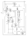
- Fig. 1 is a block diagram showing an electrical arrangement of a battery pack according to one embodiment of the invention.
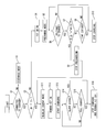
- Fig. 2 is a flowchart illustrating the operation of the battery pack shown in Fig. 1.
- a battery pack will be described as one embodiment of a rechargeable battery accommodating unit according to the invention.
- the battery pack 100 is of a two-terminal structure having positive and negative terminals for connecting to a power tool and a battery charger.
- the positive and negative terminals of the power tool are connected to the positive and negative terminals of the battery pack 100, respectively.
- the battery pack 100 is recharged by the battery charger, the positive and negative terminals of the battery pack 100 are connected to the positive and negative terminals of the battery charger, respectively.
- the battery pack 100 is used as the power source of the power tool, current flows from the positive terminal of the battery pack 100 to the power tool and then returns to the negative terminal of the battery pack 100.
- the battery pack 100 is basically configured from a rechargeable battery 1, a connection/disconnection controlling FET 13 (hereinafter referred simply to as "FET”), a battery voltage detecting circuit 5, and a microcomputer 4.
- FET connection/disconnection controlling FET 13
- the rechargeable battery 1 is connected between the positive and negative terminals of the battery pack 100 across which the battery voltage is developed.
- the rechargeable battery 1 is a lithium-ion battery and made up of a plurality of cells connected in series. In this embodiment, ten lithium-ion battery cells are connected in series. The rated voltage of each lithium-ion battery cell is 3.6V, so that the voltage output from the 10-cell battery 1 is 36V.
- the battery pack 100 according to this embodiment is determined so that the battery 1 accommodated therein is over-discharged when the battery voltage falls below a critical voltage of 30V.
- the expression "low-voltage condition" will be used to refer to a battery condition in which the battery voltage is lower than the critical voltage of 30 volts.
- the battery pack 100 of this embodiment is designed so that when the battery 1 is brought to the low-voltage condition, further use of the battery pack 100 is prohibited. Long-term unused battery packs are likely to become the low-voltage condition.
- the low-voltage condition battery is incapable of turning on the FET 13 with its output voltage.
- the FET 13 serves as a switching element and is provided in a charging path connecting the positive terminal and the battery 1.
- the microcomputer 4 has an output port connected to the FET controlling circuit 14 which in turn is connected to the FET 13.
- the ON/OFF switching of the FET 13 is implemented in response to a control signal output from the FET controlling circuit 14 which is operated in response to an instruction fed from the microcomputer 4.
- the battery voltage detecting circuit 5 is connected between the positive terminal of the battery 1 and ground for detecting the battery voltage.
- the battery voltage detecting circuit 5 is operative when a second switch 12 (to be described later) is OFF.
- the battery voltage detecting circuit 5 is configured from two resistors connected in series. The serially connected resistors are connected between the positive terminal of the battery 1 and ground, and the voltage developed across the ground-side resistor is applied to the microcomputer 4 as a voltage signal indicative of the battery voltage.
- the microcomputer 4 governs the overall operations of the battery pack 100 and has an input port for inputting the voltage signal from the battery voltage detecting circuit 5 and an output port for outputting an instruction signal to the FET controlling circuit 14.
- the FET controlling circuit 14 outputs the control signal to the FET 13 in response to the instruction signal fed from the microcomputer 4.
- the microcomputer 4 and the FET controlling circuit 14 serve as control means.
- the control means has an input port for inputting the voltage signal and an output port for outputting the control signal for controlling the FET 13.
- the control means instructs the FET 13 to connect the battery 1 to the positive terminal of the battery pack 100 only when the voltage signal indicates that the battery voltage is equal to or above a critical voltage, i.e., the lowest voltage level that the battery 1 is allowed to use, which is a criterion for knowing the status of the battery. More specifically, when the battery voltage is equal to or above the critical voltage, the battery is determined to be usable whereas when the battery voltage is lower than the critical voltage, the battery 1 is determined to be in the low-voltage condition.
- a critical voltage i.e., the lowest voltage level that the battery 1 is allowed to use
- the battery pack 100 includes a battery protection IC (integrated circuit) 2, and a protection circuit 3.
- the battery protection IC 3 is connected to the battery 1 to detect the voltage across each of the plurality of cells.
- the output of the battery protection IC 3 is connected to the protection circuit 3 which in turn is connected to the input port of the microcomputer 4.
- the battery protection IC 2 Having detected that the voltage across at least one cell of the battery has fallen below the cell critical voltage (3.0 volts in this embodiment), the battery protection IC 2 outputs a discharge stop signal to the protection circuit 3.
- the protection circuit 3 outputs a first alert signal to the microcomputer 4 advising that further discharge from the battery 1 should be stopped.
- the microcomputer 4 renders the FET 13 OFF through the FET controlling circuit 14 to thereby stop driving the power tool.
- the battery protection IC During charging the battery 1 with a battery charger, the battery protection IC also monitors the voltage across each cell of the battery 1. Having detected that the voltage across at least one cell of the battery 1 has reached or exceeded the highest voltage level or fully charged voltage level, the battery protection IC 2 outputs a charge stop signal to the protection circuit 3. In response to the charge stop signal, the protection circuit 3 outputs a second alert signal to the microcomputer 4 advising that the battery 1 is brought to a fully charged condition or an over-charge condition. Then, the microcomputer 4 renders the FET 13 OFF through the FET controlling circuit 14 to thereby stop charging the battery 1.
- the battery protection IC 2 and the protection circuit 3 serve as cell voltage monitoring means for monitoring a voltage across each of the plurality of cells.
- the microcomputer 4 determines whether the battery 1 is relevant to charge based on the results of monitoring by the monitoring means.
- the microcomputer 4 may determine whether the battery 1 is relevant to charge based on the current flowing in the battery 1 or both the voltage across each of the plurality of cells and the current flowing in the battery 1.
- the battery pack 100 further includes a charge-voltage detecting circuit (terminal voltage detecting means) 6 and a current detecting circuit 7.
- the charge-voltage detecting circuit 6 is connected between the positive terminal and negative terminal (or ground) of the battery pack 100 for detecting the voltage supplied from the battery charger.
- the charge-voltage detecting circuit 6 is also made up of two resistors connected in series, and a voltage developed across the ground-side resistor is applied to the input port of the microcomputer 4.
- the current detecting circuit 7 includes a shunt resistor connected between the negative terminal of the battery pack 100 and the negative terminal of the battery 1 for detecting a current flowing into the battery 1. Although not depicted in Fig. 1, the current detecting circuit 7 further includes an operational amplifier to amplify a voltage developed across the shunt resistor. The current flowing in the shunt resistor is obtained by dividing the voltage across the shunt resistor with the resistance of the shunt resistor. The current thus obtained is applied to the input port of the microcomputer 4.
- a primary drive voltage generating circuit is provided in the circuit of the battery pack 100 for booting and powering the microcomputer 4.
- a drive DC voltage (5 volts in this embodiment) is generated by the primary drive voltage generating circuit based on the battery voltage.
- the primary drive voltage generating circuit is available when the battery 1 is not in the low-voltage condition but is not available when the battery 1 is in the low-voltage condition.
- An auxiliary drive voltage generating circuit is provided for use as a replacement of the primary drive voltage generating circuit.
- the auxiliary drive voltage generating circuit is configured to be operated when the primary drive voltage generating circuit is not available due to the low-voltage condition of the battery 1.
- the auxiliary drive voltage generating circuit also generates the same drive voltage as that generated by the primary drive voltage generating circuit.
- the auxiliary drive voltage generating circuit includes a first voltage dropper 8 and a second voltage dropper 9.
- the first voltage dropper 8 has an input connected to the battery charger via the positive and negative terminals of the battery pack 100, and an output connected to the second voltage dropper 9. It is desirable to employ a switching regulator for the voltage droppers.
- the drive voltage for the microcomputer 4 is generated based either on the battery voltage or on the voltage supplied from the battery charger.
- the battery charger applies a charge voltage relevant to the battery 1, for example, 42 volts for the 10-cell lithium ion battery.
- the voltage from the battery charger is also used for generating the drive voltage for the microcomputer 4. To this effect, the voltage supplied from the battery charger is lowered to, for example, 40 volts by the first voltage dropper 8, and the resultant voltage is further lowered to 5 volts by the second voltage dropper 9.
- the output of the first voltage dropper 8 is also connected to a DC-to-DC converter 11 via a 1 st switch 10.
- the DC-to-DC converter 11 lowers the voltage from the first voltage dropper 8 (40 volts) to a further lowered voltage with which the battery 1 is charged. That is, the battery 1 is charged with a voltage lower than a regular charge voltage of 42 volts.
- the aforementioned second switch 12 is connected between the first voltage dropper 8 and the battery voltage detecting circuit 5.
- the drive voltage (5 volts) is generated based on the voltage supplied from the battery charger to boot the microcomputer 4.
- the microcomputer 4 outputs an instruction signal to the FET controlling circuit 14 instructing to render the FET 13 ON, thereby placing the power tool to be usable.
- the microcomputer 4 is booted regardless of whether the second switch 12 is ON or OFF, as the drive voltage (5V) of the microcomputer 4 is generated based on the voltage from the battery charger.
- a charge control is executed. This determination is made based on the signal from the charge-voltage detecting circuit 6. Specifically, when the voltage output from the charge-voltage detecting circuit 6 is changed from zero volt to any volts greater than zero, then the microcomputer 4 determines that the battery pack 100 is connected to the battery charger.
- the FET 13 is provided in a charging path connecting the battery 1 and the positive terminal of the battery pack 100. Rendering the FET 13 ON connects the battery 1 and the positive terminal whereas rendering the FET 13 OFF disconnects the battery 1 from the positive terminal. Except for the time at which charging and discharging the battery 1 are carried out, the FET 13 is held OFF. As a result, the battery 1 is disconnected from the positive terminal and thus the battery voltage does not appear across the positive and negative terminals of the battery pack 100.
- Enabling or disabling the charging path is controlled by the FET controlling circuit 14 which in turn is controlled by the microcomputer 4. Specifically, the FET 13 is controlled by the microcomputer 4 which has been placed in an operable condition by the voltage supplied from the charger. The FET control is carried out in this way even if the battery voltage is zero.
- the FET 13 is a P-channel FET having a source connected to the positive terminal, and a drain connected to the battery 1.
- a resistor is connected across the source and the gate of the FET 13.
- the FET controlling circuit 14 includes an N-channel FET having a drain connected to the gate of the FET 13 via a resistor.
- the FET configuring the FET controlling circuit 14 has a source held to a low voltage, and a gate connected to the output port of the microcomputer 4.
- Application of a high-level signal to the gate of the FET configuring the FET controlling circuit 14 by the microcomputer 4 renders the FET 13 ON, resulting in connection of the battery 1 to the positive terminal of the battery pack 100.
- FIG. 2 illustrates processes sequentially executed by the microcomputer 4 for charging the battery 1.
- the FET 13 is in an OFF state and thus the charging path is disabled, in which the battery 1 is disconnected from the positive terminal of the battery pack 100.
- the 1 st and 2 nd switches 10 and 12 are normally-open switches and are held OFF.
- the microcomputer 4 determines whether or not the battery pack 100 is connected to the battery charger (S1).
- the battery pack 100 can be connected to the battery charger or the power tool.
- the microcomputer 4 determines that the power tool is connected to the battery pack 100 if determination made in S1 is negative. In such a case, the routine advances to a sub-routine S2 where the battery pack 100 is placed in a discharge mode and the power tool is driven using the battery pack 100 as a power source.
- Determination as to whether the battery pack 100 is connected to the battery charger is made based on the voltage applied to the microcomputer 4 by the charge-voltage detecting circuit 6. More specifically, before the start of charging, the FET 13 is held OFF. The charge voltage (42 volts) supplied from the battery charger is applied to the charge-voltage detecting circuit 6 made up of two resistors connected in series between the positive terminal and ground. A voltage developed across the ground-side resistor is applied to the microcomputer 4, so that the latter recognizes that the battery pack 100 is connected to the battery charger.
- the circuit of the battery pack includes the primary drive voltage generating circuit (not shown) for generating a drive voltage (5 volts) of the microcomputer 4 using the battery 1 as a power source.
- the primary drive voltage generating circuit not shown
- the drive voltage of the microcomputer 4 is generated upon decreasing the voltage supplied from the battery charger with the firsts and second voltage droppers 8 and 9.
- the critical voltage (30 volts), i.e., the lowest limit voltage, is a threshold value (Th) for determining whether the battery 1 is in the low-voltage condition.
- Th a threshold value for determining whether the battery 1 is in the low-voltage condition.
- the battery voltage being lower than 30 volts does not necessarily mean that the battery 1 is actually in the over-discharge condition. However, the battery 1 is treated as being over-discharged if the battery voltage is lower than the critical voltage (30 volts).
- the routine proceeds to S11.
- the microcomputer 4 determines whether the microcomputer 4 receives from the protection circuit 3 the first alert signal.
- the microcomputer 4 determines that the battery 1 is in a condition irrelevant to charge when the microcomputer 4 receives such a signal from the protection circuit 3 (S6: NO). Then, the routine proceeds to S10 where the precharge is stopped.
- the microcomputer 4 does not receive the first alert signal from the protection circuit 3 indicating that the battery 1 is relevant or ready to charge (S6: YES)
- Determination as to whether the battery 1 is relevant or irrelevant to charge may be made based on a rate of change in the battery voltage. Specifically, with the rate of change in the battery voltage being equal to or greater than a prescribed value, the battery 1 is determined to be relevant to charge whereas with the rate of change in the battery voltage being lower than the predetermined value, the battery 1 is determined to be irrelevant to charge.
- precharging the battery 1 is stopped and subsequently a regular charge is carried out (S11).
- the precharge of the battery 1 is continued for a prescribed period of time, e.g., 60 minutes (S9).
- precharging the battery is stopped (S10). In a case where one of the plurality of cells making up of the battery 1 has reached the end of service life or if one of the cells is short-circuited or malfunctioned for other reasons, the battery voltage does not increase despite the battery is continuously precharged.
- the routine proceeds to the regular charge mode (S11).
- charging the battery 1 with the regular charge mode is immediately carried out when the battery voltage detected by the battery voltage detecting circuit 5 is equal to or higher than the critical voltage (30 volts) used as a criterion for determining that the battery 1 is in the low-voltage condition.
- the critical voltage (30 volts) used as a criterion for determining that the battery 1 is in the low-voltage condition.
- precharging the battery is firstly carried out and then charging the battery with the regular charge mode is carried out after confirming that the battery is normal and sound.
- the FET 13 is rendered ON to thereby enable the charging path (S12), that is, to connect the positive terminal of the battery 1 to the positive terminal of the battery pack 100, whereby the normal charging of the battery 1 is started (S13).
- the routine proceeds to S16 where charging the battery 1 is stopped and the FET 13 is rendered OFF. Unless the alert signal is issued from the protection circuit 3 (S14: NO), charging the battery 1 is continued until the battery 1 is brought to a full charge condition (S15). When the battery 1 is determined to be fully charged (S15: YES), charging the battery 1 is stopped and the FET 13 is rendered OFF (S16).
- the two-terminal structure battery pack having only positive and negative terminals is configured to generate a drive voltage of the microcomputer 4 based on the charge voltage supplied from the battery charger.
- the microcomputer can be placed in an operable condition even if the battery contained in the battery pack 100 is in the low-voltage condition in which the battery voltage is too low to generate the drive voltage of the microcomputer 4.
- the FET 13 provided in the charging path connecting the positive terminal of the battery pack 100 and the positive terminal of the battery 1 can be controlled by the microcomputer 4 so as to allow the battery 1 to be charged or stop charging the battery 1.
- the battery 1 can be charged even if the battery 1 is in the low-voltage condition, provided that the battery 1 is not in a fatal condition incapable of being charged, such as batteries which have reached the end of the service life or malfunction batteries.
- the present invention is also applicable to a backpack type power supply, which is generally larger in size than the tool-mountable type battery packs.
- the large-size backpack type power supply has a high voltage output capability and contains high capacity rechargeable battery.
- the backpack type power supply contains X-number cell blocks connected in parallel with one another in which each cell block includes Y-number cells connected in series and corresponding cells in the X-number cell blocks are connected. X and Y are integers equal to or greater than two. It should further be noted that the small-size battery pack and the backpack type power supply are different in how to use.
- the small-size battery packs are used generally by inserting it into or attaching it to a power tool.
- the backpack type power supply is carried by a strap on the user's back and connected to a power tool via an adapter.
- the present invention is also applicable to a shoulder bag type power supply used by carrying it on user's shoulder, a waist belt type power supply that can be worn about the users waist, and a carrybag type power supply (or piggy bag type) carried by the user.
Landscapes
- Engineering & Computer Science (AREA)
- Power Engineering (AREA)
- Charge And Discharge Circuits For Batteries Or The Like (AREA)
- Secondary Cells (AREA)
Abstract
In a microcomputer-controlled rechargeable battery accommodating unit, such as battery pack, of the type having only positive and negative terminals, when the battery voltage is lower than the lowest limit level that the battery is usable, the drive voltage to boot and operate the microcomputer is generated based on the voltage supplied from a battery charger, since the battery voltage is not as high as to generate the drive voltage. Such a low-voltage battery is charged in a precharge mode precedent to a regular charge mode.
Description
The invention relates to a rechargeable battery accommodating unit, such as a battery pack, used as a power source of an electrical equipment.
For every portable power solution, battery accommodating units are most effective and useful, and in fact have been extensively used in various kinds of electrical equipment. Small-size rechargeable battery accommodating units are particularly called as battery packs, and most of the battery packs are shaped to be mountable on or insertable into electrical equipment. A backpack type rechargeable battery accommodating unit is relatively large in size as compared with the equipment-mountable type battery packs, and is carried by a strap on one's back or shoulder and is connected to electrical equipment, such as power tool, via a connection cable.
Recently, lithium-ion batteries are used as the rechargeable batteries, as they are advantageous in high energy density and high current outputting capability. The backpack type unit generally accommodates a larger number of battery cells than the equipment-mountable type battery pack. Thus, the backpack type units are high in capacitance and capable of supplying higher power to the applications than the equipment-mountable type battery packs.
Japanese Patent Application Publication No. 2008-62343 discloses interrupting power from being supplied to a power tool from the battery pack when the voltage of the rechargeable battery has lowered to a lowest limit or when a current flowing in the power tool has exceeded a predetermined criterion. To this effect, a switching element, such as an FET, is provided in a path connecting the battery pack and the power tool. The switching element may be provided either in the battery pack or in the power tool. In the former case, the switching element is connected between the rechargeable battery and an input/output port of the battery pack. The switching element is controlled while monitoring the voltage of the rechargeable battery and a current flowing out from the battery. The switching element is normally held OFF and is turned ON when recharging the batter by a battery charger is started or driving the power tool is started. The switching element is controlled based on the voltage of the battery.
An amount of charges stored in the rechargeable batteries gradually decreases due to self-discharge typically caused by a long-term unuse of the battery pack and/or a circuit contained in the battery pack that constantly dissipates power regardless of whether the battery pack is used or not. If the battery pack with a decreased amount of charges is left unused for a long period of time, the voltage from the rechargeable battery would further be lowered to a level incapable of turning on the switching element. Insofar as the switching element cannot be turned on, recharging the battery cannot be carried out and the power tool to which such a battery is connected cannot be driven.
One possible solution to the above-described problems is to turn on the switching element with the voltage supplied from the battery charger. The voltage from the battery charger is output from an auxiliary terminal of the battery charger and applied to the switching element through a special-purpose feeding terminal on the side of the battery pack. However, since a battery pack exclusively used for a particular power tool has a fixed number of terminals, the above-described solution is not applicable to a battery pack that does not have the special-purpose feeding terminal. For example, the proposed solution is not applicable to a two-terminal structure battery pack having only positive and negative terminals to which both the power tool and the battery charger are selectively connected.
In order to solve the above-noted problems, the invention provides a rechargeable battery accommodating unit including a positive terminal and a negative terminal; a rechargeable battery connected between the positive terminal and the negative terminal; connection/disconnection controlling means for selectively connecting the rechargeable battery to and disconnecting the rechargeable battery from the positive terminal; battery voltage detecting means for detecting a battery voltage across the rechargeable battery and outputting a voltage signal indicative of the battery voltage; and control means having an input port for inputting the voltage signal and an output port for outputting a control signal for controlling the connection/disconnection controlling means. The control means outputs the control signal to connect the rechargeable battery to the positive terminal only when the voltage signal indicates that the battery voltage is equal to or higher than a first predetermined voltage. The first predetermined voltage represents the lowest limit voltage that the rechargeable battery is usable.
The rechargeable battery accommodating unit may further include voltage lowering means for lowering a charge voltage supplied across the positive terminal and the negative terminal by a battery charger for charging the rechargeable battery in a regular charge mode and outputting a lowered charge voltage lower than the charge voltage. The control means controls the connection/disconnection controlling means to disconnect the rechargeable battery from the positive terminal when the voltage signal indicates that the battery voltage is lower than the first predetermined voltage, and charges the rechargeable battery in a precharge mode in which the rechargeable battery is charged with the lowered charge voltage. The precharge mode is implemented precedent to a regular charge mode.
The precharge mode is changed to the regular charge mode when the battery voltage is increased to a second predetermined voltage higher than the first predetermined voltage.
The battery current detecting means may further be provided for detecting a current flowing in the rechargeable battery. The control means determines whether the rechargeable battery is relevant to charge based on at least one of the current detected by the battery current detecting means and the battery voltage detected by the battery voltage detecting means. The precharge mode is changed to the regular charge mode, provided that the control means determines that the rechargeable battery is relevant to charge in the regular charge mode.
The rechargeable battery includes a plurality of cells connected in series. The battery voltage detecting means includes cell voltage monitoring means for monitoring a voltage across each of the plurality of cell. The control means determines whether the rechargeable battery is relevant to charge based further on results of monitoring by the monitoring means.
Drive voltage generating means is further provided for generating, based on the charge voltage supplied across the positive terminal and the negative terminal by a battery charger, a drive voltage applied to the control means for placing the control means in an operable condition. Another drive voltage generating means is further provided for generating the drive voltage based on the battery voltage.
Terminal voltage detecting means may further be provided for detecting a voltage developed across the positive terminal and the negative terminal.
The use of lithium-ion battery as the rechargeable battery is preferred.
The rechargeable battery accommodating unit according to the invention is advantageous in that the control means can be placed in an operable condition even if the battery voltage is not as high as to generate the drive voltage.
In the following description, a battery pack will be described as one embodiment of a rechargeable battery accommodating unit according to the invention.
The battery pack 100 according to this embodiment is of a two-terminal structure having positive and negative terminals for connecting to a power tool and a battery charger. When the battery pack 100 is used as a power source of the power tool, the positive and negative terminals of the power tool are connected to the positive and negative terminals of the battery pack 100, respectively. When the battery pack 100 is recharged by the battery charger, the positive and negative terminals of the battery pack 100 are connected to the positive and negative terminals of the battery charger, respectively. When the battery pack 100 is used as the power source of the power tool, current flows from the positive terminal of the battery pack 100 to the power tool and then returns to the negative terminal of the battery pack 100. On the other hand, when the battery pack 100 is recharged by the battery charger, current flows in the opposite direction, i.e., the current from the battery charger flows into the positive terminal of the battery pack 100 and the current returns to the battery charger from the negative terminal of the battery pack 100.
The battery pack 100 according to the embodiment of the invention is basically configured from a rechargeable battery 1, a connection/disconnection controlling FET 13 (hereinafter referred simply to as "FET"), a battery voltage detecting circuit 5, and a microcomputer 4.
The rechargeable battery 1 is connected between the positive and negative terminals of the battery pack 100 across which the battery voltage is developed. The rechargeable battery 1 is a lithium-ion battery and made up of a plurality of cells connected in series. In this embodiment, ten lithium-ion battery cells are connected in series. The rated voltage of each lithium-ion battery cell is 3.6V, so that the voltage output from the 10-cell battery 1 is 36V. The battery pack 100 according to this embodiment is determined so that the battery 1 accommodated therein is over-discharged when the battery voltage falls below a critical voltage of 30V. In the following description, the expression "low-voltage condition" will be used to refer to a battery condition in which the battery voltage is lower than the critical voltage of 30 volts. The battery pack 100 of this embodiment is designed so that when the battery 1 is brought to the low-voltage condition, further use of the battery pack 100 is prohibited. Long-term unused battery packs are likely to become the low-voltage condition. The low-voltage condition battery is incapable of turning on the FET 13 with its output voltage. In the following description, it is assumed that the battery 1 is in the low-voltage condition, in which the FET 13 cannot be rendered ON irrespective of the control signal applied to the FET 13 from an FET controlling circuit 14. The FET 13 serves as a switching element and is provided in a charging path connecting the positive terminal and the battery 1.
The microcomputer 4 has an output port connected to the FET controlling circuit 14 which in turn is connected to the FET 13. The ON/OFF switching of the FET 13 is implemented in response to a control signal output from the FET controlling circuit 14 which is operated in response to an instruction fed from the microcomputer 4. When the FET 13 is ON, the battery voltage is developed across the positive and negative terminals of the battery pack 100 whereas when the FET 13 is OFF, the batter voltage is not developed thereacross.
The battery voltage detecting circuit 5 is connected between the positive terminal of the battery 1 and ground for detecting the battery voltage. The battery voltage detecting circuit 5 is operative when a second switch 12 (to be described later) is OFF. The battery voltage detecting circuit 5 is configured from two resistors connected in series. The serially connected resistors are connected between the positive terminal of the battery 1 and ground, and the voltage developed across the ground-side resistor is applied to the microcomputer 4 as a voltage signal indicative of the battery voltage.
The microcomputer 4 governs the overall operations of the battery pack 100 and has an input port for inputting the voltage signal from the battery voltage detecting circuit 5 and an output port for outputting an instruction signal to the FET controlling circuit 14. The FET controlling circuit 14 outputs the control signal to the FET 13 in response to the instruction signal fed from the microcomputer 4.
The microcomputer 4 and the FET controlling circuit 14 serve as control means. Specifically, the control means has an input port for inputting the voltage signal and an output port for outputting the control signal for controlling the FET 13. The control means instructs the FET 13 to connect the battery 1 to the positive terminal of the battery pack 100 only when the voltage signal indicates that the battery voltage is equal to or above a critical voltage, i.e., the lowest voltage level that the battery 1 is allowed to use, which is a criterion for knowing the status of the battery. More specifically, when the battery voltage is equal to or above the critical voltage, the battery is determined to be usable whereas when the battery voltage is lower than the critical voltage, the battery 1 is determined to be in the low-voltage condition.
The battery pack 100 includes a battery protection IC (integrated circuit) 2, and a protection circuit 3. The battery protection IC 3 is connected to the battery 1 to detect the voltage across each of the plurality of cells. The output of the battery protection IC 3 is connected to the protection circuit 3 which in turn is connected to the input port of the microcomputer 4. Having detected that the voltage across at least one cell of the battery has fallen below the cell critical voltage (3.0 volts in this embodiment), the battery protection IC 2 outputs a discharge stop signal to the protection circuit 3. In response to the discharge stop signal, the protection circuit 3 outputs a first alert signal to the microcomputer 4 advising that further discharge from the battery 1 should be stopped. Then, the microcomputer 4 renders the FET 13 OFF through the FET controlling circuit 14 to thereby stop driving the power tool.
During charging the battery 1 with a battery charger, the battery protection IC also monitors the voltage across each cell of the battery 1. Having detected that the voltage across at least one cell of the battery 1 has reached or exceeded the highest voltage level or fully charged voltage level, the battery protection IC 2 outputs a charge stop signal to the protection circuit 3. In response to the charge stop signal, the protection circuit 3 outputs a second alert signal to the microcomputer 4 advising that the battery 1 is brought to a fully charged condition or an over-charge condition. Then, the microcomputer 4 renders the FET 13 OFF through the FET controlling circuit 14 to thereby stop charging the battery 1.
As described, the battery protection IC 2 and the protection circuit 3 serve as cell voltage monitoring means for monitoring a voltage across each of the plurality of cells. The microcomputer 4 determines whether the battery 1 is relevant to charge based on the results of monitoring by the monitoring means.
The microcomputer 4 may determine whether the battery 1 is relevant to charge based on the current flowing in the battery 1 or both the voltage across each of the plurality of cells and the current flowing in the battery 1.
The battery pack 100 further includes a charge-voltage detecting circuit (terminal voltage detecting means) 6 and a current detecting circuit 7. The charge-voltage detecting circuit 6 is connected between the positive terminal and negative terminal (or ground) of the battery pack 100 for detecting the voltage supplied from the battery charger. Like the battery voltage detecting circuit 5, the charge-voltage detecting circuit 6 is also made up of two resistors connected in series, and a voltage developed across the ground-side resistor is applied to the input port of the microcomputer 4.
The current detecting circuit 7 includes a shunt resistor connected between the negative terminal of the battery pack 100 and the negative terminal of the battery 1 for detecting a current flowing into the battery 1. Although not depicted in Fig. 1, the current detecting circuit 7 further includes an operational amplifier to amplify a voltage developed across the shunt resistor. The current flowing in the shunt resistor is obtained by dividing the voltage across the shunt resistor with the resistance of the shunt resistor. The current thus obtained is applied to the input port of the microcomputer 4.
Next, a circuit arrangement for powering the microcomputer 4 will be described.
Although not depicted in Fig. 1, a primary drive voltage generating circuit is provided in the circuit of the battery pack 100 for booting and powering the microcomputer 4. A drive DC voltage (5 volts in this embodiment) is generated by the primary drive voltage generating circuit based on the battery voltage. The primary drive voltage generating circuit is available when the battery 1 is not in the low-voltage condition but is not available when the battery 1 is in the low-voltage condition.
An auxiliary drive voltage generating circuit is provided for use as a replacement of the primary drive voltage generating circuit. The auxiliary drive voltage generating circuit is configured to be operated when the primary drive voltage generating circuit is not available due to the low-voltage condition of the battery 1. The auxiliary drive voltage generating circuit also generates the same drive voltage as that generated by the primary drive voltage generating circuit.
The auxiliary drive voltage generating circuit includes a first voltage dropper 8 and a second voltage dropper 9. The first voltage dropper 8 has an input connected to the battery charger via the positive and negative terminals of the battery pack 100, and an output connected to the second voltage dropper 9. It is desirable to employ a switching regulator for the voltage droppers.
As described, the drive voltage for the microcomputer 4 is generated based either on the battery voltage or on the voltage supplied from the battery charger. For the purpose of charging the battery 1, the battery charger applies a charge voltage relevant to the battery 1, for example, 42 volts for the 10-cell lithium ion battery. The voltage from the battery charger is also used for generating the drive voltage for the microcomputer 4. To this effect, the voltage supplied from the battery charger is lowered to, for example, 40 volts by the first voltage dropper 8, and the resultant voltage is further lowered to 5 volts by the second voltage dropper 9.
The output of the first voltage dropper 8 is also connected to a DC-to-DC converter 11 via a 1st switch 10. When the 1st switch 10 is ON, the DC-to-DC converter 11 lowers the voltage from the first voltage dropper 8 (40 volts) to a further lowered voltage with which the battery 1 is charged. That is, the battery 1 is charged with a voltage lower than a regular charge voltage of 42 volts.
The aforementioned second switch 12 is connected between the first voltage dropper 8 and the battery voltage detecting circuit 5. When the second switch 12 is closed, the drive voltage (5 volts) is generated based on the voltage supplied from the battery charger to boot the microcomputer 4. Insofar as no problem exist with the the battery 1, the microcomputer 4 outputs an instruction signal to the FET controlling circuit 14 instructing to render the FET 13 ON, thereby placing the power tool to be usable.
On the other hand, at the time of charging the battery 1, the microcomputer 4 is booted regardless of whether the second switch 12 is ON or OFF, as the drive voltage (5V) of the microcomputer 4 is generated based on the voltage from the battery charger. Upon determining that the battery pack 100 is connected to the battery charger, a charge control is executed. This determination is made based on the signal from the charge-voltage detecting circuit 6. Specifically, when the voltage output from the charge-voltage detecting circuit 6 is changed from zero volt to any volts greater than zero, then the microcomputer 4 determines that the battery pack 100 is connected to the battery charger.
The FET 13 is provided in a charging path connecting the battery 1 and the positive terminal of the battery pack 100. Rendering the FET 13 ON connects the battery 1 and the positive terminal whereas rendering the FET 13 OFF disconnects the battery 1 from the positive terminal. Except for the time at which charging and discharging the battery 1 are carried out, the FET 13 is held OFF. As a result, the battery 1 is disconnected from the positive terminal and thus the battery voltage does not appear across the positive and negative terminals of the battery pack 100. Enabling or disabling the charging path is controlled by the FET controlling circuit 14 which in turn is controlled by the microcomputer 4. Specifically, the FET 13 is controlled by the microcomputer 4 which has been placed in an operable condition by the voltage supplied from the charger. The FET control is carried out in this way even if the battery voltage is zero.
More specifically, the FET 13 is a P-channel FET having a source connected to the positive terminal, and a drain connected to the battery 1. A resistor is connected across the source and the gate of the FET 13. The FET controlling circuit 14 includes an N-channel FET having a drain connected to the gate of the FET 13 via a resistor. The FET configuring the FET controlling circuit 14 has a source held to a low voltage, and a gate connected to the output port of the microcomputer 4. Application of a high-level signal to the gate of the FET configuring the FET controlling circuit 14 by the microcomputer 4 renders the FET 13 ON, resulting in connection of the battery 1 to the positive terminal of the battery pack 100. On the other hand, application of a low-level signal to the gate of the FET configuring the FET controlling circuit 14 by the microcomputer 4 renders the FET 13 OFF, resulting in disconnection of the battery 1 from the positive terminal of the battery pack 100. Insofar as the drive voltage of 5V for driving the microcomputer 4 is being applied to the microcomputer 4, the ON/OFF control of the FET 13 can be implemented.
Next, operation of the battery pack 100 configured as described above will be descried while referring to the flowchart shown in Fig. 2.
The flowchart shown in Fig. 2 illustrates processes sequentially executed by the microcomputer 4 for charging the battery 1.
At the start of series of processes, the FET 13 is in an OFF state and thus the charging path is disabled, in which the battery 1 is disconnected from the positive terminal of the battery pack 100. The 1st and 2nd switches 10 and 12 are normally-open switches and are held OFF.
Initially, the microcomputer 4 determines whether or not the battery pack 100 is connected to the battery charger (S1). The battery pack 100 can be connected to the battery charger or the power tool. The microcomputer 4 determines that the power tool is connected to the battery pack 100 if determination made in S1 is negative. In such a case, the routine advances to a sub-routine S2 where the battery pack 100 is placed in a discharge mode and the power tool is driven using the battery pack 100 as a power source.
Determination as to whether the battery pack 100 is connected to the battery charger is made based on the voltage applied to the microcomputer 4 by the charge-voltage detecting circuit 6. More specifically, before the start of charging, the FET 13 is held OFF. The charge voltage (42 volts) supplied from the battery charger is applied to the charge-voltage detecting circuit 6 made up of two resistors connected in series between the positive terminal and ground. A voltage developed across the ground-side resistor is applied to the microcomputer 4, so that the latter recognizes that the battery pack 100 is connected to the battery charger. On the other hand, when the battery pack 100 is connected to the power tool, no voltage is applied to the charge-voltage detecting circuit 6 from the power tool, so that the voltage applied to the microcomputer 4 by the charge-voltage detecting circuit 6 is zero, thereby enabling the microcomputer 4 to recognize that the battery pack 100 is connected to the power tool or is not connected to the battery charger.
The microcomputer 4 needs to be placed in an operable condition before the microcomputer 4 executes prescribed process. As in the conventional configuration of the battery pack, the circuit of the battery pack according to the above-described embodiment includes the primary drive voltage generating circuit (not shown) for generating a drive voltage (5 volts) of the microcomputer 4 using the battery 1 as a power source. When the battery 1 is in the low-voltage condition, the battery 1 is incapable of driving the microcomputer 4 with the primary drive signal generating circuit. In this embodiment, the drive voltage of the microcomputer 4 is generated upon decreasing the voltage supplied from the battery charger with the firsts and second voltage droppers 8 and 9.
Next, determination is made in S3 as to whether or not the battery voltage (BV) is equal to or higher than 30 volts that is the critical voltage of the battery 1 (S3). As described previously, the critical voltage (30 volts), i.e., the lowest limit voltage, is a threshold value (Th) for determining whether the battery 1 is in the low-voltage condition. It should be noted that the battery voltage being lower than 30 volts does not necessarily mean that the battery 1 is actually in the over-discharge condition. However, the battery 1 is treated as being over-discharged if the battery voltage is lower than the critical voltage (30 volts). When determination is made such that the battery voltage is equal to or higher than 30 volts (S3: YES), the routine proceeds to S11. On the other hand, when determination is made such that the battery voltage is lower than 30 volts (S3: NO), the routine proceeds to S4. Determination as to whether the battery voltage is equal to or higher than 30 volts is made based on the output voltage from the battery voltage detecting circuit 5.
The fact that the battery voltage is lower than 30 volts (S3: NO) indicates that the battery 1 is in the low-voltage condition. If it is the case, the microcomputer 4 outputs a high level signal to the 1st switch 10 to render the latter ON (S4), whereupon the routine proceeds to a precharge mode for precharging the low-voltage battery 1, in which the battery 1 is charged with a voltage lower than a regular charge voltage (S5).
Next, it is determined whether the microcomputer 4 receives from the protection circuit 3 the first alert signal. The microcomputer 4 determines that the battery 1 is in a condition irrelevant to charge when the microcomputer 4 receives such a signal from the protection circuit 3 (S6: NO). Then, the routine proceeds to S10 where the precharge is stopped. On the other hand, when the microcomputer 4 does not receive the first alert signal from the protection circuit 3 indicating that the battery 1 is relevant or ready to charge (S6: YES), it is further determined that the battery voltage has reached or exceeded a predetermined value "a" volts, e.g., 30 volts (S7).
Determination as to whether the battery 1 is relevant or irrelevant to charge may be made based on a rate of change in the battery voltage. Specifically, with the rate of change in the battery voltage being equal to or greater than a prescribed value, the battery 1 is determined to be relevant to charge whereas with the rate of change in the battery voltage being lower than the predetermined value, the battery 1 is determined to be irrelevant to charge.
If the battery voltage has reached or exceeded the predetermined value (30 volts) (S7: YES), precharging the battery 1 is stopped and subsequently a regular charge is carried out (S11). On the other hand, if the battery voltage has not yet reached the predetermined value (S7: NO), the precharge of the battery 1 is continued for a prescribed period of time, e.g., 60 minutes (S9). When the battery voltage does not reach the predetermined voltage ("a" volts) during prescribed period of time(S9: YES), precharging the battery is stopped (S10). In a case where one of the plurality of cells making up of the battery 1 has reached the end of service life or if one of the cells is short-circuited or malfunctioned for other reasons, the battery voltage does not increase despite the battery is continuously precharged.
When the battery 1 is determined to be normal and sound in the precharge mode and when the battery voltage has reached or exceeded 30 volts, the routine proceeds to the regular charge mode (S11). As described, according to this embodiment, charging the battery 1 with the regular charge mode is immediately carried out when the battery voltage detected by the battery voltage detecting circuit 5 is equal to or higher than the critical voltage (30 volts) used as a criterion for determining that the battery 1 is in the low-voltage condition. When the battery 1 is in the low-voltage condition, precharging the battery is firstly carried out and then charging the battery with the regular charge mode is carried out after confirming that the battery is normal and sound. In the regular charge mode, the FET 13 is rendered ON to thereby enable the charging path (S12), that is, to connect the positive terminal of the battery 1 to the positive terminal of the battery pack 100, whereby the normal charging of the battery 1 is started (S13).
When the first alert signal is received from the protection circuit 3 (S14: YES), the routine proceeds to S16 where charging the battery 1 is stopped and the FET 13 is rendered OFF. Unless the alert signal is issued from the protection circuit 3 (S14: NO), charging the battery 1 is continued until the battery 1 is brought to a full charge condition (S15). When the battery 1 is determined to be fully charged (S15: YES), charging the battery 1 is stopped and the FET 13 is rendered OFF (S16).
As described above, the two-terminal structure battery pack having only positive and negative terminals is configured to generate a drive voltage of the microcomputer 4 based on the charge voltage supplied from the battery charger. As such, the microcomputer can be placed in an operable condition even if the battery contained in the battery pack 100 is in the low-voltage condition in which the battery voltage is too low to generate the drive voltage of the microcomputer 4. Once the microcomputer 4 is placed in the operable condition, the FET 13 provided in the charging path connecting the positive terminal of the battery pack 100 and the positive terminal of the battery 1 can be controlled by the microcomputer 4 so as to allow the battery 1 to be charged or stop charging the battery 1. Thus, the battery 1 can be charged even if the battery 1 is in the low-voltage condition, provided that the battery 1 is not in a fatal condition incapable of being charged, such as batteries which have reached the end of the service life or malfunction batteries.
While description has been made with respect to a battery pack as one example of rechargeable battery accommodating units, the present invention is also applicable to a backpack type power supply, which is generally larger in size than the tool-mountable type battery packs. It should be noted that unlike the small-size battery pack, the large-size backpack type power supply has a high voltage output capability and contains high capacity rechargeable battery. Typically, the backpack type power supply contains X-number cell blocks connected in parallel with one another in which each cell block includes Y-number cells connected in series and corresponding cells in the X-number cell blocks are connected. X and Y are integers equal to or greater than two. It should further be noted that the small-size battery pack and the backpack type power supply are different in how to use. Specifically, the small-size battery packs are used generally by inserting it into or attaching it to a power tool. The backpack type power supply is carried by a strap on the user's back and connected to a power tool via an adapter. The present invention is also applicable to a shoulder bag type power supply used by carrying it on user's shoulder, a waist belt type power supply that can be worn about the users waist, and a carrybag type power supply (or piggy bag type) carried by the user.
While the present invention has been described with reference to a specific embodiment, it would be apparent for a person skilled in the art that a variety of various changes and modifications may be made without departing from the scope of the invention.
1 Rechargeable battery
2 Battery protection IC
3 Protection circuit
4 Microcomputer
5 Battery voltage detecting circuit
6 Charge-voltage detecting circuit
7 Current detecting circuit
8 1st Voltage dropper
9 2nd Voltage dropper
10 1st Switch
11 DC-to-DC converter
12 2nd Switch
13 Connection/disconnection control FET
14 FET controlling circuit
100 Battery pack
2 Battery protection IC
3 Protection circuit
4 Microcomputer
5 Battery voltage detecting circuit
6 Charge-voltage detecting circuit
7 Current detecting circuit
8 1st Voltage dropper
9 2nd Voltage dropper
10 1st Switch
11 DC-to-DC converter
12 2nd Switch
13 Connection/disconnection control FET
14 FET controlling circuit
100 Battery pack
Claims (10)
- A rechargeable battery accommodating unit comprising:
a positive terminal and a negative terminal;
a rechargeable battery connected between the positive terminal and the negative terminal;
connection/disconnection controlling means for selectively connecting the rechargeable battery to and disconnecting the rechargeable battery from the positive terminal;
battery voltage detecting means for detecting a battery voltage across the rechargeable battery and outputting a voltage signal indicative of the battery voltage; and
control means having an input port for inputting the voltage signal and an output port for outputting a control signal for controlling the connection/disconnection controlling means,
characterized in that the control means outputs the control signal to connect the rechargeable battery to the positive terminal only when the voltage signal indicates that the battery voltage is equal to or higher than a first predetermined voltage, the first predetermined voltage being a lowest limit voltage that the rechargeable battery is usable. - The rechargeable battery accommodating unit according to claim 1, characterized in that voltage lowering means is further provided for lowering a charge voltage supplied across the positive terminal and the negative terminal by a battery charger for charging the rechargeable battery in a regular charge mode and outputting a lowered charge voltage lower than the charge voltage, and
that the control means controls the connection/disconnection controlling means to disconnect the rechargeable battery from the positive terminal when the voltage signal indicates that the battery voltage is lower than the first predetermined voltage, and charges the rechargeable battery in a precharge mode in which the rechargeable battery is charged with the lowered charge voltage, the precharge mode being implemented precedent to a regular charge mode. - The rechargeable battery accommodating unit according to claim 2, characterized in that the precharge mode is changed to the regular charge mode when the battery voltage is increased to a second predetermined voltage higher than the first predetermined voltage.
- The rechargeable battery accommodating unit according to any one of claims 1 to 3, characterized in that battery current detecting means is further provided for detecting a current flowing in the rechargeable battery.
- The rechargeable battery accommodating unit according to claim 4, characterized in that the control means determines whether the rechargeable battery is relevant to charge based on at least one of the current detected by the battery current detecting means and the battery voltage detected by the battery voltage detecting means.
- The rechargeable battery accommodating unit according to claim 5, characterized in that the precharge mode is changed to the regular charge mode, provided that the control means determines that the rechargeable battery is relevant to charge in the regular charge mode.
- The rechargeable battery accommodating unit according to claim 6, characterized in that the rechargeable battery includes a plurality of cells connected in series, the battery voltage detecting means includes cell voltage monitoring means for monitoring a voltage across each of the plurality of cells, and the control means determines whether the rechargeable battery is relevant to charge based further on results of monitoring by the monitoring means.
- The rechargeable battery accommodating unit according to claim 1, characterized in that drive voltage generating means is further provided for generating, based on the charge voltage supplied across the positive terminal and the negative terminal by a battery charger, a drive voltage applied to the control means for placing the control means in an operable condition.
- The rechargeable battery accommodating unit according to claim 1, characterized in that terminal voltage detecting means is further provided for detecting a voltage developed across the positive terminal and the negative terminal.
- The rechargeable battery accommodating unit according to claim 1, characterized in that the rechargeable battery is lithium-ion battery.
Applications Claiming Priority (2)
| Application Number | Priority Date | Filing Date | Title |
|---|---|---|---|
| JP2012-218499 | 2012-09-28 | ||
| JP2012218499A JP2014073021A (en) | 2012-09-28 | 2012-09-28 | Secondary battery housing body |
Publications (2)
| Publication Number | Publication Date |
|---|---|
| WO2014050149A2 true WO2014050149A2 (en) | 2014-04-03 |
| WO2014050149A3 WO2014050149A3 (en) | 2014-08-28 |
Family
ID=49385319
Family Applications (1)
| Application Number | Title | Priority Date | Filing Date |
|---|---|---|---|
| PCT/JP2013/005797 Ceased WO2014050149A2 (en) | 2012-09-28 | 2013-09-27 | Rechargeable battery accommodating unit |
Country Status (2)
| Country | Link |
|---|---|
| JP (1) | JP2014073021A (en) |
| WO (1) | WO2014050149A2 (en) |
Families Citing this family (1)
| Publication number | Priority date | Publication date | Assignee | Title |
|---|---|---|---|---|
| AU2024279066A1 (en) * | 2023-06-01 | 2025-12-18 | Palmer Energy Technology Limited | Battery management system and method with auxiliary power source |
Citations (1)
| Publication number | Priority date | Publication date | Assignee | Title |
|---|---|---|---|---|
| JP2008062343A (en) | 2006-09-07 | 2008-03-21 | Hitachi Koki Co Ltd | Electric tool |
Family Cites Families (7)
| Publication number | Priority date | Publication date | Assignee | Title |
|---|---|---|---|---|
| US7589499B2 (en) * | 2004-03-25 | 2009-09-15 | O2Micro International Limited | Over voltage transient controller |
| JP2006331953A (en) * | 2005-05-27 | 2006-12-07 | Mitsumi Electric Co Ltd | Battery protection method and battery protection circuit |
| US7750604B2 (en) * | 2007-02-16 | 2010-07-06 | O2Micro, Inc. | Circuits and methods for battery charging |
| JP5217468B2 (en) * | 2008-02-01 | 2013-06-19 | 株式会社リコー | Secondary battery protecting semiconductor device, battery pack using the secondary battery protecting semiconductor device, and electronic apparatus using the battery pack |
| US8405358B2 (en) * | 2008-09-02 | 2013-03-26 | O2Micro Inc. | Battery charging systems with controllable charging currents |
| US8044640B2 (en) * | 2008-10-07 | 2011-10-25 | Black & Decker Inc. | Method for stepping current output by a battery charger |
| US8698458B2 (en) * | 2010-07-08 | 2014-04-15 | Samsung Sdi Co., Ltd. | Battery pack having boosting charge function and method thereof |
-
2012
- 2012-09-28 JP JP2012218499A patent/JP2014073021A/en active Pending
-
2013
- 2013-09-27 WO PCT/JP2013/005797 patent/WO2014050149A2/en not_active Ceased
Patent Citations (1)
| Publication number | Priority date | Publication date | Assignee | Title |
|---|---|---|---|---|
| JP2008062343A (en) | 2006-09-07 | 2008-03-21 | Hitachi Koki Co Ltd | Electric tool |
Also Published As
| Publication number | Publication date |
|---|---|
| WO2014050149A3 (en) | 2014-08-28 |
| JP2014073021A (en) | 2014-04-21 |
Similar Documents
| Publication | Publication Date | Title |
|---|---|---|
| CN101432944B (en) | Deep under voltage recovery in a battery pack | |
| JP5067722B2 (en) | Electric tool | |
| US10199844B2 (en) | Power-supplying device | |
| KR100297608B1 (en) | Charging control device, charging-and-discharging device and electronic equipment including the same | |
| CN100442630C (en) | Rechargeable battery packs for power tools | |
| JP2021517448A (en) | Balancing device, battery management system including it and battery pack | |
| CN101183794A (en) | Battery | |
| BRPI0600115B1 (en) | SYSTEMS AND METHODS FOR REGULATING PRE-LOAD CURRENT ON A BATTERY SYSTEM | |
| JP2015050833A (en) | Battery pack, electric tool equipped with the battery pack, and charger | |
| KR102472906B1 (en) | Battery Pack and Electric Vehicle Including The Same | |
| JP6589948B2 (en) | Power supply | |
| CN108336777A (en) | Power supply module with lithium-ion capacitor | |
| US6429626B1 (en) | Battery pack | |
| KR101863092B1 (en) | Method for controlling battery charging and battery pack being applied the method | |
| JP2001339867A (en) | Electric apparatus with built-in battery and motor | |
| WO2014050149A2 (en) | Rechargeable battery accommodating unit | |
| KR102785018B1 (en) | Secondary battery protection circuit, battery pack, battery system and method for protecting secondary battery | |
| US20040251877A1 (en) | Voltage adapter circuit for a lithium ion rechargeable battery | |
| KR20060037018A (en) | Multiple battery charger and control method | |
| JP2001339866A (en) | Electric apparatus with built-in secondary battery | |
| JP5388183B2 (en) | Battery pack | |
| JP5288976B2 (en) | Hybrid battery charging control method | |
| JP2021023039A (en) | Power supply device | |
| JP6066449B2 (en) | Power supply | |
| JP2001339870A (en) | Electric apparatus with built-in secondary battery |
Legal Events
| Date | Code | Title | Description |
|---|---|---|---|
| 121 | Ep: the epo has been informed by wipo that ep was designated in this application |
Ref document number: 13779394 Country of ref document: EP Kind code of ref document: A2 |
|
| 122 | Ep: pct application non-entry in european phase |
Ref document number: 13779394 Country of ref document: EP Kind code of ref document: A2 |