WO2014042589A1 - A decoder and method of decoding an encoded header of a video data packet - Google Patents
A decoder and method of decoding an encoded header of a video data packet Download PDFInfo
- Publication number
- WO2014042589A1 WO2014042589A1 PCT/SG2012/000333 SG2012000333W WO2014042589A1 WO 2014042589 A1 WO2014042589 A1 WO 2014042589A1 SG 2012000333 W SG2012000333 W SG 2012000333W WO 2014042589 A1 WO2014042589 A1 WO 2014042589A1
- Authority
- WO
- WIPO (PCT)
- Prior art keywords
- header
- decoder
- encoded
- sps
- jscd
- Prior art date
- Legal status (The legal status is an assumption and is not a legal conclusion. Google has not performed a legal analysis and makes no representation as to the accuracy of the status listed.)
- Ceased
Links
Classifications
-
- H—ELECTRICITY
- H04—ELECTRIC COMMUNICATION TECHNIQUE
- H04N—PICTORIAL COMMUNICATION, e.g. TELEVISION
- H04N19/00—Methods or arrangements for coding, decoding, compressing or decompressing digital video signals
- H04N19/65—Methods or arrangements for coding, decoding, compressing or decompressing digital video signals using error resilience
-
- H—ELECTRICITY
- H03—ELECTRONIC CIRCUITRY
- H03M—CODING; DECODING; CODE CONVERSION IN GENERAL
- H03M13/00—Coding, decoding or code conversion, for error detection or error correction; Coding theory basic assumptions; Coding bounds; Error probability evaluation methods; Channel models; Simulation or testing of codes
- H03M13/29—Coding, decoding or code conversion, for error detection or error correction; Coding theory basic assumptions; Coding bounds; Error probability evaluation methods; Channel models; Simulation or testing of codes combining two or more codes or code structures, e.g. product codes, generalised product codes, concatenated codes, inner and outer codes
- H03M13/2957—Turbo codes and decoding
-
- H—ELECTRICITY
- H03—ELECTRONIC CIRCUITRY
- H03M—CODING; DECODING; CODE CONVERSION IN GENERAL
- H03M13/00—Coding, decoding or code conversion, for error detection or error correction; Coding theory basic assumptions; Coding bounds; Error probability evaluation methods; Channel models; Simulation or testing of codes
- H03M13/63—Joint error correction and other techniques
- H03M13/6312—Error control coding in combination with data compression
- H03M13/6318—Error control coding in combination with data compression using variable length codes
-
- H—ELECTRICITY
- H04—ELECTRIC COMMUNICATION TECHNIQUE
- H04N—PICTORIAL COMMUNICATION, e.g. TELEVISION
- H04N19/00—Methods or arrangements for coding, decoding, compressing or decompressing digital video signals
- H04N19/46—Embedding additional information in the video signal during the compression process
- H04N19/463—Embedding additional information in the video signal during the compression process by compressing encoding parameters before transmission
-
- H—ELECTRICITY
- H04—ELECTRIC COMMUNICATION TECHNIQUE
- H04N—PICTORIAL COMMUNICATION, e.g. TELEVISION
- H04N19/00—Methods or arrangements for coding, decoding, compressing or decompressing digital video signals
- H04N19/90—Methods or arrangements for coding, decoding, compressing or decompressing digital video signals using coding techniques not provided for in groups H04N19/10-H04N19/85, e.g. fractals
- H04N19/91—Entropy coding, e.g. variable length coding [VLC] or arithmetic coding
Definitions
- Various embodiments generally relate to the field of decoders and methods of decoding an encoded video sequence, in particular, an encoded header of a video data packet.
- the H.264 video format has a very broad application range that covers all forms of digital compressed video from low bit-rate Internet streaming applications to HDTV broadcast and Digital Cinema applications. Correct decoding of an associated H.264 video sequence is important to ensure high quality video playback.
- Both headers are encoded by the H.264 encoder according to a parsing process as specified by the H.264 standard.
- the headers are then transmitted to the receiver along with the payload video information.
- the Sequence Parameter Set (SPS) header contains a varying number of decoding parameters which are essential to the correct decoding of the associated H.264 video sequence.
- the Picture Parameter Set (PPS) header contains important parameters to ensure a successful decoding of a sequence or subset of coded frames of an H.264 encoded video.
- the decoding parameters as specified in both the SPS and PPS headers must first be extracted by the H.264 decoder.
- the H.264 decoder follows substantially or exactly the same parsing process as the H.264 encoder. If there are no errors in the headers, then the parsing process is always successful and the correct decoding parameters are extracted. The H.264 decoder then continues to decode the rest of the payload video sequence based on these extracted parameters.
- any errors in the headers may give two possible outcomes. Firstly, bit errors may disrupt the parsing process.
- the H.264 decoder is unable to extract all the necessary decoding parameters.
- the associated payload video sequence cannot be decoded even if the sequence may be received without any errors.
- the parsing process may be successful but any undetected bit errors in the headers may lead to incorrect decoding parameters being extracted.
- the received payload video sequence may be decoded in a manner that does not mirror the encoding process. This usually gives a degradation of the playback video quality.
- a source decoder is unable to decode the video sequence if the received SPS and PPS headers at a receiver are erroneous.
- the headers are protected only by channel codes. These channel codes correct a high number of bit errors at the expense of a larger transmission bandwidth. Better error correction capabilities are accomplished at the expense of a larger transmission bandwidth.
- JSCD Joint Source and Channel Decoding
- a H.264 decoder is modified in order to serve two roles.
- One role is the usual source decoder, while the other serves as an error detection decoder.
- This role can be fulfilled due to the fact that the H.264 decoder has the capability of detecting erroneously estimated video bitstream, based on the source syntax and semantics. This way, iterative process is possible. Conventionally, the channel decoder selects the best sequence and pass this sequence to the source decoder.
- the parameters required for the JSCD to work are readily available at the receiver. For example, the information of these parameters are transmitted as side information. Such techniques incur additional overhead and moreover the current systems are also not designed for such considerations.
- the present invention relates to a decoder including an input unit configured to receive an encoded header of a video data packet; and a circuit configured to decode the encoded header using joint source-channel decoding (JSCD).
- the decoder further includes a synchronizer configured to determine a presence of a complete network abstract layer (NAL) unit in the video data packet, wherein the complete NAL unit comprises a NAL unit sandwiched between two prefixes, and to determine the location of the encoded header in the video data packet and/or the length of the encoded header from the video data packet.
- NAL network abstract layer
- the present invention relates to a receiver including a decoder in accordance to various embodiments.
- the present invention relates to a method of decoding an encoded header of a video data packet, the method including receiving an encoded header of a video data packet; and decoding the encoded header using joint source-channel decoding (JSCD).
- JSCD joint source-channel decoding
- FIG. 1 shows a schematic block diagram of an overview of a system comprising JSCD
- FIG. 2 shows a schematic block diagram of a decoder, in accordance to various embodiments
- FIG. 3 shows a frame structure of a NAL unit in a H.264 encoded video sequence
- FIG. 4 shows a block diagram of a SPS-JSCD, in accordance to various embodiments
- FIG. 5 shows an exemplary trellis, in accordance to various embodiments
- FIG. 6 shows another exemplary trellis, in accordance to various embodiments
- FIG. 7 shows a block diagram of a VLC SPS-JSCD, in accordance to various embodiments.
- FIG. 8 shows an exemplary transformed trellis of FIG. 6, in accordance to various embodiments
- FIG. 9 shows a schematic block diagram of a receiver configuration with only the SPS-JSCD and perfect synchronization with notation RC SPS - JSC D (N inner , N outer ), in accordance to various embodiments;
- FIG. 10 shows a schematic block diagram of a receiver configuration with only the PPS-JSCD and perfect synchronization with notation RC PP S-JSC D (N inner , N ou ter), in accordance to various embodiments;
- FIG. 1 1 shows a schematic block diagram of a receiver configuration with the
- FIG. 12 shows a frame structure of a complete NAL unit
- FIG. 14 shows a flow diagram of the synchronization algorithm, in accordance to various embodiments.
- FIG. 15 shows a schematic block diagram of a receiver configuration with the JSCD-assisted synchronization with notation RCSYNC ( ⁇ ⁇ repet ⁇ , N outer ), in accordance to various embodiments;
- FIG. 16 shows a flow diagram of a method of decoding an encoded header of a video data packet, in accordance to various embodiments
- FIG. 17 shows a block diagram of a transmitter model, in accordance to various embodiments.
- FIG. 18 shows a frame structure including complete SPS and PPS NAL units, in accordance to various embodiments
- FIG. 19 shows a frame structure of a SPS header NAL unit, in accordance to various embodiments.
- FIG. 20 shows the basis SPS header BER with RCSPS-JSCD (N inner , l) for a rate- 1/3 turbo code with a packet size of 1024;
- FIG. 21 shows the basis SPS header HER with RC S PS-JSCD (N inner , l) for a rate- 1/3 turbo code with a packet size of 1024;
- FIG. 22 shows Y PSNR with RC SPS -JSCD (8, 1) for a rate- 1/3 turbo code with a packet size of 1024;
- FIG. 23 shows the basis SPS header BER with RCSPS-JSCD (N inner , l) for a rate-3/4 turbo code with a packet size of 1025;
- FIG. 24 shows the basis SPS header HER with RCSPS-JSCD (N inner , l) for a rate-3/4 turbo code with a packet size of 1025;
- FIG. 25 shows Y PSNR with RCSPS-JSCD (8,1) for a rate-3/4 turbo code with a packet size of 1025;
- FIG. 26 shows the basis SPS header BER with RCSPS-JSCD (I Pouter) for a rate- 1/3 turbo code with a packet size of 1024;
- FIG. 27 shows the basis SPS header HER with RCSPS-JSCD (l,N outer ) for a rate- 1/3 turbo code with a packet size of 1024;
- FIG. 28 shows Y PSNR with RC S PS-JSCD (1,8) for a rate- 1/3 turbo code with a packet size of 1024;
- FIG. 29 shows the basis SPS header BER with RC S PS-JSCD (2,N 0Uter ) for a rate- 1/3 turbo code with a packet size of 1024;
- FIG. 30 shows the basis SPS header HER with RC SPS -JSCD (2 Jf outer) for a rate- 1/3 turbo code with a packet size of 1024;
- FIG. 31 shows the basis SPS header BER with RC SPS -JSCD (4JV outer ) and RC S PS-JSCD (6,N 0Uter ) for a rate- 1/3 turbo code with a packet size of 1024;
- FIG. 32 shows the basis SPS header HER with RCSPS-JSCD ( outer) and RCSPS- JSCD (fiJVouter) for a rate- 1/3 turbo code with a packet size of 1024;
- FIG. 33 shows Y PSNR with RC SPS -JSCD (2,8), RC SPS -JSCD (4,6), and RC SPS -JSCD (6,4) for a rate- 1/3 turbo code with a packet size of 1024;
- FIG. 34 shows the basis PPS header BER with RC P P S- JSCD (6 outer) for a rate- 1/3 turbo code with a packet size of 1024;
- FIG. 35 shows the basis PPS header HER with RC PPS -JSCD (6Jf 0U t er ) for a rate- 1/3 turbo code with a packet size of 1024;
- FIG. 36 shows Y PSNR with RCP PS .JSCD (6,4) for a rate- 1/3 turbo code with a packet size of 1024;
- FIG. 37 shows the basis SPS header BER with RCJSCD S (6,N 0Ut er) for a rate- 1/3 turbo code with a packet size of 1024;
- FIG. 38 shows the basis PPS header BER with RCJSCD S ( ⁇ outer) for a rate- 1/3 turbo code with a packet size of 1024;
- FIG. 39 shows Y PSNR with RCJSCD S (6,4) for a rate- 1/3 turbo code with a packet size of 1024;
- FIG. 49 shows the packet BER with RC SYN c ⁇ 6,N outer ) for a rate- 1/3 turbo code with a packet size of 1024 without any headers in the packet.
- FIG. 1 shows an overview system 100 of video transmission using JSCD.
- the system 100 includes a transmitter 102 which includes a source encoder 104 to encode a video sequence X 106.
- the source-encoded video sequence X' 108 is subsequently passed to a channel encoder 1 10 which outputs a transmitting encoded sequence Yi 1 12 for transmission via a channel 1 14.
- the channel 1 14 may be a noisy channel and may introduce errors to the encoded sequence Y' 1 16, which is received by a receiver 1 18.
- the receiver 1 18 includes a channel decoder 120 to decode the encoded sequence Y' 1 16.
- a decoded header is obtained from the channel-decoded sequence Y 2 122 using JSCD 124.
- Various embodiments provide Joint Source and Channel Decoding (JSCD) for Sequence Parameter Set (SPS) headers (SPS-JSCD).
- JSCD Joint Source and Channel Decoding
- SPS-JSCD Sequence Parameter Set
- Various embodiments provide JSCD for Picture Parameter Set (PPS) Headers (PPS-JSCD).
- the SPS-JSCD and PPS-JSCD are able to reduce the probability of bit and header errors without any increased in the transmission bandwidth. Reduction of the header error probability increases the likelihood of a source decoder able to decode the associated video sequence.
- a practical synchronization algorithm is provided to acquire the parameters, which are necessary for the SPS-JSCD and PPS-JSCD to decode correctly, directly from the received packet.
- the synchronization algorithm is aided by the JSCDs in accordance to various embodiments; thereby enabling the problem of acquiring the necessary decoding parameters with a high probability of success for the JSCDs to be addressed.
- the synchronization algorithm in accordance to various embodiments make use of these parameters to subsequently reduce significantly the number of bit errors in the respective headers and therefore do not incur additional overhead or bandwidth required to transmit the parameters, in contrast to transmitting the parameters as side information. As a result, the performance is greatly improved, which approaches nearly the same level of performance achieved with error-free headers.
- These parameters may be directly acquired from the received packet at the physical layer without the need of any side information.
- the SPS-JSCD and PPS-JSCD may still function without the synchronization as long as the abovementioned two decoding parameters are made known to the SPS-JSCD and PPS-JSCD, for. example, as side information.
- Various embodiments also provide JSCD for H.264 SPS and PPS headers with synchronization.
- a decoder 200 is provided as shown in FIG. 2.
- the decoder 200 includes an input unit 202 configured to receive an encoded header of a video data packet; and a circuit 204 configured to decode the encoded header using joint source-channel decoding (JSCD).
- JSCD joint source-channel decoding
- the term "decoder” as in the decoder 200 generally refers to a device which detects and corrects errors present in the information to be decoded. For example, such errors may be introduced by a noisy environment (e.g. a noisy or degrading transmission channel) or may be due to loss of information.
- the term “decode” may be similarly defined as the function of the decoder 200 and may interchangably be referred to as "translate” or "convert".
- the decoder 200 is different from a decoder such as a source decoder or a channel decoder, which performs the reverse operation of an encoder such as a source encoder or a channel encoder, by underdoing the encoding so that the original information can be retrieved.
- a decoder such as a source decoder or a channel decoder
- information may be interchangably referred to as bit pattern, bit sequence, video data, video sequence, data, data sequence or data packet.
- the decoder 200 may be the JSCD 124 of FIG. 1.
- the decoder 200 may be a trellis-based decoder.
- trellis is used to describe schemes by a state-transition (trellis) diagram similar to trellis diagrams of binary convolutional codes.
- a “trellis” may be interchangably referred to as
- a “circuit” may be understood as any kind of a logic implementing entity, which may be special purpose circuitry or a processor executing software stored in a memory, firmware, or any combination thereof.
- a “circuit” may be a hard-wired logic circuit or a programmable logic circuit such as a programmable processor, e.g. a microprocessor (e.g. a Complex Instruction Set Computer (CISC) processor or a Reduced Instruction Set Computer (RISC) processor).
- a “circuit” may also be a processor executing software, e.g. any kind of computer program, e.g. a computer program using a virtual machine code such as e.g. Java or e.g. digital signal processing algorithm. Any other kind of implementation of the respective functions which are described may also be understood as a "circuit” in accordance with an alternative aspect of this disclosure.
- JSCD joint source-channel decoding
- the phrase "encoded header of a video data packet” may mean an encoded video data packet which contains a header; or a header, which is encoded, being contained in a video data packet which may also be encoded.
- the "encoded header” may contain errors such that by merely performing a reverse operation of the encoder on the encoded header would not retrieve the original header.
- the video data packet may be the encoded video sequence Y' 1 16 of FIG. 1.
- the encoded header may be an encoded sequence parameter set (SPS) header or an encoded picture parameter set (PPS) header.
- SPS sequence parameter set
- PPS encoded picture parameter set
- the SPS header is the header in a sequence parameter set, which applies to a series of consecutive coded video pictures called a coded video sequence.
- the PPS header is the header in a picture parameter set, which applies to the decoding of one or more individual pictures within a coded video sequence.
- a "parameter set” contains information that is expected to rarely change and offers the decoding to a large number of video data packets.
- the video data packets may be Video Coding Layer (VCL) network abstraction layer (NAL) units of a H.264 video sequence.
- VCL Video Coding Layer
- NAL network abstraction layer
- the H.264 encoded video sequence is made up of a series of NAL units.
- NAL units can be further sub-divided into two categories; Video Coding Layer (VCL) NAL units and non-VCL NAL units.
- VCL NAL units basically contain the coded video data. Therefore, SPS and PPS headers are considered as non-VCL NAL units. Regardless of the category, NAL units follows the structure as shown in FIG. 3.
- the H.264 encoded video sequence 300 is made up of a plurality of NAL units, for example, the NAL unit 302.
- the NAL unit 302 begins with a prefix 304, which is 4 bytes long. Basically, it consists of the zero byte (0x00) and the start_code_prefix_one_3 bytes (0x000001), in accordance to a byte stream format specified in the H.264 standard, where Ox is the hexadecimal notation.
- the H.264 standard makes use of this prefix 304 to indicate the start of an NAL unit 302 and it is primarily used for synchronization by the H.264 decoder at the application layer.
- the last part of the NAL unit 302 constitutes the Raw Byte Sequence Payload (RBSP) 308, which is terminated by a sequence of trailing bits so that the number of bits in the RBSP 308 is in multiples of a byte.
- RBSP Raw Byte Sequence Payload
- This NAL unit 302 is followed by a next NAL unit (if any) having the same structure as shown in FIG. 3.
- Both the SPS header and the PPS header constitute the RBSP portion of a non- VCL NAL unit.
- both the H.264 encoder and decoder for example, the encoders 104, 1 10 and the decoders 120, 124, 128 of FIG. 1, follow the same data syntax as stipulated in the H.264 standard.
- the syntax that can be found in a SPS header are listed in Table 2.
- delta_pic_order_always_zero_fiag u(l) offset_for_non_ref_pic se(v) offset for top to bottom field se(v) num_ref_frames_in_pic_order_cnt_cycle ue(v) for (i 0; i ⁇
- the encoded header or a part thereof may include a variable length code (VLC).
- VLC variable length code
- a VLC header includes a code of variable (or non- fixed) length.
- Tables 2 and 3 show that both the SPS and PPS headers are made up of several if statements. Because of these if statements, the number of syntax found in a transmitted SPS or PPS header is a varying term, which depends on whether the conditions of the if statements are true or false.
- the receiver for example, the receiver 118 of FIG. 1 , has no knowledge of how many syntax or the type of syntax (i.e. the descriptors) are there in the received headers. For decoding and error correction purposes, both the SPS-JSCD and PPS-JSCD require such information. The lack of this knowledge presents a challenging proposition for the design of the JSCD.
- the receiver receives 6 bits corresponding to the SPS header.
- These 6 bits can represent several possibilities.
- the SPS header may consists of one u(l) syntax and one ue(v) syntax of 5-bit length. Or it may consists of two ue(v) syntax, each having a 3 -bit length. It may also consists of 3 u(l) syntax (not necessarily in a contiguous fashion) and 1 3 -bit ue(v) syntax and so forth. Therefore, for effective decoding and error correction, the SPS-JSCD and PPS-JSCD deduce how many syntax are there in their respective received SPS and PPS header and what is the descriptor type of these syntax.
- the circuit 204 when decoding the encoded header using joint source-channel decoding (JSCD), the circuit 204 may be configured to determine a code from the received encoded header or a part thereof, and using the code to generate a bit sequence and a probability value.
- the probability value indicates the likelihood that the generated bit sequence is a correctly decoded header or a part thereof of the video data packet.
- the term “determine” may refer but is not limited to “compute”, “verify”, “check”, “evaluate”, “establish”, or “assess”.
- code generally refers to a rule for converting a piece of information.
- a “code” may be represented by a bit pattern or may be formed by a trellis.
- the phrase "correctly decoded header” means the substantially original header. It should be appreciated and understood that the term “substantially” may include “exactly” and “similar” which is to an extent that it may be perceived as being “exact”. For illustration purposes only and not as a limiting example, the term “substantially” may be quantified as a variance of +/- 5% from the exact or actual. For example, the phrase “A is (at least) substantially the same as B” may encompass embodiments where A is exactly the same as B, or where A may be within a variance of +/- 5%, for example of a value, of B, or vice versa.
- the circuit 204 when determining the code, may be configured to generate a plurality of codes and respective probability values from the received encoded header or the part thereof and to select from the plurality of codes the code based on the respective probability values.
- the circuit 204 may be configured to select from the plurality of codes the code having the largest probability value, which is having the highest likelihood. [00113] In various embodiments, the circuit 204 may operate based on a mode of posterior distribution.
- the circuit 204 may operate based on maximum a posteriori probability (MAP).
- MAP maximum a posteriori probability
- the circuit 204 may operate based on BCJR MAP or logMAP.
- the encoded header may include bit indexes; and the decoder 200 may further include a syntax converter configured to convert the bit indexes into respective syntax indexes which the circuit 204 uses to determine the code. Detail of the operation of the circuit 204 is described later on.
- the decoder 200 may further include a sub-decoder configured to decode another part of the encoded SPS header comprising a fixed length code of more than 1 bit.
- the fixed length code may include 25 bits.
- the decoder 200 may further include a demultiplexer configured to divide the encoded header received by the input unit 202 into the part comprising the variable length code for the circuit 204 and the other part comprising the fixed length code for the sub-decoder.
- the decoder 200 may further include a multiplexer configured to multiplex the bit sequence generated by the circuit 204 and a decoded output from the sub-decoder.
- multiplex may be interchangably referred to as “join”, “combine”, or “append”.
- the decoder 200 may further include a convolutional decoding unit configured to generate extrinsic information for the circuit 204.
- extrinsic information may be referred to as "refinement factor”.
- the extrinsic information may be used to update the a priori probabilities.
- extrinsic information is introduced to identify the component of the generated reliability value which depends on redundant information introduced by the considered constituent code.
- a natural reliability value in the binary case, may be the logarithmic likelihood ratio (LLR).
- the convolutional decoding unit may include a turbo decoder or a recursive systematic convolutional (RSC) decoder.
- a turbo decoder or a recursive systematic convolutional (RSC) decoder.
- RSC recursive systematic convolutional
- the convolutional decoding unit may further be configured to receive side information from a transmitter sending the video data packet, the side information indicating the location of the encoded header in the video data packet, the length of the encoded header, or both.
- the transmitter may be the transmitter 102 of FIG. 1.
- the "side information" is not part of the main information.
- the side information may be transmitted through the same channel of the main information.
- the side information may be transmitted via a different channel from the one the main information is transmitted.
- the term "indicating” includes, but not be limited by, specifying, showing, implying, revealing, notifying, publishing, or registering.
- the decoder 200 may further include a feedback path coupled between an input of the convolutional decoding unit and a combination of extrinsic information of the circuit 204 and the extrinsic information of the convolution decoding unit, wherein the feedback path is configured to provide a priori information to the convolutional decoding unit for a subsequent iteration of decoding.
- the decoder 200 may further include a summation unit configured to combine the extrinsic information of the circuit 204 and the extrinsic information of the convolution decoder to provide the a priori information.
- a priori information refers to information that is known beforehand prior to the start of decoding.
- the "a priori information” may be a parameter or latent variable.
- SPS-JSCD uses a trellis-based decoding.
- the shape of the trellis is dependent on the SPS header syntax structure. It is important to note that removing the following assumptions increases the complexity of the SPS-JSCD in accordance to. various embodiments and does not alter the general principles in any way.
- the SPS-JSCD in accordance to various embodiments has to take into account the syntax within the if (profile idc) statement (i.e., Table Row Nos. 2.11 to 2.28 of Table 2) if the conditions are met. This may be done in the following manner. First and foremost, the profile idc is decoded. If the decoded profile_idc satisfies the conditions of the if (profile_idc) statement, the SPS-JSCD proceeds to decode the syntax within the if (profile idc) statement.
- the pic order cnt type is not equal to 1.
- VUI Video Usability Information
- the size of the video is assumed to be small, such as a QCIF format (176 144 pixels) up to a maximum size of 208x208 pixels. This assumption is to limit the maximum possible values of some of the decoding parameters, for example the syntax pic_width_mbs_minusl, so as to simplify the SPS-JSCD in accordance to various embodiments. Decoding a larger size video may be easily implemented by increasing the maximum possible values of the relevant decoding parameters at the expense of increased complexity.
- the minimum and maximum values of the syntax associated with the ue(v) descriptor are also given. These limits are important as they define the search space boundaries when decoding these syntax. Comparing with Table 2, it is observed that Table Row Nos.2.11 to 2.28, Table Row Nos.2.33 to 2.40, and Table Row Nos.2.57 to 2.58 are removed. Also, because of assumption 4, the maximum number of bits used to represent pic_width_in_mbs_minusl, pic_height_in_map_units_minusl, frame_crop_left_offset, frame_crop_right_offset, frame crop top offset, and frame_crop_bottom_offset is limited to 7, or a maximum value of 12.
- the design of the SPS-JSCD may be based on this simplified Table 5.
- the syntax from profile idc to level_idc are all represented by FLC.
- the total number of bits allocated for these syntax is a constant number, which is 24 bits in total.
- the syntax from seq_parameter_set_id to the end of the header are made up of either 1-bit FLC or VLC. Therefore, the total number of bits representing all of these syntax is a varying term.
- the number of syntax found in the header is also a varying term due to the three if statements as seen in Table 5. Because of this, the SPS- JSCD 400 in accordance to various embodiments may actually be subdivided into two sub-decoders as shown in FIG. 4. In FIG.
- the SPS-JSCD 400 receives a SPS header 402 which is divided by a demultiplexer 404 (DeMUX) for feeding into the two sub- decoders 406, 408.
- DeMUX demultiplexer
- the outputs of the respective sub-decoders are then combined using a multiplexer 410 (MUX) to give a decoded SPS header 412.
- the first sub-decoder referred to as the FLC SPS-JSCD 406 in accordance to various embodiments, handles the first 24 bits corresponding to the first 9 FLC syntax (from profile idc to level idc).
- the seq_parameter_set_id syntax is always fixed to the value 0, which translates to a bit ' 1 ' (because it is an Exp-Golomb code).
- this syntax is considered as a FLC and is decoded by the FLC SPS-JSCD 406. Because of this, the FLC SPS-JSCD 406 now handles the first 25 bits of the SPS header, whose corresponding syntax are shown in Table 6.
- constraint_setO_flag u(l) Equals to 0 in JM
- constraint_set l_flag u(l) Equals to 0 in JM
- constraint_set2 flag u(l) Equals to 0 in JM
- constraint_set5_flag u(l) Equals to 0 in JM
- level idc u(8) 16 options; (9, 10, 1 1, 12, 13, 20, 21, 22, 30,
- the second sub-decoder referred to as the VLC SPS-JSCD 408 in accordance to various embodiments, handles the remaining bits, which is made up of a combination of 1-bit FLC and VLC.
- the number of syntax to be decoded by the VLC SPS-JSCD 408 is not a constant. However, the number of bits is fixed, which may be obtained by subtracting 25 bits (to be allocated to FLC SPS-JSCD 406) from the total number of bits in the SPS header 402.
- the first 25 bits of the received SPS header are passed to the FLC SPS-JSCD in accordance to various embodiments.
- the FLC SPS-JSCD Although there are exactly 10 syntax to be decoded by the FLC SPS-JSCD, as shown in Table 6, in essence only 2 of these syntax can be decoded and corrected by the FLC SPS-JSCD, namely the profile idc and the level idc. This is because all the other syntax are either predetermined by the encoder (i.e. a priori information) or they are 1-bit boolean FLC, which cannot be corrected.
- the JM encoder actually fixed the values of all these syntax such that this a priori information may be made used of to aid the decoding.
- the FLC SPS-JSCD only decodes the profile idc and the leveMdc.
- Iio 31 Supports 720p HD format. Enables Interlace 000111 11 support.27648000 samples/sec
- I12 40 Supports 2KxlK format. Enables Interlace 00101000 support.62914560 samples/sec
- the bit sequence of 7 7 of the profile idc is [01111010].
- the soft inputs of the received SPS header to the SPS-JSCD are typically represented in terms of the log-likelihood ratio (LLR), of which the absolute value gives the sign of the bit while the amplitude gives the probability of a correct decision.
- LLR log-likelihood ratio
- the output of the FLC SPS-JSCD in accordance to various embodiments may comprise or consist of the extrinsic information corresponding to the first 25 bits, as given in Equation (4) and Equation (5), as well as the equivalent decoded binary values, which are derived from the decoded profile idc and leve dc as well as the a priori knowledge set by the JM encoder.
- the receiver for example, the receiver 118 of FIG. 1, has no knowledge on the number of syntax that are in the SPS header. Hence for a trellis-based decoding algorithm, the lack of this knowledge presents a problem as the shape of the trellis is unknown. [00155] To illustrate this problem with an example, the first three syntax of Table 9 are consider, where log2_max_frame_num_minus4 and pic_order_cnt_type are the first two syntax.
- each branch in the trellis may contain more than 1 parallel branch, which are not drawn here in order not to clutter the trellis.
- the first syntax is of an Exp-Golomb type. Hence from bit 0 to bit 5, there are 4 parallel branches because there are 4 possible bit sequence combinations having a length of 5 bits, as tabulated in Table 4.
- a scenario-based VLC SPS-JSCD for example, the VLC SPS-JSCD 408 of FIG. 4, is considered, whereby each scenario takes care of a specific statement condition combination. Since there are 3 if statements in Table 9, there are 8 of such scenarios. These scenarios are listed in Table 10 to Table 17, together with the number of syntax corresponding to the scenario as well as the total number of bits in the SPS header.
- This total number of bits includes the first 25 bits that are assigned to the FLC SPS-JSCD 406. Note again that the total number of bits in the SPS header is a multiple of 8.
- (x/x) denotes that x is the one and only possible value for the associated syntax.
- Each scenario has a fixed number of syntax and the description of these syntax is fixed as well.
- each scenario has its own specific trellis, and may be decoded using the BCJR MAP or LogMAP algorithm, which is understood and appreciated to be, for example, the typical BCJR MAP or LogMAP algorithm.
- the LogMAP algorithm is used in the simulation. More explicitly, the VLC SPS-JSCD (e.g., the VLC SPS-JSCD 408 of FIG. 4) has 8 parallel LogMAP decoders performing the decoding on each of these 8 scenario-specific trellis as shown in FIG. 7. In FIG. 7, an input 700 is fed into 8 parallel LogMAP decoders 702, the outputs of which enters an unit 704 for selecting the decoder with the metric from the 8 parallel LogMAP decoders 702 to provide an output 706.
- the VLC SPS-JSCD e.g., the VLC SPS-JSCD 408 of FIG. 408
- FIG. 7 an input 700 is fed into 8 parallel LogMAP decoders 702, the outputs of which enters an unit 704 for selecting the decoder with the metric from the 8 parallel LogMAP decoders 702 to provide an output 706.
- the trellis having the highest metric after the decoding is deemed as the desired trellis and the output 706 from this trellis decoding is used.
- the output 706 may comprise or consist of the decoded SPS header pertaining to the winning scenario as well as the extrinsic information.
- the y-axis of the trellis usually symbolizes the state.
- the total number of states ultimately determines the complexity of the decoder. Hence it is often desirable to keep the number of states as small as possible.
- the y-axis represents the bit index, which is equivalent to the state.
- the complexity of the SPS- JSCD trellis is directly proportional to the total number of bits.
- many 'empty' nodes in the trellis i.e., nodes without any branches
- the transformed trellis (in FIG. 8) is now more compact, which makes the decoding more efficient. More importantly, all branches end at an even-number state, unlike the original trellis whereby the branches may either end at an odd or an even number bit index. This is due to the fact that all the syntax, except for the trailing bits, have an odd number of bits and by applying the transformation rule of Equation (6), the resulting state is always an even number. This is advantageous because now the decoding needs only to keep track of the even-number states, which in turn reduces the complexity of the decoder. On the other hand, the number of trailing bits can be even or odd. But because it is the last syntax, all branches terminate at the same state, which the decoder needs to track in any case.
- the LogMAP algorithm is performed as follows.
- the forward and backward recursive calculation may be employed.
- the forward recursive calculation of the a k (s) LLR values is given by where k is the current syntax index, as denoted by the x-axis, and s' and s denote the previous state and current state, respectively.
- the index m is required here because for a given syntax index k, the state transition from s' to s may contain several branches and m refers to the m-th branch.
- Equation (7) Equation (8)
- Equation (8) may be calculated from the received LLR values obtained from the channel as well as the a priori information, if any.
- the bias is essential when calculating the transition probabilities involving VLC and is derived as
- the LogMAP decoder is only able to decode and possibly correct any bit errors occurring in the VLC-based syntax because these codes possess a certain amount of redundancies. It is unable to detect bit errors for the FLC boolean- based syntax such as direct_8x8_inference_flag.
- the best scenario out of the 8 one way of doing it is to compare the sum of for each scenario and then select the one having the highest value. While this method does work, it is noticed that sometimes the wrong scenario may be chosen. This is because the SPS header is essentially not an error correction code. Hence even with the different scenarios, the decoded outputs from these scenarios are quite similar.
- FIG. 9 The block diagram of the receiver configuration with an SPS-JSCD 900 is shown in FIG. 9, where perfect synchronization is assumed, i.e., no synchronization is required.
- the SPS-JSCD 900 has prior knowledge of the exact location of the SPS header in the packet.
- the SPS-JSCD 900 is invoked after the turbo decoder 902 has completed its decoding procedure, as demonstrated by the SPS-JSCD activation switch 904 shown in FIG. 9.
- the number of iterations the turbo decoder took to complete its decoding is denoted by N inner .
- Each turbo decoder iteration is defined as an inner iteration.
- the input to the SPS-JSCD may comprise or consist of the LLR sum of the received systematic soft bits from the channel as well as the extrinsic information 906, 908 from both the 1 st and 2 nd constituent RSC decoders 910, 912 of the turbo decoder 902.
- the extrinsic information from its output 914 is added to the extrinsic information 908 obtained from the 2 nd constituent RSC decoder 912 by an adder 916 and the resultant output from the summation 918 is passed to the 1 st constituent RSC decoder 910.
- the rationale behind this is to improve the a priori information going into the 1 st constituent RSC decoder 910 during the next set of inner iterations.
- the number of outer iterations is denoted by N outer .
- N outer The number of outer iterations.
- SPS-JSCD extrinsic information 914 may be used for each and every inner iteration of the turbo decoding. This extrinsic information 914 is initialized to zero at the 0 th outer iteration.
- the performance and complexity of the receiver 920 is highly dependent on the two parameters N inner and N outer .
- a receiver configuration with the designation RCSPS-JSCD N inner , N outer
- the subscript SPS-JSCD specifies that the receiver configuration (RC) only has a SPS-JSCD 900 with perfect synchronization.
- PPS-JSCD decodes the PPS header based on its syntax structure.
- the PPS- JSCD uses a trellis-based decoding, similar to VLC SPS-JSCD.
- Table Row Nos. 3.6 to 3.24 in Table 3 corresponds to the case when a picture frame is represented by more than one slice. It is assumed that there is only one slice per frame. Hence, those syntax in Table Row Nos. 3.6 to 3.24 is not used and they are considered in the PPS-JSCD.
- the PPS-JSCD in accordance to various embodiments is designed based on this simplified PPS header data syntax. In a way, these assumptions may be considered as a priori information, where the JSCD has an idea beforehand of what type of video it is processing and so adapting its decoding approach accordingly.
- the PPS header syntax of Table 18 comprises a combination of FLC, as denoted by u(n), and VLC, as denoted by ue(v) or se(v).
- FLC FLC
- VLC VLC
- ue(v) or se(v) SPS header scenarios syntax given in Tables 10 to 17.
- the same trellis-based decoding algorithm employed for the VLC SPS- JSCD 408 of FIG. 4, as discussed previously, may also be used to decode the PPS header.
- the trellis for the PPS-JSCD may be very different from the VLC SPS-JSCD 408 due to the different FLC/VLC arrangement. But computation wise, it is exactly the same as that of the VLC SPS-JSCD 408. Hence, all the equations for calculating the branch metrics and the extrinsic information given previously under the VLC SPS-JSCD 408 framework are applicable to the PPS-JSCD.
- the receiver for example, the receiver 118 of FIG. 1, has prior knowledge about the exact location of the PPS header, then the PPS-JSCD is suffice to decode the header.
- the receiver configuration is no different from that of the receiver configuration with only the SPS-JSCD and perfect synchronization, as shown in FIG. 9.
- the receiver configuration 1000 with only the PPS-JSCD 1002 with perfect synchronization is shown in FIG. 10. Following the previous notation, this configuration is referred to as RC PPS- JSCD (N inner , N outer ).
- RC PPS- JSCD N inner , N outer
- both the SPS-JSCD and PPS-JSCD for example, the SPS-JSCD 900 of FIG. 9 and the PPS-JSCD 1002 of FIG. 10, may be activated. Again, it is assumed that the receiver has prior knowledge about the exact locations of the SPS and PPS headers. Hence, both JSCDs 1 100 may be activated without any synchronization.
- the receiver configuration 1 102 is shown in FIG. 1 1 with the notation RCJSCD S (N i er , N outer ).
- the decoder 200 of FIG. 2 may further include a synchronizer configured to determine a presence of a complete network abstract layer (NAL) unit in the video data packet, wherein the complete NAL unit comprises a NAL unit sandwiched between two prefixes, and to determine the location of the encoded header in the video data packet and/or the length of the encoded header from the video data packet.
- NAL network abstract layer
- FIG. 12 shows a complete NAL unit 1200 which includes two prefixes 1202, 1204 sandwiching a NAL unit identifier 1206 followed by a raw byte sequence payload (PvBSP) 1208.
- the prefix 1202 and part of the NAL unit identifier 1206 make a front sychronization word (FSW) 1210.
- a remainder part of the NAL unit identifier 1206 is referred to as header type (HT) 1212.
- the prefix 1204 makes a rear sychronization word (RSW) 1214.
- the prefix 1202, the NAL unit identifier 1206 and the RBSP 1208 may be the prefix 304, the NAL unit identifier 306 and the RBSP 308 of FIG. 3, respectively.
- the synchronizer may include a correlation unit configured to generate a plurality of synchronization patterns, to correlate each of the synchronization patterns with soft information of the video data packet to obtain respective correlation metrics and to compare each of the respective correlation metrics against a predefined threshold.
- the correlation unit may be configured to correlate the each of the synchronization patterns with the soft information of the video data packet by sliding the each of the synchronization patterns across the video data packet to search for a similar pattern in the packet.
- the correlation unit may be configured to perform sliding in a byte-by-byte format.
- the synchronizer may further include a sorting unit configured to sort the each of the plurality of synchronization patterns into different groups based on header types; and a selection unit configured to determine for each group, a synchronization pattern that most likely comprises a header corresponding to the header type of that group.
- the selection unit may further be configured to utilize the circuit 204 (FIG. 2) to decode the respective encoded headers of the sorted synchronization patterns for each group.
- Synchronization is achieved with the aid of predefined synchronization words, which are normally inserted periodically into the transmitted bitstream.
- a synchronizer searches for these synchronization words in each period in order to establish synchronization.
- the prefixes for example, the prefix 304 of FIG. 3, found in a H.264 encoded video sequence, for example, the H.264 encoded video sequence 300 of FIG. 3, may be considered as synchronization words, even though they are not meant for synchronization at the physical layer.
- Most received packets do not contain the SPS and PPS headers.
- the SPS- JSCD and PPS-JSCD must be conscious of the presence or absence of headers in the received packet.
- the headers if present, usually constitutes only a small portion in the received packet.
- the location of these headers is usually not fixed, due to the varying length of the encoded source.
- the SPS-JSCD and PPS-JSCD must have knowledge of the header location in order to commence decoding.
- the trellis-based decoding of the VLC SPS-JSCD and PPS-JSCD must have knowledge of the length of the header in order to decode properly.
- the header length is usually not fixed, again due to the varying length of the encoded source.
- the synchronizer needs to detect the presence or absence of a complete NAL unit 1200 (FIG. 12) within a received packet.
- the complete NAL unit 1200 as one having the prefixes 1202, 1204 on both ends.
- the prefix 1202 at the front end belongs to the considered NAL unit while the prefix 1204 at the rear end belongs to the next NAL unit.
- Detecting the presence of a complete NAL unit 1200 reveals the location of the NAL unit within the received packet as well as the number of bits it carries, which are the two most critical parameters for the JSCD. In this case, the JSCD is invoked. If no complete NAL unit is found, the synchronization is deemed unsuccessful and the JSCD is not activated.
- the second objective for the synchronizer is to determine if the complete NAL unit contains the SPS header or the PPS header. If it does, then its RBSP is pushed to the SPS-JSCD or the PPS-JSCD, respectively.
- VCL NAL unit may be complete. This is a valid assumption because a VCL NAL unit typically spans over many bits such that it is not likely to find a complete VCL NAL unit within a received packet.
- the maximum allowable length for a complete NAL unit (e.g., the complete NAL unit 1200 of FIG. 12) have to be limited. This is borne from the fact that the length of the SPS or PPS header is usually much shorter than that of the VCL RBSP. Based on the simplified SPS header model as given in Table 5, the maximum length of the SPS header is only 104 bits and the RBSP of the VCL NAL unit is much longer than that. The maximum length of the PPS header is even shorter, spanning at most 48 bits, as given in Table 18.
- the synchronizer ignores any NAL unit whose RBSP length exceeds beyond the limit (which is 104 bits) and only non-VCL NAL units are detected, which contain either the SPS or PPS header.
- the synchronization algorithm may be sub-divided into 3 phases; mainly correlation, sorting, and selection.
- the synchronizer first needs to determine the presence of a complete NAL unit (e.g., the complete NAL unit 1200 of FIG. 12). This is achieved by identifying the two prefixes 1202, 1204 at the front and rear end of the NAL unit.
- the front end synchronization word consists of the 32-bit prefix plus the 4-bit NAL unit syntax. This is referred to as the Front Synchronization Word (FSW) 1210 (FIG. 12) having a hexadecimal format 0x000000016.
- the rear end synchronization word still retains the 32- bit prefix structure and it is referred to as the Rear Synchronization Word (RSW) 1214 (FIG. 12).
- the RBSP length of the SPS header is ranged from a minimum of 40 bits to a maximum of 104 bits, in multiples of 8.
- the simplified PPS header model given in Table 18 shows that the RBSP length of the PPS header ranges from 24 bits to
- Npattern 1304 - Length of the synchronization pattern Npattern 1304 - Length of the synchronization pattern.
- Each of these 1 1 synchronization patterns slides across the received packet in order to search for a similar pattern in the packet. Sliding is performed in a byte-by-byte format. Similar to the conventional synchronization methods, the search is based on correlating the pattern with the soft information of the received sequence and then comparing the obtained correlation metric against a predefined threshold. The correlation is only done on the FSW 1210 and RSW 1214, but not the HT 1212. The main purpose of the predefined threshold is to ensure that when the received packet does not contain any header NAL unit, the correlation metrics of all synchronization patterns fall below the threshold and the synchronization becomes unsuccessful. Invoking the JSCDs when no SPS or PPS header is present have a undesirable effect on the packet performance, a phenomenon that should be avoided.
- the input to the synchronizer corresponds to the Log-Likelihood Ratio (LLR) output of the turbo decoder, for example, similar to the turbo decoder 902 of FIG. 9.
- LLR Log-Likelihood Ratio
- the LLR output is converted to its equivalent soft information using the following probability equations.
- L(u n ) is the LLR value of bit u n .
- Patterns whose correlation metric exceeds the threshold are placed in a so- called sorting list to kick-start the sorting phase.
- Each of these patterns in the sorting list corresponds to a different position in the packet and/or RBSP length. If the sorting list is empty, i.e. no correlation metric has exceeded the threshold, then the synchronization algorithm is terminated and the subsequent sorting and selection phases do not commence. This means that the synchronization is unable to find any headers in the packet.
- the next step is to sort these patterns by the type of headers, i.e. SPS or PPS header.
- SPS i.e. SPS or PPS header.
- the a priori information regarding the headers is used. Recall that the length of the SPS header ranges from 40 bits to 104 bits, while the length of the PPS header ranges from 24 bits to 48 bits. This means that all patterns with RBSP length greater than 48 bits belong to the SPS header. Likewise all patterns with RBSP length less than 40 bits belong to the PPS header. The only ambiguity here is for patterns having RBSP length of 40 and 48, since these patterns may belong to either the SPS header or the PPS header.
- the 4-bit HT portion of these ambiguous patterns is correlated against "0 1 1 1" of the SPS header type and "1 0 0 0" of the PPS header type. The higher correlation value is the decided type.
- the sorting phase there are two shortlists of patterns, one for the SPS header and one for the PPS header. The selection phase next determines which pattern in each shortlist is most likely to contain the respective headers.
- the winning pattern of each type i.e., the pattern that most likely contains the respective headers is to be determined.
- the synchronization pattern that corresponds to the highest correlation metric that exceeds the threshold is deemed to be the winner.
- selecting this synchronization pattern does not give the best performance. This is because the correct synchronization pattern may not have the highest correlation metric.
- the performance by selecting the best M synchronization patterns having the highest correlation metric for each header type may be improved. If there are fewer than M synchronization patterns of the header type, then only these few synchronization patterns are considered.
- the corresponding SPS-JSCD and the PPS-JSCD are made use of to aid the decision.
- a scenario-based trellis is used to select the best SPS header scenario based on the highest trellis branch metric.
- the scenario that corresponds to the actual SPS header gives the highest branch metric.
- their corresponding RBSP may also be considered as different scenarios.
- the RBSP that corresponds to the highest trellis branch metric amongst the M SPS-JSCD outputs may be the decoded SPS header.
- the associated extrinsic output from this best RBSP sequence may be fedback to the turbo decoder, for example, similar to the turbo decoder 902 of FIG. 9 for further iterative processing.
- the same PPS-JSCD assisted selection procedure is also used for the patterns corresponding to the PPS header.
- M The value of M is to be chosen wisely. If M is too low, then the possibility of detecting the correct synchronization pattern is reduced. Hence, intuitively, a higher M value is desirable.
- the SPS header and PPS header are not error correcting codes, so given a multitude of synchronization patterns possibilities, it is also not easy for the SPS-JSCD and PPS-JSCD to efficiently distinguish the best synchronization pattern.
- FIG. 14 A flow diagram depicting the synchronization algorithm is shown in FIG. 14.
- the correlation algorithm 1400 starts with converting LLR to soft information 1402, followed by obtaining correlation metric for all synchronization patterns 1404 and removing all patterns with correlation metric below or less than the threshold 1406. The correlation algorithm 1400 then checks if any pattern is left at 1408. If yes, the sorting algorithm 1410 starts. If no, the correlation algorithm 1400 ends.
- the sorting algortihm 1410 starts with checking whether all patterns have been sorted at 1412. If yes, the JSCD-assisted selection algorithm 1414 starts. If no, the sorting algorithm 1410 checks if NRBSP of the pattern is more than 48 bits at 1416. If yes, the sorting algorithm 1410 places the pattern in the SPS header shortlist at 1418 and proceeds back to 1412. If no, the sorting algorithm 1410 checks if JVRBSP of the pattern is less than 40 bits at 1420. If yes, the sorting algorithm 1410 places the pattern in the PPS header shortlist at 1422 and proceeds back to 1412.
- the sorting algorithm 1410 correlates HT at 1424 and then check if SPS HT is more than PPS HT at 1426. If yes, the sorting algorithm 1410 places the pattern in the SPS header shortlist at 1428 and proceeds back to 1412. If no, the sorting algorithm 1410 places the pattern in the PPS header shortlist at 1430 and proceeds back to 1412.
- the JSCD-assisted selection algorithm 1414 starts with selecting the top M patterns having the highest correlation metric at 1432, followed by decoding the RBSP of the patterns using JSCD and noting the branch metric at 1434, and subsequently providing feedback on the extrinsic information having the highest branch metric at 1436.
- the JSCD-assisted selection algorithm 1414 is for both SPS-JSCD and PPS-JSCD.
- the receiver configuration with synchronization 1500 is shown in FIG. 15 and follows the notation RCSYNC (Ni whether ner , N outer ).
- the JSCD 1502 is specified as a general term in FilG. 15 in this case because it is not known which JSCD is activated. For example, both the SPS and PPS headers may be present in the packet but if the synchronization is only able to detect an SPS header after the sorting phase, only the SPS-JSCD is activated. Likewise, if only the SPS header is present in the packet but the synchronization somehow detected the presence of a PPS header after the sorting phase, the PPS-JSCD is activated.
- a receiver including a decoder in accordance to various embodiments is provided.
- the receiver may be the receiver 1 18 of FIG. 1, the receiver 920 of FIG. 9, the receiver 1000 of FIG. 10, the receiver 1102 of FIG. 1 1, or the receiver 1500 of FIG. 15.
- a method of decoding an encoded header of a video data packet includes receiving an encoded header of a video data packet 1602; and decoding the encoded header using joint source-channel decoding (JSCD) 1604.
- JSCD joint source-channel decoding
- the video sequence may be a H.264 video sequence.
- the step of decoding the encoded header using joint source-channel decoding (JSCD) 1604 may include constructing a plurality of trellis.
- constructing may refer to “building”, “forming”, “evaluating”, or “computing”.
- the step of decoding the encoded header using joint source-channel decoding (JSCD) 1604 may include determining a code from the received encoded header or a part thereof, and generating a bit sequence and a probability value by using the code, the probability value indicating the likelihood that the generated bit sequence is a correctly decoded header or a part thereof of the video data packet.
- JSCD joint source-channel decoding
- the step of determining the code may include generating a plurality of codes and respective probability values from the received encoded header or the part thereof and selecting from the plurality of codes the code based on the respective probability values.
- the step of selecting the code may include selecting from the plurality of codes the code having the largest probability value.
- the step of generating the bit sequence and the probability value may include performing a process operating on a mode of posterior distribution, or on maximum a posteriori probability (MAP), or on BCJR MAP or logMAP.
- the method 1600 may further include converting the bit indexes of the encoded header into respective syntax indexes for determining the code.
- the method 1600 may further include transforming the bit indexes into states such that each state has an even number of bits.
- the step of generating the probability value may include determining the likelihood that each bit of the bit sequence corresponds to a respective bit of the correctly decoded header or the part thereof.
- the method 1600 may further include decoding another part of the encoded SPS header comprising a fixed length code of more than 1 bit.
- the fixed length code may be 25 bits.
- the method 1600 may further include dividing the encoded header received by the input unit into the part comprising the variable length code and the other part comprising the fixed length code.
- the method 1600 may further include multiplexing the generated bit sequence and an output obtained from decoding the other part of the encoded SPS header comprising the fixed length code of more than 1 bit.
- the method 1600 may further include generating extrinsic information for decoding the encoded header.
- the method 1600 may further include receiving side information from a transmitter sending the video data packet, the side information indicating the location of the encoded header in the video data packet, the length of the encoded header, or both.
- the method 1600 may further include determining a presence of a complete network abstract layer (NAL) unit in the video data packet, wherein the complete NAL unit comprises the NAL unit sandwiched between two prefixes; and determining the location of the encoded header in the video data packet and/or the length of the encoded header from the video data packet.
- the step of determining the location of the encoded header in the video data packet and/or the length of the encoded header from the video data packet may include generating a plurality of synchronization patterns; correlating each of the synchronization patterns with soft information of the video data packet to obtain respective correlation metrics; and comparing each of the respective correlation metrics against a predefined threshold.
- the step of correlating the each of the synchronization patterns with the soft information of the video data packet may including sliding the each of the synchronization patterns across the video data packet to search for a similar pattern in the packet. Sliding may be in a byte-by-byte format.
- the method 1600 may further include sorting the each of the plurality of synchronization patterns into different groups based on header types; and determining for each group, a synchronization pattern that most likely comprises a header corresponding to the header type of that group.
- the step of determining the synchronization pattern that most likely comprises the header corresponding to the header type may include decoding the respective encoded headers of the sorted synchronization patterns for each group.
- the method 1600 may include providing a priori information for a subsequent iteration of decoding by utilizing a feedback of a combination of extrinsic information obtained from decoding the encoded header and the generated extrinsic information for decoding the encoded header.
- a JM H.264 encoder 1700 is coupled to a SPS+PPS header complete NAL unit extraction 1702 which is in turn coupled to a SPS+PPS header complete NAL unit insertion 1704.
- the SPS+PPS header complete NAL unit insertion 1704 also receives from a random data generator 1706.
- the output of the SPS+PPS header complete NAL unit insertion 1704 is fed into a turbo encoder 1708.
- BPSK modulation 1710 is used such that the encoded signal (i.e., received signal 1712) is transmitted through an additive white Gaussian noise (AWGN) channel 1714.
- AWGN additive white Gaussian noise
- the test video sequence used is the foreman_qcif.yuv, which is encoded by the JM encoder to generate the corresponding H.264 video sequence.
- the generated H.264 video sequence has a Baseline profile with a frame pattern
- IPPPPIPPPPIP There are a total of 300 frames.
- SPS and PPS header
- NAL unit are extracted from the encoded H.264 video sequence. These two NAL units are contiguous in the foreman test video sequence and so their complete NAL unit overlaps, as shown in FIG. 18.
- two prefixes 1800, 1802 sandwiches a SPS NAL identifier 1804, and a SPS header 1806, denoted as the complete SPS NAL unit 1808.
- the prefix 1802 further sandwiches a PPS NAL identifier 1810 and a PPS header 1812 with another prefix 1814, denoted as the complete PPS NAL unit 1816.
- FIG. 19 shows a SPS header NAL unit 1900. Based on the test video sequence, the total number of bits in the SPS header, including the 8 trailing bits required to round the total number of bits in the header to a multiple of 8 (byte) is 64. This excludes the 32-bit sync word 1902, 1904 and the 8 bits needed to represent the NAL unit syntax 1906.
- the N-bit SPS header 1908 is a 64-bit SPS header being referred to as the basis SPS header from hereafter. Table 19 shows the bit pattern of the basis SPS header.
- seq parameter set id 1 0 (Fixed in JM encoder) log2_max_frame_num_minus ⁇ 4 1 0
- the total number of bits in the PPS header, including the trailing bits is 32. This excludes the 32-bit sync word and the 8-bit NAL unit syntax.
- This 32-bit PPS header is referred to as the basis PPS header from hereafter.
- Table 20 shows the bit pattern of the basis PPS header used in the simulations.
- pic_init_qp_minus26 1 0 (Fixed in JM encoder) pic init qs minus26 1 0 (Fixed in JM encoder) chroma qp index offset 1 0
- deblocking_filter_control_present_flag 0 0
- a sequence of random bits is generated. This sequence of bits is referred to as a packet and the number of bits in this packet is referred to as the packet size.
- the two contiguous NAL units are inserted in a random position for each run in order to test the efficiency of the synchronization, thus overriding the previously generated random bits.
- the same NAL units is used for every run during the simulation. If perfect synchronization is assumed, then the SPS-JSCD and/or PPS- JSCD is assumed to have perfect knowledge of the location of their respective headers.
- This sequence of bits, with the NAL units inserted, is then turbo encoded (i.e., by the turbo encoder 1708 of FIG.
- the modulation is binary phase shift keying (BPSK), i.e., the BPSK modulation 1710 of FIG. 17.
- BPSK binary phase shift keying
- the channel is a purely AWGN channel 1714 (FIG. 17), whereby the noise values is randomly generated for each run of the simulation. For every simulation run, only the packet embedded with the two NAL units is transmitted, since only the performance concerning the SPS header or the PPS header are observed. The remaining video sequence are not transmitted.
- the received signal 1712 is then passed forward to the receiver for processing. Performance of SPS-JSCD with perfect synchronization
- FIG. 20 and FIG. 21 The BER and HER of the basis SPS header based on RC SPS -J SC D (N inner , 1) are shown in FIG. 20 and FIG. 21, respectively, for a rate- 1/3 turbo code having a packet size of 1024.
- the SPS-JSCD is only activated once while the number of inner iterations of the turbo decoder is varied.
- the performance is compared against that without any SPS-JSCD. From FIG. 20, a consistent performance improvement is observed when the SPS-JSCD is employed for any value of Ni nner .
- the inclusion of the SPS-JSCD improved the BER performance by about 0.1 dB as compared to one without any SPS-JSCD at a BER of about 2x1 Oe "4 .
- RCS P S-J SC D (I , N o u te r) has improved the performance further.
- the reason for this is because with the aid of the feedback from the SPS-JSCD, the bits that cannot be corrected by the SPS-JSCD have the opportunity to be correct by the turbo decoder 1708 in the next set of inner iterations. The probability of being corrected increases with every iteration.
- the corresponding BER without the aid of the PPS-JSCD is also shown for comparison. From FIG. 34, it is observed that with the PPS-JSCD, a gain of about 0.1 dB may be achieved at a BER of lOe "4 . For the SPS header case as shown previously, a gain of more than 0.2 dB may be observed with a SPS-JSCD.
- the PPS-JSCD achieved a smaller gain as compared to the SPS-JSCD.
- the amount of a priori information for the PPS header in terms of the number of values fixed by the JM encoder, is less than that of the SPS header.
- redundancies in the SPS header may be derived from at least 4 VLC syntax (depending on the scenario) in addition to the FLC syntax profile idc and level idc. These are the syntax where error corrections may be made by the SPS-JSCD.
- the PPS header contains at most 4 VLCs.
- the number of error corrections that may be made by the PPS- JSCD is limited.
- the basis PPS header which is 32 bits long, is considerably shorter than the basis SPS header, which is 64 bits long.
- the effect of a shorter header is that the extrinsic information feedback from the JSCD to the turbo decoder is diminished.
- the gain that may be obtained from subsequent iterations is not as great as when a longer header is considered.
- FIG. 37 shows the BER of the basis SPS header when both SPS-JSCD and PPS-JSCD are activated.
- FIG. 38 shows the BER of the basis PPS header when both SPS-JSCD and PPS-JSCD are activated. This time, the performance is compared against that when the SPS-JSCD is not used. In the case of the basis PPS header, a larger performance improvement of about 0.05 dB is observed. Clearly, the extrinsic information feedback from the SPS-JSCD is more beneficial to the performance of the PPS-JSCD. This is of course due to the fact that the SPS-JSCD itself has a better decoding performance as compared to the PPS-JSCD.
- the threshold is not required because both JSCDs must be activated every time. However, in practical situations, this is not the case. In fact, complete NAL units carrying the SPS header and/or the PPS header occurs infrequently. Hence in most cases, the SPS-JSCD and PPS-JSCD are not be invoked. False activation of the JSCDs naturally lead to a degradation in the performance.
- the threshold is there to prevent such false activation.
- the threshold value is set such that when there are no complete NAL units, be it the SPS header or the PPS header, then the correlation metrics corresponding to all synchronization patterns fall below the threshold. So a high threshold is desirable.
- the threshold value is set too high, all the correlation metrics may also fall below the threshold if there are really complete NAL units in the packet carrying the headers.
- the following set of examples investigates the impact of the threshold value when the complete NAL units are present in the packet and when the complete NAL units are not present in the packet.
- the threshold is increased from 50.0 and 52.0 and compare both performances.
- the basis SPS header BER and basis PPS header BER are illustrated in FIG. 47 and FIG. 48, respectively.
- Increasing the threshold to 52.0 does not impact the performance of both headers much. In fact, some minor improvements are observed. So it is concluded that if the headers are present in the packet, similar performance may be gleaned with a threshold of 50.0 or 52.0.
- FIG. 49 shows the packet BER performance when no SPS and PPS headers are transmitted.
- the performance is compared between a threshold of 50.0 and 52.0.
- the threshold is set to a lower value of 50.0, a degradation is seen especially at the lower BER region. This means that sometimes, the correlation metrics of the patterns is above the threshold, even though there are no headers present. The subsequent activation of the JSCDs causes a degradation in the performance.
- the performance when the threshold is set to 52.0 is the same as a turbo-coded packet. So most, if not all, of the time, the correlation metric of the patterns falls below the threshold and the performance is not affected.
- the examples show that the SPS-JSCD and the PPS-JSCD are able to reduce the error probability of the headers.
- the margin of improvement may be adjusted by controlling the number of inner and outer iterations.
- the decoding parameters required by the JSCDs may be acquired by the synchronization algorithm and the resultant performance is not too far away from the perfect synchronization case.
- the term "about" as applied to a numeric value encompasses the exact value and a variance of +/- 5% of the value.
Landscapes
- Engineering & Computer Science (AREA)
- Physics & Mathematics (AREA)
- Probability & Statistics with Applications (AREA)
- Theoretical Computer Science (AREA)
- Multimedia (AREA)
- Signal Processing (AREA)
- Compression Or Coding Systems Of Tv Signals (AREA)
Description
A Decoder and Method of Decoding an Encoded Header of a Video Data Packet
Technical Field
[0001] Various embodiments generally relate to the field of decoders and methods of decoding an encoded video sequence, in particular, an encoded header of a video data packet.
Background
[0002] The H.264 video format has a very broad application range that covers all forms of digital compressed video from low bit-rate Internet streaming applications to HDTV broadcast and Digital Cinema applications. Correct decoding of an associated H.264 video sequence is important to ensure high quality video playback.
[0003] Both headers are encoded by the H.264 encoder according to a parsing process as specified by the H.264 standard. The headers are then transmitted to the receiver along with the payload video information.
[0004] The Sequence Parameter Set (SPS) header contains a varying number of decoding parameters which are essential to the correct decoding of the associated H.264 video sequence. Likewise, the Picture Parameter Set (PPS) header contains important parameters to ensure a successful decoding of a sequence or subset of coded frames of an H.264 encoded video.
[0005] Before the H.264 payload video sequence can be decoded to a format suitable for viewing at the receiver, the decoding parameters as specified in both the SPS and PPS headers must first be extracted by the H.264 decoder. The H.264 decoder follows substantially or exactly the same parsing process as the H.264 encoder. If there are no errors in the headers, then the parsing process is always successful and the correct decoding parameters are extracted. The H.264 decoder then continues to decode the rest of the payload video sequence based on these extracted parameters.
[0006] On the other hand, any errors in the headers may give two possible outcomes. Firstly, bit errors may disrupt the parsing process. When this happens, the H.264 decoder is unable to extract all the necessary decoding parameters. Hence, the associated payload video sequence cannot be decoded even if the sequence may be received without any errors. Secondly, the parsing process may be successful but any undetected bit errors in the headers may lead to incorrect decoding parameters being extracted. When this happens, the received payload video sequence may be decoded in a manner that does not mirror the encoding process. This usually gives a degradation of the playback video quality.
[0007] Hence it is very important that both the SPS and PPS headers are detected correctly at the receiver front end (i.e. the physical layer) before it reaches the H.264 decoder at the application layer.
[0008] A source decoder is unable to decode the video sequence if the received SPS and PPS headers at a receiver are erroneous.
[0009] Conventionally, the headers are protected only by channel codes. These channel codes correct a high number of bit errors at the expense of a larger transmission bandwidth. Better error correction capabilities are accomplished at the expense of a larger transmission bandwidth.
[0010] It has been proposed to use Joint Source and Channel Decoding (JSCD) to decode the H.264 video sequence. For example, Integrated JSCD (IJSCD) scheme is used whereby the channel decoder and the entropy decoder are merged into a single unit. Due to the merging of both decoders into a single unit, iterative processing is not possible for IJSCD.
[0011] In another example, a H.264 decoder is modified in order to serve two roles. One role is the usual source decoder, while the other serves as an error detection decoder. This role can be fulfilled due to the fact that the H.264 decoder has the capability of detecting erroneously estimated video bitstream, based on the source syntax and semantics. This way, iterative process is possible. Conventionally, the channel decoder selects the best sequence and pass this sequence to the source decoder.
[0012] In all the proposals, it has always been assumed that the parameters required for the JSCD to work are readily available at the receiver. For example, the information of these parameters are transmitted as side information. Such techniques incur additional overhead and moreover the current systems are also not designed for such considerations.
[0013] Thus, there is a need to provide a decoder and a method of decoding a video sequence that would enhance the error correction without suffering from any bandwidth expansion at the physical layer; thereby seeking to address at least the above mentioned problems.
Summary of the Invention
[0014] In a first aspect, the present invention relates to a decoder including an input unit configured to receive an encoded header of a video data packet; and a circuit configured to decode the encoded header using joint source-channel decoding (JSCD). In one embodiment, the decoder further includes a synchronizer configured to determine a presence of a complete network abstract layer (NAL) unit in the video data packet, wherein the complete NAL unit comprises a NAL unit sandwiched between two prefixes, and to determine the location of the encoded header in the video data packet and/or the length of the encoded header from the video data packet.
[0015] According to a second aspect, the present invention relates to a receiver including a decoder in accordance to various embodiments.
[0016] In a third aspect, the present invention relates to a method of decoding an encoded header of a video data packet, the method including receiving an encoded header of a video data packet; and decoding the encoded header using joint source-channel decoding (JSCD).
Brief Description of the Drawings
[0017] In the drawings, like reference characters generally refer to the same parts throughout the different views. The drawings are not necessarily to scale, emphasis
instead generally being placed upon illustrating the principles of the invention. The dimensions of the various features/elements may be arbitrarily expanded or reduced for clarity. In the following description, various embodiments of the invention are described with reference to the following drawings, in which:
[0018] FIG. 1 shows a schematic block diagram of an overview of a system comprising JSCD;
[0019] FIG. 2 shows a schematic block diagram of a decoder, in accordance to various embodiments;
[0020] FIG. 3 shows a frame structure of a NAL unit in a H.264 encoded video sequence;
[0021] FIG. 4 shows a block diagram of a SPS-JSCD, in accordance to various embodiments;
[0022] FIG. 5 shows an exemplary trellis, in accordance to various embodiments;
[0023] FIG. 6 shows another exemplary trellis, in accordance to various embodiments;
[0024] FIG. 7 shows a block diagram of a VLC SPS-JSCD, in accordance to various embodiments;
[0025] FIG. 8 shows an exemplary transformed trellis of FIG. 6, in accordance to various embodiments;
[0026] FIG. 9 shows a schematic block diagram of a receiver configuration with only the SPS-JSCD and perfect synchronization with notation RCSPS-JSCD (Ninner, Nouter), in accordance to various embodiments;
[0027] FIG. 10 shows a schematic block diagram of a receiver configuration with only the PPS-JSCD and perfect synchronization with notation RCPPS-JSCD (Ninner, Nouter), in accordance to various embodiments;
[0028] FIG. 1 1 shows a schematic block diagram of a receiver configuration with the
SPS-JSCD and PPS-JSCD and perfect synchronization with notation RCJSCDS (Nirmer,
Nouter), in accordance to various embodiments;
[0029] FIG. 12 shows a frame structure of a complete NAL unit;
[0030] FIG. 13 shows a synchronization pattern, where NRBsp = 24, 32, 40, 48, 56,
104, in accordance to various embodiments;
[0031] FIG. 14 shows a flow diagram of the synchronization algorithm, in accordance to various embodiments;
[0032] FIG. 15 shows a schematic block diagram of a receiver configuration with the JSCD-assisted synchronization with notation RCSYNC (Νίη„βΓ, Nouter), in accordance to various embodiments;
[0033] FIG. 16 shows a flow diagram of a method of decoding an encoded header of a video data packet, in accordance to various embodiments;
[0034] FIG. 17 shows a block diagram of a transmitter model, in accordance to various embodiments;
[0035] FIG. 18 shows a frame structure including complete SPS and PPS NAL units, in accordance to various embodiments;
[0036] FIG. 19 shows a frame structure of a SPS header NAL unit, in accordance to various embodiments;
[0037] FIG. 20 shows the basis SPS header BER with RCSPS-JSCD (Ninner, l) for a rate- 1/3 turbo code with a packet size of 1024;
[0038] FIG. 21 shows the basis SPS header HER with RCSPS-JSCD (Ninner, l) for a rate- 1/3 turbo code with a packet size of 1024;
[0039] FIG. 22 shows Y PSNR with RCSPS-JSCD (8, 1) for a rate- 1/3 turbo code with a packet size of 1024;
[0040] FIG. 23 shows the basis SPS header BER with RCSPS-JSCD (Ninner, l) for a rate-3/4 turbo code with a packet size of 1025;
[0041] FIG. 24 shows the basis SPS header HER with RCSPS-JSCD (Ninner, l) for a rate-3/4 turbo code with a packet size of 1025;
[0042] FIG. 25 shows Y PSNR with RCSPS-JSCD (8,1) for a rate-3/4 turbo code with a packet size of 1025;
[0043] FIG. 26 shows the basis SPS header BER with RCSPS-JSCD (I Pouter) for a rate- 1/3 turbo code with a packet size of 1024;
[0044] FIG. 27 shows the basis SPS header HER with RCSPS-JSCD (l,Nouter) for a rate- 1/3 turbo code with a packet size of 1024;
[0045] FIG. 28 shows Y PSNR with RCSPS-JSCD (1,8) for a rate- 1/3 turbo code with a packet size of 1024;
[0046] FIG. 29 shows the basis SPS header BER with RCSPS-JSCD (2,N0Uter) for a rate- 1/3 turbo code with a packet size of 1024;
[0047] FIG. 30 shows the basis SPS header HER with RCSPS-JSCD (2 Jf outer) for a rate- 1/3 turbo code with a packet size of 1024;
[0048] FIG. 31 shows the basis SPS header BER with RCSPS-JSCD (4JVouter) and RCSPS-JSCD (6,N0Uter) for a rate- 1/3 turbo code with a packet size of 1024;
[0049] FIG. 32 shows the basis SPS header HER with RCSPS-JSCD ( outer) and RCSPS- JSCD (fiJVouter) for a rate- 1/3 turbo code with a packet size of 1024;
[0050] FIG. 33 shows Y PSNR with RCSPS-JSCD (2,8), RCSPS-JSCD (4,6), and RCSPS-JSCD (6,4) for a rate- 1/3 turbo code with a packet size of 1024;
[0051] FIG. 34 shows the basis PPS header BER with RCPPS-JSCD (6 outer) for a rate- 1/3 turbo code with a packet size of 1024;
[0052] FIG. 35 shows the basis PPS header HER with RCPPS-JSCD (6Jf0Uter) for a rate- 1/3 turbo code with a packet size of 1024;
[0053] FIG. 36 shows Y PSNR with RCPPS.JSCD (6,4) for a rate- 1/3 turbo code with a packet size of 1024;
[0054] FIG. 37 shows the basis SPS header BER with RCJSCDS (6,N0Uter) for a rate- 1/3 turbo code with a packet size of 1024;
[0055] FIG. 38 shows the basis PPS header BER with RCJSCDS (β outer) for a rate- 1/3 turbo code with a packet size of 1024;
[0056] FIG. 39 shows Y PSNR with RCJSCDS (6,4) for a rate- 1/3 turbo code with a packet size of 1024;
[0057] FIG. 40 shows the basis SPS header BER with RCSYNC (6,Nouter) for a rate- 1/3 turbo code with a packet size of 1024 and M = 1 ;
[0058] FIG. 41 shows the basis PPS header BER with RCSYNC (6,Notlter) for a rate- 1/3 turbo code with a packet size of 1024 and M = 1 ;
[0059] FIG. 42 shows the basis SPS header BER with RCSYNc (6,N0Uter) for a rate- 1/3 turbo code with a packet size of 1024 and M = 4;
[0060] FIG. 43 shows the basis PPS header BER with RCSYNC (6,N0Uter) for a rate- 1/3 turbo code with a packet size of 1024 and M '= 4;
[0061] FIG. 44 shows Y PSNR with RCSYNC (6,4) for a rate- 1/3 turbo code with a packet size of 1024 and M = 4;
[0062] FIG. 45 shows the basis SPS header BER with RCSYNC (6,Nouter) for a rate- 1/3 turbo code with a packet size of 1024 and M = 6;
[0063] FIG. 46 shows the basis PPS header BER with RCSYNc (6,Nouter) for a rate- 1/3 turbo code with a packet size of 1024 and M = 6;
[0064] FIG. 47 shows the basis SPS header BER with RCSYNc (6 outer) f r a rate- 1/3 turbo code with a packet size of 1024 and Threshold = 52.0;
[0065] FIG. 48 shows the basis PPS header BER with RCSYNc (6,Nouler) for a rate- 1/3 turbo code with a packet size of 1024 and Threshold = 52.0;
[0066] FIG. 49 shows the packet BER with RCSYNc {6,Nouter) for a rate- 1/3 turbo code with a packet size of 1024 without any headers in the packet.
Detailed Description
[0067] The following detailed description refers to the accompanying drawings that show, by way of illustration, specific details and embodiments in which the invention may be practiced. These embodiments are described in sufficient detail to enable those skilled in the art to practice the invention. Other embodiments may be utilized and structural, and logical changes may be made without departing from the scope of the invention. The various embodiments are not necessarily mutually exclusive, as some embodiments can be combined with one or more other embodiments to form new embodiments.
[0068] In order that the invention may be readily understood and put into practical effect, particular embodiments will now be described by way of examples and not limitations, and with reference to the figures.
[0069] In joint source-channel decoding (JSCD), the decoding is performed by exploiting the properties of the channel code and source code jointly. FIG. 1 shows an overview
system 100 of video transmission using JSCD. In FIG. 1 , the system 100 includes a transmitter 102 which includes a source encoder 104 to encode a video sequence X 106. The source-encoded video sequence X' 108 is subsequently passed to a channel encoder 1 10 which outputs a transmitting encoded sequence Yi 1 12 for transmission via a channel 1 14. The channel 1 14 may be a noisy channel and may introduce errors to the encoded sequence Y' 1 16, which is received by a receiver 1 18. The receiver 1 18 includes a channel decoder 120 to decode the encoded sequence Y' 1 16. A decoded header is obtained from the channel-decoded sequence Y2 122 using JSCD 124. The JCSD- decoded sequence Z' 126 including the decoded header, which contains important parameters for correct decoding of the associated sequence Y' 1 16 at the receiver 1 18, is passed to a source decoder 128 to obtain the decoded video sequence Z 130.
[0070] Various embodiments provide Joint Source and Channel Decoding (JSCD) for Sequence Parameter Set (SPS) headers (SPS-JSCD).
[0071] Various embodiments provide JSCD for Picture Parameter Set (PPS) Headers (PPS-JSCD).
[0072] The SPS-JSCD and PPS-JSCD are able to reduce the probability of bit and header errors without any increased in the transmission bandwidth. Reduction of the header error probability increases the likelihood of a source decoder able to decode the associated video sequence.
[0073] Successful implementation of both JSCDs at a receiver requires the knowledge of two parameters; namely the location of the headers in a received packet as well as its length. If the location of the headers in the received packet is unknown, then the JSCDs would not know where to begin decoding the respective headers. If the length of the headers is unknown, then the JSCDs would not be able to construct an accurate trellis for reliable decoding. This results in erroneous decoding whose undesirable effects may be propagated during the course of the iterative decoding. Both of these parameters may not be deterministic at the receiver and may have to be acquired by some means.
[0074] In various embodiments, a practical synchronization algorithm is provided to acquire the parameters, which are necessary for the SPS-JSCD and PPS-JSCD to decode correctly, directly from the received packet. The synchronization algorithm is aided by
the JSCDs in accordance to various embodiments; thereby enabling the problem of acquiring the necessary decoding parameters with a high probability of success for the JSCDs to be addressed. The synchronization algorithm in accordance to various embodiments make use of these parameters to subsequently reduce significantly the number of bit errors in the respective headers and therefore do not incur additional overhead or bandwidth required to transmit the parameters, in contrast to transmitting the parameters as side information. As a result, the performance is greatly improved, which approaches nearly the same level of performance achieved with error-free headers. These parameters may be directly acquired from the received packet at the physical layer without the need of any side information.
[0075] In other embodiments, the SPS-JSCD and PPS-JSCD may still function without the synchronization as long as the abovementioned two decoding parameters are made known to the SPS-JSCD and PPS-JSCD, for. example, as side information.
[0076] Various embodiments also provide JSCD for H.264 SPS and PPS headers with synchronization. There are currently no existing literature that addresses the synchronization of the SPS or PPS headers, or in general, synchronization related to a H.264 encoded video sequence.
[0077] In a first aspect, a decoder 200 is provided as shown in FIG. 2. In FIG. 2, the decoder 200 includes an input unit 202 configured to receive an encoded header of a video data packet; and a circuit 204 configured to decode the encoded header using joint source-channel decoding (JSCD).
[0078] As used herein, the term "decoder" as in the decoder 200 generally refers to a device which detects and corrects errors present in the information to be decoded. For example, such errors may be introduced by a noisy environment (e.g. a noisy or degrading transmission channel) or may be due to loss of information. The term "decode" may be similarly defined as the function of the decoder 200 and may interchangably be referred to as "translate" or "convert". It should be appreciated that the decoder 200 is different from a decoder such as a source decoder or a channel decoder, which performs the reverse operation of an encoder such as a source encoder or a channel encoder, by underdoing the encoding so that the original information can be retrieved.
[0079] The term "information" may be interchangably referred to as bit pattern, bit sequence, video data, video sequence, data, data sequence or data packet.
[0080] For example, the decoder 200 may be the JSCD 124 of FIG. 1.
[0081] In one embodiment, the decoder 200 may be a trellis-based decoder. The term
"trellis" is used to describe schemes by a state-transition (trellis) diagram similar to trellis diagrams of binary convolutional codes. A "trellis" may be interchangably referred to as
"branch".
[0082] The term "using" may interchangably refer to "invoking", "executing", or "performing".
[0083] In the context of various embodiments, a "circuit" may be understood as any kind of a logic implementing entity, which may be special purpose circuitry or a processor executing software stored in a memory, firmware, or any combination thereof. Thus, a "circuit" may be a hard-wired logic circuit or a programmable logic circuit such as a programmable processor, e.g. a microprocessor (e.g. a Complex Instruction Set Computer (CISC) processor or a Reduced Instruction Set Computer (RISC) processor). A "circuit" may also be a processor executing software, e.g. any kind of computer program, e.g. a computer program using a virtual machine code such as e.g. Java or e.g. digital signal processing algorithm. Any other kind of implementation of the respective functions which are described may also be understood as a "circuit" in accordance with an alternative aspect of this disclosure.
[0084] The phrase "joint source-channel decoding (JSCD)" refers to decoding using a single code instead of source decoding (decompression) followed by channel decoding (error correction). When operating under a delay-constraint on a time-varying channel, it is generally not optimal to regard the source decoder and channel decoder separately. The JSCD encompasses all decoding techniques where the source and channel decoders are not entirely separated.
[0085] As used herein, the phrase "encoded header of a video data packet" may mean an encoded video data packet which contains a header; or a header, which is encoded, being contained in a video data packet which may also be encoded. For example, the "encoded header" may contain errors such that by merely performing a reverse operation of the
encoder on the encoded header would not retrieve the original header. For example, the video data packet may be the encoded video sequence Y' 1 16 of FIG. 1.
[0086] In various embodiments, the encoded header may be an encoded sequence parameter set (SPS) header or an encoded picture parameter set (PPS) header.
[0087] The SPS header is the header in a sequence parameter set, which applies to a series of consecutive coded video pictures called a coded video sequence. The PPS header is the header in a picture parameter set, which applies to the decoding of one or more individual pictures within a coded video sequence.
[0088] A "parameter set" contains information that is expected to rarely change and offers the decoding to a large number of video data packets. For example, the video data packets may be Video Coding Layer (VCL) network abstraction layer (NAL) units of a H.264 video sequence.
[0089] The H.264 encoded video sequence is made up of a series of NAL units. NAL units can be further sub-divided into two categories; Video Coding Layer (VCL) NAL units and non-VCL NAL units. VCL NAL units basically contain the coded video data. Therefore, SPS and PPS headers are considered as non-VCL NAL units. Regardless of the category, NAL units follows the structure as shown in FIG. 3.
[0090] In FIG. 3, the H.264 encoded video sequence 300 is made up of a plurality of NAL units, for example, the NAL unit 302. The NAL unit 302 begins with a prefix 304, which is 4 bytes long. Basically, it consists of the zero byte (0x00) and the start_code_prefix_one_3 bytes (0x000001), in accordance to a byte stream format specified in the H.264 standard, where Ox is the hexadecimal notation. The H.264 standard makes use of this prefix 304 to indicate the start of an NAL unit 302 and it is primarily used for synchronization by the H.264 decoder at the application layer.
[0091] The 4-byte prefix 304 is then followed by the NAL unit identifier (or syntax) 306, which are listed in Table 1.
[0092] Table 1

[0093] The NAL unit syntax 306 uniquely identifies the type of NAL unit. More specifically, for the SPS header, the NAL unit syntax 306 has the following bit sequence : 0 1 1 0 0 1 1 1 = 0x67. On the other hand, the NAL unit syntax 306 for the PPS header has the following bit sequence : 0 1 1 0 1 0 0 0 = 0x68.
[0094] Finally, the last part of the NAL unit 302 constitutes the Raw Byte Sequence Payload (RBSP) 308, which is terminated by a sequence of trailing bits so that the number of bits in the RBSP 308 is in multiples of a byte. This NAL unit 302 is followed by a next NAL unit (if any) having the same structure as shown in FIG. 3.
[0095] Both the SPS header and the PPS header constitute the RBSP portion of a non- VCL NAL unit. For a successful parsing of parameters, both the H.264 encoder and decoder, for example, the encoders 104, 1 10 and the decoders 120, 124, 128 of FIG. 1, follow the same data syntax as stipulated in the H.264 standard. The syntax that can be found in a SPS header are listed in Table 2.
[0096] Table 2
 constraint_setO_flag u(l) constraint_set l_flag u(l) constraint_set2_flag u(l) constraint_set3_flag u(l) constraint_set4_flag u(l) constraint_set5_flag u(l) reserved_zero_2bits u(2) level_idc u(8) seq parameter set id ue(v) if (profile_idc == 100 || profile_idc = 110 ||
profile idc == 122 || profile_idc == 244 ||
profile_idc == 44 | profile_idc == 83 || profile_idc == 86 II profile_idc ===== 118 11 profile_idc == 128){ chroma format idc ue(v) if (chroma format idc == 3)
separate_colour_plane_flag u(l) bit_depth_luma_minus8 ue(v) bit_depth_chroma_minus8 ue(v) qpprime_y_zero_transform_bypass_flag u(l) seq_scaling_matrix_present_flag u(l) if (seq_scaling_matrixjpresent_flag)
for (i = 0; i < ((chroma format idc != 3) ? 8 :
12); i++) {
seq_scaling list_present flag[i] (l) if (seq_scaling list_present flag[i])
if (i < 6)
scaling_list(ScalingList4x4[i], 16, UseDefaultScalingMatrix4x4Flag[i])
Else
scaling_list(ScalingList4x4[i], 16,
UseDefaultScalingMatrix8x8Flag[i - 6])
}
}
log2_max_frame_num_minus4 ue(v) pic order cnt type ue(v) if (pic_order_cnt_type == 0)
log2_max_pic_order_cnt_lsb_minus4 ue(v) else if (pic_order_cnt_type == 1){
delta_pic_order_always_zero_fiag u(l) offset_for_non_ref_pic se(v) offset for top to bottom field se(v) num_ref_frames_in_pic_order_cnt_cycle ue(v) for (i = 0; i <
num_ref frames_in_pic_order_cnt cycle; i++)
offset_for_ref_frame[i] se(v)
}
max num ref frames ue(v) gaps in frame num value allowed flag u(l) pic width in mbs minus 1 ue(v) pic_height_in_map_units_minus 1 ue(v) frame mbs only flag u(l) if (!frame_mbs_only_flag)
mb adaptive frame field flag u(l) direct_8x8 inference_flag u(l) frame_cropping_flag u(l) if (frame_cropping_flag) {
frame_crop_left_offset ue(v) frame_crop_right_offset ue(v)
2.53 frame_crop_top_offset ue(v)
2.54 frame crop bottom offset ue(v)
2.55 }
2.56 vui_parameters_present_flag u(l)
2.57 if (vui_parameters_present_flag)
2.58 vui_parameters()
2.59 }
2.60 trailing_bits()
[0097] The syntax for the PPS header are listed in Table 3.
[0098] Table 3
Table Row No. pic_parameter_set_rbsp() { Descriptor
3.1 pic_parameter set id ue(v)
3.2 seq parameter set id ue(v)
3.3 entropy coding mode flag u(l)
3.4 bottom_field_pic_order_in_frame_present flag u(l)
3.5 num slice groups minus 1 ue(v)
3.6 if (num slice groups minusl > 0) {
3.7 slice_group_map_type ue(v)
3.8 if (slice_group_map_type == 0)
3.9 for (iGroup = 0; iGroup <=
num_slice_groups_minusl; iGroup++)
3.10 run_length_minus 1 [iGroup] ue(v)
3.11 else if (slice_group_map_type == 2)
3.12 for (iGroup = 0; iGroup <=
num_slice_groups_minusl; iGroup++) {
3.13 top_left[iGroup] ue(v)
3.14 bottom_right[iGroup] ue(v)
}
else if (slice_group_map_type == 3 ||
slice_group_map_type == 4 ||
slice group map type == 5) {
slice group change direction flag u(l) slice_group_change_rate_minus 1 ue(v)
} else if (slice_group_map_type == 6) {
pic size in map units minus 1 ue(v) for (i = 0; i <= pic_size_in_map_units_minusl;
i++)
slice_group_id[i] u(v)
}
}
num ref idx 10 default active minus 1 ue(v) num ref idx 1 l default active minus 1 ue(v) weighted_red_fiag u(l) weighted bired idc u(2) pic_init_qp_minus26 se(v) pic_init_qs_minus26 se(v) chroma qp index offset se(v) deblocking_filter_controljpresent_flag u(l) constrained_intra_pred_flag u(l) redundant_pic_cnt_present_flag u(l) if (more_rbsp_data()) {
transform 8x8 mode flag u(l) pic_scaling_matrix_present_flag u(l) if (pic_scaling_matrix_present_flag)
for (i = 0; i < 6 + ((chroma_format_idc != 3) ?
2:6) *
transform_8x8_mode_flag; i++) {
3.40 pic_scaling_list_present_flag[i] u(l)
3.41 if (pic_scaling_listjpresent flag[i])
3.42 if (i < 6)
3.43 scaling_list( ScalingList4x4[i], 16,
UseDefaultScalingMatrix4x4Flag[i])
3.44 else
3.45 scaling_list( ScalingList8x8[i-6], 64,
UseDefaultScalingMatrix8x8Flag[i-6])
3.46 }
3.47 second chroma qp index offset se(v)
3.48 }
3.49 rbsp_trailing_bits()
3.50 }
[0099] Detailed explanation of the syntax of both headers can be found in the H.264 standardization document. The nomenclature for the descriptors given in the 2nd column of both tables is as follows:-
• u(n): unsigned integer using n bits.
• ue(v): unsigned integer Exp-Golomb-coded syntax element with the left bit first.
• se(v): signed integer Exp-Golomb-coded syntax element with the left bit first.
[00100] From both Tables 2 and 3, it can be seen that the syntax of the SPS and PPS headers can either be represented by a fixed length code (FLC) or a variable-length code (VLC). The VLC is of the Exp-Golomb type. Examples of the Exp-Golomb codes are listed in Table 4.
[00101] Table 4

[00102] In various embodiments, the encoded header or a part thereof may include a variable length code (VLC).
[00103] A VLC header includes a code of variable (or non- fixed) length.
[00104] In various embodiments, Tables 2 and 3 show that both the SPS and PPS headers are made up of several if statements. Because of these if statements, the number of syntax found in a transmitted SPS or PPS header is a varying term, which depends on whether the conditions of the if statements are true or false. The receiver, for example, the receiver 118 of FIG. 1 , has no knowledge of how many syntax or the type of syntax (i.e. the descriptors) are there in the received headers. For decoding and error correction purposes, both the SPS-JSCD and PPS-JSCD require such information. The lack of this knowledge presents a challenging proposition for the design of the JSCD.
[00105] To illustrate, suppose the receiver receives 6 bits corresponding to the SPS header. These 6 bits can represent several possibilities. For example, the SPS header may consists of one u(l) syntax and one ue(v) syntax of 5-bit length. Or it may consists of two ue(v) syntax, each having a 3 -bit length. It may also consists of 3 u(l) syntax (not necessarily in a contiguous fashion) and 1 3 -bit ue(v) syntax and so forth. Therefore, for effective decoding and error correction, the SPS-JSCD and PPS-JSCD deduce how many
syntax are there in their respective received SPS and PPS header and what is the descriptor type of these syntax.
[00106] In various embodiments, when decoding the encoded header using joint source-channel decoding (JSCD), the circuit 204 may be configured to determine a code from the received encoded header or a part thereof, and using the code to generate a bit sequence and a probability value. The probability value indicates the likelihood that the generated bit sequence is a correctly decoded header or a part thereof of the video data packet.
[00107] As used herein, the term "determine" may refer but is not limited to "compute", "verify", "check", "evaluate", "establish", or "assess".
[00108] The term "code" generally refers to a rule for converting a piece of information. A "code" may be represented by a bit pattern or may be formed by a trellis.
[00109] The term "generate" may refer but is not limited to "formulate", "derive", "create", or "obtain".
[00110J In the context of various embodiments, the phrase "correctly decoded header" means the substantially original header. It should be appreciated and understood that the term "substantially" may include "exactly" and "similar" which is to an extent that it may be perceived as being "exact". For illustration purposes only and not as a limiting example, the term "substantially" may be quantified as a variance of +/- 5% from the exact or actual. For example, the phrase "A is (at least) substantially the same as B" may encompass embodiments where A is exactly the same as B, or where A may be within a variance of +/- 5%, for example of a value, of B, or vice versa.
[00111] In various embodiments, when determining the code, the circuit 204 may be configured to generate a plurality of codes and respective probability values from the received encoded header or the part thereof and to select from the plurality of codes the code based on the respective probability values.
[00112] For example, the circuit 204 may be configured to select from the plurality of codes the code having the largest probability value, which is having the highest likelihood.
[00113] In various embodiments, the circuit 204 may operate based on a mode of posterior distribution.
[00114] In one embodiment, the circuit 204 may operate based on maximum a posteriori probability (MAP). For example, the circuit 204 may operate based on BCJR MAP or logMAP. In this example, the encoded header may include bit indexes; and the decoder 200 may further include a syntax converter configured to convert the bit indexes into respective syntax indexes which the circuit 204 uses to determine the code. Detail of the operation of the circuit 204 is described later on.
[00115] In various embodiments, when the encoded header is an encoded SPS header, the decoder 200 may further include a sub-decoder configured to decode another part of the encoded SPS header comprising a fixed length code of more than 1 bit. For example, the fixed length code may include 25 bits.
[00116] In various embodiments, the decoder 200 may further include a demultiplexer configured to divide the encoded header received by the input unit 202 into the part comprising the variable length code for the circuit 204 and the other part comprising the fixed length code for the sub-decoder.
[00117] As used herein, the term "divide" may be interchangably referred to as "separate" or "split".
[00118] In various embodiments, the decoder 200 may further include a multiplexer configured to multiplex the bit sequence generated by the circuit 204 and a decoded output from the sub-decoder.
[00119] As used herein, the term "multiplex" may be interchangably referred to as "join", "combine", or "append".
[00120] In various embodiments, the decoder 200 may further include a convolutional decoding unit configured to generate extrinsic information for the circuit 204.
[00121] In the context of various embodiments, the phrase "extrinsic information" may be referred to as "refinement factor". The extrinsic information may be used to update the a priori probabilities. Generally, extrinsic information is introduced to identify the component of the generated reliability value which depends on redundant information
introduced by the considered constituent code. For example, a natural reliability value, in the binary case, may be the logarithmic likelihood ratio (LLR).
[00122] For example, the convolutional decoding unit may include a turbo decoder or a recursive systematic convolutional (RSC) decoder.
[00123] In various embodiments, the convolutional decoding unit may further be configured to receive side information from a transmitter sending the video data packet, the side information indicating the location of the encoded header in the video data packet, the length of the encoded header, or both.
[00124] For example, the transmitter may be the transmitter 102 of FIG. 1.
[00125] As used herein, the "side information" is not part of the main information. In one example, the side information may be transmitted through the same channel of the main information. In another example, the side information may be transmitted via a different channel from the one the main information is transmitted.
[00126] The term "indicating" includes, but not be limited by, specifying, showing, implying, revealing, notifying, publishing, or registering.
[00127] In various embodiments, the decoder 200 may further include a feedback path coupled between an input of the convolutional decoding unit and a combination of extrinsic information of the circuit 204 and the extrinsic information of the convolution decoding unit, wherein the feedback path is configured to provide a priori information to the convolutional decoding unit for a subsequent iteration of decoding.
[00128] In one embodiment, the decoder 200 may further include a summation unit configured to combine the extrinsic information of the circuit 204 and the extrinsic information of the convolution decoder to provide the a priori information.
[00129] In the context of various embodiments, the phrase "a priori information" refers to information that is known beforehand prior to the start of decoding. The "a priori information" may be a parameter or latent variable.
[00130] Various embodiments provides simplifying the algorithm of the SPS-JSCD and PPS-JSCD by making assumptions on the respective header syntax, as follow.
SPS-JSCD
[00131] SPS-JSCD uses a trellis-based decoding. The shape of the trellis is dependent on the SPS header syntax structure. It is important to note that removing the following assumptions increases the complexity of the SPS-JSCD in accordance to. various embodiments and does not alter the general principles in any way.
1. The profile adopted is Baseline. Hence the profile_idc == 66. Thus all the syntax following the if (profile idc) statement (i.e., Table Row Nos. 2.11 to 2.28 of Table 2) are not considered. Nevertheless, the SPS-JSCD in accordance to various embodiments still attempts to decode the received profile idc in order to simulate the fact that the SPS-JSCD does not know which profile was transmitted. Hence, some decoding errors in the profile idc is to be expected, i.e., some other profiles may be detected instead. On the other hand, if the Baseline profile assumption is removed, then the SPS-JSCD in accordance to various embodiments has to take into account the syntax within the if (profile idc) statement (i.e., Table Row Nos. 2.11 to 2.28 of Table 2) if the conditions are met. This may be done in the following manner. First and foremost, the profile idc is decoded. If the decoded profile_idc satisfies the conditions of the if (profile_idc) statement, the SPS-JSCD proceeds to decode the syntax within the if (profile idc) statement.
2. The pic order cnt type is not equal to 1. Hence the syntax under the if (pic_order_cnt_type == 1) statement (i.e., Table Row Nos. 2.33 to 2.40 of Table 2) are not considered. This assumption is invoked in order to simplify the SPS- JSCD in accordance to various embodiments. However, these syntax may be easily incorporated into the SPS-JSCD at the expense of an increased complexity.
3. For simple video sequences, Video Usability Information (VUI) is usually not invoked. Hence it is assumed that no VUI is transmitted (i.e., Table Row Nos. 2.57 to 2.58 of Table 2) and that the vui_parameters_present_flag is always zero.
However, the VUI parameters may still be taken into account by the SPS-JSCD, again, at the expense of additional complexity.
4. The size of the video is assumed to be small, such as a QCIF format (176 144 pixels) up to a maximum size of 208x208 pixels. This assumption is to limit the maximum possible values of some of the decoding parameters, for example the syntax pic_width_mbs_minusl, so as to simplify the SPS-JSCD in accordance to various embodiments. Decoding a larger size video may be easily implemented by increasing the maximum possible values of the relevant decoding parameters at the expense of increased complexity.
[00132] Based on the above assumptions, the structure of the SPS header is simplifed and this is reflected in Table 5, where the third column shows the number of bits that may be used to represent the syntax.
[00133] Table 5

if (pic_order_cnt_type == 0)
log2_max_pic_order_cnt_lsb_minus4 ue(v) 1,3,5,7(0/12)
max num ref frames ue(v) 1,3,5,7,9 (0/17) gaps in frame num value allowed flag u(l) 1
pic width in mbs minus 1 ue(v) 1,3,5,7 (0/12)
pic height in map units minus 1 ue(v) 1,3,5,7 (0/12)
frame_mbs_only_flag u(l) 1
if (!frame mbs only flag)
mb adaptive frame field flag u(l) 1
direct_8x8_inference_flag u(l) 1
frame cropping flag u(l) 1
if (frame_cropping_flag) {
frame crop left offset ue(v) 1,3,5,7 (0/12)
frame crop right offset ue(v) 1,3,5,7 (0/12)
frame crop top offset ue(v) 1,3,5,7(0/12)
frame crop bottom offset ue(v) 1,3,5,7 (0/12)
}
vui_parameters_present_flag u(l) 1
}
trailing_bits() 1,2,3,4,5,6,7,8
[00134] The minimum and maximum values of the syntax associated with the ue(v) descriptor (i.e., the VLC syntax) are also given. These limits are important as they define the search space boundaries when decoding these syntax. Comparing with Table 2, it is observed that Table Row Nos.2.11 to 2.28, Table Row Nos.2.33 to 2.40, and Table Row Nos.2.57 to 2.58 are removed. Also, because of assumption 4, the maximum number of bits used to represent pic_width_in_mbs_minusl, pic_height_in_map_units_minusl, frame_crop_left_offset, frame_crop_right_offset, frame crop top offset, and
frame_crop_bottom_offset is limited to 7, or a maximum value of 12. Increasing this limit to a higher value does not affect the general algorithm of the SPS-JSCD in accordance to various embodiments. The search space needs only to be expanded according to the maximum value. Henceforth, in various embodiments, the design of the SPS-JSCD may be based on this simplified Table 5.
[00135] According to the simplified SPS data syntax in Table 5, the syntax from profile idc to level_idc are all represented by FLC. This means that the total number of bits allocated for these syntax is a constant number, which is 24 bits in total. On the other hand, the syntax from seq_parameter_set_id to the end of the header are made up of either 1-bit FLC or VLC. Therefore, the total number of bits representing all of these syntax is a varying term. Furthermore, the number of syntax found in the header is also a varying term due to the three if statements as seen in Table 5. Because of this, the SPS- JSCD 400 in accordance to various embodiments may actually be subdivided into two sub-decoders as shown in FIG. 4. In FIG. 4, the SPS-JSCD 400 receives a SPS header 402 which is divided by a demultiplexer 404 (DeMUX) for feeding into the two sub- decoders 406, 408. The outputs of the respective sub-decoders are then combined using a multiplexer 410 (MUX) to give a decoded SPS header 412.
[00136] The first sub-decoder, referred to as the FLC SPS-JSCD 406 in accordance to various embodiments, handles the first 24 bits corresponding to the first 9 FLC syntax (from profile idc to level idc). However in the joint model (JM) codec, the seq_parameter_set_id syntax is always fixed to the value 0, which translates to a bit ' 1 ' (because it is an Exp-Golomb code). Hence this syntax is considered as a FLC and is decoded by the FLC SPS-JSCD 406. Because of this, the FLC SPS-JSCD 406 now handles the first 25 bits of the SPS header, whose corresponding syntax are shown in Table 6.
[00137] Table 6
 244, 118, 128)
constraint_setO_flag u(l) Equals to 0 in JM
constraint_set l_flag u(l) Equals to 0 in JM
constraint_set2 flag u(l) Equals to 0 in JM
constraint_set3_flag u(l) Equals to 0 in JM
constraint_set4_flag u(l) Equals to 0 in JM
constraint_set5_flag u(l) Equals to 0 in JM
reserved zero 2bits u(2) Equals to 00 in JM
level idc u(8) 16 options; (9, 10, 1 1, 12, 13, 20, 21, 22, 30,
31, 32, 40, 41, 42, 50, 51)
seq parameter set id ue(v) 0 to 31 , inclusive. Equals to 0 in JM
[00138] The second sub-decoder, referred to as the VLC SPS-JSCD 408 in accordance to various embodiments, handles the remaining bits, which is made up of a combination of 1-bit FLC and VLC. Unlike the FLC SPS-JSCD 406, the number of syntax to be decoded by the VLC SPS-JSCD 408 is not a constant. However, the number of bits is fixed, which may be obtained by subtracting 25 bits (to be allocated to FLC SPS-JSCD 406) from the total number of bits in the SPS header 402.
[00139] FLC SPS-JSCD
[00140] As mentioned previously, the first 25 bits of the received SPS header are passed to the FLC SPS-JSCD in accordance to various embodiments. The index of these bits is denoted as t = 0, ..., 24. Although there are exactly 10 syntax to be decoded by the FLC SPS-JSCD, as shown in Table 6, in essence only 2 of these syntax can be decoded and corrected by the FLC SPS-JSCD, namely the profile idc and the level idc. This is because all the other syntax are either predetermined by the encoder (i.e. a priori information) or they are 1-bit boolean FLC, which cannot be corrected. In this case, the JM encoder actually fixed the values of all these syntax such that this a priori information
may be made used of to aid the decoding. Thus, in actuality the FLC SPS-JSCD only decodes the profile idc and the leveMdc.
[00141] There are ten possible values for profile idc and 16 possible values for leveMdc, as listed in Table 7 and Table 8, respectively.
[00142] Table 7

[00143] Table 8

Is 22 Supports SD/4CIF formats. Enables Interlace 00010110 support.5184000 samples/sec
I9 30 Supports SD/4CIF formats. Enables Interlace 00011110 support.10368000 samples/sec
Iio 31 Supports 720p HD format. Enables Interlace 000111 11 support.27648000 samples/sec
In 32 Supports SXGA format. Enables Interlace 00100000 support.55296000 samples/sec
I12 40 Supports 2KxlK format. Enables Interlace 00101000 support.62914560 samples/sec
In 41 Supports 2KxlK format. Enables Interlace 00101001 support.62914560 samples/sec
Ii4 42 Supports 2KxlK format. Frame coding only. 00101010
125829120 samples/sec
lis 50 Supports 3672x1536 format. Frame coding 00110010 only.150994944 samples/sec
1.6 51 Supports 4096x2304 format. Frame coding 00110011 only.251658240 samples/sec
[00144] Their corresponding binary sequences are also shown in the last column of the Tables 7 and 8. This 8-bit sequence is derived based on the conventional decimal to binary conversion. Notice that for the level_idc, the first two MSB are always zero. Hence, this may be used as a priori knowledge and it is not necessary to decode them. For generality the profile idc and level idc are referred to as a FLQy, where N = 8 for profile idc and N= 6 for level idc, respectively. The N-bit sequence of the Ik-t FLCJV is denoted as Ik = [/*(0)..J*(N-1)], where the index k= 1, 10 for profile_idc and k = 1, 16 for level idc. For example, according to Table 7, the bit sequence of 77 of the profile idc is [01111010].
[00145] The soft inputs of the received SPS header to the SPS-JSCD are typically represented in terms of the log-likelihood ratio (LLR), of which the absolute value gives the sign of the bit while the amplitude gives the probability of a correct decision. For example, the LLR of the bit uk is given by
P( k =0)
(1)
P{uk =\)
[00146] Suppose the received soft inputs for FL vis denoted by y = [ (y0)..J(yN- ], where ( N) is given in Equation (1). The LLR for each I*-th FL v, given the received soft inputs, is then given by
[00147] The one
oded profile_idc and level idc. However, the soft outputs are obtained in order to enable further iterative processing. The soft output corresponding to bit u„ of FL v, where n = 0, N-l, is given by

[00148] The extrinsic soft information of the bit "» is then given by
Le(u„) = L(un)-L(yn) (4)
[00149] There is a total of 14 of these extrinsic soft information, which corresponds to the 8 bits of the profile_idc (t = 0, 7) and the 6 bits of the level_idc (t = 18, 23). As mentioned previously, the remaining 1 1 bits (t = 8, 17, 24) are either fixed by the JM codec or fixed by the nature of the bit sequences (i.e., the 2 MSB (most significant bit) of level idc). Hence their extrinsic soft information is given by
Le (iit ) = (\ - 2bt )Emzyi (5) where bt is the fixed value of the considered bit and Emax is the maximum extrinsic soft information. Ideally, = ∞ or a very large value. However, because of the risk of overflow during simulation, Emax is set to a much lower value. Usually, Emax = 100 is suffice. On the other hand, if the values of these syntax are not fixed by the encoder, then their extrinsic information is zero because these syntax cannot be decoded by the FLC SPS-JSCD.
[00150] In summary, the output of the FLC SPS-JSCD in accordance to various embodiments may comprise or consist of the extrinsic information corresponding to the first 25 bits, as given in Equation (4) and Equation (5), as well as the equivalent decoded binary values, which are derived from the decoded profile idc and leve dc as well as the a priori knowledge set by the JM encoder.
[00151] VLC SPS-JSCD
[00152] According to Table 5, the number of syntax that are handled by the VLC SPS- JSCD ranged from 11 to a maximum of 17. Note that the sequence of trailing bits is considered as 1 syntax because the VLC SPS-JSCD decodes the trailing bits. These syntax are shown in Table 9.
[00153] Table 9

[00154] As mentioned previously, the receiver, for example, the receiver 118 of FIG. 1, has no knowledge on the number of syntax that are in the SPS header. Hence for a trellis-based decoding algorithm, the lack of this knowledge presents a problem as the shape of the trellis is unknown.
[00155] To illustrate this problem with an example, the first three syntax of Table 9 are consider, where log2_max_frame_num_minus4 and pic_order_cnt_type are the first two syntax. The third syntax may either be max_num_ref_frames, if pic_order_cnt_type is equal to 2 (recall from assumption 2 that pic_order_cnt_type=l is not considered here), or it may be log2_max_pic_order_cnt_lsb_minu4 if pic_order_cnt_type is equal to 0.
[00156] The trellis for both of these cases are shown in FIG. 5 and FIG. 6, respectively. Note that each branch in the trellis may contain more than 1 parallel branch, which are not drawn here in order not to clutter the trellis. For instance, the first syntax is of an Exp-Golomb type. Hence from bit 0 to bit 5, there are 4 parallel branches because there are 4 possible bit sequence combinations having a length of 5 bits, as tabulated in Table 4.
[00157] It is obvious to see that both sets of trellis (FIGs. 5 and 6) are very different, due to the statement. The first syntax is common to both cases and so the trellis for the first syntax is the same. For second syntax (i.e., pic_order_cnt_type), its value may be 0 or 2. The former is represented by 1 bit while the latter is represented by 3 bits. It is observed that the trellis for the second syntax is slightly different. When pic_order_cnt_type=0, the next syntax is log2_max_pic_order_cnt_lsb, which may range from 1 bit to 7 bits. However, if pic_order_cnt_type=2, log2_max_pic_order_cnt_lsb is not considered, instead max_num_ref_frames is the next syntax, which may range from 1 bit to 9 bits. It is observed that now the trellis of both cases begins to diverge. It is not difficult to imagine that if the remaining syntax are considered, two totally different trellis are derived. Thus it is not possible to decode the sequence using a trellis if the number of syntax and the description of the syntax are not known. Analogously, one can think of the trellis of a convolutional code of constraint length 3 and 4. Both have totally different trellis and it is not possible to use the trellis corresponding to the constraint length 3 code to decode codes encoded with constraint length 4 and vice versa. The decoder needs to have prior knowledge so that the correct trellis is used.
[00158] In order to solve this problem, a scenario-based VLC SPS-JSCD, for example, the VLC SPS-JSCD 408 of FIG. 4, is considered, whereby each scenario takes care of a specific statement condition combination. Since there are 3 if statements in Table 9,
there are 8 of such scenarios. These scenarios are listed in Table 10 to Table 17, together with the number of syntax corresponding to the scenario as well as the total number of bits in the SPS header.
[00159] Table 10
Scenario 1 Descriptor Number of bits
(Min/Max values) log2_max frame_num_minus4 ue(v) 1,3,5,7 (0/12)
pic_order_cnt_type ue(v) 3 (2/2)
max num ref frames ue(v) 1,3,5,7,9 (0/17)
gaps_in_frame_num_value_allowed_flag u(l) 1 (0/1)
pic_width_in_mbs_minus 1 ue(v) 1,3,5,7 (0/12)
pic height_in_map_units_minus 1 ue(v) 1,3,5,7 (0/12)
frame_mbs_only_flag u(l) 1 (1/1)
direct_8x8_inference_flag u(l) 1 (0/1)
frame_cropping_flag u(l) 1 (0/0)
vui_parameters_present_flag u(l) 1 (0/0)
trailing_bits()
Number of syntax for VLC SPS-JSCD: 11;
Number of bits in SPS header: 40 - 64.
[00160] Table 11
Scenario 2 Descriptor Number of bits
(Min/Max values) log2 max frame num minus4 ue(v) 1,3,5,7 (0/12)
pic_order_cnt_typ e ue(v) 1 (0/0)
log2_max_pic_order_cnt_lsb_minus4 ue(v) 1,3,5,7 (0/12)
max_num_ref_frames ue(v) 1,3,5,7,9 (0/17)
gaps_in_frame_num_value_allowed_flag u(l) 1 (0/1) pic_width_in_mbs_minus 1 ue(v) 1,3,5,7 (0/12) pic_height_in_map_units_minus 1 ue(v) 1,3,5,7 (0/12) frame mbs only flag u(l) 1 (1/1) direct_8x8_inference flag u(l) 1 (0/1) frame_cropping_flag u(l) 1 (0/0) vui_parameters_present_flag u(l) 1 (0/0) trailing_bits()
Number of syntax for VLC SPS-JSCD: 12;
Number of bits in SPS header: 40 - 72.
[00161] Table 12
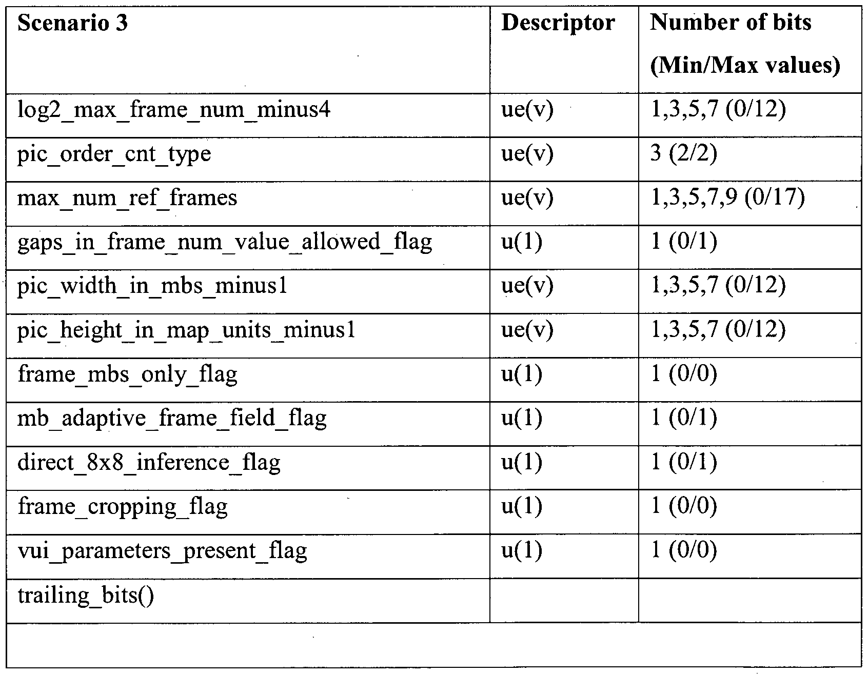
[00162] Table 13
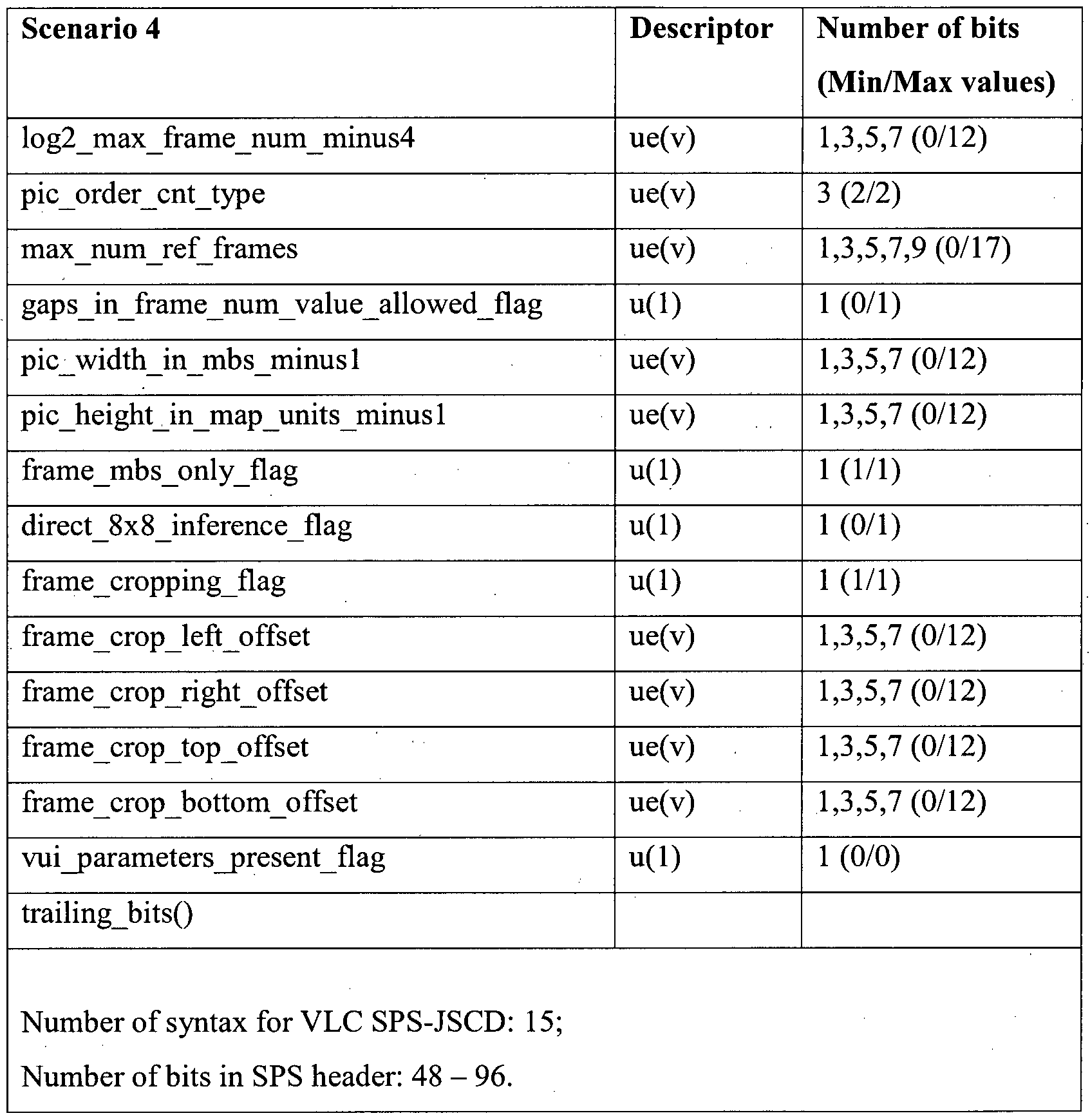

Number of syntax for VLC SPS-JSCD: 16;
Number of bits in SPS header: 48 - 104.
[00165] Table 16
Scenario 7 Descriptor Number of bits
(Min/Max values) log2_max_frame_num_minus4 ue(v) 1,3,5,7 (0/12) pic order cnt type ue(v) 3 (2/2)
max_num_ref_frames ue(v) 1,3,5,7,9 (0/17) gaps_in_frame_num_value_allowed_flag u(l) 1 (0/1)
pic_width_in_mbs_minus 1 ue(v) 1 ,3,5,7 (0/12) pic height in map units minus 1 ue(v) 1,3,5,7 (0/12) frame_mbs_only_flag u(l) 1 (0/0)
mb_adaptive_frame_field_flag u(l) 1 (0/1)
direct_8x8_inference_flag u(l) 1 (0/1)
frame_cropping_flag u(l) 1 (1/1)
frame crop_left_offset ue(v) 1,3,5,7 (0/12) frame crop _right_offset ue(v) 1,3,5,7 (0/12) frame_crop_top_offset ue(v) 1,3,5,7 (0/12) frame_crop_bottom_offset ue(v) 1,3,5,7 (0/12) vui_parameters_present_flag u(l) 1 (0/0) trailing_bits()
Number of syntax for VLC SPS-JSCD: 16;
Number of bits in SPS header: 48 - 96.
[00166] Table 17
Scenario 8 Descriptor Number of bits
(Min/Max values) log2_max_frame_num_minus4 ue(v) 1,3,5,7 (0/12) pic order_cnt_typ e ue(v) 1 (0/0) log2 max_pic order cnt lsb minus4 ue(v) 1,3,5,7 (0/12) max_num_ref_frames ue(v) 1,3,5,7,9 (0/17) gaps in frame num value allowed flag u(l) 1 (0/1) pic_width_in_mbs_minus 1 ue(v) 1,3,5,7 (0/12) pic_height_in_map_units_minus 1 ue(v) 1,3,5,7 (0/12) frame mbs only flag u(l) 1 (0/0) mb_adaptive_frame_field_flag u(l) 1 (0/1) direct_8x8_inference_flag u(l) 1 (0/1) frame cropping fiag u(l) 1 (1/1) frame_crop_left_offset ue(v) 1,3,5,7 (0/12) frame_crop_right_offset ue(v) 1,3,5,7 (0/12) frame_crop_top_offset ue(v) 1,3,5,7 (0/12) frame_crop_bottom_offset ue(v) 1,3,5,7 (0/12)
vui_parametersjpresent_flag u(l) 1 (0/0)
trailing_bits()
Number of syntax for VLC SPS-JSCD: 17;
Number of bits in SPS header: 48 - 104.
[00167] This total number of bits includes the first 25 bits that are assigned to the FLC SPS-JSCD 406. Note again that the total number of bits in the SPS header is a multiple of 8. In Tables 10 to 17, under the (Min/Max values) column, (x/x) denotes that x is the one and only possible value for the associated syntax.
[00168] Each scenario has a fixed number of syntax and the description of these syntax is fixed as well. Hence each scenario has its own specific trellis, and may be decoded using the BCJR MAP or LogMAP algorithm, which is understood and appreciated to be, for example, the typical BCJR MAP or LogMAP algorithm.
[00169] As an example, the LogMAP algorithm is used in the simulation. More explicitly, the VLC SPS-JSCD (e.g., the VLC SPS-JSCD 408 of FIG. 4) has 8 parallel LogMAP decoders performing the decoding on each of these 8 scenario-specific trellis as shown in FIG. 7. In FIG. 7, an input 700 is fed into 8 parallel LogMAP decoders 702, the outputs of which enters an unit 704 for selecting the decoder with the metric from the 8 parallel LogMAP decoders 702 to provide an output 706.
[00170] The trellis having the highest metric after the decoding is deemed as the desired trellis and the output 706 from this trellis decoding is used. The output 706 may comprise or consist of the decoded SPS header pertaining to the winning scenario as well as the extrinsic information.
[00171] It may be useful to modify the trellis so that the decoding can be performed more efficiently. In conventional trellis terminalogy, the y-axis of the trellis usually symbolizes the state. The total number of states ultimately determines the complexity of the decoder. Hence it is often desirable to keep the number of states as small as possible. Upon examining the trellis of FIG. 5 and FIG. 6 closely, it is observed that the y-axis
represents the bit index, which is equivalent to the state. Thus, the complexity of the SPS- JSCD trellis is directly proportional to the total number of bits. Furthermore, many 'empty' nodes in the trellis (i.e., nodes without any branches) may be observed. This is an inefficient way of representing a trellis. It is possible to reduce the complexity and improve the efficiency by following a transformation rule. Based on this transformation rule, the bit index n in the y-axis is transformed to a state v according to
(6) where x denotes the current syntax index of the x-axis and lmin is the minimum length of the VLC, which is 1 in this case. Using this transformation rule, the transformed trellis of FIG. 6 is shown in FIG. 8, where the y-axis is changed from the bit index to the state.
[00172] The transformed trellis (in FIG. 8) is now more compact, which makes the decoding more efficient. More importantly, all branches end at an even-number state, unlike the original trellis whereby the branches may either end at an odd or an even number bit index. This is due to the fact that all the syntax, except for the trailing bits, have an odd number of bits and by applying the transformation rule of Equation (6), the resulting state is always an even number. This is advantageous because now the decoding needs only to keep track of the even-number states, which in turn reduces the complexity of the decoder. On the other hand, the number of trailing bits can be even or odd. But because it is the last syntax, all branches terminate at the same state, which the decoder needs to track in any case.
[00173] Based on this transformed trellis, the LogMAP algorithm is performed as follows. In the LogMAP algorithm for the SPS-JSCD, the forward and backward recursive calculation may be employed. The forward recursive calculation of the ak (s) LLR values is given by
 where k is the current syntax index, as denoted by the x-axis, and s' and s denote the previous state and current state, respectively. The index m is required here because for a given syntax index k, the state transition from s' to s may contain several branches and m refers to the m-th branch.
[00174] Similarly, the backward recursive calculation of the fik_x (s) LLR values is given by

[00175] The initialization is such that ct0 (0) = 0 and βΝ ) = 0 , where N is the total number of syntax and s is the termination state, while all other values are set to a value close to negative infinity.
[00176] For both Equation (7) and Equation (8), the summation may be simplified by using the following Jacobian algorithm log[exp(x, ) + ex (A:2 )] = max( , ,x2 ) + log[l + expl \x,—x .I)] 00
[00177] Finally, the transition probability LLR values yk m (s',s) in Equation (7) and
Equation (8) may be calculated from the received LLR values obtained from the channel as well as the a priori information, if any.
[00178] Let the total number of branches linking the previous state s' to the current state s be M. In this case, yk (s s) for the m-th branch having a length nm (i.e., the number of bits) is calculated as
 where L{yn
 y„ given the considered bit x„ of that branch, La (un ) is the a priori LLR information of the considered bit, and Rm is the so-called bias.
[00179] The bias is essential when calculating the transition probabilities involving VLC and is derived as

[00180] From Equation (1 1), it is observed that the bias is different for different length codes. However, if all the codes are of a fixed length, then the bias is the same for all codes and it may be ignored.
[00181] The final LLR value of the n-\W bit, given the received SPS header y is given by

[00182] The extrinsic information is then obtained by subtracting the inputs from

Le (un ) = L(u„\y) - L(yn ) - La (un ) (13)
[00183] It is noted that the LogMAP decoder is only able to decode and possibly correct any bit errors occurring in the VLC-based syntax because these codes possess a certain amount of redundancies. It is unable to detect bit errors for the FLC boolean- based syntax such as direct_8x8_inference_flag.
[00184] When it comes to selecting the best scenario out of the 8, one way of doing it is to compare the sum of
 for each scenario and then select the one having the highest value. While this method does work, it is noticed that sometimes the wrong scenario may be chosen. This is because the SPS header is essentially not an error correction code. Hence even with the different scenarios, the decoded outputs from these scenarios are quite similar.
[00185] For example, if scenario 2 (see Table 11) and scenario 5 (see Table 14), the first 7 syntax are the same, which constitutes more than half of the total syntax. Hence output LLR values of these first 7 syntax from the two scenarios are almost similar. The same phenomenon may be observed between scenario 2 and scenario 6 (see Table 15) as well as between other scenarios. Thus, when comparing the accumulated sum of the LLR outputs, the margin of error is considerably (very) small.
[00186] Most of the scenarios have a different number of syntax. But the total number of bits considered is always fixed. Hence according to the transformation rule of Equation (6), the trellis of these scenarios have a different termination state. A better distinction may be achieved if the LLR value of the different scenarios at the termination state are compared. This selection criteria is used in the simulations.
[00187] The block diagram of the receiver configuration with an SPS-JSCD 900 is shown in FIG. 9, where perfect synchronization is assumed, i.e., no synchronization is required. The SPS-JSCD 900 has prior knowledge of the exact location of the SPS header in the packet. The SPS-JSCD 900 is invoked after the turbo decoder 902 has completed its decoding procedure, as demonstrated by the SPS-JSCD activation switch 904 shown in FIG. 9.
[00188] The number of iterations the turbo decoder took to complete its decoding is denoted by Ninner. Each turbo decoder iteration is defined as an inner iteration. The input to the SPS-JSCD may comprise or consist of the LLR sum of the received systematic soft bits from the channel as well as the extrinsic information 906, 908 from both the 1st and 2nd constituent RSC decoders 910, 912 of the turbo decoder 902.
[00189] After the SPS-JSCD 900 has finished its decoding, the extrinsic information from its output 914, as given in Equation (13), is added to the extrinsic information 908 obtained from the 2nd constituent RSC decoder 912 by an adder 916 and the resultant output from the summation 918 is passed to the 1st constituent RSC decoder 910. The rationale behind this is to improve the a priori information going into the 1st constituent RSC decoder 910 during the next set of inner iterations. Each time the SPS-JSCD 900 is activated and new extrinsic information from the SPS-JSCD 914 is fedback to the turbo decoder 902, this is counted as one outer iteration. The number of outer iterations is denoted by Nouter. Note that the same SPS-JSCD extrinsic information 914 may be used for each and every inner iteration of the turbo decoding. This extrinsic information 914 is initialized to zero at the 0th outer iteration. The performance and complexity of the receiver 920 is highly dependent on the two parameters Ninner and Nouter. As such, a receiver configuration with the designation RCSPS-JSCD (Ninner, Nouter) is denoted, where the subscript SPS-JSCD specifies that the receiver configuration (RC) only has a SPS-JSCD 900 with perfect synchronization.
PPS-JSCD
[00190] PPS-JSCD decodes the PPS header based on its syntax structure. The PPS- JSCD uses a trellis-based decoding, similar to VLC SPS-JSCD.
[00191] Similar assumptions may be made for the PPS header syntax to simplify the PPS-JSCD in accordance to various embodiments.
1. The syntax indicated by Table Row Nos. 3.6 to 3.24 in Table 3 corresponds to the case when a picture frame is represented by more than one slice. It is assumed that there is only one slice per frame. Hence, those syntax in Table Row Nos. 3.6 to 3.24 is not used and they are considered in the PPS-JSCD.
2. The syntax indicated by Table Row Nos. 3.35 to 3.48 in Table 3 are applicable to a more advanced video encoding process. Since basic video encoding is used,
these syntax are not included in the PPS-JSCD in accordance to various embodiments.
[00192] Hence, after taking these two assumptions into account, the simplified H.264 PPS header data syntax is shown in Table 18.
[00193] Table 18

redundant_pic_cnt_present_flag u(l)
rbsp_trailing_bits() (1-8 bits)
}
[00194] The PPS-JSCD in accordance to various embodiments is designed based on this simplified PPS header data syntax. In a way, these assumptions may be considered as a priori information, where the JSCD has an idea beforehand of what type of video it is processing and so adapting its decoding approach accordingly.
[00195] Looking at the PPS header syntax of Table 18, it comprises a combination of FLC, as denoted by u(n), and VLC, as denoted by ue(v) or se(v). This arrangement is similar, but not identical, to any one of the SPS header scenarios syntax given in Tables 10 to 17. Hence the same trellis-based decoding algorithm employed for the VLC SPS- JSCD 408 of FIG. 4, as discussed previously, may also be used to decode the PPS header.
[00196] The trellis for the PPS-JSCD may be very different from the VLC SPS-JSCD 408 due to the different FLC/VLC arrangement. But computation wise, it is exactly the same as that of the VLC SPS-JSCD 408. Hence, all the equations for calculating the branch metrics and the extrinsic information given previously under the VLC SPS-JSCD 408 framework are applicable to the PPS-JSCD.
[00197] Lastly, from Table 18 it is noted that there are no //" statements in the PPS header, unlike that of the SPS header. So basically there is only one scenario for the PPS header, which makes the PPS-JSCD less complex.
[00198] If the receiver, for example, the receiver 118 of FIG. 1, has prior knowledge about the exact location of the PPS header, then the PPS-JSCD is suffice to decode the header. In this case, the receiver configuration is no different from that of the receiver configuration with only the SPS-JSCD and perfect synchronization, as shown in FIG. 9.
[00199] The receiver configuration 1000 with only the PPS-JSCD 1002 with perfect synchronization is shown in FIG. 10. Following the previous notation, this configuration is referred to as RCPPS-JSCD (Ninner, Nouter).
[00200] It is possible to have both SPS and PPS headers residing within a packet. In such situations, both the SPS-JSCD and PPS-JSCD, for example, the SPS-JSCD 900 of FIG. 9 and the PPS-JSCD 1002 of FIG. 10, may be activated. Again, it is assumed that the receiver has prior knowledge about the exact locations of the SPS and PPS headers. Hence, both JSCDs 1 100 may be activated without any synchronization. The receiver configuration 1 102 is shown in FIG. 1 1 with the notation RCJSCDS (Ni er, Nouter).
[00201] In various embodiments, the decoder 200 of FIG. 2 may further include a synchronizer configured to determine a presence of a complete network abstract layer (NAL) unit in the video data packet, wherein the complete NAL unit comprises a NAL unit sandwiched between two prefixes, and to determine the location of the encoded header in the video data packet and/or the length of the encoded header from the video data packet.
[00202] FIG. 12 shows a complete NAL unit 1200 which includes two prefixes 1202, 1204 sandwiching a NAL unit identifier 1206 followed by a raw byte sequence payload (PvBSP) 1208. The prefix 1202 and part of the NAL unit identifier 1206 make a front sychronization word (FSW) 1210. A remainder part of the NAL unit identifier 1206 is referred to as header type (HT) 1212. The prefix 1204 makes a rear sychronization word (RSW) 1214.
[00203] For example, the prefix 1202, the NAL unit identifier 1206 and the RBSP 1208 may be the prefix 304, the NAL unit identifier 306 and the RBSP 308 of FIG. 3, respectively.
[00204] In various embodiments, the synchronizer may include a correlation unit configured to generate a plurality of synchronization patterns, to correlate each of the synchronization patterns with soft information of the video data packet to obtain respective correlation metrics and to compare each of the respective correlation metrics against a predefined threshold.
[00205] In various embodiments, the correlation unit may be configured to correlate the each of the synchronization patterns with the soft information of the video data packet by sliding the each of the synchronization patterns across the video data packet to search
for a similar pattern in the packet. The correlation unit may be configured to perform sliding in a byte-by-byte format.
[00206] In various embodiments, the synchronizer may further include a sorting unit configured to sort the each of the plurality of synchronization patterns into different groups based on header types; and a selection unit configured to determine for each group, a synchronization pattern that most likely comprises a header corresponding to the header type of that group.
[00207] In various embodiments, the selection unit may further be configured to utilize the circuit 204 (FIG. 2) to decode the respective encoded headers of the sorted synchronization patterns for each group.
[00208] Synchronization is achieved with the aid of predefined synchronization words, which are normally inserted periodically into the transmitted bitstream. At a receiver, for example, the receiver 118 of FIG. 1, a synchronizer searches for these synchronization words in each period in order to establish synchronization. The prefixes, for example, the prefix 304 of FIG. 3, found in a H.264 encoded video sequence, for example, the H.264 encoded video sequence 300 of FIG. 3, may be considered as synchronization words, even though they are not meant for synchronization at the physical layer.
[00209] Various embodiments address the possibility of exploiting these synchronization words or prefixes so that synchronization may be performed at the physical layer.
[00210] Most received packets do not contain the SPS and PPS headers. The SPS- JSCD and PPS-JSCD must be conscious of the presence or absence of headers in the received packet. The headers, if present, usually constitutes only a small portion in the received packet. The location of these headers is usually not fixed, due to the varying length of the encoded source. The SPS-JSCD and PPS-JSCD must have knowledge of the header location in order to commence decoding. The trellis-based decoding of the VLC SPS-JSCD and PPS-JSCD must have knowledge of the length of the header in order to decode properly. The header length is usually not fixed, again due to the varying length of the encoded source.
[00211] There are two objectives that the synchronization algorithm needs to achieve. Firstly the synchronizer needs to detect the presence or absence of a complete NAL unit 1200 (FIG. 12) within a received packet. The complete NAL unit 1200 as one having the prefixes 1202, 1204 on both ends. The prefix 1202 at the front end belongs to the considered NAL unit while the prefix 1204 at the rear end belongs to the next NAL unit. Detecting the presence of a complete NAL unit 1200 reveals the location of the NAL unit within the received packet as well as the number of bits it carries, which are the two most critical parameters for the JSCD. In this case, the JSCD is invoked. If no complete NAL unit is found, the synchronization is deemed unsuccessful and the JSCD is not activated.
[00212] The second objective for the synchronizer is to determine if the complete NAL unit contains the SPS header or the PPS header. If it does, then its RBSP is pushed to the SPS-JSCD or the PPS-JSCD, respectively.
[00213] Key assumptions are made for the synchronizer: -
1. It is assumed that no VCL NAL unit may be complete. This is a valid assumption because a VCL NAL unit typically spans over many bits such that it is not likely to find a complete VCL NAL unit within a received packet.
2. If by any chance the packet size is large enough to accommodate a complete VCL NAL unit, the maximum allowable length for a complete NAL unit (e.g., the complete NAL unit 1200 of FIG. 12) have to be limited. This is borne from the fact that the length of the SPS or PPS header is usually much shorter than that of the VCL RBSP. Based on the simplified SPS header model as given in Table 5, the maximum length of the SPS header is only 104 bits and the RBSP of the VCL NAL unit is much longer than that. The maximum length of the PPS header is even shorter, spanning at most 48 bits, as given in Table 18. Thus, given this assumption, the synchronizer ignores any NAL unit whose RBSP length exceeds beyond the limit (which is 104 bits) and only non-VCL NAL units are detected, which contain either the SPS or PPS header.
[00214] The synchronization algorithm may be sub-divided into 3 phases; mainly correlation, sorting, and selection.
[00215] Correlation Phase:-
[00216] As mentioned previously, the synchronizer first needs to determine the presence of a complete NAL unit (e.g., the complete NAL unit 1200 of FIG. 12). This is achieved by identifying the two prefixes 1202, 1204 at the front and rear end of the NAL unit. The NAL unit syntax for the SPS header and the PPS header have the following bit sequence : 0 1 1 0 0 1 1 1 = 0x67 and 0 1 1 0 1 0 0 0 = 0x68, respectively. It is noted that the first 4 MSB of both headers are identical. So it may be considered that the first 4 bits of the NAL unit syntax is part of the front end synchronization word. As such, the front end synchronization word consists of the 32-bit prefix plus the 4-bit NAL unit syntax. This is referred to as the Front Synchronization Word (FSW) 1210 (FIG. 12) having a hexadecimal format 0x000000016. The rear end synchronization word still retains the 32- bit prefix structure and it is referred to as the Rear Synchronization Word (RSW) 1214 (FIG. 12).
[00217] The number of bits between the start of the FSW and the start of the RSW constitute the total number of bits in the NAL unit. Subtracting the length of the FSW
1210, i.e., 36 bits, from this number gives the length of the RBSP 1208 plus the 4 bits of the nal_unit_type, which identifies the type of header. This 4-bit sequence is referred to as the header type (HT) 1212 (FIG. 12). Unfortunately, the number of bits in the RBSP
1208 is an unknown variable. However, based on the simplified SPS header model as given in Table 5, the RBSP length of the SPS header is ranged from a minimum of 40 bits to a maximum of 104 bits, in multiples of 8. In addition, the simplified PPS header model given in Table 18 shows that the RBSP length of the PPS header ranges from 24 bits to
48 bits, again in multiples of 8. Thus a total of 1 1 unique synchronization patterns, where each pattern takes on a particular header length, are created as shown in FIG. 13.
[00218] The nomenclatures of FIG. 13 with respect to the FSW 1210, the HT 1212 and the RSW 1214 of FIG. 12 are as follows:
NRBSP 1300 - Length of the RBSP
NNAL 1302 - Length of the NAL unit
Npattern 1304 - Length of the synchronization pattern.
[00219] The different synchronization patterns are distinguised with a supercript k, i.e.
H A oern k = l,..., U.
[00220] Each of these 1 1 synchronization patterns slides across the received packet in order to search for a similar pattern in the packet. Sliding is performed in a byte-by-byte format. Similar to the conventional synchronization methods, the search is based on correlating the pattern with the soft information of the received sequence and then comparing the obtained correlation metric against a predefined threshold. The correlation is only done on the FSW 1210 and RSW 1214, but not the HT 1212. The main purpose of the predefined threshold is to ensure that when the received packet does not contain any header NAL unit, the correlation metrics of all synchronization patterns fall below the threshold and the synchronization becomes unsuccessful. Invoking the JSCDs when no SPS or PPS header is present have a undesirable effect on the packet performance, a phenomenon that should be avoided.
[00221] The input to the synchronizer corresponds to the Log-Likelihood Ratio (LLR) output of the turbo decoder, for example, similar to the turbo decoder 902 of FIG. 9. For a more efficient comparison, the LLR output is converted to its equivalent soft information using the following probability equations.


[00222] The correlation metric Cn k is obtained using the following equation.
Cn,k =∑P(un+x =■ FSW(b, )) +∑P(un+N> +< = RSW(bj )) (16) =0 =0 where FSW(¾) and RSW(¾) represent the ith bit in the FSW 1210 and RSW 1214, respectively, and n denotes the bit position in the packet. Since the pattern slides across the packet in a byte-by-byte format, n only takes on the values 0, 8, 16, is the received packet size. For each slide across the packet, the correlation metric for the FSW 1210 is fixed for all synchronization patterns. Only the correlation metric of the RSW 1214 is different for different patterns, depending on the length of the pattern. This property is exploited in order to reduce the complexity in terms of the number of addition operations. Complexity may be reduced further by first calculating all the possible correlation metrics for the FSW 1210 and the RSW 1214 across the packet. After that, it is just a matter of adding the appropriate FSW and RSW correlation metrics to obtain the correlation metric for the pattern.
[00223] The total number of correlation metrics obtained for the all the synchronization patterns is given by
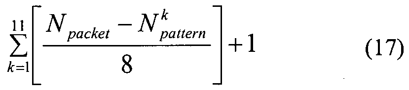
[00225] Sorting Phase:-
[00226] The next step is to sort these patterns by the type of headers, i.e. SPS or PPS header. To do this, the a priori information regarding the headers is used. Recall that the length of the SPS header ranges from 40 bits to 104 bits, while the length of the PPS header ranges from 24 bits to 48 bits. This means that all patterns with RBSP length greater than 48 bits belong to the SPS header. Likewise all patterns with RBSP length less than 40 bits belong to the PPS header. The only ambiguity here is for patterns having RBSP length of 40 and 48, since these patterns may belong to either the SPS header or the PPS header. In order to solve this ambiguity problem, the 4-bit HT portion of these ambiguous patterns is correlated against "0 1 1 1" of the SPS header type and "1 0 0 0" of the PPS header type. The higher correlation value is the decided type. At the end of the sorting phase, there are two shortlists of patterns, one for the SPS header and one for the PPS header. The selection phase next determines which pattern in each shortlist is most likely to contain the respective headers.
[002271 JSCD-assisted Selection Phase:-
[00228] Now with the patterns sorted into the SPS header type and the PPS header type, the winning pattern of each type, i.e., the pattern that most likely contains the respective headers is to be determined. Normally, the synchronization pattern that corresponds to the highest correlation metric that exceeds the threshold is deemed to be the winner. However, in some simulation examples (to be discussed later), selecting this synchronization pattern does not give the best performance. This is because the correct
synchronization pattern may not have the highest correlation metric. The performance by selecting the best M synchronization patterns having the highest correlation metric for each header type may be improved. If there are fewer than M synchronization patterns of the header type, then only these few synchronization patterns are considered. In order to select the best synchronization pattern of each header type, but not necessarily having the highest correlation metric, the corresponding SPS-JSCD and the PPS-JSCD are made use of to aid the decision.
[00229] Recall that in the SPS-JSCD in accordance to various embodiments, a scenario-based trellis is used to select the best SPS header scenario based on the highest trellis branch metric. Typically, the scenario that corresponds to the actual SPS header gives the highest branch metric. Similarly, since these M synchronization patterns may correspond to a different length of the NResp, their corresponding RBSP may also be considered as different scenarios. Hence by applying the same principle, the RBSP that corresponds to the highest trellis branch metric amongst the M SPS-JSCD outputs may be the decoded SPS header. The associated extrinsic output from this best RBSP sequence may be fedback to the turbo decoder, for example, similar to the turbo decoder 902 of FIG. 9 for further iterative processing. The same PPS-JSCD assisted selection procedure is also used for the patterns corresponding to the PPS header.
[00230] The value of M is to be chosen wisely. If M is too low, then the possibility of detecting the correct synchronization pattern is reduced. Hence, intuitively, a higher M value is desirable. However, the SPS header and PPS header are not error correcting codes, so given a multitude of synchronization patterns possibilities, it is also not easy for the SPS-JSCD and PPS-JSCD to efficiently distinguish the best synchronization pattern.
[00231] A flow diagram depicting the synchronization algorithm is shown in FIG. 14.
This synchronization algorithm also works for cases when only one type of header is in the packet or no headers are in the packet. When only one type of header is present, then ideally the sorting phase sorts all the patterns into the shortlist corresponding to that header type. If no headers are present, then ideally the correlation metric of all patterns falls below the threshold and the JSCDs is not activated. Of course, in practice, some irregularities from the ideal case may be expected.
[00232] In FIG. 14, the correlation algorithm 1400 starts with converting LLR to soft information 1402, followed by obtaining correlation metric for all synchronization patterns 1404 and removing all patterns with correlation metric below or less than the threshold 1406. The correlation algorithm 1400 then checks if any pattern is left at 1408. If yes, the sorting algorithm 1410 starts. If no, the correlation algorithm 1400 ends.
[00233] The sorting algortihm 1410 starts with checking whether all patterns have been sorted at 1412. If yes, the JSCD-assisted selection algorithm 1414 starts. If no, the sorting algorithm 1410 checks if NRBSP of the pattern is more than 48 bits at 1416. If yes, the sorting algorithm 1410 places the pattern in the SPS header shortlist at 1418 and proceeds back to 1412. If no, the sorting algorithm 1410 checks if JVRBSP of the pattern is less than 40 bits at 1420. If yes, the sorting algorithm 1410 places the pattern in the PPS header shortlist at 1422 and proceeds back to 1412. If no, the sorting algorithm 1410 correlates HT at 1424 and then check if SPS HT is more than PPS HT at 1426. If yes, the sorting algorithm 1410 places the pattern in the SPS header shortlist at 1428 and proceeds back to 1412. If no, the sorting algorithm 1410 places the pattern in the PPS header shortlist at 1430 and proceeds back to 1412.
[00234] The JSCD-assisted selection algorithm 1414 starts with selecting the top M patterns having the highest correlation metric at 1432, followed by decoding the RBSP of the patterns using JSCD and noting the branch metric at 1434, and subsequently providing feedback on the extrinsic information having the highest branch metric at 1436. The JSCD-assisted selection algorithm 1414 is for both SPS-JSCD and PPS-JSCD.
[00235] The receiver configuration with synchronization 1500 is shown in FIG. 15 and follows the notation RCSYNC (Ni„ner, Nouter). The JSCD 1502 is specified as a general term in FilG. 15 in this case because it is not known which JSCD is activated. For example, both the SPS and PPS headers may be present in the packet but if the synchronization is only able to detect an SPS header after the sorting phase, only the SPS-JSCD is activated. Likewise, if only the SPS header is present in the packet but the synchronization somehow detected the presence of a PPS header after the sorting phase, the PPS-JSCD is activated.
[00236] In a second aspect, a receiver including a decoder in accordance to various embodiments is provided. For example, the receiver may be the receiver 1 18 of FIG. 1, the receiver 920 of FIG. 9, the receiver 1000 of FIG. 10, the receiver 1102 of FIG. 1 1, or the receiver 1500 of FIG. 15.
[00237] In a third aspect, a method of decoding an encoded header of a video data packet is provided as shown in FIG. 16. In FIG. 16, the method 1600 includes receiving an encoded header of a video data packet 1602; and decoding the encoded header using joint source-channel decoding (JSCD) 1604.
[00238] The terms "decoding", "encoded header", "using", and "JSCD" may be as defined above.
[00239] In various embodiments, the video sequence may be a H.264 video sequence.
[00240] In various embodiments, the step of decoding the encoded header using joint source-channel decoding (JSCD) 1604 may include constructing a plurality of trellis.
[00241] As used herein, the term "constructing" may refer to "building", "forming", "evaluating", or "computing".
[00242] In one embodiment, the step of decoding the encoded header using joint source-channel decoding (JSCD) 1604 may include determining a code from the received encoded header or a part thereof, and generating a bit sequence and a probability value by using the code, the probability value indicating the likelihood that the generated bit sequence is a correctly decoded header or a part thereof of the video data packet.
[00243] The terms "determining", "code", "generating", "correctly decoded header" may be as defined above.
[00244] In this embodiment, the step of determining the code may include generating a plurality of codes and respective probability values from the received encoded header or the part thereof and selecting from the plurality of codes the code based on the respective probability values. The step of selecting the code may include selecting from the plurality of codes the code having the largest probability value.
[00245] The step of generating the bit sequence and the probability value may include performing a process operating on a mode of posterior distribution, or on maximum a posteriori probability (MAP), or on BCJR MAP or logMAP.
[00246] In various embodiments, the method 1600 may further include converting the bit indexes of the encoded header into respective syntax indexes for determining the code. The method 1600 may further include transforming the bit indexes into states such that each state has an even number of bits.
[00247] The step of generating the probability value may include determining the likelihood that each bit of the bit sequence corresponds to a respective bit of the correctly decoded header or the part thereof.
[00248] In various embodiments, when the encoded header is an encoded SPS header, the method 1600 may further include decoding another part of the encoded SPS header comprising a fixed length code of more than 1 bit.
[00249] For example, the fixed length code may be 25 bits.
[00250] In various embodiments, the method 1600 may further include dividing the encoded header received by the input unit into the part comprising the variable length code and the other part comprising the fixed length code.
[00251] The method 1600 may further include multiplexing the generated bit sequence and an output obtained from decoding the other part of the encoded SPS header comprising the fixed length code of more than 1 bit.
[00252] The terms "dividing" and "multiplexing" may be as defined above.
[00253] In various embodiments, the method 1600 may further include generating extrinsic information for decoding the encoded header.
[00254] The method 1600 may further include receiving side information from a transmitter sending the video data packet, the side information indicating the location of the encoded header in the video data packet, the length of the encoded header, or both.
[00255] The phrases "extrinsic information" and "side information" are as defined above.
[00256] In various embodiments, the method 1600 may further include determining a presence of a complete network abstract layer (NAL) unit in the video data packet, wherein the complete NAL unit comprises the NAL unit sandwiched between two prefixes; and determining the location of the encoded header in the video data packet and/or the length of the encoded header from the video data packet.
[00257] The step of determining the location of the encoded header in the video data packet and/or the length of the encoded header from the video data packet may include generating a plurality of synchronization patterns; correlating each of the synchronization patterns with soft information of the video data packet to obtain respective correlation metrics; and comparing each of the respective correlation metrics against a predefined threshold.
[00258] The phrases "complete NAL unit", "correlating", "soft information" may be defined as above.
[00259] The step of correlating the each of the synchronization patterns with the soft information of the video data packet may including sliding the each of the synchronization patterns across the video data packet to search for a similar pattern in the packet. Sliding may be in a byte-by-byte format.
[00260] In various embodiments, the method 1600 may further include sorting the each of the plurality of synchronization patterns into different groups based on header types; and determining for each group, a synchronization pattern that most likely comprises a header corresponding to the header type of that group.
[00261] The step of determining the synchronization pattern that most likely comprises the header corresponding to the header type may include decoding the respective encoded headers of the sorted synchronization patterns for each group.
[00262] In various embodiments, the method 1600 may include providing a priori information for a subsequent iteration of decoding by utilizing a feedback of a combination of extrinsic information obtained from decoding the encoded header and the generated extrinsic information for decoding the encoded header.
[00263] The following non-limiting examples are described with respect to various embodiments of the invention, as follows.
Simulation Setup
[00264] The transmitter model employed in the simulation is shown in FIG. 17. In
FIG. 17, a JM H.264 encoder 1700 is coupled to a SPS+PPS header complete NAL unit extraction 1702 which is in turn coupled to a SPS+PPS header complete NAL unit
insertion 1704. The SPS+PPS header complete NAL unit insertion 1704 also receives from a random data generator 1706. The output of the SPS+PPS header complete NAL unit insertion 1704 is fed into a turbo encoder 1708. BPSK modulation 1710 is used such that the encoded signal (i.e., received signal 1712) is transmitted through an additive white Gaussian noise (AWGN) channel 1714.
[00265] The test video sequence used is the foreman_qcif.yuv, which is encoded by the JM encoder to generate the corresponding H.264 video sequence. Specifically, the generated H.264 video sequence has a Baseline profile with a frame pattern
IPPPPIPPPPIP There are a total of 300 frames. The complete SPS and PPS header
NAL unit are extracted from the encoded H.264 video sequence. These two NAL units are contiguous in the foreman test video sequence and so their complete NAL unit overlaps, as shown in FIG. 18. In FIG. 18, two prefixes 1800, 1802 sandwiches a SPS NAL identifier 1804, and a SPS header 1806, denoted as the complete SPS NAL unit 1808. The prefix 1802 further sandwiches a PPS NAL identifier 1810 and a PPS header 1812 with another prefix 1814, denoted as the complete PPS NAL unit 1816.
[00266] FIG. 19 shows a SPS header NAL unit 1900. Based on the test video sequence, the total number of bits in the SPS header, including the 8 trailing bits required to round the total number of bits in the header to a multiple of 8 (byte) is 64. This excludes the 32-bit sync word 1902, 1904 and the 8 bits needed to represent the NAL unit syntax 1906. The N-bit SPS header 1908 is a 64-bit SPS header being referred to as the basis SPS header from hereafter. Table 19 shows the bit pattern of the basis SPS header.
[00267] Table 19

level idc 00101000 40
seq parameter set id 1 0 (Fixed in JM encoder) log2_max_frame_num_minus~4 1 0
pic order cnt type 1 0
log2_max_pic_order_cnt_lsb_minus4 001 11 6
max num ref frames 001 10 5
gaps in frame num value allowed flag 0 0
pic width in mbs minus 1 0001011 10
pic_height_in_map_units_minus 1 0001001 8
frame_mbs_only_flag 1 1
direct_8x8_inference_flag 1 1
frame_cropping_flag 0 0
vui_parameters_present_flag 0 0
trailing bits 10000000
[00268] Likewise, the total number of bits in the PPS header, including the trailing bits is 32. This excludes the 32-bit sync word and the 8-bit NAL unit syntax. This 32-bit PPS header is referred to as the basis PPS header from hereafter. Table 20 shows the bit pattern of the basis PPS header used in the simulations.
[00269] Table 20

num ref idx l l default active minus 1 00101 4
weighted_red_flag 0 0
weighted_bired_idc 00 0
pic_init_qp_minus26 1 0 (Fixed in JM encoder) pic init qs minus26 1 0 (Fixed in JM encoder) chroma qp index offset 1 0
deblocking_filter_control_present_flag 0 0
constrained intra_pred_flag 0 0
redundant_pic_cnt_present_flag 0 0
trailing bits 10000000
[00270] At the start of every simulation run, a sequence of random bits is generated. This sequence of bits is referred to as a packet and the number of bits in this packet is referred to as the packet size. The two contiguous NAL units are inserted in a random position for each run in order to test the efficiency of the synchronization, thus overriding the previously generated random bits. The same NAL units is used for every run during the simulation. If perfect synchronization is assumed, then the SPS-JSCD and/or PPS- JSCD is assumed to have perfect knowledge of the location of their respective headers. This sequence of bits, with the NAL units inserted, is then turbo encoded (i.e., by the turbo encoder 1708 of FIG. 17) according to the 3 GPP TS 25.212 standards. For simplicity sake, it is assumed that the modulation is binary phase shift keying (BPSK), i.e., the BPSK modulation 1710 of FIG. 17. The channel is a purely AWGN channel 1714 (FIG. 17), whereby the noise values is randomly generated for each run of the simulation. For every simulation run, only the packet embedded with the two NAL units is transmitted, since only the performance concerning the SPS header or the PPS header are observed. The remaining video sequence are not transmitted. The received signal 1712 is then passed forward to the receiver for processing.
Performance of SPS-JSCD with perfect synchronization
[00271] The BER and HER of the basis SPS header based on RCSPS-JSCD (Ninner, 1) are shown in FIG. 20 and FIG. 21, respectively, for a rate- 1/3 turbo code having a packet size of 1024. In other words, the SPS-JSCD is only activated once while the number of inner iterations of the turbo decoder is varied. The performance is compared against that without any SPS-JSCD. From FIG. 20, a consistent performance improvement is observed when the SPS-JSCD is employed for any value of Ninner. With Ninner = 8, the inclusion of the SPS-JSCD improved the BER performance by about 0.1 dB as compared to one without any SPS-JSCD at a BER of about 2x1 Oe"4. On the other hand, refering to FIG. 21, the corresponding HER does not improve as much. The reason for this may be because there are still certain bits in the SPS header that the SPS-JSCD cannot correct, as mentioned previously. Any errors in these bits cause a header error, regardless of how many other bits the SPS-JSCD has corrected. Because of this, the corresponding PSNR, as shown in FIG. 22, has only improved slightly when comparing between with and without the SPS-JSCD at Ninner = 8. The achieved PSNR is still about 5-6 dB below the perfect SPS header case.
[00272] For a higher rate turbo code, such as a rate-3/4 code, the performance gain that may be gleaned from RCSPS JSCD (Ninner,l) increases. For example, FIG. 23 shows that
BER of the basis SPS header using RC1 for a rate-3/4 turbo code, in which the performance improvement with SPS-JSCD is about 0.2 dB as compared to one without
SPS-JSCD at a BER of about 10"4. Similarly, it is observed that the corresponding HER, as shown in FIG. 24, do not improve as much. Nevertheless, the improvement is more than that with a rate- 1/3 turbo code. Hence, in terms of the PSNR, a slightly more improvement is observed when the SPS-JSCD is employed, as shown in FIG. 25. The achievable PSNR is now about 2-3 dB off the perfect SPS header case.
[00273] As mentioned previously, the limited performance improvement from the
SPS-JSCD is because there are some bits that the SPS-JSCD cannot correct. These bits can only be corrected by the turbo decoder 1708 (FIG. 17). With Nouter = 1, there is no feedback from the SPS-JSCD. So for Nouter > 1, the turbo decoder 1708 exploits the extrinsic information generated by the SPS-JSCD and then attempt to improve the error
correction capability further. The BER and HER of the basis SPS header based on RCSPS- JSCD (ljNoMte ) are shown in FIG. 26 and FIG. 27, respectively, for a rate-1/3 turbo code having a packet size of 1024, where Nouter = 1,...,8. RCSPS-JSCD (I , Nouter) has improved the performance further. Now, the achievable gain with Nouter = 8 is about 0.2 dB at a BER of 2xl0"4 as compared to only 0.1 dB for Nouter = 1 at the same BER (see FIG. 20). More importantly, the corresponding HER achieves the same amount of gain, as portrayed in FIG. 27, unlike that of Nouter = 1. The reason for this is because with the aid of the feedback from the SPS-JSCD, the bits that cannot be corrected by the SPS-JSCD have the opportunity to be correct by the turbo decoder 1708 in the next set of inner iterations. The probability of being corrected increases with every iteration. This is observed by comparing the HER of FIG. 21 (Nouter = 1) and FIG. 27 N outer = 8). This improvement of the HER has a great impact on the PSNR, as depicted in FIG. 28. It is observed that the achievable PSNR using RCSPS-JSCD ( ,8) is now very close to the error-free SPS header bound, with at most 1 dB loss at the Eb N0 of 0-0.1 dB.
[00274] The previous examples were based on Ninner = 1. The error correction capability may be improved further by increasing the number of inner iterations. The BER simulation results for RCSPS-JSCD (2,Now¾r) is shown in FIG. 29 for a rate- 1/3 turbo code having a packet size of 1024 bits, where Nouier = 1,...,8. The performance without SPS-JSCD with Ninner = 16 is also shown (dashed line) for comparison sake. Comparing this with RCSPS-JSCD (2,8) at a BER of about 2x10~4, it is observed that there is a gain of about 0.25 dB. The corresponding HER for RCSPS-JSCD flouter) is shown in FIG. 30.
[00275] The BER and HER simulation results for RCSPS-JSCD (4,Nouter) and RCSPS-JSCD (6,Nouter) for various values of Nouter are shown in FIG. 31 and FIG. 32, respectively. It is observed that apart from the first iteration and to some extent the second iteration, both RCSPS-JSCD (4,N0Uter) and RCSPS-JSCD (6,N0Uter) have approximately similar performance as the number of outer iterations increases.
[00276] Last but not least, a comparison of the achievable Y PSNR between RCSPS- JSCD (2,8), RCSPS-JSCD (4,6), and RCSPS-JSCD (6,4) is shown in FIG. 33. The Y PSNR obtained from the various combinations of RCSPS-JSCD (NinnerJJouter) are very similar and they are close to the error-free case.
Performance of PPS-JSCD with perfect synchronization
[00277] The BER simulation results of the basis PPS header for RCPPS-JSCD (6,N0Uler) is shown in FIG. 34, based on a rate- 1/3 turbo code having a packet size of 1024 bits, where Nouter = 1,...,4. The corresponding BER without the aid of the PPS-JSCD is also shown for comparison. From FIG. 34, it is observed that with the PPS-JSCD, a gain of about 0.1 dB may be achieved at a BER of lOe"4. For the SPS header case as shown previously, a gain of more than 0.2 dB may be observed with a SPS-JSCD. There are two reasons why the PPS-JSCD achieved a smaller gain as compared to the SPS-JSCD. Firstly, there are greater redundancies found in the SPS header as compared to the PPS header. For instance, the amount of a priori information for the PPS header, in terms of the number of values fixed by the JM encoder, is less than that of the SPS header. Also, redundancies in the SPS header may be derived from at least 4 VLC syntax (depending on the scenario) in addition to the FLC syntax profile idc and level idc. These are the syntax where error corrections may be made by the SPS-JSCD. On the other hand, the PPS header contains at most 4 VLCs. Hence the number of error corrections that may be made by the PPS- JSCD is limited. Secondly, the basis PPS header, which is 32 bits long, is considerably shorter than the basis SPS header, which is 64 bits long. The effect of a shorter header is that the extrinsic information feedback from the JSCD to the turbo decoder is diminished. Hence, the gain that may be obtained from subsequent iterations is not as great as when a longer header is considered.
[00278] Likewise, a similar gain in the basis PPS header HER is observed, as illustrated in FIG. 35, when the PPS-JSCD is invoked. Naturally, due to the poorer performance relative to the SPS-JSCD, the corresponding PSNR, as shown in FIG. 36, do not improve as much as what have been seen for the SPS header previously. In FIG. 36, it is assumed that the SPS header is error-free. So only an error in the basis PPS header gives a total loss of video. Because the basis PPS header has a shorter length, its HER is generally lower. Hence even without the aid of any JSCD, the achievable PSNR with the basis PPS header is higher than that with the basis SPS header. The inclusion of the PPS-
JSCD improves the PSNR by about 2 dB, and this is still about 1.5 dB away from the error-free case.
Performance of SPS-JSCD & PPS-JSCD with perfect synchronization
[00279] Previously, the performance of a standalone SPS-JSCD or PPS-JSCD in accordance to various embodiments is shown. Now the performance when both JSCDs are activated to decode both headers is presented. FIG. 37 shows the BER of the basis SPS header when both SPS-JSCD and PPS-JSCD are activated. As a benchmark, the performance is compared against that when the PPS-JSCD is not used. A very slight improvement in the BER is observed for N outer > 1■ This improvement is wholly due to the extrinsic information feedback from the PPS-JSCD. Obviously when Nouter = 1, there are no feedback from the PPS-JSCD yet and hence no gain is seen, as evident from FIG. 37.
[00280] FIG. 38 shows the BER of the basis PPS header when both SPS-JSCD and PPS-JSCD are activated. This time, the performance is compared against that when the SPS-JSCD is not used. In the case of the basis PPS header, a larger performance improvement of about 0.05 dB is observed. Clearly, the extrinsic information feedback from the SPS-JSCD is more beneficial to the performance of the PPS-JSCD. This is of course due to the fact that the SPS-JSCD itself has a better decoding performance as compared to the PPS-JSCD.
[00281] In the context of the PSNR, a decent improvement of about 3 dB is observed when the SPS-JSCD and PPS-JSCD are invoked, as seen in FIG. 39. This is about 1.5 dB away from the error-free header case.
Performance of SPS-JSCD & PPS-JSCD assisted synchronization
[00282] So far, the examples presented were based on the assumption of perfect synchronization. In other words, the decoding parameters required by the JSCDs were perfectly known. Now the example when the knowledge of these parameters is acquired through the JSCD-assisted synchronization in accordance to various embodiments is presented. The achievable performance if M is set to 1 is investigated. In this case, the
synchronization pattern having the highest correlation metric that exceeds the threshold is the winner. The results for the basis SPS header BER based on RCSYNC (6,N0Uter) is shown in FIG. 40. The threshold is set to 50.0. The outcomes are compared against those with perfect synchronization, i.e. RCJSCDS (6,N0!i¾r). A degradation in performance of about 0.15 dB is observed when compared with the perfect synchronization case. However, this performance is still better than one without any JSCDs. Similar amount of degradation is also observed for the basis PPS header as displayed in FIG. 41.
[00283] Now what happens when M is increased to 4. In this case, the best pattern is selected based on the branch metric of the SPS-JSCD and the PPS-JSCD, instead of the correlation metric. The threshold is again set to 50.0. The results for the basis SPS header BER is shown in FIG. 42. Comparing with = 1, it is observed from the figures that the performance have improved when M is increased to 4. The gap between RCSYNC (6,Nouter) and RCJSCDS (6,Nouter) is now just about 0.05dB. Similar improvement is also observed for the basis PPS header as demonstrated in FIG. 43. This shows that the JSCD based on its branch metric is a good tool to sort out the best synchronization pattern. In terms of the PSNR, there is only a very slight degradation between RCSYNC (6,4) and RCJSCDS (6,4), as shown in FIG. 44.
[00284] However, increasing the value of M does not mean that performance is improved further. A performance comparison between M = 4 and M = 6 is illustrated in FIG. 45 for the basis SPS header and in FIG. 46 for the basis PPS header. It is clearly observed that the performance with M = 4 is always better than that with M = 6. This shows that increasing M does not necessarily lead to an improvement in the performance. Furthermore, increasing M increases the complexity as there are more patterns for the JSCDs to decode.
[00285] If every received packet contains both the SPS and PPS headers, then the threshold is not required because both JSCDs must be activated every time. However, in practical situations, this is not the case. In fact, complete NAL units carrying the SPS header and/or the PPS header occurs infrequently. Hence in most cases, the SPS-JSCD and PPS-JSCD are not be invoked. False activation of the JSCDs naturally lead to a degradation in the performance. The threshold is there to prevent such false activation.
Ideally, the threshold value is set such that when there are no complete NAL units, be it the SPS header or the PPS header, then the correlation metrics corresponding to all synchronization patterns fall below the threshold. So a high threshold is desirable. On the other hand, if the threshold value is set too high, all the correlation metrics may also fall below the threshold if there are really complete NAL units in the packet carrying the headers. The following set of examples investigates the impact of the threshold value when the complete NAL units are present in the packet and when the complete NAL units are not present in the packet.
[00286] First of all, the threshold is increased from 50.0 and 52.0 and compare both performances. The basis SPS header BER and basis PPS header BER are illustrated in FIG. 47 and FIG. 48, respectively. Increasing the threshold to 52.0 does not impact the performance of both headers much. In fact, some minor improvements are observed. So it is concluded that if the headers are present in the packet, similar performance may be gleaned with a threshold of 50.0 or 52.0.
[00287] Now, what happens when no headers are present in the packet. FIG. 49 shows the packet BER performance when no SPS and PPS headers are transmitted. The performance is compared between a threshold of 50.0 and 52.0. When the the threshold is set to a lower value of 50.0, a degradation is seen especially at the lower BER region. This means that sometimes, the correlation metrics of the patterns is above the threshold, even though there are no headers present. The subsequent activation of the JSCDs causes a degradation in the performance. On the other hand, the performance when the threshold is set to 52.0 is the same as a turbo-coded packet. So most, if not all, of the time, the correlation metric of the patterns falls below the threshold and the performance is not affected.
[00288] The examples show that the SPS-JSCD and the PPS-JSCD are able to reduce the error probability of the headers. The margin of improvement may be adjusted by controlling the number of inner and outer iterations. The decoding parameters required by the JSCDs may be acquired by the synchronization algorithm and the resultant performance is not too far away from the perfect synchronization case.
[00289] In the context of various embodiments, the term "about" as applied to a numeric value encompasses the exact value and a variance of +/- 5% of the value.
[00290] While the invention has been particularly shown and described with reference to specific embodiments, it should be understood by those skilled in the art that various changes in form and detail may be made therein without departing from the spirit and scope of the invention as defined by the appended claims. The scope of the invention is thus indicated by the appended claims and all changes which come within the meaning and range of equivalency of the claims are therefore intended to be embraced.
Claims
1. A decoder comprising:
an input unit configured to receive an encoded header of a video data packet; and a circuit configured to decode the encoded header using joint source-channel decoding (JSCD).
2. The decoder of claim 1, wherein the encoded header is an encoded sequence parameter set (SPS) header or an encoded picture parameter set (PPS) header.
3. The decoder of claim 1, wherein the encoded header or a part thereof comprises a variable length code.
4. The decoder of claim 1 , wherein the decoder is a trellis-based decoder.
5. The decoder of claim 1, wherein when decoding the encoded header using joint source-channel decoding (JSCD), the circuit is configured to determine a code from the received encoded header or a part thereof, and using the code to generate a bit sequence and a probability value, the probability value indicating the likelihood that the generated bit sequence is a correctly decoded header or a part thereof of the video data packet.
6. The decoder of claim 5, wherein when determining the code, the circuit is configured to generate a plurality of codes and respective probability values from the received encoded header or the part thereof and to select from the plurality of codes the code based on the respective probability values.
7. The decoder of claim 6, wherein the circuit is configured to select from the plurality of codes the code having the largest probability value.
8. The decoder of claim 5, wherein the circuit operates based on a mode of posterior distribution.
9. The decoder of claim 5, wherein the circuit operates based on maximum a posteriori probability (MAP).
10. The decoder of claim 9, wherein the circuit operates based on BCJR MAP or logMAP.
11. The decoder of claim 10, wherein the encoded header comprises bit indexes; and wherein the decoder further comprises a syntax converter configured to convert the bit indexes into respective syntax indexes which the circuit uses to determine the code.
12. The decoder of claim 3, wherein when the encoded header is an encoded SPS header, the decoder further comprises a sub-decoder configured to decode another part of the encoded SPS header comprising a fixed length code of more than 1 bit.
13. The decoder of claim 12, wherein the fixed length code comprises 25 bits.
14. The decoder of claim 12, further comprising a demultiplexer configured to divide the encoded header received by the input unit into the part comprising the variable length code for the circuit and the other part comprising the fixed length code for the sub- decoder.
15. The decoder of claim 12, further comprising a multiplexer configured to multiplex the bit sequence generated by the circuit and a decoded output from the sub-decoder.
16. The decoder of claim 1, further comprising a convolutional decoding unit configured to generate extrinsic information for the circuit.
17. The decoder of claim 16, wherein the convolutional decoding unit is further configured to receive side information from a transmitter sending the video data packet, the side information indicating the location of the encoded header in the video data packet, the length of the encoded header, or both.
18. The decoder of claim 1, further comprising a synchronizer configured to determine a presence of a complete network abstract layer (NAL) unit in the video data packet, wherein the complete NAL unit comprises a NAL unit sandwiched between two prefixes, and to determine the location of the encoded header in the video data packet and/or the length of the encoded header from the video data packet.
19. The decoder of claim 18, wherein the synchronizer comprises a correlation unit configured to generate a plurality of synchronization patterns, to correlate each of the synchronization patterns with soft information of the video data packet to obtain respective correlation metrics and to compare each of the respective correlation metrics against a predefined threshold.
20. The decoder of claim 19, wherein the correlation unit is configured to correlate the each of the synchronization patterns with the soft information of the video data packet by sliding the each of the synchronization patterns across the video data packet to search for a similar pattern in the packet.
21. The decoder of claim 20, wherein the correlation unit is configured to perform sliding in a byte-by-byte format.
22. The decoder of claim 19, wherein the synchronizer further comprises
a sorting unit configured to sort the each of the plurality of synchronization patterns into different groups based on header types; and
a selection unit configured to determine for each group, a synchronization pattern that most likely comprises a header corresponding to the header type of that group.
23. The decoder of claim 22, wherein the selection unit is further configured to utilize the circuit to decode the respective encoded headers of the sorted synchronization patterns for each group.
24. The decoder of claim 16, wherein the convolutional decoding unit comprises a turbo decoder.
25. The decoder of claim 16, wherein the convolutional decoding unit comprises a recursive systematic convolutional (RSC) decoder.
26. The decoder of claim 16, further comprising a feedback path coupled between an input of the convolutional decoding unit and a combination of extrinsic information of the circuit and the extrinsic information of the convolution decoding unit, wherein the feedback path is configured to provide a priori information to the convolutional decoding unit for a subsequent iteration of decoding.
27. The decoder of claim 26, further comprising a summation unit configured to combine the extrinsic information of the circuit and the extrinsic information of the convolution decoder to provide the a priori information.
28. A receiver comprising a decoder of claim 1.
29. A method of decoding an encoded header of a video data packet, the method comprising:
receiving an encoded header of a video data packet; and
decoding the encoded header using joint source-channel decoding (JSCD).
30. The method of claim 29, wherein the video sequence is a H.264 video sequence.
31. The method of claim 30, wherein the encoded header is an encoded sequence parameter set (SPS) header or an encoded picture parameter set (PPS) header.
32. The method of claim 29, wherein the encoded header or the part thereof comprises a variable length code.
33. The method of claim 29, wherein decoding the encoded header using joint source- channel decoding (JSCD) comprises constructing a plurality of trellis.
34. The method of claim 29, wherein decoding the encoded header using joint source- channel decoding (JSCD) comprises determining a code from the received encoded header or a part thereof, and generating a bit sequence and a probability value by using the code, the probability value indicating the likelihood that the generated bit sequence is a correctly decoded header or a part thereof of the video data packet.
35. The method of claim 34, wherein determining the code comprises generating a plurality of codes and respective probability values from the received encoded header or the part thereof and selecting from the plurality of codes the code based on the respective probability values.
36. The method of claim 35, wherein selecting the code comprises selecting from the plurality of codes the code having the largest probability value.
37. The method of claim 34, wherein generating the bit sequence and the probability value comprises performing a process operating on a mode of posterior distribution.
38. The method of claim 34, wherein generating the bit sequence and the probability value comprises performing a process operating on maximum a posteriori probability (MAP).
39. The method of claim 34, wherein generating the bit sequence and the probability value comprises performing a process operating on BCJR MAP or logMAP.
40. The method of claim 39, further comprising converting the bit indexes of the encoded header into respective syntax indexes for determining the code.
41. The method of claim 40, further comprising transforming the bit indexes into states such that each state has an even number of bits.
42. The method of claim 34, wherein generating the probability value comprises determining the likelihood that each bit of the bit sequence corresponds to a respective bit of the correctly decoded header or the part thereof.
43. The method of claim 32, wherein when the encoded header is an encoded SPS header, the method further comprises decoding another part of the encoded SPS header comprising a fixed length code of more than 1 bit.
44. The method of claim 43, wherein the fixed length code comprises 25 bits.
45. The method of claim 43, further comprising dividing the encoded header received by the input unit into the part comprising the variable length code and the other part comprising the fixed length code.
46. The method of claim 43, further comprising multiplexing the generated bit sequence and an output obtained from decoding the other part of the encoded SPS header comprising the fixed length code of more than 1 bit.
47. The method of claim 29, further comprising generating extrinsic information for decoding the encoded header.
48. The method of claim 47, further comprising receiving side information from a transmitter sending the video data packet, the side information indicating the location of the encoded header in the video data packet, the length of the encoded header, or both.
49. The method of claim 29, further comprising:
determining a presence of a complete network abstract layer (NAL) unit in the video data packet, wherein the complete NAL unit comprises the NAL unit sandwiched between two prefixes; and
determining the location of the encoded header in the video data packet and/or the length of the encoded header from the video data packet.
50. The method of claim 49, wherein determining the location of the encoded header in the video data packet and/or the length of the encoded header from the video data packet comprises
generating a plurality of synchronization patterns;
correlating each of the synchronization patterns with soft information of the video data packet to obtain respective correlation metrics; and
comparing each of the respective correlation metrics against a predefined threshold.
51. The method of claim 50, wherein correlating the each of the synchronization patterns with the soft information of the video data packet comprises sliding the each of the synchronization patterns across the video data packet to search for a similar pattern in the packet.
52. The method of claim 51, wherein sliding the each of the synchronization patterns across the video data packet comprises sliding in a byte-by-byte format.
53. The method of claim 49, further comprising:
sorting the each of the plurality of synchronization patterns into different groups based on header types; and
determining for each group, a synchronization pattern that most likely comprises a header corresponding to the header type of that group.
54. The method of claim 53, wherein determining the synchronization pattern that most likely comprises the header corresponding to the header type comprises decoding the respective encoded headers of the sorted synchronization patterns for each group.
55. The method of claim 49, further comprising providing a priori information for a subsequent iteration of decoding by utilizing a feedback of a combination of extrinsic information obtained from decoding the encoded header and the generated extrinsic information for decoding the encoded header.
Priority Applications (1)
| Application Number | Priority Date | Filing Date | Title |
|---|---|---|---|
| PCT/SG2012/000333 WO2014042589A1 (en) | 2012-09-12 | 2012-09-12 | A decoder and method of decoding an encoded header of a video data packet |
Applications Claiming Priority (1)
| Application Number | Priority Date | Filing Date | Title |
|---|---|---|---|
| PCT/SG2012/000333 WO2014042589A1 (en) | 2012-09-12 | 2012-09-12 | A decoder and method of decoding an encoded header of a video data packet |
Publications (1)
| Publication Number | Publication Date |
|---|---|
| WO2014042589A1 true WO2014042589A1 (en) | 2014-03-20 |
Family
ID=50278536
Family Applications (1)
| Application Number | Title | Priority Date | Filing Date |
|---|---|---|---|
| PCT/SG2012/000333 Ceased WO2014042589A1 (en) | 2012-09-12 | 2012-09-12 | A decoder and method of decoding an encoded header of a video data packet |
Country Status (1)
| Country | Link |
|---|---|
| WO (1) | WO2014042589A1 (en) |
Citations (1)
| Publication number | Priority date | Publication date | Assignee | Title |
|---|---|---|---|---|
| US20110083032A1 (en) * | 2008-05-06 | 2011-04-07 | Cedric Marin | Recovery of transmission errors |
-
2012
- 2012-09-12 WO PCT/SG2012/000333 patent/WO2014042589A1/en not_active Ceased
Patent Citations (1)
| Publication number | Priority date | Publication date | Assignee | Title |
|---|---|---|---|---|
| US20110083032A1 (en) * | 2008-05-06 | 2011-04-07 | Cedric Marin | Recovery of transmission errors |
Non-Patent Citations (6)
| Title |
|---|
| CHEN Q. ET AL.: "Joint Source-Channel Decoding for MPEG-4 Video Transmission Over Wireless Channels", IEEE JOURNAL SELECTED AREAS IN COMMUNICATIONS, vol. 21, no. 10, December 2003 (2003-12-01), pages 1 - 3, XP011104380, DOI: doi:10.1109/JSAC.2003.815015 * |
| HU R. ET AL.: "ROBUST CRITICAL DATA RECOVERY FOR MPEG-4 AAC ENCODED BITSTREAMS", INTERNATIONAL CONFERENCE ON ACOUSTICS, SPEECH, AND SIGNAL PROCESSING, 1 December 2010 (2010-12-01) - 21 December 2010 (2010-12-21), DALLAS, TEXAS : UNITED STATES * |
| KIEFFER M. ET AL.: "Joint Protocol and Channel Decoding: an Overview", FUTURE NETWORK AND MOBILESUMMIT 2010 CONFERENCE PROCEEDINGS, 2010 * |
| MARIN C. ET AL.: "Robust MAC-Lite and Soft Header Recovery for Packetized Multimedia Transmission", IEEE TRANSACTIONS ON COMMUNICATIONS, vol. 58, no. 3, March 2010 (2010-03-01), XP011290244, DOI: doi:10.1109/TCOMM.2010.03.080303 * |
| MERIAUX F. ET AL.: "ROBUST IP AND UDP-LITE HEADER RECOVERY FOR PACKETIZED MULTIMEDIA TRANSMISSION", INTERNATIONAL CONFERENCE ON ACOUSTICAS, SPEECH, AND SIGNAL PROCESSING, 1 December 2010 (2010-12-01), DALLAS, TEXAS : UNITED STATES * |
| WENGER S.: "H.264/AVC Over IP", IEEE TRANSACTIONS ON CIRCUITS AND SYSTEMS FOR VIDEO TECHNOLOGY, vol. 13, no. 7, July 2003 (2003-07-01), pages 650, 651 - 652, XP011099257, DOI: doi:10.1109/TCSVT.2003.814966 * |
Similar Documents
| Publication | Publication Date | Title |
|---|---|---|
| EP2171903B1 (en) | Simultaneous processing of media and redundancy streams for mitigating impairments | |
| US8804845B2 (en) | Non-enhancing media redundancy coding for mitigating transmission impairments | |
| JP5374768B2 (en) | Multimedia data protection method using an additional network abstraction layer (NAL) | |
| EP2191650B1 (en) | Architecture for multi-stage decoding of a cabac bitstream | |
| JP5523321B2 (en) | Information signal, apparatus and method for encoding information content, and apparatus and method for error correction of information signal | |
| CN101536523A (en) | System and method for channel switching | |
| CN101790098A (en) | Be used for streamed multimedia and optimize the decoder architecture of mismanage | |
| US8111757B2 (en) | Method and apparatus for video signal processing | |
| WO2018045459A1 (en) | Checksum-filtered decoding, checksum-aided forward error correction of data packets, forward error correction of data using bit erasure channels and sub-symbol level decoding for erroneous fountain codes | |
| US20210314627A1 (en) | Method and apparatus for video encoding and/or decoding to prevent start code confusion | |
| CN1795679A (en) | Method, apparatus and system for encoding and decoding side information for multimedia transmission | |
| CN100593294C (en) | Coding device and coding method | |
| US20140086326A1 (en) | Method and system for generating an instantaneous decoding refresh (idr) picture slice in an h.264/avc compliant video data stream | |
| US8767840B2 (en) | Method for detecting errors and recovering video data | |
| CN109245863B (en) | Apparatus and method for transmitting and receiving forward error correction packets | |
| Sabeva et al. | Robust decoding of H. 264 encoded video transmitted over wireless channels | |
| WO2014042589A1 (en) | A decoder and method of decoding an encoded header of a video data packet | |
| JP5006631B2 (en) | Video data encoding apparatus, video data decoding apparatus, video data encoding method, and video data decoding method | |
| Farrugia et al. | Robust decoder-based error control strategy for recovery of H. 264/AVC video content | |
| CN1921374B (en) | Encoding device and encoding method | |
| CN101176353B (en) | Decoder architecture for optimized error management in streaming multimedia | |
| Chen et al. | Trellis decoding for MPEG-4 streams over wireless channels | |
| Jeanne et al. | Error-resilient decoding of context-based adaptive binary arithmetic codes | |
| Jaspar | Joint source-channel turbo techniques and variable length codes. | |
| Chen | Joint source-channel decoding in the non-distributed and distributed environments |
Legal Events
| Date | Code | Title | Description |
|---|---|---|---|
| 121 | Ep: the epo has been informed by wipo that ep was designated in this application |
Ref document number: 12884520 Country of ref document: EP Kind code of ref document: A1 |
|
| NENP | Non-entry into the national phase |
Ref country code: DE |
|
| 122 | Ep: pct application non-entry in european phase |
Ref document number: 12884520 Country of ref document: EP Kind code of ref document: A1 |