WO2014041839A1 - 光波面補償装置および光波面補償方法 - Google Patents
光波面補償装置および光波面補償方法 Download PDFInfo
- Publication number
- WO2014041839A1 WO2014041839A1 PCT/JP2013/061263 JP2013061263W WO2014041839A1 WO 2014041839 A1 WO2014041839 A1 WO 2014041839A1 JP 2013061263 W JP2013061263 W JP 2013061263W WO 2014041839 A1 WO2014041839 A1 WO 2014041839A1
- Authority
- WO
- WIPO (PCT)
- Prior art keywords
- wavefront
- light beam
- target
- value
- unit
- Prior art date
- Legal status (The legal status is an assumption and is not a legal conclusion. Google has not performed a legal analysis and makes no representation as to the accuracy of the status listed.)
- Ceased
Links
Images









Classifications
-
- G—PHYSICS
- G02—OPTICS
- G02B—OPTICAL ELEMENTS, SYSTEMS OR APPARATUS
- G02B26/00—Optical devices or arrangements for the control of light using movable or deformable optical elements
- G02B26/06—Optical devices or arrangements for the control of light using movable or deformable optical elements for controlling the phase of light
-
- H—ELECTRICITY
- H04—ELECTRIC COMMUNICATION TECHNIQUE
- H04B—TRANSMISSION
- H04B10/00—Transmission systems employing electromagnetic waves other than radio-waves, e.g. infrared, visible or ultraviolet light, or employing corpuscular radiation, e.g. quantum communication
- H04B10/11—Arrangements specific to free-space transmission, i.e. transmission through air or vacuum
- H04B10/112—Line-of-sight transmission over an extended range
- H04B10/1121—One-way transmission
Definitions
- the present invention relates to an optical wavefront compensation device and an optical wavefront compensation method for modulating the wavefront of light.
- wavefront disturbance becomes a major problem.
- the coupling efficiency to the optical fiber fluctuates due to disturbance of the wavefront, and a communication error occurs.
- Wavefront compensation means that the wavefront sensor detects the wavefront (spatial phase distribution of light), and the wavefront modulator modulates the wavefront so as to cancel the difference between the wavefront detected by the wavefront sensor and the target wavefront. This is a technique for compensating the wavefront.
- the difference between the target wavefront and the wavefront acquired by the wavefront sensor is fed back to the wavefront modulator, and the wavefront modulator modulates the wavefront so that the difference becomes small.
- the target wavefront is, for example, a wavefront with the highest coupling efficiency to the optical fiber.
- the target wavefront that has been set is inherent due to mechanical distortion caused by vibration and shock during movement and installation of the wavefront compensator. There may be a difference between the desired wavefront and the target wavefront.
- a method of adjusting (calibrating) the optical system to an optimum state at the start of use of the wavefront compensation apparatus can be considered.
- Changes in the target wavefront that occur while using the wavefront compensator include, for example, changes in the target wavefront caused by slight distortion of the device due to temperature differences between day and night.
- the wavefront is also affected by slight changes in the equipment, resulting in a change in coupling efficiency.
- calibration may be performed each time the coupling efficiency changes.
- calibration is performed each time the coupling efficiency changes. Can not be performed.
- An object of the present invention is to provide an optical wavefront compensation device and an optical wavefront compensation method that can solve the above-described problems.
- the light wavefront compensation device of the present invention is Wavefront modulation means for modulating the wavefront of the light beam to generate a modulated light beam; Wavefront measuring means for measuring the wavefront of the modulated light beam; Target wavefront specifying means for specifying a target wavefront that is a target of the wavefront of the modulated light beam; Control means for controlling the wavefront modulation means so that the difference between the measurement result of the wavefront measurement means and the target wavefront is small, The target wavefront specifying unit changes the target wavefront based on reference information for changing the target wavefront.
- the light wavefront compensation method of the present invention is An optical wavefront compensation method performed by the optical wavefront compensation device, Modulate the wavefront of the light beam to generate a modulated light beam, Measuring the wavefront of the modulated light beam; Identifying a target wavefront that is the target of the wavefront of the modulated light beam; Controlling the modulation so that the difference between the measurement result and the target wavefront is small; The target wavefront information is changed based on reference information for changing the target wavefront information.
- the present invention even if the target wavefront changes during the operation of the optical wavefront compensation device, it becomes possible to correct the target wavefront without stopping the optical wavefront compensation device. It becomes possible to achieve stable operation without stopping for a period.
- optical wavefront compensation apparatus 100 of 1st Embodiment of this invention. It is a process flowchart for demonstrating the process until the operation
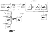
- FIG. 1 is a diagram showing an optical wavefront compensation device 100 according to a first embodiment of the present invention.
- the optical wavefront compensation device 100 includes a wavefront modulation unit 1, a light splitting unit 2, a projection target unit 3, a wavefront measurement unit 4, a target wavefront calculation unit 5, and a control unit 6.
- the control unit 6 includes a wavefront difference calculation unit 61 and a control signal calculation unit 62.
- the wavefront modulation unit 1 is an example of wavefront modulation means.
- the wavefront modulation unit 1 is a device that can spatially control the phase of light in a plurality of regions based on an external signal (in this embodiment, a wavefront modulation unit control signal from the control signal calculation unit 62), that is, an external This is a device capable of modulating the wavefront of the light beam based on the signal from.
- the wavefront modulation unit 1 is, for example, a deformable mirror or a liquid crystal panel.
- the wavefront modulation unit 1 modulates the wavefront of the light beam that has entered the optical wavefront compensation device 100 and fluctuates to generate a modulated light beam.
- the wavefront modulation unit 1 outputs the modulated light beam to the light splitting unit 2.
- the light dividing unit 2 is an example of a light dividing unit.
- the light splitting unit 2 splits the light beam into two or more light beams.
- the light splitting unit 2 is, for example, a half mirror, a prism, or a polarization beam splitter. Note that the intensity ratios of the divided light beams are not necessarily equal.
- the light splitting unit 2 splits the modulated light beam from the wavefront modulation unit 1 into a modulated light beam for the projection unit 3 and a modulated light beam for the wavefront measurement unit 4.
- the modulated light beam for the projection unit 3 is also referred to as “first modulated light beam”
- the modulated light beam for the wavefront measuring unit 4 is also referred to as “second modulated light beam”.
- the light splitting unit 2 irradiates the projection unit 3 with the first modulated light beam and irradiates the wavefront measuring unit 4 with the second modulated light beam.
- the projected unit 3 receives the first modulated light beam and operates using the first modulated light beam.
- various devices are used according to the system using the optical wavefront compensation device 100.
- the projection unit 3 collects a light beam (first modulated light beam) with a convex lens or a concave mirror and collects the light.
- a device that makes the emitted light incident on an optical fiber or a photoelectric conversion element is used.
- the coupling efficiency changes with the change of the wavefront of the light, so that the effect of wavefront compensation is great.
- the projection unit 3 collects a light beam by a convex lens or a concave mirror, and the workpiece is processed by the condensed light.
- a device that creates a spot on top is used.
- the size of the spot on the workpiece is the minimum processing dimension, and the energy density can be increased as the spot is smaller.
- the wavefront measuring unit 4 is an example of a wavefront measuring unit.
- the wavefront measuring unit 4 measures the spatial phase distribution of light (wavefront of light).
- the wavefront measuring unit 4 is, for example, a Shack-Hartmann wavefront sensor or a wavefront curvature sensor.
- the wavefront measuring unit 4 measures the wavefront of the second modulated light beam as the wavefront of the modulated light beam.
- the wavefront measurement unit 4 generates measurement wavefront information representing the measurement result of the wavefront of the modulated light beam, and outputs the measurement wavefront information to the wavefront difference calculation unit 61.
- the target wavefront calculation unit 5 is an example of target wavefront specifying means.
- the target wavefront calculation unit 5 generates target wavefront information representing the target wavefront that is the target of the wavefront of the modulated light beam.
- the target wavefront is a wavefront that allows the system using the optical wavefront compensation device 100 to achieve the desired performance. For example, a wavefront that has the smallest spot and ideally has a diffraction limit is used as the target wavefront.
- a target wavefront that is an initial value is set in the target wavefront calculator 5.
- the target wavefront calculator 5 changes the target wavefront information based on target wavefront calculation reference information (hereinafter referred to as “reference information”) for changing the target wavefront information.
- the reference information represents, for example, the light energy density on the projection surface.
- the control unit 6 is an example of a control unit.
- the control unit 6 Based on the measured wavefront information from the wavefront measuring unit 4 and the target wavefront information from the target wavefront calculating unit 5, the control unit 6 modulates the wavefront of the modulated light beam represented by the measured wavefront information and the target represented by the target wavefront information.
- the modulation in the wavefront modulation unit 1 is controlled so that the difference from the wavefront becomes small.
- the control unit 6 repeatedly executes the modulation control in the wavefront modulation unit 1.
- the wavefront difference calculation unit 61 calculates the difference between the target wavefront represented by the target wavefront information and the wavefront of the modulated light beam represented by the measured wavefront information, and generates wavefront difference information representing the difference.
- the wavefront difference calculation unit 61 outputs the wavefront difference information to the control signal calculation unit 62.
- the control signal calculation unit 62 calculates a wavefront modulation unit control signal based on the wavefront difference information from the wavefront difference calculation unit 61. This calculation is simply a feedback control calculation for controlling the modulation in the wavefront modulation unit 1 so that the difference represented by the wavefront difference information becomes small.
- the control signal calculation unit 62 applies a conversion matrix when calculating the wavefront modulation unit control signal, etc. The conversion operation is also performed.
- FIG. 2 is a process flowchart for explaining the process until the operation of the system incorporating the optical wavefront compensation apparatus 100 is started.
- a system incorporating the optical wavefront compensation device 100 is manufactured (step S201), and then the system incorporating the optical wavefront compensation device 100 is transported and installed (step S202).
- step S203 Calibration searches for the most desirable wavefront state for the system.
- calibration may be performed after transportation before installation as long as there is no impact or distortion in the optical wavefront compensation device 100 to such an extent that the wavefront is greatly affected by the installation work.
- the wavefront compensation device 100 is not shocked or distorted to such an extent that the wavefront is greatly affected by the transportation / installation work, calibration may be performed after the manufacture before the transportation / installation.
- this wavefront is set in the target wavefront computing unit 5 as the first target wavefront (step S204).
- the optical wavefront compensation device 100 is operated (step S205).
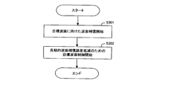
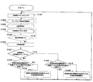
- FIG. 3 is a flowchart for explaining the operation of the optical wavefront compensation apparatus 100.
- the optical wavefront compensation device 100 performs wavefront compensation toward the set target wavefront (step S301), and controls the target wavefront based on the reference information in order to reduce the long-term wavefront compensation error (step S302). .
- step S301 will be described.
- the light beam having a swayed wavefront incident on the optical wavefront compensation device 100 is subjected to wavefront modulation by the wavefront modulation unit 1, and then the optical path is divided by the light dividing unit 2.
- One of the divided lights (second modulated light beam) enters the wavefront measuring unit 4.
- the wavefront measuring unit 4 measures the wavefront of the light beam (second modulated light beam) incident on the wavefront measuring unit 4, and passes the measured wavefront information representing the measurement result to the wavefront difference calculating unit 61.
- the wavefront difference calculating unit 61 calculates a difference between the target wavefront set by the target wavefront calculating unit 5 and the wavefront measured by the wavefront measuring unit 4, and uses the control signal calculating unit 62 as the wavefront difference information representing the difference. Hand over to.
- the control signal calculation unit 62 calculates a wavefront modulation unit control signal from the wavefront difference information, and controls the wavefront modulation unit 1 using the wavefront modulation unit control signal.
- the control signal calculation unit 62 feedback-controls the wavefront modulation unit 1 so that the difference between the target wavefront and the measurement wavefront is small, thereby changing the light beam (modulated light beam) that has passed through the wavefront modulation unit 1 to a desired light beam. And compensate.
- the light beam (first modulated light beam) on the other optical path divided by the light splitting unit 2 enters the projection target unit 3.
- the projected part 3 operates using the incident light beam (first modulated light beam).
- the wavefront of the light beam incident on the optical wavefront compensation device 100 is fluctuated by compensating the wavefront of the light beam (modulated light beam)
- a system having the optical wavefront compensation device 100 is desired. Performance can be achieved.
- step S302 will be described.
- step S302 the target wavefront calculator 5 controls the target wavefront based on the reference information in order to reduce the long-term wavefront compensation error.
- the wavefront modulation unit 1 modulates the wavefront of the light beam to generate a modulated light beam.
- the wavefront measuring unit 4 measures the wavefront of the modulated light beam.
- the target wavefront calculation unit 5 generates a target wavefront that is the target of the wavefront of the modulated light beam.
- the control unit 6 controls the modulation in the wavefront modulation unit 1 so that the difference between the measurement result of the wavefront measurement unit 4 and the target wavefront becomes small.
- the target wavefront calculator 5 changes the target wavefront based on the reference information for changing the target wavefront.
- the target wavefront can be changed during the operation of the optical wavefront compensation apparatus 100. Therefore, even if a long-term wavefront compensation error occurs, the target wavefront can be corrected without stopping the optical wavefront compensation device 100, and the optical wavefront compensation device 100 is stable for a long time without stopping. It becomes possible to achieve the operation.
- a system to which the optical wavefront compensation device is applied is a communication system
- the projected portion 3 has a convex lens 31, an optical fiber 32, and a light as shown in FIG. It is composed of an electrical conversion element 33, light is incident on the optical fiber 32 by the convex lens 31, and the light guided through the optical fiber 32 is converted to an electrical signal (measurement result of the light beam) by the photoelectric conversion element 33.
- a description will be given of a system in which a signal is output to the communication apparatus 200. However, this does not limit the applicable configuration to the communication system, and does not limit the configuration of the projected part 3 to that shown in FIG.
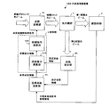
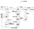
- FIG. 5 is a diagram showing an optical wavefront compensation device 100A according to the second embodiment of the present invention.
- the same components as those shown in FIG. 5 are shown in FIG. 5;
- the optical wavefront compensation device 100A of the second embodiment includes a wavefront modulation unit 1, a wavefront measurement unit 4, a target wavefront calculation unit 5, a wavefront difference calculation unit 61, and a control signal calculation unit 62 shown in FIG. 1A, wavefront measuring unit 4A, target wavefront calculating unit 5A, wavefront difference calculating unit 61A, and control signal calculating unit 62A are used. Information that functions as reference information is used by the projected unit 3 and the wavefront measuring unit 4A. The point which outputs to the calculating part 5A differs from the optical wavefront compensation apparatus 100 of 1st Embodiment.
- optical wavefront compensation device 100A of the second embodiment will be described focusing on differences from the optical wavefront compensation device 100 of the first embodiment.
- the wavefront measuring unit 4A uses the magnitude of the mode coefficient when fitting the wavefront as a superposition of a plurality of specific shapes (modes) as the measurement wavefront information, and calculates the wavefront difference calculating unit 61A and the target wavefront calculation.
- the measured wavefront information output to the target wavefront calculator 5A functions as reference information.
- the mode coefficient of each mode constitutes a plurality of parameters of the measurement wavefront information.
- the target wavefront computing unit 5A outputs target wavefront information having a mode coefficient in each mode used by the wavefront measuring unit 4A as a plurality of parameters.
- the wavefront difference calculation unit 61A calculates a difference in mode coefficient value for each mode based on the measured wavefront information from the wavefront measurement unit 4A and the target wavefront information from the target wavefront calculation unit 5A, and the difference between the mode coefficient values. Is output.
- the control signal calculation unit 62A adjusts the wavefront modulation unit control signal according to the difference of each mode coefficient value represented by the wavefront difference information from the wavefront difference calculation unit 61A.
- the wavefront modulation unit control signal has a mode coefficient in each mode as a parameter.
- the wavefront modulation unit 1A controls the modulation of the light beam according to each mode coefficient value in the wavefront modulation unit control signal. For each mode coefficient in the wavefront modulation unit control signal, the wavefront modulation unit 1A modulates the light beam so that the mode in the modulated light beam increases as the value of the mode coefficient increases.
- the control signal calculation unit 62A sets the mode coefficient value in the wavefront modulation unit control signal so that the difference between the mode coefficient values represented by the wavefront difference information becomes smaller according to the difference between the mode coefficient values represented by the wavefront difference information. change.
- the horizontal axis is the mode coefficient and the vertical axis is the light intensity
- the relationship between the mode coefficient and the light intensity in each mode is a distribution having at least one maximum point. It becomes.
- the photoelectric conversion element 33 outputs light intensity information indicating the intensity of light incident on the optical fiber 32, which is an optical system, to the target wavefront calculation unit 5A as reference information.
- the light intensity information is an example of the measurement result of the light beam by the photoelectric conversion element 33, and represents, for example, the degree of energy density of the light beam.
- the target wavefront calculator 5A performs sampling, storage, and statistical evaluation using the measured wavefront information and the light intensity information as time series data, and corrects the target wavefront according to the evaluation.
- the wavefront fluctuation of the light beam incident on the optical wavefront compensation device 100A has a frequency characteristic determined by an external factor, whereas the optical wavefront compensation device 100A performs feedback control (the wavefront measurement unit 4A, the control unit 6, and the wavefront modulation unit 1A). Control performed by and).
- the target wavefront calculator 5A obtains the measurement wavefront information and the light intensity information for a measurement period sufficiently longer than the wavefront fluctuation period assumed from the frequency characteristics determined by external factors (for example, a period five times the wavefront fluctuation period). After acquisition, statistical evaluation is performed on the acquired measurement wavefront information and light intensity information.
- the measurement period is not limited to five times the wavefront fluctuation period and can be changed as appropriate.
- the optical wavefront compensation device 100A is always in a feedback control toward the target wavefront, but the light beam incident on the optical wavefront compensation device 100A has a fluctuating wavefront, so even if feedback control is performed, Certain fluctuations remain.
- each mode coefficient and the light intensity is a distribution having at least one maximum point, and it is assumed that the target wavefront is at the optimum point at the start of operation by calibration before the operation of the optical wavefront compensation device 100A.
- the distribution usually has one maximum point.
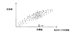
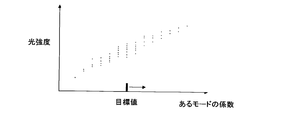
- FIG. 6 is a plot of coefficients of a certain mode (hereinafter referred to as “mode a”) and light intensity information at that time.
- the target value of the mode coefficient for mode a and the optimum value of the mode coefficient for mode a (when the light intensity reaches a maximum value in mode a) Mode coefficient values) match or substantially match.
- the target wavefront calculation unit 5A performs control to change the target value of the mode coefficient so that the light intensity becomes higher with respect to the mode in which such a phenomenon occurs.
- the target wavefront calculation unit 5A applies an appropriate gain to the mode coefficient value.
- the target value of the mode coefficient may be changed in the direction of higher intensity.
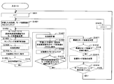
- FIG. 8 is a flowchart for explaining the processing of the target wavefront computing unit 5A.
- n is a variable representing the type of mode, and is provided in the target wavefront computing unit 5A, for example. Further, the target wavefront computing unit 5A has a memory for storing the sampling results of the measured wavefront information and the light intensity information.
- the target wavefront calculator 5A clears the measurement information (measurement wavefront information and light intensity information) in the memory (step S802).
- the target wavefront calculation unit 5A samples (acquires) the measurement wavefront information from the wavefront measurement unit 4A and the light intensity information from the projection unit 3 (step S804). ). Note that the measured wavefront information from the wavefront measuring unit 4A indicates the mode coefficient value of each mode.
- the target wavefront computing unit 5A stores the sampling result (measured wavefront information and light intensity information) in the memory (step S805).
- the target wavefront computing unit 5A determines whether or not the elapsed time since the execution of Step S802 has exceeded a preset measurement time (for example, a period five times the wavefront fluctuation period) (Step S806). .
- a preset measurement time for example, a period five times the wavefront fluctuation period
- step S802 If the elapsed time after executing step S802 does not exceed the measurement time, the target wavefront computing unit 5A returns the process to step S803.
- the target wavefront calculation unit 5A statistically evaluates the relationship between the light intensity and the mode coefficient for mode n as shown in FIGS. Then, the optimum value of the mode coefficient for mode n (the mode coefficient value when the light intensity reaches the maximum value in mode n) is calculated (step S807).
- the target wavefront computing unit 5A determines whether there is a significant difference between the current target value of the mode coefficient and the optimal value of the mode coefficient calculated in step S807 (step S808).
- the significant difference is, for example, a difference within a previously assumed range.
- the target wavefront computing unit 5A changes the target value of the mode coefficient for mode n to the optimal value of the mode coefficient calculated in step S807 (step S809).
- the target wavefront calculation unit 5A changes the target wavefront according to the target value after the change of the mode coefficient for mode n, and outputs target wavefront information representing the changed target wavefront to the wavefront difference calculation unit 61A. (Step S810).
- the target wavefront calculator 5A determines whether the determination has been completed for all modes (step S811). For example, if the variable n indicates the total number of modes, the target wavefront calculation unit 5A determines that the determination has been completed for all modes, and if the variable n does not indicate the total number of modes, determines for all modes. Is determined not to end.
- step S812 If the determination has not been completed for all modes, the target wavefront computing unit 5A adds 1 to the variable n (step S812), and the process returns to step S802.
- the target wavefront computing unit 5A returns the process to step S801.
- step S808 If there is no significant difference in step S808, the target wavefront computing unit 5A returns the process to step S811.
- each mode to be adjusted is determined one by one in order.
- each loop is determined.
- the control unit 6 repeatedly executes the modulation control in the wavefront modulation unit 1A, and the target wavefront calculation unit 5A has the time for the control unit 6 to execute the modulation control in the wavefront modulation unit 1A.
- the target wavefront is changed based on the reference information at a time interval longer than the interval.
- the light splitting unit 2 splits the modulated light beam into a first modulated light beam and a second modulated light beam
- the first modulated light beam is a convex lens 31 and an optical fiber which are an example of an optical system.
- 32 is irradiated.
- the photoelectric conversion element 33 which is an example of the light beam measuring unit and the intensity measuring unit measures the light beam that has entered the optical fiber 32 out of the first modulated light beam.
- the wavefront measuring unit 4A measures the wavefront of the second modulated light beam as the wavefront of the modulated light beam.
- the target wavefront calculator 5A uses the measurement result of the wavefront measurement unit 4A and the measurement result of the photoelectric conversion element 33 as reference information.
- the target wavefront is changed based on the relationship between the wavefront of the modulated light beam and the intensity (energy density) of the light that has entered the optical fiber 32 of the modulated light beam (first modulated light beam). Is possible. Therefore, even if a long-term wavefront compensation error occurs, the target wavefront can be corrected without stopping the optical wavefront compensation device 100A.
- the target wavefront has a mode coefficient for each mode as a plurality of parameters.
- the target wavefront calculation unit 5A specifies a target value (optimum value) of the mode coefficient based on the measurement result of the wavefront measurement unit 4A and the measurement result of the photoelectric conversion element 33 for each mode coefficient of each mode, The mode coefficient value of the target wavefront is changed according to the target value (optimum value), and the target wavefront having the changed mode coefficient value is output to the control unit 6.
- the target wavefront can be changed in units of mode coefficients.
- the target wavefront computing unit 5A sets the value of the mode coefficient in the measured wavefront information when the light intensity represented by the light intensity information becomes maximum within the measurement period (predetermined period) for each mode coefficient. Is specified as the target value of the mode coefficient.
- FIG. 9 is a diagram showing an optical wavefront compensation device 100B according to the third embodiment of the present invention.
- the same components as those shown in FIG. 9 are identical to those shown in FIG. 9;
- the optical wavefront compensation device 100B of the third embodiment is different from the optical wavefront compensation device 100A of the second embodiment in that the target wavefront calculation unit 5B is used instead of the target wavefront calculation unit 5A shown in FIG. .
- the target wavefront calculator 5B collectively changes the mode coefficient values of a plurality of modes in the target wavefront information.
- the wavefront measuring unit 4A can analyze the measurement data and measure the mode coefficient (mode coefficient value) of each mode. For this reason, the wavefront measuring unit 4A may change the mode coefficient values of a plurality of modes for one measurement.
- FIG. 10 is a flowchart for explaining the processing of the target wavefront computing unit 5B in the third embodiment.
- the same processes as those shown in FIG. 8 are denoted by the same reference numerals.
- the processing of the target wavefront calculation unit 5B will be described with a focus on differences from the processing shown in FIG.
- the target wavefront calculator 5B performs measurement.
- the target wavefront calculation unit 5B samples light intensity information from the projection target unit 3 (photoelectric conversion element 33) and measurement wavefront information from the wavefront measurement unit 4A at predetermined sampling periods (step S803). (Acquire) (step S804), and the sampled light intensity information and the measured wavefront information are paired and stored on the memory (step S805).
- the target wavefront calculator 5B repeats steps S803 to S805 during the measurement period, and ends the measurement when the measurement period elapses (step S806).
- the target wavefront calculator 5B evaluates the measured value.
- the target wavefront calculation unit 5B executes step S801 in the evaluation of the measured value, and then executes steps S807, S808, S809, S811, and S812. If there is no significant difference in step S808, step S811 is executed after step S808.
- the target wavefront calculation unit 5B has a significant difference between the target value of the mode coefficient currently set and the optimal value of the mode coefficient calculated in step S807 for each mode for all modes to be adjusted. If there is a significant difference, the target value of the mode coefficient is changed to the optimal value of the mode coefficient.
- the target wavefront calculation unit 5B changes the current target wavefront according to the changed target value of the mode coefficient for each mode (step S810), and calculates the wavefront difference calculation for the target wavefront information representing the changed target wavefront.
- the data is output to the unit 61A (step S1001).
- the target wavefront calculation unit 5B deletes (clears) the measurement information in the memory (step S802).
- the target wavefront calculation unit 5B specifies the target value (optimum value) of the mode coefficient for each mode coefficient based on the measurement result of the wavefront measurement unit 4A and the measurement result of the photoelectric conversion element 33. Then, the value of each mode coefficient of the target wavefront is changed according to the target value (optimum value) of the mode coefficient, and the target wavefront in which the value of each mode coefficient is changed is output to the control unit 6.
- the time required for the search is shortened, so that a long-term wavefront compensation error can be dealt with quickly. Is possible.
- the target wavefront calculator 5B for each mode coefficient, sets the value of the mode coefficient in the measured wavefront information when the light intensity represented by the light intensity information becomes maximum within the measurement period (predetermined period). Is specified as the target value of the mode coefficient.
- FIG. 11 is a diagram showing an optical wavefront compensation device 100C according to the fourth embodiment of the present invention.
- the same components as those shown in FIG. 11 are shown in FIG. 11;
- the optical wavefront compensation apparatus 100C of the fourth embodiment uses a target wavefront calculation unit 5C and a control signal calculation unit 62C instead of the target wavefront calculation unit 5A and the control signal calculation unit 62A shown in FIG.
- Projected portion 3 (photoelectric conversion element 33) outputs functioning light intensity information to target wavefront computing portion 5C, and a search wavefront modulation signal generating portion (hereinafter referred to as “generating portion”) 7 is added.
- generating portion search wavefront modulation signal generating portion
- optical wavefront compensation device 100C of the fourth embodiment will be described focusing on differences from the optical wavefront compensation device 100A of the second embodiment.
- the target wavefront computing unit 5C outputs target wavefront information having a mode coefficient in each mode used by the wavefront measuring unit 4A as a plurality of parameters.
- the control signal calculation unit 62C adjusts the wavefront modulation unit control signal according to the difference of each mode coefficient value represented by the wavefront difference information from the wavefront difference calculation unit 61A, similarly to the control signal calculation unit 62A.
- the wavefront modulation unit control signal has a mode coefficient in each mode as a parameter.
- the control signal calculation unit 62C sets the mode coefficient value in the wavefront modulation unit control signal so that the difference between the mode coefficient values represented by the wavefront difference information becomes small according to the difference between the mode coefficient values represented by the wavefront difference information. change.
- the search wavefront modulation signal output from the generator 7 and the light intensity information from the photoelectric conversion element 33 are input to the target wavefront calculator 5C as reference information.
- the search wavefront modulation signal has a specific period sufficiently longer than the wavefront fluctuation period assumed from the frequency characteristics of the wavefront fluctuation of the light beam incident on the optical wavefront compensation apparatus 100C (for example, a period of 10 times the wavefront fluctuation period). Modulate with.
- the specific period is not limited to 10 times the wavefront fluctuation period and can be changed as appropriate.
- the search wavefront modulation signal has a mode coefficient of a certain mode as a parameter.
- the generation unit 7 sequentially changes the mode coefficient value in the search wavefront modulation signal and sequentially changes the mode in the search wavefront modulation signal.
- the generation unit 7 sequentially changes the value of the mode coefficient of the measurement target among the plurality of mode coefficients, and then switches the mode coefficient of the measurement target to another mode coefficient in the same manner.
- the operation of sequentially changing the value of is executed. Therefore, at each time, the search wavefront modulation signal shows only a value for one mode coefficient.
- the control signal calculation unit 62C for the mode coefficients represented by the search wavefront modulation signal, among the mode coefficients of the wavefront modulation unit control signal, the mode represented by the search wavefront modulation signal represents the value of the mode coefficient of the wavefront modulation unit control signal. Add to the coefficient value.
- the wavefront modulation unit control signal in which the mode coefficient value is changed is an example of the change control signal.
- the search wavefront modulation is performed in the modulated light beam from the wavefront modulation unit 1A.
- a mode corresponding to the mode coefficient indicated in the signal is modulated according to the search wavefront modulation signal.
- the target wavefront computing unit 5C samples, stores, and statistically evaluates the wavefront modulation signal for search and the light intensity information when the wavefront modulation signal for search is output as time-series data. The target wavefront is corrected accordingly.
- the search wavefront modulation signal generated by the generation unit 7 is changed at a specific period sufficiently longer than the wavefront fluctuation period assumed from the frequency characteristics of the wavefront fluctuation of the light beam incident on the optical wavefront compensation apparatus 100C.
- the wavefront calculation unit 5C acquires and evaluates the light intensity at this time from the projection target unit 3 (the photoelectric conversion element 33).
- an evaluation method for example, a method of taking an average value of light intensity or a method of taking a median value of light intensity.
- the horizontal axis is the mode coefficient and the vertical axis is the light intensity
- the relationship between the mode coefficient and the light intensity in each mode is at least one local maximum point.
- the measurement is performed in a state where feedback is performed toward a predetermined target that is correct to some extent, so the range of values in the measured mode coefficient (change of the value of the mode coefficient in the wavefront modulation signal for search) In the range), the distribution usually has one maximum point.
- FIG. 12 is a plot of the value of the mode coefficient of a certain mode and the light intensity information measured when the wavefront modulation signal for search represents the value of the mode coefficient of that mode.
- the light intensity may not be a peak when the value of the mode coefficient currently set as the target is reached.
- the target wavefront calculation unit 5C performs control to change the target value of the mode coefficient so that the light intensity becomes higher with respect to the mode in which such a phenomenon occurs.
- the target wavefront calculation unit 5C applies an appropriate gain to the mode coefficient value.
- the target value of the mode coefficient may be changed in the direction of higher strength.
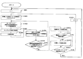
- FIG. 14 is a flowchart for explaining the processing of the target wavefront computing unit 5C.
- the same processes as those shown in FIG. 8 are denoted by the same reference numerals.
- the target wavefront calculator 5C clears the information (evaluated light intensity and mode coefficient value) in the memory of the target wavefront calculator 5C (step S1401).
- the target wavefront calculator 5C outputs a change instruction to the generator 7 to change the value of the mode coefficient for the mode n of the search wavefront modulation signal.
- the generation unit 7 changes the value of the mode coefficient for the mode n of the search wavefront modulation signal in accordance with the change instruction (step S1402).
- the generation unit 7 outputs the search wavefront modulation signal in which the value of the mode coefficient for the mode n is changed to the control signal calculation unit 62C and the target wavefront calculation unit 5C.
- the control signal calculation unit 62C When receiving the search wavefront modulation signal, the control signal calculation unit 62C adds the mode coefficient value of the mode n of the wavefront modulation unit control signal to the value of the mode coefficient for the mode n of the search wavefront modulation signal, The wavefront modulation unit control signal is changed, and the modulation in the wavefront modulation unit 1A is controlled using the changed wavefront modulation unit control signal (change control signal).
- the target wavefront computing unit 5C samples (acquires) light intensity information from the projection target unit 3 when the sampling period T elapses (step S1403) (step S1404).
- the sampled light intensity information comes from the modulated light beam whose modulation is controlled by the changed wavefront modulation unit control signal.
- the target wavefront calculation unit 5C stores the sampling result (light intensity information) in the memory (step S1405).
- the target wavefront computing unit 5C determines whether the elapsed time after executing Step S1402 has exceeded a preset measurement time (Step S1406).
- step S1402 If the elapsed time since the execution of step S1402 does not exceed the measurement time, the target wavefront computing unit 5C returns the process to step S1403.
- step S1402 when the elapsed time after executing step S1402 exceeds the measurement time, the target wavefront computing unit 5C evaluates each of the light intensity information stored in step S1405 (step S1407).
- the target wavefront calculation unit 5C statistically evaluates the light intensity information, for example, calculates an average value, for each mode coefficient value represented by the search wavefront modulation signal.
- the target wavefront computing unit 5C makes a pair of the evaluated light intensity value information (for example, average value) and the mode coefficient value of the mode represented by the search wavefront modulation signal, and stores them in the memory (step S1408). ).
- the evaluated light intensity value information for example, average value
- the mode coefficient value of the mode represented by the search wavefront modulation signal stores them in the memory (step S1408).
- the target wavefront computing unit 5C clears the light intensity information stored in step S1405 from the memory (step S1409).
- the target wavefront computing unit 5C determines whether or not the range for changing the mode coefficient of the mode n represented by the search wavefront modulation signal has ended (step S1410). This range is preset in the target wavefront calculator 5C.
- the target wavefront computing unit 5C returns the process to step S1402.
- the target wavefront calculator 5C changes the relationship between the light intensity and the mode coefficient as shown in FIGS.
- Statistical evaluation is performed to calculate the optimum value of the mode coefficient (the mode coefficient value when the light intensity reaches the maximum value in mode n) (step S1411).
- the target wavefront calculation unit 5C determines whether there is a significant difference between the current mode coefficient target value and the optimal value of the mode coefficient calculated in step S1411 for mode n (step S1412). .
- the target wavefront calculator 5C changes the target value of the mode coefficient of mode n to the optimal value of the mode coefficient calculated in step S1411, and changes the current target wavefront to the mode for mode n.
- the target wavefront information representing the target wavefront after the change is output to the wavefront difference calculation unit 61A (step S1413).
- the target wavefront calculator 5C determines whether the determination has been completed for all modes (step S1414). For example, if the variable n indicates the total number of modes, the target wavefront calculation unit 5C determines that the determination has been completed for all modes, and if the variable n does not indicate the total number of modes, determines for all modes. Is determined not to end.
- the target wavefront computing unit 5C adds 1 to the variable n (step S1415), and then returns the process to step S1401.
- the target wavefront computing unit 5C returns the process to step S801.
- step S1412 If there is no significant difference in step S1412, the target wavefront computing unit 5C advances the process to step S1414.
- each mode to be adjusted is determined one by one in order.
- each loop is determined.
- the generation unit 7 generates a wavefront modulation signal for search in which the value of the mode coefficient is sequentially changed and the mode coefficient is sequentially changed for any one of the plurality of mode coefficients.
- the control unit 6 generates a wavefront modulation unit control signal for controlling the modulation in the wavefront modulation unit 1A so that the difference between the measurement result (measurement wavefront information) of the wavefront measurement unit 4A and the target wavefront is small, and the wavefront modulation unit
- the control signal is changed based on the search wavefront modulation signal, and the modulation in the wavefront modulation unit 1A is controlled using the changed wavefront modulation unit control signal.
- the target wavefront calculation unit 5C uses the search wavefront modulation signal from the generation unit 7 and the light intensity information from the photoelectric conversion element 33 as reference information.
- the wavefront fluctuation of the light beam incident on the optical wavefront compensation device is small, or the fluctuation of the wavefront after the wavefront modulation unit 1A with sufficient feedback control functioning. Even in a small state, the long-term wavefront compensation error can be actively reduced.
- the control unit 6 searches for the value of the mode coefficient in the wavefront modulation unit control signal for the mode coefficient represented by the search wavefront modulation signal among the mode coefficients in the wavefront modulation unit control signal.
- the mode coefficient value represented by the wavefront modulation signal is changed.
- the target wavefront calculation unit 5C determines the value of the mode coefficient represented by the search wavefront modulation signal when the light intensity represented by the light intensity information becomes maximum within the measurement time (predetermined period). Specify as the target value.
- the generation unit 7 changes the value of the mode coefficient in the search wavefront modulation signal with a period longer than the assumed fluctuation period of the light beam to the optical wavefront compensation apparatus 100C.
- the modulation in the wavefront modulation unit 1A accompanying the change of the value of the mode coefficient in the wavefront modulation signal for search can be made less susceptible to the influence of the fluctuation of the light beam on the optical wavefront compensation device 100C.
- FIG. 15 is a diagram showing an optical wavefront compensation device 100D according to the fifth embodiment of the present invention.
- the same components as those shown in FIG. 11 are denoted by the same reference numerals.
- the target wavefront calculation unit 5D and the control signal calculation unit 62A are used instead of the target wavefront calculation unit 5C and the control signal calculation unit 62C.
- the point which the part 8 is inserted and the wavefront modulation part 9 and the to-be-projected part 10 are added differs from 4th Embodiment.
- the projected part 10 has the same configuration as the projected part 3.
- optical wavefront compensation device 100D of the fifth embodiment will be described focusing on differences from the optical wavefront compensation device 100C of the fourth embodiment.
- the light splitting units 2 and 8 are included in the splitting unit 11.
- the dividing unit 11 is an example of a light dividing unit.
- the dividing unit 11 divides the modulated light beam into a modulated light beam for the projection unit 3, a modulated light beam for the wavefront measuring unit 4A, and a modulated light beam for the wavefront modulating unit 9.
- the modulated light beam for the projection unit 3 is also referred to as “first modulated light beam”
- the modulated light beam for the wavefront measuring unit 4A is also referred to as “second modulated light beam”
- the modulated light for the wavefront modulator 9 is used.
- the beam is also referred to as a “third modulated light beam”.
- the light dividing unit 8 divides the light beam from the light dividing unit 2 into a modulated light beam for the projection target unit 3 and a modulated light beam for the wavefront modulation unit 9.
- the light dividing unit 8 irradiates the projection unit 3 (specifically, the first optical system including the convex lens 31 and the optical fiber 32 in the projection unit 3) with the modulated light beam for the projection unit 3.
- the modulated light beam for the wavefront modulation unit 9 is irradiated to the wavefront modulation unit 9.
- the wavefront modulation unit 9 is an example of modulation means.
- the wavefront modulation unit 9 has the same configuration as the wavefront modulation unit 1A.
- the wavefront modulation unit 9 generates a fourth modulated light beam by modulating the wavefront of the modulated light beam for the wavefront modulation unit 9 based on the wavefront modulation signal for search, and generates the fourth modulated light beam as the projection unit 10. (Specifically, the second optical system including the convex lens 31 and the optical fiber 32 in the projection target 10) is irradiated.
- the photoelectric conversion element 33 in the projection target 10 is an example of an intensity measuring unit.
- the photoelectric conversion element 33 in the projection unit 10 measures the intensity of the light beam that has entered the optical fiber 32 in the projection unit 10 out of the fourth modulated light beam.
- the target wavefront calculation unit 5D outputs target wavefront information having a mode coefficient in each mode used by the wavefront measurement unit 4A as a plurality of parameters.
- the search wavefront modulation signal output from the generator 7 and the light intensity information from the photoelectric conversion element 33 in the projection target 10 are input to the target wavefront calculator 5D as reference information.
- the search wavefront modulation signal has a specific period sufficiently longer than the wavefront fluctuation period assumed from the frequency characteristics of the wavefront fluctuation of the light beam incident on the optical wavefront compensation device 100D (for example, a period of 10 times the wavefront fluctuation period). Modulate with.
- the specific period is not limited to 10 times the wavefront fluctuation period and can be changed as appropriate.
- the target wavefront computing unit 5D samples, stores, and statistically evaluates the wavefront modulation signal for search and the light intensity information when the wavefront modulation signal for search is output as time-series data. The target wavefront is corrected accordingly.
- the statistical evaluation method in the target wavefront calculation unit 5D is the same as the statistical evaluation method in the target wavefront calculation unit 5C.
- the optical path that continues from the light splitting unit 8 to the wavefront modulation unit 9 and the projection target unit 10 is a different optical path from the light beam that is desired to be used as a system, and is for reducing long-term wavefront compensation errors. It is.
- the dividing unit 11 divides the modulated light beam into a modulated light beam for the projection target unit 3, a modulated light beam for the wavefront measuring unit 4A, a modulated light beam for the wavefront modulation unit 9, and Divide into
- the wavefront modulation unit 9 modulates the wavefront of the modulated light beam for the wavefront modulation unit 9 based on the search wavefront modulation signal from the generation unit 7 to generate a fourth modulated light beam, and the fourth modulated light beam Irradiates the projection unit 10.
- the photoelectric conversion element 33 in the projection unit 10 measures the intensity of the light beam that has entered the optical fiber 32 in the projection unit 10 out of the fourth modulated light beam.
- the target wavefront calculation unit 5D uses the search wavefront modulation signal from the generation unit 7 and the light intensity information from the photoelectric conversion element 33 in the projection target unit 10 as reference information.
- the wavefront fluctuation of the light beam incident on the optical wavefront compensation device is small, or the fluctuation of the wavefront after the wavefront modulation unit 1A with sufficient feedback control functioning. Even in a small state, the long-term wavefront compensation error can be actively reduced.
- the search may cause the light intensity incident on the optical fiber 32 in the projection target 3 to be changed, which may cause an influence on the system.
- the search for reducing the target wavefront error is performed in an optical path different from that used in the system. For this reason, it is possible to prevent the light intensity that is incident on the optical fiber 32 in the projected portion 3 from being varied by searching, and the possibility that the influence on the system is generated can be reduced.
- the target wavefront computing unit 5D for each mode coefficient, represents the mode coefficient represented by the search wavefront modulation signal when the light intensity represented by the light intensity information becomes maximum within the measurement time (predetermined period). Is specified as the target value of the mode coefficient.
- FIG. 16 is a diagram showing an optical wavefront compensation device 100E according to the sixth embodiment of the present invention.
- the same components as those shown in FIG. 15 are denoted by the same reference numerals.
- the light wavefront compensation device 100E of the sixth embodiment is that the light dividing unit 8 is omitted, the light dividing unit 12 is added, and the optical path to the wavefront modulating unit 9 and the projection target part 10 is changed. Different from the embodiment.
- the light wavefront compensation device 100E of the sixth embodiment will be described focusing on differences from the light wavefront compensation device 100D of the fifth embodiment.
- the light splitting unit 12 is an example of a first light splitting unit.
- the light splitting unit 12 splits the light beam incident on the optical wavefront compensation device 100E into a light beam for the wavefront modulation unit 1A and a light beam for the wavefront modulation unit 9.
- the light beam for the wavefront modulation unit 1A is an example of a first light beam
- the light beam for the wavefront modulation unit 9 is an example of a second light beam.
- the light splitting unit 12 irradiates the wavefront modulation unit 1A with the light beam for the wavefront modulation unit 1A as a light beam incident on the optical wavefront compensation device 100E, and the light beam for the wavefront modulation unit 9 with the wavefront modulation unit 9 Irradiate.
- the wavefront modulation unit 9 modulates the wavefront of the light beam for the wavefront modulation unit 9 based on the search wavefront modulation signal to generate a reference modulated light beam.
- the wavefront modulation unit 9 irradiates the projection target unit 10 (specifically, the second optical system including the convex lens 31 and the optical fiber 32 in the projection unit 10) with the reference modulated light beam.
- the photoelectric conversion element 33 in the projection unit 10 measures the intensity of the light beam that has entered the optical fiber 32 in the projection unit 10 out of the reference modulated light beam.
- the optical path that continues from the light splitting unit 12 to the wavefront modulation unit 9 and the projection target unit 10 is a different optical path from the light beam that is desired to be used as a system, and is intended to reduce long-term wavefront compensation errors. It is.
- the light splitting unit 12 splits the light beam incident on the optical wavefront compensation device 100E into a light beam for the wavefront modulation unit 1A and a light beam for the wavefront modulation unit 9.
- the wavefront modulation unit 9 modulates the wavefront of the light beam for the wavefront modulation unit 9 based on the search wavefront modulation signal to generate a reference modulated light beam.
- the wavefront modulation unit 9 irradiates the projection target unit 10 (specifically, the second optical system including the convex lens 31 and the optical fiber 32 in the projection unit 10) with the reference modulated light beam.
- the photoelectric conversion element 33 in the projection unit 10 measures the intensity of the light beam that has entered the optical fiber 32 in the projection unit 10 out of the reference modulated light beam.
- the target wavefront calculation unit 5D uses the search wavefront modulation signal from the generation unit 7 and the light intensity information from the photoelectric conversion element 33 in the projection target unit 10 as reference information.
- the seventh embodiment is different from the fourth to sixth embodiments in the operation of the generation unit 7.
- the generation unit 7 in the seventh embodiment generates a search wavefront modulation signal having a frequency that is faster (sufficiently faster) than the fluctuation frequency assumed from the frequency characteristics of wavefront fluctuation of the light beam incident on the optical wavefront compensation device.
- the incident light beam can be regarded as constant while the wavefront modulation signal for search is changing. Therefore, in the third to sixth embodiments, the light intensity that needs to be statistically evaluated need not be statistically evaluated, and only a representative value may be taken.
- FIG. 17 is a flowchart for explaining the processing of the target wavefront computing unit in the fourth to sixth embodiments when the generating unit 7 in the seventh embodiment is used.
- the same processes as those shown in FIG. 14 are denoted by the same reference numerals.
- the target wavefront calculator clears the information (evaluated light intensity and mode coefficient value) in the memory of the target wavefront calculator 5C (step S1401).
- the target wavefront calculator outputs a change instruction to the generator 7 to change the value of the mode coefficient for the mode n of the search wavefront modulation signal.
- the generation unit 7 changes the value of the mode coefficient for the mode n of the search wavefront modulation signal in accordance with the change instruction (step S1402).
- the generation unit 7 outputs the search wavefront modulation signal in which the value of the mode coefficient for the mode n is changed.
- the target wavefront calculation unit samples (acquires) the light intensity information when the sampling period T elapses (step S1403) (step S1404).
- the target wavefront calculation unit makes a pair of the acquired light intensity value information and the mode coefficient value of the mode represented by the search wavefront modulation signal, and stores them in the memory (step S1701).
- the target wavefront calculation unit determines whether or not the range for changing the mode coefficient of the mode n represented by the search wavefront modulation signal has ended (step S1410).
- the target wavefront computing unit returns the process to step S1402.
- the target wavefront calculator calculates the relationship between the light intensity and the mode coefficient as shown in FIGS. Evaluation is performed to calculate the optimum value of the mode coefficient (the mode coefficient value when the light intensity reaches the maximum value in mode n) (step S1411).
- the target wavefront calculation unit determines whether there is a significant difference between the target value of the current mode coefficient and the optimal value of the mode coefficient calculated in step S1411 (step S1412).
- the target wavefront computing unit changes the target value of the mode coefficient of mode n to the optimal value of the mode coefficient calculated in step S1411 and changes the current target wavefront to the mode coefficient for mode n.
- the target wavefront information representing the target wavefront after the change is output to the wavefront difference calculation unit 61A (step S1413).
- the target wavefront calculation unit determines whether the determination has been completed for all modes (step S1414).
- the target wavefront computing unit adds 1 to the variable n (step S1415), and then returns the process to step S1401.
- the target wavefront computing unit returns the process to step S801.
- step S1412 If there is no significant difference in step S1412, the target wavefront computing unit advances the process to step S1414.
- the generation unit 7 changes the value of the mode coefficient in the wavefront modulation signal for search in a cycle shorter than the fluctuation cycle of the light beam assumed in advance. For this reason, compared with the fourth to sixth embodiments, the time required for one adjustment is shortened, so that it is possible to quickly cope with a long-term wavefront compensation error.
- the eighth embodiment differs from the fourth to seventh embodiments in the operation of the generation unit 7.
- the generation unit 7 uses only the mode coefficient values before and after the currently set target value as the mode coefficient values that have been changed within a certain range for each mode. generate.
- the optical wavefront compensator If the optical wavefront compensator is operating correctly, the current target wavefront should be near the optimal value, so the optimal mode coefficient value is at or near the mode coefficient value currently set as the target value. There should be.
- FIG. 18 is a flowchart for explaining the processing of the target wavefront computing unit in the fourth to sixth embodiments when the generating unit 7 in the eighth embodiment is used.
- the same processes as those shown in FIG. 14 are denoted by the same reference numerals.
- the target wavefront calculator clears the information (evaluated light intensity and mode coefficient value) in the memory of the target wavefront calculator 5C (step S1401).
- the target wavefront calculation unit generates an instruction to increase the value of the mode coefficient for mode n of the wavefront modulation signal for search, and the current target value for the value of the mode coefficient for mode n. 7 is output.
- the generation unit 7 sets the value of the mode coefficient for the mode n of the wavefront modulation signal for search to a first predetermined value (a predetermined small value, for example, the current target value) rather than the current target value. (Value multiplied by 0.05)) (step S1801).
- the first specified value is not limited to a value obtained by multiplying the current target value by 0.05, but can be changed as appropriate.
- the generation unit 7 outputs the search wavefront modulation signal in which the value of the mode coefficient for the mode n is changed.
- the target wavefront calculation unit samples (acquires) the light intensity information when the sampling period T elapses (step S1403) (step S1404).
- the target wavefront calculation unit stores the sampling result (light intensity information) in the memory (step S1405).
- the target wavefront computing unit determines whether the elapsed time after executing step S1801 exceeds a preset measurement time (step S1406).
- step S1801 If the elapsed time after executing step S1801 does not exceed the measurement time, the target wavefront computing unit returns the process to step S1403.
- the target wavefront calculation unit evaluates each of the light intensity information stored in step S1405 (step S1407).
- the target wavefront calculation unit statistically evaluates the light intensity information, for example, calculates an average value, for each mode coefficient value represented by the search wavefront modulation signal.
- the target wavefront computing unit makes a pair of the evaluated light intensity value information (for example, average value) and the mode coefficient value of the mode represented by the search wavefront modulation signal, and stores them in the memory (step S1408).
- the target wavefront computing unit clears the light intensity information stored in step S1405 from the memory (step S1409).
- the target wavefront calculation unit outputs a reduction instruction to the generation unit 7 to decrease the value of the mode coefficient for the mode n of the search wavefront modulation signal.
- the generation unit 7 decreases the value of the mode coefficient for the mode n of the wavefront modulation signal for search by a second specified value from the current target value (step S1802).
- the second specified value may be the same as or different from the first specified value.
- the generation unit 7 outputs the search wavefront modulation signal in which the value of the mode coefficient for the mode n is changed.
- the target wavefront computing unit samples (acquires) the light intensity information when the sampling period T elapses (step S1803) (step S1804).
- the target wavefront calculation unit stores the sampling result (light intensity information) in the memory (step S1805).
- the target wavefront computing unit determines whether or not the elapsed time since step S1802 has exceeded a preset measurement time (step S1806).
- step S1802 If the elapsed time since the execution of step S1802 does not exceed the measurement time, the target wavefront computing unit returns the process to step S1803.
- step S1802 when the elapsed time since the execution of step S1802 exceeds the measurement time, the target wavefront computing unit evaluates each of the light intensity information stored in step S1805 (step S1807).
- the target wavefront calculation unit statistically evaluates the light intensity information, for example, calculates an average value, for each mode coefficient value represented by the search wavefront modulation signal.
- the target wavefront calculation unit makes a pair of the evaluated light intensity value information (for example, average value) and the mode coefficient value of the mode represented by the search wavefront modulation signal, and stores them in the memory (step S1808).
- the target wavefront calculation unit clears the light intensity information stored in step S1805 from the memory (step S1809).
- the target wavefront calculation unit refers to the memory to determine whether the light intensity is stronger when the target value is increased than when the target value is decreased (step S1810).
- the target wavefront calculation unit increases the target value of the current mode coefficient by the first specified value (Ste S1811).
- the target wavefront calculation unit decreases the target value of the current mode coefficient by the second specified value. (Step S1812).
- the target wavefront calculation unit determines whether the determination has been completed for all modes (step S1414).
- the target wavefront computing unit adds 1 to the variable n (step S1415), and then returns the process to step S1401.
- the target wavefront computing unit returns the process to step S801.
- the generation unit 7 sets a range in which the value of the mode coefficient is changed in the wavefront modulation signal for search according to the value of the mode coefficient at the current target wavefront.
- the optical wavefront compensator If the optical wavefront compensator is operating correctly, the current target wavefront should be near the optimal value, so the optimal mode coefficient value is at or near the mode coefficient value currently set as the target value. There should be.
- the generation unit 7 sets at least a value larger and smaller than the value of the mode coefficient at the current target wavefront as the mode coefficient change value in the search wavefront modulation signal.
- the target wavefront control for reducing the long-term wavefront compensation error by the target wavefront calculation unit is performed only when a long-term wavefront compensation error occurs in the second to eighth embodiments.
- the target wavefront control by the target wavefront calculation unit is performed when a long-term wavefront compensation error is detected or periodically with a shorter period than when a long-term wavefront compensation error is detected,
- the effect of reducing the long-term wavefront compensation error remains the same, and the control operation time can be shortened and the power consumption can be reduced.
- FIG. 19 is a flowchart for explaining the operation of a system incorporating the optical wavefront compensation device of the ninth embodiment.
- the target wavefront calculation unit clears the light intensity information in the memory of the target wavefront calculation unit (step S1901).
- the target wavefront calculation unit samples (acquires) light intensity information from the projection target unit 3 (step S1903).
- the target wavefront calculation unit stores the sampling result (light intensity information) in the memory (step S1904).
- the elapsed time after executing step S1902 is sufficiently longer than the preset measurement time (the fluctuation period caused by the disturbance of the wavefront of the light beam incident on the optical wavefront compensation device). It is determined whether or not (time) has been exceeded (step S1905).
- step S1902 If the elapsed time since the execution of step S1902 does not exceed the measurement time, the target wavefront calculation unit returns the process to step S1902.
- step S1902 when the elapsed time since the execution of step S1902 exceeds the measurement time, the target wavefront calculation unit evaluates each of the light intensity information stored in step S1904 (step S1906).
- the target wavefront calculation unit calculates a statistical evaluation of the light intensity, for example, an average value of the light intensity, and obtains an evaluated intensity value (for example, an average value).
- the target wavefront calculator calculates a long-term wavefront error. If the target wavefront control is not executed (step S1908), the target wavefront control is started (step S1909), and the process returns to step S1901.
- a reference value for example, 90% of the optimum intensity value (light intensity immediately after the calibration is performed)
- step S1908 the target wavefront calculation unit continues the target wavefront control and returns the process to step S1901.
- step S1907 when the evaluated intensity value is not lower than the reference value (step S1907), when the target wavefront control is being executed (step S1910), the target wavefront calculation unit stops the target wavefront control (step S1911). The process returns to step S1901.
- step S1910 When the evaluated intensity value is not below the reference value and the target wavefront control is not executed (step S1910), the target wavefront calculation unit continues to stop the target wavefront control, and the process proceeds to step S1901. return.
- the target wavefront calculation unit intermittently performs an operation of changing the target wavefront information. For this reason, the frequency of controlling the target wavefront can be reduced and the power consumption can be reduced compared to the case where the target wavefront control is always performed.
- the target wavefront calculation unit determines the start and stop of the operation for changing the target wavefront information based on the light intensity information (reference information). For this reason, it becomes possible to perform the operation
- the wavefront can be represented as a superposition of a plurality of specific shapes (modes).
- the optimum one is the Zernike polynomial.
- Zernike polynomials are modes orthogonalized in a cylindrical coordinate system. Since an optical device such as a lens is a cylindrical coordinate system, it is a mode group often used in an optical system. In particular, the low-order mode is called tilt, focus, and coma and is used for optical design.
- a long-term wavefront compensation error may also occur in a form influenced by optical characteristics. For example, this is the case when the position of the lens used in the optical path is shifted. In such a case, if the Zernike polynomial is easy to express the characteristics of the optical system, measurement and compensation control are easy.
- the coefficient value of each mode may be used instead of the coefficient value of each mode of the Zernike polynomial.
- the wavefront modulation unit 1A includes a reflection surface that reflects the light beam and a plurality of spatial phase modulation elements that change the shape of the reflection surface, and the coefficient value of each mode is applied to each element of the spatial phase modulation element. It may be a signal value to be given.
- Projected part varies depending on the target system.
- the projected part is a device that propagates light downstream such as an optical fiber or a light guide, or a photoelectric conversion such as a PD (photodiode) or APD (avalanche photodiode). It is an element. Even in the case of optical fibers and light guides, there are usually PD and APD at the rear stage. As described above, the reference information for target wavefront calculation is an electric signal output from the photoelectric conversion element.
- the wavefront compensation device Even if the wavefront compensation device ideally corrects the wavefront, the sum of the optical energy of the light beam incident on the wavefront compensation device may fluctuate, and if the electrical signal output by the photoelectric conversion element is simply used It may not be possible to evaluate correctly. In order to correct this, the electrical signal output by the photoelectric conversion element is analyzed and normalized using the total light energy incident on the wavefront measurement unit and the measurement value of the measurement unit that measures the separately provided light energy. It is desirable to correct by doing so. This is particularly effective when the light beam is pulse-driven or intensity-modulated.
- the target system is a processing device / ignition device
- the projection target is a processing target
- the photoelectric conversion element cannot be simply arranged on the projection target.
- a light splitting unit may be inserted, and a photoelectric conversion element or a photoelectric conversion element through an optical fiber may be disposed at an optically equal position.
- the projection target is an area sensor (two-dimensional photoelectric conversion element).
- the image information itself may be used as the evaluation value that is the measurement result of the light beam instead of the light intensity information.
- a light splitting unit may be inserted and a photoelectric conversion element or a photoelectric conversion element through an optical fiber may be disposed at an optically equal position.
- Wavefront modulation means for generating a modulated light beam by modulating the wavefront of the light beam; Wavefront measuring means for measuring the wavefront of the modulated light beam; Target wavefront specifying means for specifying a target wavefront that is a target of the wavefront of the modulated light beam; Control means for controlling the wavefront modulation means so that the difference between the measurement result of the wavefront measurement means and the target wavefront is small,
- the target wavefront identification unit is an optical wavefront compensation device that changes the target wavefront based on reference information for changing the target wavefront.
- Appendix 2 The control means repeatedly executes the modulation control, The optical wavefront compensation device according to appendix 1, wherein the target wavefront specifying unit changes the target wavefront based on the reference information at a time interval longer than a time interval at which the modulation control is executed.
- Appendix 3 an optical system; A light splitting means for splitting the modulated light beam into a first modulated light beam and a second modulated light beam, and irradiating the optical system with the first modulated light beam; A light beam measuring means for measuring a light beam that has entered the optical system out of the first modulated light beam, and The wavefront measuring means measures the wavefront of the second modulated light beam as the wavefront of the modulated light beam; The optical wavefront compensation device according to appendix 1 or 2, wherein the target wavefront specifying unit uses the measurement result of the wavefront measuring unit and the measurement result of the light beam measuring unit as the reference information.
- the target wavefront is specified by a plurality of parameters
- the target wavefront specifying unit specifies a target value of the parameter based on the measurement result of the wavefront measuring unit and the measurement result of the light beam measuring unit for each parameter, and sets the value of the parameter of the target wavefront.
- the optical wavefront compensation device according to appendix 3, wherein the target wavefront is changed according to the target value, and the target wavefront whose parameter value is changed is output to the control means.
- the target wavefront is specified by a plurality of parameters
- the target wavefront specifying unit specifies a target value of the parameter for each parameter based on the measurement result of the wavefront measuring unit and the measurement result of the light beam measuring unit, and sets each parameter of the target wavefront of the parameter.
- the measurement result of the wavefront measuring means is specified by the plurality of parameters,
- the target wavefront specifying means includes the parameter in the measurement result of the wavefront measurement means when the measurement result of the light beam measurement means indicates that the energy density of the light beam is maximum within a predetermined period.
- the light wavefront compensator according to appendix 4 or 5, wherein the value is specified as a target value of the parameter.
- the target wavefront is specified by a plurality of parameters, Optical system, A light splitting means for splitting the modulated light beam into a first modulated light beam and a second modulated light beam, and irradiating the optical system with the first modulated light beam; A light beam measuring means for measuring a light beam that has entered the optical system among the first modulated light beam; Generating means for generating a wavefront modulation signal for search that sequentially changes the value of the parameter for any one of the plurality of parameters and sequentially changes the parameter; The wavefront measuring means measures the wavefront of the second modulated light beam as the wavefront of the modulated light beam; The control means generates a control signal for controlling modulation by the wavefront modulation means so that a difference between the measurement result of the wavefront measurement means and the target wavefront is small, and the control signal is used as the search wavefront modulation signal.
- the optical wavefront compensation device To generate a change control signal based on the control, to control the modulation in the wavefront modulation means using the change control signal,
- the optical wavefront compensation device according to appendix 1 or 2, wherein the target wavefront specifying unit uses the search wavefront modulation signal and the measurement result of the light beam measuring unit as the reference information.
- the control signal is specified by the plurality of parameters, For the parameter represented by the search wavefront modulation signal among the parameters in the control signal, the control means changes the value of the parameter in the control signal to the parameter value represented by the search wavefront modulation signal.
- the target wavefront specifying means is a parameter represented by the search wavefront modulation signal when the measurement result of the light beam measuring means indicates that the energy density of the light beam is maximum within a predetermined period.
- the target wavefront is specified by a plurality of parameters, Generating means for sequentially generating a wavefront modulation signal for search that sequentially changes the value of the parameter for any one of the plurality of parameters and sequentially changes the parameter;
- a light splitting means for splitting the modulated light beam into a first modulated light beam, a second modulated light beam, and a third modulated light beam, and irradiating the first modulated light beam on the first optical system;
- Modulation means for modulating the wavefront of the third modulated light beam based on the search wavefront modulation signal to generate a fourth modulated light beam, and irradiating the second optical system with the fourth modulated light beam;
- a light beam measuring means for measuring a light beam that has entered the second optical system out of the fourth modulated light beam, and
- the wavefront measuring means measures the wavefront of the second modulated light beam as the wavefront of the modulated light beam;
- the optical wavefront compensation device according to appendix
- the target wavefront is specified by a plurality of parameters, Generating means for sequentially generating a wavefront modulation signal for search that sequentially changes the value of the parameter for any one of the plurality of parameters and sequentially changes the parameter;
- First light splitting means for splitting the light beam into a first light beam and a second light beam, and outputting the first light beam as the light beam to the wavefront modulation means;
- Second light splitting means for splitting the modulated light beam into a first modulated light beam and a second modulated light beam, and irradiating the first modulated light beam on the first optical system;
- Modulation means for modulating the wavefront of the second light beam based on the wavefront modulation signal for search to generate a reference modulated light beam, and irradiating the second modulated optical system with the reference modulated light beam;
- a light beam measuring means for measuring a light beam that has entered the two optical systems out of the reference modulated light beam, and The wavefront measuring means measures the
- specification means is the said wavefront modulation signal for a search when the measurement result of the said light beam measurement means shows that the energy density of the said light beam is the maximum within a predetermined period for every said parameter.
- the optical wavefront compensation device according to appendix 9 or 10, wherein the value of the parameter represented by is specified as a target value of the parameter.
- the said generation means sets the range which changes the value of the said parameter in the said wavefront modulation signal for search according to the value of the said parameter in the said present target wavefront any one of Additional remarks 7-11 2.
- An optical wavefront compensation device according to item 1.
- generation means sets at least the value larger than the value of the said parameter in the said target wavefront as a change value of the said parameter in the said wavefront modulation signal for a search at least, Additional remark 7 13.
- the optical wavefront compensation device according to any one of items 1 to 12.
- Supplementary note 14 Any one of Supplementary notes 7 to 13, wherein the generation unit changes the value of the parameter in the search wavefront modulation signal at a period longer than a fluctuation period of the light beam assumed in advance. 2.
- An optical wavefront compensation device according to 1.
- generation means changes the value of the said parameter in the said wavefront modulation signal for a search with a period shorter than the fluctuation period of the said light beam assumed beforehand, Any one of Additional remarks 7-13 2.
- An optical wavefront compensation device according to 1.
- the wavefront modulation means includes a plurality of spatial phase modulation elements, 16.
- the optical wavefront compensation device according to any one of appendices 4 to 15, wherein the parameter value is a signal value given to each element of the spatial phase modulation element.
- the optical system includes a convex lens, and an optical fiber disposed at the rear stage of the convex lens, 20.
- the optical wavefront compensation device according to any one of appendices 3 to 19, wherein the light beam measuring unit is a photoelectric conversion element disposed at a light guide destination of the optical fiber.
- specification means determines the start and stop of the operation
- An optical wavefront compensation method performed by the optical wavefront compensation apparatus Modulate the wavefront of the light beam to generate a modulated light beam, Measuring the wavefront of the modulated light beam; Identifying a target wavefront that is the target of the wavefront of the modulated light beam; Controlling the modulation so that the difference between the measurement result and the target wavefront is small; An optical wavefront compensation method for changing the target wavefront information based on reference information for changing the target wavefront information.
- Optical wavefront compensation device 200 Communication device 1, 1A Wavefront modulation unit 2 Optical division unit 3 Projected unit 31 Convex lens 32 Optical fiber 33 Photoelectric conversion element 4, 4A Wavefront measurement unit 5, 5A, 5B, 5C, 5D Target wavefront calculation unit 6 Control unit 61, 61A Wavefront difference calculation unit 62, 62A, 62C Control signal calculation unit 7 Search wavefront modulation signal generation unit 8 Optical division unit 9 Wavefront modulation unit 10 Projected unit 11 Dividing part 12 Optical dividing part
Landscapes
- Physics & Mathematics (AREA)
- Electromagnetism (AREA)
- Engineering & Computer Science (AREA)
- Computer Networks & Wireless Communication (AREA)
- Signal Processing (AREA)
- General Physics & Mathematics (AREA)
- Optics & Photonics (AREA)
- Optical Modulation, Optical Deflection, Nonlinear Optics, Optical Demodulation, Optical Logic Elements (AREA)
- Mechanical Light Control Or Optical Switches (AREA)
Description
本発明は、光の波面を変調する光波面補償装置および光波面補償方法に関する。
近年、衛星や航空機に搭載可能な観測機器が高性能化しており、観測機器が取得する情報量が増加している。そのため、観測機器が取得した情報を通信するためのシステムとして、高速な通信が可能な光ビームを用いた光空間通信システムが提唱されている。2006年には光衛星間通信実験衛星「きらり」が衛星間の光空間通信を世界で初めて成功している。
衛星から地上への情報伝送、および、航空機から地上への情報伝送では、宇宙空間とは異なり、光は大気中を伝搬する。空間を通過した光、特に大気のように均一性の低い空間を通過した光では、空間伝搬中に空間的な位相分布が変化してしまい、波面が乱れてしまう現象が生じる。
高い精度を必要とする光装置では、波面の乱れが大きな問題となる。例えば、光ファイバを使った装置では、光ファイバへの結合効率が波面の乱れによって変動し、通信エラーが発生してしまう。
大気による波面変化を抑制する技術として、波面変調器と波面センサを用いた波面補償技術がある(特許文献1参照)。
波面補償とは、波面センサが波面(光の空間的な位相分布)を検出し、波面変調器が、波面センサにて検出された波面と目標とする波面との差を打ち消すように波面を変調することで、波面を補償する技術である。
波面補償装置では、目標とする波面と、波面センサが取得した波面と、の差が、波面変調器にフィードバックされ、波面変調器は、その差が小さくなるように波面を変調する。
目標とする波面は、例えば、光ファイバへの結合効率が最も高い状態の波面である。
しかし、波面補償装置の製造・出荷時に目標とする波面が設定されても、波面補償装置の移動・設置時の振動・衝撃により生じた機械的な歪みにより、設定された目標波面と、本来あるべき目標波面と、の間に差が生じてしまうことがある。
この問題に対し、波面補償装置の使用開始時に光学系を最適な状態に調整(キャリブレーション)する方法が考えられる。
キャリブレーションにより、波面補償装置の移動・設置時の歪みには対応可能であるが、波面補償装置の使用中に発生する目標波面の変化には対応できない問題がある。
波面補償装置の使用中に発生する目標波面の変化としては、例えば、昼夜の気温差による機器の僅かな歪みに起因する目標波面の変化がある。波面は、機器の僅かな変化にも影響をうけ、その結果、結合効率が変化してしまう。
これを防ぐために、結合効率が変化するたびにキャリブレーションを行うことも考えられるが、光空間通信システムのように、長期間、無停止が要求されるシステムでは、結合効率が変化するたびにキャリブレーションを行うことはできない。
つまり、波面補償装置の使用中に目標波面が変化した場合、波面補償の精度が悪くなるという課題があった。なお、以下の説明では、上記フィードバック、および、キャリブレーションで対処できない波面の変化を「長期的波面補償誤差」と呼ぶこととする。
本発明の目的は、上記課題を解決可能な光波面補償装置および光波面補償方法を提供することである。
本発明の光波面補償装置は、
光ビームの波面を変調して変調光ビームを生成する波面変調手段と、
前記変調光ビームの波面を測定する波面測定手段と、
前記変調光ビームの波面の目標となる目標波面を特定する目標波面特定手段と、
前記波面測定手段の測定結果と前記目標波面との差が小さくなるように、前記波面変調手段を制御する制御手段と、を含み、
前記目標波面特定手段は、前記目標波面を変更するための参照情報に基づいて前記目標波面を変更する。
光ビームの波面を変調して変調光ビームを生成する波面変調手段と、
前記変調光ビームの波面を測定する波面測定手段と、
前記変調光ビームの波面の目標となる目標波面を特定する目標波面特定手段と、
前記波面測定手段の測定結果と前記目標波面との差が小さくなるように、前記波面変調手段を制御する制御手段と、を含み、
前記目標波面特定手段は、前記目標波面を変更するための参照情報に基づいて前記目標波面を変更する。
本発明の光波面補償方法は、
光波面補償装置が行う光波面補償方法であって、
光ビームの波面を変調して変調光ビームを生成し、
前記変調光ビームの波面を測定し、
前記変調光ビームの波面の目標となる目標波面を特定し、
前記測定結果と前記目標波面との差が小さくなるように、前記変調を制御し、
前記目標波面情報を変更するための参照情報に基づいて、前記目標波面情報を変更する。
光波面補償装置が行う光波面補償方法であって、
光ビームの波面を変調して変調光ビームを生成し、
前記変調光ビームの波面を測定し、
前記変調光ビームの波面の目標となる目標波面を特定し、
前記測定結果と前記目標波面との差が小さくなるように、前記変調を制御し、
前記目標波面情報を変更するための参照情報に基づいて、前記目標波面情報を変更する。
本発明によれば、光波面補償装置の動作中に目標波面が変化しても、光波面補償装置を停止することなく、目標波面を修正することが可能になり、光波面補償装置が、長期間、無停止で安定的な動作を達成することが可能になる。
以下、本発明の実施形態について図面を参照して説明する。
(第1実施形態)
図1は、本発明の第1実施形態の光波面補償装置100を示した図である。
図1は、本発明の第1実施形態の光波面補償装置100を示した図である。
図1において、光波面補償装置100は、波面変調部1と、光分割部2と、被投射部3と、波面測定部4と、目標波面演算部5と、制御部6と、を含む。制御部6は、波面差分演算部61と、制御信号演算部62と、を含む。
波面変調部1は、波面変調手段の一例である。
波面変調部1は、外部からの信号(本実施形態では、制御信号演算部62からの波面変調部制御信号)に基づき、空間的に複数領域の光の位相を制御可能な装置、つまり、外部からの信号に基づいて光ビームの波面を変調可能な装置である。波面変調部1は、例えば、可変形ミラー(Deformable Mirror)または液晶パネルである。
波面変調部1は、光波面補償装置100に入射された波面がゆらいだ光ビームの波面を変調して変調光ビームを生成する。波面変調部1は、変調光ビームを光分割部2に出力する。
光分割部2は、光分割手段の一例である。
光分割部2は、光ビームを2つ以上の光ビームに分割するものである。光分割部2は、例えば、ハーフミラー、プリズム、または、偏光ビームスプリッタである。なお、分割後の各光ビームの強度比は等しいとは限らない。
光分割部2は、波面変調部1からの変調光ビームを、被投射部3用の変調光ビームと、波面測定部4用の変調光ビームと、に分割する。以下、被投射部3用の変調光ビームを「第1変調光ビーム」とも称し、波面測定部4用の変調光ビームを「第2変調光ビーム」とも称する。光分割部2は、第1変調光ビームを被投射部3に照射し、第2変調光ビームを波面測定部4に照射する。
被投射部3は、第1変調光ビームを受け付け、第1変調光ビームを用いて動作する。
被投射部3としては、光波面補償装置100を使用するシステムに応じて種々の装置が用いられる。
例えば、光波面補償装置100を使用するシステムが、光空間通信システムである場合には、被投射部3としては、凸レンズや凹面ミラーにより光ビーム(第1変調光ビーム)を集光し、集光された光を光ファイバや光電気変換素子に入射する装置が用いられる。なお、集光された光が光ファイバに入射するシステムでは、光の波面の変化に伴い結合効率が変化するため、波面補償の効果が大きい。
また、光波面補償装置100を使用するシステムが、レーザ加工機である場合には、被投射部3としては、凸レンズや凹面ミラーにより光ビームを集光し、集光された光で被加工物上にスポットを作る装置が用いられる。なお、被加工物上でのスポットの大きさは最小加工寸法であり、また、スポットが小さいほどエネルギー密度を大きくできる。
波面測定部4は、波面測定手段の一例である。
波面測定部4は、光の空間的な位相分布(光の波面)を測定するものである。波面測定部4は、例えば、シャック・ハルトマン式波面センサ、または、波面曲率センサである。
波面測定部4は、第2変調光ビームの波面を、変調光ビームの波面として測定する。波面測定部4は、変調光ビームの波面の測定結果を表す測定波面情報を生成し、測定波面情報を、波面差分演算部61に出力する。
目標波面演算部5は、目標波面特定手段の一例である。
目標波面演算部5は、変調光ビームの波面の目標となる目標波面を表す目標波面情報を生成する。目標波面は、光波面補償装置100を使用するシステムが所望の性能を達成することができる波面である。例えば、スポットが最も小さくなる、理想的には回折限界になる波面が、目標波面として用いられる。
本実施形態では、光波面補償装置100の動作開始時に、初期値となる目標波面が目標波面演算部5に設定される。また、目標波面演算部5は、目標波面情報を変更するための目標波面演算用参照情報(以下「参照情報」と称する)に基づいて、目標波面情報を変更する。参照情報は、例えば、被投射面における光エネルギー密度を表す。
制御部6は、制御手段の一例である。
制御部6は、波面測定部4からの測定波面情報と、目標波面演算部5からの目標波面情報と、に基づいて、測定波面情報が表す変調光ビームの波面と、目標波面情報が表す目標波面と、の差が小さくなるように、波面変調部1での変調を制御する。制御部6は、波面変調部1での変調の制御を繰り返し実行する。
波面差分演算部61は、目標波面情報が表す目標波面と、測定波面情報が表す変調光ビームの波面と、の差分を演算し、その差分を表す波面差分情報を生成する。波面差分演算部61は、波面差分情報を制御信号演算部62に出力する。
制御信号演算部62は、波面差分演算部61からの波面差分情報を元に、波面変調部制御信号を演算する。この演算は、単純には、波面差分情報が表す差分が小さくなるように波面変調部1での変調を制御するフィードバック制御演算である。
ただし、波面測定部4が多出力のセンサであり、波面変調部1が多入力の変調器である場合には、制御信号演算部62は、波面変調部制御信号の演算時に変換行列をかけるなどの変換演算も行う。
次に、光波面補償装置100を組み込んだシステムの処理フローを説明する。
図2は、光波面補償装置100を組み込んだシステムの動作を開始するまでの処理を説明するための処理フローチャートである。
まず、光波面補償装置100を組み込んだシステムが製造され(ステップS201)、その後、光波面補償装置100を組み込んだシステムが運搬され設置される(ステップS202)。
その後、最初の目標波面を決定するためのキャリブレーションが行われる(ステップS203)。キャリブレーションは、システムとして最も望ましい波面の状態を探索するものである。
なお、設置作業により波面に大きな影響がでるほどには光波面補償装置100に衝撃や歪みが生じないのであれば、設置前の運搬後にキャリブレーションが行われてもよい。
また、運搬・設置作業により波面に大きな影響がでるほどには光波面補償装置100に衝撃や歪みが生じないのであれば、運搬・設置前の製造後にキャリブレーションが行われてもよい。
キャリブレーション後に波面測定部4が測定している波面は、その時点で最適な波面であるため、この波面が最初の目標波面として目標波面演算部5に設定される(ステップS204)。
キャリブレーション後、光波面補償装置100を動作させる(ステップS205)。
図3は、光波面補償装置100の動作を説明するためのフローチャートである。
光波面補償装置100は、設定された目標波面に向けて波面補償を行うとともに(ステップS301)、長期的波面補償誤差を低減させるために、参照情報を元に目標波面を制御する(ステップS302)。
ここで、ステップS301について説明する。
光波面補償装置100に入射された波面がゆらいだ光ビームは、波面変調部1で波面の変調をうけたのち、光分割部2で光路を分割される。分割された光のうち一方(第2変調光ビーム)は、波面測定部4に入射する。
波面測定部4は、波面測定部4に入射した光ビーム(第2変調光ビーム)の波面を測定し、その測定結果を表す測定波面情報を波面差分演算部61に受け渡す。
波面差分演算部61は、目標波面演算部5により設定された目標波面と、波面測定部4が測定した波面と、の差分を演算し、その差分を表す波面差分情報を、制御信号演算部62へ受け渡す。
制御信号演算部62は、波面差分情報から波面変調部制御信号を演算し、波面変調部制御信号を用いて波面変調部1を制御する。制御信号演算部62は、目標波面と測定波面の差分が小さくなるように波面変調部1をフィードバック制御することによって、波面変調部1を通過した光ビーム(変調光ビーム)を所望の光ビームへと補償する。
また、光分割部2で分割されたもう一方の光路の光ビーム(第1変調光ビーム)は、被投射部3に入射する。被投射部3は、入射された光ビーム(第1変調光ビーム)を用いて動作する。
本実施形態では、光ビーム(変調光ビーム)の波面を補償することで、光波面補償装置100に入射する光ビームの波面がゆらいでいたとしても、光波面補償装置100を有するシステムが所望の性能を達成することができるようになる。
次に、ステップS302について説明する。
ステップS302では、目標波面演算部5が、長期的波面補償誤差を低減させるために、参照情報を元に目標波面を制御する。
次に、本実施形態の効果を説明する。
本実施形態によれば、波面変調部1は、光ビームの波面を変調して変調光ビームを生成する。波面測定部4は、変調光ビームの波面を測定する。目標波面演算部5は、変調光ビームの波面の目標となる目標波面を生成する。制御部6は、波面測定部4の測定結果と目標波面とに基づいて、波面測定部4の測定結果と目標波面との差が小さくなるように、波面変調部1での変調を制御する。そして、目標波面演算部5は、目標波面を変更するための参照情報に基づいて、目標波面を変更する。
このため、光波面補償装置100の動作中に目標波面を変更することが可能になる。よって、長期的波面補償誤差が生じたとしても、光波面補償装置100を停止することなく、目標波面を修正することが可能となり、光波面補償装置100が、長期間、無停止で安定的な動作を達成することが可能になる。
以下、目標波面演算部5の動作および参照情報の取得手法を詳細に示した例(第2実施形態~第11実施形態)を説明する。なお、以下で詳細を記載していない部分に関しての構成は第1実施形態の構成と同様とする。
なお、以降では説明の簡略化を図るため、断りがない限り、光波面補償装置が適用されるシステムを通信システムとし、図4に示すように被投射部3が凸レンズ31、光ファイバ32および光電気変換素子33で構成され、凸レンズ31で光ファイバ32に光を入射させ、光ファイバ32を導光した光が光電気変換素子33で電気信号(光ビームの測定結果)に変換され、その電気信号が通信装置200に出力される系で説明を行う。ただし、これは、適用可能な構成を通信システムに限定するものではなく、また、被投射部3の構成を図4に示したものに限定するものではない。
(第2実施形態)
図5は、本発明の第2実施形態にかかる光波面補償装置100Aを示した図である。図5において、図1に示したものと同一構成のものには同一符号を付してある。
図5は、本発明の第2実施形態にかかる光波面補償装置100Aを示した図である。図5において、図1に示したものと同一構成のものには同一符号を付してある。
第2実施形態の光波面補償装置100Aは、図1に示した波面変調部1、波面測定部4、目標波面演算部5、波面差分演算部61、制御信号演算部62として、それぞれ、波面変調部1A、波面測定部4A、目標波面演算部5A、波面差分演算部61A、制御信号演算部62Aが用いられ、参照情報として機能する情報を、被投射部3と波面測定部4Aとが目標波面演算部5Aに出力する点が、第1実施形態の光波面補償装置100と異なる。
以下、第2実施形態の光波面補償装置100Aについて、第1実施形態の光波面補償装置100と異なる点を中心に説明する。
図5において、波面測定部4Aは、波面を複数の特定の形状(モード)の重ね合わせとしてフィッティング解析した際のモードの係数の大小を、測定波面情報として、波面差分演算部61Aおよび目標波面演算部5Aに出力する。なお、目標波面演算部5Aに出力される測定波面情報は、参照情報として機能する。また、各モードのモード係数は、測定波面情報の複数のパラメータを構成する。
目標波面演算部5Aは、波面測定部4Aが用いる各モードにおけるモード係数を複数のパラメータとして有する目標波面情報を出力する。
波面差分演算部61Aは、波面測定部4Aからの測定波面情報と目標波面演算部5Aからの目標波面情報とに基づいて、モードごとにモード係数値の差分を算出し、各モード係数値の差分を表す波面差分情報を出力する。
制御信号演算部62Aは、波面差分演算部61Aからの波面差分情報が表す各モード係数値の差分に応じて、波面変調部制御信号を調整する。波面変調部制御信号は、各モードにおけるモード係数をパラメータとして有する。
なお、波面変調部1Aは、波面変調部制御信号での各モード係数値に応じて、光ビームの変調を制御する。波面変調部1Aは、波面変調部制御信号での各モード係数について、モード係数の値が大きくなるほど、変調光ビーム内の該モードが大きくなるように、光ビームを変調する。
制御信号演算部62Aは、波面差分情報が表す各モード係数値の差分に応じて、波面差分情報が表す各モード係数値の差分が小さくなるように、波面変調部制御信号内のモード係数値を変更する。
各モード係数と光強度の関係を、モードごとに、横軸をモード係数とし縦軸を光強度として表した場合、各モードにおけるモード係数と光強度の関係は、少なくとも1つの極大点をもつ分布となる。
これは、各モードにおいて、モード係数の絶対値が大きいほど波面を変調する度合いが大きくなるため、無限大に大きいときに最適になるということが物理的にありえないことから明らかである。
一方、被投射部3では、光学系である光ファイバ32に入射した光の強度を表す光強度情報を、光電気変換素子33が参照情報として目標波面演算部5Aに出力する。なお、光強度情報は、光電気変換素子33による光ビームの測定結果の一例であり、例えば、光ビームのエネルギー密度の程度を表す。
目標波面演算部5Aは、測定波面情報と光強度情報とを時系列データとしてサンプリング・保存・統計的な評価を行い、評価にしたがって目標波面を補正する。
光波面補償装置100Aに入射する光ビームの波面変動は、外的要因によって決まる周波数特性をもっており、それに対して光波面補償装置100Aはフィードバック制御(波面測定部4Aと制御部6と波面変調部1Aとが行う制御)を行っている。
目標波面演算部5Aは、外的要因によって決まる周波数特性から想定される波面変動期間よりも十分に長い測定期間(例えば、その波面変動期間の5倍の期間)、測定波面情報と光強度情報を取得後、取得された測定波面情報と光強度情報とについて統計的な評価を行う。なお、測定期間は、波面変動期間の5倍の期間に限らず適宜変更可能である。
ここで、目標波面演算部5Aでの統計評価の方法を説明する。
光波面補償装置100Aは、常に目標波面に向けてフィードバック制御をしている状態であるが、光波面補償装置100Aに入射する光ビームは波面がゆらいでいるため、フィードバック制御をしていても、一定のゆらぎが残留する。
各モード係数対光強度の関係は、少なくとも1つの極大点をもつ分布となること、光波面補償装置100Aの動作前のキャリブレーションにより動作開始時には目標波面は最適点にいることが想定されることから、測定したモード係数の範囲では、1つの極大点をもつ分布となることが普通である。
図6は、あるモード(以下「モードa」と称する)の係数と、そのときの光強度情報をプロットしたものである。
光波面補償装置100Aに長期的波面補償誤差が生じていない場合は、モードaについてのモード係数の目標値と、モードaについてのモード係数の最適値(モードaにおいて光強度が極大値となるときのモード係数値)は一致または略一致する。
しかし、長期的波面補償誤差が生じているときには、図6に示すように、目標値と最適値との間に差が生じる。
目標波面演算部5Aは、このような現象がおきたモードに関して、より光強度が強くなるように、モード係数の目標値を変更する制御を行う。
なお、同一のモード係数に対して光強度が分布をもってしまうのは、今注視していないモードによる影響である。
また、図7に示すように測定された分布が極大点を持たず単調増加、または、単調減少の傾向をもっていたならば、目標波面演算部5Aは、モード係数値に適切なゲインをかけたうえで、より強度の大きい方向にモード係数の目標値を変更すればよい。
図8は、目標波面演算部5Aの処理を説明するためのフローチャートである。
なお、図8において、nはモードの種類を表す変数であり、例えば、目標波面演算部5Aに設けられている。また、目標波面演算部5Aは、測定波面情報と光強度情報とのサンプリング結果を保存するためのメモリを有する。
まず、目標波面演算部5Aは、n=1とし、モード1を選択する(ステップS801)。
続いて、目標波面演算部5Aは、メモリ内の測定情報(測定波面情報と光強度情報)をクリアする(ステップS802)。
続いて、目標波面演算部5Aは、サンプリング周期Tが経過すると(ステップS803)、波面測定部4Aからの測定波面情報と被投射部3からの光強度情報とをサンプリング(取得)する(ステップS804)。なお、波面測定部4Aからの測定波面情報には、各モードのモード係数値が示されている。
続いて、目標波面演算部5Aは、サンプリング結果(測定波面情報と光強度情報)をメモリに保存する(ステップS805)。
続いて、目標波面演算部5Aは、ステップS802を実行してからの経過時間が、予め設定された測定時間(例えば、波面変動期間の5倍の期間)を超えたかを判断する(ステップS806)。
ステップS802を実行してからの経過時間が測定時間を超えていない場合には、目標波面演算部5Aは、処理をステップS803に戻す。
一方、ステップS802を実行してからの経過時間が測定時間を超えた場合、目標波面演算部5Aは、図6、7に示すように、モードnについて光強度とモード係数の関係を統計評価して、モードnについてのモード係数の最適値(モードnにおいて光強度が極大値となるときのモード係数値)を算出する(ステップS807)。
続いて、目標波面演算部5Aは、モードnについて、現在のモード係数の目標値と、ステップS807で算出されたモード係数の最適値とに、有意な差があるかを判断する(ステップS808)。なお、有意な差は、例えば、予め想定された範囲内の差である。
有意な差がある場合、目標波面演算部5Aは、モードnについてのモード係数の目標値を、ステップS807で算出されたモード係数の最適値に変更する(ステップS809)。
続いて、目標波面演算部5Aは、目標波面を、モードnについてのモード係数の変更後の目標値にしたがって変更し、変更後の目標波面を表す目標波面情報を、波面差分演算部61Aに出力する(ステップS810)。
続いて、目標波面演算部5Aは、全てのモードについて判定を終了したかを判断する(ステップS811)。例えば、目標波面演算部5Aは、変数nがモードの総数を示している場合、全てのモードについて判定を終了したと判断し、変数nがモードの総数を示していない場合、全てのモードについて判定を終了していないと判断する。
全てのモードについて判定を終了していない場合、目標波面演算部5Aは、変数nに1を加算し(ステップS812)、処理をステップS802に戻す。
一方、全てのモードについて判定を終了した場合、目標波面演算部5Aは、処理をステップS801に戻す。
また、ステップS808において有意な差がない場合、目標波面演算部5Aは、処理をステップS811に戻す。
なお、図8に示したフローチャートでは、調整したい全てのモードについて順番に1つずつ判定する例を示したが、測定から判定までの一度のループで全てのモードについて判定するのではなく、各ループで順番に一部のモードずつ判定してもよいし、解析可能な全てのモードについて判定をしなくてもよい。
本実施形態によれば、制御部6は、波面変調部1Aでの変調の制御を繰り返し実行し、目標波面演算部5Aは、制御部6が波面変調部1Aでの変調の制御を実行する時間間隔よりも長い時間間隔で、参照情報に基づいて目標波面を変更する。
このため、目標波面の変更を必要以上に行うことを防止することが可能になる。
また、本実施形態では、光分割部2は、変調光ビームを第1変調光ビームと第2変調光ビームに分割し、第1変調光ビームを、光学系の一例である凸レンズ31および光ファイバ32に照射する。光ビーム測定手段および強度測定手段の一例である光電気変換素子33は、第1変調光ビームのうち、光ファイバ32に進入した光ビームを測定する。波面測定部4Aは、第2変調光ビームの波面を変調光ビームの波面として測定する。目標波面演算部5Aは、参照情報として、波面測定部4Aの測定結果と、光電気変換素子33の測定結果と、を用いる。
このため、変調光ビームとの波面と、変調光ビーム(第1変調光ビーム)のうち光ファイバ32に進入した光の強度(エネルギー密度)と、の関係に基づいて、目標波面を変更することが可能になる。よって、長期的波面補償誤差が生じたとしても、光波面補償装置100Aを停止することなく、目標波面を修正することが可能となる。
また、本実施形態では、目標波面は、複数のパラメータとして、モードごとのモード係数を有する。目標波面演算部5Aは、各モードのモード係数ごとに、波面測定部4Aの測定結果と光電気変換素子33の測定結果とに基づいて該モード係数の目標値(最適値)を特定し、現在の目標波面の該モード係数の値を目標値(最適値)に応じて変更し、該モード係数の値が変更された目標波面を制御部6に出力する。
このため、波面測定部4Aの測定結果と光電気変換素子33の測定結果とに基づいて、モード係数単位で目標波面を変更することが可能になる。
また、本実施形態では、目標波面演算部5Aは、モード係数ごとに、測定期間(所定期間)内において光強度情報が表す光強度が最大となったときの測定波面情報における該モード係数の値を該モード係数の目標値として特定する。
このため、光強度を最大する目標波面を随時設定することが可能になる。
(第3実施形態)
図9は、本発明の第3実施形態にかかる光波面補償装置100Bを示した図である。図9において、図5に示したものと同一構成のものには同一符号を付してある。
図9は、本発明の第3実施形態にかかる光波面補償装置100Bを示した図である。図9において、図5に示したものと同一構成のものには同一符号を付してある。
第3実施形態の光波面補償装置100Bは、図5に示した目標波面演算部5Aの代わりに目標波面演算部5Bが用いられている点が、第2実施形態の光波面補償装置100Aと異なる。
第3実施形態では、目標波面演算部5Bが、目標波面情報での複数のモードのモード係数値をまとめて変更する。
波面測定部4Aは、測定データを解析し、各モードのモード係数(モード係数値)を測定可能である。このため、波面測定部4Aは、1度の測定に対して複数モードのモード係数値を変更してもよい。
図10は、第3実施形態での目標波面演算部5Bの処理を説明するためのフローチャートである。なお、図10において、図8に示した処理と同一の処理には同一符号を付してある。以下、図8に示した処理と異なる点を中心に目標波面演算部5Bの処理を説明する。
まず、目標波面演算部5Bは測定を行う。
目標波面演算部5Bは、あらかじめ決まったサンプリング周期毎に(ステップS803)、被投射部3(光電気変換素子33)からの光強度情報と、波面測定部4Aからの測定波面情報と、をサンプリング(取得)し(ステップS804)、サンプリングされた光強度情報および測定波面情報を対にして、メモリ上に保存する(ステップS805)。目標波面演算部5Bは、測定期間の間、ステップS803~S805を繰り返し、測定期間が経過すると、測定を終了する(ステップS806)。
次に、目標波面演算部5Bは、測定値を評価する。
目標波面演算部5Bは、測定値の評価では、ステップS801を実行し、その後、ステップS807、S808、S809、S811およびS812を実行する。なお、ステップS808で有意な差がない場合には、ステップS808の後にステップS811が実行される。
このため、目標波面演算部5Bは、調整したい全てのモードについて、モードごとに、現在設定されているモード係数の目標値と、ステップS807で算出されたモード係数の最適値と、の間に有意な差があれば、モード係数の目標値を、モード係数の最適値に変更する。
その後、目標波面演算部5Bは、現在の目標波面を、各モードについてのモード係数の変更後の目標値にしたがって変更し(ステップS810)、変更後の目標波面を表す目標波面情報を波面差分演算部61Aに出力する(ステップS1001)。
その後、目標波面演算部5Bは、メモリ内の測定情報を消去(クリア)する(ステップS802)。
以上を繰り返すことで、長期的波面補償誤差を抑制することが可能になる。
なお、図10に示したフローチャートでは、調整したい全てのモードについて順番に1つずつ判定する例を示したが、測定から判定までの一度のループで全てのモードについて判定するのではなく、各ループで順番に一部のモードずつ判定してもよいし、解析可能な全てのモードについて判定をしなくてもよい。
本実施形態によれば、目標波面演算部5Bは、波面測定部4Aの測定結果と光電気変換素子33の測定結果とに基づいてモード係数ごとにモード係数の目標値(最適値)を特定し、目標波面の各モード係数の値を該モード係数の目標値(最適値)に応じて変更し、各モード係数の値が変更された目標波面を制御部6に出力する。
本実施形態によれば、第2実施形態と比較し、1度に複数のモードでの処理を行うため、探索にかかる時間が短くなるため、長期的波面補償誤差に対して早く対応することが可能である。
また、本実施形態では、目標波面演算部5Bは、モード係数ごとに、測定期間(所定期間)内において光強度情報が表す光強度が最大となったときの測定波面情報における該モード係数の値を該モード係数の目標値として特定する。
このため、光強度を最大する目標波面を随時設定することが可能になる。
(第4実施形態)
図11は、本発明の第4実施形態にかかる光波面補償装置100Cを示した図である。図11において、図5に示したものと同一構成のものには同一符号を付してある。
図11は、本発明の第4実施形態にかかる光波面補償装置100Cを示した図である。図11において、図5に示したものと同一構成のものには同一符号を付してある。
第4実施形態の光波面補償装置100Cは、図5に示した目標波面演算部5A、制御信号演算部62Aの代わりに、目標波面演算部5C、制御信号演算部62Cが用いられ、参照情報として機能する光強度情報を被投射部3(光電気変換素子33)が目標波面演算部5Cに出力し、探索用波面変調信号生成部(以下「生成部」と称する)7が追加されている点が、第2実施形態の光波面補償装置100Aと異なる。
以下、第4実施形態の光波面補償装置100Cについて、第2実施形態の光波面補償装置100Aと異なる点を中心に説明する。
目標波面演算部5Cは、波面測定部4Aが用いる各モードにおけるモード係数を複数のパラメータとして有する目標波面情報を出力する。
制御信号演算部62Cは、制御信号演算部62Aと同様に、波面差分演算部61Aからの波面差分情報が表す各モード係数値の差分に応じて、波面変調部制御信号を調整する。波面変調部制御信号は、各モードにおけるモード係数をパラメータとして有する。
制御信号演算部62Cは、波面差分情報が表す各モード係数値の差分に応じて、波面差分情報が表す各モード係数値の差分が小さくなるように、波面変調部制御信号内のモード係数値を変更する。
目標波面演算部5Cには、生成部7が出力する探索用波面変調信号と、光電気変換素子33からの光強度情報が、参照情報として入力される。
探索用波面変調信号は、光波面補償装置100Cに入射する光ビームの波面変動の周波数特性から想定される波面変動周期よりも十分に長い特定周期(例えば、その波面変動周期の10倍の周期)で変調する。なお、特定周期は、波面変動周期の10倍の周期に限らず適宜変更可能である。
探索用波面変調信号は、あるモードのモード係数をパラメータとして有する。なお、生成部7は、探索用波面変調信号でのモード係数値を順次変更し、かつ、探索用波面変調信号でのモードを順次変更する。
例えば、生成部7は、複数のモード係数のうち、測定対象のモード係数の値については、その値を順次変更し、その後、測定対象のモード係数を他のモード係数に切り替えて同様にモード係数の値を順次変更する動作を実行する。このため、各時刻では、探索用波面変調信号は、1つのモード係数についての値しか示さない。
制御信号演算部62Cは、波面変調部制御信号のモード係数のうち、探索用波面変調信号が表すモード係数について、波面変調部制御信号の該モード係数の値を、探索用波面変調信号が表すモード係数値に足し合わせる。モード係数値が変更された波面変調部制御信号は、変更制御信号の一例となる。
なお、探索用波面変調信号を用いて変更された波面変調部制御信号(変更制御信号)は、波面変調部1Aに出力されるため、波面変調部1Aからの変調光ビームでは、探索用波面変調信号に示されたモード係数に対応するモードが探索用波面変調信号に応じて変調される。
目標波面演算部5Cは、探索用波面変調信号と、探索用波面変調信号が出力されているときの光強度情報とを、時系列データとしてサンプリング・保存・統計的な評価を行い、その評価に応じて目標波面を補正する。
ここで、目標波面演算部5Cでの統計評価の方法を説明する。
生成部7が生成する探索用波面変調信号は、光波面補償装置100Cに入射する光ビームの波面変動の周波数特性から想定される波面変動周期よりも十分に長い特定周期で変化させており、目標波面演算部5Cは、このときの光強度を被投射部3(光電気変換素子33)から取得し評価する。評価の手法としては、例えば、光強度の平均値を取る手法や光強度の中央値を取る手法である。
ここで、各モード係数と光強度の関係を、モードごとに、横軸をモード係数とし縦軸を光強度として表した場合、各モードにおけるモード係数と光強度の関係は、少なくとも1つの極大点をもつ分布となる。
ここでは、あらかじめ定められたある程度正しい目標に向けてフィードバックしている状態での測定が行われているため、測定したモード係数における値の範囲(探索用波面変調信号でのモード係数の値の変更範囲)では、1つの極大点をもつ分布となることが普通である。
図12は、あるモードのモード係数の値と、探索用波面変調信号がそのモードのモード係数の値を表すときに測定された光強度情報とを、プロットしたものである。
このとき、図12に示すように、現在目標として設定しているモード係数の値のときに光の強度がピークでないことがありうる。
目標波面演算部5Cは、このような現象がおきたモードに関して、より光強度が強くなるように、モード係数の目標値を変更する制御を行う。
なお、同一のモード係数の値に対して光強度が分布をもつのは、入射している波面のうちフィードバック制御で補正しきれていないものによる影響である。
また、図13に示すように、測定された分布が極大点を持たず単調増加、または、単調減少の傾向をもっていたならば、目標波面演算部5Cは、モード係数値に適切なゲインをかけたうえで、より強度の大きい方向にモード係数の目標値を変更すればよい。
図14は、目標波面演算部5Cの処理を説明するためのフローチャートである。なお、図14において、図8に示した処理と同様の処理については同一符号を付してある。
まず、目標波面演算部5Cは、n=1とし、モード1を選択する(ステップS801)。
続いて、目標波面演算部5Cは、目標波面演算部5Cのメモリ内の情報(評価した光強度とモード係数値)をクリアする(ステップS1401)。
続いて、目標波面演算部5Cは、探索用波面変調信号のモードnについてのモード係数の値を変更する旨の変更指示を、生成部7に出力する。生成部7は、変更指示に従って、探索用波面変調信号のモードnについてのモード係数の値を変更する(ステップS1402)。
続いて、生成部7は、モードnについてのモード係数の値が変更された探索用波面変調信号を、制御信号演算部62Cと目標波面演算部5Cとに出力する。
制御信号演算部62Cは、探索用波面変調信号を受け付けると、波面変調部制御信号のモードnのモード係数値を、探索用波面変調信号のモードnについてのモード係数の値に足し合わせることによって、波面変調部制御信号を変更し、変更された波面変調部制御信号(変更制御信号)を用いて波面変調部1Aでの変調を制御する。
一方、目標波面演算部5Cは、探索用波面変調信号を受け付けると、サンプリング周期Tが経過すると(ステップS1403)、被投射部3からの光強度情報をサンプリング(取得)する(ステップS1404)。なお、サンプリングされた光強度情報は、変更された波面変調部制御信号にて変調が制御された変調光ビームに起因するものとなる。
続いて、目標波面演算部5Cは、サンプリング結果(光強度情報)をメモリに保存する(ステップS1405)。
続いて、目標波面演算部5Cは、ステップS1402を実行してからの経過時間が、予め設定された測定時間を超えたかを判断する(ステップS1406)。
ステップS1402を実行してからの経過時間が測定時間を超えていない場合には、目標波面演算部5Cは、処理をステップS1403に戻す。
一方、ステップS1402を実行してからの経過時間が測定時間を超えた場合、目標波面演算部5Cは、ステップS1405で保存した光強度情報のそれぞれを評価する(ステップS1407)。
ステップS1407での評価では、目標波面演算部5Cは、探索用波面変調信号が表すモード係数値ごとに、光強度情報を統計的に評価、例えば平均値を計算する。
続いて、目標波面演算部5Cは、評価した光強度値情報(例えば、平均値)と、探索用波面変調信号が表すモードのモード係数値と、を対にして、メモリに保存する(ステップS1408)。
続いて、目標波面演算部5Cは、ステップS1405で保存した光強度情報をメモリからクリアする(ステップS1409)。
続いて、目標波面演算部5Cは、探索用波面変調信号が表すモードnのモード係数を変化させる範囲が終了したかを判断する(ステップS1410)。なお、この範囲は、目標波面演算部5Cに予め設定されている。
探索用波面変調信号が表すモードnのモード係数を変化させる範囲が終了していない場合には、目標波面演算部5Cは、処理をステップS1402に戻す。
一方、探索用波面変調信号が表すモードnのモード係数を変化させる範囲が終了した場合には、目標波面演算部5Cは、図12、図13に示すように、光強度とモード係数の関係を統計評価して、モード係数の最適値(モードnにおいて光強度が極大値となるときのモード係数値)を算出する(ステップS1411)。
続いて、目標波面演算部5Cは、モードnについて、現在のモード係数の目標値と、ステップS1411で算出されたモード係数の最適値とに、有意な差があるかを判断する(ステップS1412)。
有意な差がある場合、目標波面演算部5Cは、モードnのモード係数の目標値を、ステップS1411で算出されたモード係数の最適値に変更し、現在の目標波面を、モードnについてのモード係数の変更後の目標値にしたがって変更し、変更後の目標波面を表す目標波面情報を波面差分演算部61Aに出力する(ステップS1413)。
続いて、目標波面演算部5Cは、全てのモードについて判定を終了したかを判断する(ステップS1414)。例えば、目標波面演算部5Cは、変数nがモードの総数を示していると、全てのモードについて判定を終了したと判断し、変数nがモードの総数を示していないと、全てのモードについて判定を終了していないと判断する。
全てのモードについて判定を終了していない場合、目標波面演算部5Cは、変数nに1を加算し(ステップS1415)、その後、処理をステップS1401に戻す。
一方、全てのモードについて判定を終了した場合、目標波面演算部5Cは、処理をステップS801に戻す。
また、ステップS1412において有意な差がない場合、目標波面演算部5Cは、処理をステップS1414に進める。
以上を繰り返すことで、長期的波面補償誤差を抑制することが可能になる。
なお、図14に示したフローチャートでは、調整したい全てのモードについて順番に1つずつ判定する例を示したが、測定から判定までの一度のループで全てのモードについて判定するのではなく、各ループで順番に一部のモードずつ判定してもよいし、解析可能な全てのモードについて判定をしなくてもよい。
本実施形態によれば、生成部7は、複数のモード係数のいずれかのモード係数について該モード係数の値が順次変更しかつ該モード係数が順次変更する探索用波面変調信号を生成する。
制御部6は、波面測定部4Aの測定結果(測定波面情報)と目標波面との差が小さくなるように波面変調部1Aでの変調を制御する波面変調部制御信号を生成し、波面変調部制御信号を探索用波面変調信号に基づいて変更し、変更後の波面変調部制御信号を用いて波面変調部1Aでの変調を制御する。
目標波面演算部5Cは、参照情報として、生成部7からの探索用波面変調信号と、光電気変換素子33からの光強度情報と、を用いる。
このため、本実施形態によれば、第2実施形態において、光波面補償装置に入射する光ビームの波面変動が小さい状態や、フィードバック制御が十分に機能し波面変調部1Aより後の波面の変動が小さい状態でも、能動的に長期的波面補償誤差を低減することができる。
また、本実施形態では、制御部6は、波面変調部制御信号内のモード係数のうち、探索用波面変調信号が表すモード係数について、波面変調部制御信号内の該モード係数の値を、探索用波面変調信号が表すモード係数の値に変更する。目標波面演算部5Cは、モード係数ごとに、測定時間(所定期間)内において光強度情報が表す光強度が最大となったときの探索用波面変調信号が表すモード係数の値を該モード係数の目標値として特定する。
このため、光強度を最大する目標波面を随時設定することが可能になる。
また、本実施形態では、生成部7は、予め想定された光波面補償装置100Cへの光ビームの変動周期よりも長い周期で、探索用波面変調信号でのモード係数の値を変更する。
このため、探索用波面変調信号でのモード係数の値の変更に伴う波面変調部1Aでの変調が、光波面補償装置100Cへの光ビームの変動の影響を受け難くすることが可能になる。
(第5実施形態)
図15は、本発明の第5実施形態にかかる光波面補償装置100Dを示した図である。図15において、図11に示したものと同一構成のものには同一符号を付してある。
図15は、本発明の第5実施形態にかかる光波面補償装置100Dを示した図である。図15において、図11に示したものと同一構成のものには同一符号を付してある。
第5実施形態の光波面補償装置100Dは、目標波面演算部5C、制御信号演算部62Cの代わりに目標波面演算部5D、制御信号演算部62Aが用いられ、光分割部2の後段に光分割部8が挿入され、波面変調部9と被投射部10が追加されている点が、第4実施形態と異なる。なお、被投射部10は、被投射部3と同一構成である。
以下、第5実施形態の光波面補償装置100Dについて、第4実施形態の光波面補償装置100Cと異なる点を中心に説明する。
図15において、光分割部2および8は、分割部11に含まれる。
分割部11は、光分割手段の一例である。
分割部11は、変調光ビームを、被投射部3用の変調光ビームと、波面測定部4A用の変調光ビームと、波面変調部9用の変調光ビームと、に分割する。以下、被投射部3用の変調光ビームを「第1変調光ビーム」とも称し、波面測定部4A用の変調光ビームを「第2変調光ビーム」とも称し、波面変調部9用の変調光ビームを「第3変調光ビーム」とも称する。
光分割部8は、光分割部2からの光ビームを、被投射部3用の変調光ビームと、波面変調部9用の変調光ビームと、に分割する。光分割部8は、被投射部3用の変調光ビームを、被投射部3(具体的には、被投射部3内の凸レンズ31と光ファイバ32とを含む第1光学系)に照射し、波面変調部9用の変調光ビームを、波面変調部9に照射する。
波面変調部9は、変調手段の一例である。波面変調部9は、波面変調部1Aと同一構成である。
波面変調部9は、探索用波面変調信号に基づいて、波面変調部9用の変調光ビームの波面を変調して第4変調光ビームを生成し、第4変調光ビームを、被投射部10(具体的には、被投射部10内の凸レンズ31と光ファイバ32とを含む第2光学系)に照射する。
被投射部10内の光電気変換素子33は、強度測定手段の一例である。
被投射部10内の光電気変換素子33は、第4変調光ビームのうち、被投射部10内の光ファイバ32に進入した光ビームの強度を測定する。
目標波面演算部5Dは、波面測定部4Aが用いる各モードにおけるモード係数を複数のパラメータとして有する目標波面情報を出力する。
目標波面演算部5Dには、生成部7が出力する探索用波面変調信号と、被投射部10内の光電気変換素子33からの光強度情報が、参照情報として入力される。
探索用波面変調信号は、光波面補償装置100Dに入射する光ビームの波面変動の周波数特性から想定される波面変動周期よりも十分に長い特定周期(例えば、その波面変動周期の10倍の周期)で変調する。なお、特定周期は、波面変動周期の10倍の周期に限らず適宜変更可能である。
目標波面演算部5Dは、探索用波面変調信号と、探索用波面変調信号が出力されているときの光強度情報とを、時系列データとしてサンプリング・保存・統計的な評価を行い、その評価に応じて目標波面を補正する。
目標波面演算部5Dでの統計評価の方法は、目標波面演算部5Cでの統計評価の方法と同様である。
本実施形態において、光分割部8から波面変調部9、被投射部10へと続く光路は、システムとして利用したい光ビームとは別の光路であり、長期的波面補償誤差を低減するためのものである。
本実施形態によれば、分割部11は、変調光ビームを、被投射部3用の変調光ビームと、波面測定部4A用の変調光ビームと、波面変調部9用の変調光ビームと、に分割する。波面変調部9は、生成部7からの探索用波面変調信号に基づいて、波面変調部9用の変調光ビームの波面を変調して第4変調光ビームを生成し、第4変調光ビームを被投射部10に照射する。被投射部10内の光電気変換素子33は、第4変調光ビームのうち、被投射部10内の光ファイバ32に進入した光ビームの強度を測定する。目標波面演算部5Dは、参照情報として、生成部7からの探索用波面変調信号と、被投射部10内の光電気変換素子33からの光強度情報と、を用いる。
このため、本実施形態によれば、第2実施形態において、光波面補償装置に入射する光ビームの波面変動が小さい状態や、フィードバック制御が十分に機能し波面変調部1Aより後の波面の変動が小さい状態でも、能動的に長期的波面補償誤差を低減することができる。
また、第4実施形態では、探索によって、被投射部3内の光ファイバ32に入射する光強度まで変動させてしまいシステムへの影響が発生する可能性があったが、本実施形態では、長期的波面誤差低減のための探索は、システムに使用する光路とは別の光路で実行される。このため、探索によって、被投射部3内の光ファイバ32に入射する光強度まで変動させることを防止でき、システムへの影響が発生する可能性を低くできる。
また、本実施形態では、目標波面演算部5Dは、モード係数ごとに、測定時間(所定期間)内において光強度情報が表す光強度が最大となったときの探索用波面変調信号が表すモード係数の値を該モード係数の目標値として特定する。
このため、光強度を最大する目標波面を随時設定することが可能になる。
(第6実施形態)
図16は、本発明の第6実施形態にかかる光波面補償装置100Eを示した図である。図16において、図15に示したものと同一構成のものには同一符号を付してある。
図16は、本発明の第6実施形態にかかる光波面補償装置100Eを示した図である。図16において、図15に示したものと同一構成のものには同一符号を付してある。
第6実施形態の光波面補償装置100Eは、光分割部8が省略され、光分割部12が追加され、波面変調部9と被投射部10への光路が変更されている点が、第5実施形態と異なる。
以下、第6実施形態の光波面補償装置100Eについて、第5実施形態の光波面補償装置100Dと異なる点を中心に説明する。
光分割部12は、第1光分割手段の一例である。
光分割部12は、光波面補償装置100Eに入射された光ビームを、波面変調部1A用の光ビームと、波面変調部9用の光ビームと、に分割する。なお、波面変調部1A用の光ビームは、第1光ビームの一例であり、波面変調部9用の光ビームは、第2光ビームの一例である。
光分割部12は、波面変調部1A用の光ビームを、光波面補償装置100Eに入射された光ビームとして波面変調部1Aに照射し、波面変調部9用の光ビームを、波面変調部9に照射する。
波面変調部9は、探索用波面変調信号に基づいて波面変調部9用の光ビームの波面を変調して参照変調光ビームを生成する。波面変調部9は、参照変調光ビームを被投射部10(具体的には、被投射部10内の凸レンズ31と光ファイバ32とを含む第2光学系)に照射する。
被投射部10内の光電気変換素子33は、参照変調光ビームのうち、被投射部10内の光ファイバ32に進入した光ビームの強度を測定する。
本実施形態において、光分割部12から波面変調部9、被投射部10へと続く光路は、システムとして利用したい光ビームとは別の光路であり、長期的波面補償誤差を低減するためのものである。
本実施形態によれば、光分割部12は、光波面補償装置100Eに入射された光ビームを、波面変調部1A用の光ビームと、波面変調部9用の光ビームと、に分割する。波面変調部9は、探索用波面変調信号に基づいて波面変調部9用の光ビームの波面を変調して参照変調光ビームを生成する。波面変調部9は、参照変調光ビームを被投射部10(具体的には、被投射部10内の凸レンズ31と光ファイバ32とを含む第2光学系)に照射する。被投射部10内の光電気変換素子33は、参照変調光ビームのうち、被投射部10内の光ファイバ32に進入した光ビームの強度を測定する。目標波面演算部5Dは、参照情報として、生成部7からの探索用波面変調信号と、被投射部10内の光電気変換素子33からの光強度情報と、を用いる。
このため、本実施形態によれば、第5実施形態と同様の効果を奏することができる。
(第7実施形態)
第7実施形態は、第4から6の実施形態において、生成部7の動作が異なるものである。
第7実施形態は、第4から6の実施形態において、生成部7の動作が異なるものである。
第7実施形態における生成部7は、光波面補償装置に入射する光ビームの波面変動の周波数特性から想定される変動周波数よりも早い(十分に早い)周波数の探索用波面変調信号を発生する。
このため、探索用波面変調信号が変化しているあいだの入射光ビームは一定とみなせる。よって、第3から第6の実施形態では、統計的に評価する必要があった光強度について、統計的な評価をしなくてもよく、代表値をとるだけでもよい。
図17は、第7実施形態における生成部7が用いられたときの、第4から6の実施形態における目標波面演算部の処理を説明するためのフローチャートである。なお、図17において、図14に示した処理と同様の処理には同一符号を付してある。
まず、目標波面演算部は、n=1とし、モード1を選択する(ステップS801)。
続いて、目標波面演算部は、目標波面演算部5Cのメモリ内の情報(評価した光強度とモード係数値)をクリアする(ステップS1401)。
続いて、目標波面演算部は、探索用波面変調信号のモードnについてのモード係数の値を変更する旨の変更指示を、生成部7に出力する。生成部7は、変更指示に従って、探索用波面変調信号のモードnについてのモード係数の値を変更する(ステップS1402)。
続いて、生成部7は、モードnについてのモード係数の値が変更された探索用波面変調信号を出力する。
目標波面演算部は、探索用波面変調信号を受け付けると、サンプリング周期Tが経過すると(ステップS1403)、光強度情報をサンプリング(取得)する(ステップS1404)。
続いて、目標波面演算部は、取得した光強度値情報と、探索用波面変調信号が表すモードのモード係数値と、を対にして、メモリに保存する(ステップS1701)。
続いて、目標波面演算部は、探索用波面変調信号が表すモードnのモード係数を変化させる範囲が終了したかを判断する(ステップS1410)。
探索用波面変調信号が表すモードnのモード係数を変化させる範囲が終了していない場合には、目標波面演算部は、処理をステップS1402に戻す。
一方、探索用波面変調信号が表すモードnのモード係数を変化させる範囲が終了した場合には、目標波面演算部は、図12、図13に示すように、光強度とモード係数の関係を統計評価して、モード係数の最適値(モードnにおいて光強度が極大値となるときのモード係数値)を算出する(ステップS1411)。
続いて、目標波面演算部は、モードnについて、現在のモード係数の目標値と、ステップS1411で算出されたモード係数の最適値とに、有意な差があるかを判断する(ステップS1412)。
有意な差がある場合、目標波面演算部は、モードnのモード係数の目標値を、ステップS1411で算出されたモード係数の最適値に変更し、現在の目標波面を、モードnについてのモード係数の変更後の目標値にしたがって変更し、変更後の目標波面を表す目標波面情報を波面差分演算部61Aに出力する(ステップS1413)。
続いて、目標波面演算部は、全てのモードについて判定を終了したかを判断する(ステップS1414)。
全てのモードについて判定を終了していない場合、目標波面演算部は、変数nに1を加算し(ステップS1415)、その後、処理をステップS1401に戻す。
一方、全てのモードについて判定を終了した場合、目標波面演算部は、処理をステップS801に戻す。
また、ステップS1412において有意な差がない場合、目標波面演算部は、処理をステップS1414に進める。
以上を繰り返すことで、長期的波面補償誤差を抑制することが可能になる。
本実施形態によれば、生成部7は、予め想定された光ビームの変動周期よりも短い周期で、探索用波面変調信号でのモード係数の値を変更する。このため、第4から第6実施形態と比較し、1度の調整にかかる時間が短くなるため、長期的波面補償誤差に対して早く対応することが可能である。
(第8実施形態)
第8実施形態は、第4から7の実施形態において、生成部7の動作が異なるものである。
第8実施形態は、第4から7の実施形態において、生成部7の動作が異なるものである。
第8実施形態における生成部7は、第4から7の実施形態では、モードごとに、ある範囲内で変化させていたモード係数値を、現在設定されている目標値の前後のモード係数値のみ発生させる。
光波面補償装置が正しく動作していれば、現在の目標波面は最適値付近にいるはずなので、最適なモード係数値は、現在目標値として設定されているモード係数値か、または、その付近にあるはずである。
よって、現在の目標値に対して最適値が大きいか、小さいか、を判定し続けることで、最適な目標に追従し続けることができる。
図18は、第8実施形態における生成部7が用いられたときの、第4から6の実施形態における目標波面演算部の処理を説明するためのフローチャートである。なお、図18において、図14に示した処理と同様の処理には同一符号を付してある。
まず、目標波面演算部は、n=1とし、モード1を選択する(ステップS801)。
続いて、目標波面演算部は、目標波面演算部5Cのメモリ内の情報(評価した光強度とモード係数値)をクリアする(ステップS1401)。
続いて、目標波面演算部は、探索用波面変調信号のモードnについてのモード係数の値を増加する旨の増加指示と、モードnについてのモード係数の値を現在の目標値とを、生成部7に出力する。生成部7は、増加指示に従って、探索用波面変調信号のモードnについてのモード係数の値を現在の目標値よりも第1規定値(予め定められたわずかな値、例えば、現在の目標値に0.05をかけた値)だけ増加させる(ステップS1801)。なお、第1規定値は、現在の目標値に0.05をかけた値に限らず適宜変更可能である。
続いて、生成部7は、モードnについてのモード係数の値が変更された探索用波面変調信号を出力する。
目標波面演算部は、探索用波面変調信号を受け付けると、サンプリング周期Tが経過すると(ステップS1403)、光強度情報をサンプリング(取得)する(ステップS1404)。
続いて、目標波面演算部は、サンプリング結果(光強度情報)をメモリに保存する(ステップS1405)。
続いて、目標波面演算部は、ステップS1801を実行してからの経過時間が、予め設定された測定時間を超えたかを判断する(ステップS1406)。
ステップS1801を実行してからの経過時間が測定時間を超えていない場合には、目標波面演算部は、処理をステップS1403に戻す。
一方、ステップS1801を実行してからの経過時間が測定時間を超えた場合、目標波面演算部は、ステップS1405で保存した光強度情報のそれぞれを評価する(ステップS1407)。
ステップS1407での評価では、目標波面演算部は、探索用波面変調信号が表すモード係数値ごとに、光強度情報を統計的に評価、例えば平均値を計算する。
続いて、目標波面演算部は、評価した光強度値情報(例えば、平均値)と、探索用波面変調信号が表すモードのモード係数値と、を対にして、メモリに保存する(ステップS1408)。
続いて、目標波面演算部は、ステップS1405で保存した光強度情報をメモリからクリアする(ステップS1409)。
続いて、目標波面演算部は、探索用波面変調信号のモードnについてのモード係数の値を減少する旨の減少指示を、生成部7に出力する。生成部7は、減少指示に従って、探索用波面変調信号のモードnについてのモード係数の値を現在の目標値よりも第2規定値だけ減少させる(ステップS1802)。なお、第2規定値は、第1規定値と同じでもよいし異なってもよい。
続いて、生成部7は、モードnについてのモード係数の値が変更された探索用波面変調信号を出力する。
目標波面演算部は、探索用波面変調信号を受け付けると、サンプリング周期Tが経過すると(ステップS1803)、光強度情報をサンプリング(取得)する(ステップS1804)。
続いて、目標波面演算部は、サンプリング結果(光強度情報)をメモリに保存する(ステップS1805)。
続いて、目標波面演算部は、ステップS1802を実行してからの経過時間が、予め設定された測定時間を超えたかを判断する(ステップS1806)。
ステップS1802を実行してからの経過時間が測定時間を超えていない場合には、目標波面演算部は、処理をステップS1803に戻す。
一方、ステップS1802を実行してからの経過時間が測定時間を超えた場合、目標波面演算部は、ステップS1805で保存した光強度情報のそれぞれを評価する(ステップS1807)。
ステップS1807での評価では、目標波面演算部は、探索用波面変調信号が表すモード係数値ごとに、光強度情報を統計的に評価、例えば平均値を計算する。
続いて、目標波面演算部は、評価した光強度値情報(例えば、平均値)と、探索用波面変調信号が表すモードのモード係数値と、を対にして、メモリに保存する(ステップS1808)。
続いて、目標波面演算部は、ステップS1805で保存した光強度情報をメモリからクリアする(ステップS1809)。
続いて、目標波面演算部は、メモリを参照して、目標値を増加させたときの方が目標値を減少させたときよりも光強度が強くなっているかを判断する(ステップS1810)。
目標値を増加させたときの方が目標値を減少させたときよりも光強度が強くなっている場合、目標波面演算部は、現在のモード係数の目標値を第1規定値だけ大きくする(ステップS1811)。
一方、目標値を増加させたときの方が目標値を減少させたときよりも光強度が強くなっていない場合、目標波面演算部は、現在のモード係数の目標値を第2規定値だけ小さくする(ステップS1812)。
続いて、目標波面演算部は、全てのモードについて判定を終了したかを判断する(ステップS1414)。
全てのモードについて判定を終了していない場合、目標波面演算部は、変数nに1を加算し(ステップS1415)、その後、処理をステップS1401に戻す。
一方、全てのモードについて判定を終了した場合、目標波面演算部は、処理をステップS801に戻す。
以上を繰り返すことで、長期的波面補償誤差を抑制することが可能になる。
本実施形態によれば、生成部7は、探索用波面変調信号にてモード係数の値を変更する範囲を、現在の目標波面でのモード係数の値に応じて設定する。
光波面補償装置が正しく動作していれば、現在の目標波面は最適値付近にいるはずなので、最適なモード係数値は、現在目標値として設定されているモード係数値か、または、その付近にあるはずである。
このため、探索用波面変調信号にてモード係数の値を変更する範囲を、最適値が含まれる可能性が高い範囲に設定することが可能になる。
また、本実施形態によれば、生成部7は、探索用波面変調信号でのモード係数の変更値として、現在の目標波面でのモード係数の値よりも大きい値および小さい値を、少なくとも設定する。
このため、現在の目標値に対して最適値が大きいか、小さいか、を判定し続けることで、最適な目標に追従し続けることができる。
また、本実施形態によれば、第4から第6実施形態と比較し、1度の探索にかかる時間が短くなるため、長期的波面補償誤差に対して早く対応することが可能である。
(第9実施形態)
第9実施形態は、第2から8の実施形態において、目標波面演算部による長期的波面補償誤差低減のための目標波面制御を、長期的波面補償誤差が発生したときのみ行うものである。
第9実施形態は、第2から8の実施形態において、目標波面演算部による長期的波面補償誤差低減のための目標波面制御を、長期的波面補償誤差が発生したときのみ行うものである。
長期的波面補償誤差は、長時間かけて生じるものであるため、常時、目標波面制御を行っていても、目標波面の変更は頻繁には発生しない。
そこで、本実施形態では、目標波面演算部による目標波面制御を、長期的波面補償誤差を検出したとき、または、長期的波面補償誤差が検出されるよりは短い周期で定期的に行うことで、長期的波面補償誤差の低減効果は変わらず、制御の動作時間を短くし、消費電力の低下を達成することが可能になる。
なお、第9実施形態の光波面補償装置を組み込んだシステムの動作を開始するまでの処理は、図2に示したフローチャートに示された通りである。
図19は、第9実施形態の光波面補償装置を組み込んだシステムの動作を説明するためのフローチャートである。
まず、目標波面演算部は、目標波面演算部のメモリ内の光強度情報をクリアする(ステップS1901)。
続いて、目標波面演算部は、サンプリング周期Tが経過すると(ステップS1902)、被投射部3からの光強度情報をサンプリング(取得)する(ステップS1903)。
続いて、目標波面演算部は、サンプリング結果(光強度情報)をメモリに保存する(ステップS1904)。
続いて、目標波面演算部は、ステップS1902を実行してからの経過時間が、予め設定された測定時間(光波面補償装置に入射する光ビームの波面の外乱に起因する変動周期よりも十分長い時間)を超えたかを判断する(ステップS1905)。
ステップS1902を実行してからの経過時間が測定時間を超えていない場合には、目標波面演算部は、処理をステップS1902に戻す。
一方、ステップS1902を実行してからの経過時間が測定時間を超えた場合、目標波面演算部は、ステップS1904で保存した光強度情報のそれぞれを評価する(ステップS1906)。
ステップS1906での評価では、目標波面演算部は、光強度の統計的な評価、例えば光強度の平均値を計算し、評価した強度値(例えば平均値)を得る。
評価した強度値が、基準値(例えば最適強度値(キャリブレーション実行直後の光強度)に対して90%の強度)を下回っているときには(ステップS1907)、目標波面演算部は、長期的波面誤差が発生したと判断し、目標波面制御が実行されていなければ(ステップS1908)、目標波面制御を開始し(ステップS1909)、処理をステップS1901に戻す。
なお、評価した強度値が基準値を下回っているときに、目標波面制御が実行されている場合(ステップS1908)、目標波面演算部は、目標波面制御を継続し、処理をステップS1901に戻す。
一方、評価した強度値が基準値を下回っていないときには(ステップS1907)、目標波面制御が実行されている場合(ステップS1910)、目標波面演算部は、目標波面制御を停止し(ステップS1911)、処理をステップS1901に戻す。
なお、評価した強度値が基準値を下回っていないときに、目標波面制御が実行されていない場合(ステップS1910)、目標波面演算部は、目標波面制御の停止を継続し、処理をステップS1901に戻す。
以上を繰り返すことで、長期的波面補償誤差を抑制できる。
本実施形態によれば、目標波面演算部は、目標波面情報を変更する動作を間欠的に行う。このため、常時目標波面制御を行っているものに対して、目標波面を制御する頻度を少なくでき、消費電力を低減できる。
また、本実施形態では、目標波面演算部は、光強度情報(参照情報)に基づいて、目標波面情報を変更する動作の開始および停止を決定する。このため、必要に応じて、目標波面情報を変更する動作を実行することが可能になる。
(第10実施形態)
第10実施形態として、第2から9の実施形態における、モードについて、最適なモード群を説明する。
第10実施形態として、第2から9の実施形態における、モードについて、最適なモード群を説明する。
波面は、複数の特定の形状(モード)の重ね合わせとして表すことができる。
モードは、互いに直交(独立)であることが望ましい。これは、各モードが評価値に与える影響が独立しているほど、制御が簡易だからである。
このようなモードとして、最適なものはゼルニケ多項式である。ゼルニケ多項式は、円筒座標系で直交化されたモードである。レンズなどの光学機器が円筒座標系であることから、光学系でよく用いられるモード群である。特に低次モードは、チルト、フォーカス、コマ収差と呼ばれ、光学設計に用いられている。
本装置が補償を行う対象が光学系であることから、長期的波面補償誤差も、光学的特性に影響された形で発生することがある。例えば、途中の光路に使用しているレンズの位置がずれた場合などである。このような場合に、光学系の特性が表現しやすいゼルニケ多項式であれば、測定および補償制御がしやすい。
なお、各モードの係数値として、ゼルニケ多項式の各モードの係数値の代わりに、フーリエ級数の各モードの係数値が用いられてもよい。
また、波面変調部1Aが、光ビームを反射する反射面と、反射面の形状を変更する複数の空間位相変調素子と、を含み、各モードの係数値が、空間位相変調素子の各素子に与える信号値であってもよい。
(第11実施形態)
第11実施形態として、第2から10の実施形態における、被投射部と、被投射部の測定結果(目標波面演算用参照情報)について詳細を説明する。
第11実施形態として、第2から10の実施形態における、被投射部と、被投射部の測定結果(目標波面演算用参照情報)について詳細を説明する。
被投射部は対象システムによって異なる。
対象システムが通信システムの場合には、被投射部は、光ファイバやライトガイドのような後段に光を伝搬するものか、PD(フォトダイオード)、APD(アバランシェフォトダイオード)のような光電気変換素子である。光ファイバやライトガイドの場合でも、後段にPD、APDがあるのが普通である。以上より、目標波面演算用参照情報は、光電気変換素子が出力する電気信号である。
波面補償装置が理想的に波面を補正したとしても、波面補償装置に入射する光ビームの光エネルギーの総和が変動している場合があり、光電気変換素子が出力する電気信号を単純に用いると正しく評価できないことがある。これを補正するために、波面測定部に入射する光エネルギーの総和や、別途設けられた光エネルギーを測定する測定部の測定値で、光電気変換素子が出力する電気信号を解析して規格化することで、補正することが望ましい。特に、光ビームがパルス駆動されている場合や、強度変調されている場合に有効である。
対象システムが加工装置・発火装置の場合には、被投射部は加工対象であるため、単純に被投射部に光電気変換素子を配置することができない。この場合には、光分割部を挿入し、光学的に等しい位置に、光電気変換素子や、光ファイバを通した光電気変換素子を配置すればよい。
対象システムが画像測定器の場合には、被投射部はエリアセンサ(2次元光電気変換素子)である。例えば集光レンズを通過したビームのスポット形状や、画像そのものが評価値に換算できる場合には、光強度情報の代わりに、画像情報そのものを、光ビームの測定結果である評価値として使えばよい。一方、画像そのものが評価値にならない場合には、光分割部を挿入し、光学的に等しい位置に、光電気変換素子や、光ファイバを通した光電気変換素子を配置すればよい。
以上説明した各実施形態において、図示した構成は単なる一例であって、本発明はその構成に限定されるものではない。
実施形態を参照して本願発明を説明したが、本願発明は上記実施形態に限定されるものではない。本願発明の構成や詳細には、本願発明のスコープ内で当業者が理解し得る様々な変更をすることができる。この出願は、2012年9月14日に出願された日本出願特願2012-202601を基礎とする優先権を主張し、その開示の全てをここに取り込む。
上記の実施形態の一部または全部は、以下の付記のようにも記載されうるが、以下には限られない。
(付記1)光ビームの波面を変調して変調光ビームを生成する波面変調手段と、
前記変調光ビームの波面を測定する波面測定手段と、
前記変調光ビームの波面の目標となる目標波面を特定する目標波面特定手段と、
前記波面測定手段の測定結果と前記目標波面との差が小さくなるように、前記波面変調手段を制御する制御手段と、を含み、
前記目標波面特定手段は、前記目標波面を変更するための参照情報に基づいて前記目標波面を変更する、光波面補償装置。
前記変調光ビームの波面を測定する波面測定手段と、
前記変調光ビームの波面の目標となる目標波面を特定する目標波面特定手段と、
前記波面測定手段の測定結果と前記目標波面との差が小さくなるように、前記波面変調手段を制御する制御手段と、を含み、
前記目標波面特定手段は、前記目標波面を変更するための参照情報に基づいて前記目標波面を変更する、光波面補償装置。
(付記2)前記制御手段は、前記変調の制御を繰り返し実行し、
前記目標波面特定手段は、前記変調の制御を実行する時間間隔よりも長い時間間隔で、前記参照情報に基づいて前記目標波面を変更する、付記1に記載の光波面補償装置。
前記目標波面特定手段は、前記変調の制御を実行する時間間隔よりも長い時間間隔で、前記参照情報に基づいて前記目標波面を変更する、付記1に記載の光波面補償装置。
(付記3)光学系と、
前記変調光ビームを、第1変調光ビームと第2変調光ビームに分割し、前記第1変調光ビームを前記光学系に照射する光分割手段と、
前記第1変調光ビームのうち、前記光学系に進入した光ビームを測定する光ビーム測定手段と、をさらに含み、
前記波面測定手段は、前記第2変調光ビームの波面を、前記変調光ビームの波面として測定し、
前記目標波面特定手段は、前記参照情報として、前記波面測定手段の測定結果と、前記光ビーム測定手段の測定結果と、を用いる、付記1または2に記載の光波面補償装置。
前記変調光ビームを、第1変調光ビームと第2変調光ビームに分割し、前記第1変調光ビームを前記光学系に照射する光分割手段と、
前記第1変調光ビームのうち、前記光学系に進入した光ビームを測定する光ビーム測定手段と、をさらに含み、
前記波面測定手段は、前記第2変調光ビームの波面を、前記変調光ビームの波面として測定し、
前記目標波面特定手段は、前記参照情報として、前記波面測定手段の測定結果と、前記光ビーム測定手段の測定結果と、を用いる、付記1または2に記載の光波面補償装置。
(付記4)前記目標波面は、複数のパラメータにて特定され、
前記目標波面特定手段は、前記パラメータごとに、前記波面測定手段の測定結果と前記光ビーム測定手段の測定結果とに基づいて当該パラメータの目標値を特定し、前記目標波面の当該パラメータの値を前記目標値に応じて変更し、当該パラメータの値が変更された前記目標波面を前記制御手段に出力する、付記3に記載の光波面補償装置。
前記目標波面特定手段は、前記パラメータごとに、前記波面測定手段の測定結果と前記光ビーム測定手段の測定結果とに基づいて当該パラメータの目標値を特定し、前記目標波面の当該パラメータの値を前記目標値に応じて変更し、当該パラメータの値が変更された前記目標波面を前記制御手段に出力する、付記3に記載の光波面補償装置。
(付記5)前記目標波面は、複数のパラメータにて特定され、
前記目標波面特定手段は、前記波面測定手段の測定結果と前記光ビーム測定手段の測定結果とに基づいて前記パラメータごとに当該パラメータの目標値を特定し、前記目標波面の各パラメータを当該パラメータの目標値に応じて変更し、各パラメータの値が変更された前記目標波面情報を前記制御手段に出力する、付記3に記載の光波面補償装置。
前記目標波面特定手段は、前記波面測定手段の測定結果と前記光ビーム測定手段の測定結果とに基づいて前記パラメータごとに当該パラメータの目標値を特定し、前記目標波面の各パラメータを当該パラメータの目標値に応じて変更し、各パラメータの値が変更された前記目標波面情報を前記制御手段に出力する、付記3に記載の光波面補償装置。
(付記6)前記波面測定手段の測定結果は、前記複数のパラメータにて特定され、
前記目標波面特定手段は、前記パラメータごとに、所定期間内において前記光ビーム測定手段の測定結果が前記光ビームのエネルギー密度が最大である旨を表すときの前記波面測定手段の測定結果における当該パラメータの値を当該パラメータの目標値として特定する、付記4または5に記載の光波面補償装置。
前記目標波面特定手段は、前記パラメータごとに、所定期間内において前記光ビーム測定手段の測定結果が前記光ビームのエネルギー密度が最大である旨を表すときの前記波面測定手段の測定結果における当該パラメータの値を当該パラメータの目標値として特定する、付記4または5に記載の光波面補償装置。
(付記7)前記目標波面は、複数のパラメータにて特定され、
光学系と、
前記変調光ビームを、第1変調光ビームと第2変調光ビームに分割し、前記第1変調光ビームを前記光学系に照射する光分割手段と、
前記第1変調光ビームのうち、前記光学系に進入した光ビームを測定する光ビーム測定手段と、
前記複数のパラメータのいずれかのパラメータについて当該パラメータの値を順次変更しかつ当該パラメータを順次変更する探索用波面変調信号を生成する生成手段と、をさらに含み、
前記波面測定手段は、前記第2変調光ビームの波面を、前記変調光ビームの波面として測定し、
前記制御手段は、前記波面測定手段の測定結果と前記目標波面との差が小さくなるように前記波面変調手段での変調を制御する制御信号を生成し、前記制御信号を前記探索用波面変調信号に基づいて変更して変更制御信号を生成し、前記変更制御信号を用いて前記波面変調手段での変調を制御し、
前記目標波面特定手段は、前記参照情報として、前記探索用波面変調信号と、前記光ビーム測定手段の測定結果と、を用いる、付記1または2に記載の光波面補償装置。
光学系と、
前記変調光ビームを、第1変調光ビームと第2変調光ビームに分割し、前記第1変調光ビームを前記光学系に照射する光分割手段と、
前記第1変調光ビームのうち、前記光学系に進入した光ビームを測定する光ビーム測定手段と、
前記複数のパラメータのいずれかのパラメータについて当該パラメータの値を順次変更しかつ当該パラメータを順次変更する探索用波面変調信号を生成する生成手段と、をさらに含み、
前記波面測定手段は、前記第2変調光ビームの波面を、前記変調光ビームの波面として測定し、
前記制御手段は、前記波面測定手段の測定結果と前記目標波面との差が小さくなるように前記波面変調手段での変調を制御する制御信号を生成し、前記制御信号を前記探索用波面変調信号に基づいて変更して変更制御信号を生成し、前記変更制御信号を用いて前記波面変調手段での変調を制御し、
前記目標波面特定手段は、前記参照情報として、前記探索用波面変調信号と、前記光ビーム測定手段の測定結果と、を用いる、付記1または2に記載の光波面補償装置。
(付記8)前記制御信号は、前記複数のパラメータにて特定され、
前記制御手段は、前記制御信号内のパラメータのうち前記探索用波面変調信号が表すパラメータについて、前記制御信号内の当該パラメータの値を、前記探索用波面変調信号が表すパラメータの値に変更することによって前記変更制御信号を生成し、
前記目標波面特定手段は、前記パラメータごとに、所定期間内において前記光ビーム測定手段の測定結果が前記光ビームのエネルギー密度が最大である旨を表すときの前記探索用波面変調信号が表すパラメータの値を当該パラメータの目標値として特定する、付記7に記載の光波面補償装置。
前記制御手段は、前記制御信号内のパラメータのうち前記探索用波面変調信号が表すパラメータについて、前記制御信号内の当該パラメータの値を、前記探索用波面変調信号が表すパラメータの値に変更することによって前記変更制御信号を生成し、
前記目標波面特定手段は、前記パラメータごとに、所定期間内において前記光ビーム測定手段の測定結果が前記光ビームのエネルギー密度が最大である旨を表すときの前記探索用波面変調信号が表すパラメータの値を当該パラメータの目標値として特定する、付記7に記載の光波面補償装置。
(付記9)前記目標波面は、複数のパラメータにて特定され、
前記複数のパラメータのいずれかのパラメータについて当該パラメータの値を順次変更しかつ当該パラメータを順次変更する探索用波面変調信号を生成する生成手段と、
第1光学系と、
第2光学系と、
前記変調光ビームを、第1変調光ビームと第2変調光ビームと第3変調光ビームとに分割し、前記第1変調光ビームを前記第1光学系に照射する光分割手段と、
前記探索用波面変調信号に基づいて前記第3変調光ビームの波面を変調して第4変調光ビームを生成し、前記第4変調光ビームを前記第2光学系に照射する変調手段と、
前記第4変調光ビームのうち、前記2光学系に進入した光ビームを測定する光ビーム測定手段と、をさらに含み、
前記波面測定手段は、前記第2変調光ビームの波面を、前記変調光ビームの波面として測定し、
前記目標波面特定手段は、前記参照情報として、前記探索用波面変調信号と、前記光ビーム測定手段の測定結果と、を用いる、付記1または2に記載の光波面補償装置。
前記複数のパラメータのいずれかのパラメータについて当該パラメータの値を順次変更しかつ当該パラメータを順次変更する探索用波面変調信号を生成する生成手段と、
第1光学系と、
第2光学系と、
前記変調光ビームを、第1変調光ビームと第2変調光ビームと第3変調光ビームとに分割し、前記第1変調光ビームを前記第1光学系に照射する光分割手段と、
前記探索用波面変調信号に基づいて前記第3変調光ビームの波面を変調して第4変調光ビームを生成し、前記第4変調光ビームを前記第2光学系に照射する変調手段と、
前記第4変調光ビームのうち、前記2光学系に進入した光ビームを測定する光ビーム測定手段と、をさらに含み、
前記波面測定手段は、前記第2変調光ビームの波面を、前記変調光ビームの波面として測定し、
前記目標波面特定手段は、前記参照情報として、前記探索用波面変調信号と、前記光ビーム測定手段の測定結果と、を用いる、付記1または2に記載の光波面補償装置。
(付記10)前記目標波面は、複数のパラメータにて特定され、
前記複数のパラメータのいずれかのパラメータについて当該パラメータの値を順次変更しかつ当該パラメータを順次変更する探索用波面変調信号を生成する生成手段と、
第1光学系と、
第2光学系と、
前記光ビームを、第1光ビームと第2光ビームに分割し、前記第1光ビームを前記光ビームとして前記波面変調手段に出力する第1光分割手段と、
前記変調光ビームを、第1変調光ビームと第2変調光ビームに分割し、前記第1変調光ビームを前記第1光学系に照射する第2光分割手段と、
前記探索用波面変調信号に基づいて前記第2光ビームの波面を変調して参照変調光ビームを生成し、前記参照変調光ビームを前記第2光学系に照射する変調手段と、
前記参照変調光ビームのうち、前記2光学系に進入した光ビームを測定する光ビーム測定手段と、をさらに含み、
前記波面測定手段は、前記第2変調光ビームの波面を、前記変調光ビームの波面として測定し、
前記目標波面特定手段は、前記参照情報として、前記探索用波面変調信号と、前記光ビーム測定手段の測定結果と、を用いる、付記1または2に記載の光波面補償装置。
前記複数のパラメータのいずれかのパラメータについて当該パラメータの値を順次変更しかつ当該パラメータを順次変更する探索用波面変調信号を生成する生成手段と、
第1光学系と、
第2光学系と、
前記光ビームを、第1光ビームと第2光ビームに分割し、前記第1光ビームを前記光ビームとして前記波面変調手段に出力する第1光分割手段と、
前記変調光ビームを、第1変調光ビームと第2変調光ビームに分割し、前記第1変調光ビームを前記第1光学系に照射する第2光分割手段と、
前記探索用波面変調信号に基づいて前記第2光ビームの波面を変調して参照変調光ビームを生成し、前記参照変調光ビームを前記第2光学系に照射する変調手段と、
前記参照変調光ビームのうち、前記2光学系に進入した光ビームを測定する光ビーム測定手段と、をさらに含み、
前記波面測定手段は、前記第2変調光ビームの波面を、前記変調光ビームの波面として測定し、
前記目標波面特定手段は、前記参照情報として、前記探索用波面変調信号と、前記光ビーム測定手段の測定結果と、を用いる、付記1または2に記載の光波面補償装置。
(付記11)前記目標波面特定手段は、前記パラメータごとに、所定期間内において前記光ビーム測定手段の測定結果が前記光ビームのエネルギー密度が最大である旨を表すときの前記探索用波面変調信号が表すパラメータの値を当該パラメータの目標値として特定する、付記9または10に記載の光波面補償装置。
(付記12)前記生成手段は、前記探索用波面変調信号において前記パラメータの値を変更する範囲を、現在の前記目標波面での前記パラメータの値に応じて設定する、付記7から11のいずれか1項に記載の光波面補償装置。
(付記13)前記生成手段は、前記探索用波面変調信号での前記パラメータの変更値として、現在の前記目標波面での前記パラメータの値よりも大きい値および小さい値を、少なくとも設定する、付記7から12のいずれか1項に記載の光波面補償装置。
(付記14)前記生成手段は、予め想定された前記光ビームの変動周期よりも長い周期で、前記探索用波面変調信号での前記パラメータの値を変更する、付記7から13のいずれか1項に記載の光波面補償装置。
(付記15)前記生成手段は、予め想定された前記光ビームの変動周期よりも短い周期で、前記探索用波面変調信号での前記パラメータの値を変更する、付記7から13のいずれか1項に記載の光波面補償装置。
(付記16)前記パラメータの値が、ゼルニケ多項式の各モードの係数値である、付記4から15のいずれか1項に記載の光波面補償装置。
(付記17)前記パラメータの値が、フーリエ級数の各モードの係数値である、付記4から15のいずれか1項に記載の光波面補償装置。
(付記18)前記波面変調手段は、複数の空間位相変調素子を含み、
前記パラメータの値が、前記空間位相変調素子の各素子に与える信号値である、付記4から15のいずれか1項に記載の光波面補償装置。
前記パラメータの値が、前記空間位相変調素子の各素子に与える信号値である、付記4から15のいずれか1項に記載の光波面補償装置。
(付記19)前記光ビーム測定手段は、光電気変換素子である、付記3から18のいずれか1項に記載の光波面補償装置。
(付記20)前記光学系が、凸レンズと、前記凸レンズの後段に配置された光ファイバと、を含み、
前記光ビーム測定手段は、前記光ファイバの導光先に配置された光電気変換素子である、付記3から19のいずれか1項に記載の光波面補償装置。
前記光ビーム測定手段は、前記光ファイバの導光先に配置された光電気変換素子である、付記3から19のいずれか1項に記載の光波面補償装置。
(付記21)前記光ビーム測定手段の測定結果は、前記光電気変換素子の出力、または、前記光電気変換素子の出力の解析結果である、付記19または20に記載の光波面補償装置。
(付記22)前記目標波面特定手段は、前記目標波面情報を変更する動作を間欠的に行う、付記1から21のいずれか1項に記載の光波面補償装置。
(付記23)前記目標波面特定手段は、前記参照情報に基づいて、前記目標波面情報を変更する動作の開始および停止を決定する、付記1から22のいずれか1項に記載の光波面補償装置。
(付記24)光波面補償装置が行う光波面補償方法であって、
光ビームの波面を変調して変調光ビームを生成し、
前記変調光ビームの波面を測定し、
前記変調光ビームの波面の目標となる目標波面を特定し、
前記測定結果と前記目標波面との差が小さくなるように、前記変調を制御し、
前記目標波面情報を変更するための参照情報に基づいて、前記目標波面情報を変更する、光波面補償方法。
光ビームの波面を変調して変調光ビームを生成し、
前記変調光ビームの波面を測定し、
前記変調光ビームの波面の目標となる目標波面を特定し、
前記測定結果と前記目標波面との差が小さくなるように、前記変調を制御し、
前記目標波面情報を変更するための参照情報に基づいて、前記目標波面情報を変更する、光波面補償方法。
100、100A、100B、100C、100D、100E 光波面補償装置
200 通信装置
1、1A 波面変調部
2 光分割部
3 被投射部
31 凸レンズ
32 光ファイバ
33 光電気変換素子
4、4A 波面測定部
5、5A、5B、5C、5D 目標波面演算部
6 制御部
61、61A 波面差分演算部
62、62A、62C 制御信号演算部
7 探索用波面変調信号生成部
8 光分割部
9 波面変調部
10 被投射部
11 分割部
12 光分割部
200 通信装置
1、1A 波面変調部
2 光分割部
3 被投射部
31 凸レンズ
32 光ファイバ
33 光電気変換素子
4、4A 波面測定部
5、5A、5B、5C、5D 目標波面演算部
6 制御部
61、61A 波面差分演算部
62、62A、62C 制御信号演算部
7 探索用波面変調信号生成部
8 光分割部
9 波面変調部
10 被投射部
11 分割部
12 光分割部
Claims (20)
- 光ビームの波面を変調して変調光ビームを生成する波面変調手段と、
前記変調光ビームの波面を測定する波面測定手段と、
前記変調光ビームの波面の目標となる目標波面を特定する目標波面特定手段と、
前記波面測定手段の測定結果と前記目標波面との差が小さくなるように、前記波面変調手段を制御する制御手段と、を含み、
前記目標波面特定手段は、前記目標波面を変更するための参照情報に基づいて前記目標波面を変更する、光波面補償装置。 - 前記制御手段は、前記変調の制御を繰り返し実行し、
前記目標波面特定手段は、前記変調の制御を実行する時間間隔よりも長い時間間隔で、前記参照情報に基づいて前記目標波面を変更する、請求項1に記載の光波面補償装置。 - 光学系と、
前記変調光ビームを、第1変調光ビームと第2変調光ビームに分割し、前記第1変調光ビームを前記光学系に照射する光分割手段と、
前記第1変調光ビームのうち、前記光学系に進入した光ビームを測定する光ビーム測定手段と、をさらに含み、
前記波面測定手段は、前記第2変調光ビームの波面を、前記変調光ビームの波面として測定し、
前記目標波面特定手段は、前記参照情報として、前記波面測定手段の測定結果と、前記光ビーム測定手段の測定結果と、を用いる、請求項1または2に記載の光波面補償装置。 - 前記目標波面は、複数のパラメータにて特定され、
前記目標波面特定手段は、前記パラメータごとに、前記波面測定手段の測定結果と前記光ビーム測定手段の測定結果とに基づいて当該パラメータの目標値を特定し、前記目標波面の当該パラメータの値を前記目標値に応じて変更し、当該パラメータの値が変更された前記目標波面を前記制御手段に出力する、請求項3に記載の光波面補償装置。 - 前記目標波面は、複数のパラメータにて特定され、
前記目標波面特定手段は、前記波面測定手段の測定結果と前記光ビーム測定手段の測定結果とに基づいて前記パラメータごとに当該パラメータの目標値を特定し、前記目標波面の各パラメータを当該パラメータの目標値に応じて変更し、各パラメータの値が変更された前記目標波面情報を前記制御手段に出力する、請求項3に記載の光波面補償装置。 - 前記波面測定手段の測定結果は、前記複数のパラメータにて特定され、
前記目標波面特定手段は、前記パラメータごとに、所定期間内において前記光ビーム測定手段の測定結果が前記光ビームのエネルギー密度が最大である旨を表すときの前記波面測定手段の測定結果における当該パラメータの値を当該パラメータの目標値として特定する、請求項4または5に記載の光波面補償装置。 - 前記目標波面は、複数のパラメータにて特定され、
光学系と、
前記変調光ビームを、第1変調光ビームと第2変調光ビームに分割し、前記第1変調光ビームを前記光学系に照射する光分割手段と、
前記第1変調光ビームのうち、前記光学系に進入した光ビームを測定する光ビーム測定手段と、
前記複数のパラメータのいずれかのパラメータについて当該パラメータの値を順次変更しかつ当該パラメータを順次変更する探索用波面変調信号を生成する生成手段と、をさらに含み、
前記波面測定手段は、前記第2変調光ビームの波面を、前記変調光ビームの波面として測定し、
前記制御手段は、前記波面測定手段の測定結果と前記目標波面との差が小さくなるように前記波面変調手段での変調を制御する制御信号を生成し、前記制御信号を前記探索用波面変調信号に基づいて変更して変更制御信号を生成し、前記変更制御信号を用いて前記波面変調手段での変調を制御し、
前記目標波面特定手段は、前記参照情報として、前記探索用波面変調信号と、前記光ビーム測定手段の測定結果と、を用いる、請求項1または2に記載の光波面補償装置。 - 前記制御信号は、前記複数のパラメータにて特定され、
前記制御手段は、前記制御信号内のパラメータのうち前記探索用波面変調信号が表すパラメータについて、前記制御信号内の当該パラメータの値を、前記探索用波面変調信号が表すパラメータの値に変更することによって前記変更制御信号を生成し、
前記目標波面特定手段は、前記パラメータごとに、所定期間内において前記光ビーム測定手段の測定結果が前記光ビームのエネルギー密度が最大である旨を表すときの前記探索用波面変調信号が表すパラメータの値を当該パラメータの目標値として特定する、請求項7に記載の光波面補償装置。 - 前記目標波面は、複数のパラメータにて特定され、
前記複数のパラメータのいずれかのパラメータについて当該パラメータの値を順次変更しかつ当該パラメータを順次変更する探索用波面変調信号を生成する生成手段と、
第1光学系と、
第2光学系と、
前記変調光ビームを、第1変調光ビームと第2変調光ビームと第3変調光ビームとに分割し、前記第1変調光ビームを前記第1光学系に照射する光分割手段と、
前記探索用波面変調信号に基づいて前記第3変調光ビームの波面を変調して第4変調光ビームを生成し、前記第4変調光ビームを前記第2光学系に照射する変調手段と、
前記第4変調光ビームのうち、前記2光学系に進入した光ビームを測定する光ビーム測定手段と、をさらに含み、
前記波面測定手段は、前記第2変調光ビームの波面を、前記変調光ビームの波面として測定し、
前記目標波面特定手段は、前記参照情報として、前記探索用波面変調信号と、前記光ビーム測定手段の測定結果と、を用いる、請求項1または2に記載の光波面補償装置。 - 前記目標波面は、複数のパラメータにて特定され、
前記複数のパラメータのいずれかのパラメータについて当該パラメータの値を順次変更しかつ当該パラメータを順次変更する探索用波面変調信号を生成する生成手段と、
第1光学系と、
第2光学系と、
前記光ビームを、第1光ビームと第2光ビームに分割し、前記第1光ビームを前記光ビームとして前記波面変調手段に出力する第1光分割手段と、
前記変調光ビームを、第1変調光ビームと第2変調光ビームに分割し、前記第1変調光ビームを前記第1光学系に照射する第2光分割手段と、
前記探索用波面変調信号に基づいて前記第2光ビームの波面を変調して参照変調光ビームを生成し、前記参照変調光ビームを前記第2光学系に照射する変調手段と、
前記参照変調光ビームのうち、前記2光学系に進入した光ビームを測定する光ビーム測定手段と、をさらに含み、
前記波面測定手段は、前記第2変調光ビームの波面を、前記変調光ビームの波面として測定し、
前記目標波面特定手段は、前記参照情報として、前記探索用波面変調信号と、前記光ビーム測定手段の測定結果と、を用いる、請求項1または2に記載の光波面補償装置。 - 前記目標波面特定手段は、前記パラメータごとに、所定期間内において前記光ビーム測定手段の測定結果が前記光ビームのエネルギー密度が最大である旨を表すときの前記探索用波面変調信号が表すパラメータの値を当該パラメータの目標値として特定する、請求項9または10に記載の光波面補償装置。
- 前記生成手段は、前記探索用波面変調信号において前記パラメータの値を変更する範囲を、現在の前記目標波面での前記パラメータの値に応じて設定する、請求項7から11のいずれか1項に記載の光波面補償装置。
- 前記生成手段は、前記探索用波面変調信号での前記パラメータの変更値として、現在の前記目標波面での前記パラメータの値よりも大きい値および小さい値を、少なくとも設定する、請求項7から12のいずれか1項に記載の光波面補償装置。
- 前記生成手段は、予め想定された前記光ビームの変動周期よりも長い周期で、前記探索用波面変調信号での前記パラメータの値を変更する、請求項7から13のいずれか1項に記載の光波面補償装置。
- 前記パラメータの値が、ゼルニケ多項式の各モードの係数値である、請求項4から14のいずれか1項に記載の光波面補償装置。
- 前記波面変調手段は、複数の空間位相変調素子を含み、
前記パラメータの値が、前記空間位相変調素子の各素子に与える信号値である、請求項4から14のいずれか1項に記載の光波面補償装置。 - 前記光ビーム測定手段は、光電気変換素子である、請求項3から16のいずれか1項に記載の光波面補償装置。
- 前記光学系が、凸レンズと、前記凸レンズの後段に配置された光ファイバと、を含み、
前記光ビーム測定手段は、前記光ファイバの導光先に配置された光電気変換素子である、請求項3から17のいずれか1項に記載の光波面補償装置。 - 前記目標波面特定手段は、前記参照情報に基づいて、前記目標波面情報を変更する動作の開始および停止を決定する、請求項1から18のいずれか1項に記載の光波面補償装置。
- 光波面補償装置が行う光波面補償方法であって、
光ビームの波面を変調して変調光ビームを生成し、
前記変調光ビームの波面を測定し、
前記変調光ビームの波面の目標となる目標波面を特定し、
前記測定結果と前記目標波面との差が小さくなるように、前記変調を制御し、
前記目標波面情報を変更するための参照情報に基づいて、前記目標波面情報を変更する、光波面補償方法。
Priority Applications (1)
| Application Number | Priority Date | Filing Date | Title |
|---|---|---|---|
| JP2014535392A JP6292121B2 (ja) | 2012-09-14 | 2013-04-16 | 光波面補償装置および光波面補償方法 |
Applications Claiming Priority (2)
| Application Number | Priority Date | Filing Date | Title |
|---|---|---|---|
| JP2012202601 | 2012-09-14 | ||
| JP2012-202601 | 2012-09-14 |
Publications (1)
| Publication Number | Publication Date |
|---|---|
| WO2014041839A1 true WO2014041839A1 (ja) | 2014-03-20 |
Family
ID=50277977
Family Applications (1)
| Application Number | Title | Priority Date | Filing Date |
|---|---|---|---|
| PCT/JP2013/061263 Ceased WO2014041839A1 (ja) | 2012-09-14 | 2013-04-16 | 光波面補償装置および光波面補償方法 |
Country Status (2)
| Country | Link |
|---|---|
| JP (1) | JP6292121B2 (ja) |
| WO (1) | WO2014041839A1 (ja) |
Cited By (5)
| Publication number | Priority date | Publication date | Assignee | Title |
|---|---|---|---|---|
| WO2019021558A1 (ja) * | 2017-07-27 | 2019-01-31 | 三菱重工業株式会社 | 補償光学システムおよび補償光学方法 |
| WO2020065841A1 (ja) * | 2018-09-27 | 2020-04-02 | オリンパス株式会社 | 光走査装置、撮像装置、光走査装置の調整装置及び光走査装置の調整方法 |
| JP2023531667A (ja) * | 2020-07-01 | 2023-07-25 | エルビット システムズ エレクトロ-オプティックス-エロップ リミテッド | コヒーレントビーム合成のためのシステムおよび方法 |
| CN118625518A (zh) * | 2024-06-27 | 2024-09-10 | 金陵科技学院 | 一种基于模型的自适应多孔径光纤耦合控制系统及方法 |
| WO2026028332A1 (ja) * | 2024-07-31 | 2026-02-05 | Ntt株式会社 | 受信装置 |
Citations (3)
| Publication number | Priority date | Publication date | Assignee | Title |
|---|---|---|---|---|
| JP2000068934A (ja) * | 1998-08-24 | 2000-03-03 | Nec Corp | 衛星搭載用光通信機器 |
| JP2001036471A (ja) * | 1999-07-15 | 2001-02-09 | Mitsubishi Electric Corp | 波面誤差検出装置及び波面誤差検出方法 |
| JP2007506984A (ja) * | 2002-10-17 | 2007-03-22 | エイオプティクス テクノロジーズ,インク. | 適応光学を用いた自由空間光学通信システム用の複合波面センサおよびデータ検出器 |
Family Cites Families (2)
| Publication number | Priority date | Publication date | Assignee | Title |
|---|---|---|---|---|
| JP5396829B2 (ja) * | 2008-11-21 | 2014-01-22 | 富士通株式会社 | 分布ラマン増幅器および光通信システム |
| WO2012133472A1 (ja) * | 2011-03-25 | 2012-10-04 | 日本電気株式会社 | 光送信機及び波長多重伝送装置及び光送信方法 |
-
2013
- 2013-04-16 JP JP2014535392A patent/JP6292121B2/ja active Active
- 2013-04-16 WO PCT/JP2013/061263 patent/WO2014041839A1/ja not_active Ceased
Patent Citations (3)
| Publication number | Priority date | Publication date | Assignee | Title |
|---|---|---|---|---|
| JP2000068934A (ja) * | 1998-08-24 | 2000-03-03 | Nec Corp | 衛星搭載用光通信機器 |
| JP2001036471A (ja) * | 1999-07-15 | 2001-02-09 | Mitsubishi Electric Corp | 波面誤差検出装置及び波面誤差検出方法 |
| JP2007506984A (ja) * | 2002-10-17 | 2007-03-22 | エイオプティクス テクノロジーズ,インク. | 適応光学を用いた自由空間光学通信システム用の複合波面センサおよびデータ検出器 |
Cited By (10)
| Publication number | Priority date | Publication date | Assignee | Title |
|---|---|---|---|---|
| WO2019021558A1 (ja) * | 2017-07-27 | 2019-01-31 | 三菱重工業株式会社 | 補償光学システムおよび補償光学方法 |
| JP2019029432A (ja) * | 2017-07-27 | 2019-02-21 | 三菱重工業株式会社 | 補償光学システムおよび補償光学方法 |
| US11163150B2 (en) | 2017-07-27 | 2021-11-02 | Mitsubishi Heavy Industries, Ltd. | Adaptive optical system and adaptive optical method comprising a controller with Zernike coefficients and Zernike polunomial calculation |
| WO2020065841A1 (ja) * | 2018-09-27 | 2020-04-02 | オリンパス株式会社 | 光走査装置、撮像装置、光走査装置の調整装置及び光走査装置の調整方法 |
| JPWO2020065841A1 (ja) * | 2018-09-27 | 2021-08-30 | オリンパス株式会社 | 光走査装置、撮像装置、光走査装置の調整装置及び光走査装置の調整方法 |
| JP2023531667A (ja) * | 2020-07-01 | 2023-07-25 | エルビット システムズ エレクトロ-オプティックス-エロップ リミテッド | コヒーレントビーム合成のためのシステムおよび方法 |
| JP7629035B2 (ja) | 2020-07-01 | 2025-02-12 | エルビット システムズ エレクトロ-オプティックス-エロップ リミテッド | コヒーレントビーム合成のためのシステムおよび方法 |
| JP2025069266A (ja) * | 2020-07-01 | 2025-04-30 | エルビット システムズ エレクトロ-オプティックス-エロップ リミテッド | コヒーレントビーム合成のためのシステムおよび方法 |
| CN118625518A (zh) * | 2024-06-27 | 2024-09-10 | 金陵科技学院 | 一种基于模型的自适应多孔径光纤耦合控制系统及方法 |
| WO2026028332A1 (ja) * | 2024-07-31 | 2026-02-05 | Ntt株式会社 | 受信装置 |
Also Published As
| Publication number | Publication date |
|---|---|
| JP6292121B2 (ja) | 2018-03-14 |
| JPWO2014041839A1 (ja) | 2016-08-18 |
Similar Documents
| Publication | Publication Date | Title |
|---|---|---|
| JP6292121B2 (ja) | 光波面補償装置および光波面補償方法 | |
| CN111725696B (zh) | 激光相干阵列的活塞相位调控系统及调控方法 | |
| CN103227408B (zh) | 基于多相位扰动的光束阵列相位控制系统及方法 | |
| CN110729628B (zh) | 一种活塞相位控制系统及方法 | |
| JP2011254028A (ja) | フェーズドアレーレーザ装置 | |
| US9812840B2 (en) | System for phasing a large number of laser sources | |
| EP4211509B1 (en) | Multiple coherent beam combination systems with reduced number of apertures | |
| US12224805B2 (en) | Optical emission apparatus, optical communication system, and optical communication method | |
| Anzuola et al. | Performance of wavefront-sensorless adaptive optics using modal and zonal correction | |
| US10422624B2 (en) | Optical system, optical device, and program | |
| Attoli et al. | The sardinia radio telescope metrology system | |
| CN101477199B (zh) | 合成孔径激光成像雷达的矩形光楔阵列望远镜天线 | |
| CN119064949A (zh) | 双光束发射多纤芯接收的低盲区激光雷达系统及低盲区探测方法 | |
| KR20230090320A (ko) | 개구 수가 감소된 다중 코히어런트 빔 결합 시스템 | |
| Parvizi et al. | Action-regularized reinforcement learning for adaptive optics in optical satellite communication | |
| KR20250117656A (ko) | 레이저 빔 장치 및 가간섭성을 생성하기 위한 방법 | |
| Li et al. | Coherent beam combining of collimated fiber array based on target-in-the-loop technique | |
| Bruesselbach et al. | A coherent fiber-array-based laser link for atmospheric aberration mitigation and power scaling | |
| JP6561546B2 (ja) | レーザ測距装置、及びレーザ測距方法 | |
| CN222825691U (zh) | 一种超透镜、匀光发射装置以及tof传感器 | |
| US7689076B1 (en) | Optical communications system and method for optimizing an optical communications system | |
| US20170211915A1 (en) | Laser composite system | |
| Kaufmann et al. | Using a low-noise interferometric fiber optic gyro in a pointing, acquisition, and tracking system | |
| Li et al. | Model-based tabu search algorithm for free-space optical communication with a novel parallel wavefront correction system | |
| Ke | Single-Lens Single-Mode Fiber Coupling Under Ideal Conditions |
Legal Events
| Date | Code | Title | Description |
|---|---|---|---|
| 121 | Ep: the epo has been informed by wipo that ep was designated in this application |
Ref document number: 13837872 Country of ref document: EP Kind code of ref document: A1 |
|
| ENP | Entry into the national phase |
Ref document number: 2014535392 Country of ref document: JP Kind code of ref document: A |
|
| NENP | Non-entry into the national phase |
Ref country code: DE |
|
| 122 | Ep: pct application non-entry in european phase |
Ref document number: 13837872 Country of ref document: EP Kind code of ref document: A1 |