WO2014034829A1 - 黒鉛材料の体積変化率測定方法および黒鉛材料の体積変化率予測方法 - Google Patents
黒鉛材料の体積変化率測定方法および黒鉛材料の体積変化率予測方法 Download PDFInfo
- Publication number
- WO2014034829A1 WO2014034829A1 PCT/JP2013/073259 JP2013073259W WO2014034829A1 WO 2014034829 A1 WO2014034829 A1 WO 2014034829A1 JP 2013073259 W JP2013073259 W JP 2013073259W WO 2014034829 A1 WO2014034829 A1 WO 2014034829A1
- Authority
- WO
- WIPO (PCT)
- Prior art keywords
- ion beam
- change rate
- volume change
- irradiation
- graphite material
- Prior art date
- Legal status (The legal status is an assumption and is not a legal conclusion. Google has not performed a legal analysis and makes no representation as to the accuracy of the status listed.)
- Ceased
Links
Images
Classifications
-
- G—PHYSICS
- G01—MEASURING; TESTING
- G01N—INVESTIGATING OR ANALYSING MATERIALS BY DETERMINING THEIR CHEMICAL OR PHYSICAL PROPERTIES
- G01N23/00—Investigating or analysing materials by the use of wave or particle radiation, e.g. X-rays or neutrons, not covered by groups G01N3/00 – G01N17/00, G01N21/00 or G01N22/00
- G01N23/22—Investigating or analysing materials by the use of wave or particle radiation, e.g. X-rays or neutrons, not covered by groups G01N3/00 – G01N17/00, G01N21/00 or G01N22/00 by measuring secondary emission from the material
- G01N23/225—Investigating or analysing materials by the use of wave or particle radiation, e.g. X-rays or neutrons, not covered by groups G01N3/00 – G01N17/00, G01N21/00 or G01N22/00 by measuring secondary emission from the material using electron or ion
- G01N23/2255—Investigating or analysing materials by the use of wave or particle radiation, e.g. X-rays or neutrons, not covered by groups G01N3/00 – G01N17/00, G01N21/00 or G01N22/00 by measuring secondary emission from the material using electron or ion using incident ion beams, e.g. proton beams
Definitions
- the present invention relates to a method for measuring a volume change rate of a graphite material, which can estimate a volume change rate after neutron irradiation in a relatively short time for a graphite material used as an internal structural material of a HTGR.
- the high-temperature gas reactor is a graphite-moderated helium-cooled neutron reactor, and a high-temperature engineering test research reactor (HTTR) is manufactured and operated as a test research reactor.
- HTTR high-temperature engineering test research reactor
- graphite is used as a moderator, which has low neutron absorption, is resistant to radiation, and has good thermal conductivity.
- Graphite serves as both a moderator and a core structural material, and has a large heat capacity. Therefore, it plays a role of suppressing a rapid temperature rise during an accident.
- the present invention has been made in view of the current state of the prior art described above, and its main purpose is to measure the dimensional change of the graphite material by neutron irradiation at a low cost in a relatively short test and with high accuracy. It is to provide a method that can be estimated.
- the present inventor has intensively studied to achieve the above-mentioned purpose. As a result, the damage rate of graphite is much higher than that of neutron irradiation, and it becomes possible to determine the relationship between irradiation dose and dimensional change with relatively short irradiation by ion beam irradiation using an accelerator. I found.
- the volume change of the graphite material in the vicinity of the irradiation surface can be estimated, It was found that the dose-dependent data of the volume change with high accuracy consistent with the neutron irradiation data can be acquired in a short time.
- the present invention has been completed as a result of further studies based on such knowledge.
- the present invention provides the following method for measuring the volume change rate of a graphite material.
- Item 1. Irradiate the target graphite material with an ion beam, (2) About the graphite material before ion beam irradiation and after ion beam irradiation, the area ratio of the part except the space
- a method for measuring a volume change rate of a graphite material Item 2.
- the method of converting the rate of change of the area ratio in the step (4) into the volume change rate is the area ratio (S (unirr)) of the portion excluding the voids of the sample before ion beam irradiation
- the method of obtaining the area ratio of the portion excluding the voids in the step (2) of item 1 is to capture the image of the surface of the graphite material, to make two gradations, and then to make two gradations
- the measurement object of the present invention is a graphite material.
- the type of graphite material there is no particular limitation on the type of graphite material.
- the porous graphite material has a large number of voids including cracks, it is suitable as a measurement target of the measurement method of the present invention.
- the shape of the sample to be measured is not particularly limited, but when the ion beam is irradiated by the method described later, the area of the irradiated surface does not change due to a change in shape based on damage of the irradiated surface, for example, a change in curvature.
- the thickness is preferably about 1000 times or more, and more preferably about 5000 times or more.
- the surface state of the measurement sample is preferably high in surface smoothness so that ions reach a uniform depth as much as possible by irradiation with an ion beam, thereby enabling measurement with high accuracy.
- the arithmetic average roughness Ra of the surface of the ion beam irradiation surface is preferably about 1/10 or less, more preferably about 1/20 or less of the range of ions to be irradiated. For this reason, if necessary, mirror polishing may be performed using fine abrasive grains before ion beam irradiation.
- those having an arithmetic average roughness Ra measured on the surface of the measurement object of 0.2 ⁇ m or less can be suitably used. Arithmetic mean roughness can be measured based on JIS B0601: 2001.
- Ion Beam Irradiation In the method of the present invention, first, ion beam irradiation is performed on a graphite material to be processed.
- the damage rate of the graphite material is very large as compared with the normal reactor irradiation, and for example, the damage rate can be increased by three orders of magnitude or more.
- PKA primary ejected atom
- the ion beam irradiation method can precisely set, measure, and control irradiation conditions (irradiation temperature, damage amount (dpa), damage rate (dpa / s), etc.). There is no worry of induction activation of the sample and it is safe. In particular, it is estimated that the damage rate effect is small at irradiation temperatures of 400 ° C or higher, so the difference in phenomenon due to the difference in damage rate between neutron irradiation and ion irradiation is also considered to be limited [Carbon Materials for Advanced Technologies , Edited by: Timothy D. Burchell, ISBN: 978-0-08-042683-9].
- the ion beam irradiation method is considered to be an effective method as an accelerated test method for evaluating the dimensional change of the graphite material due to the neutron irradiation.
- the ion beam irradiation may be performed according to a conventional method.
- the ion species used for the ion beam irradiation are not particularly limited as long as they can be positively ionized.
- the ion beam irradiation conditions are not particularly limited, but the energy exceeding the threshold energy of carbon atoms from the graphite is given to cause cascade damage. In order to obtain a sufficient damage rate as an accelerated test, it is usually preferable to perform ion beam irradiation with an energy of about 1 MeV or more.
- the upper limit of the energy of the ion beam is not particularly limited, but in the method of the present invention, the contraction and expansion states of the sample surface caused by the ion beam irradiation are observed, and the dimensional change is evaluated based on this observation.
- the range of the penetration depth is sufficient near the surface of the sample. Therefore, depending on the ion species used, for example, it is sufficient to irradiate with an ion beam with an energy with a maximum range of about 5 ⁇ m. For example, accurate measurement is possible even with a range of about 3 ⁇ m. Is possible.
- the range of implanted ions can be calculated by a Monte Carlo simulation code such as a TRIM code (see http://www.srim.org/).
- the target sample temperature may be controlled within a range of about ⁇ 5 ° C.
- a heater for heating may be installed in the sample holder, and the sample temperature during ion beam irradiation may be controlled to be in a certain temperature range.
- the atmosphere at the time of ion beam irradiation is not particularly limited, but is preferably an inert gas atmosphere such as nitrogen, He or Ar, or a non-oxidizing atmosphere such as a vacuum atmosphere.
- the volume change is estimated based on the change in the area ratio of the voids on the sample surface before and after the ion beam irradiation, so that the influence of the uneven distribution of voids is eliminated and highly accurate evaluation is performed.
- the measurement target surface has a sufficient width with respect to the length of a crack which is a main void existing in the measurement surface.
- the vertical and horizontal lengths may be about 100 times or more of the average length of the cracks existing on the ion beam irradiation surface before the ion beam irradiation. preferable.
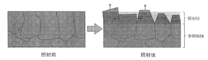
- Graphite material shrinks in the a-axis direction and expands in the c-axis direction by ion beam irradiation, but the expansion in the c-axis direction due to irradiation is absorbed by the existing voids. As it shrinks. At this time, as shown in the model diagram of FIG. 1, since the shrinkage is constrained by the non-irradiation region deeper than the region irradiated with the ion beam, it is considered that the shrinkage due to irradiation is absorbed by the expansion of the gap. For this reason, in a plane parallel to the sample surface, shrinkage is expressed by increasing the gap, and expansion is expressed by decreasing the gap.
- the ratio of the area of the opening of the gap on the surface of the sample in the ion beam irradiation area and the area of the portion excluding the gap is obtained and expressed by the following formula (1).
- the rate of change of the area ratio of the portion excluding the voids before and after ion beam irradiation is calculated.
- S (unirr) is the area ratio of the portion excluding the void on the sample surface before ion beam irradiation
- S (irr) is the area of the portion excluding the void on the sample surface after ion beam irradiation. It is a ratio.
- the method of measuring the ratio of the area of the opening of the gap on the ion beam irradiation surface and the area of the portion excluding the gap there is no particular limitation on the method of measuring the ratio of the area of the opening of the gap on the ion beam irradiation surface and the area of the portion excluding the gap, and any method can be adopted.
- an image of the surface of a sample is taken using a scanning electron microscope (SEM), a video microscope, etc., and this image processing is performed to make two gradations.
- SEM scanning electron microscope
- N W showing the portion excluding the void
- the portion of the sample surface where the void is removed by a simple method The area ratio can be determined.
- the SEM image enables measurement with higher accuracy.
- the portion that is determined to be the opening of the gap is displayed in black based on the image taken with the photographing magnification, the photographing contrast condition, etc. constant.
- a threshold value may be set as described.
- Area ratio of the portion excluding the gap number of white pixels N W / (number of white pixels N W + number of black pixels N B )
- the rate of change before and after irradiation of the sample is determined by the number of white pixels (N W (unirr)) indicating the portion excluding the gap in the sample image before the ion beam irradiation and the number of black pixels (N B ( unirr)), and the number of white pixels (N W (irr)) indicating the portion excluding the void in the sample image after ion beam irradiation and the number of black pixels (N B (irr)) indicating the opening of the void. And can be represented by the following formula (2).
- volume change rate conversion By the above-described method, the ratio of the area of the opening on the surface of the sample irradiated with the ion beam and the area of the portion excluding the space is obtained, and before and after the ion beam irradiation based on the above formula (1). After calculating the rate of change of the area ratio of the portion excluding the voids in the sample, by using the obtained rate of change of the area ratio, the volume change rate of the sample by ion beam irradiation (%) based on the following formula (3) Can be calculated.
- Volume change rate (%) [(S (irr) ⁇ S (unirr)) / S (unirr)] ⁇ 100 ⁇ 3/2 (3)
- 2D L is the rate of change of the area ratio, and can be represented by the above formula (1) ((S (irr) ⁇ S (unirr)) / S (unirr)).
- volume V (irr) of the sample after ion beam irradiation can be approximated by the following equation.
- V (irr) (L 0 + ⁇ L 0 ) 3 ⁇ L 0 3 (1 + 3D L )
- 3D L is the rate of change in volume
- S (irr) ⁇ S (unirr)) / S (unirr) represented by the above formula (1)
- volume change rate (%) [(S (irr) ⁇ S (unirr)) / S (unirr)] ⁇ 100 ⁇ 3/2 (3)
- the rate of change of the area ratio (N ( W (irr) ⁇ N W (unirr)) / N W (unirr)) the volume change rate due to ion beam irradiation can be calculated by the following equation (4).
- Volume change rate (%) [(N W (irr) ⁇ N W (unirr)) / N W (unirr)] ⁇ 100 ⁇ 3/2 (4)
- dpa (displacement per atom )
- dpa indicates the average number of times all the lattice atoms forming the material were ejected by radiation (neutrons or ions), and can be calculated by the above-described TRIM code.
- dpa is widely used for the purpose of comparing irradiation data obtained in different irradiation fields. Further, since the damage efficiency varies depending on the material even at the same irradiation amount in the same irradiation field, it is an index used for defining the degree of damage of the material.
- the method for measuring the volume change rate of the graphite material of the present invention is an effective method as an accelerated test method for predicting the dose dependency of the volume change rate of the graphite material by neutron irradiation.
- dimensional change prediction data due to neutron irradiation of graphite material is inconsistent with neutron irradiation test data by a short ion beam irradiation experiment and a relatively simple analysis method. It is possible to obtain dose-dependent data of volume variation with high accuracy.
- FIG. 1 The scanning electron microscope (SEM) image which shows the surface state before and behind irradiation of the graphite sample irradiated with the ion beam in Example 1.
- FIG. 1 The SEM image of the graphite sample irradiated with the ion beam in Example 1, and the image which made this 2 gradation.
- the graph which shows the known data which shows the dose dependence of the volume change rate of the graphite material by neutron irradiation, and the data of the volume change rate of the graphite material calculated
- Example 1 Ion beam irradiation A nuclear grade isotropic graphite material was processed to a length of 4mm x width 2mm x thickness 3mm to prepare a sample for ion beam irradiation. At this time, polishing was performed so that the average roughness on the surface excluding voids such as surface pores and relatively large cracks was almost constant for all samples.
- This sample was fixed to a SiC sample base by a holder having a slit of width ⁇ length of about 1 ⁇ 5 mm, and the sample surface was irradiated with 5.1 mV Si 2+ ions in a vacuum chamber.
- the ion beam irradiated surface of the graphite sample is in the range of about 4 ⁇ 1 mm.
- the sample temperature was controlled to 400 ° C. ⁇ 5 ° C. by a heater provided behind the sample base.
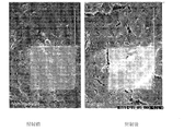
- FIG. 2 shows scanning electron microscope (SEM) images of the same part before and after ion beam irradiation of a sample irradiated with an ion beam so that the ion implantation amount is 1.8 ⁇ 10 21 ion / m 2 (8.8 dpa).
- the left figure is the SEM image before irradiation, and the right figure is the SEM image after irradiation. By comparing these SEM images, it can be confirmed that the size of the opening, particularly the crack, of the void on the sample surface was increased by ion beam irradiation.
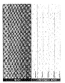
- Fig. 3 shows the SEM image and the SEM image after 2 gradation processing for each sample after irradiation.
- the upper figure is the SEM image
- the lower figure is the SEM image after the two-gradation processing corresponding to each SEM image.
- the opening of the gap of each sample is represented in black
- the portion excluding the gap is represented in white.
- the number of black pixels N B (irr) representing the opening of the gap in the SEM image of each sample after two gradations and the number N W (irr) of white pixels representing the part excluding the gap The area ratio of the opening portion (black pixel portion) of the gap was obtained, and the area ratio of the portion excluding the gap (for white pixels) was obtained by the same method.
- Area ratio of gap opening (%) [Number of black pixels N B (irr) / (number of white pixels N W (irr) + number of black pixels N B (irr))] ⁇ 100
- Volume change rate (%) [(N W (irr) ⁇ N W (unirr)) / Nw (unirr)] ⁇ 100 ⁇ 3/2
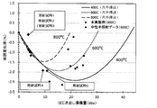
- FIG. 4 shows the known data described in Non-Patent Document 1 showing the dose dependence of the volume change rate of the graphite material by neutron irradiation, and the data of the volume change rate of the graphite material obtained by the ion beam irradiation method in Example 1.
- the radiation dose on the horizontal axis is indicated by dpa.
- the neutron irradiation dose is shown as a value converted to 1.4 ⁇ 10 25 n / m 2 as 1 dpa (see Carbon-Materials-Advanced-Technologies-Burchell, abebooks.com).
Landscapes
- Physics & Mathematics (AREA)
- Health & Medical Sciences (AREA)
- Life Sciences & Earth Sciences (AREA)
- Chemical & Material Sciences (AREA)
- Analytical Chemistry (AREA)
- Biochemistry (AREA)
- General Health & Medical Sciences (AREA)
- General Physics & Mathematics (AREA)
- Immunology (AREA)
- Pathology (AREA)
- Monitoring And Testing Of Nuclear Reactors (AREA)
- Analysing Materials By The Use Of Radiation (AREA)
Abstract
本発明は、測定対象の黒鉛材料に対してイオンビーム照射を行い、イオンビーム照射前とイオンビーム照射後の黒鉛材料について、材料表面の空隙を除いた部分の面積比率を求め、イオンビーム照射後の黒鉛材料における空隙を除いた部分の面積比率について、イオンビーム照射前の黒鉛材料における空隙を除いた部分の面積比率からの変化率を算出し、面積比率の変化率を体積変化率に換算することによって、黒鉛材料の体積変化率を求める方法を提供するものである。本発明方法によれば、短時間のイオンビーム照射実験と比較的簡単な解析方法によって、中性子照射の試験データと矛盾のない精度の高い体積変化量の線量依存性のデータを取得することができる。
Description
本発明は、高温ガス炉の炉内構造材料等として用いられる黒鉛材料について、中性子照射後の体積変化率を比較的短時間で見積もることが可能な、黒鉛材料の体積変化率の測定方法に関する。
高温ガス炉は、黒鉛減速ヘリウム冷却型中性子炉であり、試験研究炉として高温工学試験研究炉(HTTR)が製作され、運転されている。高温ガス炉では、減速材としては、中性子の吸収が少なく、放射線に強く、熱伝導性の良い黒鉛を用いている。黒鉛は、減速材と炉心構造材の機能を兼ねており、熱容量が大きいことから、事故時の急激な温度上昇を抑える役割も担っている。
この様な高温ガス炉の炉心及び炉内構造材料である黒鉛は、中性子の照射下で、損傷量増加に伴い収縮した後に、膨張に転じるという複雑な寸法変化を生じることが知られている。この現象は、中性子が黒鉛材料に衝突することによって炭素原子のはじき出しが起こり、これが連鎖して炭素原子のはじき出しの連鎖、いわゆるカスケード損傷が生じ、ミクロには基底面間での欠陥クラスタリングに伴うc軸膨張と、空孔導入に伴うa軸収縮が生じ、c軸膨張は既存ポアやマイクロクラックにより吸収されるため損傷初期、中期ではマクロには収縮が生じ、高線量になるとポアによる膨張吸収が飽和して、体積が増加することによるもの考えられる(下記非特許文献1参照)。
この収縮と膨張の変位点はターンアラウンド点と称されており、これが黒鉛材料の使用限界であるとされている。しかしながら、ガス冷却炉での使用が想定されている異方比1.1以下の原子炉級黒鉛に対する中性子の照射データは、非特許文献1に記載されている単一の温度(600℃)以外では極めて限られており、最も単純な照射温度および照射量の関数についても、予測モデルによる補完に頼っている。中性子照射実験による照射データ取得は黒鉛材料の評価にとって非常に重要であるが、ターンアラウンド点までの高線量照射データの取得には、数年の照射時間が必要であり、これが照射データ不足の主たる要因となっている。
高温ガス炉黒鉛構造物の設計用照射データの内外挿法による拡張 IG-110黒鉛構造物の設計用照射データの評価, JAEA-research 2009(8), 1-28,巻頭1~2, 2009-06、日本原子力研究開発機構
本発明は、上記した従来技術の現状に鑑みてなされたものであり、その主な目的は、中性子照射による黒鉛材料の寸法変化を、比較的短時間の試験で低コストで、しかも高精度で見積もることができる方法を提供することである。
本発明者は、上記した目的を達成すべく鋭意研究を重ねてきた。その結果、中性子照射と比較して黒鉛の損傷速度が非常に大きい、加速器を用いるイオンビーム照射法によって、比較的短時間の照射で照射線量と寸法変化との関係を求めることが可能となることを見出した。そして、イオンビーム照射後の黒鉛材料表面において観察できる、亀裂および既存ポアなどの空隙部分の開口部のサイズの変化量から、照射表面近傍の黒鉛材料の体積変化を見積もることができ、これによって、中性子照射のデータと矛盾のない精度の高い体積変化量の線量依存性のデータを短時間で取得できることを見出した。本発明は、この様な知見に基づいて更に検討を重ねた結果完成されたものである。
即ち、本発明は、下記の黒鉛材料の体積変化率の測定方法を提供するものである。
項1. (1)測定対象の黒鉛材料に対してイオンビーム照射を行い、
(2)イオンビーム照射前とイオンビーム照射後の黒鉛材料について、観察視野中の材料表面の空隙を除いた部分の面積比率を求め、
(3)イオンビーム照射後の黒鉛材料における空隙を除いた部分の面積比率について、イオンビーム照射前の黒鉛材料における空隙を除いた部分の面積比率からの変化率を算出し、
(4)上記項(3)で求めた面積比率の変化率を体積変化率に換算する、
ことを特徴とする黒鉛材料の体積変化率の測定方法。
項2. 上記項1の方法において、(4)工程における面積比率の変化率を体積変化率に換算する方法が、イオンビーム照射前の試料の空隙を除いた部分の面積比率(S(unirr))と、イオンビーム照射後の試料の空隙を除いた部分の面積比率(S(irr))に基づいて、下記式により体積変化率を算出する方法である、黒鉛材料の体積変化率の測定方法:
体積変化率(%)=[(S(irr)-S(unirr))/S(unirr)]×100×3/2
項3. 上記項1又は2の方法において、項1の(2)工程における空隙を除いた部分の面積比率を求める方法が、黒鉛材料表面の画像を撮影し、2階調化した後、2階調化された画像の黒ピクセル数NBと白ピクセル数NWを計測し、下記式により面積比率を算出する方法である、黒鉛材料の体積比率の測定方法
空隙を除いた部分の面積比率
=[白ピクセル数(NW)/(白ピクセル数(NW)+黒ピクセル数(NB))]
項4. 上記項3の方法において、項1の(3)及び(4)工程における面積比率の変化率を体積変化率に換算する方法が、イオンビーム照射前の試料とイオンビーム照射後の試料について画像を撮影し、2階調化した後、2階調化した画像の同一面積部分について、イオンビーム照射前の白ピクセルの数(Nw(unirr))と、イオンビーム照射後の白ピクセルの数(Nw(irr))を計測し、下記式により体積変化率を算出する方法である、黒鉛材料の体積変化率の測定方法:
体積変化率(%)=[(Nw(irr)-Nw(unirr))/Nw(unirr)]×100×3/2
項5. 上記項1~4のいずれかの方法において、イオンビームの照射量を原子あたりのはじき出し数:dpaに換算し、黒鉛材料の体積変化率をdpaを指標として評価することによる、中性子照射による黒鉛材料の体積変化率の予測方法。
項1. (1)測定対象の黒鉛材料に対してイオンビーム照射を行い、
(2)イオンビーム照射前とイオンビーム照射後の黒鉛材料について、観察視野中の材料表面の空隙を除いた部分の面積比率を求め、
(3)イオンビーム照射後の黒鉛材料における空隙を除いた部分の面積比率について、イオンビーム照射前の黒鉛材料における空隙を除いた部分の面積比率からの変化率を算出し、
(4)上記項(3)で求めた面積比率の変化率を体積変化率に換算する、
ことを特徴とする黒鉛材料の体積変化率の測定方法。
項2. 上記項1の方法において、(4)工程における面積比率の変化率を体積変化率に換算する方法が、イオンビーム照射前の試料の空隙を除いた部分の面積比率(S(unirr))と、イオンビーム照射後の試料の空隙を除いた部分の面積比率(S(irr))に基づいて、下記式により体積変化率を算出する方法である、黒鉛材料の体積変化率の測定方法:
体積変化率(%)=[(S(irr)-S(unirr))/S(unirr)]×100×3/2
項3. 上記項1又は2の方法において、項1の(2)工程における空隙を除いた部分の面積比率を求める方法が、黒鉛材料表面の画像を撮影し、2階調化した後、2階調化された画像の黒ピクセル数NBと白ピクセル数NWを計測し、下記式により面積比率を算出する方法である、黒鉛材料の体積比率の測定方法
空隙を除いた部分の面積比率
=[白ピクセル数(NW)/(白ピクセル数(NW)+黒ピクセル数(NB))]
項4. 上記項3の方法において、項1の(3)及び(4)工程における面積比率の変化率を体積変化率に換算する方法が、イオンビーム照射前の試料とイオンビーム照射後の試料について画像を撮影し、2階調化した後、2階調化した画像の同一面積部分について、イオンビーム照射前の白ピクセルの数(Nw(unirr))と、イオンビーム照射後の白ピクセルの数(Nw(irr))を計測し、下記式により体積変化率を算出する方法である、黒鉛材料の体積変化率の測定方法:
体積変化率(%)=[(Nw(irr)-Nw(unirr))/Nw(unirr)]×100×3/2
項5. 上記項1~4のいずれかの方法において、イオンビームの照射量を原子あたりのはじき出し数:dpaに換算し、黒鉛材料の体積変化率をdpaを指標として評価することによる、中性子照射による黒鉛材料の体積変化率の予測方法。
以下、本発明の測定方法について、詳細に説明する。
測定対象
本発明の測定対象は、黒鉛材料である。黒鉛材料の種類については特に限定はない。例えば、高温ガス炉の炉内構造物として用いられる微粒等方性黒鉛や人造黒鉛電極等の多孔質黒鉛材などを測定対象とすることができるが、異方性の黒鉛も測定対象とすることができる。特に、多孔質黒鉛材は、亀裂を含む空隙部を多く有するために、本発明の測定方法の測定対象として適したものである。
本発明の測定対象は、黒鉛材料である。黒鉛材料の種類については特に限定はない。例えば、高温ガス炉の炉内構造物として用いられる微粒等方性黒鉛や人造黒鉛電極等の多孔質黒鉛材などを測定対象とすることができるが、異方性の黒鉛も測定対象とすることができる。特に、多孔質黒鉛材は、亀裂を含む空隙部を多く有するために、本発明の測定方法の測定対象として適したものである。
測定対象の試料の形状については特に限定しないが、後述する方法によってイオンビームを照射した際に、照射面の損傷に基づく形状の変化、例えば、曲率の変化などによって照射面の面積変化が生じないように、イオンビームの飛程に対して500倍程度以上の厚さを有することが好ましく、特に、異方性の黒鉛については、曲率の変化が生じ易いので、イオンビームの飛程に対して1000倍程度以上の厚さを有することが好ましく、5000倍程度以上の厚さを有することがより好ましい。
測定試料の表面状態については、イオンビーム照射によって、できるだけ均一な深さにイオンが到達するように、表面平滑性が高いことが好ましく、これにより精度の高い測定が可能となる。例えば、イオンビーム照射面の表面の算術平均粗さRaが、照射されるイオンの飛程の1/10程度以下であることが好ましく、1/20程度以下であることがより好ましい。このため、必要に応じて、イオンビーム照射前に、微細な砥粒を用いて鏡面研磨をすればよい。例えば、測定対象の表面で測定される算術平均粗さRaが0.2μm以下のものを好適に用いることができる。算術平均粗さはJIS B 0601:2001に基づいて測定することができる。
測定方法
(1)イオンビーム照射
本発明方法では、まず、処理対象の黒鉛材料に対してイオンビーム照射を行う。イオンビーム照射では、黒鉛材料の損傷速度が、通常の原子炉照射と比較すると非常に大きく、例えば、3桁以上大きい損傷速度とすることもできる。また、入射粒子のエネルギーが高く、大きな一次はじき出し原子(PKA)エネルギーが得られるため、中性子照射の損傷モデルとしての基本的な要件であるカスケード損傷を起こすことが可能であると考えられる。更に、イオンビーム照射法は、照射条件(照射温度・損傷量(dpa)・損傷速度(dpa/s)など)を精密に設定、計測、制御することが可能であり、MeV級の重イオンでは試料の誘導放射化の心配が無く、安全である。特に照射温度400℃以上では損傷速度効果が小さいと見積もられているため、中性子照射とイオン照射間での損傷速度の違いによる現象の違いも限定的であると考えられる[Carbon Materials for Advanced Technologies, Edited by: Timothy D. Burchell, ISBN: 978-0-08-042683-9]。
(1)イオンビーム照射
本発明方法では、まず、処理対象の黒鉛材料に対してイオンビーム照射を行う。イオンビーム照射では、黒鉛材料の損傷速度が、通常の原子炉照射と比較すると非常に大きく、例えば、3桁以上大きい損傷速度とすることもできる。また、入射粒子のエネルギーが高く、大きな一次はじき出し原子(PKA)エネルギーが得られるため、中性子照射の損傷モデルとしての基本的な要件であるカスケード損傷を起こすことが可能であると考えられる。更に、イオンビーム照射法は、照射条件(照射温度・損傷量(dpa)・損傷速度(dpa/s)など)を精密に設定、計測、制御することが可能であり、MeV級の重イオンでは試料の誘導放射化の心配が無く、安全である。特に照射温度400℃以上では損傷速度効果が小さいと見積もられているため、中性子照射とイオン照射間での損傷速度の違いによる現象の違いも限定的であると考えられる[Carbon Materials for Advanced Technologies, Edited by: Timothy D. Burchell, ISBN: 978-0-08-042683-9]。
従って、イオンビーム照射法は、中性子照射による黒鉛材料の寸法変化を評価するための加速試験方法として有効な方法と考えられる。
イオンビーム照射は、常法に従って行えば良い。イオンビーム照射に用いるイオン種については、陽イオン化できるイオンであれば特に限定はない。また、イオンビームの照射条件についても特に限定はないが、黒鉛からの炭素原子のはじき出しのしきいエネルギーを超えたエネルギーを与え、カスケード損傷を生じさせた上で、更に、中性子照射による損傷状態の加速試験として十分な損傷速度を得るためには、通常、1MeV程度以上のエネルギーでイオンビーム照射を行うことが好ましい。
イオンビームのエネルギーの上限についても特に限定はないが、本発明方法では、イオンビーム照射によって生じる試料表面の収縮、膨張状態を観察し、これに基づいて寸法変化を評価するので、注入されたイオンの侵入深さである飛程は、試料の表面近傍で十分である。このため、使用するイオン種に応じて、例えば、飛程が最大で5μm程度となるエネルギーでイオンビーム照射を行えば十分であり、例えば、飛程が3μm程度であっても、精度のよい測定が可能である。
尚、注入したイオンの飛程については、TRIMコード(http://www.srim.org/参照)などのモンテカルロシミュレーションコードによって算出することができる。
また、中性子照射によって生じる黒鉛材料の寸法変化は試料温度に依存するので、イオンビーム照射の際には、試料の温度を目的とする温度近傍に維持する必要がある。通常は、目的とする試料温度±5℃程度の範囲となるように制御すればよい。例えば、試料ホルダに加熱用ヒータを設置して、イオンビーム照射の際の試料温度が一定温度範囲となるように制御すればよい。
イオンビーム照射時の雰囲気については、特に限定されないが、窒素、He、Ar等の不活性ガス雰囲気や真空雰囲気などの非酸化性雰囲気とすることが好ましい。
後述する通り、本発明方法では、試料表面の空隙の面積比率のイオンビーム照射前後での変化に基づいて体積変化を見積もるので、空隙の偏在の影響を排除して、精度の高い評価をするためには、測定対象面の広さは、測定面内に存在する主たる空隙である亀裂の長さに対して十分な広さを有することが好ましい。例えば、イオンビームを照射する範囲については、イオンビームの照射面に存在するイオンビーム照射前の亀裂の平均長さに対して、縦及び横の長さがいずれも100倍程度以上であることが好ましい。
(2)イオンビーム照射面の空隙の面積比率の測定
次いで、イオンビーム照射を行った黒鉛材料の照射面について、亀裂などの空隙の開口部の面積と空隙を除いた部分の面積の比率を求める。
次いで、イオンビーム照射を行った黒鉛材料の照射面について、亀裂などの空隙の開口部の面積と空隙を除いた部分の面積の比率を求める。
黒鉛材料は、イオンビーム照射によりa軸方向には収縮し、c軸方向には膨張するが、照射によるc軸方向の膨張は既存の空隙に吸収されるため、比較的低線量では、材料全体としては収縮する。この際、図1に示すモデル図のように、イオンビーム照射された領域より深い非照射域によってこの収縮が拘束されるために、照射による収縮が空隙の拡張により吸収されると考えられる。このため、試料表面に平行な面内で、収縮は空隙が大きくなることによって表現され、膨張は空隙が小さくなることによって表現される。
本発明方法によれば、イオンビーム照射前後の試料について、イオンビーム照射域における試料表面の空隙の開口部の面積と空隙を除いた部分の面積の比率を求め、下記式(1)で表されるイオンビーム照射前後における空隙を除いた部分の面積比率の変化率を算出する。式(1)において、S(unirr)はイオンビーム照射前の試料表面の空隙を除いた部分の面積比率であり、S(irr)はイオンビーム照射後の試料表面の空隙を除いた部分の面積比率である。
空隙を除いた部分の面積比率の変化率
= [(S(irr)-S(unirr))/S(unirr)] (1)
上記式(1)で表される面積比率の変化率を、後述する方法で体積変化率に換算することよって、イオンビーム照射前後の試料の体積変化率を求めることができる。
= [(S(irr)-S(unirr))/S(unirr)] (1)
上記式(1)で表される面積比率の変化率を、後述する方法で体積変化率に換算することよって、イオンビーム照射前後の試料の体積変化率を求めることができる。
イオンビーム照射面の空隙の開口部の面積と空隙を除いた部分の面積の比率を測定する方法については、特に限定はなく、任意の方法を採用できる。例えば、走査電子顕微鏡(SEM)、ビデオマイクロスコープ等を用いて試料表面の画像を撮影し、これ画像処理して2階調化した後、2階調化された画像において、空隙の開口部を示す黒のピクセル数NBと、空隙を除いた部分を示す白のピクセル数NWを計測し、下記式によりこの比率を算出することによって、簡単な方法で試料表面における空隙を除いた部分の面積の比率を求めることができる。特に、SEM像によればより精度の高い測定が可能となる。尚、SEM、ビデオマイクロスコープ等の画像を2階調化する方法については、撮影倍率、撮影コントラスト条件などを一定として撮影した画像に基づいて、空隙の開口部と判断される部分が黒で表示されるように、閾値を設定すればよい。
空隙を除いた部分の面積比率
=白ピクセル数NW/(白ピクセル数NW+黒ピクセル数NB)
=白ピクセル数NW/(白ピクセル数NW+黒ピクセル数NB)
イオンビーム照射前後において、2階調化した画像の観察視野面積を同一とすれば、白ピクセル数NWと黒ピクセル数NBの合計数は同一となるので、空隙を除いた部分の面積比率の照射前後での変化率は、イオンビーム照射前の試料の画像における空隙を除いた部分を示す白ピクセルの数(NW(unirr))と空隙の開口部を示す黒ピクセル数(NB(unirr))、及びイオンビーム照射後の試料の画像における空隙を除いた部分を示す白ピクセルの数(NW(irr))と空隙の開口部を示す黒ピクセル数(NB(irr))を用いて下記式(2)で表すことができる。
空隙を除いた部分の面積比率の変化率
=[NW(irr)/(NW(irr)+NB(irr))-NW(unirr)/(NW(unirr)+NB(unirr))]
/[NW(unirr)/(NW(unirr)+NB(unirr)]
=(NW(irr)-NW(unirr))/NW(unirr) (2)
=[NW(irr)/(NW(irr)+NB(irr))-NW(unirr)/(NW(unirr)+NB(unirr))]
/[NW(unirr)/(NW(unirr)+NB(unirr)]
=(NW(irr)-NW(unirr))/NW(unirr) (2)
(3)体積変化率換算
上記した方法によって、イオンビーム照射した試料表面の空隙の開口部の面積と空隙を除いた部分の面積の比率を求め、上記式(1)に基づいてイオンビーム照射前後における空隙を除いた部分の面積比率の変化率を算出した後、得られた面積比率の変化率を用いることによって、下記式(3)に基づいてイオンビーム照射による試料の体積変化率(%)を算出することができる。
上記した方法によって、イオンビーム照射した試料表面の空隙の開口部の面積と空隙を除いた部分の面積の比率を求め、上記式(1)に基づいてイオンビーム照射前後における空隙を除いた部分の面積比率の変化率を算出した後、得られた面積比率の変化率を用いることによって、下記式(3)に基づいてイオンビーム照射による試料の体積変化率(%)を算出することができる。
体積変化率(%)=[(S(irr)-S(unirr))/S(unirr)]×100×3/2 (3)
以下、上記式(3)で表される体積変化率の算出式について簡単に説明する。
イオンビーム照射後の試料の空隙を除いた部分の面積(A(irr))は、試料の照射前の空隙を除いた部分の面積A(unirr)をA(unirr)=L0
2で表し、A(irr)をA(irr)= (L0+ΔL )2で表せるように長さの単位L0及びΔLを導入して、照射後の長さの変化量ΔLがL0に比べて十分に小さいことを前提にすると下記式で近似できる。式中、DLは長さの変化率でありDL=ΔL /L0で表される。
A(irr) = (L0 + ΔL)2 = L0
2 + 2L0ΔL + ΔL2≒ L0
2(1 + 2DL)
ここで、2DLは、面積比率の変化率であり、上記式(1)((S(irr)-S(unirr))/S(unirr))で表すことができる。
ここで、2DLは、面積比率の変化率であり、上記式(1)((S(irr)-S(unirr))/S(unirr))で表すことができる。
同様に、イオンビーム照射後の試料の体積V(irr) は、下記式で近似することができる。
V(irr) = (L0 + ΔL0)3 ≒ L0
3(1 + 3DL)
ここで、3DLは、体積の変化率であり、上記式(1)で表される面積比率の変化率((S(irr)-S(unirr))/S(unirr))を用いると、下記式(3)で表すことができる。
ここで、3DLは、体積の変化率であり、上記式(1)で表される面積比率の変化率((S(irr)-S(unirr))/S(unirr))を用いると、下記式(3)で表すことができる。
体積変化率(%)=[(S(irr)-S(unirr))/S(unirr)]×100×3/2 (3)
尚、2階調化した画像の白ピクセル数と黒ピクセル数の計測結果に基づいてイオンビーム照射による体積変化率を求める場合には、上記式(2)で示される面積比率の変化率(NW(irr)-NW(unirr))/NW(unirr))を用いることによって、下記式(4)によってイオンビーム照射による体積変化率を算出することができる。
尚、2階調化した画像の白ピクセル数と黒ピクセル数の計測結果に基づいてイオンビーム照射による体積変化率を求める場合には、上記式(2)で示される面積比率の変化率(NW(irr)-NW(unirr))/NW(unirr))を用いることによって、下記式(4)によってイオンビーム照射による体積変化率を算出することができる。
体積変化率(%)=[(NW(irr)-NW(unirr))/NW(unirr)]×100×3/2(4)
(4)測定データの評価方法
上記した方法で求めたイオンビーム照射による体積変化率について、中性子照射による体積変化率との関連を評価する場合には、原子あたりのはじき出し数:dpa(displacement per atom)を放射線量の指標として評価すればよい。dpaは、材料を形成するすべての格子原子が放射線(中性子又はイオン)によって平均何回はじき出されたかを示すものであり、上記したTRIMコードよって算出することができる。dpaは、異なる照射場で得られた照射データを比較する目的で広く用いられている。また、同じ照射場での同じ照射量でも、材料によって損傷効率が異なるので、材料の損傷の度合いを定義するために使用される指標である。
上記した方法で求めたイオンビーム照射による体積変化率について、中性子照射による体積変化率との関連を評価する場合には、原子あたりのはじき出し数:dpa(displacement per atom)を放射線量の指標として評価すればよい。dpaは、材料を形成するすべての格子原子が放射線(中性子又はイオン)によって平均何回はじき出されたかを示すものであり、上記したTRIMコードよって算出することができる。dpaは、異なる照射場で得られた照射データを比較する目的で広く用いられている。また、同じ照射場での同じ照射量でも、材料によって損傷効率が異なるので、材料の損傷の度合いを定義するために使用される指標である。
本発明方法によれば、後述する実施例1の結果から明らかなように、イオンビーム照射線量の指標としてdpaを用いた場合に、イオンビーム照射の際のイオン飛程全域での平均損傷量(dpa)と体積変化率との関係が、中性子照射実験によって得られた損傷量(dpa)と体積変化率との関係の既知のデータと良く一致した結果となる。
従って、本発明の黒鉛材料の体積変化率の測定方法は、中性子照射による黒鉛材料の体積変化率の線量依存性を予測するための加速試験方法として有効な方法といえる。
以上の通り、本発明の測定方法によれば、黒鉛材料の中性子照射による寸法変化の予測データについて、短時間のイオンビーム照射実験と比較的簡単な解析方法によって、中性子照射の試験データと矛盾のない精度の高い体積変化量の線量依存性のデータを取得することができる。
以下、実施例を挙げて本発明を更に詳細に説明する。
実施例1
(1)イオンビーム照射
原子力級の等方性黒鉛材料を縦4mm×幅2mm×厚さ3mm程度に加工し、イオンビーム照射用試料を作製した。この際、表面のポアや比較的サイズの大きな亀裂などの空隙を除いた表面における、平均の粗さが全ての試料でほぼ一定になるように研磨を行った。
(1)イオンビーム照射
原子力級の等方性黒鉛材料を縦4mm×幅2mm×厚さ3mm程度に加工し、イオンビーム照射用試料を作製した。この際、表面のポアや比較的サイズの大きな亀裂などの空隙を除いた表面における、平均の粗さが全ての試料でほぼ一定になるように研磨を行った。
この試料を幅×長さが約1×5mmのスリットを有するホルダによってSiC製の試料ベースに固定して、真空チャンバー内で、Si2+イオンを5.1MeVで試料表面に照射した。黒鉛試料のイオンビーム照射面は約4×1mmの範囲である。イオンビーム照射時には、試料ベースの後方に設けたヒータにより、試料温度を400℃±5℃に制御した。
この方法により、イオン注入量が6.7×10²⁰ion/m2(3.3dpa)となるようにイオンビーム照射した試料3個と、イオン注入量が1.8×1021ion/m2(8.8dpa)となるようにイオンビーム照射した試料1個と、イオン注入量が2.0×1021ion/m2(9.9dpa)となるようにイオンビーム照射した試料を1個作製した。
図2に、イオン注入量1.8×10²¹ion/m2(8.8dpa)となるようにイオンビーム照射した試料について、イオンビーム照射前と照射後の同一部分の走査電子顕微鏡(SEM)像を示す。左図が照射前のSEM像であり、右図が照射後のSEM像である。これらのSEM像の比較により、イオンビーム照射によって、試料表面の空隙の開口部、特に亀裂のサイズが拡大したことが確認できる。
(2)空隙開口部の面積比率の算出
上記した方法でイオンビーム照射を行った各試料について、照射面の走査電子顕微鏡(SEM)像を撮影し、SEM像より空隙の開口部と判断される部分が黒で表されるように2階調化処理を行った。
上記した方法でイオンビーム照射を行った各試料について、照射面の走査電子顕微鏡(SEM)像を撮影し、SEM像より空隙の開口部と判断される部分が黒で表されるように2階調化処理を行った。
照射後の各試料について、SEM像と2階調化処理後のSEM像を図3に示す。上図がSEM像であり、下図がそれぞれのSEM像に対応する2階調化処理後のSEM像である。2階調化後のSEM像によれば、各試料の空隙の開口部が黒で表され、空隙を除いた部分が白で表されている。
各試料の2階調化後のSEM像における空隙の開口部を表す黒のピクセル数NB(irr)と、空隙を除いた部分を表す白のピクセル数NW(irr)より、下記式より空隙の開口部(黒ピクセル部)の面積比率を求め、同様の方法で空隙を除いた部分(白ピクセル分)の面積比率を求めた。
空隙開口部の面積比率(%)
=[黒ピクセル数NB(irr)/(白ピクセル数NW(irr)+黒ピクセル数NB(irr))]×100
=[黒ピクセル数NB(irr)/(白ピクセル数NW(irr)+黒ピクセル数NB(irr))]×100
(3)体積変化率の算出
次いで、上記した方法で求めたイオンビーム照射後の試料の2階調化処理後のSEM像における空隙を除いた部分を示す白ピクセルの数NW(irr))と、イオンビーム照射前の試料について、照射後の試料と同一の方法で2階調化したSEM像から求めた空隙を除いた部分を示す白ピクセルの数(NW(unirr))の計測値を用いて、下記式によりイオンビーム照射による試料の体積変化率を求めた。
次いで、上記した方法で求めたイオンビーム照射後の試料の2階調化処理後のSEM像における空隙を除いた部分を示す白ピクセルの数NW(irr))と、イオンビーム照射前の試料について、照射後の試料と同一の方法で2階調化したSEM像から求めた空隙を除いた部分を示す白ピクセルの数(NW(unirr))の計測値を用いて、下記式によりイオンビーム照射による試料の体積変化率を求めた。
体積変化率(%)=[(NW(irr)-NW(unirr))/Nw(unirr)]×100×3/2
(4)測定結果の評価
以上の結果を下記表1に示す。尚、イオンビームの照射量については、はじき出し損傷量をdpa単位で表した数値も示す。dpaの算出は、TRIMコードを用いて行い、黒鉛のはじき出しのしきいエネルギーは、従来広く用いられている35eVを使用し、黒鉛の密度は、実測値である1.75g/cm3を使用した。
以上の結果を下記表1に示す。尚、イオンビームの照射量については、はじき出し損傷量をdpa単位で表した数値も示す。dpaの算出は、TRIMコードを用いて行い、黒鉛のはじき出しのしきいエネルギーは、従来広く用いられている35eVを使用し、黒鉛の密度は、実測値である1.75g/cm3を使用した。

図4は、中性子照射による黒鉛材料の体積変化率の線量依存性を示す非特許文献1に記載の既知のデータと、実施例1でイオンビーム照射法によって求めた黒鉛材料の体積変化率のデータを示すグラフであり、横軸の放射線量をdpaによって示したものである。図4のグラフでは、中性子照射量は、1.4×1025n/m2を1dpaとして換算した値で示す(Carbon-Materials-Advanced-Technologies-Burchell, abebooks.com参照)。
図4から明らかなように、中性子照射による体積変化率のグラフにおける400℃でのデータを、イオンビーム照射法によって実施例1で求めた体積変化率の測定値と比較した場合に、放射線照射量をdpaで表した場合に、精度の良い一致が認められた。
この結果から、イオンビーム照射法によって照射イオン量を適切に制御して損傷試験を行うことによって、中性子照射による損傷試験と比較して非常に短時間で、中性子照射による黒鉛材料の損傷による寸法変化の予測データを取得することが可能であることが判る。
Claims (5)
- (1)測定対象の黒鉛材料に対してイオンビーム照射を行い、
(2)イオンビーム照射前とイオンビーム照射後の黒鉛材料について、観察視野中の材料表面の空隙を除いた部分の面積比率を求め、
(3)イオンビーム照射後の黒鉛材料における空隙を除いた部分の面積比率について、イオンビーム照射前の黒鉛材料における空隙を除いた部分の面積比率からの変化率を算出し、
(4)上記項(3)で求めた面積比率の変化率を体積変化率に換算する、
ことを特徴とする黒鉛材料の体積変化率の測定方法。 - 請求項1の方法において、(4)工程における面積比率の変化率を体積変化率に換算する方法が、イオンビーム照射前の試料の空隙を除いた部分の面積比率(S(unirr))と、イオンビーム照射後の試料の空隙を除いた部分の面積比率(S(irr))に基づいて、下記式により体積変化率を算出する方法である、黒鉛材料の体積変化率の測定方法:
体積変化率(%)=[(S(irr)-S(unirr))/S(unirr)]×100×3/2 - 請求項1又は2の方法において、請求項1の(2)工程における空隙を除いた部分の面積比率を求める方法が、黒鉛材料表面の画像を撮影し、2階調化した後、2階調化された画像の黒ピクセル数NBと白ピクセル数Nwを計測し、下記式により面積比率を算出する方法である、黒鉛材料の体積変化率の測定方法:
空隙を除いた部分の面積比率(%)
=[白ピクセル数NW/(白ピクセル数NW+黒ピクセル数NB)]×100 - 請求項3の方法において、請求項1の(3)及び(4)工程における面積比率の変化率を体積変化率に換算する方法が、イオンビーム照射前の試料とイオンビーム照射後の試料について画像を撮影し、2階調化した後、2階調化した画像の同一面積部分について、イオンビーム照射前の白ピクセルの数(Nw(unirr))と、イオンビーム照射後の白ピクセルの数(Nw(irr))を計測し、下記式により体積変化率を算出する方法である、黒鉛材料の体積変化率の測定方法:
体積変化率(%)=[(NW(irr)-NW(unirr))/NW(unirr)]×100×3/2 - 請求項1~4のいずれかの方法において、イオンビームの照射量を原子あたりのはじき出し数:dpaに換算し、黒鉛材料の体積変化率をdpaを指標として評価することによる、中性子照射による黒鉛材料の体積変化率の予測方法。
Priority Applications (1)
| Application Number | Priority Date | Filing Date | Title |
|---|---|---|---|
| JP2014533100A JP6316190B2 (ja) | 2012-08-31 | 2013-08-30 | 黒鉛材料の体積変化率測定方法および黒鉛材料の体積変化率予測方法 |
Applications Claiming Priority (2)
| Application Number | Priority Date | Filing Date | Title |
|---|---|---|---|
| JP2012191583 | 2012-08-31 | ||
| JP2012-191583 | 2012-08-31 |
Publications (1)
| Publication Number | Publication Date |
|---|---|
| WO2014034829A1 true WO2014034829A1 (ja) | 2014-03-06 |
Family
ID=50183634
Family Applications (1)
| Application Number | Title | Priority Date | Filing Date |
|---|---|---|---|
| PCT/JP2013/073259 Ceased WO2014034829A1 (ja) | 2012-08-31 | 2013-08-30 | 黒鉛材料の体積変化率測定方法および黒鉛材料の体積変化率予測方法 |
Country Status (2)
| Country | Link |
|---|---|
| JP (1) | JP6316190B2 (ja) |
| WO (1) | WO2014034829A1 (ja) |
Cited By (1)
| Publication number | Priority date | Publication date | Assignee | Title |
|---|---|---|---|---|
| RU2625457C2 (ru) * | 2015-04-02 | 2017-07-14 | Акционерное общество "Ордена Ленина Научно-исследовательский и конструкторский институт энерготехники им. Н.А. Доллежаля" (АО "НИКИЭТ") | Способ контроля состояния графитовой кладки реактора рбмк |
Citations (2)
| Publication number | Priority date | Publication date | Assignee | Title |
|---|---|---|---|---|
| JPH04305195A (ja) * | 1991-04-02 | 1992-10-28 | Mitsubishi Heavy Ind Ltd | 熱交換器の内部検査装置 |
| JP2001194481A (ja) * | 2000-01-17 | 2001-07-19 | Japan Atom Energy Res Inst | 原子炉用黒鉛構造物の長寿命化の方法 |
-
2013
- 2013-08-30 WO PCT/JP2013/073259 patent/WO2014034829A1/ja not_active Ceased
- 2013-08-30 JP JP2014533100A patent/JP6316190B2/ja active Active
Patent Citations (2)
| Publication number | Priority date | Publication date | Assignee | Title |
|---|---|---|---|---|
| JPH04305195A (ja) * | 1991-04-02 | 1992-10-28 | Mitsubishi Heavy Ind Ltd | 熱交換器の内部検査装置 |
| JP2001194481A (ja) * | 2000-01-17 | 2001-07-19 | Japan Atom Energy Res Inst | 原子炉用黒鉛構造物の長寿命化の方法 |
Non-Patent Citations (1)
| Title |
|---|
| "Expansion of irradiation data by interpolation and extrapolation for design of graphite components in High Temperature Gas-cooled Reactor: evaluation on IG-110 graphite irradiation data for component design", JAEA- RESEARCH, June 2009 (2009-06-01), pages I - IV, 1 - 28 * |
Cited By (1)
| Publication number | Priority date | Publication date | Assignee | Title |
|---|---|---|---|---|
| RU2625457C2 (ru) * | 2015-04-02 | 2017-07-14 | Акционерное общество "Ордена Ленина Научно-исследовательский и конструкторский институт энерготехники им. Н.А. Доллежаля" (АО "НИКИЭТ") | Способ контроля состояния графитовой кладки реактора рбмк |
Also Published As
| Publication number | Publication date |
|---|---|
| JPWO2014034829A1 (ja) | 2016-08-08 |
| JP6316190B2 (ja) | 2018-04-25 |
Similar Documents
| Publication | Publication Date | Title |
|---|---|---|
| Ni et al. | Focussed ion beam sectioning for the 3D characterisation of cracking in oxide scales formed on commercial ZIRLO™ alloys during corrosion in high temperature pressurised water | |
| Moorehead et al. | Comprehensive investigation of the role of Nb on the oxidation kinetics of Zr-Nb alloys | |
| Swenson et al. | The comparison of microstructure and nanocluster evolution in proton and neutron irradiated Fe–9% Cr ODS steel to 3 dpa at 500 C | |
| Platt et al. | A study into stress relaxation in oxides formed on zirconium alloys | |
| Lhuillier et al. | Trapping and release of helium in tungsten | |
| Klimenkov et al. | TEM study of beryllium pebbles after neutron irradiation up to 3000 appm helium production | |
| Sonoda et al. | Clarification of high density electronic excitation effects on the microstructural evolution in UO2 | |
| Campbell et al. | Proton irradiation-induced creep of ultra-fine grain graphite | |
| Jiang et al. | A novel method for quantifying irradiation damage in nuclear graphite using Raman spectroscopy | |
| Lach et al. | Fission recoil-induced microstructural evolution of the fuel-cladding interface [FCI] in high burnup BWR fuel | |
| Maya et al. | Evaluation of tungsten as divertor plasma-facing material: results from ion irradiation experiments and computer simulations | |
| Ward et al. | Influence of proton-irradiation temperature on the damage accumulation in Ti3SiC2 and Ti3AlC2 | |
| Nishijima et al. | Deuterium supersaturated surface layer in tungsten: ion energy dependence | |
| JP6316190B2 (ja) | 黒鉛材料の体積変化率測定方法および黒鉛材料の体積変化率予測方法 | |
| Komarov et al. | Radiation resistance of structural materials of nuclear reactors on irradiation with high-energy hydrogen and helium ions | |
| Posselt et al. | Energetics, structure and composition of nanoclusters in oxide dispersion strengthened Fe–Cr alloys | |
| Amrastanov et al. | Estimation of the heating of a semiconductor target surface by a low-energy electron beam | |
| Jóźwik et al. | Analysis of crystal lattice deformation by ion channeling | |
| Onofri et al. | Experimental characterizations by EBSD and TEM of sub-grain boundaries and dislocations in low irradiated UO2 fuels | |
| Moore et al. | In-pile irradiation induced defects and the effect on thermal diffusivity of MgO | |
| Gutierrez et al. | High temperature annealing of Xe implanted ZrC0. 95O0. 05 investigated by RBS, TEM and PAS-DBS | |
| CN112525933A (zh) | 一种空心叶片残芯中子检测灵敏度的参考线确定方法 | |
| Khripunov et al. | Radiation-damaged tungsten: Production and study in a steady-state plasma flux | |
| Zhao et al. | Helium plasma-induced surface modifications of unirradiated and pre-ion irradiated tungsten at LHD divertor leg position | |
| Liu | High resolution structural analysis of irradiated zirconium alloys |
Legal Events
| Date | Code | Title | Description |
|---|---|---|---|
| 121 | Ep: the epo has been informed by wipo that ep was designated in this application |
Ref document number: 13834097 Country of ref document: EP Kind code of ref document: A1 |
|
| ENP | Entry into the national phase |
Ref document number: 2014533100 Country of ref document: JP Kind code of ref document: A |
|
| NENP | Non-entry into the national phase |
Ref country code: DE |
|
| 122 | Ep: pct application non-entry in european phase |
Ref document number: 13834097 Country of ref document: EP Kind code of ref document: A1 |