WO2014032113A1 - A solvent based carbon capture process and plant and a method of sizing and/or configuring same - Google Patents
A solvent based carbon capture process and plant and a method of sizing and/or configuring same Download PDFInfo
- Publication number
- WO2014032113A1 WO2014032113A1 PCT/AU2013/000978 AU2013000978W WO2014032113A1 WO 2014032113 A1 WO2014032113 A1 WO 2014032113A1 AU 2013000978 W AU2013000978 W AU 2013000978W WO 2014032113 A1 WO2014032113 A1 WO 2014032113A1
- Authority
- WO
- WIPO (PCT)
- Prior art keywords
- based carbon
- plant
- solvent based
- gas
- column
- Prior art date
- Legal status (The legal status is an assumption and is not a legal conclusion. Google has not performed a legal analysis and makes no representation as to the accuracy of the status listed.)
- Ceased
Links
Classifications
-
- B—PERFORMING OPERATIONS; TRANSPORTING
- B01—PHYSICAL OR CHEMICAL PROCESSES OR APPARATUS IN GENERAL
- B01D—SEPARATION
- B01D53/00—Separation of gases or vapours; Recovering vapours of volatile solvents from gases; Chemical or biological purification of waste gases, e.g. engine exhaust gases, smoke, fumes, flue gases, aerosols
- B01D53/14—Separation of gases or vapours; Recovering vapours of volatile solvents from gases; Chemical or biological purification of waste gases, e.g. engine exhaust gases, smoke, fumes, flue gases, aerosols by absorption
- B01D53/1456—Removing acid components
- B01D53/1475—Removing carbon dioxide
-
- Y—GENERAL TAGGING OF NEW TECHNOLOGICAL DEVELOPMENTS; GENERAL TAGGING OF CROSS-SECTIONAL TECHNOLOGIES SPANNING OVER SEVERAL SECTIONS OF THE IPC; TECHNICAL SUBJECTS COVERED BY FORMER USPC CROSS-REFERENCE ART COLLECTIONS [XRACs] AND DIGESTS
- Y02—TECHNOLOGIES OR APPLICATIONS FOR MITIGATION OR ADAPTATION AGAINST CLIMATE CHANGE
- Y02C—CAPTURE, STORAGE, SEQUESTRATION OR DISPOSAL OF GREENHOUSE GASES [GHG]
- Y02C20/00—Capture or disposal of greenhouse gases
- Y02C20/40—Capture or disposal of greenhouse gases of CO2
Definitions
- the present invention relates to a solvent based carbon capture process and plant and a method of sizing and/or configuring same.
- Solvent based post-combustion carbon capture has been evaluated and described as the most mature technology for commercial scale industrial carbon capture from power plant flue gas. The technology is currently used in different small-scale industrial applications. Indeed, PCC began in the 1970s not out of concern for climate change but as a potential economic source of C0 2 for enhanced oil recovery (EOR) operations.
- Figure 1 shows a schematic of a solvent-based PCC process. The flue gas, with a temperature range of 40-60 °C passes through the absorber column (packed or tray) where the lean solvent enters from the top of the absorber in a countercurrent process.
- the solvent removes CO2 from the flue gas through physico-chemical interaction; the rich solvent then exits from the bottom of the absorber while the cleaned flue gas leaves the absorber overhead towards the stack.
- the rich solvent is stripped of C0 2 by thermal treatment at 100-120 °C. The lean solvent is recycled to the absorber while the C0 2 is sent from overhead to the compression unit.
- a method of determining the size and/or configuration of a solvent based carbon capture process and/or plant for a source of gas including carbon dioxide wherein the configuration includes one or more absorber columns and one or more desorber columns including the following steps: a) providing information including: percentage of carbon dioxide capture, composition of the source of gas, flow rate of the source of gas, and solvent type; and, b) deteniuning the size and/or configuration of the solvent based carbon capture process, wherein, step b includes determining the value of one or more design parameters and one of more operational parameters of the solvent based carbon capture process and/or plant.
- the method includes implementing a solvent based carbon capture plant according to the determined size and configuration of the solvent based carbon capture process and or plant.
- the one or more design parameters of the solvent based carbon capture process and/or plant are selected from the following: the number of absorber columns, the number of desorber columns, the diameter of the absorber column(s), the diameter of the desorber column(s), the height of the absorber column(s), the height of the desorber column(s), the type of packing of the absorber column(s), and the type of packing of the desorber cotumn(s).
- the one or more operational parameters of the solvent based carbon capture process and/or plant are selected from the following: the ratio of gas to liquid flow rates entering the absorber and/or the desorber, the ratio of the source of gas including carbon dioxide to solvent, the carbon dioxide capture rate, the temperature of the gas including carbon dioxide, the temperature of the inlet gas to the desorber, the solvent temperature, the lean and rich loadings of the solvent, the operating pressure of the absorber column(s), the operating pressure of the desorber column(s), the duty of the boiler associated with the desorber column(s).
- step b includes the following steps: i. providing a mathematical model of the solvent based carbon capture process and/or plant dependent upon the one or more design parameters and the one or more operational parameters; ii. determining one or more objective functions associated with the mathematical model; and, iii. determining the value of the one or more design parameters and the one or more operational parameters within the mathematical model which correspond to the one or more objective functions to thereby determine the size and/or configuration of the solvent based carbon capture process and/or plant.
- the mathematical model of the solvent based carbon capture process and/or plant includes the following; ⁇ calculation of the number of absorber columns;
- the one or more objective functions associated with the mathematical model includes the minimisation of the capital installation cost and/or the operating cost of the solvent based carbon capture process and/or plant.
- the objective function associated with the mathematical model includes one or more of the following: economic objective functions, techno-economic objective functions, and/or technical objective functions.
- objective function is selected from: minimising the capital cost of the solvent based carbon capture process, minimising the operating cost of the solvent based carbon capture process, the net present value and/or combinations thereof.
- the source of the gas is derived from a fossil fuel combustion process.
- a solvent based carbon capture process and/or plant that has been sized and/or configured by the method as herein described.
- a method of detennining the size and/or configuration of a solvent based carbon capture process and/or plant for a source of gas including carbon dioxide wherein the configuration includes one or more absorber columns and one or more desorber columns wherein the method includes: a. a processing system obtaining information including: percentage of carbon dioxide capture, composition of the source of gas, flow rate of the source of gas, and solvent type; and, b. the processing system determining the size and/or configuration of the solvent based carbon capture process, wherein, step b includes determining the value of one or more design parameters and one or more operational parameters of the solvent based carbon capture process and/or plant.
- the method includes the processing system: i. providing a mathematical model of the solvent based carbon capture process and or plant dependent upon the one or more design parameters and the one or more operational parameters; ii. determining one or more objective functions associated with the mathematical model; and iii. determining the value of the one or more design parameters and the one or more operational parameters within the mathematical model which corresponds to the one or more objective functions to thereby determine the size and/or configuration of the solvent based carbon capture process and/or plant.
- the method includes the processing system iteratively manipulating the one or more design parameters and the one or more operational parameters within the mathematical model to determine the value of the one or more design parameters and the one or more operational parameters which corresponds to the one or more objective functions.
- a processing system for determining the size and/or configuration of a solvent based carbon capture process and/or plant for a source of gas including carbon dioxide wherein the configuration includes one or more absorber columns and one or more desorber columns, wherein the processing system is configured to: a. obtain information including: percentage of carbon dioxide capture, composition of the source of gas, flow rate of the source of gas, and solvent type; and, b. determine the size and/or configuration of the solvent based carbon capture process; wherein the determination by the processing system includes detennining the value of one or more design parameters and one or more operational parameters of the solvent based carbon capture process and/or plant.
- the method includes the processing system: i. providing a mathematical model of the solvent based carbon capture process and/or plant dependent upon the one or more design parameters and the one or more operational parameters; ii. determining one or more objective functions associated with the mathematical; and iii. determining the value of the one or more design parameters and the one or more operational parameters within the mathematical model which correspond to the one or more objective functions to thereby determine the size and/or configuration of the solvent based carbon capture process and/or plant.
- the processing system is configured t iteratively manipulate the one or more design parameters and the one or more operational parameters within the mathematical model to determine the value of the one or more design parameters and the one or more operational parameters which corresponds to the one or more objective functions.
- a computer readable medium for configuring a processing system to determine the size and/or configuration of a solvent based carbon capture process and/or plant for a source of gas including carbon dioxide wherein the configuration includes one or more absorber columns and one or more desorber columns, wherein the computer readable medium includes executable instructions for configuring the processing system to: a. obtain information including; percentage of carbon dioxide capture, composition of the source of gas, flow rate of the source of gas, and solvent type; and, b. determine the size and/or configuration of the solvent based carbon capture process; wherein the determination by the processing system includes determining the value of one or more design parameters and one or more operational parameters of the solvent based carbon capture process and/or plant.
- the executable instructions configure the processing system to: - 7 - i. provide a mathematical model of the solvent based carbon capture process dependent upon the one or more design parameters and the one or more operational parameters; ii. determine one or more objective functions associated with the mathematical model; and iii. determining the value of the one or more design parameters and the one or more operational parameters within the mathematical model which correspond with the one or more objective functions to thereby determine the size and/or configuration of the solvent based carbon capture process and/or plant.
- the executable instructions configure the processing system to iteratively manipulate the one or more design parameters and the one or more operational parameters within the mathematical model until the one or more objective functions are optimised.
- an absorber associated with a solvent based carbon capture process and/or plant wherein the absorber has been sized by providing information including: percentage of carbon dioxide capture, composition of the source of gas, flow rate of the source of gas, and solvent type; and determining the value of one or more design parameters and one or more operational parameters of the solvent based carbon capture process and/or plant.
- determining the value of one or more design parameters and one or more operational parameters of the solvent based carbon capture process and/or plant includes providing a mathematical model of the solvent based carbon capture process and/or plant dependent upon the one or more design parameters and the one or more operational parameters, determining one or more objective functions associated with the mathematical model; and determining the value of the one or more design parameters and the one or more operational parameters within the mathematical model which correspond to the one or more objective functions to thereby determine the size of the absorber.
- the absorber is sized by providing one or more of the following parameters: the height of the absorber, the diameter of the absorber, the packing height of the absorber and/or the packing type.
- a desorber associated with a solvent based carbon capture process and/or plant wherein the desorber has been sized by providing information including: percentage of carbon dioxide capture, composition of the source of gas, flow rate of the source of gas, and solvent type; and determining the value of one or more design parameters and one or more operational parameters of the solvent based carbon capture process and/or plant.
- determining the value of one or more design parameters and one or more operational parameters of the solvent based carbon capture process and/or plant includes providing a mathematical model of the solvent based carbon capture process and/or plant dependent upon the one or more design parameters and the one or more operational parameters, determining one or more objective functions associated with the mathematical model; and determining the value of the one or more design parameters and the one or more operational parameters within the mathematical model which correspond to the one or more objective functions to thereby determine the size of the absorber.
- the desorber is sized by providing one or more of the following parameters: the height of the desorber, the diameter of the desorber, the packing height of the desorber and/or the packing type.
- a solvent based carbon capture plant including an absorber as herein described and/or a desorber as herein described.
- Figure 1 is a schematic diagram of a solvent based post combustion carbon capture process
- Figure 2 illustrates a functional block diagram of an example processing system that can be utilised to embody or give effect to a particular embodiment
- Figure 3 illustrates an example network infrastructure that can be utilised to embody or give effect to a particular embodiment
- Figure 4 is a schematic diagram of a solvent based post combustion carbon capture process designed for a 300 MWe coal-fired power plant
- Figure 5 is a flow chart outlining a method of one embodiment of the present invention.
- Figure 6 is a flowchart representing a simplified column design algorithm
- Figure 7 is a flowchart representing a design algorithm of an absorber column
- Figure 8 is a flowchart representing a design algorithm of a desorber column
- Figure 9 is a schematic of a packed column model structure
- Figure 10 is a schematic of a desorber
- Figure 11 is a schematic of solvent-based PCC process configuration for a 300 MWe coal fired power plant for example I;
- Figure 12 is a flowchart representing an overall PCC process synthesis and design methodology for example 2;
- Figure 13 is a flowchart representing a simplified column design algorithm for example 2;
- Figure 14 is a flowchart representing a design algorithm of an absorber column for example 2.
- Figure 15 is a flowchart representing a design algorithm of a desorber column for example 2.
- the present invention provides a method of determining the size and/or configuration of a solvent based carbon capture process and/or plant for a source of gas which includes carbon dioxide.
- the source of gas may be from any source that provides a gas including carbon dioxide such as for example flue gas exiting from a combustion reaction, a natural gas source, and synthesis gas from a gasification reaction.
- a typical example of a solvent based carbon capture process is depicted in the schematic of Figure 1.
- the source of gas including carbon dioxide (denoted as flue gas 10) is reduced in temperature by via indirect heat transfer 12 before entering the absorber column 15 (which may be packed or tray).
- a lean solvent 20 enters the top of the absorber 15 providing a countercurent arrangement with the flue gas 21 within the absorber 15.
- the solvent removes carbon dioxide from the flue gas through physico-chemical interaction and the rich solvent then exits from the bottom 22 of the absorber 15 while the cleaned flue gas leaves the absorber 15 overhead 25.
- the rich solvent then passes to the stripper column 35 where it is stripped of carbon dioxide by thermal treatment.
- the lean solvent 20 is recycled to the absorber 15 while the carbon dioxide is sent from the overhead 38 of the stripper 35 column to a compression unit.
- the method of determining the size and/or configuration of a solvent based carbon capture process includes a two step method wherein the first step (step a) includes providing information or values on parameters of the solvent based carbon capture process which are constant and are not able to be varied.
- the next step (step b) involves determining the size and/or configuration of the solvent based carbon capture process using a mathematical model of the solvent based carbon capture process which is dependent upon a combination of various design parameters and various operational parameters.
- Step b further includes determining one or more objective functions which are associated with the mathematical model of the solvent based carbon capture process. Once the one or more objective functions are determined, step b then further includes determining the one or more of the design parameters and operational parameters until a result is achieved which corresponds with or aligns with the objective function. Once correspondence has been achieved, the values provided for the various design parameters and the various operational parameters provide the basis for the size and configuration of the solvent based carbon capture process or plant that corresponds with the one or more objective functions.
- the first step (step a) of the method involves providing information or values on parameters of the solvent based carbon capture process which are constant and are not to be, or not able to be varied: Such values include:
- Flue gas fiowrate • Flue gas composition (for example C0 2 , H 2 0, N 2 , etc.)
- Solvent type and its composition for example monoethanolamine or MEA.
- step b involves determining the size and/or configuration of the solvent based carbon capture process using a mathematical model of the solvent based carbon capture process which is dependent upon a combination of various design parameters and various operational parameters.
- a mathematical model of the solvent based carbon capture process which is dependent upon a combination of various design parameters and various operational parameters.
- Some parameters of the mathematical model which may be directly linked with the optimization stage (X ⁇ -Xg). There are however, some other parameters which may be determined in the synthesis/design stage (X lQ - X 2 ⁇ ) and are indirectly linked with the optimization stage.
- the mathematical model of the solvent based carbon capture process begins with the absorber design (item C in Figure 5). With the given values of the parameters outlined above, the absorber model is calculated using the mathematical model and steps shown in the following absorber flow charts. The details on the parameters providing the design and configuration of the absorber model (item D in Figure 5) are given below.
- the main model outputs are the following parameters: • Number of columns (3 ⁇ 4)
- the diameter and/or height of the absorber which is calculated exceed the maximum limits given by the designer at step a above, the number of columns is increased, the inlet gas flowrate for each column is updated and then the absorber model calculatio is repeated. Once the satisfactory results are achieved, the synthesis/design task is continued with the desorber column(s) synthesis/design.
- a methodology similar to the absorber is followed for the desorber (item E in Figure 5) using the model shown in the desorber flow chart appearing and discussed below.
- the main outputs of the desorber model are the following parameters:
- the first stage of determining the size and or configuration of the solvent based carbon capture process and/or plant is completed.
- the second stage of the methodology i.e. optimization is pursued.
- One or more objective functions (e.g.: max NPV, min CAPEX, min OPEX, etc.) is determined.
- An example of objective function formulation as net-present-value of cash flow (CF- PV) is given below.
- the mathematical model then proceeds to determine the value of the variable parameters to select a new set of values (for parameters X ⁇ - X9) and repeat the methodology until the value of the variable parameters corresponds with the one or more objective functions. Therefore the final optimized parameters would be:
- the various design parameters and the various operational parameters then provide the basis for the size and configuration of the solvent based carbon capture process and/or plant that corresponds with the one or more objective functions
- the absorber flow charts show an example embodiment of a part of the mathematical model of the solvent based carbon capture process and/or plant detailing an integrated modeling and design methodology of an absorber column.
- the compositions and temperatures of inlet gas (Tiin Gj and liquid T& as well as gas flowrate are considered to be known (item B in Figure 5).
- the column pressure and the loading of liquid at column inlet and outlet are also known (item B in Figure 5).
- the inlet liquid coming from the desorber has a loading of and enters from top of the column at temperature of ⁇ * .
- iv is the rate of diffusion of component j
- uL is the superficial velocity of the liquid (volumetric flowrate divided by the column cross section area).
- X/and G/are liquid and gas loading factors, respectively. is the dry-bed packing factor (sometimes called "Robbins factor") which is usually provided by manufacturers, est , - est 13 are constants.
- the packing factor, F p is usually given by manufacturers and when unavailable is
- the next step is to find the column height which will be obtained using the ODEs system.
- the finite difference (FD) method is used to solve the ODEs.
- the step size of ⁇ is defined for column height and the equations are solved for every stage s as illustrated in the schematic of a packed column model structure.
- There are also numerous physico-chemical parameters (viscosities, densities, thermal conductivities, surface tensions, heat of reaction, diffusivities, specific heat, mass and heat transfer coefficients) required for solving the ODEs.
- physic-chemical properties are function of function of various parameters. The accurate values of these parameters are critical in the modeling. The detailed equations of these properties are given in Table 1 (see appendix).
- the overall pressure drop of the column is calculated by summation of the pressure drops
- the desorber flow chart shows a further example embodiment of a part of the mathematical model of the solvent based carbon capture process detailing an integrated modelling and design methodology of a desorber column.
- the desorber model though fundamentally similar to the absorber, has further complexity. Basically, the objective of the desorber is to heat the liquid in order to force the reverse kinetics to release the target component (C0 2 ). In the cases when the saturation temperature of solvent and solute are very different then part of the solvent mixture can be evaporated to provide the stripping fluid. For instance, MEA has a saturation temperature of 170.4 °C at atmospheric pressure, which is quite remote from that of water, being 100 °C. Therefore, part of the liquid reaching the bottom of column can be heated (reboiled) to a certain temperature to generate steam.
- the recycled iiquid, from the condenser can also be used for steam generation as shown below in the schematic of a desorber.
- Reboiler pressure and temperature are among the most critical (if not the main) parameters in desorber design.
- the reboiler pressure should be enough to compensate for the pressure drop of the packed column and allow the gas phase (steam) to move up. That is the minimum requirement for reboiler pressure.
- high pressures are usually preferred for the desorber because of the intensity of the process and the ability to work at higher temperatures without fear of more liquid vaporization.
- the pressure has an upper limit, enforced by (1) the economics of the system, either capital expenditures (CAPEX) or operational expenditures (OPEX), and (2) the solvent degradation temperature ( De8 ⁇ . Therefore, it is expected to have an optimum operating pressure based on any solvent used.
- the reboiler temperature is more complex than the pressure.
- a higher desorber (reboiler) temperature will expedite the regeneration process.
- reboiler temperature there is an upper bound for this temperature, enforced by process techno-economics and by two main issues: (1) a higher reboiler temperature means higher quality of utility steam, which increases the operating costs of the process; (2) high temperatures result in solvent degradation. Therefore, for any solvent there is a degradation temperature (T° es that the reboiler temperature should not exceed.
- T° es that the reboiler temperature should not exceed.
- T Rab ⁇ min(T sat (P) l T !> *e)
- T sat (P) i s obtained from flash vapor-liquid equilibrium calculations at pressure P.
- a simple T sat (P) can be obtained from Raoult's law, given by
- T* at (P) 1 ⁇ 2>iv3 ⁇ 4( ) + ⁇ (1 - >3 ⁇ 4(P) in which x S oivmc is the molar fraction of the solvent in the solution.
- ⁇ iSl-CP ) and ⁇ o P are the saturation temperatures of pure solvent and water at pressure P, respectively, which are usually presented by an Antoine equation.
- the flowrate of the gas stream is another concern.
- the exit gas from the column top will contain mainly the target gas (C0 2 ) and steam.
- the partial pressure of the target gas (TG) should be less than the equilibrium partial pressure of the inlet liquid ⁇ (Pco* ⁇ Pco, @ a ⁇ a vm ⁇ - Otherwise, reverse mass flow will occur, meaning that instead of desorbing the target component from the liquid, more TC will be absorbed.
- the flow rate of steam at the bottom of the reboiler should be such that at the top of column the partial pressure of steam becomes greater than " p - Pco£ a ?
- the temperature of the gas at the top of the column should be higher than the inlet liquid temperature (3 ⁇ 4r ⁇ T&tt ), to allow regeneration to initiate from the column top. It is therefore necessary that before desorber modeling the reboiler temperature is decided and fed into the program.
- the gas flowrate is computed. Then the average physico- chemical properties are computed, from where the 3 ⁇ 4» (and thus ⁇ & °)? computed. If the assumptions have been selected inappropriately, it is possible that this value becomes meaningless or even negative. Therefore, it is necessary to check that the value is within the constraints; if it is not, the program should be updated with a new guess. The remainder of this algorithm is similar to that of the absorber, being calculation of the diameter, ODEs solution, and pressure drop computation.
- step s - S becomes simiiar to loading of inlet liquid.
- objective function may be related to external factors that can influence the economic viability of the operation of the solvent based carbon capture process.
- the objective function may be the minimization of OPEX, minimization of CAPEX, maximization of internal rate of return (IRR), maximization of NPV, etc.
- IRR internal rate of return
- NPV NPV
- TCX is the total capital expenditure o the PCC plant
- CF cash flow at year /
- r is the discount rate
- M is number of plant construction years
- N is the number of years for plant operation.
- the cash flow at year t €Ft ) is given by,
- EBT t is earning before tax at year /
- 77 is the taxable income
- He ⁇ ⁇ ⁇ is fractional tax
- ⁇ * represent depreciation fractional values for MACRS method (Modified Accelerated Cost Recovery System).
- the earnings before taxes at year t (EBT, ) is given by,
- EBT t R t — OK t — £ n TCX
- &t is the revenue ($) from captured C0 2 during year t
- OX t s the OPEX of PCC plant during year t.
- the processing system 100 generally includes at least one processor 102, or processing unit or plurality of processors, memory 104, at least one input device 106 and at least one output device 108, coupled together via a bus or group of buses 110.
- input device 106 and output device 108 could be the same device.
- An interface 112 can also be provided for coupling the processing system 100 to one or more peripheral devices, for example interface 112 could be a PCI card or PC card.
- At least one storage device 114 which houses at least one database 116 can also be provided.
- the memory 104 can be any form of memory device, for example, volatile or non-volatile memory, solid state storage devices, magnetic devices, etc.
- the processor 102 could include more than one distinct processing device, for example to handle different functions within the processing system 100.
- Input device 106 receives input data 118 and can include, for example, a keyboard, a pointer device such as a pen-like device or a mouse, audio receiving device for voice controlled activation such as a microphone, data receiver or antenna such as a modem or wireless data adaptor, data acquisition card, etc.
- Input data 118 could come from different sources, for example keyboard instructions in conjunction with data received via a network.
- Output device 108 produces or generates output data 120 and can include, for example, a display device or monitor in which case output data 120 is visual, a printer in which case output data 120 is printed, a port for example a USB port, a peripheral component adaptor, a data transmitter or antenna such as a modem or wireless network adaptor, etc.
- Output data 120 could be distinct and derived from different output devices, for example a visual display on a monitor in conjunction with data transmitted to a 2013/000978
- the storage device 114 can be any form of data or information storage means, for example, volatile or non-volatile memory, solid state storage devices, magnetic devices, etc.
- the processing system 100 is adapted to allow data or information to be stored in and or retrieved from, via wired or wireless communication means, the at least one database 116.
- the interface 112 may allow wired and/or wireless communication between the processing unit 102 and peripheral components that may serve a specialised purpose.
- the processor 102 receives instructions as input data 118 via input device 106 and can display processed results or other output to a user by utilising output device 108. More than one input device 106 and/or output device 108 can be provided. It should be appreciated that the processing system 100 may be any form of terminal, server, specialised hardware, or the like.
- the processing system 100 may be a part of a networked communications system 200, as shown in Figure 3.
- Processing system 100 could connect to network 202, for example the Internet or a WAN.
- Input data 118 and output data 120 could be communicated to other devices via network 202.
- Other terminals for example, thin client 204, further processing systems 206 and 208, notebook computer 210, mainframe computer 212, PDA 214, pen- based computer 216, server 218, etc., can be connected to network 202.
- a large variety of other types of terminals or configurations could be utilised.
- the transfer of information and/or data over network 202 can be achieved using wired communications means 220 or wireless communications means 222.
- Server 218 can facilitate the transfer of data between network 202 and one or more databases 224.
- Server 218 and one or more databases 224 provide an example of an information source.
- telecommunications network 230 could facilitate the transfer of data between network 202 and mobile or cellular telephone 232 or a PDA-type device 234, by utilising wireless communication means 236 and receiving transmitting station 238.
- Satellite communications network 240 could communicate with satellite signal receiver 242 which receives data signals from satellite 244 which in turn is in remote communication with satellite signal transmitter 246.
- Terminals for example further processing system 248, notebook computer 250 or satellite telephone 252, can thereby communicate with network 202.
- a local network 260 which for example may be a private network, LAN, etc., may also be connected to network 202.
- network 202 could be connected with ethernet 262 which connects terminals 264, server 266 which controls the transfer of data to and/or from database 268, and printer 270.
- the processing system 100 is adapted to communicate with other terminals, for example further processing systems 206, 208, by sending and receiving data, 118, 120, to and from the network 202, thereby facilitating possible communication with other components of the networked communications system 200.
- the networks 202, 230, 240 may form part of, or be connected to, the Internet, in which case, the terminals 206, 212, 218, for example, may be web servers, Internet terminals or the like.
- the networks 202, 230, 240, 260 may be or form part of other communication networks, such as LAN, WAN, ethernet, token ring, FDDI ring, star, etc., networks, or mobile telephone networks, such as GSM, CDMA or 3G, etc., networks, and may be wholly or partially wired, including for example optical fibre, or wireless networks, depending on a particular implementation.
- other communication networks such as LAN, WAN, ethernet, token ring, FDDI ring, star, etc.
- networks or mobile telephone networks, such as GSM, CDMA or 3G, etc., networks, and may be wholly or partially wired, including for example optical fibre, or wireless networks, depending on a particular implementation.
- the processing system 100 may be configured by a computer readable medium including executable instructions in the form of a computer program. Upon execution of the computer program, the processing system 100 is configured to perform the method described above.
- the computer readable medium may be memory such as a hard drive of the processing system 100, or portable memory (CD, DVD, etc.) or the like.
- the user inputs via the input device 106 of the processing system 100 the information including percentage of carbon dioxide capture, composition of the source of gas, flow rate of the source of gas, and solvent type.
- This information is stored in memory 104 of the processing system 100 together with the mathematical model.
- This information are known parameters for the specific solvent based carbon capture process.
- the mathematical model is dependent upon the one or more design parameters and the one or more operational parameters.
- the processing system 100 determines the size and/or configuration of the solvent based carbon capture process.
- the determination step includes the processor 102 iteratively manipulating the value of one or more design parameters and one or more operational parameters of the solvent based carbon capture process in accordance with one or more objective functions that have been selected by the user. More specifically, the user is presented via the output device 108 of the processing system a list indicative of the one or more objective functions that can be applied by the processor 102 of the processing system 100 to iteratively manipulate the value of the one or more design parameters and the one or more operational parameters within the mathematical model until the one or more objective functions are optimised.
- the processor 102 is able to determine the size and/or configuration of the solvent based carbon capture process which meets the one or more objective functions.
- the determine the size and/or configuration of the solvent based carbon capture process can then be output via the output device 108. It will be appreciated that due to the complex nature of the optimisation process, such a technique cannot be performed manually in any feasible timeframe and thus an automated process using the processing system is quite advantageous in achieving this outcome.
- the processing system 1 0 preferably has stored in memory optimisation software for manipulating the one or more design parameters and the one or more operational parameters in order to optimise the objective functions.
- optimisation software may apply a global optimisation technique which can include techniques such as deterministic methods, stochastic methods, or heuristics and metaheuristics.
- Example 1 a non-transient computer readable medium can be provided for configuring the processing system to perform the described method.
- the present invention will become better understood from the following example of a preferred but non-limiting embodiment thereof: Example 1
- the following example involves the design and/or configuration of a solvent based carbon capture process for use with a 300 MWe coal-fired power plant in Australia burning pulverized black coal.
- the plant uses black coal with 25% ash, 8% moisture, and dry-ash-free (DAF) composition of 83.3% carbon, 5.4% hydrogen, 1.9% nitrogen, 0.6% sulfur, and 8.8% oxygen.
- the power plant emits 12260 mol/s (353.3 kg s) of flue gas when operating at full capacity.
- the flue gas composition is 13.0 vol% (19.8 wt%) C0 2 , 70.37% N 2 , 13.52% 3 ⁇ 40, 3.11% (1 ⁇ 4 and ppm level of SO x and NO x .
- the SO x and NO x are removed from the flue gas prior to the emission entering into the proposed solvent based carbon capture process.
- the temperature of flue gas is usually above 100 °C, and as the optimal operation of the absorber is far below 100 °C (40-60 °C for MEA), the flue gas will be required to be cooled to a temperature, 3 ⁇ 4t , prior to entering the absorber.
- the example objective is to design and/or configure a solvent based carbon capture process with base-case capacity or the ability to capture 90% of the C0 2 tn the flue gas.
- the temperature of 50 °C (3 ⁇ 4t) was used for the inlet flue gas. Together with this inlet temperature, the remainder of the inlet gas information is known.
- the quantity of C0 2 in the outlet gas stream is calculated as having the 90% capture objective. Estimate values are made for the composition of other gas components and also the outlet gas temperature.
- the inlet liquid temperature is taken as 53 °C (a few degrees higher than inlet gas temperature).
- the C0 2 loading of liquid is taken as 0.2 and 0.45 at inlet and outlet of column, respectively. With these loadings, the concentrations of components are computed from where the outlet temperature of the liquid is calculated.
- Two-inch (50 mm) ceramic berl saddle packing was chosen as a packing with specific area of 105 m '1 , porosity of 0.72, packing factor of 150 ( F v ) and dry bed packing factor ( F pd ) of 102.
- the pressure at the column bottom was designed to be 1.1 bar.
- the gas should leave the column, on top, at a pressure greater than or equal to atmospheric pressure. Therefore, the maximum allowable pressure drop over the column is about 0.1 bar.
- the column has a diameter of 9.80 m and length of 18.4 m.
- liquid with the flowrate of 0.573 m 3 /s or 25112 mol s is required. This translates to Lmoi Gmoi of 4.1.
- the diameter design was taken based on gas velocity being 80% of that in flooding (2.11 m/s vs. 2.64 m s). That velocity guarantees that the inlet gas with pressure of 1.1 bar will leave the column at above atmospheric pressure (not below).
- Figure 1-1 illustrates the profiles of pressure and pressure-drop over column height. The gas enters the column bottom at 1.1 bar and exits from the top at 1.0148 bar, being slightly above atmospheric pressure.
- Figure 1-1 Profile of flue gas pressure and pressure-drop over absorber column height, using berl saddle 50 mm and at design velocity of 80% flooding.
- the liquid inlet and outlet loadings are 0.2 and 0.45 with the carbon capture target of 90%.
- the inlet liquid temperature is 53 °C and the gas temperature is 50 °C.
- Figure 1-2 shows the temperature profile of gas and liquid over the column height.
- the concentration profiles of the main components of the liquid are illustrated in Figure 1- 3.
- the 30 wt% MEA solvent with a loading of 0.2 enters the column height at a concentration of 3.0 kmol/ m 3 .
- Moving down the height of the column it reacts with C0 2 and the concentration of pure MEA is decreased until the value of 0.5 kmol/m 3 is reached at the bottom of the column.
- the composition of reaction products such as carbamate increases from an initial value of 1.0 kmol/m 3 to 2.2 kmol/ m 3 at the bottom of the column until the rich liquid leaves the column towards the regeneration unit.
- FIG. 1-3 Concentration profiles of MEA and MEACOO " of liquid temperatures over absorber column height when the liquid inlet and outlet loadings are 0.2 and 0.45 respectively.
- Figure 1-4 illustrates the profile of loading of C0 2 in the liquid (hereinafter referred to as "loading").
- the liquid enters the column with a loading of ° - 0.20 (lean liquid) and leaves with a loading of a Ssi - 0.45 (rich liquid).
- the figure illustrates how the loading changes over the column and how it corresponds with the rate of C0 2 capture.
- the importance of the figure is that if the outlet loading is fixed at 0.45, and all the design and operating parameters are fixed at the values discussed earlier, then to capture 90% of the C0 2 from the flue gas (the design objective), the C0 2 loading of the inlet liquid must be 0.2.
- the inlet loading of 0.23 and column height of 14.0 meter will achieve the goal.
- the corresponding inlet loading is 0.31 and a column height of 8.2 m will satisfy the goal.
- Figure 1-4 Relation between inlet liquid loading and capture rate using berl saddle 50 mm packing and at design velocity of 80% flooding for all examples; the base case design diameter of 9.8 m, flue gas with 13% C ⁇ 1 ⁇ 4.
- FIG. 1-5 illustrates the profiles of C0 2 at equilibrium, interface and operation over (a) column height, and (b) loading.
- Figure 1-5 Profiles of C0 2 equilibrium, interface and operation over (a) the column height, and (b) loading.
- Figure (c) is the corresponding efficiency (%). It would be of interest to study the mass transfer efficiency (Figure 4-1 lc) along with the enhancement factor.
- Figure 1-6 illustrates the enhancement factor over the column height, being at its lowest value of 25.9 at the bottom of the column and at its highest value of 85.3 at the top of the column. Therefore the mass transfer efficiency is identical to the enhancement factor.
- Figure 1-6 Profile of mass transfer enhancement factor (due to solvent and C0 2 reaction) over the absorber column height. Parametric analysis of absorber Parametric analysis is performed over some important parameters to quantitatively evaluate the impact of key parameters in the design and performance of the absorber column.
- Figure J -7 Impact of packing type/properties on column size and pressure drop at design velocity of 80% flooding for all examples where the flue gas inlet pressure is l.l bar.
- the gas velocity is typically designed to be in the conservative range of about 70-85% of flooding velocity.
- the impact of the design velocity on both column design and performance is investigated. Seven different velocities are used, i.e. 70%, 72.5%, 75%, 77.5%, 80%, 82.5% and 85% of the flooding velocity. The results are given in Figure 1-8. It is evident that an increase of velocity has a slight impact on column size, in that it slightly increases height and slightly decreases column diameter. For instance, the design velocity of 70% results in a column with diameter of 10.5 m and height of 16.6 m, whereas at 85%, the size becomes 9.5 m diameter (9.5% decrease) and 19.2 m height (15.7% increase).
- the pressure drop for the 70% scenario will be 5.30 kPa through the packing height, while for the 85% scenario it will be 10.80 kPa, almost double of that for 70%. If a higher velocity is selected, it will result in higher pressure drop and the outlet pressure will be less than atmospheric pressure. This means that a higher inlet pressure (higher than 1.1 bar) would be required, translating to higher operating costs.
- Figure 1-8 Impact of design velocity on column size and pressure profile.
- the gas/liquid flowrates are also among the key parameters of column design and operation. Their impact on at least the operating cost of the solvent based carbon capture process (OPEX) is non-trivial.
- OPEX solvent based carbon capture process
- the same example has been worked with the same given parameters, and studying the impact of liquid flow rate on column design and operating parameters.
- the column diameter was fixed at 9.8 m for all parameters so that the impact on design was revealed via the column height.
- Figure 1-9 illustrates the impact of seven different liquid flowrates (flue gas flowrate, G mo i, being fixed for all cases) on process.
- the outlet liquid loading is fixed at 0.45 and the inlet loading is obtained by the model.
- Figure 1-9 Profile of C(3 ⁇ 4 loading along the column length and its impact on column height at fixed diameter of 9.8 m.
- Table 1-1 Design output data for various L/G studies.
- Figure 1-10 Impact of inlet liquid flowrate on column size and carbon capture rate using erl saddle 50 mm packing and at design velocity of 80% flooding for all examples; the base case design diameter of 9.8 m is fixed for all the scenarios.
- the liquid inlet and outlet alpha is fixed at 0.2 and 0.45.
- Table 1-2 Design output data for various L G studies.
- inlet liquid temperature T Lt
- inlet flue gas temperature is maintained at 323.15 (50 °C) and liquids with wide temperature ranges are used.
- Figure 1-11 illustrates the gas/liquid temperature profiles for four different scenarios. The other details of these scenarios are given in Table 1-3. It is evident that temperature has some small impact on column diameter, which may stem from physical expansion of fluids at high temperatures. However, the effect of liquid temperature on column height is interesting. At the low temperature of 313.15 K (40 °C), the column height is 21.2 m. When the temperature is increased the column height reduces to a minimum, from where it increases again at higher temperatures.
- Figure 1-11 Impact of inlet liquid temperature on column size and pressure drop using berl saddle 50 mm packing and at design velocity of 80% flooding for all examples.
- Table 1-3 Design output data for various inlet liquid temperatures studies.
- Figure 1-12 Impact of inlet liquid temperature on column size using faeri saddle 50 nun packing and at design velocity of 80% flooding for all examples; diameter is fixed at 9.8 m.
- a parametric analysis was performed on the impact of flue gas temperature on absorber performance. It was noted that, compared with liquid temperature, the flue gas temperature has less impact on either operating or design variables.
- Table 1-3 lists the results for five different flue gas temperatures (40 °C, 50 °C, 60 °C, 70 °C, 80 °C) while the inlet liquid temperature is fixed at 53 °C.
- the column With increase in the temperature, the column diameter increases slightly (around 1% over a 40 degree increase in temperature). The pressure drop also decreases slightly. To maintain a similar performance when the inlet flue gas temperature increases, the column requires the inlet liquid temperature to be low or the outlet liquid temperature to be high. In this example, when for all scenarios the outlet liquid temperatures are fixed at 63 °C (336.15 ), by an increase in the inlet flue gas temperatures the inlet liquid temperature decreases. As is evident from the table, for inlet gas temperatures of 40 °C the inlet liquid temperature is 54 °C (327.13 K), whereas it decreases by around 7% to 50.2 °C (323.36 K) when the inlet gas temperature reaches 80 °C. It can be concluded, therefore, that absorber design and operation are much more sensitive to inlet liquid temperature than to inlet gas temperature, and this can be linked physico- chemically with the higher specific heat capacity of liquid compared with gas.
- Table 1-3 Design output data for various inlet liquid temperature studies.
- the rich liquid coming from the absorber is the feed to the desorber.
- the liquid enters the absorber with the flowrate of 25111.85 mol/s (0.573 m 3 /s) and after physico-chemical interaction with flue gas leaves the column bottom rich with C0 2 loading of 0.45.
- the objective is to purify the liquid to the extent that it reaches the lean liquid loading predefined by the design as 0.20. As discussed earlier, these loadings may be any desired values selected by design.
- the design condition enforced selection of two absorbers. Therefore, here it is desired to mix the rich liquids from both absorbers and send them to a single desorber unless the design suggests application of more than one desorber.
- the inlet liquid flowrate for desorber design is about 1.146 m 3 /s (1220.4 kg s).
- the rich liquid is assumed to be heated to 103 °C through heat exchange with the lean amine recycling back from desorber to absorber. It is expected that during this temperature rise some desorption occurs in the heat exchanger and the loading decreases slightly. For ease of analysis it is assumed that the rich amine enters the desorber at the same loading as it leaves the absorber.
- the most critical techno-economical parameter in the desorber column design is the steam (referred to as gas) stream.
- the gas stream is assumed to enter the column at 126 °C, which is the temperature of the reboiler.
- the preference here is not to use condenser water for the water- washing task.
- Water-washing is necessary for the absorber column as it reduces the amount of liquid droplets in the emitted gas and thus reduces the rate of MEA loss.
- the effluent gas from the desorber column is mainly water and C0 2 , and the gas stream moves towards the condenser where liquid components can be eliminated by cooling. Therefore, the application of a mechanical mesh at the top of the column may suffice.
- the condensed recycled water from the condenser (being a few degrees below its saturation temperature) is used for reboiling and generating steam. Then the remaining amount of steam required is supplied by reboiling a portion of lean liquid.
- the significant advantages of this configuration are (1) energy efficiency as a result of better application of recycled water, (2) prevention of salt formation by solvent reboiling, and (3) most importantly, application of steam with a lower C0 2 concentration (compared with the case of generating 100% of the steam from solvent reboiling) results in a larger mass transfer driving force and thus higher system efficiency.
- a desorber column should operate at pressure in the range of 1.7-2.5 bar. In this example pressure of 1.7 bar is used, but later a parametric study of pressure is presented. With these given parameters, with the selected 50 mm berl saddle packing type and the design velocity of 70% the design model outlined above is solved for the desorber. The outcome is a column with diameter of 10.53 m and height of 15.8 m. This implies that one column is sufficient and there is no need for the use of two or more desorber columns. For this design, a gas stream with inlet flowrate of 8499.2 mol/s (160.0 kg/s) is required translating to the L mo G mo i of 5.80. The C0 2 concentration (mole fraction) of the gas under the given condition is 0.031 at the bottom of the column and 0.203 at the outlet of the column (towards the condenser).
- the condenser temperature depends on the required C0 2 purity. When a higher C0 2 purity is required, the separated C0 2 may undergo other dehydration processes (e.g., Glycol system or molecular sieves). This is required when the captured C0 will be sent by pipeline to remote places for underground sequestration. In such cases the existence of water in the C0 2 stream can result in the formation of hydrates and thus erosion of the pipeline or compressors. Therefore, the condenser temperature selected depends on downstream application of the captured CC1 ⁇ 2 and technically is defined by VLE formulations. Reducing the gas temperature down to its bubble-point will separate almost all of the water, but at the cost of higher cooling utility expenses. In this analysis for the given example, a condenser temperature of 80 °C is used. The reboiler duty for the given scenario is 6.04 MJ/kg-C0 2 .
- Figure 1-14 illustrates the pressure and pressure-drop profiles over the desorber column bed.
- the pressure drop over the column is 8.27 kPa, meaning that the inlet gas with pressure of 1.7 bar leaves the column to the desorber at 1.617 bar.
- Figure 1-14 Profile of gas pressure and pressure drop over desorber column height, using berl saddle 50 mm packing and at design velocity of 70% flooding.
- the liquid inlet and outlet loadings are 0.45 and 0.20.
- the inlet liquid temperature is 103 °C and the steam temperature is 126 "C.
- Figure 1-15 shows the temperature profiles of gas and liquid over the column.
- the gas enters the bottom of the column at 399.15 K (126 °C) and, while moving upward in the column towards the condenser, it passes its heat to the liquid stream and cools/condenses until leaving the column at temperature 380.22 (107 °C).
- the inlet liquid enters the top of the column at 379.15 K (106 °C) and during movement towards the bottom, takes energy from gas for C0 2 regeneration. Its temperature is increased through the column and it reaches the bottom at the temperature of 391.6 K (118.5 °C).
- Figure 1-15 Gas and liquid temperature profile over column height using berl saddle 50 mm packing and at design velocity of 70% floodin for all examples; the liquid inlet and outlet loadings are fixed at 0.45 and 0.2, respectively.
- the Met liquid temperature is 103 “C and the steam temperature is 126 "C.
- Figure 1-16 shows the profiles of MEA and carbamate over the column.
- the rich liquid with low concentration of free MEA (0.5 kmol m 3 ) and high concentration of bounded MEA such as carbamate (2.2 kmol/m 3 ) enters the top of the column and regenerates through downward movement in the column when the C0 2 bounds are broken, the concentration of bounded ions decreases, and free MEA increases.
- the lean liquid, with MEA of about 3 kmol/m 3 and carbamate of about 1 kmol/m 3 leaves the column towards the absorber (after heat exchange with the rich liquid coming from the absorber).
- Figure 1-16 Profiles of liquid components over column height using berl saddle 50 mm packing and at desig velocity of 70% flooding for ail examples; the liquid inlet and outlet loadings are fixed at 0.45 and 0.2, respectively.
- the inlet liquid temperature is 103 °C and the steam temperature is 126 °C.
- Figure 1-17 illustrates the three curves, i.e. operating, interface and equilibrium fraction of C0 2 over the column height and also with respect to loading of liquid. It is evident that the equilibrium and operating line are very close at loadings of about 0.30-0.35. From the figure it is clear why a higher C0 2 concentration in effluent gas is not possible under the condition that inlet liquid has a loading of 0.45 and an outlet loading of 0.2. From the figure, if outlet loadings higher than 0.2 are assumed then the operating line has the potential to move up from right-hand side, translating to outlet gas with a higher content of C0 2 . hi the parametric analysis section this issue is elaborated.
- Figure 1-17 Profiles of operating, interface and equilibrium concentration of COz over column height and loading using berl saddle 50 mm packing and at design velocity of 70% flooding for all examples; the liquid inlet and outlet loadings are fixed at 0.45 and 0.2, respectively.
- the inlet liquid temperature is 103 °C and the steam temperature is 126 °C.
- the base-case scenario studied earlier resulted in a column with packing size of 10.53 m diameter and 15.8 m height.
- the Lmo Gmoi is about 5.80 and the gas exiting from the desorber has C0 2 molar fraction of about 0.20.
- the overall reboiler duty is 6.04 MJ/kg-C0 2 .
- the reboiler duty is huge: a normal coal-fired power plant produces high quantity of C0 2 , in the range of a few hundred tonnes per hour, and requires a huge amount of steam to satisfy this obligation. It is critical, therefore, to find the optimum condition under which the reboiler duty is mimmized.
- Figure 1-18 illustrates the profiles of column diameter and pressure drop over the design velocities in the range of 70% to 85% of flooding velocity.
- the detailed results for each velocity scenario are given in Table 1-5.
- the increase of velocity decreases the column diameter.
- the pressure drop is notably elevated with an increase of design velocity.
- the column diameter is 10.53 m and 15.8 m, and the pressure drop is 8.27 kPa.
- the velocity reaches 85%, the diameter is 9.39 m, with a 10.8% decrease. Meanwhile the corresponding pressure drop becomes 23.43 kPa, being 183.3% higher than that for the 70% scenario.
- Velocity has affects the reboiler duty and the column height. Therefore, selection of the optimal design velocity may be said to be a compromise between capital expenditure CAPEX (size) and operating expenditure OPEX (pressure drop).
- Figure 1-18 Impact of gas design velocity on column size and pressure drop, using beri saddle 50 mm packing for all examples; the liquid inlet and outlet loadings are fixed at 0.45 and 0.2, respectively.
- Table 1-5 Impact of design velocity on desorber column design and performance.
- Figare 1-18 Impact of liquid-gas ratio (i mo C mo/ ) on (a) reboiier duty and C(1 ⁇ 4 concentration, and (b) column size, using berl saddle 50 mm packing and at design velocity of 70% flooding for all examples; the liquid inlet and outlet loadings are fixed at 0.45 and 0.2, respectively.
- the inlet steam temperature is 126 °C.
- Table 4-6 Impact of inlet gas (steam) flowrate on column design and performance.
- Figure 1-19 Impact of Z m ⁇ ) ( on operating, interface and equilibrium curves, using berl saddle 50 mm packing and at design velocity of 70% flooding for all examples; the liquid inlet and outlet loadings are fixed at 0.45 and 0.25, respectively.
- the inlet steam temperature is 126 °C. Therefore, a high G mol or low L mo G mo i is required to enhance the mass transfer driving force and improve the performance of the column, with concurrent costs in higher reboiler duty and higher column diameter.
- the minimization of reboiler duty is linked with column size and the selection of correct values requires a techno-economic study that includes both CAPEX and OPEX parameters.
- the desorber performance is based on heat transfer from gas phase to liquid phase and breaking the reaction of the solvent with the target component and stripping it out of the liquid. Therefore, selection of the right temperatures for inlet gas and liquids are important. Numerous scenarios were performed with inlet gas temperatures and liquids, which are presented in Table 1-7 and Table 1-8. The analyses were carried out in two different ways. In the first approach, the outlet C(1 ⁇ 2 molar fraction was fixed to be almost the same for all scenarios (in the range of 0.295-0.305). Then the impact of temperatures on other parameters was investigated.
- Table 1-7 Impact of inlet gas and liquid temperatures on column design and performance while the outlet CO2 concentration is constant (at about 0.295-0.305).
- Table 1-8 Impact of inlet gas and liquid temperature on column design and performance while the outlet COi concentration is allowed to reach the maximum possible.
- the inlet gas temperature (3 ⁇ 4) and outlet liquid temperature (3 ⁇ 4t) are fixed at 390.15 K (1 17 °C) and 385.5 (112.35 °C), respectively, and the column pressure is varied from 1.4 bar to 2.4 bar.
- the column height decreases with increase of the pressure.
- the gas flowrate should be higher (lower L mo /G mo i ) which increases the reboiler duty notably.
- Table 1-9 Impact of pressure on desorber column design and performance.
- scenario analyses are performed for absorbers with lean loading in the range of 0.15-30 and rich loading of 0.4-0.48.
- the design model requires a specific liquid flowrate, given the rich and lean liquid quality and quantity.
- the desorber analysis is then carried out for each scenario (24 scenarios) using the rich liquid information from the absorber and knowing the lean liquid quality requirements. It is then possible to study the overall PCC process performance based on each scenario and to investigate the optimality conditions.
- Table 1-11 Im act of lean and rich amine loading on desorber column design and performance.
- Solvent-based carbon capture technology is considered by industries to be the best available technology for implementation in large-scale carbon capture and storage projects, including power plants. This technology has the drawback of high energy intensity. Many technological parameters have been identified with good potential for improving the efficiency of this technology.
- the complexity of solvent-based PCC technology stems from the physico-chemical operation of absorber and desorber columns, addressed as "reactive separation".
- Example 2 A 300 MWe coal-fired power plant in Australia burning pulverized black coal.
- the plant uses black coal with 25% ash, 8% moisture, and dry-ash-free (DAF) composition of 83.3% carbon, 5.4% hydrogen, 1.9% nitrogen, 0.6% sulfur, and 8.8% oxygen.
- the power plant emits 12260 mol/s (353.3 kg/s) of flue gas when operating at full capacity.
- the flue gas composition is 13.0 vol% (19.8 wt%) C02, 70.37% N2, 13.52% H20, 3.11% 02 and ppm levels of SOX and NOX.
- the SOx and NOx are removed from the flue gas prior to the emission entering into the PCC process.
- the temperature of flue gas is usually above 100 °C, and as the optimal operation of the absorber is far below 100 °C (40-60 °C for MEA), the flue gas needs to be cooled to the desired temperature, prior to entering the absorber.
- the aim is to design a solvent based post carbon capture plant with base-case capacity or the ability to capture 90% of the C02 in the flue gas.
- the maximum allowable column diameter and packing height are 12 m and 25 meters respectively.
- the captured C02 is aimed to be compressed to 100 bar and sent for sequestration.
- Scenario I the objective is to design the plant with minimum possible total capital expenditure (CAPEX).
- scenario 2 the objective is to design the plant to minimize the levelized cost of captured C0 2 per unit weight.
- the next stage after determining the size and configuration of the absorber column(s) is to determing the size and configuration of the desorber column(s).
- the next stage (item F) will be to determine the size and configuration of the auxiliaries in the plant, i.e. the heat exchanger between absorber and desorber, pumps, compressors, knock-out drums and inter-coolers.
- the auxiliaries in the plant i.e. the heat exchanger between absorber and desorber, pumps, compressors, knock-out drums and inter-coolers.
- An objective function may be related to a company's policies and plarining. For example it could be to minimise levelized costs, minimise CAPEX, maximise the internal rate of return (IRR), maximise net present value (NPV).
- Table 1 shows the results of the determination of the size and or configuration of a solvent based carbon capture process which corresponds for two different objective functions. The method is capable of finding the optimal values of both technical (design and operational) and economic variables.
- Scenario 0 has been provided in Table 1 for designing with some typical operational parameters from open literature.
- the given "typically good” operational parameters have resulted in a process with CAPEX of $ 366.99 million and levelized cost of 76.53$/tonne-C0 2 .
- Scenarios 1 and 2 which design the plant with concurrent consideration of both design and operational parameters as optimization variables will be discussed below.
- the first objective function is to minimise CAPEX (Scenario 1).
- scenario 1 the method has determined the size and configuration of a solvent based carbon capture plant with two absorber columns (Diameter: 10.54 m, Packing height: 13.2 m) and one desorber column (Diameter: 11.27 m, Packing height: 14.6 m).
- the reboiler duty of the desorber is 4.87 GJ/tonne-C02.
- the minimum CAPEX is found to be $338.27 million.
- the levelized cost of C0 2 capture and compression, under this scenario, is found to be 73.56$/tonne-C0 2 being 2.97$/tonne- C0 2 less than Scenario 0.
- the objective function is to nunimise the levelised cost of C02 capture and compression which is combination of both CAPEX and OPEX.
- the method has determined the size and configuration of the solvent based carbon capture plant to be similar to scenario I, i.e. two absorber columns and one desorber column.
- scenario I i.e. two absorber columns and one desorber column.
- the optimal values of techno-economic variables are different.
- Absorber columns were found to have a diameter of 10.52 m and a packing height of 18.2 m.
- the diameter of desorber column is 9.68 with packing height being 18.98. Therefore, the absorber and desorber columns are larger than those for Scenario 1. This, however, results in lower reboiler duty of 2.5 GJ/tonne-C0 2 .
- the CAPEX under this scenario, is around $13.86 million higher than previous scenario ($352.13 millionvs$338.27 million). However, the minimum levelized cost is found to be 67.44 $/tonne-C0 2 which is 6.12$/tonne-C0 2 lower than scenario 1.
- This example clearly demonstrates the interactivity between design and operational parameters and shows how the plant design can be affected with different objectives of power generating companies. It also highlights that the optimal design can vary for different geographic locations with the change of their local economical input parameters. The method is therefore capable of determining the size and configuration of a solvent based carbon capture plant according to various objectives.
- G gas flow rate molar (G mo i) or mass (G mass ), mol/s (kg/s)
Landscapes
- Chemical & Material Sciences (AREA)
- Engineering & Computer Science (AREA)
- Analytical Chemistry (AREA)
- General Chemical & Material Sciences (AREA)
- Oil, Petroleum & Natural Gas (AREA)
- Chemical Kinetics & Catalysis (AREA)
- Gas Separation By Absorption (AREA)
Description
A SOLVENT BASED CARBON CAPTURE PROCESS AND PLANT AND A METHOD OF SIZING AND/OR CONFIGURING SAME
The present invention relates to a solvent based carbon capture process and plant and a method of sizing and/or configuring same.
Background
Solvent based post-combustion carbon capture (PCC) has been evaluated and described as the most mature technology for commercial scale industrial carbon capture from power plant flue gas. The technology is currently used in different small-scale industrial applications. Indeed, PCC began in the 1970s not out of concern for climate change but as a potential economic source of C02 for enhanced oil recovery (EOR) operations. Figure 1 shows a schematic of a solvent-based PCC process. The flue gas, with a temperature range of 40-60 °C passes through the absorber column (packed or tray) where the lean solvent enters from the top of the absorber in a countercurrent process. In the absorber, the solvent removes CO2 from the flue gas through physico-chemical interaction; the rich solvent then exits from the bottom of the absorber while the cleaned flue gas leaves the absorber overhead towards the stack. In the stripper column, the rich solvent is stripped of C02 by thermal treatment at 100-120 °C. The lean solvent is recycled to the absorber while the C02 is sent from overhead to the compression unit.
Despite notable developments in solvent-based PCC, the implementation of this technology in power plants still incurs a notable energy penalty, mainly due to solvent regeneration. Although it varies according to the type of power plant, the energy penalty is estimated to be above 20%. This results in a serious reduction in the power plant load. Therefore, if this technology is to become economically viable there is a need to develop methods to make significant reductions to the capital cost and operating cost of solvent- based PCC processes.
Summary
According to one aspect there is provided a method of determining the size and/or configuration of a solvent based carbon capture process and/or plant for a source of gas including carbon dioxide wherein the configuration includes one or more absorber columns and one or more desorber columns, the method including the following steps: a) providing information including: percentage of carbon dioxide capture, composition of the source of gas, flow rate of the source of gas, and solvent type; and, b) deteniuning the size and/or configuration of the solvent based carbon capture process, wherein, step b includes determining the value of one or more design parameters and one of more operational parameters of the solvent based carbon capture process and/or plant.
In certain embodiments the method includes implementing a solvent based carbon capture plant according to the determined size and configuration of the solvent based carbon capture process and or plant. In certain embodiments the one or more design parameters of the solvent based carbon capture process and/or plant are selected from the following: the number of absorber columns, the number of desorber columns, the diameter of the absorber column(s), the diameter of the desorber column(s), the height of the absorber column(s), the height of the desorber column(s), the type of packing of the absorber column(s), and the type of packing of the desorber cotumn(s).
In certain embodiments the one or more operational parameters of the solvent based carbon capture process and/or plant are selected from the following: the ratio of gas to liquid flow rates entering the absorber and/or the desorber, the ratio of the source of gas including carbon dioxide to solvent, the carbon dioxide capture rate, the temperature of the gas including carbon dioxide, the temperature of the inlet gas to the desorber, the solvent temperature, the lean and rich loadings of the solvent, the operating pressure of the
absorber column(s), the operating pressure of the desorber column(s), the duty of the boiler associated with the desorber column(s).
In certain embodiments step b includes the following steps: i. providing a mathematical model of the solvent based carbon capture process and/or plant dependent upon the one or more design parameters and the one or more operational parameters; ii. determining one or more objective functions associated with the mathematical model; and, iii. determining the value of the one or more design parameters and the one or more operational parameters within the mathematical model which correspond to the one or more objective functions to thereby determine the size and/or configuration of the solvent based carbon capture process and/or plant.
In certain embodiments the mathematical model of the solvent based carbon capture process and/or plant includes the following; ♦ calculation of the number of absorber columns;
• calculation of the size of the absorber column(s);
• calculation of the number of desorber columns required;
• calculation of the size of the desorber column(s); and
• optionally calculation of the size and or configuration of the auxiliaries required.
In certain embodiments the one or more objective functions associated with the mathematical model includes the minimisation of the capital installation cost and/or the operating cost of the solvent based carbon capture process and/or plant. In one form the
objective function associated with the mathematical model includes one or more of the following: economic objective functions, techno-economic objective functions, and/or technical objective functions. In another form objective function is selected from: minimising the capital cost of the solvent based carbon capture process, minimising the operating cost of the solvent based carbon capture process, the net present value and/or combinations thereof.
In certain embodiments the source of the gas is derived from a fossil fuel combustion process.
According to another aspect there is provided a solvent based carbon capture process and/or plant that has been sized and/or configured by the method as herein described.
According to another aspect there is provided a method of detennining the size and/or configuration of a solvent based carbon capture process and/or plant for a source of gas including carbon dioxide wherein the configuration includes one or more absorber columns and one or more desorber columns, wherein the method includes: a. a processing system obtaining information including: percentage of carbon dioxide capture, composition of the source of gas, flow rate of the source of gas, and solvent type; and, b. the processing system determining the size and/or configuration of the solvent based carbon capture process, wherein, step b includes determining the value of one or more design parameters and one or more operational parameters of the solvent based carbon capture process and/or plant.
In certain embodiments the method includes the processing system: i. providing a mathematical model of the solvent based carbon capture process and or plant dependent upon the one or more design parameters and the one or more operational parameters;
ii. determining one or more objective functions associated with the mathematical model; and iii. determining the value of the one or more design parameters and the one or more operational parameters within the mathematical model which corresponds to the one or more objective functions to thereby determine the size and/or configuration of the solvent based carbon capture process and/or plant.
In certain embodiments the method includes the processing system iteratively manipulating the one or more design parameters and the one or more operational parameters within the mathematical model to determine the value of the one or more design parameters and the one or more operational parameters which corresponds to the one or more objective functions.
According to another aspect there is provided a processing system for determining the size and/or configuration of a solvent based carbon capture process and/or plant for a source of gas including carbon dioxide wherein the configuration includes one or more absorber columns and one or more desorber columns, wherein the processing system is configured to: a. obtain information including: percentage of carbon dioxide capture, composition of the source of gas, flow rate of the source of gas, and solvent type; and, b. determine the size and/or configuration of the solvent based carbon capture process; wherein the determination by the processing system includes detennining the value of one or more design parameters and one or more operational parameters of the solvent based carbon capture process and/or plant.
In certain embodiments the method includes the processing system: i. providing a mathematical model of the solvent based carbon capture process and/or plant dependent upon the one or more design parameters and the one or more operational parameters;
ii. determining one or more objective functions associated with the mathematical; and iii. determining the value of the one or more design parameters and the one or more operational parameters within the mathematical model which correspond to the one or more objective functions to thereby determine the size and/or configuration of the solvent based carbon capture process and/or plant.
In certai embodiments the processing system is configured t iteratively manipulate the one or more design parameters and the one or more operational parameters within the mathematical model to determine the value of the one or more design parameters and the one or more operational parameters which corresponds to the one or more objective functions.
According to another aspect there is provided a computer readable medium for configuring a processing system to determine the size and/or configuration of a solvent based carbon capture process and/or plant for a source of gas including carbon dioxide wherein the configuration includes one or more absorber columns and one or more desorber columns, wherein the computer readable medium includes executable instructions for configuring the processing system to: a. obtain information including; percentage of carbon dioxide capture, composition of the source of gas, flow rate of the source of gas, and solvent type; and, b. determine the size and/or configuration of the solvent based carbon capture process; wherein the determination by the processing system includes determining the value of one or more design parameters and one or more operational parameters of the solvent based carbon capture process and/or plant.
In certain embodiments the executable instructions configure the processing system to:
- 7 - i. provide a mathematical model of the solvent based carbon capture process dependent upon the one or more design parameters and the one or more operational parameters; ii. determine one or more objective functions associated with the mathematical model; and iii. determining the value of the one or more design parameters and the one or more operational parameters within the mathematical model which correspond with the one or more objective functions to thereby determine the size and/or configuration of the solvent based carbon capture process and/or plant. In certain embodiments the executable instructions configure the processing system to iteratively manipulate the one or more design parameters and the one or more operational parameters within the mathematical model until the one or more objective functions are optimised.
According to another aspect there is provided an absorber associated with a solvent based carbon capture process and/or plant wherein the absorber has been sized by providing information including: percentage of carbon dioxide capture, composition of the source of gas, flow rate of the source of gas, and solvent type; and determining the value of one or more design parameters and one or more operational parameters of the solvent based carbon capture process and/or plant. In certain embodiments determining the value of one or more design parameters and one or more operational parameters of the solvent based carbon capture process and/or plant includes providing a mathematical model of the solvent based carbon capture process and/or plant dependent upon the one or more design parameters and the one or more operational parameters, determining one or more objective functions associated with the mathematical model; and determining the value of the one or more design parameters and the one or more operational parameters within the mathematical model which correspond to the one or more objective functions to thereby determine the size of the absorber.
U2013/000978
- 8 -
In certain embodiments the absorber is sized by providing one or more of the following parameters: the height of the absorber, the diameter of the absorber, the packing height of the absorber and/or the packing type.
According to another aspect there is provided a desorber associated with a solvent based carbon capture process and/or plant wherein the desorber has been sized by providing information including: percentage of carbon dioxide capture, composition of the source of gas, flow rate of the source of gas, and solvent type; and determining the value of one or more design parameters and one or more operational parameters of the solvent based carbon capture process and/or plant. in certain embodiments determining the value of one or more design parameters and one or more operational parameters of the solvent based carbon capture process and/or plant includes providing a mathematical model of the solvent based carbon capture process and/or plant dependent upon the one or more design parameters and the one or more operational parameters, determining one or more objective functions associated with the mathematical model; and determining the value of the one or more design parameters and the one or more operational parameters within the mathematical model which correspond to the one or more objective functions to thereby determine the size of the absorber.
In certain embodiments the desorber is sized by providing one or more of the following parameters: the height of the desorber, the diameter of the desorber, the packing height of the desorber and/or the packing type.
According to another aspect there is provided a solvent based carbon capture plant including an absorber as herein described and/or a desorber as herein described.
Brief Description of the Accompanying Figures
The present invention will become better understood from the following detailed description of various non-limiting embodiments thereof, described in connection with the accompanying figures, wherein:
T U2013/000978
Figure 1 is a schematic diagram of a solvent based post combustion carbon capture process;
Figure 2 illustrates a functional block diagram of an example processing system that can be utilised to embody or give effect to a particular embodiment;
Figure 3 illustrates an example network infrastructure that can be utilised to embody or give effect to a particular embodiment;
Figure 4 is a schematic diagram of a solvent based post combustion carbon capture process designed for a 300 MWe coal-fired power plant;
Figure 5 is a flow chart outlining a method of one embodiment of the present invention;
Figure 6 is a flowchart representing a simplified column design algorithm;
Figure 7 is a flowchart representing a design algorithm of an absorber column; Figure 8 is a flowchart representing a design algorithm of a desorber column;
Figure 9 is a schematic of a packed column model structure;
Figure 10 is a schematic of a desorber;
Figure 11 is a schematic of solvent-based PCC process configuration for a 300 MWe coal fired power plant for example I;
Figure 12 is a flowchart representing an overall PCC process synthesis and design methodology for example 2;
Figure 13 is a flowchart representing a simplified column design algorithm for example 2;
Figure 14 is a flowchart representing a design algorithm of an absorber column for example 2; and
Figure 15 is a flowchart representing a design algorithm of a desorber column for example 2.
Detailed Description of Embodiments and the Accompanying Figures
The foregoing describes only some embodiments of the present invention, and modifications and/or changes can be made thereto without departing from the scope and spirit of the invention, the embodiments being illustrative and not restrictive.
In the context of this specification, the word "comprising" means "including principally but not necessarily solely" or "having" or "including", and not "consisting only of. Variations of the word "comprising", such as "comprise" and "comprises" have correspondingly varied meanings.
In accordance with certain embodiments, the present invention provides a method of determining the size and/or configuration of a solvent based carbon capture process and/or plant for a source of gas which includes carbon dioxide. The source of gas may be from any source that provides a gas including carbon dioxide such as for example flue gas exiting from a combustion reaction, a natural gas source, and synthesis gas from a gasification reaction.
It was found that when the size and or configuration of a solvent based carbon capture process and/or plant was determined by means of the method described herein, the capital cost of the solvent based carbon capture plant and the ongoing operational cost of the plant were greatly reduced compared to when the size and configuration of a solvent based carbon capture process is designed using conventional methods which use simplistic calculations based upon the mere size of the absorber required to remove the carbon dioxide from a flue gas stream of a particular volumetric flow rate of flue gas.
A typical example of a solvent based carbon capture process is depicted in the schematic of Figure 1. The source of gas including carbon dioxide (denoted as flue gas 10) is reduced in temperature by via indirect heat transfer 12 before entering the absorber column 15 (which may be packed or tray). A lean solvent 20 enters the top of the absorber 15 providing a countercurent arrangement with the flue gas 21 within the absorber 15. The solvent removes carbon dioxide from the flue gas through physico-chemical interaction and the rich solvent then exits from the bottom 22 of the absorber 15 while the cleaned flue gas leaves the absorber 15 overhead 25. The rich solvent then passes to the stripper column 35 where it is stripped of carbon dioxide by thermal treatment. The lean solvent 20 is recycled
to the absorber 15 while the carbon dioxide is sent from the overhead 38 of the stripper 35 column to a compression unit.
In certain embodiments the method of determining the size and/or configuration of a solvent based carbon capture process includes a two step method wherein the first step (step a) includes providing information or values on parameters of the solvent based carbon capture process which are constant and are not able to be varied. The next step (step b) involves determining the size and/or configuration of the solvent based carbon capture process using a mathematical model of the solvent based carbon capture process which is dependent upon a combination of various design parameters and various operational parameters.
Step b further includes determining one or more objective functions which are associated with the mathematical model of the solvent based carbon capture process. Once the one or more objective functions are determined, step b then further includes determining the one or more of the design parameters and operational parameters until a result is achieved which corresponds with or aligns with the objective function. Once correspondence has been achieved, the values provided for the various design parameters and the various operational parameters provide the basis for the size and configuration of the solvent based carbon capture process or plant that corresponds with the one or more objective functions.
The flow chart of Figure 5 outlines the method of the present invention in accordance with one embodiment.
As can be seen from the flow chart, in certain embodiments the first step (step a) of the method involves providing information or values on parameters of the solvent based carbon capture process which are constant and are not to be, or not able to be varied: Such values include:
• Planned rate of C02 capture (tonne/annum base case), or percentage of carbon dioxide capture,
• Flue gas fiowrate
• Flue gas composition (for example C02, H20, N2, etc.)
• Solvent type and its composition (for example monoethanolamine or MEA).
• List of candidate packings and their properties (arbitrary)
• Maximum acceptable diameter and height for and absorber and desorber column constrained for example by the equipment manufacturer.
The next step (step b) involves determining the size and/or configuration of the solvent based carbon capture process using a mathematical model of the solvent based carbon capture process which is dependent upon a combination of various design parameters and various operational parameters. In this respect there are two types of parameters. Some parameters of the mathematical model which may be directly linked with the optimization stage (X\ -Xg). There are however, some other parameters which may be determined in the synthesis/design stage (XlQ - X2<) and are indirectly linked with the optimization stage. Once the values of the constant parameters are provided in step a, as an initial starting point, step b provides a set of values for the following parameters (item B in the flow chart):
• C02 capture rate (%) of the process (Xi)
• Inlet flue gas (to absorber) temperature (X2)
· Inlet gas (to desorber) temperature (X3)
• Inlet liquid (to absorber) temperature (¾)
• Lean and rich loadings (X5, Xe)
• Packing type and size (Xy)
• Absorber and desorber columns' pressure (X%, Χ )
With this information it is now possible to begin the design and/or configuration of the solvent based carbon capture process.
In this embodiment the mathematical model of the solvent based carbon capture process begins with the absorber design (item C in Figure 5). With the given values of the parameters outlined above, the absorber model is calculated using the mathematical model and steps shown in the following absorber flow charts. The details on the parameters providing the design and configuration of the absorber model (item D in Figure 5) are given below. The main model outputs are the following parameters:
• Number of columns (¾)
• Column diameter and packing height (X\ , X\i)
• Liquid flowrate (X\ 3)
• pressure drop (X14)
· Gas-to-liquid ratio
• Profile of pressure
• Profiles of gas and liquid temperature
• Profiles of gas and liquid components
If the diameter and/or height of the absorber which is calculated exceed the maximum limits given by the designer at step a above, the number of columns is increased, the inlet gas flowrate for each column is updated and then the absorber model calculatio is repeated. Once the satisfactory results are achieved, the synthesis/design task is continued with the desorber column(s) synthesis/design. A methodology similar to the absorber is followed for the desorber (item E in Figure 5) using the model shown in the desorber flow chart appearing and discussed below. The main outputs of the desorber model are the following parameters:
• Number of columns {Χχ$)
• Column diameter and packing height (¾, Xn)
· Gas flowrate (X18)
• Pressure drop {X\ 9)
• Reboiler temperature ( 20)
• Gas-to-liquid ratio
• Profile of pressure
· Profiles of gas and liquid temperature
• Profiles of gas and liquid components
Having defined the process values of absorber(s) and desorber(s), the size of other auxiliary processes i.e. condenser (Χ2χ), reboiler (X22), heat-exchanger (¾), an pump ( 24) are sized (See item G in the flow chart above).
With this the first stage of determining the size and or configuration of the solvent based carbon capture process and/or plant is completed.
Once all of the design and operation parameters (¾ - X24) are obtained at the synthesis/design stage, the second stage of the methodology i.e. optimization is pursued.
One or more objective functions (e.g.: max NPV, min CAPEX, min OPEX, etc.) is determined. An example of objective function formulation as net-present-value of cash flow (CF- PV) is given below.
The mathematical model then proceeds to determine the value of the variable parameters to select a new set of values (for parameters X\ - X9) and repeat the methodology until the value of the variable parameters corresponds with the one or more objective functions. Therefore the final optimized parameters would be:
C02 capture rate (%) of the process ( i)
Inlet flue gas (to absorber) temperature (A¾
Inlet gas (to desorber) temperature (X3)
Inlet liquid (to absorber) temperature (¾)
Lean and rich loadings (X5, Xe)
Packing type and size (X7)
Absorber and desorber columns' pressure (X%, X9)
Number of absorber columns (ΛΊο)
Column diameter and packing height of absorber^ 1, X )
Liquid flowrate of absorber (X13)
pressure drop of absorber column (X1 )
Number of desorber columns (¾)
Column diameter and packing height of desorber (¾, X\ 7)
Gas flowrate of desorber (Xig)
Pressure drop of desorber ( 19)
Reboiler temperature (X2o)
Condenser size (X21)
Reboiler size (X22)
Heat-exchanger size ¾)
Pump size (¾)
The various design parameters and the various operational parameters then provide the basis for the size and configuration of the solvent based carbon capture process and/or plant that corresponds with the one or more objective functions The absorber flow charts show an example embodiment of a part of the mathematical model of the solvent based carbon capture process and/or plant detailing an integrated modeling and design methodology of an absorber column. The compositions and temperatures of inlet gas (Tiin Gj and liquid T& as well as gas flowrate are considered to be known (item B in Figure 5). The column pressure and the loading of liquid at column inlet and outlet are also known (item B in Figure 5). The inlet liquid coming from the desorber has a loading of and enters from top of the column at temperature of Τ * . The design policy is to have certain loading at the column exit (Ko«f ) from where the composition of the solvent (° «Γ) can be obtained. It is set to capture of the target component,/' = TG, from the flue gas ( iWv ). Therefore the quantity of component j at the column exit is also known.
The main model equations are:
1- Rate-based mass transfer equation of each component j in the gas phase
 in which FmoiA is the molar flux (molar flowrate divided by column cross section area) of non-reacting non-diffusing component (e.g. nitrogen in PCC process), and Yj is defined as the mole fraction of component j (¾) divided by that of the non-reactmg non-diffusing component 1 ( 'Λι). The reverse relation would be:
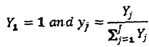 7 = 2, 3, ..., J
2- Rate-based mass transfer equation of each component j in the liquid phase
7 = 2, 3, ..., J
2- Rate-based mass transfer equation of each component j in the liquid phase
dc A
p=* / = 2, ..., J; /> = 1, ..., P (2) where iv is the rate of diffusion of component j and Rjp is the rate of generation of component j by the reactions p of the system of P reaction p= 1, P). uL is the superficial velocity of the liquid (volumetric flowrate divided by the column cross section area).
3- Energy balance equation of gas phase
Ft(moi, l) = l)7s y lCpJ I ) (dT G)/dz = - fi a,e (T¾ - Γτ£- )
(3)
where the heat transfer coefficient, ho, is obtained from dimensionless analogies such as the well-known Chilton-Colbum y-factor, or using various empirical formulas. According to Chilton-Colburn:
2 2
JD = St.Sc* and J» = StH. Pr?
Then
 where *s " is the thermal conductivity of the gas.
4- Energy balance equation of liquid phase uxl = 1)7- lc J 1 ) idTxV)fdz = +hxG axe - ΓΤΙ )
 (4)
where ^"i is the heat of vaporization of component j. It is noteworthy that in the ease of C02 capture with amines, the heat of vaporization will be applicable for one component only, i.e. water, in the desorber.
(4)
where ^"i is the heat of vaporization of component j. It is noteworthy that in the ease of C02 capture with amines, the heat of vaporization will be applicable for one component only, i.e. water, in the desorber.
5- pressure profile of the column

\d∑ oad*d tefdry ^'liquid (5) where

X/and G/are liquid and gas loading factors, respectively. is the dry-bed packing factor (sometimes called "Robbins factor") which is usually provided by manufacturers, est , - est 13 are constants.
The problem of integrated modeling and design compared with modeling only is the unavailability of column diameter and height. To solve the ordinary differential equations (ODEs), i.e. Eqs. (1), (2), (3), (4) and (5), the initial parameters must be available. This is whilst the properties of liquid at the bottom of the column are not available (temperature, concentrations and flowrate). To initiation of the solution, smart initial values (IVs) are used and the average values of gas and liquid parameters (temperatures and concentration)
are computed at the top and bottom of the column from where the physico-chemical properties (viscosities, densities thermal conductivities, surface tensions, heat of reaction, diffusivities specific heat) are computed using the rigorous equations detailed in Table 1 (see appendex). Once these parameters are computed, Eq. (6) is used to obtain the flood velocity. logYf! -0289CagFLVy - 1.081 logF^ - 1.682 (6) where

Having obtained the value of ?fi> the flux of gas at flooding ( ass, fi) is calculated by a relation given by

The packing factor, Fp, is usually given by manufacturers and when unavailable is
a-
F ——
approximated by p ?.a .
G
Then the design velocity ( ½ ) is calculated based on the method discussed earlier (70-85 c
% of u ). Having these, the column diameter is obtained.
The next step is to find the column height which will be obtained using the ODEs system. The finite difference (FD) method is used to solve the ODEs. The step size of Δζ is defined for column height and the equations are solved for every stage s as illustrated in the schematic of a packed column model structure. There are also numerous physico-chemical parameters (viscosities, densities, thermal conductivities, surface tensions, heat of reaction, diffusivities, specific heat, mass and heat transfer coefficients) required for solving the ODEs. Each and every of these physic-chemical properties are function of function of various parameters. The accurate values of these parameters are critical in the modeling.
The detailed equations of these properties are given in Table 1 (see appendix). These parameters are computed at every stage s of the column. As enhancement factor (E) and interfacial vapor pressure of the component have implicit functionality, a loop is used to find the both parameters. With all these the ODEs are solved for the first stage s - \. The order of equations is: concentration equation of gas, Eq. (I), concentration equation of liquid, Eq. (2), temperature of gas, Eq. (3), temperature of liquid, Eq. (4), and finally pressure drop, Eq. (5). Once these equations are solved their output will be used as IVs for the next stage s+l . The ODEs for every stage are solved, continuing until condition is reached when the value of the target component at stage s (Ym, *) becomes equal to the given value *re, out . This stage is s = S and the packing height of the column is Z = S x &z. At this point, if the output values match with the initial assumption, the design task is accomplished; otherwise, it is necessary to update the guess with the new values and proceed to the next iteration. Once the goal is achieved, the real packing height can be calculated from the results of the final run.
The overall pressure drop of the column is calculated by summation of the pressure drops
s in all stages (*=i ). If the overall pressure drop is higher than the desired value, then the packing type or size can be changed and another analysis carried out.
The desorber flow chart shows a further example embodiment of a part of the mathematical model of the solvent based carbon capture process detailing an integrated modelling and design methodology of a desorber column. The desorber model, though fundamentally similar to the absorber, has further complexity. Basically, the objective of the desorber is to heat the liquid in order to force the reverse kinetics to release the target component (C02). In the cases when the saturation temperature of solvent and solute are very different then part of the solvent mixture can be evaporated to provide the stripping fluid. For instance, MEA has a saturation temperature of 170.4 °C at atmospheric pressure, which is quite remote from that of water, being 100 °C. Therefore, part of the liquid reaching the bottom of column can be heated (reboiled) to a certain temperature to generate steam. Further to this the recycled iiquid, from the condenser can also be used for
steam generation as shown below in the schematic of a desorber. Reboiler pressure and temperature are among the most critical (if not the main) parameters in desorber design. The reboiler pressure should be enough to compensate for the pressure drop of the packed column and allow the gas phase (steam) to move up. That is the minimum requirement for reboiler pressure. However, high pressures are usually preferred for the desorber because of the intensity of the process and the ability to work at higher temperatures without fear of more liquid vaporization. However, the pressure has an upper limit, enforced by (1) the economics of the system, either capital expenditures (CAPEX) or operational expenditures (OPEX), and (2) the solvent degradation temperature ( De8}. Therefore, it is expected to have an optimum operating pressure based on any solvent used.
The reboiler temperature is more complex than the pressure. Theoretically, a higher desorber (reboiler) temperature will expedite the regeneration process. However, there is an upper bound for this temperature, enforced by process techno-economics and by two main issues: (1) a higher reboiler temperature means higher quality of utility steam, which increases the operating costs of the process; (2) high temperatures result in solvent degradation. Therefore, for any solvent there is a degradation temperature (T°es that the reboiler temperature should not exceed. As such, the reboiler temperature constraint can be written as
TRab < min(Tsat (P)l T!>*e) where Tsat(P) is obtained from flash vapor-liquid equilibrium calculations at pressure P. A simple Tsat(P) can be obtained from Raoult's law, given by
T*at(P) = ½>iv¾( ) +· (1 - >¾(P) in which xSoivmc is the molar fraction of the solvent in the solution. ^iSl-CP) and ^o P are the saturation temperatures of pure solvent and water at pressure P, respectively, which are usually presented by an Antoine equation.
The flowrate of the gas stream is another concern. Certainly, the objective is to use just enough steam to achieve the regeneration objective, as any extra steam will just add to
costs. The exit gas from the column top will contain mainly the target gas (C02) and steam. Obviously the partial pressure of the target gas (TG) should be less than the equilibrium partial pressure of the inlet liquid {(Pco* ^≤ Pco, @ a ~ avm \- Otherwise, reverse mass flow will occur, meaning that instead of desorbing the target component from the liquid, more TC will be absorbed. As such, the flow rate of steam at the bottom of the reboiler should be such that at the top of column the partial pressure of steam becomes greater than "p - Pco£a? t )". Moreover, the temperature of the gas at the top of the column should be higher than the inlet liquid temperature (¾r < T&tt ), to allow regeneration to initiate from the column top. It is therefore necessary that before desorber modeling the reboiler temperature is decided and fed into the program. The liquid temperature at the bottom of the column can also be set a few degrees below the reboiler temperature (¾t = ~ AT ).
Considering all these constraints, the gas flowrate is computed. Then the average physico- chemical properties are computed, from where the ¾» (and thus Υχ & °)? computed. If the assumptions have been selected inappropriately, it is possible that this value becomes meaningless or even negative. Therefore, it is necessary to check that the value is within the constraints; if it is not, the program should be updated with a new guess. The remainder of this algorithm is similar to that of the absorber, being calculation of the diameter, ODEs solution, and pressure drop computation.
The ODEs will solve until the loading of step s - S becomes simiiar to loading of inlet liquid.
The development of objective function may be related to external factors that can influence the economic viability of the operation of the solvent based carbon capture process. For example, the objective function may be the minimization of OPEX, minimization of CAPEX, maximization of internal rate of return (IRR), maximization of NPV, etc. As an example a formulation for NPV of cash flow is outlined below.
The net present value (JW ) is given by,

Where, TCX is the total capital expenditure o the PCC plant; CF, is cash flow at year /; r is the discount rate; M is number of plant construction years and N is the number of years for plant operation. The cash flow at year t €Ft ) is given by,
CFt = EBTt - iTlt + snTCX
Where EBTt is earning before tax at year /, 77, is the taxable income (He≥ ΕΒΤΛ τ is fractional tax, ε* represent depreciation fractional values for MACRS method (Modified Accelerated Cost Recovery System). The earnings before taxes at year t (EBT, ) is given by,
EBTt = Rt— OKt— £nTCX where, &t is the revenue ($) from captured C02 during year t, and OXt s the OPEX of PCC plant during year t.
The total CAPEX (TCX) and the annual OPEX (OX,} are both function of the operation and design variables and are represented as follows: = fo(X >X** Xf X*'Xs'Xt'X7'Xm'X*' Xi 'Xl l ' Xl»'Xl*' XlS'
Where Ψ is price escalation factor and,

C Raboileris)—

CXcenienssrts) = ί*&$· %t · ^?- ^ie* ^19· ^'ζι^
U2013/000978
- 23 -
CXfitat £x. - fs i' X*' Xi> ^β» ^IB · ^is« % ls» ^ 2o< ^2»)

/o are cost functions. With this the formulation for NPV of cash flow is complete.
The method described can be performed using a processing system, an example of which is shown in Figure 2. In particular, the processing system 100 generally includes at least one processor 102, or processing unit or plurality of processors, memory 104, at least one input device 106 and at least one output device 108, coupled together via a bus or group of buses 110. In certain embodiments, input device 106 and output device 108 could be the same device. An interface 112 can also be provided for coupling the processing system 100 to one or more peripheral devices, for example interface 112 could be a PCI card or PC card. At least one storage device 114 which houses at least one database 116 can also be provided. The memory 104 can be any form of memory device, for example, volatile or non-volatile memory, solid state storage devices, magnetic devices, etc. The processor 102 could include more than one distinct processing device, for example to handle different functions within the processing system 100.
Input device 106 receives input data 118 and can include, for example, a keyboard, a pointer device such as a pen-like device or a mouse, audio receiving device for voice controlled activation such as a microphone, data receiver or antenna such as a modem or wireless data adaptor, data acquisition card, etc. Input data 118 could come from different sources, for example keyboard instructions in conjunction with data received via a network. Output device 108 produces or generates output data 120 and can include, for example, a display device or monitor in which case output data 120 is visual, a printer in which case output data 120 is printed, a port for example a USB port, a peripheral component adaptor, a data transmitter or antenna such as a modem or wireless network adaptor, etc. Output data 120 could be distinct and derived from different output devices, for example a visual display on a monitor in conjunction with data transmitted to a
2013/000978
- 24 - network. A user could view data output, or an interpretation of the data output, on, for example, a monitor or using a printer. The storage device 114 can be any form of data or information storage means, for example, volatile or non-volatile memory, solid state storage devices, magnetic devices, etc.
In use, the processing system 100 is adapted to allow data or information to be stored in and or retrieved from, via wired or wireless communication means, the at least one database 116. The interface 112 may allow wired and/or wireless communication between the processing unit 102 and peripheral components that may serve a specialised purpose. The processor 102 receives instructions as input data 118 via input device 106 and can display processed results or other output to a user by utilising output device 108. More than one input device 106 and/or output device 108 can be provided. It should be appreciated that the processing system 100 may be any form of terminal, server, specialised hardware, or the like.
The processing system 100 may be a part of a networked communications system 200, as shown in Figure 3. Processing system 100 could connect to network 202, for example the Internet or a WAN. Input data 118 and output data 120 could be communicated to other devices via network 202. Other terminals, for example, thin client 204, further processing systems 206 and 208, notebook computer 210, mainframe computer 212, PDA 214, pen- based computer 216, server 218, etc., can be connected to network 202. A large variety of other types of terminals or configurations could be utilised. The transfer of information and/or data over network 202 can be achieved using wired communications means 220 or wireless communications means 222. Server 218 can facilitate the transfer of data between network 202 and one or more databases 224. Server 218 and one or more databases 224 provide an example of an information source.
Other networks may communicate with network 202. For example, telecommunications network 230 could facilitate the transfer of data between network 202 and mobile or cellular telephone 232 or a PDA-type device 234, by utilising wireless communication means 236 and receiving transmitting station 238. Satellite communications network 240
could communicate with satellite signal receiver 242 which receives data signals from satellite 244 which in turn is in remote communication with satellite signal transmitter 246. Terminals, for example further processing system 248, notebook computer 250 or satellite telephone 252, can thereby communicate with network 202. A local network 260, which for example may be a private network, LAN, etc., may also be connected to network 202. For example, network 202 could be connected with ethernet 262 which connects terminals 264, server 266 which controls the transfer of data to and/or from database 268, and printer 270. Various other types of networks could be utilised. The processing system 100 is adapted to communicate with other terminals, for example further processing systems 206, 208, by sending and receiving data, 118, 120, to and from the network 202, thereby facilitating possible communication with other components of the networked communications system 200. Thus, for example, the networks 202, 230, 240 may form part of, or be connected to, the Internet, in which case, the terminals 206, 212, 218, for example, may be web servers, Internet terminals or the like. The networks 202, 230, 240, 260 may be or form part of other communication networks, such as LAN, WAN, ethernet, token ring, FDDI ring, star, etc., networks, or mobile telephone networks, such as GSM, CDMA or 3G, etc., networks, and may be wholly or partially wired, including for example optical fibre, or wireless networks, depending on a particular implementation.
The processing system 100 may be configured by a computer readable medium including executable instructions in the form of a computer program. Upon execution of the computer program, the processing system 100 is configured to perform the method described above. The computer readable medium may be memory such as a hard drive of the processing system 100, or portable memory (CD, DVD, etc.) or the like.
In use, the user inputs via the input device 106 of the processing system 100 the information including percentage of carbon dioxide capture, composition of the source of gas, flow rate of the source of gas, and solvent type. This information is stored in memory
104 of the processing system 100 together with the mathematical model. This information are known parameters for the specific solvent based carbon capture process. The mathematical model is dependent upon the one or more design parameters and the one or more operational parameters.
The processing system 100 then determines the size and/or configuration of the solvent based carbon capture process. In particular, the determination step includes the processor 102 iteratively manipulating the value of one or more design parameters and one or more operational parameters of the solvent based carbon capture process in accordance with one or more objective functions that have been selected by the user. More specifically, the user is presented via the output device 108 of the processing system a list indicative of the one or more objective functions that can be applied by the processor 102 of the processing system 100 to iteratively manipulate the value of the one or more design parameters and the one or more operational parameters within the mathematical model until the one or more objective functions are optimised. By iteratively optimising the objective functions, the processor 102 is able to determine the size and/or configuration of the solvent based carbon capture process which meets the one or more objective functions. The determine the size and/or configuration of the solvent based carbon capture process can then be output via the output device 108. It will be appreciated that due to the complex nature of the optimisation process, such a technique cannot be performed manually in any feasible timeframe and thus an automated process using the processing system is quite advantageous in achieving this outcome.
The processing system 1 0 preferably has stored in memory optimisation software for manipulating the one or more design parameters and the one or more operational parameters in order to optimise the objective functions. Such optimisation software may apply a global optimisation technique which can include techniques such as deterministic methods, stochastic methods, or heuristics and metaheuristics.
It will be appreciated that a non-transient computer readable medium can be provided for configuring the processing system to perform the described method.
The present invention will become better understood from the following example of a preferred but non-limiting embodiment thereof: Example 1
The following example involves the design and/or configuration of a solvent based carbon capture process for use with a 300 MWe coal-fired power plant in Australia burning pulverized black coal. The plant uses black coal with 25% ash, 8% moisture, and dry-ash-free (DAF) composition of 83.3% carbon, 5.4% hydrogen, 1.9% nitrogen, 0.6% sulfur, and 8.8% oxygen. The power plant emits 12260 mol/s (353.3 kg s) of flue gas when operating at full capacity. The flue gas composition is 13.0 vol% (19.8 wt%) C02, 70.37% N2, 13.52% ¾0, 3.11% (¼ and ppm level of SOx and NOx. The SOx and NOx are removed from the flue gas prior to the emission entering into the proposed solvent based carbon capture process. As the temperature of flue gas is usually above 100 °C, and as the optimal operation of the absorber is far below 100 °C (40-60 °C for MEA), the flue gas will be required to be cooled to a temperature, ¾t , prior to entering the absorber.
The example objective is to design and/or configure a solvent based carbon capture process with base-case capacity or the ability to capture 90% of the C02 tn the flue gas.
Absorber
By running the model as discussed above, the results of the first run of the program showed that the size of an absorber operating under the above-mentioned base-case conditions would be very large, with a diameter in the order of 20 meters. For this reason it was decided to design two absorbers of similar sizes to work in parallel. Therefore, the
inlet flowrate of each absorber would be half of the total fiowrate i.e. 6130 mol/s (176.65 kg s).
The temperature of 50 °C (¾t) was used for the inlet flue gas. Together with this inlet temperature, the remainder of the inlet gas information is known.
The quantity of C02 in the outlet gas stream is calculated as having the 90% capture objective. Estimate values are made for the composition of other gas components and also the outlet gas temperature. The inlet liquid temperature is taken as 53 °C (a few degrees higher than inlet gas temperature). The C02 loading of liquid is taken as 0.2 and 0.45 at inlet and outlet of column, respectively. With these loadings, the concentrations of components are computed from where the outlet temperature of the liquid is calculated.
Two-inch (50 mm) ceramic berl saddle packing was chosen as a packing with specific area of 105 m'1, porosity of 0.72, packing factor of 150 (Fv ) and dry bed packing factor (Fpd ) of 102. The pressure at the column bottom was designed to be 1.1 bar. The gas should leave the column, on top, at a pressure greater than or equal to atmospheric pressure. Therefore, the maximum allowable pressure drop over the column is about 0.1 bar.
With the above data, the model outlined above was solved and converged in just the second iteration. In this example, the column has a diameter of 9.80 m and length of 18.4 m. For this design, liquid with the flowrate of 0.573 m3/s or 25112 mol s is required. This translates to Lmoi Gmoi of 4.1. The diameter design was taken based on gas velocity being 80% of that in flooding (2.11 m/s vs. 2.64 m s). That velocity guarantees that the inlet gas with pressure of 1.1 bar will leave the column at above atmospheric pressure (not below). Figure 1-1 illustrates the profiles of pressure and pressure-drop over column height. The gas enters the column bottom at 1.1 bar and exits from the top at 1.0148 bar, being slightly above atmospheric pressure.

Figure 1-1: Profile of flue gas pressure and pressure-drop over absorber column height, using berl saddle 50 mm and at design velocity of 80% flooding. The liquid inlet and outlet loadings are 0.2 and 0.45 with the carbon capture target of 90%. The inlet liquid temperature is 53 °C and the gas temperature is 50 °C.
Figure 1-2 shows the temperature profile of gas and liquid over the column height. Once the lean liquid enters the column from top (at 326.15 K), it starts reacting with the flue gas as the gas progresses from the bottom upward. As the reaction is exothermic, the temperature increases down to the bottom of the column. The reduction in temperature in a small section at the bottom of column is due to the gas entering the column at lower temperature. The so-called "rich" liquid leaves the column from the bottom at the temperature of ¾i = 336.15 K (63 °C) while the clean flue gas is emitted to the atmosphere from the top of the column at ri = 326.31 K (63.16 °C).
The concentration profiles of the main components of the liquid are illustrated in Figure 1- 3. The 30 wt% MEA solvent with a loading of 0.2 enters the column height at a concentration of 3.0 kmol/ m3. Moving down the height of the column it reacts with C02 and the concentration of pure MEA is decreased until the value of 0.5 kmol/m3 is reached at the bottom of the column. At the same time the composition of reaction products such as carbamate increases from an initial value of 1.0 kmol/m3 to 2.2 kmol/ m3 at the bottom of the column until the rich liquid leaves the column towards the regeneration unit.
saddle 50 and 0.45

Figure 1-3: Concentration profiles of MEA and MEACOO" of liquid temperatures over absorber column height when the liquid inlet and outlet loadings are 0.2 and 0.45 respectively.
Figure 1-4 illustrates the profile of loading of C02 in the liquid (hereinafter referred to as "loading"). The liquid enters the column with a loading of ° - 0.20 (lean liquid) and
leaves with a loading of aSsi - 0.45 (rich liquid). The figure illustrates how the loading changes over the column and how it corresponds with the rate of C02 capture. The importance of the figure is that if the outlet loading is fixed at 0.45, and all the design and operating parameters are fixed at the values discussed earlier, then to capture 90% of the C02 from the flue gas (the design objective), the C02 loading of the inlet liquid must be 0.2. However, to capture 80% of the C02, the inlet loading of 0.23 and column height of 14.0 meter will achieve the goal. Similarly, to capturing only 50% of the C02, the corresponding inlet loading is 0.31 and a column height of 8.2 m will satisfy the goal.

Column height from bottom (m)
Figure 1-4: Relation between inlet liquid loading and capture rate using berl saddle 50 mm packing and at design velocity of 80% flooding for all examples; the base case design diameter of 9.8 m, flue gas with 13% C<¼.
The next profiles presented are the equilibrium, interface and operating curves. The assumption of equilibrium-based column modeling is that at every stage, the gas and liquid phases reach their equilibrium or a percentage of it. In the rate-based modeling, however, the gas-liquid mass transfer rate is function of numerous parameters which were earlier discussed. The gas-liquid equilibrium is therefore just one of the (limiting) conditions which might occur. Figure 1-5 illustrates the profiles of C02 at equilibrium, interface and operation over (a) column height, and (b) loading. The flue gas enters the column with the
C02 fraction of 13% and leaves it with β = 90% of the C02 having been captured (outlet fraction of 0.0131). From fundamental separation textbooks it is known that for absorption the operating line is above the equilibrium line and the difference between these two curves is an indication of the mass transfer driving force. It is of interest that the operating curve is remote from equilibrium. From these triple curves that the author believes have not been previously presented, reverse-engineering is possible to present the corresponding mass transfer efficiency over the column height or loading. Figure l-5c illustrates the efficiency profile and implies that the mass transfer rate efficiency is maximum 10.3% at the top of column and reaches 3.14% at the bottom of the column when C02 loading is high.


CO. loading
Figure 1-5: Profiles of C02 equilibrium, interface and operation over (a) the column height, and (b) loading. Figure (c) is the corresponding efficiency (%). It would be of interest to study the mass transfer efficiency (Figure 4-1 lc) along with the enhancement factor. Figure 1-6 illustrates the enhancement factor over the column height, being at its lowest value of 25.9 at the bottom of the column and at its highest value of 85.3 at the top of the column. Therefore the mass transfer efficiency is identical to the enhancement factor.

Column height from bottom (m)
Figure 1-6: Profile of mass transfer enhancement factor (due to solvent and C02 reaction) over the absorber column height.
Parametric analysis of absorber Parametric analysis is performed over some important parameters to quantitatively evaluate the impact of key parameters in the design and performance of the absorber column.
Impact of packing type and size The impact of six different packing types on column sizing was investigated. The results are illustrated in Figure 1-7. It is clear from the figures that packing type has a notable impact on both operating and design parameters. Although all the given conditions except packing type are similar, the application of 50 mm berl saddle packing results in an absorber column with size of 9.8 m diameter and 18.4 m height along with a total pressure drop of 8.5 kPa over the column. The second best option is a 50 mm Intalex saddle application, which results in a column with diameter of 9.5 m and height of 18.2 m. However, it has a greater pressure drop of 14.35 kPa. Therefore, if this packing is used the column pressure at the bottom should be above 1.157 bar. It is of interest that a 75 mm raschig ring results in a relatively tall column with diameter of 9.3 m and height of 33 m. This is not the only difference; it further results in a notable pressure drop of 66.19 kPa over the column. Therefore, the significant impact of packing type on column design is demonstrated, and based on the few examples investigated a 50 mm berl saddle was selected as a preferred packing type.

Column height from bottom (m)
Figure J -7: Impact of packing type/properties on column size and pressure drop at design velocity of 80% flooding for all examples where the flue gas inlet pressure is l.l bar.
Impact of gas velocity/flux
As discussed earlier, in order to prevent flooding, the gas velocity is typically designed to be in the conservative range of about 70-85% of flooding velocity. Here the impact of the design velocity on both column design and performance is investigated. Seven different velocities are used, i.e. 70%, 72.5%, 75%, 77.5%, 80%, 82.5% and 85% of the flooding velocity. The results are given in Figure 1-8. It is evident that an increase of velocity has a slight impact on column size, in that it slightly increases height and slightly decreases column diameter. For instance, the design velocity of 70% results in a column with diameter of 10.5 m and height of 16.6 m, whereas at 85%, the size becomes 9.5 m diameter (9.5% decrease) and 19.2 m height (15.7% increase). The pressure drop for the 70% scenario will be 5.30 kPa through the packing height, while for the 85% scenario it will be 10.80 kPa, almost double of that for 70%.
If a higher velocity is selected, it will result in higher pressure drop and the outlet pressure will be less than atmospheric pressure. This means that a higher inlet pressure (higher than 1.1 bar) would be required, translating to higher operating costs.

Figure 1-8: Impact of design velocity on column size and pressure profile.
Impact of gas/liquid ratio
The gas/liquid flowrates are also among the key parameters of column design and operation. Their impact on at least the operating cost of the solvent based carbon capture process (OPEX) is non-trivial. For the base model, when the the liquid loadings at 0.2 and 0.45 are fixed, the corresponding Lmoi/Gmoi ratio becomes 4.10. The same example has been worked with the same given parameters, and studying the impact of liquid flow rate on column design and operating parameters. The column diameter was fixed at 9.8 m for all parameters so that the impact on design was revealed via the column height. Figure 1-9 illustrates the impact of seven different liquid flowrates (flue gas flowrate, Gmoi, being fixed for all cases) on process. The outlet liquid loading is fixed at 0.45 and the inlet loading is obtained by the model. It is evident from the figure that an increase in liquid flowrate results in an increase in column height and inlet liquid loading. To facilitate
quantitative discussion, Table 1-1 lists some of the key parameters for each of the seven scenarios. For instance, whereas for flowrate of 17800.54 mol/s {Lmo^Gmoi ~ 2.87) the column height is 17.8 m, it increases to 18.4 m at Lmoi/Gmoi = 4.10 and to 22.8 m at LmoJGmoi = 8.19. The inlet liquid loading for Lm0/Gmoi - 2.87 is 0.095 and it becomes 0.200 for Lmo/Gmoi = 4.10 and 0.326 for Lmo Gmoi = 8.19. The implication of these values is that for a certain C02 capture objective (e.g. 90% of flue gas), when the liquid flowrate is increased, then lower inlet loading is required (considering a fixed outlet loading).

Column height from bottom (m)
Figure 1-9: Profile of C(¾ loading along the column length and its impact on column height at fixed diameter of 9.8 m.
Table 1-1: Design output data for various L/G studies.

3.48 0.157 -»0.45 336.15 324.22 0.0128 9.8 18 1.0231 7.69 487.66
=21567.47
1^=25334.68 4.1» 0.200 -»0,45 336.15 326.1 0.0126 9.8 18.4 1.0143 8.57 573.72
4.71 0.2333 -»0.45 336.15 327.62 0.0126 9.8 18.8 1.0043 9.57 659.78

533 0.2586 -»0.45 336.15 328.71 0.0127 9.8 19.2 0.9928 10.72 745.84
=32867.96
Laol =1.5 Lmtf.hisc 6.15 0.2840 -»0.45 336.15 329.80 0.0127 9.8 20 0.9725 12.75 860.58
=37890.47
Led =2.0 LmMnx 8.19 0.3257 -»0.45 336.15 331.53 0.0128 9.8 22.8 0.8814 21.86 1147.44
=50446.1
To capture 90% of C02 under the given condition Lmo/Gmoj ~ 4.10 is required. With inlet and outlet loadings fixed, it is possible to use lower Lmo Gmoi and study the impact on the rate of carbon capture. Figure 1-10 illustrates the results of six different Wo Gmo/ scenarios within the range of 2.05 to 4.10. The details of the results are given in Table 1-2. It is evident that when Lm Gmoi is 4.10 the rate of capture is 90%, but with reduction in Lmo Gmoi value the capture rate decreases until it reaches the lowest value of 46.55% at Lmoi/Gmoi =2.05. However, reduction of
 also reduces the column height requirement. While the capture of 90% COa requires a column with height of 18.4 m, only 7.6 m column height is required to capture 46% of C<½ when Lmo Gmoi is 2.05.

Figure 1-10: Impact of inlet liquid flowrate on column size and carbon capture rate using erl saddle 50 mm packing and at design velocity of 80% flooding for all examples; the base case design diameter of 9.8 m is fixed for all the scenarios. The liquid inlet and outlet alpha is fixed at 0.2 and 0.45.
Table 1-2: Design output data for various L G studies.

0.200
3.69 336.15 326.43 0.0257 80.3 9.8 14 1.0372 628 516.35
=22797.98 -»0.45
0200
328 336.15 326.44 0.0364 72,0 9.8 1L8 1.0492 5.08 458198
=2«265Λ8 -»0.45
0.200
2.87 336.15 326.40 0.0469 63.95 9.8 102 1.0580 4.20 401.60
=17734.63 ->0.45
200
2.46 336.15 326.49 0.0581 5528 98 8.8 1.0652 3.48 344.23
=15201.88 -»045
0200
2.05 336.15 326.65 0.0695 46.55 9.8 7.6 1.0712 2.88 286.86
«12669.12 ->0.45
Impact of gas/liquid temperature
The absorption process is highly exothermic. Therefore the application of correct liquid and gas temperatures was found to be critical in process design and operation. Here the individual impacts of inlet liquid temperature (TLt ) and inlet flue gas temperature
 are studied. For analysis of the inlet liquid temperature, inlet flue gas temperature is maintained at 323.15 (50 °C) and liquids with wide temperature ranges are used. Figure 1-11 illustrates the gas/liquid temperature profiles for four different scenarios. The other details of these scenarios are given in Table 1-3. It is evident that temperature has some small impact on column diameter, which may stem from physical expansion of fluids at high temperatures. However, the effect of liquid temperature on column height is interesting. At the low temperature of 313.15 K (40 °C), the column height is 21.2 m. When the temperature is increased the column height reduces to a minimum, from where it increases again at higher temperatures.

10 15
Column height from bottom (m)
Figure 1-11: Impact of inlet liquid temperature on column size and pressure drop using berl saddle 50 mm packing and at design velocity of 80% flooding for all examples.
Table 1-3: Design output data for various inlet liquid temperatures studies.

313.17 32435 323.15 0.200 -W.4J m 9.77 21.2 1.0029 9.71 573.72 25334.75 4.10
323.13 333.35 323.15 0.200 -M.4S 0.0129 9.80 18.6 1.0142 8.58 573.72 25334.18 4.10
328.14 337.9 323.15 0.200 -»0.45 0.0128 9.81 18.2 1.0153 8.47 573.72 2533424 4.10
333.21 342.5 323.15 0.200 -»0.45 0.0129 9.83 19.2 1.0087 9.13 573.72 25334.08 4.10
To further analyse the impact of inlet liquid temperature on column height, the column diameter was fixed at 9.8 m and a number of runs were performed over numerous inlet
liquid temperatures. The profile is illustrated in Figure 1-12. It is evident that under the given conditions, the minimum column height is at an inlet liquid temperature of about 327.85 K (54.7 °C).

Inlet liquid temperature (C)
Figure 1-12: Impact of inlet liquid temperature on column size using faeri saddle 50 nun packing and at design velocity of 80% flooding for all examples; diameter is fixed at 9.8 m.
There is also another important issue for selection of inlet liquid temperature; as the temperature increases, the equilibrium partial pressure of C02 increases. This reduces the mass transfer driving force. The limiting condition can occur when the equilibrium partial pressure of C02 at the bottom of the column becomes equal to or higher than the partial pressure of the inlet flue gas. To illustrate this, the equilibrium, interface and operating profiles of the column, over loading, are shown at two different temperatures (Figure 1- 13). At the low liquid temperature of 40 °C it is evident that the interface and operating curves are well above the equilibrium curve, indicating that there is a good driving force for mass transfer (Figure l-13a). However, as the temperature increases the equilibrium curve moves upwards and closer to the other two curves, resulting in the reduction of mass transfer driving force. For the scenario with inlet liquid temperature of 62 °C, when the
liquid leaves the bottom of the column at a loading of 0.45 and temperature of 71.2 °C, its equilibrium C02 fraction is equal to that of the inlet flue gas. This means that if, under the given conditions, an inlet liquid temperature higher than 62 °C is used, part of the bottom of the column will dysfunction. Therefore, consideration of the upper bound for inlet liquid temperature is necessary for robust/optimal column design and operation. One approach for dealing with high-temperature liquid is to select lower loadings at the column outlet, e.g. «« < °-45 for the above scenario.


C02 loading
Figure 1-13: Impact of inlet liquid temperature on equilibrium, interface and operating curves at (a) 40 °C and (b) 62 "C using bed saddle 50 mm packing and at design velocity of 80% flooding for all examples; diameter is fixed at 9.8 m and PM = 1.1 bar.
Similarly, a parametric analysis was performed on the impact of flue gas temperature on absorber performance. It was noted that, compared with liquid temperature, the flue gas temperature has less impact on either operating or design variables. Table 1-3 lists the results for five different flue gas temperatures (40 °C, 50 °C, 60 °C, 70 °C, 80 °C) while the inlet liquid temperature is fixed at 53 °C. With increase in the temperature, the column diameter increases slightly (around 1% over a 40 degree increase in temperature). The pressure drop also decreases slightly. To maintain a similar performance when the inlet flue gas temperature increases, the column requires the inlet liquid temperature to be low or the outlet liquid temperature to be high. In this example, when for all scenarios the outlet liquid temperatures are fixed at 63 °C (336.15 ), by an increase in the inlet flue gas temperatures the inlet liquid temperature decreases. As is evident from the table, for inlet gas temperatures of 40 °C the inlet liquid temperature is 54 °C (327.13 K), whereas it decreases by around 7% to 50.2 °C (323.36 K) when the inlet gas temperature reaches 80 °C. It can be concluded, therefore, that absorber design and operation are much more sensitive to inlet liquid temperature than to inlet gas temperature, and this can be linked physico- chemically with the higher specific heat capacity of liquid compared with gas.
Table 1-3: Design output data for various inlet liquid temperature studies.
* lit * jet Tout „ &s „Abs , D z Pout AP QL Lnwl/Gmol
(°C> "int ^ " out■
< K> (m) (m) (-»<·) (kPa) (lit s) (mol/s)
40 327.13 336,15 020 -»0.45 0.0126 9.78 18.4 1.0131 8.69 573,72 25334.74 4.10
50 326.18 336.15 020 -»0.45 0.0126 9.81 !8.4 1.0148 8.52 573.72 25334.78 4.10
60 325.24 336.15 O.2O-»0.45 0.0126 9.83 18.4 1.0163 8.37 573.72 25334.71 4.10
70 324.30 336.15 0.20 ->0.45 0.0127 9.86 18.4 1.0177 8.23 573.72 25334.55 4.10
80 323.36 336.15 0.20-»0.45 0.0128 9.88 18.4 1.0189 8.11 573.72 253343 4.10
Desorber
The rich liquid coming from the absorber is the feed to the desorber. Based on the base- case design of the absorber, the liquid enters the absorber with the flowrate of 25111.85 mol/s (0.573 m3/s) and after physico-chemical interaction with flue gas leaves the column
bottom rich with C02 loading of 0.45. The objective is to purify the liquid to the extent that it reaches the lean liquid loading predefined by the design as 0.20. As discussed earlier, these loadings may be any desired values selected by design.
As discussed in the absorber section, the design condition enforced selection of two absorbers. Therefore, here it is desired to mix the rich liquids from both absorbers and send them to a single desorber unless the design suggests application of more than one desorber. As such the inlet liquid flowrate for desorber design is about 1.146 m3/s (1220.4 kg s).
The rich liquid is assumed to be heated to 103 °C through heat exchange with the lean amine recycling back from desorber to absorber. It is expected that during this temperature rise some desorption occurs in the heat exchanger and the loading decreases slightly. For ease of analysis it is assumed that the rich amine enters the desorber at the same loading as it leaves the absorber. The most critical techno-economical parameter in the desorber column design is the steam (referred to as gas) stream. The gas stream is assumed to enter the column at 126 °C, which is the temperature of the reboiler. Unlike many other studies that reboil part of the effluent liquid from the desorber (lean liquid) to generate steam and use the recycled water (from the condenser) as wash- ater at the top of the column, the preference here is not to use condenser water for the water- washing task. Water-washing is necessary for the absorber column as it reduces the amount of liquid droplets in the emitted gas and thus reduces the rate of MEA loss. However, the effluent gas from the desorber column is mainly water and C02, and the gas stream moves towards the condenser where liquid components can be eliminated by cooling. Therefore, the application of a mechanical mesh at the top of the column may suffice. On this basis, the condensed recycled water from the condenser (being a few degrees below its saturation temperature) is used for reboiling and generating steam. Then the remaining amount of steam required is supplied by reboiling a portion of lean liquid. The significant advantages of this configuration are (1) energy efficiency as a result of better application of recycled water, (2) prevention of salt formation by solvent reboiling, and (3) most importantly, application of steam with a lower C02 concentration (compared
with the case of generating 100% of the steam from solvent reboiling) results in a larger mass transfer driving force and thus higher system efficiency.
A desorber column should operate at pressure in the range of 1.7-2.5 bar. In this example pressure of 1.7 bar is used, but later a parametric study of pressure is presented. With these given parameters, with the selected 50 mm berl saddle packing type and the design velocity of 70% the design model outlined above is solved for the desorber. The outcome is a column with diameter of 10.53 m and height of 15.8 m. This implies that one column is sufficient and there is no need for the use of two or more desorber columns. For this design, a gas stream with inlet flowrate of 8499.2 mol/s (160.0 kg/s) is required translating to the Lmo Gmoi of 5.80. The C02 concentration (mole fraction) of the gas under the given condition is 0.031 at the bottom of the column and 0.203 at the outlet of the column (towards the condenser).
The condenser temperature depends on the required C02 purity. When a higher C02 purity is required, the separated C02 may undergo other dehydration processes (e.g., Glycol system or molecular sieves). This is required when the captured C0 will be sent by pipeline to remote places for underground sequestration. In such cases the existence of water in the C02 stream can result in the formation of hydrates and thus erosion of the pipeline or compressors. Therefore, the condenser temperature selected depends on downstream application of the captured CC½ and technically is defined by VLE formulations. Reducing the gas temperature down to its bubble-point will separate almost all of the water, but at the cost of higher cooling utility expenses. In this analysis for the given example, a condenser temperature of 80 °C is used. The reboiler duty for the given scenario is 6.04 MJ/kg-C02.
Figure 1-14 illustrates the pressure and pressure-drop profiles over the desorber column bed. The pressure drop over the column is 8.27 kPa, meaning that the inlet gas with pressure of 1.7 bar leaves the column to the desorber at 1.617 bar.

Figure 1-14: Profile of gas pressure and pressure drop over desorber column height, using berl saddle 50 mm packing and at design velocity of 70% flooding. The liquid inlet and outlet loadings are 0.45 and 0.20. The inlet liquid temperature is 103 °C and the steam temperature is 126 "C.
Figure 1-15 shows the temperature profiles of gas and liquid over the column. The gas enters the bottom of the column at 399.15 K (126 °C) and, while moving upward in the column towards the condenser, it passes its heat to the liquid stream and cools/condenses until leaving the column at temperature 380.22 (107 °C). The inlet liquid enters the top of the column at 379.15 K (106 °C) and during movement towards the bottom, takes energy from gas for C02 regeneration. Its temperature is increased through the column and it reaches the bottom at the temperature of 391.6 K (118.5 °C).
Column height from bottom (m)
Figure 1-15: Gas and liquid temperature profile over column height using berl saddle 50 mm packing and at design velocity of 70% floodin for all examples; the liquid inlet and outlet loadings are fixed at 0.45 and 0.2, respectively. The Met liquid temperature is 103 "C and the steam temperature is 126 "C.
Figure 1-16 shows the profiles of MEA and carbamate over the column. The rich liquid with low concentration of free MEA (0.5 kmol m3) and high concentration of bounded MEA such as carbamate (2.2 kmol/m3) enters the top of the column and regenerates through downward movement in the column when the C02 bounds are broken, the concentration of bounded ions decreases, and free MEA increases. The lean liquid, with MEA of about 3 kmol/m3 and carbamate of about 1 kmol/m3, leaves the column towards the absorber (after heat exchange with the rich liquid coming from the absorber).

Column height from bottom (m)
Figure 1-16: Profiles of liquid components over column height using berl saddle 50 mm packing and at desig velocity of 70% flooding for ail examples; the liquid inlet and outlet loadings are fixed at 0.45 and 0.2, respectively. The inlet liquid temperature is 103 °C and the steam temperature is 126 °C.
Figure 1-17 illustrates the three curves, i.e. operating, interface and equilibrium fraction of C02 over the column height and also with respect to loading of liquid. It is evident that the equilibrium and operating line are very close at loadings of about 0.30-0.35. From the figure it is clear why a higher C02 concentration in effluent gas is not possible under the condition that inlet liquid has a loading of 0.45 and an outlet loading of 0.2. From the figure, if outlet loadings higher than 0.2 are assumed then the operating line has the potential to move up from right-hand side, translating to outlet gas with a higher content of C02. hi the parametric analysis section this issue is elaborated.

Column height from bottom (m)
Figure 1-17: Profiles of operating, interface and equilibrium concentration of COz over column height and loading using berl saddle 50 mm packing and at design velocity of 70% flooding for all examples; the liquid inlet and outlet loadings are fixed at 0.45 and 0.2, respectively. The inlet liquid temperature is 103 °C and the steam temperature is 126 °C.
Parametric analysis for desorber
The base-case scenario studied earlier resulted in a column with packing size of 10.53 m diameter and 15.8 m height. Under this scenario the Lmo Gmoi is about 5.80 and the gas exiting from the desorber has C02 molar fraction of about 0.20. The overall reboiler duty is 6.04 MJ/kg-C02. The reboiler duty is huge: a normal coal-fired power plant produces high quantity of C02, in the range of a few hundred tonnes per hour, and requires a huge amount of steam to satisfy this obligation. It is critical, therefore, to find the optimum condition under which the reboiler duty is mimmized.
The impact of packing type was investigated in the section on absorber column design, and was also found to apply to the desorber.
Impact of gas velocity/flux As with absorber, the impact of design velocity on column size and performance was studied. Figure 1-18 illustrates the profiles of column diameter and pressure drop over the design velocities in the range of 70% to 85% of flooding velocity. The detailed results for each velocity scenario are given in Table 1-5. As expected, the increase of velocity decreases the column diameter. However, the pressure drop is notably elevated with an increase of design velocity. For instance, at the design velocity of 70%, the column diameter is 10.53 m and 15.8 m, and the pressure drop is 8.27 kPa. When the velocity reaches 85%, the diameter is 9.39 m, with a 10.8% decrease. Meanwhile the corresponding pressure drop becomes 23.43 kPa, being 183.3% higher than that for the 70% scenario. Velocity has affects the reboiler duty and the column height. Therefore, selection of the optimal design velocity may be said to be a compromise between capital expenditure CAPEX (size) and operating expenditure OPEX (pressure drop).

% of flooding velocity
Figure 1-18: Impact of gas design velocity on column size and pressure drop, using beri saddle 50 mm packing for all examples; the liquid inlet and outlet loadings are fixed at 0.45 and 0.2, respectively.
Table 1-5: Impact of design velocity on desorber column design and performance.
% fl t> Z P..
ood rs 7* £«* Δ,
(Kl m ( ) («9 «». ( ) ( K) (tar) (?* <«%> L.. (mol/i) GM (moVl) G_ Q
(MJfla-CO,!
70.0 399:15 376.26 378,1134 391:5 0:45 0.2 0:20 · 16.53 15,8» 1.617S34 8.2666 11*7:44 47703.20 8499:1 5.80 6,04
71,5 399. IS 376.23 378.043 391.5 0.45 0.2 0.21 10.29 17,40 1.596769 10.3231 1147.44 47704.25 8350.76 S.9I 5.93
75.8 399.15 375.80 377.8002 391.5 0.45 0.2 o:2i 10:12 17.20 1.583499 11:6501 M47.4 47662:06 8150176 591 5.77
77.5 399.15 376.03 377.9424 391.5 0.45 0.2 0.21 9.96 16.80 1.569293 13.0707 1147.44 47685.46 8350.76 5,91 S.8
«0.0 399.15 375.88 377.8337 391.5 0.45 0Λ1 9.76 17.40 1.542459 15.7541 U47.44 47673.09 8254.64 5.97 5:74
«2.5 399.15 376.15 377.9972 391.5 0.45 0.2 0.21 9.60 17.20 1.516767 18.3233 1147.44 47701.62 8207,40 6.01 5.82
S5.0 399.15 375.87 377.809S 391.5 0.4S 0.2 0.22 9,39 18,20 1.465738 23,4262 1147.44 47679.97 8023.75 6.15 5.60
Impact of gas/liquid ratio The base-case scenario studied earlier resulted in Lm0/Gmoi of about 5.80. A scenario study was performed over various ranges of Lmoi/Gmoi. Figure 1-18 illustrates the results and shows how the changes of Lm0/Gmoi values impact on the reboiler duty, C02 fraction of the outlet gas and the column height. The other operating and design specifications of the scenarios are given in Table 1-6. As evident in Figure 1-18a, with the increase of the Lmo Gmoi, or in other words with the decrease of gas flowrate, the reboiler duty expectedly
decreases. This results in an increase in the concentration of C02 in the outlet gas. For instance, for Lmo/Gmoi of 5.73 the reboiler duty is 7.61 MJ kg-C02 and the C02 fraction is 0.15, whereas at Lmo/Gmoi of 13.17 the values become 3.21 MJ kg-C02 and 0.36, respectively. If just these three parameters were the basis for decision, it could be concluded that the higher the Lmo/Gmoi (the lower the gas flowrate Gmoi), the better. The gas flow rate could be designed as low as possible, with a lower bound such that the CO2 fraction at the column top does not reach or exceed the equilibrium fraction of C02 for inlet rich liquid. However, from the column size graphing (Figure 4-26b), it is evident that although the reboiler duty "decreases with an increase in Lmo/Gmoi, the column height meanwhile notably increases. The height for Lmo Gmoi - 5.73 is 2.20 m, but it skyrockets to 67.40 m at Lmo/Gmoi = 13.17. The pressure drop also accordingly increases with height elevation.
The column diameter is a direct function of fluid flowrate. With decline of Gmoi (increase of Lmo Gmoi ), the column diameter also decreases. The diameter at Lmo/Gmoi = 5.73 is 10.67 m wealst it is 8.29 m at Lmo/Gmoi = 13.17 m.
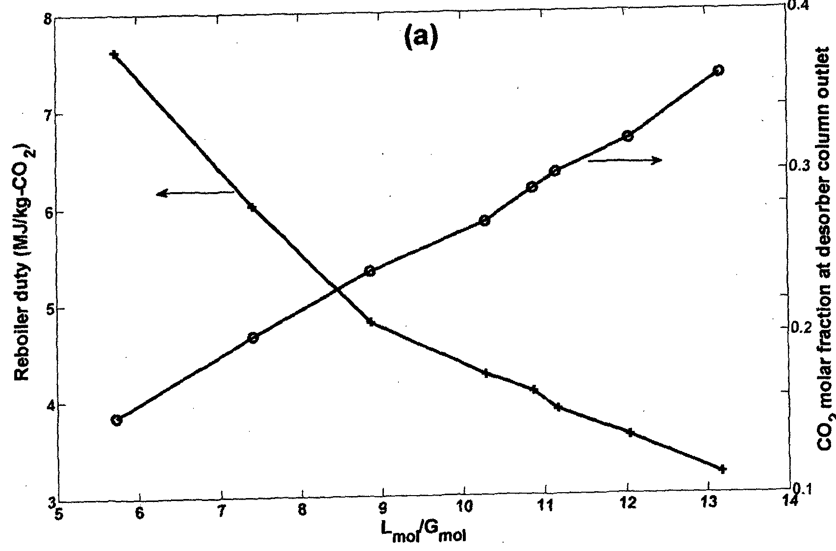

Figare 1-18: Impact of liquid-gas ratio (imo Cmo/) on (a) reboiier duty and C(¼ concentration, and (b) column size, using berl saddle 50 mm packing and at design velocity of 70% flooding for all examples; the liquid inlet and outlet loadings are fixed at 0.45 and 0.2, respectively. The inlet steam temperature is 126 °C.
Table 4-6: Impact of inlet gas (steam) flowrate on column design and performance.

4095.08 48054,82 no* 399.15 378.60 379.7798 . 391.5 0.45 0.25 0.32 8.50 37.40 1.527343 17.2657 1147.44 3.60 um 4804S«> 399.15 378.66 379:9098 ,391.5 0.45 0.25 030 8.69 1800 1.61S5J9 8Λ421 1147.44 3,88
4533.85 48070.45 10.(8 399.15 378.94 380.1494 391.5 0;45 0.25 0.29 8.76 13.60 1.639273 6.0727 1147.44 4.07
4794.U 48044.89 399.15 378.83 ' 3802579 391.5 <Ws 0.25 0.27 890 8.80 (.660806 3.9194 1147,44 4.25
5559.77 47985.16 uei 399.15 37S.S3 380.6433 391.5 0.45 0;25 0.24 9.29 5.20 1.676627 2.3373 1147,44 4.80
6658.68 48418.90 7M 399.15 37939 3819072 391.5 0.45 0.25 OJO 9.82 3.40 1.684438 1.5562 1147.44 6.01
8604.87 47944.97 5.73 399.15 379.41 383.5008' 391.5 0.45 0.25 0.15 10.67 2.20 1.68972 1.0280 1 147.44 7.61
To further analyze the reality behind the competitive relation of height and Lmoi/Gmoi the operating, interface and equilibrium profiles of six different LmoJGmoi scenarios are illustrated. At high Lm Gmoi (or low Gmoi values), the concentration of C02 in the gas phase increases and as a result the driving force between gas and liquid decreases. As evident in Figure I -19a, in the middle part of the figure all three curves almost touch each other, indicating that the column is operating at its lowest efficiency. This results in a
notable increase in column height. With a decrease of Zmo G (or increase of Gmo/), the concentration of€02 in the gas stream reduces and thus the driving force between gas and liquid increases. This is easily observed through Figure I-I9a-f.

Figure 1-19: Impact of Zm<) ( on operating, interface and equilibrium curves, using berl saddle 50 mm packing and at design velocity of 70% flooding for all examples; the liquid inlet and outlet loadings are fixed at 0.45 and 0.25, respectively. The inlet steam temperature is 126 °C.
Therefore, a high Gmol or low Lmo Gmoi is required to enhance the mass transfer driving force and improve the performance of the column, with concurrent costs in higher reboiler duty and higher column diameter. The minimization of reboiler duty is linked with column size and the selection of correct values requires a techno-economic study that includes both CAPEX and OPEX parameters.
Impact of gas/liquid temperature
The desorber performance is based on heat transfer from gas phase to liquid phase and breaking the reaction of the solvent with the target component and stripping it out of the liquid. Therefore, selection of the right temperatures for inlet gas and liquids are important. Numerous scenarios were performed with inlet gas temperatures and liquids, which are presented in Table 1-7 and Table 1-8. The analyses were carried out in two different ways. In the first approach, the outlet C(½ molar fraction was fixed to be almost the same for all scenarios (in the range of 0.295-0.305). Then the impact of temperatures on other parameters was investigated.
Table 1-7 lists the results of this first approach. It is evident that the main impact of the fluid temperature is on column height. The temperature of the liquid has a more significant impact on column size than does the temperature of the gas. For instance, at inlet gas temperature of 397.15 K (124 °C), when the liquid enters the column at ¾t = 374.69 K (101.44 °C), the regeneration of the liquid (from a loading of 0.45 down to 0.25) requires a column 86.6 m in height, whereas if the inlet liquid temperature rises about two degrees to 376.56 K (103.41 °C) the column height will be 51.40 m. Further increase of the inlet liquid temperature to 379.52 K (106.37 °C) will require a column 17.4 m in height whereas at TL of 381.36 (108.21 °C) a column only 6.2 m in height is required.
The impact of gas temperature on column height, despite being positive, is not as severe as that of liquid temperature. For instance, at an outlet liquid temperature of ¾t = 391.5 K, when the inlet gas temperature is 394.15 K, a column 18.2 m in height is required, whereas with an increase of the gas temperature to 397.15 K, 400.15 K and 403.15 K, the column height decreases slightly to 17.2 m, 16.2 m and 15.2 m, respectively.
The very slight increase of column diameter with temperature rise (Table 4-7) can be attributed to the physical expansion of fluids at high temperatures.
Table 1-7: Impact of inlet gas and liquid temperatures on column design and performance while the outlet CO2 concentration is constant (at about 0.295-0.305).
T* r* T1 D Z P_ &P Q moI s) G-riimol/s) (MJ kg-
( ) ( ) (K) ( ) < -* «c (K3 (K) (bar) <w») (l"rt/«) L- <
CO.)
38750 376.08 374.99 025 0.45 0.29 8.62 8820 1.270427 429573 1147.4424 48119.15 4302.14 11.48 3.83
388.50 376.95 375.82 0.25 40.45 0.30 8.63 71.80 1.357544 34.2456 1147.4424 48095.77 4321.31 11.42 3.82
38950 377.95 376.85 0.2540.45 029 8.64 54.00 1.4469S2 253048 1147.4424 48095.81 434924 1U5 3.86
394.15 390.50 378.82 377.66 0.25 40.45 0.30 8.66 34.40 1.541923 15.8077 1147.4424 48070.23 4367.23 11.30 3.84
391-50 379.56 378.23 02540.45 0.30 8.66 18.20 1.617753 8.2247 1147.4424 48020.09 4381.71 1126 3.75
392.50 380.54 379.08 0.25 40.45 0.30 8.68 11.40 1.648706 5.1294 1147.4424 48002.05 4409.08 11.18 3.74
387.50 375.92 374.69 02540.45 0.30 8.62 86.60 1.281502 41.8498 1147.4424 48074.78 4294.11 11.50 3.73
388-5© 377.14 376.06 02540.45 0.29 8.63 69.80 1.369368 33.0632 1147.4424 48105.86 4317.74 11.43 3.88
389.50 377.80 376.56 0.25 40.45 0.30 8.64 51 40 1.461491 23.8509 1147.4424 4804893 4331.97 11.39 3.76
390.50 378.86 377.67 0.2540.45 0.30 8.65 31.80 1.554932 14.5068 1147.4424 48055.95 4358.85 11.32 3.83
397.15 39, so 379 Μ 378.59 0.2540.45 0.30 8.67 17.20 1.622419 7.7581 1147.4424 48048.00 4393.46 1123 3.85
39X50 380.98 379.69 02540.45 029 8.68 10.80 1.651603 4.8397 1147.4424 48049.62 4413.15 11.17 3.92
393.50 381.68 380.06 0.25 40.45 0.31 8.70 8.00 1.664083 3.5917 1147.4424 47984.77 4437.44 11.11 3.77
394-50 383 0O 381.3 0-25 0.45 0.3» 8.71 620 1.672154 X7846 1147.4424 48009.63 4467.39 11.03 3.90
38750 376.17 375.04 02540.45 030 8.62 84:80 1293245 40.6755 1147.4424 48094.18 4289.97 1151 3.82
388.50 377.10 375.94 0.25 40.45 0.30 8.64 68.00 1.379434 32.0566 1147.4424 48083.14 4318.25 11.43 3.83
389.50 378.16 377.05 0-25 0:45 0.29 8.65 49.40 1.471559 22.8441 1147.4424 48087:85 4339.89 11.37 3.90
400.15 390.50 379.06 377.92 0.25 40.45 0.30 8.66 29.40 1.566709 13.3291 1147.4424 48066.33 4355.85 11.33 3.89
391 50 38001 378.7» 02 0.45 0.30 8.68 1620 t.627133 72867 1147.4424 48057.06 439853 1121 3.91
392.50 38 12 379,84 0.25 40.45 0.29 8.69 10.40 1.653461 4.6539 1147.4424 48054.98 4421.24 1 1,15 3.96
395-10 384.06 3S2J5 025 0:45 0.30 8.73 5.00 1.677513 22487 1147.4424 47973.53 4492.71 10.97 3.87
387.50 376.08 374.83 0.2540.45 0.30 8.62 83.20 1.303008 39.6992 1147.4424 48062.70 4289.12 11.51 3.75
388.50 37720 376.04 03540.45 0.30 8:64 6620 1389078 31.0922 1147 424 48083.46 4322.95 11.42 3.86
389.50 378.12 376.94 0.2540.45 0.30 8.65 47.00 1. 841 6 21.5824 1147.4424 48062.09 4332.34 11.39 3.85
403.15 390.50 379.02 377.79 0.25 4ft45 0.30 8.66 27.40 1.576263 123737 1147.4424 48043.68 4357.60 11.32 3.85
391.50 379.88 378.50 0.25 40.45 0.30 8.68 15.20 1.631928 6.8072 1147.4424 48015.29 4390.55 11.23 3.81
39250 380.97 379.52 0.25 40.45 030 8.69 10.00 1.655419 4.4581 1147.4424 48908.25 4407.90 11.19 3.84
394.50 382.97 381.14 0.25 40.45 0.31 8.72 6.00 1.673096 2.6904 1147.4424 47967.34 4470.03 11.03 3.82
In the second approach, the outlet C02 concentration was allowed to reach its highest possible value under the given conditions of each scenario. The main understanding from this approach, further to the previous scenario, is that at higher temperatures the C02 fraction of the equilibrium condition increases and thus the equilibrium curve moves upward in the C02 fraction vs. loading graph. This allows the C02 fraction of the gas phase to also reach higher values. With this fact the rate of steam as the "filler of the partial pressure gap" reduces, resulting in„a decline in reboiler duty. For instance, at Tfnt of
397.15 K (124 °C) when the ¾f is 375.48 (102.33 °C), the Lm Gmoi is 9.16, resulting in reboiler duty of 4.88 MJ kg-C02, whereas with an increase of the inlet liquid temperature to ¾f of 381.09, the Lmo[/Gmoi increases (Gmoi decreases) to 12.74 and the duty decreases to 3.31 MJ kg-C02. An increase of the inlet gas temperature has a similar but milder impact than that of the inlet liquid temperature.
Table 1-8: Impact of inlet gas and liquid temperature on column design and performance while the outlet COi concentration is allowed to reach the maximum possible.
7* TL V D Z Q
Lw (mol/s) (MJ*g- (K) ( ) (K) litA)
(K) (K (K) (b«r) Ai 51 (
COa)
387.50 376.50 375.28 0.25 "»0:45 023 9.26 16.00 1.628729 7.1271 1147.44 48083.2» 5472.96 9.02 4.89
388.50 377.05 375.68 0.25 -»045 0.25 9.11 16.80 1.625114 7.4886 1147.44 48040.69 5173.93 9.54 4.46
38*50 578.13 178.90 0.25 ">0.45 0O6 8.98 16.40 1.626729 73271 1147.44 48870.43 4937.41 10.00 437
JS4 1S 390.50 378.84 377.55 0.25 "»0.45 028 8.82 16.80 1.624425 7.5575 1147.44 48048.64 4650.45 10.61 4.04
391.50 379.80 378.58 0.25 -»0.45 029 8.72 17.20 1.622392 7.7608 1147.44 48055.90 4470.83 11.03 3.92
392.50 380.41 379.05 0.25 -»0.4S 0.32 8.59 18.20 1.61699 8.3010 1147.44 48014.92 4256.91 11.58 3.60
387.50 376.65 375.48 0.25 ">0.45 0.23 9.22 17.00 1.624469 7.5531 1147.44 48095.05 5390.57 9.16 4.88
388.50 377.16 375.8» OH -»0.4S ois 9.04 17.60 1.621487 7.8513 1147.44 48044.11 506U0 9.75 4.41
389.50 378.06 376.74 0.25 -»0.45 0.27 8.96 16.80 1.624718 7.5282 1147.44 48040.12 4909.26 • 10.05 4.27
39050 378.88 37757 0.25 -»0.45 029 8.79 17.20 1.622644 7.7356 1147.44 48035.» 4609.66 10.70 4.00
397.15 J91 jo 37961 J7S 21 0 ->0.45 0.30 8.71 16.80 1.624274 7.5726 1147.44 48007.66 4453.73 11.07 3.78
392 JO 380.48 379.12 0.25 ->0.45 032 8.57 18.40 1.616532 8.3468 1147.44 48011.44 4211.89 11.71 3.S»
393.50 381.36 38O.0O 0.25 -»0.45 0.34 8.47 18.00 1,61 995 8.2005 1147.44 48009.03 4037.19 12.21 3.42
394.50 382J7 381.09 0.25 -»0.45 0.35 8.37 17.20 1.621251 X8749 1147.44 48M&20 3868.71 12.74 3.31
38750 376,46 375.13 0.25 "M.45 025 9.19 17.60 1 621846 7.8154 1147.44 48048.58 5333.18 «6 4.68
388.50 377.21 375.81 0.25→0,45 0.26 9.07 16.80 1.625469 7.4531 1147.44 48029.20 5096.63 9.68 4. 1
38950 378.29 377.07 0J5 ->0.45 027 8.93 17.80 1.620721 7.9279 1147.44 48066.28 4830.52 10.22 431
400.15 39050 379.02 377.74 0.25 -»0.45 0.29 8.80 17.60 1.621232 7.8768 1147.44 48041.84 4608.89 10.70 4.04
391-50 379.90 378.64 OJ5-»0.45 0.30 8.67 17.00 1.623484 7.6516 1147.44 48044.19 4375.53 nxi 3Λ4
392.50 380,80 379.58 0.25 -»0.45 0.32 8.54 18.00 1.618421 8.1579 1K7.44 48046.32 4157.83 11.86 3.66 '
394 0 382.50 381.23 0.25 ->0.45 035 8.37 17.20 1.621125 7.8875 1147.44 48023.55 3866.14 12.75 334
387.50 376.68 375.43 0.25 -»0.45 0.24 9.14 17.60 1.622191 7.7809 1147.44 48067.88 5232.36 9.44 4.70
388.50 377.1» 37636 0.25 ->0.45 0.25 9.06 16.20 1.628374 7.1626 1147.44 48067.29 50772t 9.72 457
389.50 378.33 377.04 0.25 ->0.45 0.27 8.93 16.40 1.627192 7.2808 1147.44 48048.30 4832.13 10.21 4.29
403.15 390.50 379.31 378.12 0.2S -»0.45 0.28 8.80 16.80 1.625168 7.4832 1147.44 48069.46 4598.48 10.73 4.14
391.50 380.13 378.93 0.25 -»0.45 0.30 8.67 17.40 1.622032 7.7968 1147.44 48059.51 4373.12 11.28 3.92
39150 380.76 379.44 0.25 -»0.4S 032 8,56 17.60 1.62064 7.9360 1147.44 4802157 4175.48 11.81 3.62
394.50 382.51 381.24 0.25 -M.45 0.36 8.31 18.60 1.614747 8.5253 1147.44 48018.87 3775.50 13.05 3.27
Impact of gas/liquid pressure
Pressure has a notable impact on column operation. Fundamentally, a pressurized process design is not attractive unless the feed streams are naturally under high pressure, e.g. crude
T U2013/000978
- 58 - oil/gas streams. This is mainly because pressurization is energy-intensive further to increased construction costs. However, reactions are a function of temperature, and generally high temperature improves the rate of any physico-chemical interaction.
For a solvent based carbon capture processes, it is desired to operate the desorber at near- atmospheric pressures to prevent pressurization costs. Meanwhile, operation of the column at high temperatures will be advantageous due to expediting the regeneration pressure. The problem is, however, the fact that at atmospheric pressure, the liquid will vaporize at a few degrees higher (depending on solvent concentration) than 100 °C. Therefore, the only option to operate the process at higher temperatures is to increase the column pressure. It was found that the desire to high-temperature process is what justifies having high- pressure process. To illustrate this, a scenario-based study was carried out over column pressure in the range of 1.4-2.4 bar. Table 1-9 lists results of a few scenarios at various pressure and temperatures.
In one scenario, the inlet gas temperature (¾) and outlet liquid temperature (¾t) are fixed at 390.15 K (1 17 °C) and 385.5 (112.35 °C), respectively, and the column pressure is varied from 1.4 bar to 2.4 bar. As it was expected the column height decreases with increase of the pressure. The height is 18.0 m at P - 1.4 bar whereas it is 13.2 m at P = 2.4 bar. The reboiler duty, however, increases notably from 4.47 MJ/kg-C02 at P =1.4 bar to 7.54 bar at P =2.4 bar. The reason is that by increase of the column pressure, the partial pressure of target component decreases (and thus the equilibrium curve) declines resulting in the reduction of molar fraction of target component at the outlet of the column. To compensate this, the gas flowrate should be higher (lower Lmo/Gmoi ) which increases the reboiler duty notably.
With the increase of process pressure, the desorber can operate in higher temperatures without fear of vaporization. In another scenario, along with the pressure rise the fluids' temperatures are also elevated to values close to the saturation temperature of the given pressure. It is evident from the results that under this scenario both column height and reboiler duty decrease. For instance, at P = 1.4, when the inlet gas temperature is 390.15 K (117 °C), the column height is 18.0 m and duty is 4.47 MJ kg-C02 . With increase of
pressure to 2.0 bar (TtL = 399 15 K), the height and duty are 16.4 m and 3.82 MJ/kg-C02. Further increase of the pressure to 2.4 bar ( int = 405.15 K) js attributed to height of 16.0 m and duty of 3.38 MJ kg-C02. Though the results suggest operating the desorber column at relatively higher temperature and pressure, there are few concerns about column pressure selection:
1- It is expected that this pressurization has an upper limit, meaning that there could be a pressure above which the OPEX due to pressurization becomes greater than the benefit from efficient operation of the column at high temperatures. This has already been discussed by others.
2- Again it should be remembered that although high pressure seems to have a positive impact on column size and reboiler duty, it is limited by the solvent operation requirement to prevent solvent degeneration.
3- Moreover, a column with high reboiler pressure requires steam of higher quality, which is more costly for power plants. Therefore, as with other parameters, the optimal pressure value of a column is a function of the overall techno-economics of the process.
Table 1-9: Impact of pressure on desorber column design and performance.

1.4
390,15 385.50 374.30 373.06 0.45 0.25 0.25 9.33 18.00 1.316722 8.3278 1147.44 48099.79 5135.46 9.62 4.47
388.15 383.50 372.87 371.67 0.45 0.25 0.19 9.84 16.40 1.52637 7.3630 1147.44 48120.07 6466.44 7.64 5,77
390.15 385.50 374.29 372.92 0.45 0.25 0.23 9.49 17.00 1.523659 7.6341 1147,44 48059.21 5766.78 8.57 4.95 l.« 393.15 388.50 377.06 373,78 0.45 0.25 0.26 9.05 16.80 1.523853 7.6147 1147.44 48061.88 4944.08 9.98 4.30
396J5 391.50 379.7* 378.51 0.45 0_» 0.31 8.65 17.80 1.518S92 8J408 1147.44 48052.51 421834 11.69 3.67
388.15 383.50 372.76 371.35 0.45 0.25 0.18 9.99 16.00 1.729329 7.0671 1147.44 48061.31 717R47 688 6.20
390.15 385.50 374.67 373.39 0.45 0.25 0.20 9.64 16.20 1.728529 7.1471 1147.44 48080.23 6414.27 7.70 5.68
L8 393.15 388.5» 377.25 375.98 0.45 025 0.24 9.17 16.60 1.726541 7.3459 1147.44 48061.09 5458. J6 9.04 4.81
396.15 391.50 379.88 378.61 0.45 0.25 0.28 8.77 16.20 1.727982 7,2018 1147.44 48040.1 4686.13 10.53 4.11
2.0 388.15 383.50 373.Z3 371.99 0.45 0.25 0.15 10.15 15.00 1.934709 6.5291 1147.44 48104.74 7909.11 6.25 7.15
390.15 38530 374.78 373.41 0.45 0.25 0.18 9.81 14.40 1.937632 62368 1147.44 48058.60 7105.47 6.95 6.26
393.15 388.50 377.40 376.07 0.45 0.25 0.21 9.31 14.80 1.935938 6.4062 1147.44 48045.75 6020.36 8.20 5.33
396.15 391.50 380.04 378.73 0.45 0.25 0.25 8.89 15.00 1.934754 6-5246 1147.44 48030.17 5147.28 9.58 4.55
399.15 394.50 382.61 381.31 0.45 0.25 0.30 8.47 16.40 1.927759 7.2241 1147.44 48011.27 4363 5 11.30 3.82
388,15 38330 373 371.82 0.45 0i2S 0.14 »30 13.00 2.144006 53994 1147i(4 48059.82 8680.02 5,69 7.67
390.15 385.50 374.86 373.42 0.45 0.25 0.16 9.94 14.00 2.139891 6.0109 1147.44 48036.83 7750.47 6.37 6.79
393.15 388.50 377.52 376.16 0.45 025 0.19 9:43 14.20 2.139433 6.0567 1147.4 48036.22 6553.72 7.53 5.81
396.15 391.50 380.20 378.89 0.45 0.25 0.23 8.99 14,40 2,138466 6.1534 1147,44 48027.76 5591.31 8.82 5.00
399.15 394,50 3SZ62 381.22 MS 0.25 0.28 8.58 15.8 2.13IS9I 63109 1147.44 * tss 477353 10.32 4.15
402.15 39750 385.32 383.97 0.45 0.25 0J3 8.24 16.60 2.127588 7.2412 1147.44 47971.03 4124.86 11.94 3.58
388.15 383.50 373.34 371.83 0.45 0.25 0.13 10.46 12.80 2.345136 5.4864 1147.44 48037.57 9472.75 5.22 8.30
390.15 38S.50 375.17 373.80 0,45 025 0,15 10:06 13.20 234403 5.5970 1147.44 48059:44 8393.28 5.89 7.54
393.15 388.50 377.81 376.52 0.45 0.25 0.17 9.54 13.60 2.342672 5.7328 1147.44 48052.25 7083.62 6.97 6.44
2,4 396.15 39KS0 380.01 378.4 0:45 025 022 9.07 14.80 2J37547 6.2453 1147.44 47972.71 5998.89 8,22 S.18
399.15 394,50 382.63 381.13 0.45 025 0.26 8.67 15.20 2.33534 6.4660 1147.44 47954.93 5158,82 9.55 4.44
40245 397.50 385.55 384:25 0.45 0.25 0J0 832 15.40 2.333896 6.6104 «47.44· 47977.48 44J7iI3 11.05 3.9S
405.15 400.50 388.18 386.86 0.45 025 0.35 8.01 (6.00 2.330735 6.9265 1147.44 47958.45 3867.68 12.72 3.38
Integrated analysis of absorber and desorber In this section the impact of loadings on the overall performance of the two columns is studied. The given parameters are the same flue gas flowrate and compositions, with the objective of 90% carbon capture. As discussed earlier, the overall configuration has two absorber columns of equal size and one desorber column, as shown in Figure 4-28.
In the following integrated analysis, 24 scenario analyses are performed for absorbers with lean loading
 in the range of 0.15-30 and rich loading of 0.4-0.48. For each scenario, the design model requires a specific liquid flowrate, given the rich and lean liquid quality and quantity. The desorber analysis is then carried out for each scenario (24 scenarios) using the rich liquid information from the absorber and knowing the lean liquid quality requirements. It is then possible to study the overall PCC process performance based on each scenario and to investigate the optimality conditions.
The results of the absorber analyses are given in Table 1-10 and the desorber results are presented in Table 1-11. It is evident that at any fixed lean liquid loading with an increase in loading of rich liquid the column diameter decreases slightly while the
column height notably increases. For instance, for a lean loading of 0.2, when the rich loading is 0.4, the column diameter becomes 10.11 m and the height is 14 m. When the rich loading increases to 0.48, the column diameter decreases slightly to 9.67 m (4.4% decrease) and the height becomes 24.4 m (743% increase). This notable increase in column height is, however, to the benefit of application of a lower flowrate of liquid for higher rich loading
 when the rich loading is 0.4, the Lmoi/Gmoi becomes 5.12, whereas it is 3.66 (28.0% reduction) for a loading of 0.48. Now consider the impact of lean loading ("?¾■*) for a fixed rich loading Interestingly, it is evident that a lean loading does not have a notable impact on column height, unlike the rich loading. For instance, at a rich loading of 0.48, doubling the lean loading from 0.15 to 0.30 reduces the column height by only 2.2% from 18.6 m to 18.2m. The diameter also increases by only 7.5% from 9.51 m to 10.22 m. The increase in the liquid flowrate is, however, notable. A column with an inlet loading of 0.3 requires 83.5% more liquid flowrate compared than with a lean loading of 0.15 (Lmot/Gmoi 5.69 vs. 3.10).
It may be concluded, therefore, that from a design point of view and in order to have a shorter column height (less pressure drop), the application of lower rich loading is advantageous. Lean loading has the opposite effect on column diameter and height, and the decision as to the correct lean loading requires techno-economic analysis.
In this analysis the rich liquid from the outlet of the two absorbers, for each scenario, is used for the analysis of desorber design and performance, with the objective of producing lean liquid of the same quality as that entering into the absorber. The results of 24 desorber scenarios identical to the 24 scenarios of Table 1-10 are given in Table 1-11. It is evident that for any given lean loading, the desorber column height increases noticeably with an increase of rich loading and the diameter decreases. For instance, for a lean loading of 0.2, at rich loading of 0.4 the diameter and height are 11.47m and 15.4 m, respectively, whereas at the rich loading of 0.48 the values become 9.72m (18.0% less) and 17.3m (12.3% more). The gas (steam) flow rate, however, decreases with an increase of rich
U2013/000978
- 62 - loading, resulting in lower reboiler duty. For instance, for a lean loading of 0.2 when the rich loading is 0.4, the reboiler duty is 6.57 MJ kg-C02, whereas at the rich loading of 0.48 it becomes 4.73 MJ/kg-C02 (28% reduction), translating to a noticeable reduction in operating costs. A similar trend is noticed when the rich loading is fixed and the lean loading is varied. Therefore, it can be concluded that for the desorber, an increase of both lean and rich loadings notably reduces the reboiler duty, and whereas low lean/rich combinations result in a thicker and shorter desorber column, higher lean/rich combinations require a relatively thin and taller column.
It is again pertinent to remember that the inlet liquid flowrates for each of the scenarios of Table 1-11 were different and obtained from output results of absorbers given in Table 1- 10. Combining the results of both tables and the analysis discussed, it seems that a high rich loading results in a high absorber column height with lower reboiler duty. Therefore, finding the optimal lean and rich loading requires a techno-economic analysis containing both CAPEX and OPEX in the objective.
Table 1-10: Impact of lean and rich amine loading on absorber column design and performance.
< <*m ( K) (K) (K) (K) >co ( K) ( K) (bar) (bar) (lit s) (mol/s) (mol/s) ^™* "01
0.15 323.15 336.15 324=97 324.80 0:02 0.01 9.83 14.6 1.0351 6.49 573.72 25334.85 «29.50 4.10
0.20 323.15 336.15 327.48 327.35 0.02 0.01 10.11 14 1.0398 6.02 717.15 31612.94 6129.50 5.12
0-23 323.15 336.15 328.95 328.85 0.02 0.01 1034 13.4 1.0439 5,61 843.71 37151.50 612950 6.02
0A 0.25 323.15 336.15 329.86 329.77 0.02 0.01 10.54 13.2 1.0460 5.40 956.20 42075.95 6129.50 6.83
028 323.15 336.15 33L22 331.15 0t02 0.01 10.93 12.6 1.0507 4,93 «95.25 52538.95 6129-50 8.54
030 323,15 336.15 332.09 332.04 0.02 0.01 11.29 12.2 1.0541 4.59 1434.30 63002.35 6129.50 10.24
0.15 323.15 336.15 323.68 323.50 0.02 0.01 9.69 16.6 1.0237 7.63 512.25 22644.20 6129.50 3.66 020 323.15 336.15 326.27 326.13 0.02 0,01 9.91 16 1.0282 7.1* 623:61 27517.74 6129.50 4.45 023 323.15 336.15 327.71 327.59 0.02 0.01 10.09 15.8 1.0306 6.94 717.15 31612.40 6129.50 5.12 025 323.15 336.15 328.65 328.55 0.Θ2 0.01 10.24 15.6 1.032 6.73 796:84 35100.11 6129.50 5.69 028 323.15 336.15 330.00 329.93 0.02 0.01 10.53 15.4 1.0358 6.42 956.20 42075.98 6129.50 6.83 030 323.15 336.15 330.89 33083 0.02 0.01 10.77 15.2 1.0384 6.16 110331 48514.82 6129.50 7.88
0.15 323.15 336.15 322.88 322.68 0.02 0.01 9.61 18.6 1.O120 8.80 478.10 21148.75 6129.50 3.41 0.20 323.15 336.15 325.42 325.27 0.02 0.01 9.81 18.4 1.0147 8.53 573.72 25334.42 6129.50 4.10 0.23 323.15 336.15 32&90 326.78 0,02 0.01 996 18.2 1.0171 8.29 651.96 28758.55 612950 4.66 025 323.15 336.15 327.83 327.73 0.02 0.01 10.09 18.2 1.0184 8.16 717.15 31612.49 6129.50 5.12 028 323,15 336.15 329129 329.12 0.02 OAl 1032 18.2 1.0207 7.93 843.71 37152.14 6129-50 6.02 0.30 323.15 336.15 330.10 330.04 0.02 0.01 10.52 18.2 1.0225 7.75 956.20 42075.% 6129.50 6.83
0.15 323.15 336.15 321.58 321.38 0.02 0.01 9.51 24.4 0.9777 12.23 434.64 19246.64 6129.50 3.10
020 323.15 336.15 3242» 324.04 0.02 0.01 9.6724.4 0.9796 12.04 51225 22643.70 6129.50 3.66
0.23 323.15 336.15 325.67 325.53 0.02 0.01 9.79 24.6 0.9803 11.97 573.72 25334.55 6129.50 4.10
025 323.15 336.15 326.66 32654 0.02 0.01 9.89 24.6 0.9816 11.84 623.61 27517.69 6129.50 4,45
028 323.15 336.15 328.05 327.96 0.02 0.01 10.07 25 0.9823 11.77 717.15 31612.16 6129.50 5.12
030 323.15 336.15 328.95 328.87 0.02 0.01 1022 25,4 0.9826 11.74 796:84 35099.96 612950 5.69
Table 1-11 : Im act of lean and rich amine loading on desorber column design and performance.

0.2 397.15 391.15 378.16 377.59 0.16 11.47 15.4 1.6254 7.46 1434.30 61672.06 9459.46 6.52 6.57
0.23 397.15 391.15 379.89 379.50 0.19 11.28 15.5 1.6287 7.13 1687.42 72515.66 8076.67 858 5.48
0.4
0.25 397.15 391.15 381.09 380.79 0.21 11.27 14.6 1.6354 6.46 1912.40 82153.39 7322.34 11.22 4.87
0.28 397.15 391.15 383.03 382.87 0.25 11.40 14.7 1.6393 6.07 239030 102634.14 6288-51 16-32 4.05
0.3 397,15 391.15 384.38 384.28 0.28 11.70 12.6 1.6512 4.88 2868.60 1231 13.66 5772.48 21.33 3.63
0.15 397.15 391.15 374.22 372.64 0.13 11.42 15.4 1.6179 8.21 1024.50 44111.45 11155.45 3.95 7.88
02 397.15 391.15 376.58 375.43 0.18 10.73 15.7 1.6219 7.81 124722 53659.75 8371.63 6.41 5.72
0.23 397.15 391.15 378.26 377.38 0.22 10.42 17.3 1.6175 8.25 1434.30 61673.78 6969.01 8.85 4.66
0.43
0-25 397.15 391.15 379.40 378.66 025 10.31 17.5 1.6192 8.08 1593.68 68502.60 6202.61 11.04 4.05
0.28 397.15 391.15 381.29 380.76 0.30 10.25 18 1.6215 7.85 1912.40 82156.61 5197.32 15.81 3.28
0.3 397.15 391.15 382.52 382.10 035 10.34 17.7 1.6264 736 2206.62 9475827 4637.88 20.43 2.82
0.15 397.15 391.15 373.48 371.41 0.14 11.04 15.6 1.6158 8,42 95620 41185.48 1045438 3.94 739
0.2 397.15 391.15 375.74 374.13 020 10.28 16.7 1.6154 8.46 1147.44 49385.85 7715.81 6.40 5.26
0.23 397.15 391.15 377.23 375.81 024 9.96 17 1.6159 8.41 130352 56089.99 6418.60 8.74 421
0 5 0.25 397.15 391.15 378.58 377.43 0.27 9.81 17.2 1.6189 8.11 1434.30 61674.18 5685.76 10.85 3.73
0.28 397.15 391.15 38024 37926 0.34 9.67 18.8 1.6157 8.43 1687.42 72518.04 4683.73 15.48 250
0.3 397.15 391.15 381.60 380.83 0.39 9.68 18.9 1.6191 8.09 1912.40 82158.24 4139.19 19.85 2.50
0.15 397.15 39U5 371.87 369.58 0.15 10.50 16.6 1.6086 9.14 869.28 37462.57 9498.79 3.94 6.70
02 397.15 391.15 37354 37223 022 9.72 17.3 J.6I01 859 102430 44116.95 6959.95 634 4.73
0.23 397.15 391.15 376.07 374.36 025 9.87 17.4 1.6078 922 1147.44 49260.76 6882.54 7.16 4.04
0.48
025 397.15 391.15 376.87 375.43 0.29 9.66 17.6 1.6121 8.79 124722 53544.42 5983.14 855 3.42
0.28 397.15 391.15 378.24 377.34 0.39 8.97 18.8 1.6122 8.78 1434.30 61674.01 4122.01 14.96 2.54
03 397.15 391.15 37931 378.78 0.45 8.90 203 1.6079 921 1593.68 68500.96 359033 19.08 2.13
Solvent-based carbon capture technology is considered by industries to be the best available technology for implementation in large-scale carbon capture and storage projects, including power plants. This technology has the drawback of high energy intensity. Many technological parameters have been identified with good potential for improving the efficiency of this technology. The complexity of solvent-based PCC technology stems from the physico-chemical operation of absorber and desorber columns, addressed as "reactive separation".
Example 2
A 300 MWe coal-fired power plant in Australia burning pulverized black coal. The plant uses black coal with 25% ash, 8% moisture, and dry-ash-free (DAF) composition of 83.3% carbon, 5.4% hydrogen, 1.9% nitrogen, 0.6% sulfur, and 8.8% oxygen. The power plant emits 12260 mol/s (353.3 kg/s) of flue gas when operating at full capacity. The flue gas composition is 13.0 vol% (19.8 wt%) C02, 70.37% N2, 13.52% H20, 3.11% 02 and ppm levels of SOX and NOX. The SOx and NOx are removed from the flue gas prior to the emission entering into the PCC process. As the temperature of flue gas is usually above 100 °C, and as the optimal operation of the absorber is far below 100 °C (40-60 °C for MEA), the flue gas needs to be cooled to the desired temperature, prior to entering the absorber.
The aim is to design a solvent based post carbon capture plant with base-case capacity or the ability to capture 90% of the C02 in the flue gas. The maximum allowable column diameter and packing height are 12 m and 25 meters respectively. The captured C02 is aimed to be compressed to 100 bar and sent for sequestration.
It is desired to assess two different scenarios. In Scenario I, the objective is to design the plant with minimum possible total capital expenditure (CAPEX). In scenario 2, the objective is to design the plant to minimize the levelized cost of captured C02 per unit weight.
The overall schematic of the synthesis/design algorithm is given in Figure 12. The steps are as follows:
Firstly the following parameters are provided with values which are constant and do not change, (item A in Figure 12):
• What percentage of C02 they aim to capture with base-case design?
• Their flue gas fiowrate and detailed composition (C02, H20, N2, 02, NOx and SOx)
• The solvent to capture the C02and its composition (our base case solvent is the most well-known amine called monoethanolamine or MEA).
Once the program receives the constant parameters the next step begins with the determination of the size and configuration of the absorber (item B in Figure 12). If is not clear how many absorber columns are required to process the given inlet flowrate to satisfy the given COj capture requirements, there will be a calculation loop to find firstly the number of columns and secondly the diameter of the columns. The model of each absorber column (item C) is given in simplified form in Figure 12 and in detailed form in Figure 14.
The next stage after determining the size and configuration of the absorber column(s) is to determing the size and configuration of the desorber column(s).
A similar methodology to the absorber case will be followed for the desorber column(s) (item D in Figure 12). The model of the desorber (item E) is however more complex than that of the absorber as it is complicated by the presence of a condenser and a reboiler. The model in simplified form could still be explained by Figure 13, but the detailed model is given by Figure 15.
The next stage (item F) will be to determine the size and configuration of the auxiliaries in the plant, i.e. the heat exchanger between absorber and desorber, pumps, compressors, knock-out drums and inter-coolers.
Up till now the design methodology has achieved the goal of determining the size and configuration of a solvent based carbon capture plant which both satisfies the operation and design constraints and requirements. The next stage is to determin one or more objective functions. An objective function may be related to a company's policies and plarining. For example it could be to minimise levelized costs, minimise CAPEX, maximise the internal rate of return (IRR), maximise net present value (NPV).
Results
Table 1 shows the results of the determination of the size and or configuration of a solvent based carbon capture process which corresponds for two different objective functions. The
method is capable of finding the optimal values of both technical (design and operational) and economic variables. As a benchmark, Scenario 0 has been provided in Table 1 for designing with some typical operational parameters from open literature. As evident from Table 1, the given "typically good" operational parameters have resulted in a process with CAPEX of $ 366.99 million and levelized cost of 76.53$/tonne-C02. Scenarios 1 and 2 which design the plant with concurrent consideration of both design and operational parameters as optimization variables will be discussed below.
The first objective function is to minimise CAPEX (Scenario 1). In scenario 1, the method has determined the size and configuration of a solvent based carbon capture plant with two absorber columns (Diameter: 10.54 m, Packing height: 13.2 m) and one desorber column (Diameter: 11.27 m, Packing height: 14.6 m). The reboiler duty of the desorber is 4.87 GJ/tonne-C02. With the given design and operational values in Table 1, the minimum CAPEX is found to be $338.27 million. The levelized cost of C02 capture and compression, under this scenario, is found to be 73.56$/tonne-C02 being 2.97$/tonne- C02less than Scenario 0.
In Scenario 2, the objective function is to nunimise the levelised cost of C02 capture and compression which is combination of both CAPEX and OPEX. The method has determined the size and configuration of the solvent based carbon capture plant to be similar to scenario I, i.e. two absorber columns and one desorber column. However, the optimal values of techno-economic variables are different. Absorber columns were found to have a diameter of 10.52 m and a packing height of 18.2 m. The diameter of desorber column is 9.68 with packing height being 18.98. Therefore, the absorber and desorber columns are larger than those for Scenario 1. This, however, results in lower reboiler duty of 2.5 GJ/tonne-C02. The CAPEX, under this scenario, is around $13.86 million higher than previous scenario ($352.13 millionvs$338.27 million). However, the minimum levelized cost is found to be 67.44 $/tonne-C02which is 6.12$/tonne-C02 lower than scenario 1.
This example clearly demonstrates the interactivity between design and operational parameters and shows how the plant design can be affected with different objectives of power generating companies. It also highlights that the optimal design can vary for different geographic locations with the change of their local economical input parameters. The method is therefore capable of determining the size and configuration of a solvent based carbon capture plant according to various objectives.
Table 1: The optimization results

Many modifications will be apparent to those sM
scope of the present inveffiibh.
Notation
Symbols
a actual interfacial areas of packing per volume of column, m /m ae effective interfacial areas of packing per volume of column, m2/m3 ci concentration of component mol/m3
concentration of component /' at interface, mol/m3
specific heat capacity of liquid, kJ/(kg. )
specific heat capacity of gas component j, kJ/(kg.K)
diffusivity of component j through liquid
Of diffusivity of component / through gas
dp packing diameter, m
Fp packing factor, 1/m
pC
* mass mass flux of gas, kg m2.s
pG
massj) design flux of gas, kg m2.s
pG
1 mass.fi mass flux of gas at flooding condition, kg/m2.s
F ' mLass mass flux of liquid, kg .s
molar flux of non-reacting/non-diffusing component, mol m2. s
G gas flow rate; molar (Gmoi) or mass (Gmass), mol/s (kg/s)
G heat transfer coefficient
Ha Hatta number
Hej Henry constant for component j, Pa.m3/moi kjk- thermal conductivity of gas component j, W/m.K
mass transfer coefficients of component j through gas
mass transfer coefficients of component j through liquid overall mass transfer coefficients of component j
overall mass transfer coefficients of component j
liquid flow rate; molar (Lmoi) or mass Ι,ηα»), mol/s (kg/s)
vapor-liquid equilibrium constant for component j
molecular weight of gas
molecular weight of liquid
mass transfer flux of component j, mol m2.s
partial pressure of component j, bar
partial pressure of component j at interface, bar
gas pressure, bar
Prandtl number
ideal gas constant
the rate of generation of component j by the reactions p, kmol/m2s gas Reynolds number
Stanton number
temperature, (or °C)
273.15 °C
temperature of gas at stage s, K (or °C)
temperature of liquid at stage j, K. (or °C)
saturation temperature of liquid, K (or °C)
saturation temperature of component j, (or °C)
superficial velocity of the liquid, m/s
design velocity of gas, m/s
flooding velocity of gas, m s
velocity of gas at maximum operational capacity, m/s
mole fraction of component j in liquid
mole fraction of component j in gas
mole fraction of component / in gas (excluding non-reacting component) packing height of column
ε void fraction (porosity) of packed bed surface tension
 N/m
N/m
¾ surface tension of liquid, N/m
surface tension of packing, N/m a C02 loading of liquid
Me gas viscosity, Pa.s
viscosity of component j, Pa.s L liquid viscosity, Pa,s
Pc gas density, kg m3
Pi density of gas components j, kg/m3
Pi liquid density
AW, heat of reaction p, kJ/mol
AH heat of vaporization of component /, kJ/mol Subscripts
0 initial condition (entrance)
D design
G gas
i interface
int inlet
L liquid
out out
P reaction number
Reb reboiler
s stage
Superscripts
Abs absorber
Deg degeneration
Des desorber
G gas
-43- liquid
Appendix


Claims
1. A method of determining the size and/or configuration of a solvent based carbon capture process and/or plant for a source of gas including carbon dioxide wherein the configuration includes one or more absorber columns and one or more desorber columns, the method including the following steps;
a) providing information including: percentage of carbon dioxide capture, composition of the source of gas, flow rate of the source of gas, and solvent type; and,
b) detennining the size and/or configuration of the solvent based carbon capture process,
wherein, step b includes detennining the value of one or more design parameters and one or more operational parameters of the solvent based carbon capture process and/or plant.
2. A method according to claim 1, wherein the method includes implementing a solvent based carbon capture plant according to the determined size and configuration of the solvent based carbon capture process and/or plant.
3. A method according to claim 1 wherein the one or more design parameters of the solvent based carbon capture process and/or plant are selected from the following: the number of absorber columns, the number of desorber columns, the diameter of the absorber column(s), the diameter of the desorber column(s), the height of the absorber column(s), the height of the desorber column(s), the type of packing of the absorber commn(s), and the type of packing of the desorber column(s).
4. A method according to any one of the preceding claims wherein the one or more operational parameters of the solvent based carbon capture process and/or plant are selected from the following: the ratio of gas to liquid flow rates entering the absorber and/or the desorber, the ratio of the source of gas including carbon dioxide to solvent, the carbon dioxide capture rate, the temperature of the gas including
carbon dioxide, the temperature of the inlet gas to the desorber, the solvent temperature, the lean and rich loadings of the solvent, the operating pressure of the absorber column(s), the operating pressure of the desorber column(s), the duty of the boiler associated with the desorber column(s).
5. A method according to any one of the preceding claims wherein step b includes the following steps:
i. providing a mathematical model of the solvent based carbon capture process and/or plant dependent upon the one' or more design parameters and the one or more operational parameters;
ii. determining one or more objective functions associated with the mathematical model;
iii. determining the value of the one or more design parameters and the one or more operational parameters within the mathematical model which correspond to the one or more objective functions to thereby determine the size and/or configuration of the solvent based carbon capture process and/or plant.
6. A method according to claim 5 wherein the mathematical model of the solvent based carbon capture process and/or plant includes the following:
• calculation of the number of absorber columns;
• calculation of the size of the absorber column(s);
• calculation of the number of desorber columns required;
• calculation of the size of the desorber column(s); and
• optionally calculation of the size and/or configuration of the auxiliaries required.
7. A method according to claim 5 or 6 wherein the one or more objective functions associated with the mathematical model includes the minimisation of the capital installation cost and or the operating cost of the solvent based carbon capture process and/or plant.
8. A method according to claims 5 or 6 wherein the objective function associated with the mathematical model includes one or more of the following: economic objective functions, techno-econornic objective functions, and/or technical objective functions.
9. A method according to claim 8 wherein the one or more objective functions is selected from; minimising the capital cost of the solvent based carbon capture process, minimising the operating cost of the solvent based carbon capture process, the net present value and/or combinations thereof.
10. A method according to any one of the preceding claims wherein the source of the gas is derived from a fossil fuel combustion process.
11. A solvent based carbon capture process and/or plant that has been sized and/or configured by the method according to any one of the preceding claims.
12. A method of determining the size and/or configuration of a solvent based carbon capture process and/or plant for a source of gas including carbon dioxide wherein the configuration includes one or more absorber columns and one or more desorber columns, wherein the method includes:
a. a processing system obtaining information including: percentage of carbon dioxide capture, composition of the source of gas, flow rate of the source of gas, and solvent type; and,
b. the processing system determining the size and/or configuration of the solvent based carbon capture process,
wherein, step b includes determining the value of one or more design parameters and one or more operational parameters of the sol vent based carbon capture process and/or plant.
13. The method according to claim 12, wherein the method includes the processing system:
i. providing a mathematical model of the solvent based carbon capture process and/or plant dependent upon the one or more design parameters and the one or more operational parameters;
ii. determining one or more objective functions associated with the mathematical model; and
iii. determining the value of the one or more design parameters and the one or more operational parameters within the mathematical model which corresponds to the one or more objective functions to thereby determine the size and/or configuration of the solvent based carbon capture process and/or plant.
14. The method according to claim 13, wherein the method includes the processing system iteratively manipulating the one or more design parameters and the one or more operational parameters within the mathematical model to determine the value of the one or more design parameters and the one or more operational parameters which corresponds to the one or more objective functions.
15. A processing system for determining the size and/or configuration of a solvent based carbon capture process and/or plant for a source of gas including carbon dioxide wherein the configuration includes one or more absorber columns and one or more desorber columns, wherein the processing system is configured to:
a. obtain information including: percentage of carbon dioxide capture, composition of the source of gas, flow rate of the source of gas, and solvent type; and,
b. determine the size and/or configuration of the solvent based carbon capture process;
wherein the determination by the processing system includes detenriining the value of one or more design parameters and one or more operational parameters of the solvent based carbon capture process and/or plant.
16. The processing system according to claim 15, wherein the method includes the processing system:
i. providing a mathematical model of the solvent based carbon capture process and/or plant dependent upon the one or more design parameters and the one or more operational parameters;
ii. determining one or more objective functions associated with the mathematical; and
in", determining the value of the one or more design parameters and the one or more operational parameters within the mathematical model which correspond to the one or more objective functions to thereby determine the size and/or configuration of the solvent based carbon capture process and/or plant
17. The processing system according to claim 16, wherein the processing system is configured to iteratively manipulate the one or more design parameters and the one or more operational parameters within the mathematical model to determine the value of the one or more design parameters and the one or more operational parameters which corresponds to the one or more objective functions.
18. A computer readable medium for configuring a processing system to determine the size and/or configuration of a solvent based carbon capture process and/or plant for a source of gas including carbon dioxide wherein the configuration includes one or more absorber columns and one or more desorber columns, wherein the computer readable medium includes executable instructions for configuring the processing system to:
a. obtain information including: percentage of carbon dioxide capture, composition of the source of gas, flow rate of the source of gas, and solvent type; and,
b. determine the size and/or configuration of the solvent based carbon capture process;
wherein the determination by the processing system includes determining the value of one or more design parameters and one or more operational parameters of the solvent based carbon capture process and/or plant.
19. The computer readable medium according to claim 18, wherein the executable instructions configure the processing system to:
i. provide a mathematical model of the solvent based carbon capture process dependent upon the one or more design parameters and the one or more operational parameters;
ii. determine one or more objective functions associated with the mathematical model; and
iii. determining the value of the one or more design parameters and the one or more operational parameters within the mathematical model which correspond with the one or more objective functions to thereby determine the size and/or configuration of the solvent based carbon capture process and/or plant.
20. The computer readable medium according to claim 19, wherein the executable instructions configure the processing system to iteratively manipulate the one or more design parameters and the one or more operational parameters within the mathematical model until the one or more objective functions are optimised.
21. An absorber associated with a solvent based carbon capture process and/or plant wherein the absorber has been sized by providing information including: percentage of carbon dioxide capture, composition of the source of gas, flow rate of the source of gas, and solvent type; and determining the value of one or more design parameters and one or more operational parameters of the solvent based carbon capture process and/or plant.
22. An absorber according to claim 21 wherein determining the value of one or more design parameters and one or more operational parameters of the solvent based
carbon capture process and/or plant includes providing a mathematical model of the solvent based carbon capture process and/or plant dependent upon the one or more design parameters and the one or more operational parameters, detennining one or more objective functions associated with the mathematical model; and determining the value of the one or more design parameters and the one or more operational parameters within the mathematical model which correspond to the one or more objective functions to thereby determine the size of the absorber.
23. A desorber associated with a solvent based carbon capture process and/or plant wherein the desorber has been sized by providing information including: percentage of carbon dioxide capture, composition of the source of gas, flow rate of the source of gas, and solvent type; and determining the value of one or more design parameters and one or more operational parameters of the solvent based carbon capture process and/or plant.
24. A desorber according to claim 23 wherein detennining the value of one or more design parameters and one or more operational parameters of the solvent based carbon capture process and/or plant includes providing a mathematical model of the solvent based carbon capture process and or plant dependent upon the one or more design parameters and the one or more operational parameters, determining one or more objective functions associated with the mathematical model; and determining the value of the one or more design parameters and the one or more operational parameters within the mathematical model which correspond to the one or more objective functions to thereby determine the size of the absorber.
25. A solvent based carbon capture plant including an absorber according to claim 21 or claim 22 and/or a desorber according to claim 23 or claim 24.
Applications Claiming Priority (2)
| Application Number | Priority Date | Filing Date | Title |
|---|---|---|---|
| AU2012903801A AU2012903801A0 (en) | 2012-08-31 | A method of determining the size and/or configuration of a solvent based carbon capture process | |
| AU2012903801 | 2012-08-31 |
Publications (1)
| Publication Number | Publication Date |
|---|---|
| WO2014032113A1 true WO2014032113A1 (en) | 2014-03-06 |
Family
ID=50182271
Family Applications (1)
| Application Number | Title | Priority Date | Filing Date |
|---|---|---|---|
| PCT/AU2013/000978 Ceased WO2014032113A1 (en) | 2012-08-31 | 2013-08-30 | A solvent based carbon capture process and plant and a method of sizing and/or configuring same |
Country Status (1)
| Country | Link |
|---|---|
| WO (1) | WO2014032113A1 (en) |
Cited By (6)
| Publication number | Priority date | Publication date | Assignee | Title |
|---|---|---|---|---|
| US10566078B1 (en) | 2018-09-19 | 2020-02-18 | Basf Se | Method of Determination of Operating and/or Dimensioning Parameters of A Gas Treatment Plant |
| WO2020058202A1 (en) * | 2018-09-19 | 2020-03-26 | Basf Se | Modelling of operating and/or dimensioning parameters of a gas treatment plant |
| CN114638177A (en) * | 2022-03-23 | 2022-06-17 | 天津水泥工业设计研究院有限公司 | Method and system for acquiring fluid parameters in flue and information data processing terminal |
| US20250018326A1 (en) * | 2023-07-14 | 2025-01-16 | Honeywell International Inc. | Distributed contaminant removal using liquid sorbent |
| US12282722B2 (en) | 2018-09-19 | 2025-04-22 | Basf Se | Simulation of unit operations of a chemical plant for acid gas removal |
| US20250243806A1 (en) * | 2024-01-30 | 2025-07-31 | Ge Infrastructure Technology Llc | Systems and methods for integrating auxiliary energy and waste heat recovery from gas turbine engines |
Citations (2)
| Publication number | Priority date | Publication date | Assignee | Title |
|---|---|---|---|---|
| WO2011062710A2 (en) * | 2009-11-20 | 2011-05-26 | Alstom Technology Ltd | A method of controlling a power plant |
| US20110245937A1 (en) * | 2010-03-31 | 2011-10-06 | General Electric Company | System and method for interoperability between carbon capture system, carbon emission system, carbon transport system, and carbon usage system |
-
2013
- 2013-08-30 WO PCT/AU2013/000978 patent/WO2014032113A1/en not_active Ceased
Patent Citations (2)
| Publication number | Priority date | Publication date | Assignee | Title |
|---|---|---|---|---|
| WO2011062710A2 (en) * | 2009-11-20 | 2011-05-26 | Alstom Technology Ltd | A method of controlling a power plant |
| US20110245937A1 (en) * | 2010-03-31 | 2011-10-06 | General Electric Company | System and method for interoperability between carbon capture system, carbon emission system, carbon transport system, and carbon usage system |
Non-Patent Citations (2)
| Title |
|---|
| ANUSHA KOTHANDARAMAN: "Carbon Dioxide Capture by Chemical Absorption:A", SOLVENT COMPARISON STUDY, June 2010 (2010-06-01), Retrieved from the Internet <URL:http://www.sequestration.mit.edu/pdf/anushaKothandaraman_thesisJune2010.pdf> [retrieved on 20131112] * |
| ZEINAB AMROLLAHI ET AL.: "Thermodynamic analysis on post combustion C02 capture of natural gas fired power plant", Retrieved from the Internet <URL:http:www.folk.ntnu.no/ivarse/art/Qtar_jan2010.pdf> [retrieved on 20131112] * |
Cited By (9)
| Publication number | Priority date | Publication date | Assignee | Title |
|---|---|---|---|---|
| US10566078B1 (en) | 2018-09-19 | 2020-02-18 | Basf Se | Method of Determination of Operating and/or Dimensioning Parameters of A Gas Treatment Plant |
| WO2020058202A1 (en) * | 2018-09-19 | 2020-03-26 | Basf Se | Modelling of operating and/or dimensioning parameters of a gas treatment plant |
| CN112770829A (en) * | 2018-09-19 | 2021-05-07 | 巴斯夫欧洲公司 | Modeling of operational and/or dimensional parameters of a gas treatment device |
| CN112770829B (en) * | 2018-09-19 | 2024-03-26 | 巴斯夫欧洲公司 | Modeling of operational and/or dimensional parameters of a gas treatment device |
| US12282722B2 (en) | 2018-09-19 | 2025-04-22 | Basf Se | Simulation of unit operations of a chemical plant for acid gas removal |
| CN114638177A (en) * | 2022-03-23 | 2022-06-17 | 天津水泥工业设计研究院有限公司 | Method and system for acquiring fluid parameters in flue and information data processing terminal |
| US20250018326A1 (en) * | 2023-07-14 | 2025-01-16 | Honeywell International Inc. | Distributed contaminant removal using liquid sorbent |
| US20250243806A1 (en) * | 2024-01-30 | 2025-07-31 | Ge Infrastructure Technology Llc | Systems and methods for integrating auxiliary energy and waste heat recovery from gas turbine engines |
| US12480444B2 (en) * | 2024-01-30 | 2025-11-25 | Ge Infrastructure Technology Llc | Systems and methods for integrating auxiliary energy and waste heat recovery from gas turbine engines |
Similar Documents
| Publication | Publication Date | Title |
|---|---|---|
| Zhang et al. | Comparative economic analysis of physical, chemical, and hybrid absorption processes for carbon capture | |
| Hasan et al. | Modeling, simulation, and optimization of postcombustion CO2 capture for variable feed concentration and flow rate. 2. Pressure swing adsorption and vacuum swing adsorption processes | |
| Danaci et al. | En route to zero emissions for power and industry with amine-based post-combustion capture | |
| Parekh et al. | Sustainability analyses of CO2 sequestration and CO2 utilization as competing options for mitigating CO2 emissions | |
| Warudkar et al. | Influence of stripper operating parameters on the performance of amine absorption systems for post-combustion carbon capture: Part I. High pressure strippers | |
| WO2014032113A1 (en) | A solvent based carbon capture process and plant and a method of sizing and/or configuring same | |
| He et al. | Deciphering the true life cycle environmental impacts and costs of the mega-scale shale gas-to-olefins projects in the United States | |
| Pellegrini et al. | Energy saving in a CO2 capture plant by MEA scrubbing | |
| Nguyen et al. | Ionic liquid as a selective capture method of CO2 from different sources: comparison with MEA | |
| Jiang et al. | Piperazine-promoted aqueous-ammonia-based CO2 capture: Process optimisation and modification | |
| Strube et al. | The environmental impact of post-combustion CO2 capture with MEA, with aqueous ammonia, and with an aqueous ammonia-ethanol mixture for a coal-fired power plant | |
| Chen et al. | Studies on absorption and regeneration for CO2 capture by aqueous ammonia | |
| Wang et al. | Novel postcombustion capture process for CO2 from the flue gas of coal-fired power plants using a green deep eutectic solvent | |
| Usman et al. | Assessment of a membrane contactor process for pre-combustion CO2 capture by modelling and integrated process simulation | |
| Van Nguyen et al. | Optimizing the CO2 capture and removal process to recover energy and CO2 from the flue gas of boilers and gas turbines outlet with considering the techno-economic analysis | |
| Almahdi et al. | Analysis and assessment of methanol production by integration of carbon capture and photocatalytic hydrogen production | |
| Wilcox | Introduction to carbon capture | |
| Hwang et al. | Cyclic CO2 absorption capacity of aqueous single and blended amine solvents | |
| Pérez-Calvo et al. | Application of a chilled ammonia-based process for CO2 capture to cement plants | |
| Rehan et al. | Energy savings in CO2 capture system through intercooling mechanism | |
| Kopac et al. | Impact of thermodynamics and kinetics on the carbon capture performance of the amine-based CO2 capture system | |
| Procopio et al. | Saturation of the MEA solution with CO2: Absorption prototype and experimental technique | |
| Liu et al. | To convert or not to convert: A comparative techno-economic analysis on CO2-to-methanol and CO2-EOR | |
| Olajire | CO2 capture by aqueous ammonia process in the clean development mechanism for Nigerian oil industry | |
| Darton et al. | Removing carbon dioxide from the atmosphere-assessing the technologies |
Legal Events
| Date | Code | Title | Description |
|---|---|---|---|
| 121 | Ep: the epo has been informed by wipo that ep was designated in this application |
Ref document number: 13833365 Country of ref document: EP Kind code of ref document: A1 |
|
| NENP | Non-entry into the national phase |
Ref country code: DE |
|
| 32PN | Ep: public notification in the ep bulletin as address of the adressee cannot be established |
Free format text: NOTING OF LOSS OF RIGHTS TO RULE 112(1)EPC (EPO FORM 1205A DATED 10.07.2015) |
|
| 122 | Ep: pct application non-entry in european phase |
Ref document number: 13833365 Country of ref document: EP Kind code of ref document: A1 |