WO2014021466A1 - 偏光レンズおよびその製造方法 - Google Patents
偏光レンズおよびその製造方法 Download PDFInfo
- Publication number
- WO2014021466A1 WO2014021466A1 PCT/JP2013/071077 JP2013071077W WO2014021466A1 WO 2014021466 A1 WO2014021466 A1 WO 2014021466A1 JP 2013071077 W JP2013071077 W JP 2013071077W WO 2014021466 A1 WO2014021466 A1 WO 2014021466A1
- Authority
- WO
- WIPO (PCT)
- Prior art keywords
- lens
- polarizing film
- polarizing
- mold
- film
- Prior art date
Links
Images


Classifications
-
- G—PHYSICS
- G02—OPTICS
- G02C—SPECTACLES; SUNGLASSES OR GOGGLES INSOFAR AS THEY HAVE THE SAME FEATURES AS SPECTACLES; CONTACT LENSES
- G02C7/00—Optical parts
- G02C7/12—Polarisers
-
- B—PERFORMING OPERATIONS; TRANSPORTING
- B29—WORKING OF PLASTICS; WORKING OF SUBSTANCES IN A PLASTIC STATE IN GENERAL
- B29C—SHAPING OR JOINING OF PLASTICS; SHAPING OF MATERIAL IN A PLASTIC STATE, NOT OTHERWISE PROVIDED FOR; AFTER-TREATMENT OF THE SHAPED PRODUCTS, e.g. REPAIRING
- B29C39/00—Shaping by casting, i.e. introducing the moulding material into a mould or between confining surfaces without significant moulding pressure; Apparatus therefor
- B29C39/02—Shaping by casting, i.e. introducing the moulding material into a mould or between confining surfaces without significant moulding pressure; Apparatus therefor for making articles of definite length, i.e. discrete articles
- B29C39/10—Shaping by casting, i.e. introducing the moulding material into a mould or between confining surfaces without significant moulding pressure; Apparatus therefor for making articles of definite length, i.e. discrete articles incorporating preformed parts or layers, e.g. casting around inserts or for coating articles
-
- B—PERFORMING OPERATIONS; TRANSPORTING
- B29—WORKING OF PLASTICS; WORKING OF SUBSTANCES IN A PLASTIC STATE IN GENERAL
- B29D—PRODUCING PARTICULAR ARTICLES FROM PLASTICS OR FROM SUBSTANCES IN A PLASTIC STATE
- B29D11/00—Producing optical elements, e.g. lenses or prisms
- B29D11/00009—Production of simple or compound lenses
- B29D11/00413—Production of simple or compound lenses made by moulding between two mould parts which are not in direct contact with one another, e.g. comprising a seal between or on the edges
-
- B—PERFORMING OPERATIONS; TRANSPORTING
- B29—WORKING OF PLASTICS; WORKING OF SUBSTANCES IN A PLASTIC STATE IN GENERAL
- B29D—PRODUCING PARTICULAR ARTICLES FROM PLASTICS OR FROM SUBSTANCES IN A PLASTIC STATE
- B29D11/00—Producing optical elements, e.g. lenses or prisms
- B29D11/00634—Production of filters
- B29D11/00644—Production of filters polarizing
-
- B—PERFORMING OPERATIONS; TRANSPORTING
- B29—WORKING OF PLASTICS; WORKING OF SUBSTANCES IN A PLASTIC STATE IN GENERAL
- B29D—PRODUCING PARTICULAR ARTICLES FROM PLASTICS OR FROM SUBSTANCES IN A PLASTIC STATE
- B29D11/00—Producing optical elements, e.g. lenses or prisms
- B29D11/0073—Optical laminates
-
- G—PHYSICS
- G02—OPTICS
- G02B—OPTICAL ELEMENTS, SYSTEMS OR APPARATUS
- G02B5/00—Optical elements other than lenses
- G02B5/30—Polarising elements
- G02B5/3025—Polarisers, i.e. arrangements capable of producing a definite output polarisation state from an unpolarised input state
- G02B5/3033—Polarisers, i.e. arrangements capable of producing a definite output polarisation state from an unpolarised input state in the form of a thin sheet or foil, e.g. Polaroid
-
- B—PERFORMING OPERATIONS; TRANSPORTING
- B29—WORKING OF PLASTICS; WORKING OF SUBSTANCES IN A PLASTIC STATE IN GENERAL
- B29D—PRODUCING PARTICULAR ARTICLES FROM PLASTICS OR FROM SUBSTANCES IN A PLASTIC STATE
- B29D11/00—Producing optical elements, e.g. lenses or prisms
- B29D11/00009—Production of simple or compound lenses
- B29D11/0048—Moulds for lenses
- B29D11/00528—Consisting of two mould halves joined by an annular gasket
-
- B—PERFORMING OPERATIONS; TRANSPORTING
- B29—WORKING OF PLASTICS; WORKING OF SUBSTANCES IN A PLASTIC STATE IN GENERAL
- B29K—INDEXING SCHEME ASSOCIATED WITH SUBCLASSES B29B, B29C OR B29D, RELATING TO MOULDING MATERIALS OR TO MATERIALS FOR MOULDS, REINFORCEMENTS, FILLERS OR PREFORMED PARTS, e.g. INSERTS
- B29K2715/00—Condition, form or state of preformed parts, e.g. inserts
- B29K2715/006—Glues or adhesives, e.g. hot melts or thermofusible adhesives
Definitions
- the present invention relates to a polarizing lens and a manufacturing method thereof, and more particularly, to a polarizing lens formed by sandwiching a polarizing film inside the lens and a manufacturing method thereof.
- Document 1 Japanese Patent Laid-Open No. 2007-316595 or English Family Member US2009 / 091825A1
- Document 2 Japanese Translation of PCT International Publication No. 2007-523768 or English Family Member US2007 / 098999A1 and US Pat. No. 7,767,304
- the polarizing lens described in Documents 1 and 2 is a polarizing lens in which a polarizing film is embedded inside the lens, and is manufactured by injecting a curable composition around the polarizing film and then heating and curing. (Hereinafter, also referred to as casting polymerization method or casting method).
- astigmatism may occur due to deformation of the lens. This is because the polarizing film embedded in the lens is deformed by heating during the manufacturing process, and the lens surface shape changes due to the deformation.
- a spectacle wearer who observes an object through a spectacle lens in which astigmatism has occurred will feel poor wearing feeling (such as image blurring) due to astigmatism. Therefore, in order to provide a spectacle lens having a good wearing feeling, astigmatism should be prevented or reduced.
- One embodiment of the present invention provides means for obtaining a polarizing lens with less astigmatism by suppressing deformation of a polarizing lens in which a polarizing film is embedded in the lens.
- One embodiment of the present invention provides: Performing curved surface processing to deform the polarizing film into a curved surface, Performing a heat treatment to heat the curved polarizing film at a heating temperature of 105 ° C. or higher and lower than 150 ° C., A polarizing film after the heat treatment, an upper mold and a lower mold that are arranged so as to sandwich the polarizing film with a gap therebetween, and a sealing member that closes a gap between the upper mold and the lower mold, Assembling a mold having a cavity in which a polarizing film is disposed; Injecting a curable composition into the cavity; Obtaining a polarizing lens having a polarizing film disposed therein by curing the curable composition; and Releasing the obtained polarizing lens; A method of manufacturing a polarizing lens including: About.
- the upper mold refers to a mold having a molding surface for forming the object side surface of the spectacle lens, and the molding surface is usually a concave surface to form a convex surface.
- the lower mold means a mold having a molding surface for forming the eyeball side surface of the spectacle lens, and the molding surface is usually a convex surface to form a concave surface.
- the “object-side surface” of the lens refers to a surface on the target side that is visually recognized when the lens is worn as eyeglasses among the surfaces constituting the lens.
- the “eye-side surface” of the lens refers to a surface that constitutes the lens and that is on the eyeball side of the wearer when the lens is worn as eyeglasses.
- the manufacturing method includes wetting a polarizing film before curved surface processing.
- the polarizing film before curved surface processing is wetted under heating and then cooled, and then curved surface processing is performed.
- the cooling is performed by leaving the wet polarizing film at room temperature.
- the polarizing film is arranged so that the minimum distance between the cavity-side inner surface of the upper mold and the polarizing film is 0.3 mm or more and 0.7 mm or less in the assembly of the mold described above. Including doing.
- the polarizing lens obtained using the molding die assembled as described above A first lens substrate having an object side surface; A second lens substrate having an eyeball side surface; A polarizing film located between the first lens substrate and the second lens substrate and having a minimum distance from the object side surface of 0.3 mm or more and 0.7 mm or less; Will be included.
- the polarizing lens having such a configuration is useful as a semi-finished lens.
- this point will be further described.
- the spectacle lens is generally roughly classified into a finished lens and a semi-finished lens.
- a finished lens is a lens in which both the refractive surface (usually convex) on the lens object side and the refractive surface on the eyeball side (usually concave) are specular optical surfaces that satisfy the prescription lens power, and the curved surface of the optical surface. This means a lens that does not require processing.
- the finished lens includes a lens processed into a lens shape in accordance with the spectacle frame and a lens before processing the lens.
- a semi-finished lens (hereinafter, also referred to as a semi-lens) is a lens that has a meniscus shape in which one surface is convex and the other surface is concave, but does not have a vision correction function. Only the convex surface of the lens has a mirror-finished optical surface, and the concave surface is an unprocessed surface. It is removed by processing so that the lens manufacturer can create a lens with a vision correction function by surface processing (including grinding, cutting, and polishing) on the concave side according to the lens prescription power. It is designed with a lens thickness that leaves a certain allowance.
- the above-described finished lens and semi-lens are defined as spectacle lenses.
- the spectacle lens includes a finished lens that is a lens having a vision correction function that optically satisfies a prescription power, and a semi-lens that is processed so as to become a lens that has an optical vision correction function that optically satisfies a prescription power. Is included.
- the polarizing lens with the polarizing film embedded in the lens is a semi-lens
- the maximum machining allowance for processing so that the polarizing film is not exposed or removed is the polarizing film and the concave surface (refractive surface on the eyeball side). Therefore, the closer the polarizing film is to the concave surface, the smaller the machining allowance, and the thicker the lens obtained after the surface processing.
- the thickness of an ordinary finished lens not provided with a polarizing film is about 1.1 mm at the thinnest part, but a polarizing lens (semi-lens) whose minimum distance from the object side surface is 0.7 mm or less.
- a spectacle lens having a thickness of about 1.1 mm at the thinnest portion can be provided by surface processing the concave surface.
- the minimum value of the distance between the object-side surface and the polarizing film is 0.3 mm or more, it is easy to form the eyeball-side surface during manufacturing.
- a polarizing lens including a polarizing film having a minimum distance from the object-side surface of 0.3 mm to 0.7 mm obtains a polarizing lens (finished lens) including the polarizing film inside the lens. Therefore, it is useful as a semi lens.
- the manufacturing method includes adhering the peripheral edge of the cavity-side inner surface of the upper mold and the peripheral edge of the polarizing film with an adhesive at two or more points.
- adhering the peripheral edge of the cavity-side inner surface of the upper mold and the peripheral edge of the polarizing film with an adhesive at two or more points.
- the method described in the above-mentioned documents 1 and 2 uses a gasket as a member for closing the cavity of the mold, and is provided on the gasket.
- the polarizing film is positioned and held by the mounted portion.
- the holding position of the polarizing film is determined by the design and manufacturing accuracy of the gasket regardless of the thickness and shape difference (curved surface accuracy) of the polarizing film. As a result, the position of the molded polarizing film varies.
- the lens it is necessary to mold the lens to a thickness that takes into account the variation, and the lens may be thicker than a normal spectacle lens (a spectacle lens that does not include a polarizing film).
- the distance between the inner surface of the upper mold and the polarizing film that is, depending on the amount of adhesive applied (the height of the adhesive column),
- the distance between the object side surface of the lens obtained after the mold polymerization and the polarizing film can be freely set. Thereby, it becomes possible to solve the above-mentioned problems that occur in the method using a gasket.
- the sealing member is a tape having an adhesive layer.
- a tape As a member for closing the cavity of the mold, it is difficult to provide a polarizing film installation portion like the above-described gasket, so use a gasket when manufacturing a polarizing lens by the casting polymerization method. Was normal.
- the polarizing film is formed inside the cavity of the mold without using a gasket having a mounting portion for positioning and holding the polarizing film. Can be positioned and held. Therefore, it is possible to use a tape that is a simple and inexpensive member in manufacturing the polarizing film by the casting polymerization method.
- the curved surface processing is performed by pressing the polarizing film in a state where the polarizing film is disposed on the convex mold and transferring the convex shape to the polarizing film.
- the heat treatment is performed on the convex mold without removing the pressed polarizing film from the convex mold.
- the heating temperature is 120 ° C. or higher and lower than 150 ° C.
- the manufacturing method further includes applying a thermosetting composition onto the released polarizing lens and then forming a cured film by heating.
- a further aspect of the invention provides: A first lens substrate having an object side surface; A second lens substrate having an eyeball side surface; A polarizing film located between the first lens substrate and the second lens substrate and having a minimum distance from the object side surface of 0.3 mm or more and 0.7 mm or less; Including A polarizing lens in which a difference (Rmax ⁇ Rmin) between a maximum curvature radius Rmax and a minimum curvature radius Rmin at the geometric center position of the object side surface is less than 4 mm; About.
- the polarizing lens will be further described.
- the polarizing lens is preferably a semi-lens, and the minimum distance between the object side surface and the polarizing film is 0.3 mm or more and 0.7 mm or less, as described above.
- the object-side surface is likely to be easily deformed by the deformation of the polarizing film. This causes the above astigmatism.
- the present invention as described above, it is possible to prevent the surface shape of the object side surface from being changed due to the deformation of the polarizing film.
- the difference (Rmax ⁇ Rmin) between the maximum curvature radius Rmax and the minimum curvature radius Rmin at the geometric center position of the object side surface can be used, and the value is less than 4 mm. If it exists, it can be said that it is a spectacle lens which a spectacle wearer does not feel (or rarely feels) wearing defects due to astigmatism.
- the polarizing lens according to one embodiment of the present invention can be used as a spectacle lens having such a good wearing feeling.
- a further aspect of the invention provides: A polarizing film is formed inside by a polarizing film, an upper mold and a lower mold facing each other so as to sandwich the polarizing film with a gap, and a seal member that closes a gap between the upper mold and the lower mold.
- a curable composition (hereinafter also referred to as “lens monomer” can include not only a monomer but also various curable components such as an oligomer and a prepolymer).
- the lens monomer When injected into the cavity, the lens monomer goes around on both sides of the polarizing film in the cavity, so that the lens monomer can be smoothly injected into the cavity.
- the adhesive is solidified in a columnar shape and has a predetermined height to support the polarizing film.
- the sealing member is a tape having an adhesive layer.
- the curable composition is a thiourethane or thioepoxy resin.
- the adhesive is disposed at a position where the adhesive is removed when the lens frame is inserted into the spectacle frame.
- a polarizing lens in which a polarizing film is disposed inside the lens, and the surface of the object side is less deformed.
- the polarizing lens thus provided is useful as a semi-lens.
- Sectional drawing of the polarizing lens which concerns on one Embodiment of this invention The flowchart of the manufacturing method of the polarizing lens which concerns on one Embodiment of this invention.
- 4A and 4B are diagrams in which an adhesive is disposed on an upper mold 16 according to an embodiment of the present invention, where FIG.
- FIG 5A is a plan view and FIG.
- the adhesive discharge apparatus which concerns on one Embodiment of this invention.
- attachment of the mold shaping mold which concerns on one Embodiment of this invention.
- One embodiment of the present invention provides: Performing curved surface processing to deform the polarizing film into a curved surface, Performing a heat treatment to heat the curved polarizing film at a heating temperature of 105 ° C. or higher and lower than 150 ° C., A polarizing film after the heat treatment, an upper mold and a lower mold that are arranged so as to sandwich the polarizing film with a gap therebetween, and a sealing member that closes a gap between the upper mold and the lower mold, Assembling a mold having a cavity in which a polarizing film is disposed; Injecting a curable composition into the cavity; Obtaining a polarizing lens having a polarizing film disposed therein by curing the curable composition; and Releasing the obtained polarizing lens; A method of manufacturing a polarizing lens including: About. Hereinafter, the manufacturing method will be described in more detail.
- FIG. 1 is a cross-sectional view of a polarizing lens according to an embodiment of the present invention.
- the polarizing lens 100 of the present embodiment is a plastic lens having a meniscus shape, and includes a first lens element portion 110, a second lens element portion 120, and both lens elements. It is comprised from the polarizing film 14 by which the curved surface process was carried out between the parts.
- the first lens element portion 110 is provided on the object side (convex surface side) of the lens 100 a with respect to the polarizing film 14, and the second lens element portion 120 is provided on the eyeball side (concave surface side) of the lens 100. Yes.
- both the first lens element portion 110 and the second lens element portion 120 have a meniscus shape
- the convex surface side is the convex surface portion of the lens 100, and the concave surface.
- the side is a surface that contacts the polarizing film 14.
- the concave surface side is a concave surface portion of the lens 100, and the concave surface side is a surface that comes into contact with the polarizing film 14.
- a commercially available iodine-based polarizing film is curved into a predetermined curvature by press molding so as to correspond to the lens shape, and the outer shape is cut into a circular shape. Can be used. Details of the curved surface processing will be described later.
- the minimum value of the distance between the lens convex surface side 111 of the lenses 100a and 100b and the polarizing film 14 is preferably 0.3 mm or more and 0.00 mm as described above. It is preferable to design so that it may become 7 mm or less.
- a lens 100a shown in FIG. 1B is a single focus lens having a base curve of 2D (diopter), a polarizing film 14 having a curvature of 3D, and a prescription power of minus power. In the case of a negative power lens, the lens thickness increases in the direction from the center toward the outer periphery, and vice versa for a positive power lens. In the lens 100a of FIG.
- the vertex T at the center of the lens convex surface side 111 is the point where the distance W1 from the polarizing film 14 is the smallest, and the distance between the vertex T and the polarizing film 14 is 0.3 mm or more. It is 0.7 mm or less.
- the vertex T is the geometric center and the optical center in the case of spherical design.
- a lens 100b shown in FIG. 1C is a single focus lens having a base curve of 10D, a polarizing film 14 having a curvature of 8D, and a prescription power of plus power.
- the distance W1 between the polarizing film 14 and the lens apex is the smallest region, and the distance between the outer peripheral portion and the polarizing film 14 is 0.3 mm or more and 0.7 mm or less.
- the design of the refractive surface on the lens convex surface side 111 of the first lens element unit 110 is preferably a rotationally symmetric surface.
- a spherical surface is preferable. This is because mold production and curved surface creation of a polarizing film are facilitated.
- the distance between the lens convex surface and the polarizing film is obtained.
- the minimum value of the clearance H can be set to 0.3 mm or more and 0.7 mm or less, and as a result, a polarizing lens having a minimum lens thickness of 1.1 mm can be obtained.
- a polarizing lens is manufactured using a casting polymerization method (casting method).
- the lens monomer is polymerized and cured in a cavity formed by an upper mold, a lower mold, and a seal member that determines the lens thickness by adjusting the distance between the upper and lower molds, and then separated.
- This is a molding method in which the lens is removed by molding.
- the upper and lower molds are also called mother molds, and glass, ceramic, metal, resin, or the like can be used as their material. Usually, chemically strengthened glass is used.
- the inner surface (molding surface) arranged on the cavity side is usually concave, and the concave surface shape is transferred to form a convex refractive surface of the lens obtained by polymerization and curing.
- the molding surface of the upper mold is usually a mirror-finished surface such as roughing, sanding or polishing.
- the molding surface is usually a convex surface, and the concave refracting surface of the lens obtained by polymerization and curing is formed by transferring the surface shape of the convex surface.
- the lower mold is usually subjected to the same processing as the above-described upper mold.
- a gasket and a tape having an adhesive layer on one side can be used.
- adhesive tape a gasket and a tape having an adhesive layer on one side
- the upper and lower molds are generally sandwiched and fixed by a clamp member made of an elastic body such as a spring.
- the fixing method varies depending on the gasket shape, and is not limited to this.
- a clamp member is not usually required. Accordingly, the use of the clamp member can be arbitrarily selected.
- polyesters such as polyethylene terephthalate, polyolefins such as polypropylene, polystyrenes such as polystyrene and ABS, polyimide, acetate, paper, cloth, metal and the like can be used.
- polyethylene terephthalate or polypropylene it is desirable to use polyethylene terephthalate or polypropylene.
- the adhesive tape may be in the form of a tape or a ribbon, as long as it can be wound around the mold.
- the thickness of the adhesive tape is usually preferably less than 200 ⁇ m.
- the thickness of the adhesive tape is not particularly limited as long as it does not cause buckling when the mold is assembled.
- the pressure-sensitive adhesive for the pressure-sensitive adhesive tape silicone, acrylic, natural rubber, or the like can be used. From the viewpoint of performance such as dissolution into the curable composition and heat resistance, a silicone-based pressure-sensitive adhesive containing a silicone rubber component and a silicone resin component is desirable as the pressure-sensitive adhesive component.
- the mold when forming a cavity by winding an adhesive tape around the upper and lower molds, for example, by using a mold mold assembling apparatus equipped with the following measurement mechanism and drive mechanism, the mold can be assembled with high accuracy. Can do.
- This device Holding means for holding the non-molding surface of each mold; Measuring means for measuring the height of the center portion of each molding surface relative to a predetermined reference position; Transfer means for aligning the center of each mold with the same axis; Measuring means for measuring the molding surface interval of the outer periphery of the molding die; A determination unit that compares the value measured by the measurement unit with the total transfer amount of each mold until the center interval on the molding surface of the upper and lower molds reaches a predetermined interval from the measured position; Transfer means for moving each mold so that the center interval between the molding surfaces of the upper and lower molds is a predetermined interval; A pressure-sensitive adhesive tape winding means for winding a pressure-sensitive adhesive tape around the outer peripheral surface of the upper and lower molds to form a cavity; It has composition which has.
- the polarizing film is positioned and held by a mounting portion provided on the gasket.
- the method of bonding the inner surface of the upper mold and the polarizing film with two or more points with an adhesive can freely set the distance between the object-side surface and the polarizing film in the obtained lens.
- the polarizing film is held while maintaining a predetermined distance (hereinafter referred to as “clearance”) without contacting the surface of the polarizing film and the inner surface of the upper mold.
- the adhesive is preferably placed in a columnar shape (cylinder, cube, etc.) or in a lump shape, preferably in a columnar shape, on the peripheral edge of the inner surface of the upper mold, or on the peripheral edge of the polarizing film surface.
- the adhesive is not placed in a strip shape on the entire periphery of the upper mold or the entire periphery of the polarizing film surface. If the adhesive is placed in such a manner, the curable composition cannot be injected between the upper mold and the polarizing film in the mold.
- FIG. 2 is a flowchart showing an outline of the manufacturing process of the polarizing lens according to the present embodiment, a process of processing the curved surface of the polarizing film, and a process of assembling a mold (molding mold) by incorporating the polarizing film into the upper and lower glass molds.
- the concave surface (surface on the eyeball side) of the lens after mold release is subjected to surface processing (at least one treatment of grinding (roughing, sanding), cutting, polishing) according to the prescription. I do. Thereafter, before the eyeglasses are produced, a surface treatment (coating or the like) is optionally performed. Furthermore, the spectacle lens thus obtained is appropriately subjected to a process of trimming the frame into a desired frame shape and putting it in a frame.
- FIG. 3 is a cross-sectional view of the polarizing film 14.
- the polarizing film 14 is not particularly limited as long as it exhibits a polarizing function, but as shown in FIG. 3 (A) or FIG. 3 (B), a single layer (FIG. 3) having a resin layer made of polyvinyl alcohol (PVA). 3 (A)) or a multilayer film (FIG. 3B).
- PVA is preferable as a film material because it has excellent transparency, heat resistance, affinity with iodine or dichroic dye as a staining agent, and orientation during stretching.
- the multilayer polarizing film 14 is formed by forming a resin layer obtained by impregnating PVA with iodine into a film shape and extending in a uniaxial direction, and then forming a triaxial film on one side of the resin layer or on both sides as shown in FIG. It can be obtained by laminating acetyl cellulose (TAC) as a protective layer.
- TAC acetyl cellulose
- the thickness of the polarizing film 14 is not particularly limited as long as the curved surface of the film can be processed.
- the thickness of the polarizing film 14 is not particularly limited as long as the curved surface of the film can be processed.
- about 10 ⁇ m to 500 ⁇ m is preferable. This is because if the thickness is 10 ⁇ m or more, the rigidity is strong and easy to handle, and if it is 500 ⁇ m or less, the curved surface processing of the film is easy.
- the polarizing film is preferably processed into a curved surface corresponding to the shape of the molding surface (usually concave) of the upper mold.
- the curved surface processing of the polarizing film can employ any method as long as the film shape can be a desired curved surface shape.
- a preferable method includes a press molding method. For example, by pressing with a polarizing film placed on a convex surface, the convex shape can be transferred to the polarizing film to obtain a curved polarizing film.
- a plane sheet polarized light is applied to a press molding apparatus that includes a temperature control means (heater, cooling medium, etc.) and a pressurization means and has a forming die (mother die) in which a male die and a female die are paired.
- the film is sandwiched and pressed to process the polarizing film into the shape of the mold surface.
- the polarizing film is usually a thin flat sheet made of resin.
- the male mold and the female mold those having a spherical molding surface are preferably used. This is because the molding surface is a spherical surface and not a complicated shape, so that no special press device is required and carving can be easily performed by using a normal press molding device.
- FIG. 4 (A) is a diagram showing a curved surface processing table of the male part, where reference numeral 10 is a flat film member, and reference numeral 60 is a curved surface processing table.
- the curved processing table 60 includes a heat-resistant ceramic processing base 60a and a base 61 (61a, 61b) that is a spherical glass mold.
- a base 61 61a, 61b
- two mother mold parts 61 are shown, but they are configured for right and left eyeglass lenses, and may be singular or plural.
- the curvature of the curved surface of the matrix 61 is set according to the base curve of the convex side refractive surface of the lens 100 (see FIG. 1) to be manufactured.
- the curvature of the curved surface of the mother die 61 may be increased as the base curve is increased.
- the curvature of the curved surface may be formed to the same curvature as the base curve of the lens 100, or in the case of a semi-finished lens, it may be different from the base curve of the plastic lens 100 as long as the concave surface can be ground / polished. .
- the curved surface may be a surface shape that matches the surface shape of the finished lens.
- the base curve is divided into several stages, and curved surfaces having different curvatures are set for each stage. That is, normally, in one design item of a spectacle lens, the production power range is set from plus power (for hyperopia) to minus power (for myopia), so that the base curve is at least in order to correspond to the power range. There are more than 5 types. This is in order to respond to the order of such lens items.
- a flat film member 10 obtained by cutting a uniaxially stretched PVA film into a rectangular shape is placed on the male mold part, and a pressing means having a female mold part (not shown) is used, for example, at room temperature (20 to 20).
- a pressing means having a female mold part (not shown) is used, for example, at room temperature (20 to 20).
- the curved surface 12 (12a, 12b) shape is transferred to the polarizing film, and the curved surface processing of the polarizing film 14 (14a, 14b) is performed (FIGS. 4B and 4C). )reference).
- the wetting treatment can be performed by, for example, a method of leaving the polarizing film in a constant humidity and high temperature device for a predetermined time, spraying the polarizing film in a mist of water, etc. Is not particularly limited. Wetting is usually performed in a heated atmosphere of about 50 to 90 ° C.
- the polarizing film can be cooled by leaving the polarizing film taken out from the constant humidity and high temperature apparatus as it is at room temperature (about 20 to 25 ° C.).
- the polarizing film after curved surface processing is heated at the heating temperature of 105 to 150 degreeC.
- the heating temperature refers to the temperature of the atmosphere in which the heat treatment is performed.
- the polarizing film having a curved surface is heated before being placed in the mold, so that the deformation of the polarizing film can be prevented.
- the surface of the polarizing lens, in particular, the object side surface is deformed.
- the heating temperature is preferably 120 ° C. or higher, and preferably 130 ° C. or lower.
- the above heat treatment can be performed in the air.
- a method of placing a polarizing film in a hot air circulation oven heated to the above temperature and applying hot air can be used.
- a method of placing a polarizing film in a hot air circulation oven heated to the above temperature and applying hot air can be used.
- the polarizing film may be subjected to heat treatment after being removed from the curved surface processed mold, or may be subjected to heat treatment in a state of being placed on the mold.
- the glass mold 60 and the film member 10 are heated as they are without being separated. That is, the curved film processed polarizing film (film member 10) is held by the curved surface 61 of the glass mold 60 and heated. Since the degree of shrinkage varies depending on the direction of the uniaxially stretched polarizing film, the shape of the curved surface 12 may change from the set shape.
- the film member 10 can be contracted along the shape of the curved surface 61 of the glass mold 60, so that the heating is performed without using the glass mold 60.
- the curvature and shape of the curved surface 12 can be more accurately formed.
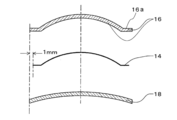
- the cut polarizing film has a flange portion.
- the upper mold 16 has a planar flange 16a on the lens flange.
- the flange portion is formed so as to easily hold the polarizing film in the upper mold.
- the flange portion is not essential, and the polarizing film can be held without the flange portion.
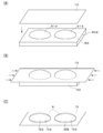
- FIG. 5 is a diagram for explaining a comparison of the shapes of the upper mold 16, the polarizing film, and the lower mold 18.
- the diameter (inner diameter) of the polarizing film 14 is about 2 mm smaller than the inner diameters of the upper mold 16 and the lower mold 18.
- FIG. 6A and 6B are views showing a state in which a holding member 20 made of an adhesive for holding the polarizing film is formed on the upper mold 16, FIG. 6A is a plan view, and FIG. FIG.
- holding members 20a, 20b, 20c, and 20d for holding the polarizing film are arranged at four positions at intervals of 90 ° on the flange portion 16a on the inner surface of the upper mold 16.
- the holding member is an adhesive, and the adhesive is pillar-shaped (adhesive pillar) so as to form a certain height.
- the holding members 20a, 20b, 20c, and 20d are for bonding and supporting the polarizing film. When the polarizing film is placed on these holding members, the polarizing film does not contact the inner surface of the upper mold 16.
- the height and position of the adhesive column are controlled so that the polarizing film can be held while maintaining a predetermined clearance (interval).
- reference numeral 300 denotes a lens shape of a spectacle frame that frames the polarizing lens, and the holding member 20 is cut after the frame processing.
- FIG. 7 is a view showing a method for applying an adhesive to the upper mold 16
- FIG. 8 is a view showing a discharge device 22 for applying the adhesive.
- an outline of the discharge device 22 for applying an adhesive will be described with reference to FIGS. 7 and 6.
- the discharge device 22 includes a main body 24 in which a motor device (not shown) is incorporated, a rotary shaft 26 that protrudes upward from the main body 24, and a turntable 28 that is disposed at the upper end of the rotary shaft 26.
- a motor device not shown
- a rotary shaft 26 that protrudes upward from the main body 24, and a turntable 28 that is disposed at the upper end of the rotary shaft 26.
- the reason for using the ring-shaped fixing pad 30 is to prevent the fixing means of the upper mold 16 from contacting the light transmitting surface of the outer surface portion 16b as much as possible.
- a syringe 36 is attached to a rod 32 extending upward from the main body 24 via a slider 34.
- the syringe 36 can discharge a viscous adhesive P from the needle 38 at the tip by a predetermined discharge amount by pneumatic control by a dispenser device in the main body 24 (not shown).
- the adhesive P it is preferable to use an ultraviolet curable resin (ultraviolet curable composition).
- the ultraviolet curable composition has a characteristic of chemically changing from a liquid to a solid in response to ultraviolet light energy.
- the composition containing ultraviolet curable components such as a prepolymer and a monomer, and a photoinitiator, and arbitrarily containing a well-known additive can be used.
- the type of the ultraviolet curable composition is not particularly limited, and it is preferable to select an appropriate one according to the type of the lens monomer.
- an ultraviolet curable epoxy resin can be illustrated by the point with the low reactivity with the various monomers used for manufacture of a plastic lens.
- an adhesive is applied to the upper mold 16.
- the upper mold 16 is placed on the fixed pad 30 of the turntable 28, the position of the syringe 36 is adjusted as appropriate, and the needle 38 is placed on the inner surface 16 a of the upper mold 16. Place it at a position facing the flange.
- the ejection device 22 is driven. That is, the turntable 28 is rotated to rotate the upper mold 16 in the circumferential direction, and when the lower part of the needle 38 reaches the pre-positioned position of the upper mold 16, the dispenser device is driven to drive the tip of the needle 38.
- the adhesive is discharged to the flange of the inner surface portion 16a.
- the adhesive installation location (adhesion position) is the peripheral portion of the inner surface of the upper mold or the surface of the polarizing film, and is usually a region that is cut when the lens is framed into the spectacle frame. Therefore, when it is molded into a lens, it is preferably closer to the outer peripheral end of the lens peripheral edge, and more preferably within 5 mm.
- the number of supporting points is set to 2 points or more, preferably 4 points or more depending on a predetermined interval at the facing position.
- the adhesive agent of each installation location shall be the same quantity, and height shall be made the same.
- ⁇ Adhesive height is formed at almost the same height at the bonding position by controlling the discharge amount of the adhesive.
- the height of the adhesive at each location is preferably the same.
- the height of the adhesive 20 is adjusted based on a predetermined interval between the polarizing film 14 and the upper mold 16.
- adjustment may be made in consideration of factors such as the shrinkage allowance of the adhesive, the manufacturing error of the mold and the polarizing film, and the width of the adhesive surface.
- the height of the adhesive is set to be slightly higher than the clearance, and the polarizing film can be brought into contact with the polarizing film so that the adhesive pillars are slightly crushed for adhesion.
- FIG. 9 and 10 are diagrams for explaining assembly of the mold.
- the upper mold 16 is brought close to the convex portion of the polarizing film 14 and polarized until it reaches a predetermined distance (distance equal to or less than the height of the holding member 20).
- the holding member 20 is placed horizontally on the film 14 and brought into contact therewith.
- the holding member 20 is irradiated with ultraviolet rays from the ultraviolet irradiation device 40 to solidify the holding member 20.
- the polarizing film 14 and the upper mold 16 are bonded, and the upper mold structure 16c in which the polarizing film 14 is held on the upper mold 16 is formed.
- the following method was implemented in order to improve the precision of the clearance between the upper mold 16 and the polarizing film.
- the center height of the inner surface side (concave surface side) of the upper mold 16 to be used and the center height of the polarizing film 14 to which the curved surface processing to be used is applied are measured.
- the horizontal surface on the lower surface side of the polarizing film 14 is measured using a non-contact type sensor (for example, a CCD transmission type digital laser sensor IG series manufactured by Keyence Corporation). Measure the height from the reference position to the top of the sphere.
- a contact type measurement probe for example, Mitutoyo Digimatic Indicator 543 series
- Mitutoyo Digimatic Indicator 543 series is used to move from the same reference position as the polarizing film.
- the height of the apex of the spherical upper mold 16 is measured.
- the upper mold 16 is moved in parallel from above, and the polarizing film 14 is brought into contact with the adhesive column that is the holding member 20 to be bonded and supported.
- the ultraviolet irradiation device 40 is driven to irradiate the adhesive 20 with ultraviolet rays from the tip of the irradiation lamp 44 to solidify the adhesive 20.
- the curing treatment of the ultraviolet curable composition usually requires only a short time (several seconds to several tens of seconds) of ultraviolet irradiation, so that the influence on the production cycle can be suppressed.
- ultraviolet rays are irradiated at 500 mW for 15 seconds. If it is determined that the amount of ultraviolet irradiation is insufficient, the turntable 28 can be rotated as appropriate, and ultraviolet irradiation by the ultraviolet irradiation device 40 can be continuously performed on the formed holding member 20.
- the shrinkage or expansion of the monomer due to heating / curing described later is negligible. In that case, it is not necessary to consider the shrinkage and expansion of the monomer in setting the clearance H.
- some lens monomers may shrink or expand due to heating / curing or the like, which will be described later. Therefore, when such lens monomers are used, the clearance H value should be taken into account the monomer shrinkage and expansion. May be set. As described above, the upper mold component 16c holding the polarizing film on the upper mold 16 is assembled.
- the polarizing film 14 should be formed (curved surface processing or cut) in consideration of the change in the shape of the polarizing film 14.
- a mold 48 the state of the upper mold 16 and the lower mold 18 and the adhesive tape 46 assembled with the polarizing film 14 interposed therebetween is referred to as a mold 48.
- Assembling of the mold using the tape of the upper mold 16 constituting body and the lower mold 18 is as described above, and for example, refer to JP-A-2001-330806.
- the upper mold 16 is brought close to the convex surface of the polarizing film 14 (the surface facing the upper mold 16). .
- the polarizing film 14 held on the fixing base 51 is brought close to the upper mold 16 held on the fixing pad 52.
- the holding member 20 is brought into contact with the polarizing film 14 by bringing the inner surface portion 16a of the upper mold 16 and the polarizing film 14 closer to a predetermined distance (a distance equal to or less than the height of the adhesive 20).
- Reference numeral 18 a denotes an inner surface portion of the lower mold 18.
- the ultraviolet irradiation device 40 is driven to irradiate the holding member 20 with ultraviolet rays from the tip of the irradiation lamp 44 to solidify the adhesive 20.
- the polarizing film 14 and the upper mold 16 are bonded, and the arrangement of the polarizing film 14 on the upper mold 16 is completed.
- the lower mold 18 is arranged to face the concave surface side of the polarizing film 14 so that the distance between the upper mold 16 and the lower mold 18 forms a predetermined cavity.
- material characteristics such as polymerization shrinkage of the lens monomer are taken into consideration, and as a result, a predetermined lens thickness based on the lens design is set to be satisfied. Then, as shown in FIG.
- the upper mold 16 and the lower mold 18 are held on a side surface of the upper mold 16 and the lower mold 18 while maintaining a predetermined distance.
- the adhesive tape 46 having a layer is wound around the entire circumference and slightly more than one round.
- the upper mold 16 and the lower mold 18 are set on the fixed pad 52.
- the fixed pad 52 is rotationally driven by a rotating shaft 54 protruding from a motor device (not shown).
- the material of the adhesive tape 46 does not react with the lens monomer to cause fogging of the lens or inhibit polymerization.
- a plastic adhesive tape For example, polypropylene and polyethylene terephthalate are used as the base material for the pressure-sensitive adhesive tape, and acrylic, natural rubber-based, and silicone-based materials are used in combination as the pressure-sensitive adhesive.
- the adhesive tape 46 may be provided with an injection hole (not shown) for injecting the monomer.
- the prepared lens monomer is injected into the assembled mold 48.
- the lens monomer will be described later.
- the monomer is filled into the cavity 50 formed by the upper mold 16 and the lower mold 18 and the adhesive tape 46 by using an injector from the injection hole so that no bubbles remain in the cavity 50.
- a monomer is injected between the upper mold 16 and the polarizing film 14 and between the lower mold 18 and the polarizing film 14.
- Monomers may be injected between the upper mold 16 and the polarizing film 14 (cavity 50a) and between the lower mold 18 and the polarizing film 14 (cavity 50b).
- the monomer can be circulated from one mold side to the other mold side.
- the lens monomer is not particularly limited, and various monomers usually used for the production of plastic lenses can be used. For example, those having a benzene ring, a naphthalene ring, an ester bond, a carbonate bond, or a urethane bond in the molecule can be used.
- a compound containing sulfur or a halogen element can also be used, and a compound having a nuclear halogen-substituted aromatic ring can also be used, and is particularly suitable for a compound having a nuclear halogen-substituted aromatic ring.
- a lens monomer can be produced by using one or more monomers having the functional group.
- styrene divinylbenzene, phenyl (meth) acrylate, benzyl (meth) acrylate, naphthyl (meth) acrylate, methyl (meth) acrylate, diethylene glycol bisallyl carbonate, diallyl (iso) phthalate, dibenzyl itaconate, dibenzyl fuma Rate, chlorostyrene, nuclear halogen substituted styrene, nuclear halogen substituted phenyl (meth) acrylate, nuclear halogen substituted benzyl (meth) acrylate, tetrabromobisphenol A derivative (di) (meth) acrylate, tetrabromobisphenol A derivative diallyl carbonate , Diortrochlorobenzyl itaconate, diortochlorobenzyl fumarate, diethylene glycol bis (ortrochlorobenzyl) fumarate, (di) ethylene Reaction products of poly
- the polarizing lens according to one embodiment of the present invention has a refractive index of, for example, 1.50 or more, and preferably a refractive index of 1.60 or more.
- the refractive index is, for example, 1.74 or less.
- the refractive index in the present invention refers to the refractive index nD.
- 1.60 thiourethane resin and thioepoxy resin are preferable in order to obtain a polarizing lens for spectacles having a lens thickness equivalent to that of a normal spectacle lens not including a polarizing film therein.
- a lens having a thin lens thickness with good aesthetics it is preferably made of a transparent plastic made of a high refractive index lens material and having a refractive index of 1.60 or more. In that case, it is preferable to prepare the following monomer.
- 4,8-dimercaptomethyl-1,11-dimercapto-3,6,9-trithiaundecane 4,7-dimercaptomethyl-1,11-dimercapto-3,6,9-tri Thiaundecane or 5,7-dimercaptomethyl-1,11-dimercapto-3,6,9-trithiaundecane may be used.
- 1.2 g of the trade name “SEESORB701” (manufactured by Sipro Kasei Kogyo Co., Ltd.) is added as an ultraviolet absorber
- 0.1 g of the trade name “internal mold release agent for MR” (manufactured by Mitsui Chemicals) is added as an internal mold release agent.
- dibutyltin dichloride as a catalyst is added to a plastic lens raw material that is thoroughly stirred and dispersed or dissolved, and stirred thoroughly at room temperature to obtain a uniform liquid.
- the composition is adjusted to 5 mmHg. Deaerate for 30 minutes while stirring under reduced pressure.
- Mercaptomethyl-1,11-dimercapto-3,6,9-trithiaundecane or 5,7-dimercaptomethyl-1,11-dimercapto-3,6,9-trithiaundecane may be used.
- 1.2 g of a trade name “SEESORB701” (manufactured by Sipro Kasei Kogyo Co., Ltd.) was added as an ultraviolet absorber, and the mixture was sufficiently stirred to be completely dissolved. Thereafter, 0.10 g of N, N-dimethylcyclohexylamine as a catalyst is mixed and sufficiently stirred at room temperature to obtain a uniform liquid. The composition is degassed for 30 minutes while stirring under reduced pressure to 5 mmHg.
- thermosetting lens monomer can be cured by placing the mold 48 filled with the lens monomer in a heating furnace and heating it.
- the heating conditions can be determined according to the type of the lens monomer, preferably 0 to 150 ° C., more preferably 10 to 130 ° C., preferably 5 to 50 hours, more preferably 10 to 25 hours.
- the temperature is raised and polymerization curing is performed. For example, the temperature is maintained at 30 ° C. for 7 hours, and then the temperature is raised from 30 to 120 ° C. over 10 hours.
- the monomer When the heat treatment is completed, the monomer is solidified and a lens in which the polarizing film 14 is embedded in the mold 48 is molded.
- the mold 48 is taken out from the heating furnace, the adhesive tape 46 is peeled off, and the lens is released from the upper mold 16 and the lower mold 18 to obtain the lens 100 shown in FIG.
- the concave surface 121 of the lens 100 is ground / polished by a curve generator and a polishing device to obtain a spectacle lens for correcting vision that matches the prescription power. it can.
- the processed spectacle lens is further subjected to surface treatment such as primer, hard coat, antireflection film, water repellent treatment, etc. for the purpose of impact resistance, abrasion resistance, antireflection, water repellent treatment, etc. Done.
- surface treatment such as primer, hard coat, antireflection film, water repellent treatment, etc. for the purpose of impact resistance, abrasion resistance, antireflection, water repellent treatment, etc. Done.
- the hard coat layer can impart scratch resistance to the plastic lens. Also, since the adhesion of the antireflection layer to the plastic lens is generally not good, the hard coat functions to prevent peeling by interposing between the plastic lens and the antireflection layer to improve the adhesion of the antireflection layer.
- the layer can also take on.
- a method for forming the hard coat layer a method of applying a curable composition to the surface of a plastic lens and curing the coating film is common.
- the curing process is performed by heating, light irradiation, or the like depending on the type of the curable composition.
- a cured film can be formed by applying a thermosetting composition on a polarized lens after release and then heating.
- the plastic lens is a thermoplastic resin
- a material that is cured by an electromagnetic wave such as ultraviolet rays or ionizing radiation such as an electron beam is preferably used rather than a thermosetting type.
- a silicone compound that generates a silanol group by ultraviolet irradiation and an organopolysiloxane having a reactive group such as a halogen atom or an amino group that undergo a condensation reaction with the silanol group are the main components.
- Photo-curable silicone composition acrylic UV-curable monomer composition such as UK-6074 manufactured by Mitsubishi Rayon Co., Ltd .; inorganic fine particles such as SiO 2 and TiO 2 having a particle diameter of 1 nm to 100 nm, vinyl group, allyl
- inorganic fine particle-containing thermosetting compositions dispersed in a silane compound having a polymerizable group such as a group, an acrylic group or a methacryl group and a hydrolyzable group such as a methoxy group, or a silane coupling agent.
- a method for forming a coating film As a method for forming a coating film, a dipping method, a spin coating method, a spray method, a flow method, a doctor blade method and the like can be adopted. For example, by heating and drying at a temperature of 40 to 200 ° C. for several minutes to several hours. A film is formed. Moreover, before forming a coating film, in order to improve adhesiveness, it is preferable to surface-treat the lens surface by high voltage discharge such as corona discharge or microwave. Thereafter, the formed coating film can be cured by heat, ultraviolet light, electron beam or the like to form a hard coat layer.
- the antireflection layer is composed of a single layer or multiple layers of an inorganic coating or an organic coating.
- the material of the inorganic film SiO 2, SiO, ZrO 2 , TiO 2, TiO, Ti 2 O 3, Ti 2 O 5, Al 2 O 3, Ta 2 O 5, CeO 2, MgO, Y 2 O 3, Examples include inorganic substances such as SnO 2 , MgF 2 , and WO 3 , and these can be used alone or in combination of two or more.
- SiO 2 , ZrO 2 , TiO 2 , and Ta 2 O 5 that can be vacuum-deposited at a low temperature are preferable.
- the outermost layer is preferably made of SiO 2 .
- outermost layer forming the antifouling film according to the present invention on the surface of the antireflection layer is SiO 2, it is possible to further improve the durability of the antifouling film in the obtained optical article.
- the multi-layer film of an inorganic film for example, ZrO 2 layer and the SiO 2 layer of the total optical film thickness of lambda / 4, ZrO 2 layers of optical thickness is lambda / 2, and the optical film A four-layer structure in which SiO 2 layers having a thickness of ⁇ / 4 are sequentially laminated from the lens side can be exemplified.
- ⁇ is a design wavelength, and usually 520 nm is used.
- a method for forming the inorganic film for example, a vacuum deposition method, an ion plating method, a sputtering method, a CVD method, a method of depositing by a chemical reaction in a saturated solution, or the like can be employed.
- a polarizing lens in which a polarizing film is embedded in the lens, and the surface of the lens, preferably the surface on the object side, is less deformed.
- the difference (Rmax ⁇ Rmin) between the maximum curvature radius Rmax and the minimum curvature radius Rmin at the geometric center position of the object-side surface is less than 4 mm.
- the minimum distance between the object-side surface and the polarizing lens is 0.7 mm or less, the polarizing film is relatively close to the object-side surface, and the object-side surface is easily deformed due to the influence of deformation of the polarizing film.
- (Rmax ⁇ Rmin) can be realized to be less than 4 mm.
- the object side surface is used.
- Astigmatism AS ⁇ 0.17 can be realized if (Rmax ⁇ Rmin) is less than 4 mm in a lens having a base curve of about 5.25D or less.
- the minimum value of the distance between the object-side surface and the polarizing film is 0.7 mm or less, Even when the polarizing film is relatively close to the object-side surface and the object-side surface is easily deformed due to the deformation of the polarizing film, the deformation can be prevented.
- Example 1 Wet treatment of polarizing film, curved surface processing, and subsequent heat treatment A commercially available PVA-made two-color dye-based polarizing film 14 is placed in a constant humidity and high temperature apparatus and wet treated, and the water content at the start of curved surface processing is about 4%. It was made to become so that it might become.
- the wet polarizing film was allowed to stand at room temperature (20 to 25 ° C.) for about 2 minutes, and then subjected to curved surface processing by the method described above based on FIG. Curved surface processing was similarly performed at room temperature. Next, the curved polarizing film was heated at 120 ° C. for 30 minutes using a commercially available circulating hot air oven. The heating was performed without using the glass mold 60.
- the above-described method described with reference to FIGS. 6 to 8 was used to prepare an upper mold structure by providing adhesive columns at four locations on the inner peripheral surface of the upper mold. Thereafter, the mold 48 was assembled with the upper mold 16, the lower mold 18, and the adhesive tape 46 with the polarizing film 14 interposed therebetween by the method described above based on FIG. 9.
- the upper mold 16 and the lower mold 18 have a spherical surface, an inner diameter of 80 mm, and a curvature radius of 130.4 mm.
- the mold 48 is taken out from the heating furnace, the adhesive tape 46 is peeled off, and the lens is released from the upper mold 16 and the lower mold 18 to obtain the lens 100 (semi-finish lens) shown in FIG. It was.
- the obtained lens has a refractive index nD of 1.67.
- the concave surface 121 of the obtained lens 100 was ground / polished by a curve generator and a polishing apparatus to obtain an eyesight correcting eyeglass lens matching the prescription power.
- a coating solution (coating solution) for forming the hard coat layer was prepared as follows. (1) Preparation of coating liquid After mixing 500 g of perfluorohexane and 350 g of IPA-dispersed silicon oxide sol (solid content concentration: 30 wt%, Oscar 1432 manufactured by Catalyst Chemical Industries, Ltd.), fluoroalkylsilane (GE Toshiba Silicone Co., Ltd.) Manufactured by TSL8233), 220 g of ⁇ -glycidoxypropyltrimethoxysilane, and 25 g of tetraethoxysilane were mixed.
- the vapor deposition apparatus is an electron beam vapor deposition apparatus, and includes a vacuum vessel, an exhaust device, and a gas supply device.
- the vacuum vessel generates a lens support on which a lens on which a hard coat layer is formed (film formation) is placed, a substrate heating heater for heating the lens set on the lens support, and thermoelectrons And a filament to be used.
- the vapor deposition material set in the evaporation source (crucible) by the electron gun is irradiated with thermionic electrons and evaporated to deposit the material on the lens.
- Optical film thickness of each layer, the first SiO 2 layer, the equivalent layer and the next ZrO 2 layer of the next ZrO 2 and SiO 2 was formed as a lambda / 4, respectively.
- the design wavelength ⁇ was 520 nm.
- the difference in curvature (Rmax ⁇ Rmin) between the maximum radius of curvature (mm) and the minimum radius of curvature (mm) was used as an index of lens deformation (astigmatism) and evaluated as follows.
- the convex surface of the lens 100 has a spherical design, and the convex geometric center is the intersection of a perpendicular passing through the center of the circle when the lens 100 is viewed in plan view and the lens convex surface side 111.
- Curvature difference is 0 or more and less than 3 mm: ⁇ (passed), 3 mm or more and less than 4 mm: ⁇ (Slightly deformed, but no problem for wearing glasses, 4 mm or more: ⁇ (practical, troubled)
- Examples 2 to 5 and Comparative Examples 1 to 4> A lens 100 was produced in the same manner as in Example 1 except that the curved film processed polarizing film 14 was heated under the conditions shown in Table 1. In Comparative Example 1, the polarizing film was used without heating.
- Example 1 instead of the commercially available PVA dichroic dye polarizing film 14, a commercially available polarizing film (TPT) having a TAC protective film on both sides of the PVA dichroic dye polarizing film was used.
- TPT polarizing film
- a lens 100 was produced in the same manner as in Example 1 except that the polarizing film was heated under the conditions.
- Example 8> A lens 100 was produced in the same manner as in Example 2 except that the polarizing film 14 was held and heated on the curved surface processing table 60 used for the curved surface processing.
- Example 4 in which the curved film processed polarizing film 14 was heated at 105 ° C., the difference in curvature radius (Rmax ⁇ Rmin) was 3.5 mm. Further, in Examples 5 and 7 in which the polarizing film 14 was heated at 140 ° C., discoloration to such an extent that the hue did not change was observed, but the lenses obtained in any of the examples were practically satisfactory as a polarizing lens. It was usable. It was also found that heating at 120 ° C. to 130 ° C. yields a lens 100 with less optical deformation and better appearance, with less deformation of the lens and discoloration of the polarizing film 14.
- the shape of the lens was not limited to the PVA film, but the polarizing film heated under the same conditions was used for other films. It was found that deformation can be suppressed. Since the PVA film is inexpensive, the lens 100 can be provided at a lower cost by using the PVA film.
- Comparative Examples 1 to 3 and Comparative Example 5 the difference in radius of curvature (Rmax ⁇ Rmin) is 4 mm or more, and the lens is greatly deformed.
- the heating temperature was less than 105 ° C., and it is considered that the polarizing film did not sufficiently shrink before injection of the polymerizable composition for the lens substrate. Thereby, it is considered that the polarizing film contracted during the heat curing, and the lens was deformed.
- Comparative Example 4 and Comparative Example 6 since the polarizing film was heated at 150 ° C., deformation of the lens could be suppressed, but the polarizing film was altered and discoloration occurred.
- Example 1 to 7 in which the curved surface processing table 60 was not used, a slight distortion occurred in the shape of the polarizing film 14, whereas in Example 8 in which the curved surface processing table 60 was used, distortion was suppressed and superior optical performance was achieved. A lens 100 having performance was obtained. Therefore, it was found that by holding and heating the polarizing film 14 on the curved processing table 60, the shape deformation and distortion of the polarizing film 14 can be suitably suppressed, and the lens 100 with better appearance can be obtained.
- the present invention it is possible to provide a polarizing lens with less deformation of the lens surface shape that causes astigmatism.
- the minimum distance between the object side surface of the polarizing lens obtained in the above example and the polarizing film is 0.3 mm or more and 0.7 mm or less, and the polarizing film is disposed at a position relatively close to the object side surface. ing.
- deformation of the object-side surface can be suppressed.
- the curved film member 10 is held and heated by the curved surface processing table 60 used for the curved surface processing, it is possible to suppress the shape of the curved surface portion 61a of the film member 10 from changing from the set shape. Therefore, the lens 100 with a better appearance can be manufactured.
- a PVA polarizing film which is common as the polarizing film 14, was used. Since the PVA film is inexpensive, the lens 100 with less aberration can be provided at a lower cost.
- H is the minimum distance between the inner surface of the upper mold and the polarizing film in the mold (hereinafter simply referred to as clearance H)
- W1 is the object-side surface of the plastic lens (semi-finished lens).
- the minimum value of the distance between the polarizing film and the polarizing film (hereinafter simply referred to as the distance W1). This is the minimum lens thickness (hereinafter simply referred to as thickness W) obtained later.
- SF is an abbreviation for semi-finished lens.
- the base curve of the lens is the base curve of the object side surface.
- the position where the clearance is minimized is the center of the semi-finished lens (the position of the apex T) when the base curve is less than 6D, and the outer periphery of the semi-finished lens when the base curve is 6D or more.
- the clearance H was set at this position for the samples.
- the position where the distance between the eyeball side surface and the polarizing film was minimized was the same position as the position where the clearance H was set.
- Ten lenses were prepared for each sample. In some samples, the curvature of the polarizing film is changed according to the base curve of the lens. However, it is also possible to use a polarizing film having the same curvature in all the samples.
- Sample 1-5 is an example using a TPT film as a polarizing film
- Sample 1-6 is an example using a PET film as a polarizing film.
- 1.60 thiourethane indicates that the lens substrate is a thiourethane lens having a refractive index of 1.60
- 1.67 thiourethane indicates that the lens substrate is refracted. This indicates that the lens was a thiourethane lens having a refractive index of 1.67
- 1.74 thioepoxy indicates that the lens substrate was a thioepoxy lens having a refractive index of 1.74.
- Sample 2-5 is Sample 1-1, except that instead of adhering the polarizing film to the inner surface of the upper mold with an adhesive, the polarizing film was inserted and held in the insertion groove provided in the gasket.
- the lens obtained in the same manner as above.
- Samples 1-3 and 1-4 in which the lens substrate is changed Samples 1-5 and 1-6 in which the material of the polarizing film is changed, and Samples 1-7 to 1- 12 in which the lens base curve is changed.
- a finished lens having a thickness W of 1.1 mm was obtained.
- the plastic lens having the distance W1 of 0.3 mm (samples 1-2 and 1-8) is removed by surface processing until the thickness W becomes about 0.6 mm to 0.7 mm, but the thickness W If the thickness is less than 1.1 mm, the strength of the finished product lens may be insufficient, so the surface processing is finished at 1.1 mm.
- the clearance H was set to 0.2 mm, so that the monomer can flow uniformly between the first mold and the polarizing film in the monomer injection step. could not.
- the clearance H is 0.8 mm, the finished product lens thickness W1 is 1.2 mm due to the processing limit of the prescription surface, and a normal polarizing film is not included. Thicker than eyeglass lenses.
- the plastic lens was manufactured using a gasket, so the curved surface accuracy of the polarizing film varied, and the distance W1 varied from 0.5 mm to 1.2 mm among the 10 plastic lenses manufactured. Occurred.
- the surface processing cannot be performed until the thickness W becomes 0.3 mm to 0.4 mm, and the thickness W of the finished product lens is 1.6 mm. It was thicker than a normal spectacle lens that did not contain a polarizing film inside.
- the mold it is preferable to assemble the mold with a tape and an adhesive so that the minimum distance between the object-side surface and the polarizing film is 0.3 mm to 0.7 mm. It can be confirmed that a semi-finished lens in which a polarizing film is embedded and a polarizing lens capable of providing a thin spectacle lens by surface processing of the eyeball side surface can be confirmed.
- the base curve of the lens (base curve of the refractive surface on the convex surface side) is 4 (D), the curvature of the polarizing film is 3 (D), and the curvature of the polarizing film is 1 (D ) Shallow.
- the distance between the lens apex and the position of the polarizing film corresponding to the lens apex is set to 0.7 mm, the lens concave surface is cut and polished after the lens molding, and the lens thickness at the center of the lens is 1.1 mm.
- the base curve of the lens is 2 (D)
- the curvature of the polarizing film is 3 (D)
- the curvature of the polarizing film is 1 (D) deeper.
- the distance between the lens apex and the position of the polarizing film corresponding to the lens apex is set to 0.7 mm, and after lens molding, the concave surface of the lens is cut and polished, and the lens thickness at the center of the lens is 1.1 mm. ing.
- the base curve of the lens is 6 (D)
- the curvature of the polarizing film is 4 (D)
- the curvature of the polarizing film is 2 (D) shallower.
- the distance between the lens apex and the position of the polarizing film corresponding to the lens apex is set to 0.7 mm, and after lens molding, the concave surface of the lens is cut and polished, and the lens thickness at the peripheral edge of the lens is 1.1 mm.
- the base curve of the lens is 8 (D)
- the curvature of the polarizing film is 6 (D)
- the curvature of the polarizing film is 2 (D) shallower.
- the base curve of the lens is 10 (D)
- the curvature of the polarizing film is 8 (D)
- the curvature of the polarizing film is 2 (D) shallower.
- the upper mold inner surface and the polarizing film As shown in Table 2, by using a high refractive lens substrate having a refractive index of 1.60 or more, and setting the difference between the polarizing film and the lens convex curve within 2D, the upper mold inner surface and the polarizing film The minimum value of the distance can be easily set to 0.3 mm or more and 0.7 mm or less, and the surface of the eyeball side of the semi-finished lens thus obtained is subjected to surface processing so that the minimum lens thickness is 1.1 mm. Lens can be obtained.
- the present invention is useful in the field of manufacturing eyeglass lenses.
Priority Applications (5)
| Application Number | Priority Date | Filing Date | Title |
|---|---|---|---|
| JP2014506648A JP6316184B2 (ja) | 2012-08-02 | 2013-08-02 | 偏光レンズの製造方法 |
| MX2014005364A MX362399B (es) | 2012-08-02 | 2013-08-02 | Lentes polarizantes y metodo para su produccion. |
| US14/355,944 US9638938B2 (en) | 2012-08-02 | 2013-08-02 | Polarizing lens and method of manufacturing the same |
| CN201380003319.3A CN103930808B (zh) | 2012-08-02 | 2013-08-02 | 偏光透镜及其制造方法 |
| EP13825675.5A EP2796907B1 (en) | 2012-08-02 | 2013-08-02 | Polarizing lens and method for producing same |
Applications Claiming Priority (2)
| Application Number | Priority Date | Filing Date | Title |
|---|---|---|---|
| JP2012-172255 | 2012-08-02 | ||
| JP2012172255 | 2012-08-02 |
Publications (1)
| Publication Number | Publication Date |
|---|---|
| WO2014021466A1 true WO2014021466A1 (ja) | 2014-02-06 |
Family
ID=50028129
Family Applications (1)
| Application Number | Title | Priority Date | Filing Date |
|---|---|---|---|
| PCT/JP2013/071077 WO2014021466A1 (ja) | 2012-08-02 | 2013-08-02 | 偏光レンズおよびその製造方法 |
Country Status (6)
| Country | Link |
|---|---|
| US (1) | US9638938B2 (es) |
| EP (1) | EP2796907B1 (es) |
| JP (1) | JP6316184B2 (es) |
| CN (1) | CN103930808B (es) |
| MX (1) | MX362399B (es) |
| WO (1) | WO2014021466A1 (es) |
Cited By (10)
| Publication number | Priority date | Publication date | Assignee | Title |
|---|---|---|---|---|
| CH709485A1 (de) * | 2014-04-11 | 2015-10-15 | Interglass Technology Ag | Verfahren zum Herstellen einer Linse durch Giessen. |
| WO2016021679A1 (ja) * | 2014-08-07 | 2016-02-11 | 三井化学株式会社 | プラスチック偏光レンズおよびその製造方法 |
| KR20160128922A (ko) * | 2015-04-29 | 2016-11-08 | 주식회사 트리아펙스 | 편광 필름, 이의 제조 방법, 및 이를 포함하는 편광 렌즈 |
| JP2018506067A (ja) * | 2015-01-14 | 2018-03-01 | コベストロ、ドイチュラント、アクチエンゲゼルシャフトCovestro Deutschland Ag | ホログラフィック光学素子を有する光学鋳造体の製造方法および光学鋳造体 |
| WO2019230884A1 (ja) | 2018-05-31 | 2019-12-05 | ホヤ レンズ タイランド リミテッド | 偏光フィルム、偏光フィルムの成型方法および偏光レンズの製造方法 |
| JP2019536087A (ja) * | 2016-11-03 | 2019-12-12 | インターグラス テクノロジー アーゲー | 箔が埋め込まれたレンズを製造する方法 |
| WO2020203382A1 (ja) | 2019-03-29 | 2020-10-08 | ホヤ レンズ タイランド リミテッド | 偏光付きレンズ及びその製造方法 |
| JPWO2020262400A1 (es) * | 2019-06-28 | 2020-12-30 | ||
| JPWO2020262402A1 (es) * | 2019-06-28 | 2020-12-30 | ||
| WO2020262399A1 (ja) * | 2019-06-28 | 2020-12-30 | ホヤ レンズ タイランド リミテッド | 偏光レンズの製造方法、偏光フィルム及び偏光レンズ |
Families Citing this family (15)
| Publication number | Priority date | Publication date | Assignee | Title |
|---|---|---|---|---|
| DE102013222232B4 (de) * | 2013-10-31 | 2021-01-28 | Carl Zeiss Vision International Gmbh | Herstellungsverfahren für ein Brillenglas |
| JP5873584B1 (ja) * | 2015-03-12 | 2016-03-01 | 株式会社ホプニック研究所 | プラスチックレンズの製造方法、フィルムの位置決め方法 |
| KR101625484B1 (ko) * | 2015-05-18 | 2016-05-30 | 조정애 | 편광렌즈의 제조방법 및 이에 의해 제조된 편광렌즈 |
| CA2996721A1 (en) * | 2015-09-04 | 2017-03-09 | Thalmic Labs Inc. | Systems, articles, and methods for integrating holographic optical elements with eyeglass lenses |
| CN105388634A (zh) * | 2015-12-21 | 2016-03-09 | 瑞安市圣视光学有限公司 | 一种偏光镜片 |
| CN106094094B (zh) * | 2016-08-24 | 2019-07-23 | 京东方科技集团股份有限公司 | 偏光片、显示面板、曲面显示面板及制备方法、显示装置 |
| JP6877211B2 (ja) * | 2017-03-30 | 2021-05-26 | デクセリアルズ株式会社 | 光学装置の製造方法及び光学装置 |
| JP6664347B2 (ja) * | 2017-03-31 | 2020-03-13 | 富士フイルム株式会社 | レンズの製造方法 |
| JP2019056786A (ja) * | 2017-09-21 | 2019-04-11 | 日本電産サンキョー株式会社 | レンズユニット |
| KR102246299B1 (ko) * | 2019-03-12 | 2021-04-29 | 주식회사 온빛 | 고굴절 편광렌즈의 제조방법 |
| EP3871865A1 (en) * | 2019-04-11 | 2021-09-01 | Interglass Technology AG | Method of manufacturing a lens with an embedded foil |
| CN110000977B (zh) * | 2019-04-18 | 2023-10-13 | 浙江盘毂动力科技有限公司 | 一种电机铁芯覆层的制作装置和制作方法 |
| US20220274299A1 (en) * | 2019-07-30 | 2022-09-01 | Magic Leap, Inc. | Angularly segmented hot mirror for eye tracking |
| US20230390972A1 (en) * | 2021-01-21 | 2023-12-07 | Tobii Ab | Improvements relating to lenses |
| JP2022136683A (ja) * | 2021-03-08 | 2022-09-21 | ホヤ レンズ タイランド リミテッド | 眼鏡用偏光レンズ、眼鏡用偏光レンズの製造方法、フレーム付き眼鏡の製造方法、および、眼鏡用偏光レンズの検査方法 |
Citations (7)
| Publication number | Priority date | Publication date | Assignee | Title |
|---|---|---|---|---|
| JP2001330806A (ja) | 2000-03-17 | 2001-11-30 | Topcon Corp | 眼鏡フレーム合成システム及び眼鏡フレーム販売方法 |
| JP2007052210A (ja) * | 2005-08-17 | 2007-03-01 | Nikon-Essilor Co Ltd | 偏光レンズとその製造方法 |
| US20070098999A1 (en) | 2004-01-30 | 2007-05-03 | Essilor Inernational Compagnie Generale 'optique | Polarized articles and methods for obtaining polarized articles |
| JP2007168310A (ja) * | 2005-12-22 | 2007-07-05 | Ito Kogaku Kogyo Kk | 偏光プラスチックレンズの成形型及び成形方法 |
| JP2007316595A (ja) | 2006-04-27 | 2007-12-06 | Seiko Epson Corp | プラスチック偏光レンズ |
| WO2009098886A1 (ja) * | 2008-02-07 | 2009-08-13 | Mitsui Chemicals, Inc. | プラスチック偏光レンズ及びその製造方法 |
| JP2011145513A (ja) * | 2010-01-15 | 2011-07-28 | Ito Kogaku Kogyo Kk | 偏光素子 |
Family Cites Families (7)
| Publication number | Priority date | Publication date | Assignee | Title |
|---|---|---|---|---|
| JP4455743B2 (ja) * | 2000-09-12 | 2010-04-21 | 山本光学株式会社 | 偏光レンズの製造方法 |
| JP2002267841A (ja) | 2001-03-09 | 2002-09-18 | Mitsui Chemicals Inc | 偏光レンズ用偏光フィルム |
| WO2004099859A1 (ja) * | 2003-05-12 | 2004-11-18 | Hopnic Laboratory Co., Ltd. | 高屈折率偏光レンズの製造方法 |
| US20060023160A1 (en) * | 2004-08-02 | 2006-02-02 | Cartier Jon P | Lens structure and method of making the same |
| WO2009054835A1 (en) * | 2007-10-25 | 2009-04-30 | Eye Ojo Corp. | Polarized lens and method of making polarized lens |
| JP2011033831A (ja) | 2009-07-31 | 2011-02-17 | Hoya Corp | 偏光レンズの製造方法 |
| US20130208239A1 (en) * | 2012-02-15 | 2013-08-15 | Peiqi Jiang | Process for manufacturing a polarized optical article and polarized optical article |
-
2013
- 2013-08-02 EP EP13825675.5A patent/EP2796907B1/en active Active
- 2013-08-02 WO PCT/JP2013/071077 patent/WO2014021466A1/ja active Application Filing
- 2013-08-02 MX MX2014005364A patent/MX362399B/es active IP Right Grant
- 2013-08-02 CN CN201380003319.3A patent/CN103930808B/zh active Active
- 2013-08-02 US US14/355,944 patent/US9638938B2/en active Active
- 2013-08-02 JP JP2014506648A patent/JP6316184B2/ja active Active
Patent Citations (10)
| Publication number | Priority date | Publication date | Assignee | Title |
|---|---|---|---|---|
| JP2001330806A (ja) | 2000-03-17 | 2001-11-30 | Topcon Corp | 眼鏡フレーム合成システム及び眼鏡フレーム販売方法 |
| US20070098999A1 (en) | 2004-01-30 | 2007-05-03 | Essilor Inernational Compagnie Generale 'optique | Polarized articles and methods for obtaining polarized articles |
| JP2007523768A (ja) | 2004-01-30 | 2007-08-23 | エシロール アテルナジオナール カンパニー ジェネラーレ デ オプティック | 偏光製品および偏光製品を得る方法 |
| US7767304B2 (en) | 2004-01-30 | 2010-08-03 | Essilor International Compagnie Generale D'optique | Polarized articles and methods for obtaining polarized articles |
| JP2007052210A (ja) * | 2005-08-17 | 2007-03-01 | Nikon-Essilor Co Ltd | 偏光レンズとその製造方法 |
| JP2007168310A (ja) * | 2005-12-22 | 2007-07-05 | Ito Kogaku Kogyo Kk | 偏光プラスチックレンズの成形型及び成形方法 |
| JP2007316595A (ja) | 2006-04-27 | 2007-12-06 | Seiko Epson Corp | プラスチック偏光レンズ |
| US20090091825A1 (en) | 2006-04-27 | 2009-04-09 | Seiko Epson Corporation | Plastic Polarized Lens |
| WO2009098886A1 (ja) * | 2008-02-07 | 2009-08-13 | Mitsui Chemicals, Inc. | プラスチック偏光レンズ及びその製造方法 |
| JP2011145513A (ja) * | 2010-01-15 | 2011-07-28 | Ito Kogaku Kogyo Kk | 偏光素子 |
Cited By (23)
| Publication number | Priority date | Publication date | Assignee | Title |
|---|---|---|---|---|
| CH709485A1 (de) * | 2014-04-11 | 2015-10-15 | Interglass Technology Ag | Verfahren zum Herstellen einer Linse durch Giessen. |
| WO2016021679A1 (ja) * | 2014-08-07 | 2016-02-11 | 三井化学株式会社 | プラスチック偏光レンズおよびその製造方法 |
| JPWO2016021679A1 (ja) * | 2014-08-07 | 2017-04-27 | 三井化学株式会社 | プラスチック偏光レンズおよびその製造方法 |
| US11000976B2 (en) | 2015-01-14 | 2021-05-11 | Covestro Deutschland Ag | Method for producing an optical cast body having a holographic optical element, and optical cast body |
| JP2018506067A (ja) * | 2015-01-14 | 2018-03-01 | コベストロ、ドイチュラント、アクチエンゲゼルシャフトCovestro Deutschland Ag | ホログラフィック光学素子を有する光学鋳造体の製造方法および光学鋳造体 |
| KR20160128922A (ko) * | 2015-04-29 | 2016-11-08 | 주식회사 트리아펙스 | 편광 필름, 이의 제조 방법, 및 이를 포함하는 편광 렌즈 |
| US10408982B2 (en) | 2015-04-29 | 2019-09-10 | Triaplex Co., Ltd. | Polarizing film, preparation method thereof, polarizing lens comprising the same |
| KR102052168B1 (ko) * | 2015-04-29 | 2019-12-04 | 주식회사 트리아펙스 | 편광 필름, 이의 제조 방법, 및 이를 포함하는 편광 렌즈 |
| JP2019536087A (ja) * | 2016-11-03 | 2019-12-12 | インターグラス テクノロジー アーゲー | 箔が埋め込まれたレンズを製造する方法 |
| US11813814B2 (en) | 2016-11-03 | 2023-11-14 | Interglass Technology Ag | Method of producing a lens with an embedded foil |
| US11529779B2 (en) | 2016-11-03 | 2022-12-20 | Interglass Technology Ag | Method of producing a lens with an embedded foil |
| JP7191016B2 (ja) | 2016-11-03 | 2022-12-16 | メタマテリアル インク | 箔が埋め込まれたレンズを製造する方法 |
| WO2019230884A1 (ja) | 2018-05-31 | 2019-12-05 | ホヤ レンズ タイランド リミテッド | 偏光フィルム、偏光フィルムの成型方法および偏光レンズの製造方法 |
| JP7210076B2 (ja) | 2018-05-31 | 2023-01-23 | ホヤ レンズ タイランド リミテッド | 偏光フィルム、偏光フィルムの成型方法および偏光レンズの製造方法 |
| JPWO2019230884A1 (ja) * | 2018-05-31 | 2021-09-09 | ホヤ レンズ タイランド リミテッドHOYA Lens Thailand Ltd | 偏光フィルム、偏光フィルムの成型方法および偏光レンズの製造方法 |
| WO2020203382A1 (ja) | 2019-03-29 | 2020-10-08 | ホヤ レンズ タイランド リミテッド | 偏光付きレンズ及びその製造方法 |
| JPWO2020262400A1 (es) * | 2019-06-28 | 2020-12-30 | ||
| WO2020262402A1 (ja) * | 2019-06-28 | 2020-12-30 | ホヤ レンズ タイランド リミテッド | 偏光レンズの製造方法、偏光フィルム及び偏光レンズ |
| JPWO2020262399A1 (es) * | 2019-06-28 | 2020-12-30 | ||
| WO2020262399A1 (ja) * | 2019-06-28 | 2020-12-30 | ホヤ レンズ タイランド リミテッド | 偏光レンズの製造方法、偏光フィルム及び偏光レンズ |
| JPWO2020262402A1 (es) * | 2019-06-28 | 2020-12-30 | ||
| JP7357051B2 (ja) | 2019-06-28 | 2023-10-05 | ホヤ レンズ タイランド リミテッド | 偏光レンズの製造方法、偏光フィルム及び偏光レンズ |
| WO2020262400A1 (ja) * | 2019-06-28 | 2020-12-30 | ホヤ レンズ タイランド リミテッド | 偏光レンズ |
Also Published As
| Publication number | Publication date |
|---|---|
| MX362399B (es) | 2019-01-16 |
| CN103930808A (zh) | 2014-07-16 |
| US9638938B2 (en) | 2017-05-02 |
| EP2796907B1 (en) | 2019-01-02 |
| MX2014005364A (es) | 2014-10-17 |
| EP2796907A4 (en) | 2015-10-07 |
| JP6316184B2 (ja) | 2018-04-25 |
| US20140293217A1 (en) | 2014-10-02 |
| CN103930808B (zh) | 2018-05-29 |
| EP2796907A1 (en) | 2014-10-29 |
| JPWO2014021466A1 (ja) | 2016-07-21 |
Similar Documents
| Publication | Publication Date | Title |
|---|---|---|
| JP6316184B2 (ja) | 偏光レンズの製造方法 | |
| JP6110595B2 (ja) | 眼鏡用偏光プラスチックレンズの製造方法 | |
| US10099439B2 (en) | Method of manufacturing polarizing plastic lens | |
| WO2010113996A1 (ja) | 偏光レンズの製造方法、偏光レンズ、およびレンズの製造方法 | |
| EP3809170B1 (en) | Method for molding polarizing film, and method for manufacturing polarizing lens | |
| EP2921900B1 (en) | Method for manufacturing polarizing plastic lens | |
| JP6207622B2 (ja) | アイウエア用偏光レンズの製造方法 | |
| US7128415B2 (en) | Method of forming polarized or photochromic lenses by fusing polycarbonate with other plastic materials | |
| TWI826419B (zh) | 鏡片及鏡片的製造方法 | |
| JP2014142440A (ja) | 偏光レンズの製造方法 | |
| EP1621326B1 (en) | Method of forming polarized or photochromic lenses by fusing polycarbonate with other plastic materials | |
| AU2004203010B2 (en) | Method of Forming Polarized or Photochromic Lenses by Fusing Polycarbonate with other Plastic Materials |
Legal Events
| Date | Code | Title | Description |
|---|---|---|---|
| ENP | Entry into the national phase |
Ref document number: 2014506648 Country of ref document: JP Kind code of ref document: A |
|
| 121 | Ep: the epo has been informed by wipo that ep was designated in this application |
Ref document number: 13825675 Country of ref document: EP Kind code of ref document: A1 |
|
| WWE | Wipo information: entry into national phase |
Ref document number: 14355944 Country of ref document: US Ref document number: MX/A/2014/005364 Country of ref document: MX |
|
| NENP | Non-entry into the national phase |
Ref country code: DE |