WO2014020861A1 - Fixing member, method for producing same, fixing device and image forming device - Google Patents
Fixing member, method for producing same, fixing device and image forming device Download PDFInfo
- Publication number
- WO2014020861A1 WO2014020861A1 PCT/JP2013/004481 JP2013004481W WO2014020861A1 WO 2014020861 A1 WO2014020861 A1 WO 2014020861A1 JP 2013004481 W JP2013004481 W JP 2013004481W WO 2014020861 A1 WO2014020861 A1 WO 2014020861A1
- Authority
- WO
- WIPO (PCT)
- Prior art keywords
- fixing member
- tetrafluoroethylene
- vinyl ether
- ether copolymer
- perfluoroalkyl vinyl
- Prior art date
Links
Images


Classifications
-
- G—PHYSICS
- G03—PHOTOGRAPHY; CINEMATOGRAPHY; ANALOGOUS TECHNIQUES USING WAVES OTHER THAN OPTICAL WAVES; ELECTROGRAPHY; HOLOGRAPHY
- G03G—ELECTROGRAPHY; ELECTROPHOTOGRAPHY; MAGNETOGRAPHY
- G03G15/00—Apparatus for electrographic processes using a charge pattern
- G03G15/20—Apparatus for electrographic processes using a charge pattern for fixing, e.g. by using heat
- G03G15/2003—Apparatus for electrographic processes using a charge pattern for fixing, e.g. by using heat using heat
- G03G15/2014—Apparatus for electrographic processes using a charge pattern for fixing, e.g. by using heat using heat using contact heat
- G03G15/2017—Structural details of the fixing unit in general, e.g. cooling means, heat shielding means
-
- G—PHYSICS
- G03—PHOTOGRAPHY; CINEMATOGRAPHY; ANALOGOUS TECHNIQUES USING WAVES OTHER THAN OPTICAL WAVES; ELECTROGRAPHY; HOLOGRAPHY
- G03G—ELECTROGRAPHY; ELECTROPHOTOGRAPHY; MAGNETOGRAPHY
- G03G15/00—Apparatus for electrographic processes using a charge pattern
- G03G15/20—Apparatus for electrographic processes using a charge pattern for fixing, e.g. by using heat
- G03G15/2003—Apparatus for electrographic processes using a charge pattern for fixing, e.g. by using heat using heat
- G03G15/2014—Apparatus for electrographic processes using a charge pattern for fixing, e.g. by using heat using heat using contact heat
- G03G15/206—Structural details or chemical composition of the pressure elements and layers thereof
-
- C—CHEMISTRY; METALLURGY
- C08—ORGANIC MACROMOLECULAR COMPOUNDS; THEIR PREPARATION OR CHEMICAL WORKING-UP; COMPOSITIONS BASED THEREON
- C08J—WORKING-UP; GENERAL PROCESSES OF COMPOUNDING; AFTER-TREATMENT NOT COVERED BY SUBCLASSES C08B, C08C, C08F, C08G or C08H
- C08J7/00—Chemical treatment or coating of shaped articles made of macromolecular substances
- C08J7/12—Chemical modification
- C08J7/123—Treatment by wave energy or particle radiation
-
- G—PHYSICS
- G03—PHOTOGRAPHY; CINEMATOGRAPHY; ANALOGOUS TECHNIQUES USING WAVES OTHER THAN OPTICAL WAVES; ELECTROGRAPHY; HOLOGRAPHY
- G03G—ELECTROGRAPHY; ELECTROPHOTOGRAPHY; MAGNETOGRAPHY
- G03G15/00—Apparatus for electrographic processes using a charge pattern
- G03G15/20—Apparatus for electrographic processes using a charge pattern for fixing, e.g. by using heat
- G03G15/2003—Apparatus for electrographic processes using a charge pattern for fixing, e.g. by using heat using heat
- G03G15/2014—Apparatus for electrographic processes using a charge pattern for fixing, e.g. by using heat using heat using contact heat
- G03G15/2053—Structural details of heat elements, e.g. structure of roller or belt, eddy current, induction heating
- G03G15/2057—Structural details of heat elements, e.g. structure of roller or belt, eddy current, induction heating relating to the chemical composition of the heat element and layers thereof
-
- G—PHYSICS
- G03—PHOTOGRAPHY; CINEMATOGRAPHY; ANALOGOUS TECHNIQUES USING WAVES OTHER THAN OPTICAL WAVES; ELECTROGRAPHY; HOLOGRAPHY
- G03G—ELECTROGRAPHY; ELECTROPHOTOGRAPHY; MAGNETOGRAPHY
- G03G2215/00—Apparatus for electrophotographic processes
- G03G2215/20—Details of the fixing device or porcess
- G03G2215/2003—Structural features of the fixing device
- G03G2215/2016—Heating belt
- G03G2215/2035—Heating belt the fixing nip having a stationary belt support member opposing a pressure member
Definitions
- the present invention relates to a fixing member used in a heat fixing device of an electrophotographic image forming apparatus, a method for manufacturing the fixing member, and an image forming apparatus.
- a fixing member used in a heat fixing device of an electrophotographic image forming apparatus such as a printer, a copier, or a facsimile has a film shape or a roller shape.
- these fixing members an elastic layer made of heat-resistant rubber or the like is formed on a heat-resistant resin or metal film or a roller-shaped base material, if necessary, and the surface layer has excellent release properties for toner.
- the thing containing the fluororesin which has property is known.
- a tetrafluoroethylene-perfluoroalkyl vinyl ether copolymer (PFA) excellent in heat resistance is preferably used.
- Patent Document 1 describing an invention relating to a non-rotating pressure member disposed in a fixing unit of an electrophotographic image forming apparatus describes the resistance of a crosslinked fluororesin layer formed through the following steps 1 to 4. It is disclosed that the wear resistance is remarkably improved.
- Step 1 for forming an unfired and uncrosslinked fluororesin layer on a substrate A step 2 of heating and baking the fluororesin layer to a temperature in a range from a melting point (Tm) of the fluororesin to a temperature 150 ° C higher than the melting point (Tm + 150 ° C); Step 3 of adjusting the temperature of the fired uncrosslinked fluororesin layer to a temperature within a range from a temperature 50 ° C. lower than the melting point of the fluororesin (Tm ⁇ 50 ° C.) to a temperature 50 ° C.
- Tm melting point
- Tm + 150 ° C Step 3 of adjusting the temperature of the fired uncrosslinked fluororesin layer to a temperature within a range from a temperature 50 ° C. lower than the melting point of the fluororesin (Tm ⁇ 50 ° C.) to a temperature 50 ° C.
- PTFE polytetrafluoroethylene
- PFA tetrafluoroethylene-perfluoroalkyl vinyl ether copolymer
- FEP tetrafluoroethylene-hexafluoropropylene copolymer
- the present inventors pay attention to PFA which has a low melt viscosity as compared with PTFE and is easy to handle as a fluororesin, and based on the disclosure of Patent Document 1 above, the surface layer containing PFA is in the absence of oxygen. Then, the method of heating to the vicinity of the melting point and irradiating with ionizing radiation was applied. As a result, it has been found that although the abrasion resistance of the surface layer is certainly improved, the releasability of the toner on the surface of the surface layer may be lowered.
- a fixing member having a base material, an elastic layer provided on the surface of the base material, and a surface layer provided on the surface of the elastic layer, wherein the surface layer has the following structural formula (1
- the contact angle measured by a wet tension test mixture solution containing a tetrafluoroethylene-perfluoroalkyl vinyl ether copolymer having a partial structure represented by) and having a wet tension of 31.0 mN / m is 67.
- a fuser member having a surface that is greater than or equal to ° is provided:
- a fixing device having the above-described fixing member, a heating device for the fixing member, and a pressure member disposed to face the fixing member.
- an image forming apparatus provided with the above-described fixing device is provided.
- a substrate An elastic layer provided on the surface of the substrate;
- a method for producing a fixing member wherein the surface layer is formed by the following first to third steps: (1)
- the temperature of the film containing the tetrafluoroethylene-perfluoroalkyl vinyl ether copolymer is higher than the glass transition point (Tg) of the tetrafluoroethylene-perfluoroalkyl vinyl ether copolymer, and the tetrafluoroethylene-perfluoroalkyl
- Tg glass transition point
- the surface of the film containing the tetrafluoroethylene-perfluoroalkyl vinyl ether copolymer whose temperature is adjusted in the first step is irradiated with ionizing radiation in an atmosphere having an oxygen concentration of 1000 ppm or less, and the resin
- a film containing a tetrafluoroethylene-perfluoroalkyl vinyl ether copolymer having a partial structure represented by the following structural formula (1) obtained by the second step is heated at a temperature of 340 ° C. or higher and 380 ° C. or lower.
- the present invention it is possible to obtain a fixing member having high wear resistance and excellent surface toner releasability.
- FIG. 1 is a schematic configuration diagram of an example of an image forming apparatus.
- 3 is a schematic cross-sectional side view of a fixing device according to the present invention.
- FIG. 2 is a schematic cross-sectional configuration diagram of a fixing member according to the present invention.
- the bond at the branched portion of the perfluoroalkyl vinyl ether of PFA represented by the following structural formula (2) is considered to be particularly easily broken.
- a low molecular weight component was generated in the film, and it was assumed that the surface energy of the film obtained by crosslinking PFA by ionizing radiation irradiation was increased due to the presence of the low molecular weight component on the film surface.
- the present inventors reduce the surface energy of the film and remove the toner on the surface of the film. We thought that the formability could be improved.
- the present inventors set the temperature of the film containing PFA formed by forming a partial structure (crosslinked structure) represented by the following structural formula (1) by irradiation with ionizing radiation, and the melting point of the PFA having the crosslinked structure.
- the temperature was adjusted to the above temperature, and the film was placed in a substantially molten state for a predetermined time.
- the present inventors have found that the surface energy of the film can be significantly reduced. This is because by placing the PFA in the film in a substantially molten state for a predetermined time, the fluidity of the molecular chain of the PFA is increased, and the components in the film are regenerated in a direction that minimizes the surface energy of the film. This is thought to be due to the arrangement.
- FIG. 2 is a schematic cross-sectional side view of a fixing device 6 having a fixing member according to the present invention.
- the fixing device 6 is a film heating type fixing device.
- Reference numeral 21 denotes a film guide formed in a saddle shape having a substantially semicircular cross section.
- the film guide 21 is a horizontally long member whose longitudinal direction is a direction perpendicular to the drawing.
- Reference numeral 22 denotes a heating body that is housed and supported in a groove formed along the longitudinal direction at the approximate center of the lower surface of the film guide 21.
- a fixing member 23 according to the present invention has an endless belt shape (cylindrical shape). The fixing member 23 is loosely fitted on the guide 21 that supports the heating body 22.
- the material of the guide 21 is a molded product of a heat resistant resin such as PPS (polyphenylene sulfite) or a liquid crystal polymer.
- the heating element 22 constituting the heating device for the fixing member is a ceramic heater having a low heat capacity as a whole and elongated in the longitudinal direction.
- the heater 22 has a thin plate-like alumina heater substrate 221 elongated in the longitudinal direction.
- an energization heating element (resistance heating element) 222 such as a linear or narrow strip of Ag / Pd along the longitudinal direction of the heater substrate 221 is provided. Is formed.
- the energization heating element 222 is protected by a surface protective layer 223 formed of a thin glass layer or the like so as to cover the energization heating element 222.
- a temperature detecting element 224 such as a thermistor is provided as a temperature detection member.
- Reference numeral 24 denotes a pressure roller as a pressure member.
- the pressure roller 24 is disposed below the fixing member 23 so as to face the fixing member 23.
- the pressure roller 24 is pressed against the heater 22 with a predetermined pressure by a predetermined pressure mechanism (not shown) with the fixing member 23 interposed therebetween.
- the outer peripheral surface (surface) of the pressure roller 24 and the outer peripheral surface (surface) of the fixing member 23 come into contact with each other, and the pressure roller 24 is elastically deformed.
- a nip portion N (fixing nip portion) having a predetermined width is formed between the surface of the pressure roller 24 and the surface of the fixing member 23.
- FIG. 3 is a partial cross-sectional view of the fixing member 23.
- reference numeral 231 denotes a base material
- 232 denotes an elastic layer
- 233 denotes a surface layer.
- a resin material such as polyimide (PI), polyamideimide (PAI), polyetheretherketone (PEEK), polyethersulfone (PES), or a metal material such as stainless steel or nickel can be used.
- the thickness is preferably 20 to 100 ⁇ m, particularly 20 to 60 ⁇ m.
- the surface layer 233 includes PFA (tetrafluoroethylene-perfluoroalkyl vinyl ether copolymer) having a partial structure represented by the structural formula (1), that is, a crosslinked portion. Further, the surface of the surface layer 233 has a static contact angle of 67 degrees or more with respect to a wet tension test mixed liquid having a wet tension of 31.0 mN / m.
- PFA tetrafluoroethylene-perfluoroalkyl vinyl ether copolymer
- the value of the static contact angle of 67 degrees is a general value that the fixing member having a stable surface in which the adhesion of toner or the like is suppressed has.
- the present inventors have recognized that a surface layer containing cross-linked PFA and having a stable surface with a static contact angle of at least 67 degrees has never existed. ing.
- the upper limit value of the contact angle related to the surface layer according to the present invention is not particularly limited, but is actually about 74 degrees.
- the static contact angle which concerns on this invention was measured using the liquid mixture for a wet tension test whose wet tension is 31.0 mN / m.
- a fully automatic contact angle meter (trade name: DM-500, manufactured by Kyowa Interface Science Co., Ltd.) was used, and the dripping amount of the liquid mixture for wet tension test onto the surface to be measured was 1.2 ⁇ l. Further, the value of the contact angle according to the present invention was an arithmetic average value of measured values of 5 to 7 times.
- the fixing member according to the present invention includes a base material, an elastic layer provided on the surface of the base material, and a tetrafluoroethylene-perfluoroalkyl having a partial structure represented by the structural formula (1). And a surface layer containing a vinyl ether copolymer.
- the fixing member manufacturing method includes a surface layer forming step including the following first to third steps.
- a surface layer forming step including the following first to third steps.
- Uncrosslinked tetrafluoroethylene-perfluoroalkyl vinyl ether copolymer formed on the surface of the elastic layer (hereinafter, “tetrafluoroethylene-perfluoroalkyl vinyl ether copolymer” is abbreviated as “PFA”)
- PFA Uncrosslinked tetrafluoroethylene-perfluoroalkyl vinyl ether copolymer formed on the surface of the elastic layer
- Tg glass transition point
- the surface of the film containing the PFA in the temperature range adjusted in the first step is irradiated with ionizing radiation in an atmosphere having an oxygen concentration of 1000 ppm or less, and the PFA in the film has the structure described above.
- First step First, a film containing uncrosslinked PFA is formed on the surface of the elastic layer. Next, the temperature of this film is adjusted to a temperature range between the glass transition point (Tg) of uncrosslinked PFA and 30 ° C. higher than the melting point (Tm) of the PFA (Tm + 30 ° C.).
- Tg glass transition point
- Tm melting point
- PFA which is a fluororesin used as the main material of the surface layer in the present invention, has a heat resistance equivalent to that of polytetrafluoroethylene (hereinafter abbreviated as “PTFE”), but has a lower melt viscosity than PTFE. Therefore, it is excellent in workability and smoothness.
- PTFE polytetrafluoroethylene
- the melting point of PFA varies somewhat depending on the polymerization ratio of perfluoroalkyl vinyl ether, the degree of polymerization of PFA, and the like, generally, the melting point of PFA is in the range of 300 ° C. to 310 ° C.
- Many fluororesins including PFA are decomposition-type resins that undergo only a decomposition reaction when irradiated with ionizing radiation at room temperature.
- PTFE it is well known in particular for PTFE that irradiation with ionizing radiation in the state heated to the vicinity of the melting point results in the crosslinking reaction becoming the main reaction rather than the decomposition reaction, the molecular chain is crosslinked, and the wear resistance is improved.
- PFA having a flexible amorphous part by having a side chain can move flexibly at the glass transition point (Tg) or higher, so that the glass transition point (Tg) or higher. It is thought that crosslinking by irradiation with ionizing radiation becomes possible. Therefore, it is preferable that the temperature of the film containing uncrosslinked PFA used in an ionizing radiation irradiation process as a second process described later is equal to or higher than the glass transition point (Tg) of PFA. On the other hand, when the temperature of the uncrosslinked PFA is set higher than the melting point of the uncrosslinked PFA, the decomposition reaction of PFA becomes dominant.
- the temperature of the film containing uncrosslinked PFA used in the ionizing radiation irradiation step as the second step described later is 30 ° C. higher than the melting point of uncrosslinked PFA (Tm + 30 ° C.) or less.
- the temperature is preferably 60 ° C. lower than the melting point of the crosslinked PFA (Tm ⁇ 60 ° C.) or lower.
- the melting point is defined as a crystalline melting point detected as a melting peak when the temperature is increased at a rate of temperature increase of 20 ° C./min using a differential scanning calorimeter (DSC).
- the glass transition point is defined as a glass transition point, which is the inflection point peak of tan ⁇ when measured at a frequency of 10 Hz and a heating rate of 5 ° C./min using a dynamic viscoelasticity measuring device (DMA).
- DMA dynamic viscoelasticity measuring device
- a dispersion in which particles of uncrosslinked PFA (hereinafter, also referred to as “uncrosslinked PFA particles”) are dispersed in a colloidal form in an aqueous solvent is subjected to a known method such as spray coating or dip coating. To form a coating film of the dispersion. Next, the temperature of the coating film is adjusted to be equal to or higher than the melting point of uncrosslinked PFA, and the uncrosslinked PFA particles are melted to form a film containing uncrosslinked PFA.
- a powder coating is adhered to the surface of the elastic layer by electrostatic coating.
- a tube containing uncrosslinked PFA (hereinafter also referred to as “uncrosslinked PFA tube”)) is prepared by extrusion molding. By covering this uncrosslinked PFA tube around the elastic layer, a film containing uncrosslinked PFA is formed on the surface of the elastic layer.
- Second step the surface of the film containing uncrosslinked PFA in the temperature range adjusted in the first step is irradiated with ionizing radiation in an atmosphere having an oxygen concentration of 1000 ppm or less, and the structure is applied to the PFA.
- This is a step of forming a partial structure represented by the formula (1).
- the ionizing radiation used in this step include ⁇ rays, electron beams, X rays, neutron rays, high energy ions, and the like. Among these, an electron beam is preferable from the viewpoint of versatility of the apparatus.
- the irradiation dose within the above range, it is possible to suppress the weight loss of the PFA due to the volatilization of the low molecular weight component generated by breaking the molecular chain of the PFA.
- Irradiation with ionizing radiation according to this step requires that a film containing uncrosslinked PFA be performed in an atmosphere substantially free of oxygen.
- an oxygen concentration of 1000 ppm or less is preferable. If oxygen concentration is 1000 ppm or less, you may carry out in inert gas atmosphere, such as nitrogen and argon, under a vacuum. In terms of cost, a nitrogen atmosphere is preferable.
- the film containing PFA having the partial structure represented by the structural formula (1), that is, the crosslinked structure, obtained in the second step is further adjusted to a temperature range of 340 to 380 ° C.
- This step may be performed in a nitrogen atmosphere or in the air, subsequently in the apparatus in which the second step has been performed. Further, the film that has undergone the second step may be once cooled to room temperature and then heated again to a temperature range of 340 to 380 ° C. By passing through this step, it is possible to improve toner releasability on the surface of the film containing crosslinked PFA after irradiation with ionizing radiation.
- the decrease in toner releasability on the surface of the film after irradiation with ionizing radiation on a film containing uncrosslinked PFA, which is adjusted near the melting point of uncrosslinked PFA, is caused by decomposition of perfluoroalkyl vinyl ether groups in PFA. This is thought to be due to the generation of high surface energy components.
- the molecular rearrangement is performed so as to increase the fluidity of the molecular chain of the crosslinked PFA and minimize the surface energy by adjusting the film containing the crosslinked PFA to a temperature range higher than the melting point of the crosslinked PFA. Is considered to be encouraged.
- the temperature range of 340 to 380 ° C. of the film containing crosslinked PFA in this step is considered to be a temperature at which crosslinked PFA crystals flow sufficiently and decomposition of crosslinked PFA does not substantially occur.
- As a guideline of the upper limit of the time to be maintained within this temperature range it is preferable to set it to 20 minutes or less.
- FIG. 1 is a schematic configuration diagram of an example of an image forming apparatus in which the image heating apparatus according to the present invention is mounted as a fixing device (fixing device).
- This image forming apparatus is an electrophotographic laser beam printer (hereinafter referred to as a printer).
- the printer shown in FIG. 1 has a rotating drum type electrophotographic photosensitive member (hereinafter referred to as a photosensitive drum) 1 as an image carrier.
- the photosensitive drum 1 is rotated at a predetermined peripheral speed (process speed) in the arrow direction in accordance with a print command.
- the outer peripheral surface (surface) of the photosensitive drum 1 is uniformly charged to a predetermined polarity and potential by a charging roller 2 as a charging means. Scanning exposure is performed on the uniformly charged surface of the surface of the photosensitive drum 1 by the laser beam LB output from the laser beam scanner 3 and subjected to modulation control (ON / OFF control) according to image information. As a result, an electrostatic latent image corresponding to the target image information is formed on the surface of the photosensitive drum 1. This latent image is developed and visualized as a toner image using the toner TO by the developing device 4 as a developing means.
- the recording material P loaded and stored in the feeding cassette 9 is fed one by one by driving the feeding roller 8 and conveyed to the registration roller 11 through a sheet path having a guide 10.
- the registration roller 11 feeds the recording material P to the transfer nip portion between the surface of the photosensitive drum 1 and the outer peripheral surface (surface) of the transfer roller 5 at a predetermined control timing.
- the recording material P is nipped and conveyed at the transfer nip portion, and the toner image on the surface of the photosensitive drum 1 is sequentially transferred onto the surface of the recording material P by a transfer bias applied to the transfer roller 5 in the conveyance process.
- the recording material P carries an unfixed toner image.
- the recording material P carrying an unfixed toner image is sequentially separated from the surface of the photosensitive drum 1, discharged from the transfer nip portion, and introduced into the nip portion of the fixing device 6 through the conveyance guide 12.
- the recording material P is heated and fixed on the surface of the recording material P by receiving heat and pressure at the nip portion of the fixing device 6.
- the recording material P that has exited the fixing device 6 passes through a sheet path having a conveying roller 13, a guide 14, and a discharge roller 15, and is printed out on the discharge tray 16. Further, the surface of the photosensitive drum 1 after separation of the recording material is subjected to a removal process of adhering contaminants such as transfer residual toner by a cleaning device 7 as a cleaning unit, and is repeatedly used for image formation.
- Example 1 As a base material for the fixing film, a stainless steel film having an outer diameter of 30 mm, a wall thickness of 40 ⁇ m, and an axial length of 400 mm was prepared. On this stainless steel film, a liquid silicone rubber mixture (trade name: XE15-B9236, manufactured by Momentive Performance Materials Japan) containing addition-curable silicone rubber is applied using a ring-shaped coating head. A coating of a liquid silicone rubber mixture was formed. The thickness of this coating film was 300 ⁇ m. Next, the coating film was heated to 200 ° C., and the addition-curable silicone rubber in the coating film was reacted to form an elastic layer containing silicone rubber.
- a liquid silicone rubber mixture trade name: XE15-B9236, manufactured by Momentive Performance Materials Japan
- a primer (trade name: EK-1909S21L, manufactured by Daikin Industries, Ltd.) was spray-coated uniformly to a thickness of 2 ⁇ m and dried.
- PFA particles are spray-coated with an aqueous dispersion paint of PFA particles (trade name: AW-5000L, manufactured by Daikin Industries, Ltd., melting point 300 ° C., glass transition point 90 ° C.) so that the thickness after firing is 25 ⁇ m. Was formed to a thickness of 50 ⁇ m.
- This coating film was heated to 350 ° C. and maintained at this temperature for 15 minutes to melt the PFA particles in the coating film to form a film made of uncrosslinked PFA resin.
- the stainless steel film is taken out from the heating furnace, put into another heating furnace having an air atmosphere, and the temperature of the film of the PFA resin is heated to 350 ° C. in the air atmosphere, for 15 minutes.
- the fixing film according to the present invention was obtained while maintaining the temperature.
- the fixing film was subjected to Evaluations 1 to 4 described later.
- the fluorine on the carbon next to the tertiary carbon newly formed in the partial structure represented by the structural formula (1) newly formed in this manner is around ⁇ 103 ppm in the 19F-NMR spectrum. With a peak. Therefore, in the 19F-NMR spectrum, it is possible to confirm that the partial structure represented by the above structural formula (1) is present in the PFA with the appearance of this new peak (crosslink point peak) around ⁇ 103 ppm. The presence or absence of a crosslinked structure can be determined. Moreover, the measurement temperature at this time is 250 degreeC, and the peak value is determined using hexafluorobenzene as an external standard.
- Example 1 in order to confirm that the partial structure represented by the structural formula (1) was formed in the PFA molecule in the surface layer of the fixing film obtained through the second step, A part was cut out and analyzed by 19F-NMR. As a result, a new peak was observed in the vicinity of ⁇ 103 ppm.
- Example 2 A fixing film according to the present invention was produced in the same manner as in Example 1 except that the irradiation amount of the electron beam was 400 kGy, and it was subjected to Evaluations 1 to 4.
- Example 3 A fixing film according to the present invention was produced in the same manner as in Example 1 except that the irradiation amount of the electron beam was 600 kGy, and used for evaluations 1 to 4.
- Example 4 A fixing film according to the present invention was produced in the same manner as in Example 1 except that the temperature at the time of electron beam irradiation was 90 ° C., and used for evaluations 1 to 4.
- Example 5 A fixing film according to the present invention was produced in the same manner as in Example 1 except that the temperature at the time of electron beam irradiation was 150 ° C., and used for evaluations 1 to 4.
- Example 6 A fixing film according to the present invention was produced in the same manner as in Example 1 except that the temperature at the time of electron beam irradiation was 240 ° C., and used for evaluations 1 to 4.
- Comparative Example 1 A fixing film according to the present invention was produced in the same manner as in Example 1 except that the temperature at the time of electron beam irradiation was 20 ° C., and used for evaluations 1 to 4.
- Example 2 A stainless steel film having an outer diameter of 30 mm, a wall thickness of 40 ⁇ m, and an axial length of 400 mm was prepared as a base material for the fixing member.
- An elastic layer made of silicone rubber having a thickness of 300 ⁇ m was formed on the stainless steel film. After the surface of this elastic layer was treated with excimer UV, a primer (trade name: EK-1909S21L, manufactured by Daikin Industries, Ltd.) was spray-coated uniformly to a thickness of 2 ⁇ m and dried.
- a PFA paint (trade name: AW-5000L, manufactured by Daikin Industries, Ltd.) is uniformly spray-coated on the obtained film so that the thickness after firing is 25 ⁇ m, and then fired at 350 ° C.
- the fixing film thus obtained was uniformly irradiated with 100 kGy at 310 ° C. in a nitrogen atmosphere (oxygen concentration of 1000 ppm or less). In this comparative example, reheating after irradiation was not performed.
- Comparative Example 3 A fixing film was prepared in the same manner as in Comparative Example 1 except that the electron beam irradiation amount was 200 kGy, and subjected to evaluations 1 to 4.
- Comparative Example 4 A fixing film was prepared in the same manner as in Comparative Example 1 except that the electron beam irradiation amount was 400 kGy, and it was subjected to Evaluations 1 and 2.
- a fixing film was prepared and subjected to evaluations 1 to 4. That is, in this comparative example, the electron beam irradiation was not performed, and the PFA resin film after the electron beam irradiation was not heated.
- Examples 1 to 6 having a contact angle of 67 ° or more and Comparative Example 1 have 150,000 (150K) sheets. No toner offset was observed after the paper. On the other hand, in Comparative Examples 2 and 3 where the contact angle was less than 67 °, toner offset occurred in the electrophotographic images of the 82000 (82K) and 63000 (63K) sheets, respectively. Further, when Examples 1, 4 to 6 and Comparative Example 1 are compared, even when the temperature of the film containing uncrosslinked PFA upon electron beam irradiation is 90 ° C. or higher, which is the glass transition point of uncrosslinked PFA.
- PFA having a crosslinked structure is obtained by irradiation with an electron beam in the temperature range from the glass transition point of uncrosslinked PFA to the vicinity of the melting point of uncrosslinked PFA in the absence of oxygen to uncrosslinked PFA.
- the wear resistance is improved.
- the crosslinked structure can be confirmed by observing a peak around ⁇ 103 ppm by 19F-NMR.
- the releasability was recovered by reheating, and the improvement in wear resistance was maintained.
- the contact angle required at this time was found to be 67 ° or more using a wet tension test mixed solution having a wet tension of 31.0 mN / m.
- the electron beam irradiation temperature is not less than the glass transition point (Tg) of uncrosslinked PFA and not more than 60 ° C. below the melting point of uncrosslinked PFA (Tm-60 ° C.). It turned out to be preferable.
- Electrophotographic photosensitive member 2 Charging roller 3: Laser beam scanner 4: Developing device 5: Transfer roller 6: Fixing device 7: Cleaning device 8: Feeding roller 9: Feeding cassette 10: Guide 11: Registration roller 12: Conveyance guide 13: Conveyance roller 14: Guide 15: Discharge roller 16: Discharge tray LB: Laser beam TO: Toner P: Recording material
Abstract
The present invention relates to a fixing member which has a surface layer that contains PFA and has excellent wear resistance and high releasability with respect to toners. This fixing member comprises a base, an elastic layer that is formed on the surface of the base, and a surface layer. This surface layer contains a tetrafluoroethylene-perfluoroalkyl vinyl ether copolymer having a specific partial structure, and has a surface that has a contact angle of 67° or more as determined using a mixed solution for wetting tension test, said mixed solution having a wetting tension of 31.0 mN/m.
Description
本発明は、電子写真画像形成装置の加熱定着装置に用いられる定着部材とその製造方法定着装置及び画像形成装置に関する。
The present invention relates to a fixing member used in a heat fixing device of an electrophotographic image forming apparatus, a method for manufacturing the fixing member, and an image forming apparatus.
プリンタ、コピー機、ファクシミリ等の電子写真画像形成装置の加熱定着装置に用いられる定着部材として、フィルム形状やローラ形状のものがある。これら定着部材として、耐熱樹脂製或いは金属製のフィルム或いはローラ形状の基材上に、必要に応じて、耐熱ゴム等からなる弾性層が形成され、そして表層にはトナーに対して優れた離型性を有するフッ素樹脂を含むものが知られている。ここで、表層に含有させるフッ素樹脂としては、耐熱性に優れる、テトラフルオロエチレン-パーフルオロアルキルビニルエーテル共重合体(PFA)が好ましく用いられる。
A fixing member used in a heat fixing device of an electrophotographic image forming apparatus such as a printer, a copier, or a facsimile has a film shape or a roller shape. As these fixing members, an elastic layer made of heat-resistant rubber or the like is formed on a heat-resistant resin or metal film or a roller-shaped base material, if necessary, and the surface layer has excellent release properties for toner. The thing containing the fluororesin which has property is known. Here, as the fluororesin contained in the surface layer, a tetrafluoroethylene-perfluoroalkyl vinyl ether copolymer (PFA) excellent in heat resistance is preferably used.
ところで、近年、印刷スピードの高速化に伴い、定着部材に求められる耐久性はさらに高くなる傾向にある。そのため、定着部材の耐久性を高めるために、フッ素樹脂層の耐摩耗性を向上させる検討が多くなされてきた。
そして、電子写真方式の画像形成装置の定着ユニットに配置される非回転加圧部材にかかる発明が記載された特許文献1は、以下の工程1~4を経て形成される架橋フッ素樹脂層の耐摩耗性が顕著に向上することを開示している。
基材上に未焼成かつ未架橋のフッ素樹脂層を形成する工程1、
該フッ素樹脂層を該フッ素樹脂の融点(Tm)から該融点より150℃高い温度(Tm+150℃)までの範囲内の温度に加熱して焼成する工程2、
焼成した未架橋フッ素樹脂層の温度を、該フッ素樹脂の融点より50℃低い温度(Tm-50℃)から該融点より50℃高い温度(Tm+50℃)までの範囲内の温度に調整する工程3、
温度調整した該未架橋フッ素樹脂層い、酸素濃度が0.1~1000ppmの雰囲気下、照射線量が1~1000kGyの範囲内の放射線を照射して、未架橋フッ素樹脂を架橋する工程4。
そして、特許文献1では、フッ素樹脂の具体例として、ポリテトラフルオロエチレン(PTFE)、テトラフルオロエチレン-パーフルオロアルキルビニルエーテル共重合体(PFA)、テトラフルオロエチレン-ヘキサフルオロプロピレン共重合体(FEP)が挙げられている。 By the way, in recent years, as the printing speed is increased, the durability required for the fixing member tends to be further increased. Therefore, many studies have been made to improve the wear resistance of the fluororesin layer in order to increase the durability of the fixing member.
Patent Document 1 describing an invention relating to a non-rotating pressure member disposed in a fixing unit of an electrophotographic image forming apparatus describes the resistance of a crosslinked fluororesin layer formed through the following steps 1 to 4. It is disclosed that the wear resistance is remarkably improved.
Step 1 for forming an unfired and uncrosslinked fluororesin layer on a substrate,
Astep 2 of heating and baking the fluororesin layer to a temperature in a range from a melting point (Tm) of the fluororesin to a temperature 150 ° C higher than the melting point (Tm + 150 ° C);
Step 3 of adjusting the temperature of the fired uncrosslinked fluororesin layer to a temperature within a range from a temperature 50 ° C. lower than the melting point of the fluororesin (Tm−50 ° C.) to a temperature 50 ° C. higher than the melting point (Tm + 50 ° C.) ,
Step 4 of crosslinking the uncrosslinked fluororesin by irradiating the temperature-adjusted uncrosslinked fluororesin layer with radiation having an irradiation dose of 1 to 1000 kGy in an atmosphere having an oxygen concentration of 0.1 to 1000 ppm.
In Patent Document 1, as specific examples of the fluororesin, polytetrafluoroethylene (PTFE), tetrafluoroethylene-perfluoroalkyl vinyl ether copolymer (PFA), tetrafluoroethylene-hexafluoropropylene copolymer (FEP) Is listed.
そして、電子写真方式の画像形成装置の定着ユニットに配置される非回転加圧部材にかかる発明が記載された特許文献1は、以下の工程1~4を経て形成される架橋フッ素樹脂層の耐摩耗性が顕著に向上することを開示している。
基材上に未焼成かつ未架橋のフッ素樹脂層を形成する工程1、
該フッ素樹脂層を該フッ素樹脂の融点(Tm)から該融点より150℃高い温度(Tm+150℃)までの範囲内の温度に加熱して焼成する工程2、
焼成した未架橋フッ素樹脂層の温度を、該フッ素樹脂の融点より50℃低い温度(Tm-50℃)から該融点より50℃高い温度(Tm+50℃)までの範囲内の温度に調整する工程3、
温度調整した該未架橋フッ素樹脂層い、酸素濃度が0.1~1000ppmの雰囲気下、照射線量が1~1000kGyの範囲内の放射線を照射して、未架橋フッ素樹脂を架橋する工程4。
そして、特許文献1では、フッ素樹脂の具体例として、ポリテトラフルオロエチレン(PTFE)、テトラフルオロエチレン-パーフルオロアルキルビニルエーテル共重合体(PFA)、テトラフルオロエチレン-ヘキサフルオロプロピレン共重合体(FEP)が挙げられている。 By the way, in recent years, as the printing speed is increased, the durability required for the fixing member tends to be further increased. Therefore, many studies have been made to improve the wear resistance of the fluororesin layer in order to increase the durability of the fixing member.
Patent Document 1 describing an invention relating to a non-rotating pressure member disposed in a fixing unit of an electrophotographic image forming apparatus describes the resistance of a crosslinked fluororesin layer formed through the following steps 1 to 4. It is disclosed that the wear resistance is remarkably improved.
Step 1 for forming an unfired and uncrosslinked fluororesin layer on a substrate,
A
In Patent Document 1, as specific examples of the fluororesin, polytetrafluoroethylene (PTFE), tetrafluoroethylene-perfluoroalkyl vinyl ether copolymer (PFA), tetrafluoroethylene-hexafluoropropylene copolymer (FEP) Is listed.
ここで、本発明者らは、フッ素樹脂として、PTFEに比較して溶融粘度が低く、扱いやすいPFAに着目し、PFAを含む表層に対して、上記特許文献1の開示に基づき、酸素不在下で、融点近傍まで加熱して電離性放射線を照射する方法を適用してみた。その結果、表層の耐摩耗性は確かに向上するものの、表層の表面のトナーの離型性が低下してしまう場合があることを見出した。
そこで、本発明の目的は、耐摩耗性に優れ、かつ、トナーに対する高い離型性を有する、PFAを含む表層を有する定着部材を提供することにある。
また、本発明の他の目的は、耐摩耗性に優れ、かつ、トナーに対する高い離型性を有する、PFAを含む表層を有する定着部材の製造方法を提供することにある。
本発明の更に他の目的は、高品位な電子写真画像の安定的な形成に資する定着装置及び画像形成装置を提供することにある。 Here, the present inventors pay attention to PFA which has a low melt viscosity as compared with PTFE and is easy to handle as a fluororesin, and based on the disclosure of Patent Document 1 above, the surface layer containing PFA is in the absence of oxygen. Then, the method of heating to the vicinity of the melting point and irradiating with ionizing radiation was applied. As a result, it has been found that although the abrasion resistance of the surface layer is certainly improved, the releasability of the toner on the surface of the surface layer may be lowered.
SUMMARY OF THE INVENTION An object of the present invention is to provide a fixing member having a surface layer containing PFA, which has excellent wear resistance and high releasability with respect to toner.
Another object of the present invention is to provide a method for producing a fixing member having a surface layer containing PFA, which has excellent wear resistance and high releasability with respect to toner.
Still another object of the present invention is to provide a fixing device and an image forming apparatus that contribute to the stable formation of high-quality electrophotographic images.
本発明によれば、基材、該基材の表面に設けられた弾性層、及び該弾性層の表面に設けられた表層とを有する定着部材であって、該表層は、下記構造式(1)で示される部分構造を有しているテトラフルオロエチレン-パーフルオロアルキルビニルエーテル共重合体を含み、かつ、ぬれ張力が31.0mN/mであるぬれ張力試験用混合液で測定した接触角が67°以上である表面を有する定着部材が提供される:
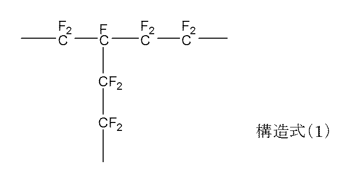
According to the present invention, there is provided a fixing member having a base material, an elastic layer provided on the surface of the base material, and a surface layer provided on the surface of the elastic layer, wherein the surface layer has the following structural formula (1 The contact angle measured by a wet tension test mixture solution containing a tetrafluoroethylene-perfluoroalkyl vinyl ether copolymer having a partial structure represented by) and having a wet tension of 31.0 mN / m is 67. A fuser member having a surface that is greater than or equal to ° is provided:
また、本発明によれば、上記の定着部材と、該定着部材の加熱装置と、該定着部材に対向して配置されている加圧部材とを有する定着装置が提供される。
Further, according to the present invention, there is provided a fixing device having the above-described fixing member, a heating device for the fixing member, and a pressure member disposed to face the fixing member.
また、本発明によれば、上記の定着装置を具備している画像形成装置が提供される。
In addition, according to the present invention, an image forming apparatus provided with the above-described fixing device is provided.
更に、本発明によれば、基材と、
該基材の表面に設けられた弾性層と、
下記構造式(1)で示される部分構造を有しているテトラフルオロエチレン-パーフルオロアルキルビニルエーテル共重合体を含む表層と、を有する定着部材の製造方法であって、
該表層を、下記第一の工程~第三の工程により形成することを特徴とする定着部材の製造方法が提供される:
(1)テトラフルオロエチレン-パーフルオロアルキルビニルエーテル共重合体を含む膜の温度を、該テトラフルオロエチレン-パーフルオロアルキルビニルエーテル共重合体のガラス転移点(Tg)以上、該テトラフルオロエチレン-パーフルオロアルキルビニルエーテル共重合体のTmより30℃高い温度(Tm+30℃)以下の温度範囲に調整する第一の工程、
(2)該第一の工程で温度を調整した該テトラフルオロエチレン-パーフルオロアルキルビニルエーテル共重合体を含む膜の表面に、酸素濃度が1000ppm以下の雰囲気下、電離性放射線を照射し、該樹脂層中の該テトラフルオロエチレン-パーフルオロアルキルビニルエーテル共重合体に、下記構造式(1)で示される部分構造を形成せしめる第二の工程、
(3)該第二の工程によって得られた、下記構造式(1)で示される部分構造を有するテトラフルオロエチレン-パーフルオロアルキルビニルエーテル共重合体を含む膜を、340℃以上380℃以下の温度範囲に調整する第三の工程:

。
Furthermore, according to the present invention, a substrate;
An elastic layer provided on the surface of the substrate;
A surface layer containing a tetrafluoroethylene-perfluoroalkyl vinyl ether copolymer having a partial structure represented by the following structural formula (1), comprising:
There is provided a method for producing a fixing member, wherein the surface layer is formed by the following first to third steps:
(1) The temperature of the film containing the tetrafluoroethylene-perfluoroalkyl vinyl ether copolymer is higher than the glass transition point (Tg) of the tetrafluoroethylene-perfluoroalkyl vinyl ether copolymer, and the tetrafluoroethylene-perfluoroalkyl A first step of adjusting to a temperature range of 30 ° C. higher than the Tm of the vinyl ether copolymer (Tm + 30 ° C.) or less;
(2) The surface of the film containing the tetrafluoroethylene-perfluoroalkyl vinyl ether copolymer whose temperature is adjusted in the first step is irradiated with ionizing radiation in an atmosphere having an oxygen concentration of 1000 ppm or less, and the resin A second step of forming a partial structure represented by the following structural formula (1) on the tetrafluoroethylene-perfluoroalkyl vinyl ether copolymer in the layer;
(3) A film containing a tetrafluoroethylene-perfluoroalkyl vinyl ether copolymer having a partial structure represented by the following structural formula (1) obtained by the second step is heated at a temperature of 340 ° C. or higher and 380 ° C. or lower. Third step to adjust the range:
.
該基材の表面に設けられた弾性層と、
下記構造式(1)で示される部分構造を有しているテトラフルオロエチレン-パーフルオロアルキルビニルエーテル共重合体を含む表層と、を有する定着部材の製造方法であって、
該表層を、下記第一の工程~第三の工程により形成することを特徴とする定着部材の製造方法が提供される:
(1)テトラフルオロエチレン-パーフルオロアルキルビニルエーテル共重合体を含む膜の温度を、該テトラフルオロエチレン-パーフルオロアルキルビニルエーテル共重合体のガラス転移点(Tg)以上、該テトラフルオロエチレン-パーフルオロアルキルビニルエーテル共重合体のTmより30℃高い温度(Tm+30℃)以下の温度範囲に調整する第一の工程、
(2)該第一の工程で温度を調整した該テトラフルオロエチレン-パーフルオロアルキルビニルエーテル共重合体を含む膜の表面に、酸素濃度が1000ppm以下の雰囲気下、電離性放射線を照射し、該樹脂層中の該テトラフルオロエチレン-パーフルオロアルキルビニルエーテル共重合体に、下記構造式(1)で示される部分構造を形成せしめる第二の工程、
(3)該第二の工程によって得られた、下記構造式(1)で示される部分構造を有するテトラフルオロエチレン-パーフルオロアルキルビニルエーテル共重合体を含む膜を、340℃以上380℃以下の温度範囲に調整する第三の工程:
An elastic layer provided on the surface of the substrate;
A surface layer containing a tetrafluoroethylene-perfluoroalkyl vinyl ether copolymer having a partial structure represented by the following structural formula (1), comprising:
There is provided a method for producing a fixing member, wherein the surface layer is formed by the following first to third steps:
(1) The temperature of the film containing the tetrafluoroethylene-perfluoroalkyl vinyl ether copolymer is higher than the glass transition point (Tg) of the tetrafluoroethylene-perfluoroalkyl vinyl ether copolymer, and the tetrafluoroethylene-perfluoroalkyl A first step of adjusting to a temperature range of 30 ° C. higher than the Tm of the vinyl ether copolymer (Tm + 30 ° C.) or less;
(2) The surface of the film containing the tetrafluoroethylene-perfluoroalkyl vinyl ether copolymer whose temperature is adjusted in the first step is irradiated with ionizing radiation in an atmosphere having an oxygen concentration of 1000 ppm or less, and the resin A second step of forming a partial structure represented by the following structural formula (1) on the tetrafluoroethylene-perfluoroalkyl vinyl ether copolymer in the layer;
(3) A film containing a tetrafluoroethylene-perfluoroalkyl vinyl ether copolymer having a partial structure represented by the following structural formula (1) obtained by the second step is heated at a temperature of 340 ° C. or higher and 380 ° C. or lower. Third step to adjust the range:
本発明によれば、高い耐摩耗性を有し、かつ、表面のトナー離型性に優れた定着部材を得ることができる。また、本発明によれば、高品位な電子写真画像の安定的な提供に資する定着装置および画像形成装置を得ることができる。
According to the present invention, it is possible to obtain a fixing member having high wear resistance and excellent surface toner releasability. In addition, according to the present invention, it is possible to obtain a fixing device and an image forming apparatus that contribute to the stable provision of high-quality electrophotographic images.
未架橋のテトラフルオロエチレン-パーフルオロアルキルビニルエーテル共重合体(PFA)を含む膜に対して特許文献1に記載の方法によりPFAを架橋させた場合に、当該膜の表面のトナー離型性が低下する原因を、本発明者らは以下のように考えている。
When a film containing uncrosslinked tetrafluoroethylene-perfluoroalkyl vinyl ether copolymer (PFA) is crosslinked with PFA by the method described in Patent Document 1, toner releasability on the surface of the film is reduced. The present inventors consider the reason for this as follows.
すなわち、溶融状態にあるPFAに対して電子線などを照射した場合、例えば、下記構造式(2)で示されるPFAのパーフルオロアルキルビニルエーテルの分岐部分の結合が特に切断されやすいと考えられる。その結果、膜内には、低分子量成分が生成し、これが膜の表面に存在することによって、電離放射線照射によりPFAを架橋させた膜の表面エネルギーが高くなっているものと推測した。
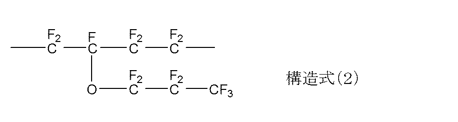
That is, when the molten PFA is irradiated with an electron beam or the like, for example, the bond at the branched portion of the perfluoroalkyl vinyl ether of PFA represented by the following structural formula (2) is considered to be particularly easily broken. As a result, a low molecular weight component was generated in the film, and it was assumed that the surface energy of the film obtained by crosslinking PFA by ionizing radiation irradiation was increased due to the presence of the low molecular weight component on the film surface.
このような推測に基づき、本発明者らは、当該膜中の低分子量成分を、膜の表面から内部に移動させることができれば、当該膜の表面エネルギーを低下させ、当該膜の表面のトナー離型性を向上させられるものと考えた。
Based on such assumptions, if the low molecular weight component in the film can be moved from the surface of the film to the inside, the present inventors reduce the surface energy of the film and remove the toner on the surface of the film. We thought that the formability could be improved.
そこで、本発明者らは、電離放射線の照射によって、下記構造式(1)で示される部分構造(架橋構造)を形成してなるPFAを含む膜の温度を、当該架橋構造を有するPFAの融点以上の温度に調整し、当該膜を実質的な熔融状態に所定の時間置いてみた。その結果、当該膜の表面エネルギーを大幅に低下させることができることを本発明者らは見出した。

これは、当該膜中のPFAを実質的な溶融状態に所定時間置くことで、PFAの分子鎖の流動性が高まり、当該膜中の成分が、当該膜の表面エネルギーを最小化する方向に再配列されたためであると考えられる。
Therefore, the present inventors set the temperature of the film containing PFA formed by forming a partial structure (crosslinked structure) represented by the following structural formula (1) by irradiation with ionizing radiation, and the melting point of the PFA having the crosslinked structure. The temperature was adjusted to the above temperature, and the film was placed in a substantially molten state for a predetermined time. As a result, the present inventors have found that the surface energy of the film can be significantly reduced.
This is because by placing the PFA in the film in a substantially molten state for a predetermined time, the fluidity of the molecular chain of the PFA is increased, and the components in the film are regenerated in a direction that minimizes the surface energy of the film. This is thought to be due to the arrangement.
以下、本発明に係る定着部材とその製造方法について具体的に説明する。
Hereinafter, the fixing member and the manufacturing method thereof according to the present invention will be described in detail.
(定着装置の構成):
以下の説明において、定着装置及びこの定着装置を構成する部材に関し、長手方向とは記録材の面において記録材搬送方向と直交する方向である。短手方向とは、記録材の面において記録材搬送方向と平行な方向である。幅とは短手方向の寸法である。図2は本発明に係る定着部材を有する定着装置6の横断側面構成模式図である。この定着装置6は、フィルム加熱方式の定着装置である。
21は横断面略半円弧状の樋型に形成されたフィルムガイドである。フィルムガイド21は、図面に対し垂直な方向を長手方向とする横長の部材である。22はこのフィルムガイド21の下面の略中央に長手方向に沿って形成された溝内に収容支持されている加熱体である。
23は本発明に係る定着部材であって、ここでは、エンドレスベルト形状(円筒状)を有している。定着部材23は、加熱体22を支持させたガイド21にルーズに外嵌されている。ガイド21の材料は、例えばPPS(ポリフェニレンサルファイト)や液晶ポリマー等の耐熱性樹脂の成形品である。 (Configuration of fixing device):
In the following description, regarding the fixing device and members constituting the fixing device, the longitudinal direction is a direction orthogonal to the recording material conveyance direction on the surface of the recording material. The short side direction is a direction parallel to the recording material conveyance direction on the surface of the recording material. The width is a dimension in the short direction. FIG. 2 is a schematic cross-sectional side view of afixing device 6 having a fixing member according to the present invention. The fixing device 6 is a film heating type fixing device.
Reference numeral 21 denotes a film guide formed in a saddle shape having a substantially semicircular cross section. The film guide 21 is a horizontally long member whose longitudinal direction is a direction perpendicular to the drawing. Reference numeral 22 denotes a heating body that is housed and supported in a groove formed along the longitudinal direction at the approximate center of the lower surface of the film guide 21.
Afixing member 23 according to the present invention has an endless belt shape (cylindrical shape). The fixing member 23 is loosely fitted on the guide 21 that supports the heating body 22. The material of the guide 21 is a molded product of a heat resistant resin such as PPS (polyphenylene sulfite) or a liquid crystal polymer.
以下の説明において、定着装置及びこの定着装置を構成する部材に関し、長手方向とは記録材の面において記録材搬送方向と直交する方向である。短手方向とは、記録材の面において記録材搬送方向と平行な方向である。幅とは短手方向の寸法である。図2は本発明に係る定着部材を有する定着装置6の横断側面構成模式図である。この定着装置6は、フィルム加熱方式の定着装置である。
21は横断面略半円弧状の樋型に形成されたフィルムガイドである。フィルムガイド21は、図面に対し垂直な方向を長手方向とする横長の部材である。22はこのフィルムガイド21の下面の略中央に長手方向に沿って形成された溝内に収容支持されている加熱体である。
23は本発明に係る定着部材であって、ここでは、エンドレスベルト形状(円筒状)を有している。定着部材23は、加熱体22を支持させたガイド21にルーズに外嵌されている。ガイド21の材料は、例えばPPS(ポリフェニレンサルファイト)や液晶ポリマー等の耐熱性樹脂の成形品である。 (Configuration of fixing device):
In the following description, regarding the fixing device and members constituting the fixing device, the longitudinal direction is a direction orthogonal to the recording material conveyance direction on the surface of the recording material. The short side direction is a direction parallel to the recording material conveyance direction on the surface of the recording material. The width is a dimension in the short direction. FIG. 2 is a schematic cross-sectional side view of a
A
定着部材の加熱装置を構成している加熱体22は、全体に低熱容量で且つ長手方向に細長いセラミックス製のヒータである。このヒータ22は、長手方向に細長い薄板状のアルミナ製のヒータ基板221を有している。そしてこのヒータ基板221の表面(後述のニップ部N側の面)には、ヒータ基板221の長手方向に沿って線状あるいは細帯状のAg/Pdなどの通電発熱体(抵抗発熱体)222が形成されている。そしてこの通電発熱体222は、通電発熱体222を覆うように薄いガラス層等によって形成された表面保護層223によって保護されている。ヒータ基板221の裏面(ニップ部N側の面とは反対側の面)には、温度検知部材としてサーミスタ等の検温素子224などが設けられている。
24は加圧部材としての加圧ローラである。この加圧ローラ24は、定着部材23の下方に、定着部材23と対向するように配置されている。そしてこの加圧ローラ24を所定の加圧機構(不図示)により、定着部材23を挟んでヒータ22に対し所定の加圧力で加圧させられている。この加圧力に応じて加圧ローラ24の外周面(表面)と定着部材23の外周面(表面)が接触し加圧ローラ24が弾性変形する。これによって加圧ローラ24表面と定着部材23表面との間に所定幅のニップ部N(定着ニップ部)を形成している。 Theheating element 22 constituting the heating device for the fixing member is a ceramic heater having a low heat capacity as a whole and elongated in the longitudinal direction. The heater 22 has a thin plate-like alumina heater substrate 221 elongated in the longitudinal direction. On the surface of the heater substrate 221 (the surface on the nip portion N side described later), an energization heating element (resistance heating element) 222 such as a linear or narrow strip of Ag / Pd along the longitudinal direction of the heater substrate 221 is provided. Is formed. The energization heating element 222 is protected by a surface protective layer 223 formed of a thin glass layer or the like so as to cover the energization heating element 222. On the back surface of the heater substrate 221 (surface opposite to the surface on the nip portion N side), a temperature detecting element 224 such as a thermistor is provided as a temperature detection member.
Reference numeral 24 denotes a pressure roller as a pressure member. The pressure roller 24 is disposed below the fixing member 23 so as to face the fixing member 23. The pressure roller 24 is pressed against the heater 22 with a predetermined pressure by a predetermined pressure mechanism (not shown) with the fixing member 23 interposed therebetween. In response to this pressure, the outer peripheral surface (surface) of the pressure roller 24 and the outer peripheral surface (surface) of the fixing member 23 come into contact with each other, and the pressure roller 24 is elastically deformed. As a result, a nip portion N (fixing nip portion) having a predetermined width is formed between the surface of the pressure roller 24 and the surface of the fixing member 23.
24は加圧部材としての加圧ローラである。この加圧ローラ24は、定着部材23の下方に、定着部材23と対向するように配置されている。そしてこの加圧ローラ24を所定の加圧機構(不図示)により、定着部材23を挟んでヒータ22に対し所定の加圧力で加圧させられている。この加圧力に応じて加圧ローラ24の外周面(表面)と定着部材23の外周面(表面)が接触し加圧ローラ24が弾性変形する。これによって加圧ローラ24表面と定着部材23表面との間に所定幅のニップ部N(定着ニップ部)を形成している。 The
(定着部材の構成):
図3は、定着部材23の部分断面図である。図3において、231は基材、232は弾性層、233が表層を表す。
<基材>
基材の材質としては、ポリイミド(PI)、ポリアミドイミド(PAI)、ポリエーテルエーテルケトン(PEEK)、ポリエーテルスルホン(PES)等の樹脂材料、ステンレスやニッケルなどの金属材料を用い得る。また、熱容量を小さくし、定着装置としてのクイックスタート性を向上させるために、その厚みは、20~100μm、特には、20~60μmとすることが好ましい。
<弾性層>
弾性層232の材料としては、公知の弾性材料を使用でき、例えば、シリコーンゴム、フッ素ゴム等を用いられる。
<表層>
表層233は、前記構造式(1)で示される部分構造、すなわち、架橋した部分を有するPFA(テトラフルオロエチレン-パーフルオロアルキルビニルエーテル共重合体)を含む。また、表層233の表面は、ぬれ張力が31.0mN/mであるぬれ張力試験用混合液に対する静的接触角度が67度以上である。ここで、67度という静的接触角の値は、トナー等の付着が抑制された、安定な表面を有する定着部材が有する値としては一般的な値である。しかしながら、架橋したPFAを含む表面層であって、かつ、静的接触角が少なくとも67度であるような、安定な表面を有するものこれまで存在していなかったものと本発明者らは認識している。
なお、本発明に係る表面層に係る接触角の上限の値としては、特に限定されないが、現実的には74度程度である。
なお、本発明に係る静的接触角は、ぬれ張力が31.0mN/mであるぬれ張力試験用混合液を用いて測定した。測定装置として、全自動接触角計(商品名:DM-500、協和界面科学株式会社製)を用い、ぬれ張力試験用混合液の被測定表面への滴下量は1.2μlとした。また、本発明に係る接触角の値は、5~7回の測定値の算術平均値とした。、 (Configuration of fixing member):
FIG. 3 is a partial cross-sectional view of the fixingmember 23. In FIG. 3, reference numeral 231 denotes a base material, 232 denotes an elastic layer, and 233 denotes a surface layer.
<Base material>
As the material of the substrate, a resin material such as polyimide (PI), polyamideimide (PAI), polyetheretherketone (PEEK), polyethersulfone (PES), or a metal material such as stainless steel or nickel can be used. Further, in order to reduce the heat capacity and improve the quick start property as a fixing device, the thickness is preferably 20 to 100 μm, particularly 20 to 60 μm.
<Elastic layer>
As a material of theelastic layer 232, a known elastic material can be used, and for example, silicone rubber, fluorine rubber, or the like is used.
<Surface>
Thesurface layer 233 includes PFA (tetrafluoroethylene-perfluoroalkyl vinyl ether copolymer) having a partial structure represented by the structural formula (1), that is, a crosslinked portion. Further, the surface of the surface layer 233 has a static contact angle of 67 degrees or more with respect to a wet tension test mixed liquid having a wet tension of 31.0 mN / m. Here, the value of the static contact angle of 67 degrees is a general value that the fixing member having a stable surface in which the adhesion of toner or the like is suppressed has. However, the present inventors have recognized that a surface layer containing cross-linked PFA and having a stable surface with a static contact angle of at least 67 degrees has never existed. ing.
The upper limit value of the contact angle related to the surface layer according to the present invention is not particularly limited, but is actually about 74 degrees.
In addition, the static contact angle which concerns on this invention was measured using the liquid mixture for a wet tension test whose wet tension is 31.0 mN / m. As a measuring device, a fully automatic contact angle meter (trade name: DM-500, manufactured by Kyowa Interface Science Co., Ltd.) was used, and the dripping amount of the liquid mixture for wet tension test onto the surface to be measured was 1.2 μl. Further, the value of the contact angle according to the present invention was an arithmetic average value of measured values of 5 to 7 times. ,
図3は、定着部材23の部分断面図である。図3において、231は基材、232は弾性層、233が表層を表す。
<基材>
基材の材質としては、ポリイミド(PI)、ポリアミドイミド(PAI)、ポリエーテルエーテルケトン(PEEK)、ポリエーテルスルホン(PES)等の樹脂材料、ステンレスやニッケルなどの金属材料を用い得る。また、熱容量を小さくし、定着装置としてのクイックスタート性を向上させるために、その厚みは、20~100μm、特には、20~60μmとすることが好ましい。
<弾性層>
弾性層232の材料としては、公知の弾性材料を使用でき、例えば、シリコーンゴム、フッ素ゴム等を用いられる。
<表層>
表層233は、前記構造式(1)で示される部分構造、すなわち、架橋した部分を有するPFA(テトラフルオロエチレン-パーフルオロアルキルビニルエーテル共重合体)を含む。また、表層233の表面は、ぬれ張力が31.0mN/mであるぬれ張力試験用混合液に対する静的接触角度が67度以上である。ここで、67度という静的接触角の値は、トナー等の付着が抑制された、安定な表面を有する定着部材が有する値としては一般的な値である。しかしながら、架橋したPFAを含む表面層であって、かつ、静的接触角が少なくとも67度であるような、安定な表面を有するものこれまで存在していなかったものと本発明者らは認識している。
なお、本発明に係る表面層に係る接触角の上限の値としては、特に限定されないが、現実的には74度程度である。
なお、本発明に係る静的接触角は、ぬれ張力が31.0mN/mであるぬれ張力試験用混合液を用いて測定した。測定装置として、全自動接触角計(商品名:DM-500、協和界面科学株式会社製)を用い、ぬれ張力試験用混合液の被測定表面への滴下量は1.2μlとした。また、本発明に係る接触角の値は、5~7回の測定値の算術平均値とした。、 (Configuration of fixing member):
FIG. 3 is a partial cross-sectional view of the fixing
<Base material>
As the material of the substrate, a resin material such as polyimide (PI), polyamideimide (PAI), polyetheretherketone (PEEK), polyethersulfone (PES), or a metal material such as stainless steel or nickel can be used. Further, in order to reduce the heat capacity and improve the quick start property as a fixing device, the thickness is preferably 20 to 100 μm, particularly 20 to 60 μm.
<Elastic layer>
As a material of the
<Surface>
The
The upper limit value of the contact angle related to the surface layer according to the present invention is not particularly limited, but is actually about 74 degrees.
In addition, the static contact angle which concerns on this invention was measured using the liquid mixture for a wet tension test whose wet tension is 31.0 mN / m. As a measuring device, a fully automatic contact angle meter (trade name: DM-500, manufactured by Kyowa Interface Science Co., Ltd.) was used, and the dripping amount of the liquid mixture for wet tension test onto the surface to be measured was 1.2 μl. Further, the value of the contact angle according to the present invention was an arithmetic average value of measured values of 5 to 7 times. ,
(定着部材の作製方法)
以下に本発明に係る定着部材の製造方法を具体的に説明する。
すなわち、本発明に係る定着部材は、基材と、該基材の表面に設けられた弾性層と、前記構造式(1)で示される部分構造を有しているテトラフルオロエチレン-パーフルオロアルキルビニルエーテル共重合体を含む表層とを有する。

(Fixing member manufacturing method)
The method for manufacturing the fixing member according to the present invention will be specifically described below.
That is, the fixing member according to the present invention includes a base material, an elastic layer provided on the surface of the base material, and a tetrafluoroethylene-perfluoroalkyl having a partial structure represented by the structural formula (1). And a surface layer containing a vinyl ether copolymer.
以下に本発明に係る定着部材の製造方法を具体的に説明する。
すなわち、本発明に係る定着部材は、基材と、該基材の表面に設けられた弾性層と、前記構造式(1)で示される部分構造を有しているテトラフルオロエチレン-パーフルオロアルキルビニルエーテル共重合体を含む表層とを有する。
The method for manufacturing the fixing member according to the present invention will be specifically described below.
That is, the fixing member according to the present invention includes a base material, an elastic layer provided on the surface of the base material, and a tetrafluoroethylene-perfluoroalkyl having a partial structure represented by the structural formula (1). And a surface layer containing a vinyl ether copolymer.
そして、かかる定着部材の製造方法としては、下記第一の工程~第三の工程を含む表層の形成工程を有する。
(1)該弾性層の表面に形成した、未架橋のテトラフルオロエチレン-パーフルオロアルキルビニルエーテル共重合体(以降、「テトラフルオロエチレン-パーフルオロアルキルビニルエーテル共重合体」を「PFA」と略記する)を含む膜の温度を、該PFAのガラス転移点(Tg)以上、該PFAのTmより30℃高い温度(Tm+30℃)以下の温度範囲に調整する第一の工程、
(2)該第一の工程にて調整した温度範囲にある、該PFAを含む膜の表面に、酸素濃度が1000ppm以下の雰囲気下、電離性放射線を照射し、該膜中のPFAに上記構造式(1)で示される部分構造を形成せしめる第二の工程、
(3)該第二の工程によって得られた、上記構造式(1)で示される部分構造を有するPFAを含む膜の温度を、340℃以上380℃以下の温度範囲に調整する第三の工程。 The fixing member manufacturing method includes a surface layer forming step including the following first to third steps.
(1) Uncrosslinked tetrafluoroethylene-perfluoroalkyl vinyl ether copolymer formed on the surface of the elastic layer (hereinafter, “tetrafluoroethylene-perfluoroalkyl vinyl ether copolymer” is abbreviated as “PFA”) A first step of adjusting the temperature of the film containing the PFA to a temperature range of not less than the glass transition point (Tg) of the PFA and not more than 30 ° C. higher than the Tm of the PFA (Tm + 30 ° C.);
(2) The surface of the film containing the PFA in the temperature range adjusted in the first step is irradiated with ionizing radiation in an atmosphere having an oxygen concentration of 1000 ppm or less, and the PFA in the film has the structure described above. A second step of forming a partial structure represented by formula (1),
(3) Third step of adjusting the temperature of the film containing PFA having the partial structure represented by the structural formula (1) obtained in the second step to a temperature range of 340 ° C. or higher and 380 ° C. or lower. .
以下、各工程について詳述する。
第一の工程;
まず、弾性層の表面に、未架橋のPFAを含む膜を形成する。次いで、この膜の温度を、未架橋のPFAのガラス転移点(Tg)以上、該PFAの融点(Tm)より30℃高い温度(Tm+30℃)以下の温度範囲に調整する。
ここで、本発明において表層の主たる材料として用いるフッ素樹脂であるPFAは、ポリテトラフルオロエチレン(以降、「PTFE」と略)と同等の耐熱性を持ちながら、PTFEと比べ、溶融粘度が低い。そのため、加工性や平滑性に優れる。
PFAの融点は、パーフルオロアルキルビニルエーテルの重合比、PFAの重合度などによっても多少変化するものの、一般的には、PFAの融点は300℃~310℃の範囲内である。
PFAを含む多くのフッ素樹脂は、常温下での電離性放射線照射では分解反応しか起こらない分解型の樹脂である。しかし、融点近傍まで加熱した状態で電離性放射線を照射すると、分解反応よりも架橋反応が主反応となり分子鎖が架橋し、耐摩耗性が向上することが、特にPTFEで良く知られている。
今回、本発明者らの検討によると、PFAでは融点近傍までの加熱をしなくても、ガラス転移点以上の加熱で十分架橋反応が起こり、耐摩耗性が向上することがわかった。PTFEの場合、剛直で一本鎖に近い分子構造のPTFEを架橋させるためには、融点近傍加熱により、結晶を溶融させ、分子鎖が動きやすい状態で電離性放射線の照射を行う必要がある。しかしPTFEとは異なり、側鎖を持つことで柔軟な非晶部分を有するPFAは、ガラス転移点(Tg)以上で非晶部分が柔軟に動くことができるため、ガラス転移点(Tg)以上で電離性放射線の照射による架橋が可能となると考えられる。そのため、後述する第二の工程としての電離性放射線照射工程に供する、未架橋のPFAを含む膜の温度は、PFAのガラス転移点(Tg)以上とすることが好ましい。
一方、未架橋のPFAの温度を、未架橋のPFAの融点より高くし過ぎると、PFAの分解反応が支配的となる。そこで、後述する第二の工程としての電離性放射線照射工程に供する、未架橋のPFAを含む膜の温度は、未架橋のPFAの融点より30℃高い温度(Tm+30℃)以下、特には、未架橋のPFAの融点より60℃低い温度(Tm-60℃)以下とすることが好ましい。 Hereinafter, each process is explained in full detail.
First step;
First, a film containing uncrosslinked PFA is formed on the surface of the elastic layer. Next, the temperature of this film is adjusted to a temperature range between the glass transition point (Tg) of uncrosslinked PFA and 30 ° C. higher than the melting point (Tm) of the PFA (Tm + 30 ° C.).
Here, PFA, which is a fluororesin used as the main material of the surface layer in the present invention, has a heat resistance equivalent to that of polytetrafluoroethylene (hereinafter abbreviated as “PTFE”), but has a lower melt viscosity than PTFE. Therefore, it is excellent in workability and smoothness.
Although the melting point of PFA varies somewhat depending on the polymerization ratio of perfluoroalkyl vinyl ether, the degree of polymerization of PFA, and the like, generally, the melting point of PFA is in the range of 300 ° C. to 310 ° C.
Many fluororesins including PFA are decomposition-type resins that undergo only a decomposition reaction when irradiated with ionizing radiation at room temperature. However, it is well known in particular for PTFE that irradiation with ionizing radiation in the state heated to the vicinity of the melting point results in the crosslinking reaction becoming the main reaction rather than the decomposition reaction, the molecular chain is crosslinked, and the wear resistance is improved.
According to the study by the present inventors, it has been found that, in PFA, even if heating to the vicinity of the melting point is not performed, the crosslinking reaction occurs sufficiently by heating above the glass transition point, and the wear resistance is improved. In the case of PTFE, in order to cross-link PTFE having a molecular structure that is rigid and has a structure close to a single chain, it is necessary to perform irradiation with ionizing radiation in a state in which the crystals are melted by heating near the melting point and the molecular chain easily moves. However, unlike PTFE, PFA having a flexible amorphous part by having a side chain can move flexibly at the glass transition point (Tg) or higher, so that the glass transition point (Tg) or higher. It is thought that crosslinking by irradiation with ionizing radiation becomes possible. Therefore, it is preferable that the temperature of the film containing uncrosslinked PFA used in an ionizing radiation irradiation process as a second process described later is equal to or higher than the glass transition point (Tg) of PFA.
On the other hand, when the temperature of the uncrosslinked PFA is set higher than the melting point of the uncrosslinked PFA, the decomposition reaction of PFA becomes dominant. Therefore, the temperature of the film containing uncrosslinked PFA used in the ionizing radiation irradiation step as the second step described later is 30 ° C. higher than the melting point of uncrosslinked PFA (Tm + 30 ° C.) or less. The temperature is preferably 60 ° C. lower than the melting point of the crosslinked PFA (Tm−60 ° C.) or lower.
なお、ここで、融点とは、示差走査熱量計(DSC)を用いて、20℃/分の昇温速度で昇温したときに、融解ピークとして検出される結晶融点であると定義する。
また、ここでガラス転移点とは、動的粘弾性測定装置(DMA)を用いて、周波数10Hz、昇温速度5℃/分で測定したときのtanδの変曲点ピークをガラス転移点と定義する。
なお、弾性層表面への、未架橋のPFA樹脂を含む膜の形成方法としては、例えば下記(1)~(3)の方法が挙げられる。
(1)水系溶媒中に、未架橋のPFAからなる粒子(以下、「未架橋PFA粒子」ともいう)がコロイド状に分散しているディスパージョンを、公知の方法、例えば、スプレーコートやディップコートによって、当該ディスパージョンの塗膜を形成する。次いで、該塗膜の温度を、未架橋PFAの融点以上に調整し、未架橋PFA粒子を熔融せしめて未架橋PFAを含む膜を形成する。
(2)粉体塗料を静電塗装により弾性層の表面に付着させる。次いで、該塗膜の温度を、未架橋PFAの融点以上に調整し、未架橋PFA粒子を熔融せしめて未架橋PFAを含む膜を含む膜を形成する。
(3)押出成形によって未架橋PFAを含むチューブ(以降、「未架橋PFAチューブ」ともいう))を作成する。この未架橋PFAチューブを、弾性層の周囲に被覆することによって、弾性層の表面に未架橋のPFAを含む膜を形成する。 Here, the melting point is defined as a crystalline melting point detected as a melting peak when the temperature is increased at a rate of temperature increase of 20 ° C./min using a differential scanning calorimeter (DSC).
Here, the glass transition point is defined as a glass transition point, which is the inflection point peak of tan δ when measured at a frequency of 10 Hz and a heating rate of 5 ° C./min using a dynamic viscoelasticity measuring device (DMA). To do.
Examples of a method for forming a film containing an uncrosslinked PFA resin on the elastic layer surface include the following methods (1) to (3).
(1) A dispersion in which particles of uncrosslinked PFA (hereinafter, also referred to as “uncrosslinked PFA particles”) are dispersed in a colloidal form in an aqueous solvent is subjected to a known method such as spray coating or dip coating. To form a coating film of the dispersion. Next, the temperature of the coating film is adjusted to be equal to or higher than the melting point of uncrosslinked PFA, and the uncrosslinked PFA particles are melted to form a film containing uncrosslinked PFA.
(2) A powder coating is adhered to the surface of the elastic layer by electrostatic coating. Next, the temperature of the coating film is adjusted to be equal to or higher than the melting point of the uncrosslinked PFA, and the uncrosslinked PFA particles are melted to form a film including a film containing the uncrosslinked PFA.
(3) A tube containing uncrosslinked PFA (hereinafter also referred to as “uncrosslinked PFA tube”)) is prepared by extrusion molding. By covering this uncrosslinked PFA tube around the elastic layer, a film containing uncrosslinked PFA is formed on the surface of the elastic layer.
第二の工程;
本工程は、上記第一の工程にて調整した温度範囲にある、未架橋のPFAを含む膜の表面に、酸素濃度が1000ppm以下の雰囲気下、電離性放射線を照射して、PFAに前記構造式(1)で示される部分構造を形成せしめる工程である。
本工程で用いる電離性放射線としては、γ線、電子線、X線、中性子線、あるいは高エネルギーイオン等が挙げられる。中でも、装置の汎用性の観点から、電子線が好ましい。
放射線の照射線量の目安としては、1~1000kGy、特には、200~600kGyの範囲内で、未架橋のPFAに前記構造式(1)で示される架橋構造を形成させるに必要な量を適宜選択すればよい。照射線量を上記の範囲内で設定することで、PFAの分子鎖が切断されることによって生成する低分子量成分の揮発によるPFAの重量減少を抑制することができる。
本工程に係る電離性放射線の照射は、未架橋のPFAを含む膜を、酸素が実質的に不在の雰囲気下で行うことが必要である。具体的な雰囲気としては、酸素濃度が1000ppm以下が好ましい。酸素濃度が1000ppm以下であれば、真空下、窒素、アルゴン等の不活性ガス雰囲気下で行なってもよい。コスト面から、窒素雰囲気下が好ましい。 Second step;
In this step, the surface of the film containing uncrosslinked PFA in the temperature range adjusted in the first step is irradiated with ionizing radiation in an atmosphere having an oxygen concentration of 1000 ppm or less, and the structure is applied to the PFA. This is a step of forming a partial structure represented by the formula (1).
Examples of the ionizing radiation used in this step include γ rays, electron beams, X rays, neutron rays, high energy ions, and the like. Among these, an electron beam is preferable from the viewpoint of versatility of the apparatus.
As a guideline for the radiation dose, an amount necessary for forming a crosslinked structure represented by the structural formula (1) on uncrosslinked PFA within a range of 1 to 1000 kGy, particularly 200 to 600 kGy, is appropriately selected. do it. By setting the irradiation dose within the above range, it is possible to suppress the weight loss of the PFA due to the volatilization of the low molecular weight component generated by breaking the molecular chain of the PFA.
Irradiation with ionizing radiation according to this step requires that a film containing uncrosslinked PFA be performed in an atmosphere substantially free of oxygen. As a specific atmosphere, an oxygen concentration of 1000 ppm or less is preferable. If oxygen concentration is 1000 ppm or less, you may carry out in inert gas atmosphere, such as nitrogen and argon, under a vacuum. In terms of cost, a nitrogen atmosphere is preferable.
第三の工程;
本工程では、上記第二の工程によって得られた、上記構造式(1)で示される部分構造、すなわち、架橋構造を有するPFAを含む膜を、更に340~380℃の温度範囲に調整する。この工程は、第二の工程を行った装置内において引き続いて、窒素雰囲気下で行ってもよく、また、大気中で行ってもよい。また、第二の工程を経た膜を、一旦常温に冷却した後に、再び、340~380℃の温度範囲に加熱してもよい。
この工程を経ることで、電離性放射線照射後の、架橋したPFAを含む膜の表面のトナー離型性を改善することができる。
未架橋PFAの融点近傍に調整した、未架橋PFAを含む膜に対して電離性放射線を照射した後の当該膜の表面のトナー離型性の低下は、PFA中のパーフルオロアルキルビニルエーテル基の分解に伴う、高表面エネルギー成分の生成によるものと考えられる。そして、本工程において、架橋PFAを含む膜を、架橋PFAの融点以上の温度範囲に調整することで、架橋PFAの分子鎖の流動性を高め、表面エネルギーを最小化するように分子の再配列が促されるものと考えられる。その結果、架橋PFAを含む膜中の、表面エネルギーの高い成分が、当該膜中の内部に移動し、表面エネルギーの低い架橋PFAが表面側に移動することで、一旦低下した当該膜のトナー離型性が回復するものと考えられる。
本工程における、架橋PFAを含む膜の温度範囲である340~380℃は、架橋PFAの結晶が十分に流動し、かつ、架橋PFAの分解が実質的に生じない温度であると考えられる。
なお、本工程においては、架橋PFAを含む膜を340~380℃の温度範囲に、5分以上維持することが好ましく、特には、10分以上維持することが好ましい。これによって、架橋PFAの分子が流動し易くなり、表面エネルギーの十分な低下を図ることができる。この温度範囲内に維持する時間の上限の目安としては、20分以下とすることが好ましい。 Third step;
In this step, the film containing PFA having the partial structure represented by the structural formula (1), that is, the crosslinked structure, obtained in the second step is further adjusted to a temperature range of 340 to 380 ° C. This step may be performed in a nitrogen atmosphere or in the air, subsequently in the apparatus in which the second step has been performed. Further, the film that has undergone the second step may be once cooled to room temperature and then heated again to a temperature range of 340 to 380 ° C.
By passing through this step, it is possible to improve toner releasability on the surface of the film containing crosslinked PFA after irradiation with ionizing radiation.
The decrease in toner releasability on the surface of the film after irradiation with ionizing radiation on a film containing uncrosslinked PFA, which is adjusted near the melting point of uncrosslinked PFA, is caused by decomposition of perfluoroalkyl vinyl ether groups in PFA. This is thought to be due to the generation of high surface energy components. In this step, the molecular rearrangement is performed so as to increase the fluidity of the molecular chain of the crosslinked PFA and minimize the surface energy by adjusting the film containing the crosslinked PFA to a temperature range higher than the melting point of the crosslinked PFA. Is considered to be encouraged. As a result, the component having a high surface energy in the film containing the crosslinked PFA moves into the film, and the crosslinked PFA having a low surface energy moves to the surface side. It is considered that the formality is restored.
The temperature range of 340 to 380 ° C. of the film containing crosslinked PFA in this step is considered to be a temperature at which crosslinked PFA crystals flow sufficiently and decomposition of crosslinked PFA does not substantially occur.
In this step, it is preferable to maintain the film containing crosslinked PFA in the temperature range of 340 to 380 ° C. for 5 minutes or more, and particularly preferably for 10 minutes or more. Thereby, the molecules of the crosslinked PFA can easily flow, and the surface energy can be sufficiently reduced. As a guideline of the upper limit of the time to be maintained within this temperature range, it is preferable to set it to 20 minutes or less.
(画像形成装置全体の構成)
図1は本発明に係る像加熱装置を定着装置(定着器)として搭載する画像形成装置の一例の概略構成模式図である。この画像形成装置は電子写真式のレーザービームプリンタ(以下、プリンタと記す)である。
図1に示すプリンタは、像担持体として回転ドラム型の電子写真感光体(以下、感光ドラムと記す)1を有する。
感光ドラム1は、プリント指令に応じて矢印方向に所定の周速度(プロセススピード)にて回転される。そしてこの回転過程で感光ドラム1の外周面(表面)が帯電手段としての帯電ローラ2により所定の極性・電位に一様に帯電処理される。その感光ドラム1の表面の一様帯電面に対してレーザービームスキャナ3から出力される、画像情報に応じて変調制御(ON/OFF制御)されたレーザービームLBによる走査露光がなされる。これによって感光ドラム1の表面に目的の画像情報に応じた静電潜像が形成される。この潜像が現像手段としての現像装置4によりトナーTOを用いてトナー画像として現像され可視化される。 (Configuration of the entire image forming apparatus)
FIG. 1 is a schematic configuration diagram of an example of an image forming apparatus in which the image heating apparatus according to the present invention is mounted as a fixing device (fixing device). This image forming apparatus is an electrophotographic laser beam printer (hereinafter referred to as a printer).
The printer shown in FIG. 1 has a rotating drum type electrophotographic photosensitive member (hereinafter referred to as a photosensitive drum) 1 as an image carrier.
The photosensitive drum 1 is rotated at a predetermined peripheral speed (process speed) in the arrow direction in accordance with a print command. In this rotation process, the outer peripheral surface (surface) of the photosensitive drum 1 is uniformly charged to a predetermined polarity and potential by a chargingroller 2 as a charging means. Scanning exposure is performed on the uniformly charged surface of the surface of the photosensitive drum 1 by the laser beam LB output from the laser beam scanner 3 and subjected to modulation control (ON / OFF control) according to image information. As a result, an electrostatic latent image corresponding to the target image information is formed on the surface of the photosensitive drum 1. This latent image is developed and visualized as a toner image using the toner TO by the developing device 4 as a developing means.
図1は本発明に係る像加熱装置を定着装置(定着器)として搭載する画像形成装置の一例の概略構成模式図である。この画像形成装置は電子写真式のレーザービームプリンタ(以下、プリンタと記す)である。
図1に示すプリンタは、像担持体として回転ドラム型の電子写真感光体(以下、感光ドラムと記す)1を有する。
感光ドラム1は、プリント指令に応じて矢印方向に所定の周速度(プロセススピード)にて回転される。そしてこの回転過程で感光ドラム1の外周面(表面)が帯電手段としての帯電ローラ2により所定の極性・電位に一様に帯電処理される。その感光ドラム1の表面の一様帯電面に対してレーザービームスキャナ3から出力される、画像情報に応じて変調制御(ON/OFF制御)されたレーザービームLBによる走査露光がなされる。これによって感光ドラム1の表面に目的の画像情報に応じた静電潜像が形成される。この潜像が現像手段としての現像装置4によりトナーTOを用いてトナー画像として現像され可視化される。 (Configuration of the entire image forming apparatus)
FIG. 1 is a schematic configuration diagram of an example of an image forming apparatus in which the image heating apparatus according to the present invention is mounted as a fixing device (fixing device). This image forming apparatus is an electrophotographic laser beam printer (hereinafter referred to as a printer).
The printer shown in FIG. 1 has a rotating drum type electrophotographic photosensitive member (hereinafter referred to as a photosensitive drum) 1 as an image carrier.
The photosensitive drum 1 is rotated at a predetermined peripheral speed (process speed) in the arrow direction in accordance with a print command. In this rotation process, the outer peripheral surface (surface) of the photosensitive drum 1 is uniformly charged to a predetermined polarity and potential by a charging
一方、給送ローラ8の駆動により給送カセット9内に積載収納されている記録材Pが一枚ずつ繰り出されガイド10を有するシートパスを通ってレジストローラ11に搬送される。レジストローラ11は、この記録材Pを感光ドラム1の表面と転写ローラ5の外周面(表面)との間の転写ニップ部に所定の制御タイミングにて給送する。この記録材Pは転写ニップ部で挟持搬送され、この搬送過程において転写ローラ5に印加される転写バイアスによって感光ドラム1の表面のトナー画像が順次に記録材Pの面に転写されていく。これによって記録材Pは未定着のトナー画像を担持する。
未定着トナー画像(未定着画像)を担持した記録材Pは感光ドラム1の表面から順次に分離して転写ニップ部から排出され、搬送ガイド12を通じて定着装置6のニップ部に導入される。この記録材Pは定着装置6のニップ部で熱と圧力を受けることによってトナー画像が記録材Pの面に加熱定着される。定着装置6を出た記録材Pは、搬送ローラ13とガイド14と排出ローラ15とを有するシートパスを通って、排出トレイ16にプリントアウトされる。また記録材分離後の感光ドラム1の表面は、クリーニング手段としてのクリーニング装置7により転写残りトナー等の付着汚染物の除去処理を受けて清浄面化され、繰り返して作像に供される。 On the other hand, the recording material P loaded and stored in the feedingcassette 9 is fed one by one by driving the feeding roller 8 and conveyed to the registration roller 11 through a sheet path having a guide 10. The registration roller 11 feeds the recording material P to the transfer nip portion between the surface of the photosensitive drum 1 and the outer peripheral surface (surface) of the transfer roller 5 at a predetermined control timing. The recording material P is nipped and conveyed at the transfer nip portion, and the toner image on the surface of the photosensitive drum 1 is sequentially transferred onto the surface of the recording material P by a transfer bias applied to the transfer roller 5 in the conveyance process. As a result, the recording material P carries an unfixed toner image.
The recording material P carrying an unfixed toner image (unfixed image) is sequentially separated from the surface of the photosensitive drum 1, discharged from the transfer nip portion, and introduced into the nip portion of the fixingdevice 6 through the conveyance guide 12. The recording material P is heated and fixed on the surface of the recording material P by receiving heat and pressure at the nip portion of the fixing device 6. The recording material P that has exited the fixing device 6 passes through a sheet path having a conveying roller 13, a guide 14, and a discharge roller 15, and is printed out on the discharge tray 16. Further, the surface of the photosensitive drum 1 after separation of the recording material is subjected to a removal process of adhering contaminants such as transfer residual toner by a cleaning device 7 as a cleaning unit, and is repeatedly used for image formation.
未定着トナー画像(未定着画像)を担持した記録材Pは感光ドラム1の表面から順次に分離して転写ニップ部から排出され、搬送ガイド12を通じて定着装置6のニップ部に導入される。この記録材Pは定着装置6のニップ部で熱と圧力を受けることによってトナー画像が記録材Pの面に加熱定着される。定着装置6を出た記録材Pは、搬送ローラ13とガイド14と排出ローラ15とを有するシートパスを通って、排出トレイ16にプリントアウトされる。また記録材分離後の感光ドラム1の表面は、クリーニング手段としてのクリーニング装置7により転写残りトナー等の付着汚染物の除去処理を受けて清浄面化され、繰り返して作像に供される。 On the other hand, the recording material P loaded and stored in the feeding
The recording material P carrying an unfixed toner image (unfixed image) is sequentially separated from the surface of the photosensitive drum 1, discharged from the transfer nip portion, and introduced into the nip portion of the fixing
(定着装置の加熱定着動作)
プリント指令に応じて駆動源としての定着モータMが回転駆動されると、この定着モータMの回転力が動力伝達機構(不図示)を介して加圧ローラ24に伝達される。これにより加圧ローラ24は矢印方向に所定の周速度(プロセススピード)で回転される。この加圧ローラ24の回転はニップ部Nを通じて定着フィルム23表面に伝わり、定着フィルム23は加圧ローラ24の回転に従動して矢印方向に回転する。 (Heat fixing operation of fixing device)
When the fixing motor M as a drive source is driven to rotate in response to the print command, the rotational force of the fixing motor M is transmitted to thepressure roller 24 via a power transmission mechanism (not shown). Thus, the pressure roller 24 is rotated at a predetermined peripheral speed (process speed) in the direction of the arrow. The rotation of the pressure roller 24 is transmitted to the surface of the fixing film 23 through the nip portion N, and the fixing film 23 is rotated in the arrow direction following the rotation of the pressure roller 24.
プリント指令に応じて駆動源としての定着モータMが回転駆動されると、この定着モータMの回転力が動力伝達機構(不図示)を介して加圧ローラ24に伝達される。これにより加圧ローラ24は矢印方向に所定の周速度(プロセススピード)で回転される。この加圧ローラ24の回転はニップ部Nを通じて定着フィルム23表面に伝わり、定着フィルム23は加圧ローラ24の回転に従動して矢印方向に回転する。 (Heat fixing operation of fixing device)
When the fixing motor M as a drive source is driven to rotate in response to the print command, the rotational force of the fixing motor M is transmitted to the
以下に、実施例を挙げて、本発明をより具体的に説明する。なお、これら実施例は、本発明を適用できる実施形態の一例ではあるものの、本発明はこれら実施例にのみ限定されるものではなく、本発明の思想の範囲内において種々の変形が可能である。
Hereinafter, the present invention will be described more specifically with reference to examples. Although these examples are examples of embodiments to which the present invention can be applied, the present invention is not limited to these examples, and various modifications are possible within the scope of the idea of the present invention. .
(実施例1)
定着フィルムの基材として、外径30mm、肉厚40μm、軸方向の長さ400mmのステンレス製フィルムを用意した。
このステンレス製フィルム上に、付加硬化型シリコーンゴムを含む液状シリコーンゴム混合物(商品名:XE15-B9236、モメンティブ・パフォーマンス・マテリアルズ・ジャパン社製)を、リング形状の塗工ヘッドを用いて塗布し、液状シリコーンゴム混合物の塗膜を形成した。この塗膜の厚さは300μmであった。次いで、該塗膜を200℃に加熱し、塗膜中の付加硬化型シリコーンゴムを反応させ、シリコーンゴムを含む弾性層を形成した。
次に、弾性層の表面をエキシマUVで処理した後、プライマー(商品名:EK-1909S21L、ダイキン工業株式会社製)を厚み2μmとなるように均一にスプレーコートし、乾燥させた。
次いで、焼成後の厚みが25μmとなるようにPFA粒子の水系分散塗料(商品名:AW-5000L、ダイキン工業株式会社製、融点300℃、ガラス転移点90℃)をスプレーコートして、PFA粒子が分散されてなる塗膜を厚さ50μmに形成した。この塗膜を350℃に加熱し、この温度に15分間維持して該塗膜中のPFA粒子を熔融せしめて、未架橋のPFA樹脂からなる膜とした。 (Example 1)
As a base material for the fixing film, a stainless steel film having an outer diameter of 30 mm, a wall thickness of 40 μm, and an axial length of 400 mm was prepared.
On this stainless steel film, a liquid silicone rubber mixture (trade name: XE15-B9236, manufactured by Momentive Performance Materials Japan) containing addition-curable silicone rubber is applied using a ring-shaped coating head. A coating of a liquid silicone rubber mixture was formed. The thickness of this coating film was 300 μm. Next, the coating film was heated to 200 ° C., and the addition-curable silicone rubber in the coating film was reacted to form an elastic layer containing silicone rubber.
Next, after the surface of the elastic layer was treated with excimer UV, a primer (trade name: EK-1909S21L, manufactured by Daikin Industries, Ltd.) was spray-coated uniformly to a thickness of 2 μm and dried.
Next, PFA particles are spray-coated with an aqueous dispersion paint of PFA particles (trade name: AW-5000L, manufactured by Daikin Industries, Ltd., melting point 300 ° C., glass transition point 90 ° C.) so that the thickness after firing is 25 μm. Was formed to a thickness of 50 μm. This coating film was heated to 350 ° C. and maintained at this temperature for 15 minutes to melt the PFA particles in the coating film to form a film made of uncrosslinked PFA resin.
(第一の工程)
こうして、弾性層と、弾性層の表面に形成された未架橋のPFA樹脂の膜とがこの順に積層されたステンレス製フィルムを、酸素濃度を1000ppm以下とした加熱炉に入れ、未架橋のPFA樹脂の膜の温度を310℃とした。
(第二の工程)
第一の工程により、温度が310℃の状態にある該PFA樹脂の膜の表面に対して電子線を、照射線量が200kGyとなるように照射した。 (First step)
Thus, the stainless steel film in which the elastic layer and the uncrosslinked PFA resin film formed on the surface of the elastic layer are laminated in this order is placed in a heating furnace having an oxygen concentration of 1000 ppm or less, and the uncrosslinked PFA resin is obtained. The temperature of the film was 310 ° C.
(Second step)
In the first step, the surface of the PFA resin film at a temperature of 310 ° C. was irradiated with an electron beam so that the irradiation dose was 200 kGy.
(第三の工程)
電子線の照射終了後、加熱炉から該ステンレス製フィルムを取り出し、大気雰囲気の別の加熱炉に入れて、大気雰囲気下で、PFA樹脂の膜の温度を350℃に加熱して、15分間当該温度を維持して、本発明に係る定着フィルムを得た。そしてこの定着フィルムを後述する評価1~評価4に供した。 (Third process)
After the irradiation with the electron beam, the stainless steel film is taken out from the heating furnace, put into another heating furnace having an air atmosphere, and the temperature of the film of the PFA resin is heated to 350 ° C. in the air atmosphere, for 15 minutes. The fixing film according to the present invention was obtained while maintaining the temperature. The fixing film was subjected to Evaluations 1 to 4 described later.
<評価1> 第二の工程によって得られたPFA樹脂中の架橋構造の分析;
PFA樹脂中の前記構造式(1)で示される構造の存在は、架橋構造の有無については、フッ素核を利用する核磁気共鳴分光法(19F-NMR)によって確認することができる。フッ素樹脂は溶ける溶媒を持たないので、測定は固体状態のまま行われる。PFAは、下記構造式(2)で示されるように、主鎖は直鎖状であり、側鎖部分以外は分岐構造を持たないことが知られている。

<Evaluation 1> Analysis of the crosslinked structure in the PFA resin obtained by the second step;
The presence of the structure represented by the structural formula (1) in the PFA resin can be confirmed by the nuclear magnetic resonance spectroscopy (19F-NMR) using a fluorine nucleus as to the presence or absence of the crosslinked structure. Since the fluororesin does not have a soluble solvent, the measurement is performed in a solid state. As shown in the following structural formula (2), PFA is known to have a linear main chain and no branched structure other than the side chain portion.
PFA樹脂中の前記構造式(1)で示される構造の存在は、架橋構造の有無については、フッ素核を利用する核磁気共鳴分光法(19F-NMR)によって確認することができる。フッ素樹脂は溶ける溶媒を持たないので、測定は固体状態のまま行われる。PFAは、下記構造式(2)で示されるように、主鎖は直鎖状であり、側鎖部分以外は分岐構造を持たないことが知られている。
The presence of the structure represented by the structural formula (1) in the PFA resin can be confirmed by the nuclear magnetic resonance spectroscopy (19F-NMR) using a fluorine nucleus as to the presence or absence of the crosslinked structure. Since the fluororesin does not have a soluble solvent, the measurement is performed in a solid state. As shown in the following structural formula (2), PFA is known to have a linear main chain and no branched structure other than the side chain portion.
ここで、低酸素雰囲気下で、融点近傍にまで加熱した未架橋のPFAに対して電子線を照射すると、PFAの分子鎖が切断され、架橋が起こり、下記構造式(1)で示されるのような分岐構造が新たに形成される。

Here, when an uncrosslinked PFA heated to near the melting point is irradiated with an electron beam in a low oxygen atmosphere, the molecular chain of the PFA is cut and crosslinking occurs, which is represented by the following structural formula (1). Such a branched structure is newly formed.
このようにして新たに形成されてなる、構造式(1)で示される部分構造中に新たに形成される三級炭素の隣の炭素上のフッ素は、19F-NMRスペクトルにおいて、-103ppm付近にピークを持つ。従って、19F-NMRスペクトルにおける、-103ppm付近への新たなこのピーク(架橋点ピーク)の出現をもって、上記構造式(1)で示される部分構造がPFA中に存在することを確認することができ、架橋構造の有無を判別できる。また、このときの測定温度は250℃で、ピーク値は外部標準として六フッ化ベンゼンを用いて決定されている。
実施例1において、第二の工程を経て得られた定着フィルムの表層中のPFAの分子内に上記構造式(1)で示される部分構造が形成されていることを確認するために、表層の一部を切り出し、19F-NMRで分析した。その結果、-103ppm近傍に新たなピークの発現が認められた。 The fluorine on the carbon next to the tertiary carbon newly formed in the partial structure represented by the structural formula (1) newly formed in this manner is around −103 ppm in the 19F-NMR spectrum. With a peak. Therefore, in the 19F-NMR spectrum, it is possible to confirm that the partial structure represented by the above structural formula (1) is present in the PFA with the appearance of this new peak (crosslink point peak) around −103 ppm. The presence or absence of a crosslinked structure can be determined. Moreover, the measurement temperature at this time is 250 degreeC, and the peak value is determined using hexafluorobenzene as an external standard.
In Example 1, in order to confirm that the partial structure represented by the structural formula (1) was formed in the PFA molecule in the surface layer of the fixing film obtained through the second step, A part was cut out and analyzed by 19F-NMR. As a result, a new peak was observed in the vicinity of −103 ppm.
<評価2>. 表層の表面の接触角の測定;
接触角の測定については、ぬれ張力が31.0mN/mである、ぬれ張力試験用混合液(商品名:ぬれ張力試験用混合液No.31.0、和光純薬工業株式会社製)を使用して行った。 <Evaluation 2>. Measurement of the contact angle of the surface of the surface layer;
For measurement of the contact angle, a wet tension test mixed liquid (trade name: mixed liquid for wet tension test No. 31.0, manufactured by Wako Pure Chemical Industries, Ltd.) having a wet tension of 31.0 mN / m is used. I went there.
接触角の測定については、ぬれ張力が31.0mN/mである、ぬれ張力試験用混合液(商品名:ぬれ張力試験用混合液No.31.0、和光純薬工業株式会社製)を使用して行った。 <
For measurement of the contact angle, a wet tension test mixed liquid (trade name: mixed liquid for wet tension test No. 31.0, manufactured by Wako Pure Chemical Industries, Ltd.) having a wet tension of 31.0 mN / m is used. I went there.
<評価3>. 表層の摩耗量の測定;
表層の摩耗の評価は以下のようにして行った。すなわち、作製した定着フィルムを図2に示した構造の定着装置を備えたカラーレーザプリンタ(商品名:LBP5910、キヤノン社製)の定着フィルムとして装着した。このカラーレーザプリンタに、A4サイズの普通紙(商品名:CS-814、キヤノン社製)を横送りで15万枚通紙し、当該普通紙上に、イエロー、マゼンダ、シアン、ブラックの4色のラインパターンを印字した。その後、表層の表面の、当該普通紙の長手方向両端部が接触した部分の摩耗量を測定した。この部分の摩耗量を測定した理由は、この部分が、普通紙の端部との摩擦によって最も摩耗する部分だからである。 <Evaluation 3>. Measurement of surface wear;
Evaluation of surface abrasion was performed as follows. That is, the produced fixing film was mounted as a fixing film of a color laser printer (trade name: LBP5910, manufactured by Canon Inc.) equipped with a fixing device having the structure shown in FIG. Through this color laser printer, 150,000 sheets of A4 size plain paper (trade name: CS-814, manufactured by Canon Inc.) are fed in the horizontal direction, and four colors of yellow, magenta, cyan, and black are passed on the plain paper. A line pattern was printed. Thereafter, the wear amount of the surface layer surface where the both ends in the longitudinal direction of the plain paper contacted was measured. The reason for measuring the amount of wear in this part is that this part is the part that is most worn by friction with the edge of plain paper.
表層の摩耗の評価は以下のようにして行った。すなわち、作製した定着フィルムを図2に示した構造の定着装置を備えたカラーレーザプリンタ(商品名:LBP5910、キヤノン社製)の定着フィルムとして装着した。このカラーレーザプリンタに、A4サイズの普通紙(商品名:CS-814、キヤノン社製)を横送りで15万枚通紙し、当該普通紙上に、イエロー、マゼンダ、シアン、ブラックの4色のラインパターンを印字した。その後、表層の表面の、当該普通紙の長手方向両端部が接触した部分の摩耗量を測定した。この部分の摩耗量を測定した理由は、この部分が、普通紙の端部との摩擦によって最も摩耗する部分だからである。 <
Evaluation of surface abrasion was performed as follows. That is, the produced fixing film was mounted as a fixing film of a color laser printer (trade name: LBP5910, manufactured by Canon Inc.) equipped with a fixing device having the structure shown in FIG. Through this color laser printer, 150,000 sheets of A4 size plain paper (trade name: CS-814, manufactured by Canon Inc.) are fed in the horizontal direction, and four colors of yellow, magenta, cyan, and black are passed on the plain paper. A line pattern was printed. Thereafter, the wear amount of the surface layer surface where the both ends in the longitudinal direction of the plain paper contacted was measured. The reason for measuring the amount of wear in this part is that this part is the part that is most worn by friction with the edge of plain paper.
<評価4>. トナー離型性の評価;
トナー離型性については、作製した定着フィルムをカラーレーザプリンタ(商品名:LBP5910、キヤノン社製)の定着装置に組み込んだ。そして、このカラーレーザプリンタを用いて電子写真画像を連続出力した。電子写真画像としては、A4サイズの普通紙(商品名:CS-814、キヤノン社製)上にイエロー、マゼンダ、シアン、ブラックの4色のラインパターンを形成するものとした。そして、形成された電子写真画像におけるトナーのオフセットの有無を目視で観察し、トナーのオフセットが観察される電子写真画像が最初に出力されたときの枚数を記録した。
但し、150000(150K)枚の電子写真画像の連続出力によってもトナーのオフセットが生じた電子写真画像が観察されなかった場合には、その時点で電子写真画像の形成を終了した。 <Evaluation 4>. Evaluation of toner releasability;
For toner releasability, the prepared fixing film was incorporated into a fixing device of a color laser printer (trade name: LBP5910, manufactured by Canon Inc.). The color laser printer was used to continuously output electrophotographic images. As an electrophotographic image, a line pattern of four colors of yellow, magenta, cyan, and black was formed on A4 size plain paper (trade name: CS-814, manufactured by Canon Inc.). Then, the presence or absence of toner offset in the formed electrophotographic image was visually observed, and the number of sheets when the electrophotographic image in which toner offset was observed was first output was recorded.
However, when an electrophotographic image with toner offset was not observed even after continuous output of 150,000 (150K) electrophotographic images, formation of the electrophotographic image was terminated at that point.
トナー離型性については、作製した定着フィルムをカラーレーザプリンタ(商品名:LBP5910、キヤノン社製)の定着装置に組み込んだ。そして、このカラーレーザプリンタを用いて電子写真画像を連続出力した。電子写真画像としては、A4サイズの普通紙(商品名:CS-814、キヤノン社製)上にイエロー、マゼンダ、シアン、ブラックの4色のラインパターンを形成するものとした。そして、形成された電子写真画像におけるトナーのオフセットの有無を目視で観察し、トナーのオフセットが観察される電子写真画像が最初に出力されたときの枚数を記録した。
但し、150000(150K)枚の電子写真画像の連続出力によってもトナーのオフセットが生じた電子写真画像が観察されなかった場合には、その時点で電子写真画像の形成を終了した。 <
For toner releasability, the prepared fixing film was incorporated into a fixing device of a color laser printer (trade name: LBP5910, manufactured by Canon Inc.). The color laser printer was used to continuously output electrophotographic images. As an electrophotographic image, a line pattern of four colors of yellow, magenta, cyan, and black was formed on A4 size plain paper (trade name: CS-814, manufactured by Canon Inc.). Then, the presence or absence of toner offset in the formed electrophotographic image was visually observed, and the number of sheets when the electrophotographic image in which toner offset was observed was first output was recorded.
However, when an electrophotographic image with toner offset was not observed even after continuous output of 150,000 (150K) electrophotographic images, formation of the electrophotographic image was terminated at that point.
(実施例2)
電子線の照射量を400kGyとした以外は実施例1と同様にして本発明に係る定着フィルムを作製し、評価1~評価4に供した。 (Example 2)
A fixing film according to the present invention was produced in the same manner as in Example 1 except that the irradiation amount of the electron beam was 400 kGy, and it was subjected to Evaluations 1 to 4.
電子線の照射量を400kGyとした以外は実施例1と同様にして本発明に係る定着フィルムを作製し、評価1~評価4に供した。 (Example 2)
A fixing film according to the present invention was produced in the same manner as in Example 1 except that the irradiation amount of the electron beam was 400 kGy, and it was subjected to Evaluations 1 to 4.
(実施例3)
電子線の照射量を600kGyとした以外は実施例1と同様にして本発明に係る定着フィルムを作製し、評価1~4に供した。
(実施例4)
電子線照射時の温度を90℃とした以外は実施例1と同様にして本発明に係る定着フィルムを作製し、評価1~4に供した。
(実施例5)
電子線照射時の温度を150℃とした以外は実施例1と同様にして本発明に係る定着フィルムを作製し、評価1~4に供した。
(実施例6)
電子線照射時の温度を240℃とした以外は実施例1と同様にして本発明に係る定着フィルムを作製し、評価1~4に供した。
(比較例1)
電子線照射時の温度を20℃とした以外は実施例1と同様にして本発明に係る定着フィルムを作製し、評価1~4に供した。 (Example 3)
A fixing film according to the present invention was produced in the same manner as in Example 1 except that the irradiation amount of the electron beam was 600 kGy, and used for evaluations 1 to 4.
Example 4
A fixing film according to the present invention was produced in the same manner as in Example 1 except that the temperature at the time of electron beam irradiation was 90 ° C., and used for evaluations 1 to 4.
(Example 5)
A fixing film according to the present invention was produced in the same manner as in Example 1 except that the temperature at the time of electron beam irradiation was 150 ° C., and used for evaluations 1 to 4.
(Example 6)
A fixing film according to the present invention was produced in the same manner as in Example 1 except that the temperature at the time of electron beam irradiation was 240 ° C., and used for evaluations 1 to 4.
(Comparative Example 1)
A fixing film according to the present invention was produced in the same manner as in Example 1 except that the temperature at the time of electron beam irradiation was 20 ° C., and used for evaluations 1 to 4.
(比較例2)
定着部材の基材として、外径30mm、肉厚40μm、軸方向の長さ400mmのステンレス製フィルムを用意した。
前記ステンレス製フィルム上に、厚み300μmのシリコーンゴムからなる弾性層を形成した。この弾性層の表面をエキシマUVで処理した後、プライマー(商品名:EK-1909S21L、ダイキン工業株式会社製)を厚み2μmとなるように均一にスプレーコートし、乾燥させた。得られたフィルム上に、焼成後の厚みが25μmとなるようにPFA塗料(商品名:AW-5000L、ダイキン工業株式会社製)を均一にスプレーコートした後、350℃、15分間焼成し、表層を形成した。
こうして得られた定着フィルムについて、窒素雰囲気下(酸素濃度1000ppm以下)、310℃で電子線を均一に100kGy照射した。本比較例では照射後の再加熱は行わなかった。 (Comparative Example 2)
A stainless steel film having an outer diameter of 30 mm, a wall thickness of 40 μm, and an axial length of 400 mm was prepared as a base material for the fixing member.
An elastic layer made of silicone rubber having a thickness of 300 μm was formed on the stainless steel film. After the surface of this elastic layer was treated with excimer UV, a primer (trade name: EK-1909S21L, manufactured by Daikin Industries, Ltd.) was spray-coated uniformly to a thickness of 2 μm and dried. A PFA paint (trade name: AW-5000L, manufactured by Daikin Industries, Ltd.) is uniformly spray-coated on the obtained film so that the thickness after firing is 25 μm, and then fired at 350 ° C. for 15 minutes to obtain a surface layer. Formed.
The fixing film thus obtained was uniformly irradiated with 100 kGy at 310 ° C. in a nitrogen atmosphere (oxygen concentration of 1000 ppm or less). In this comparative example, reheating after irradiation was not performed.
(比較例3)
電子線の照射量を200kGyとした以外は比較例1と同様にして定着フィルムを作製し、評価1~4に供した。 (Comparative Example 3)
A fixing film was prepared in the same manner as in Comparative Example 1 except that the electron beam irradiation amount was 200 kGy, and subjected to evaluations 1 to 4.
電子線の照射量を200kGyとした以外は比較例1と同様にして定着フィルムを作製し、評価1~4に供した。 (Comparative Example 3)
A fixing film was prepared in the same manner as in Comparative Example 1 except that the electron beam irradiation amount was 200 kGy, and subjected to evaluations 1 to 4.
(比較例4)
電子線の照射量を400kGyとした以外は比較例1と同様にして、定着フィルムを作製し、評価1~2に供した。 (Comparative Example 4)
A fixing film was prepared in the same manner as in Comparative Example 1 except that the electron beam irradiation amount was 400 kGy, and it was subjected toEvaluations 1 and 2.
電子線の照射量を400kGyとした以外は比較例1と同様にして、定着フィルムを作製し、評価1~2に供した。 (Comparative Example 4)
A fixing film was prepared in the same manner as in Comparative Example 1 except that the electron beam irradiation amount was 400 kGy, and it was subjected to
(比較例5)
電子線の照射量を600kGyとした以外は比較例1と同様にして定着フィルムを作製し、評価1~2に供した。 (Comparative Example 5)
A fixing film was prepared in the same manner as in Comparative Example 1 except that the irradiation amount of the electron beam was 600 kGy, and subjected toEvaluations 1 and 2.
電子線の照射量を600kGyとした以外は比較例1と同様にして定着フィルムを作製し、評価1~2に供した。 (Comparative Example 5)
A fixing film was prepared in the same manner as in Comparative Example 1 except that the irradiation amount of the electron beam was 600 kGy, and subjected to
(比較例6)
定着部材の基材として、外径30mm、肉厚40μm、軸方向の長さ400mmのステンレス製フィルムを用意した。
前記ステンレス製フィルム上に、厚み300μmのシリコーンゴムからなる弾性層を形成した。この弾性層の表面をエキシマUVで処理した後、プライマー(商品名:EK-1909S21L、ダイキン工業株式会社製)を厚み2μmとなるように均一にスプレーコートし、乾燥させた。得られたフィルム上に、焼成後の厚みが30μmとなるようにPFA塗料(商品名:AW-5000L、ダイキン工業株式会社製)を均一にスプレーコートした後、350℃、15分間焼成し、表層を形成して定着フィルムを作製し、評価1~4に供した。すなわち、本比較例では、電子線照射を行わず、また、電子線照射後のPFA樹脂の膜の加熱も行わなかった。 (Comparative Example 6)
A stainless steel film having an outer diameter of 30 mm, a wall thickness of 40 μm, and an axial length of 400 mm was prepared as a base material for the fixing member.
An elastic layer made of silicone rubber having a thickness of 300 μm was formed on the stainless steel film. After the surface of this elastic layer was treated with excimer UV, a primer (trade name: EK-1909S21L, manufactured by Daikin Industries, Ltd.) was spray-coated uniformly to a thickness of 2 μm and dried. The resulting film is uniformly spray-coated with a PFA paint (trade name: AW-5000L, manufactured by Daikin Industries, Ltd.) so that the thickness after firing is 30 μm, and then fired at 350 ° C. for 15 minutes to obtain a surface layer. A fixing film was prepared and subjected to evaluations 1 to 4. That is, in this comparative example, the electron beam irradiation was not performed, and the PFA resin film after the electron beam irradiation was not heated.
上記実施例1~6および比較例1~6について、評価1~4の結果を下記表1に示す。
なお、上記比較例4及び5に係る定着フィルムについては、評価3及び評価4に供しなかった。
その理由は、評価3に係る摩耗量に関しては、比較例4及び比較例5に係る定着フィルムの摩耗量は、実施例4に係る定着フィルムの摩耗量と同程度であることが推定できるからである。
また、評価4に係るトナー離型性に関して、比較例4及び比較例5に係る定着フィルムの表面の接触角は、比較例2及び比較例3に係る定着フィルムの接触角よりも小さい。このことから、比較例4及び比較例5に係る定着フィルムのトナー離型性は、比較例2及び比較例3に係る定着フィルムのトナー離型性よりも劣ることが明らかであるためである。 The results of evaluations 1 to 4 for Examples 1 to 6 and Comparative Examples 1 to 6 are shown in Table 1 below.
The fixing films according to Comparative Examples 4 and 5 were not subjected toEvaluation 3 and Evaluation 4.
The reason for this is that with regard to the wear amount according toEvaluation 3, it can be estimated that the wear amount of the fixing film according to Comparative Example 4 and Comparative Example 5 is comparable to the wear amount of the fixing film according to Example 4. is there.
Regarding the toner releasability according toEvaluation 4, the contact angle of the surface of the fixing film according to Comparative Example 4 and Comparative Example 5 is smaller than the contact angle of the fixing film according to Comparative Example 2 and Comparative Example 3. From this, it is clear that the toner releasability of the fixing films according to Comparative Example 4 and Comparative Example 5 is inferior to the toner releasability of the fixing films according to Comparative Example 2 and Comparative Example 3.
なお、上記比較例4及び5に係る定着フィルムについては、評価3及び評価4に供しなかった。
その理由は、評価3に係る摩耗量に関しては、比較例4及び比較例5に係る定着フィルムの摩耗量は、実施例4に係る定着フィルムの摩耗量と同程度であることが推定できるからである。
また、評価4に係るトナー離型性に関して、比較例4及び比較例5に係る定着フィルムの表面の接触角は、比較例2及び比較例3に係る定着フィルムの接触角よりも小さい。このことから、比較例4及び比較例5に係る定着フィルムのトナー離型性は、比較例2及び比較例3に係る定着フィルムのトナー離型性よりも劣ることが明らかであるためである。 The results of evaluations 1 to 4 for Examples 1 to 6 and Comparative Examples 1 to 6 are shown in Table 1 below.
The fixing films according to Comparative Examples 4 and 5 were not subjected to
The reason for this is that with regard to the wear amount according to
Regarding the toner releasability according to
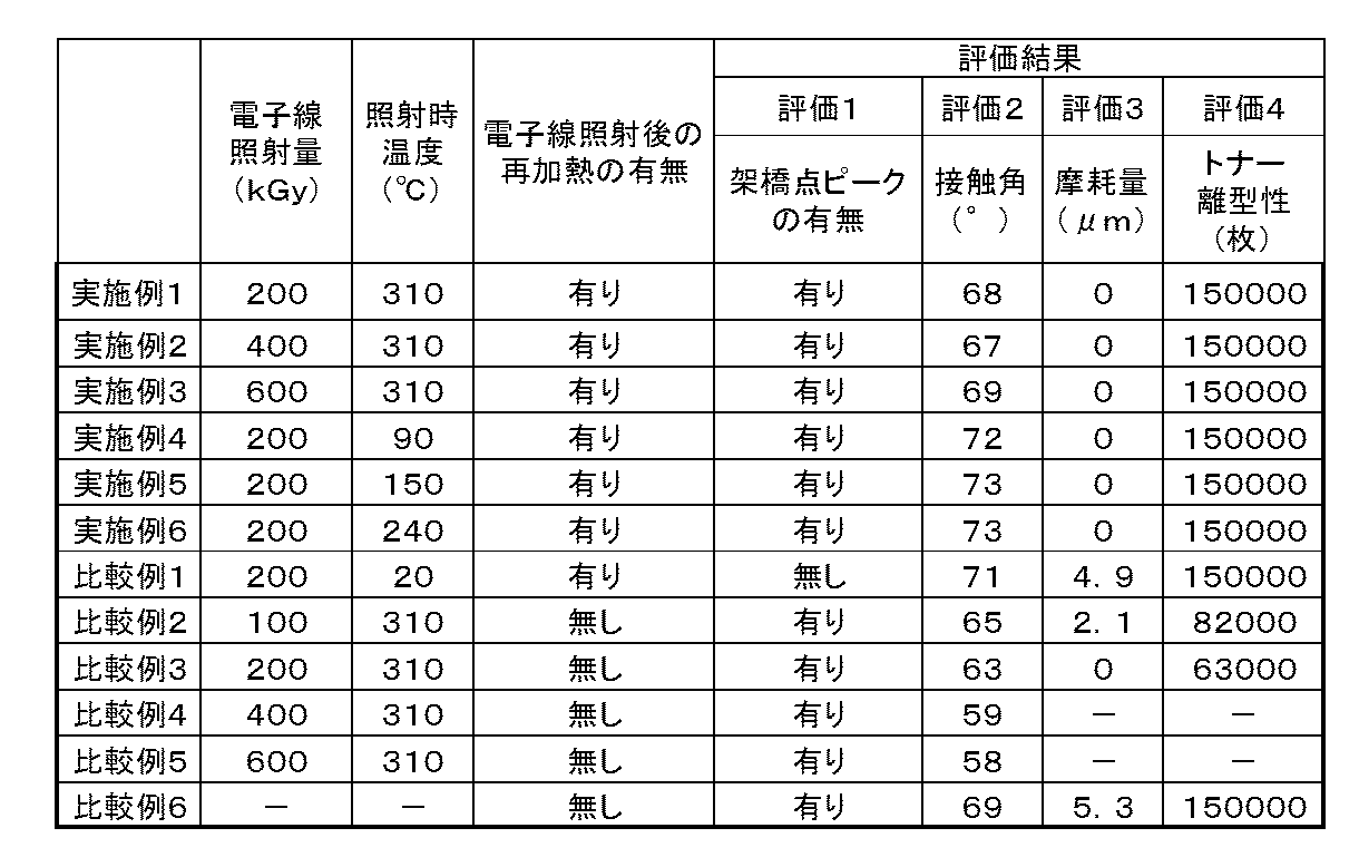
評価2の結果から、電子線照射を行っていない比較例6の接触角に対し、電子線を照射した比較例3~5は、電子線照射量が増えるにつれ、接触角が低下していることがわかる。それに対して、再加熱を行った実施例1~3では接触角の値が再び比較例6の値近くまで回復していることがわかる。
From the result of evaluation 2, it can be seen that as compared with the contact angle of Comparative Example 6 in which no electron beam irradiation was performed, in Comparative Examples 3 to 5 where the electron beam was irradiated, the contact angle decreased as the electron beam irradiation amount increased. I understand. On the other hand, in Examples 1 to 3 in which reheating was performed, it can be seen that the value of the contact angle recovered again to a value close to that of Comparative Example 6.
また、評価3の結果から、実施例1~6については、150000(150K)枚通紙後もほとんど摩耗しておらず、比較例6と比べると、PFAの架橋により表層の耐摩耗性が向上したことが確認できた。
Further, from the results of Evaluation 3, Examples 1 to 6 were hardly worn after passing 150,000 (150K) sheets, and compared with Comparative Example 6, the wear resistance of the surface layer was improved by cross-linking of PFA. I was able to confirm.
さらに、評価4に関して、表1の「トナー離型性(枚)」の欄に示したように、接触角が67°以上ある実施例1~6、比較例1については150000(150K)枚通紙後もトナーのオフセットは確認されなかった。一方、接触角が67°未満である比較例2、3ではそれぞれ、82000(82K)枚目、63000(63K)枚目の電子写真画像にトナーのオフセットが発生した。
また、実施例1、4~6、比較例1を比べると、電子線照射時の未架橋のPFAを含む膜の温度が、未架橋のPFAのガラス転移点である90℃以上であってもPFAに架橋反応が生じており、表層の耐摩耗性が向上していることがわかる。
更に、実施例1、4~6を比べると、電子線照射時の未架橋PFAを含む膜の温度を、未架橋のPFAの融点近傍である310℃とした実施例1より、電子線照射時の未架橋PFAを含む膜の温度が、未架橋のPFAのガラス転移点(Tg)以上、未架橋のPFAの融点より60℃低い温度(Tm-60℃)以下の実施例4~6の方が接触角の値が大きい。すなわち、実施例4~6に係る定着フィルムの表面は、トナー離型性がより向上していると考えられる。未架橋のPFAの融点近傍での架橋では、結晶が溶融して分子鎖の切断、架橋、再配列が起こるため、架橋後のPFAは結晶化度が低下する。それに対し、未架橋のPFAのガラス転移点(Tg)以上、未架橋のPFAの融点より60℃低い温度(Tm-60℃)以下の温度範囲に調整した未架橋PFAの架橋は、結晶部分を維持したまま、柔軟な非晶質部分で分子鎖の切断、架橋、再配列が起こるため、結晶化度が上がり、接触角の値が大きくなったものと考えられる。 Further, regardingevaluation 4, as shown in the column of “toner releasability (sheets)” in Table 1, Examples 1 to 6 having a contact angle of 67 ° or more and Comparative Example 1 have 150,000 (150K) sheets. No toner offset was observed after the paper. On the other hand, in Comparative Examples 2 and 3 where the contact angle was less than 67 °, toner offset occurred in the electrophotographic images of the 82000 (82K) and 63000 (63K) sheets, respectively.
Further, when Examples 1, 4 to 6 and Comparative Example 1 are compared, even when the temperature of the film containing uncrosslinked PFA upon electron beam irradiation is 90 ° C. or higher, which is the glass transition point of uncrosslinked PFA. It can be seen that a cross-linking reaction has occurred in PFA, and the wear resistance of the surface layer is improved.
Further, comparing Examples 1 and 4 to 6, the temperature of the film containing uncrosslinked PFA at the time of electron beam irradiation was 310 ° C., which is near the melting point of uncrosslinked PFA. Examples 4 to 6 in which the temperature of the film containing uncrosslinked PFA is not lower than the glass transition point (Tg) of uncrosslinked PFA and 60 ° C. lower than the melting point of uncrosslinked PFA (Tm-60 ° C.) The contact angle value is large. That is, the surface of the fixing film according to Examples 4 to 6 is considered to have improved toner releasability. In cross-linking in the vicinity of the melting point of uncrosslinked PFA, the crystal melts and molecular chains are broken, cross-linked, and rearranged, so that the crystallinity of PFA after cross-linking decreases. On the other hand, crosslinking of uncrosslinked PFA adjusted to a temperature range between the glass transition point (Tg) of uncrosslinked PFA and 60 ° C. lower than the melting point of uncrosslinked PFA (Tm−60 ° C.) Since the molecular chain is cut, cross-linked, and rearranged in the flexible amorphous portion while maintaining the crystallinity, it is considered that the crystallinity is increased and the value of the contact angle is increased.
また、実施例1、4~6、比較例1を比べると、電子線照射時の未架橋のPFAを含む膜の温度が、未架橋のPFAのガラス転移点である90℃以上であってもPFAに架橋反応が生じており、表層の耐摩耗性が向上していることがわかる。
更に、実施例1、4~6を比べると、電子線照射時の未架橋PFAを含む膜の温度を、未架橋のPFAの融点近傍である310℃とした実施例1より、電子線照射時の未架橋PFAを含む膜の温度が、未架橋のPFAのガラス転移点(Tg)以上、未架橋のPFAの融点より60℃低い温度(Tm-60℃)以下の実施例4~6の方が接触角の値が大きい。すなわち、実施例4~6に係る定着フィルムの表面は、トナー離型性がより向上していると考えられる。未架橋のPFAの融点近傍での架橋では、結晶が溶融して分子鎖の切断、架橋、再配列が起こるため、架橋後のPFAは結晶化度が低下する。それに対し、未架橋のPFAのガラス転移点(Tg)以上、未架橋のPFAの融点より60℃低い温度(Tm-60℃)以下の温度範囲に調整した未架橋PFAの架橋は、結晶部分を維持したまま、柔軟な非晶質部分で分子鎖の切断、架橋、再配列が起こるため、結晶化度が上がり、接触角の値が大きくなったものと考えられる。 Further, regarding
Further, when Examples 1, 4 to 6 and Comparative Example 1 are compared, even when the temperature of the film containing uncrosslinked PFA upon electron beam irradiation is 90 ° C. or higher, which is the glass transition point of uncrosslinked PFA. It can be seen that a cross-linking reaction has occurred in PFA, and the wear resistance of the surface layer is improved.
Further, comparing Examples 1 and 4 to 6, the temperature of the film containing uncrosslinked PFA at the time of electron beam irradiation was 310 ° C., which is near the melting point of uncrosslinked PFA. Examples 4 to 6 in which the temperature of the film containing uncrosslinked PFA is not lower than the glass transition point (Tg) of uncrosslinked PFA and 60 ° C. lower than the melting point of uncrosslinked PFA (Tm-60 ° C.) The contact angle value is large. That is, the surface of the fixing film according to Examples 4 to 6 is considered to have improved toner releasability. In cross-linking in the vicinity of the melting point of uncrosslinked PFA, the crystal melts and molecular chains are broken, cross-linked, and rearranged, so that the crystallinity of PFA after cross-linking decreases. On the other hand, crosslinking of uncrosslinked PFA adjusted to a temperature range between the glass transition point (Tg) of uncrosslinked PFA and 60 ° C. lower than the melting point of uncrosslinked PFA (Tm−60 ° C.) Since the molecular chain is cut, cross-linked, and rearranged in the flexible amorphous portion while maintaining the crystallinity, it is considered that the crystallinity is increased and the value of the contact angle is increased.
これらの結果より、未架橋のPFAへの、酸素不在下、未架橋のPFAのガラス転移点以上、未架橋のPFAの融点近傍までの温度範囲で電子線の照射により、架橋構造を有するPFAが形成され、耐摩耗性が向上したことがわかる。架橋構造は19F-NMRで‐103ppm付近のピークを観測することで確認できる。また、電子線照射により離型性の低下が観測されたが、再加熱することで離型性が回復し、耐摩耗性の向上も保たれたままであった。このとき必要な接触角は、ぬれ張力が31.0mN/mである、ぬれ張力試験用混合液を使用して、67°以上であることがわかった。また、特に離型性が良い条件として、電子線の照射時温度を、未架橋のPFAのガラス転移点(Tg)以上、未架橋のPFAの融点より60℃低い温度(Tm-60℃)以下にすることが好ましいことがわかった。
From these results, PFA having a crosslinked structure is obtained by irradiation with an electron beam in the temperature range from the glass transition point of uncrosslinked PFA to the vicinity of the melting point of uncrosslinked PFA in the absence of oxygen to uncrosslinked PFA. As can be seen, the wear resistance is improved. The crosslinked structure can be confirmed by observing a peak around −103 ppm by 19F-NMR. In addition, although a decrease in releasability was observed due to electron beam irradiation, the releasability was recovered by reheating, and the improvement in wear resistance was maintained. The contact angle required at this time was found to be 67 ° or more using a wet tension test mixed solution having a wet tension of 31.0 mN / m. Further, as a condition with particularly good releasability, the electron beam irradiation temperature is not less than the glass transition point (Tg) of uncrosslinked PFA and not more than 60 ° C. below the melting point of uncrosslinked PFA (Tm-60 ° C.). It turned out to be preferable.
この出願は2012年8月2日に出願された日本国特許出願第2012-172116号及び2013年6月13日に出願された日本国特許出願第2013-124881号からの優先権を主張するものであり、その内容を引用してこの出願の一部とするものである。
This application claims priority from Japanese Patent Application No. 2012-172116 filed on August 2, 2012 and Japanese Patent Application No. 2013-124881 filed on June 13, 2013 The contents of which are incorporated herein by reference.
1:電子写真感光体
2:帯電ローラ
3:レーザービームスキャナ
4:現像装置
5:転写ローラ
6:定着装置
7:クリーニング装置
8:給送ローラ
9:給送カセット
10:ガイド
11:レジストローラ
12:搬送ガイド
13:搬送ローラ
14:ガイド
15:排出ローラ
16:排出トレイ
LB:レーザービーム
TO:トナー
P:記録材 1: Electrophotographic photosensitive member 2: Charging roller 3: Laser beam scanner 4: Developing device 5: Transfer roller 6: Fixing device 7: Cleaning device 8: Feeding roller 9: Feeding cassette 10: Guide 11: Registration roller 12: Conveyance guide 13: Conveyance roller 14: Guide 15: Discharge roller 16: Discharge tray LB: Laser beam TO: Toner P: Recording material
Claims (12)
- 基材、該基材の表面に設けられた弾性層、及び表層を有する定着部材であって、
該表層は、
下記構造式(1)で示される部分構造を有しているテトラフルオロエチレン-パーフルオロアルキルビニルエーテル共重合体を含み、かつ、
ぬれ張力が31.0mN/mであるぬれ張力試験用混合液で測定した接触角が67度以上である表面を有することを特徴とする定着部材:

The surface layer is
A tetrafluoroethylene-perfluoroalkyl vinyl ether copolymer having a partial structure represented by the following structural formula (1), and
A fixing member having a surface having a contact angle of 67 ° or more measured by a wet tension test liquid mixture having a wet tension of 31.0 mN / m:
- 前記表層が、テトラフルオロエチレン-パーフルオロアルキルビニルエーテル共重合体を含む層に対して、酸素不在下で、該テトラフルオロエチレン-パーフルオロアルキルビニルエーテル共重合体の融点近傍で電離性放射線を照射し、その後に、該テトラフルオロエチレン-パーフルオロアルキルビニルエーテル共重合体の融点以上で加熱することによって製造されたものである請求項1に記載の定着部材。 The surface layer is irradiated with ionizing radiation near the melting point of the tetrafluoroethylene-perfluoroalkyl vinyl ether copolymer in the absence of oxygen to the layer containing the tetrafluoroethylene-perfluoroalkyl vinyl ether copolymer, The fixing member according to claim 1, wherein the fixing member is produced by heating at a temperature equal to or higher than a melting point of the tetrafluoroethylene-perfluoroalkyl vinyl ether copolymer.
- 前記弾性層が、シリコーンゴムを含む請求項1または2に記載の定着部材。 The fixing member according to claim 1, wherein the elastic layer includes silicone rubber.
- 前記基材が、ポリイミド、ポリアミドイミドおよびポリエーテルスルホンからなる群から選ばれる少なくとも1つの樹脂を含む請求項1~3のいずれか一項に記載の定着部材。 The fixing member according to any one of claims 1 to 3, wherein the base material includes at least one resin selected from the group consisting of polyimide, polyamideimide, and polyethersulfone.
- 前記基材が、ニッケルまたはステンレスを含む請求項1~3のいずれか一項に記載の定着部材。 The fixing member according to any one of claims 1 to 3, wherein the base material contains nickel or stainless steel.
- 前記基材の厚みが20~60μmである請求項1~5のいずれか一項に記載の定着部材。 The fixing member according to any one of claims 1 to 5, wherein the thickness of the base material is 20 to 60 µm.
- 請求項1~6のいずれか一項に記載の定着部材と、該定着部材の加熱装置と、該定着部材に対向して配置されている加圧部材とを有することを特徴とする定着装置。 A fixing device comprising: the fixing member according to any one of claims 1 to 6, a heating device for the fixing member, and a pressure member disposed to face the fixing member.
- 請求項7に記載の定着装置を具備していることを特徴とする画像形成装置。 An image forming apparatus comprising the fixing device according to claim 7.
- 基材と、
該基材の表面に設けられた弾性層と、
下記構造式(1)で示される部分構造を有しているテトラフルオロエチレン-パーフルオロアルキルビニルエーテル共重合体を含む表層と、を有する定着部材の製造方法であって、
該表層を、下記第一~第三の工程により形成することを特徴とする定着部材の製造方法:
(1)該弾性層の表面に形成した、未架橋のテトラフルオロエチレン-パーフルオロアルキルビニルエーテル共重合体を含む膜の温度を、該テトラフルオロエチレン-パーフルオロアルキルビニルエーテル共重合体のガラス転移点(Tg)以上、該テトラフルオロエチレン-パーフルオロアルキルビニルエーテル共重合体の融点より30℃高い温度(Tm+30℃)以下の温度範囲に調整する第一の工程、
(2)該第一の工程にて調整した温度範囲にある、該テトラフルオロエチレン-パーフルオロアルキルビニルエーテル共重合体を含む膜の表面に、酸素濃度が1000ppm以下の雰囲気下、電離性放射線を照射し、該テトラフルオロエチレン-パーフルオロアルキルビニルエーテル共重合体に、下記構造式(1)で示される部分構造を形成せしめる第二の工程、
(3)該第二の工程によって得られた、下記構造式(1)で示される部分構造を有するテトラフルオロエチレン-パーフルオロアルキルビニルエーテル共重合体を含む膜の温度を、340℃以上380℃以下の温度範囲に調整する第三の工程:

An elastic layer provided on the surface of the substrate;
A surface layer containing a tetrafluoroethylene-perfluoroalkyl vinyl ether copolymer having a partial structure represented by the following structural formula (1), comprising:
A method for producing a fixing member, wherein the surface layer is formed by the following first to third steps:
(1) The temperature of the film containing an uncrosslinked tetrafluoroethylene-perfluoroalkyl vinyl ether copolymer formed on the surface of the elastic layer is changed to the glass transition point of the tetrafluoroethylene-perfluoroalkyl vinyl ether copolymer ( Tg) The first step of adjusting to a temperature range of 30 ° C. higher than the melting point of the tetrafluoroethylene-perfluoroalkyl vinyl ether copolymer (Tm + 30 ° C.) or lower,
(2) Irradiating the surface of the film containing the tetrafluoroethylene-perfluoroalkyl vinyl ether copolymer in the temperature range adjusted in the first step with ionizing radiation in an atmosphere having an oxygen concentration of 1000 ppm or less A second step of forming a partial structure represented by the following structural formula (1) in the tetrafluoroethylene-perfluoroalkyl vinyl ether copolymer,
(3) The temperature of the film containing the tetrafluoroethylene-perfluoroalkyl vinyl ether copolymer having a partial structure represented by the following structural formula (1) obtained by the second step is 340 ° C. or higher and 380 ° C. or lower. Third step of adjusting to the temperature range of:
- 前記第一の工程において、テトラフルオロエチレン-パーフルオロアルキルビニルエーテル共重合体を含む膜の温度を、
該テトラフルオロエチレン-パーフルオロアルキルビニルエーテル共重合体のガラス転移点(Tg)以上、
該テトラフルオロエチレン-パーフルオロアルキルビニルエーテル共重合体の融点より60℃低い温度(Tm-60℃)以下の温度範囲に調整する請求項10に記載の定着部材の製造方法。 In the first step, the temperature of the film containing the tetrafluoroethylene-perfluoroalkyl vinyl ether copolymer is
More than the glass transition point (Tg) of the tetrafluoroethylene-perfluoroalkyl vinyl ether copolymer,
11. The method for producing a fixing member according to claim 10, wherein the temperature is adjusted to a temperature range of 60 ° C. lower than the melting point of the tetrafluoroethylene-perfluoroalkyl vinyl ether copolymer (Tm-60 ° C.) or less. - 前記第三の工程において、前記構造式(1)で示される部分構造を有するテトラフルオロエチレン-パーフルオロアルキルビニルエーテル共重合体を含む膜の温度を340℃以上380℃以下の温度範囲内に5分以上維持する請求項9または10に記載の定着部材の製造方法。 In the third step, the temperature of the film containing the tetrafluoroethylene-perfluoroalkyl vinyl ether copolymer having the partial structure represented by the structural formula (1) is set within a temperature range of 340 ° C. to 380 ° C. for 5 minutes. The method for manufacturing a fixing member according to claim 9 or 10, wherein the fixing member is maintained as described above.
- 前記第三の工程において、前記構造式(1)で示される部分構造を有するテトラフルオロエチレン-パーフルオロアルキルビニルエーテル共重合体を含む膜の温度を340℃以上380℃以下の温度範囲内に維持する時間が、10分以上、20分以下である請求項11に記載の定着部材の製造方法。 In the third step, the temperature of the film containing the tetrafluoroethylene-perfluoroalkyl vinyl ether copolymer having the partial structure represented by the structural formula (1) is maintained within a temperature range of 340 ° C. or higher and 380 ° C. or lower. The method for manufacturing a fixing member according to claim 11, wherein the time is 10 minutes or more and 20 minutes or less.
Priority Applications (3)
| Application Number | Priority Date | Filing Date | Title |
|---|---|---|---|
| CN201380040975.0A CN104718502B (en) | 2012-08-02 | 2013-07-23 | Fixing member, method for producing same, fixing device and image forming device |
| EP13826163.1A EP2881800B1 (en) | 2012-08-02 | 2013-07-23 | Fixing member, method for producing same, fixing device and image forming device |
| US14/104,765 US9465338B2 (en) | 2012-08-02 | 2013-12-12 | Fixing member, method for manufacturing the same, fixing apparatus, and image forming apparatus |
Applications Claiming Priority (4)
| Application Number | Priority Date | Filing Date | Title |
|---|---|---|---|
| JP2012172116 | 2012-08-02 | ||
| JP2012-172116 | 2012-08-02 | ||
| JP2013-124881 | 2013-06-13 | ||
| JP2013124881A JP6425371B2 (en) | 2012-08-02 | 2013-06-13 | Fixing member and manufacturing method thereof, fixing device, image forming apparatus |
Related Child Applications (1)
| Application Number | Title | Priority Date | Filing Date |
|---|---|---|---|
| US14/104,765 Continuation US9465338B2 (en) | 2012-08-02 | 2013-12-12 | Fixing member, method for manufacturing the same, fixing apparatus, and image forming apparatus |
Publications (1)
| Publication Number | Publication Date |
|---|---|
| WO2014020861A1 true WO2014020861A1 (en) | 2014-02-06 |
Family
ID=50027570
Family Applications (1)
| Application Number | Title | Priority Date | Filing Date |
|---|---|---|---|
| PCT/JP2013/004481 WO2014020861A1 (en) | 2012-08-02 | 2013-07-23 | Fixing member, method for producing same, fixing device and image forming device |
Country Status (5)
| Country | Link |
|---|---|
| US (1) | US9465338B2 (en) |
| EP (1) | EP2881800B1 (en) |
| JP (1) | JP6425371B2 (en) |
| CN (1) | CN104718502B (en) |
| WO (1) | WO2014020861A1 (en) |
Families Citing this family (17)
| Publication number | Priority date | Publication date | Assignee | Title |
|---|---|---|---|---|
| JP6177055B2 (en) | 2012-10-29 | 2017-08-09 | キヤノン株式会社 | Coating apparatus, coating method, fixing member manufacturing apparatus, fixing member manufacturing method |
| JP6041623B2 (en) | 2012-10-29 | 2016-12-14 | キヤノン株式会社 | Fixing member and manufacturing method thereof |
| WO2015118810A1 (en) | 2014-02-05 | 2015-08-13 | キヤノン株式会社 | Fixing member and method for manufacturing same, fixing device, and image formation device |
| JP6347727B2 (en) | 2014-11-17 | 2018-06-27 | キヤノン株式会社 | Fixing member, fixing device, and image forming apparatus |
| US9715202B2 (en) * | 2015-10-06 | 2017-07-25 | Canon Kabushiki Kaisha | Fixing member, fixing apparatus, image forming apparatus, and method of producing fixing member |
| US10243604B2 (en) | 2015-12-08 | 2019-03-26 | Uber Technologies, Inc. | Autonomous vehicle mesh networking configuration |
| US9432929B1 (en) | 2015-12-08 | 2016-08-30 | Uber Technologies, Inc. | Communication configuration system for a fleet of automated vehicles |
| US9902311B2 (en) | 2016-02-22 | 2018-02-27 | Uber Technologies, Inc. | Lighting device for a vehicle |
| US9891565B1 (en) * | 2016-07-28 | 2018-02-13 | Canon Kabushiki Kaisha | Fixing member, fixing apparatus and electrophotographic image forming apparatus |
| JP7001384B2 (en) * | 2016-08-10 | 2022-01-19 | キヤノン株式会社 | How to manufacture an electrophotographic belt |
| JP6369511B2 (en) | 2016-08-30 | 2018-08-08 | ダイキン工業株式会社 | Method for producing modified molded product, molded product, diaphragm and diaphragm valve |
| US10293818B2 (en) | 2017-03-07 | 2019-05-21 | Uber Technologies, Inc. | Teleassistance data prioritization for self-driving vehicles |
| US10202126B2 (en) | 2017-03-07 | 2019-02-12 | Uber Technologies, Inc. | Teleassistance data encoding for self-driving vehicles |
| JP6957169B2 (en) * | 2017-03-07 | 2021-11-02 | キヤノン株式会社 | Manufacturing method of rotating body for electrophotographic, fixing device, electrophotographic image forming device and rotating body |
| JP7098388B2 (en) | 2017-04-28 | 2022-07-11 | キヤノン株式会社 | Method for manufacturing liquid silicone rubber mixture and electrophotographic member |
| US10809654B2 (en) | 2018-08-28 | 2020-10-20 | Canon Kabushiki Kaisha | Pressure roller for fixing apparatus, fixing apparatus and image forming apparatus |
| US11830302B2 (en) | 2020-03-24 | 2023-11-28 | Uatc, Llc | Computer system for utilizing ultrasonic signals to implement operations for autonomous vehicles |
Citations (10)
| Publication number | Priority date | Publication date | Assignee | Title |
|---|---|---|---|---|
| JPH06250553A (en) * | 1993-02-22 | 1994-09-09 | Kin Yosha Kk | Roll |
| JP2000194220A (en) * | 1998-12-28 | 2000-07-14 | Canon Inc | Fixing device |
| JP2002023539A (en) * | 2000-07-11 | 2002-01-23 | Fuji Xerox Co Ltd | Fixing member, method for manufacturing fixing member and fixing device |
| JP2004315833A (en) * | 2004-08-25 | 2004-11-11 | Hitachi Cable Ltd | Modified fluorocarbon resin molded item |
| JP2007047641A (en) * | 2005-08-12 | 2007-02-22 | Ricoh Printing Systems Ltd | Fixing member and fixing unit using same |
| JP2010176130A (en) * | 2009-01-29 | 2010-08-12 | Xerox Corp | Fuser member and method for manufacturing the same |
| JP2010181621A (en) | 2009-02-05 | 2010-08-19 | Sumitomo Electric Fine Polymer Inc | Non-rotary pressure member having cross-linked fluororesin layer and method for manufacturing the same |
| JP2011158892A (en) * | 2010-01-05 | 2011-08-18 | Canon Inc | Fixing member, method of manufacturing the same and fixing device |
| JP2012058644A (en) * | 2010-09-13 | 2012-03-22 | Ricoh Co Ltd | Method for manufacturing endless metallic thin film |
| JP2012118371A (en) * | 2010-12-02 | 2012-06-21 | Konica Minolta Business Technologies Inc | Heat pressure fixing method and image forming apparatus |
Family Cites Families (11)
| Publication number | Priority date | Publication date | Assignee | Title |
|---|---|---|---|---|
| JP2003140494A (en) * | 2001-11-05 | 2003-05-14 | Hitachi Ltd | Fixing roll and fixing device |
| JP2003156961A (en) * | 2001-11-22 | 2003-05-30 | Fuji Xerox Co Ltd | Rotating body for fixing, rotating body for pressurizing, rotating body for transferring, rotating body for electrifying and rotating body for simultaneous transferring and fixing |
| JP4407708B2 (en) * | 2007-03-05 | 2010-02-03 | 日立電線株式会社 | Coat material |
| JP2010196130A (en) * | 2009-02-26 | 2010-09-09 | Sumitomo Wiring Syst Ltd | Method and apparatus for modifying steel surface |
| JP6202918B2 (en) | 2012-07-27 | 2017-09-27 | キヤノン株式会社 | Electrophotographic member, method for producing electrophotographic member, fixing device, and electrophotographic image forming apparatus |
| JP6041623B2 (en) | 2012-10-29 | 2016-12-14 | キヤノン株式会社 | Fixing member and manufacturing method thereof |
| JP6214300B2 (en) | 2012-10-29 | 2017-10-18 | キヤノン株式会社 | Method and apparatus for manufacturing fixing member |
| JP6223089B2 (en) | 2012-10-29 | 2017-11-01 | キヤノン株式会社 | Method and apparatus for manufacturing fixing member |
| JP6238662B2 (en) | 2012-10-29 | 2017-11-29 | キヤノン株式会社 | Method and apparatus for manufacturing fixing member |
| JP6177055B2 (en) | 2012-10-29 | 2017-08-09 | キヤノン株式会社 | Coating apparatus, coating method, fixing member manufacturing apparatus, fixing member manufacturing method |
| JP2014089255A (en) | 2012-10-29 | 2014-05-15 | Canon Inc | Method for manufacturing fixing member |
-
2013
- 2013-06-13 JP JP2013124881A patent/JP6425371B2/en active Active
- 2013-07-23 WO PCT/JP2013/004481 patent/WO2014020861A1/en active Application Filing
- 2013-07-23 CN CN201380040975.0A patent/CN104718502B/en active Active
- 2013-07-23 EP EP13826163.1A patent/EP2881800B1/en active Active
- 2013-12-12 US US14/104,765 patent/US9465338B2/en active Active
Patent Citations (10)
| Publication number | Priority date | Publication date | Assignee | Title |
|---|---|---|---|---|
| JPH06250553A (en) * | 1993-02-22 | 1994-09-09 | Kin Yosha Kk | Roll |
| JP2000194220A (en) * | 1998-12-28 | 2000-07-14 | Canon Inc | Fixing device |
| JP2002023539A (en) * | 2000-07-11 | 2002-01-23 | Fuji Xerox Co Ltd | Fixing member, method for manufacturing fixing member and fixing device |
| JP2004315833A (en) * | 2004-08-25 | 2004-11-11 | Hitachi Cable Ltd | Modified fluorocarbon resin molded item |
| JP2007047641A (en) * | 2005-08-12 | 2007-02-22 | Ricoh Printing Systems Ltd | Fixing member and fixing unit using same |
| JP2010176130A (en) * | 2009-01-29 | 2010-08-12 | Xerox Corp | Fuser member and method for manufacturing the same |
| JP2010181621A (en) | 2009-02-05 | 2010-08-19 | Sumitomo Electric Fine Polymer Inc | Non-rotary pressure member having cross-linked fluororesin layer and method for manufacturing the same |
| JP2011158892A (en) * | 2010-01-05 | 2011-08-18 | Canon Inc | Fixing member, method of manufacturing the same and fixing device |
| JP2012058644A (en) * | 2010-09-13 | 2012-03-22 | Ricoh Co Ltd | Method for manufacturing endless metallic thin film |
| JP2012118371A (en) * | 2010-12-02 | 2012-06-21 | Konica Minolta Business Technologies Inc | Heat pressure fixing method and image forming apparatus |
Also Published As
| Publication number | Publication date |
|---|---|
| EP2881800B1 (en) | 2020-06-24 |
| EP2881800A4 (en) | 2016-06-15 |
| CN104718502B (en) | 2017-02-01 |
| US20140107250A1 (en) | 2014-04-17 |
| CN104718502A (en) | 2015-06-17 |
| US9465338B2 (en) | 2016-10-11 |
| JP2014044401A (en) | 2014-03-13 |
| EP2881800A1 (en) | 2015-06-10 |
| JP6425371B2 (en) | 2018-11-21 |
Similar Documents
| Publication | Publication Date | Title |
|---|---|---|
| WO2014020861A1 (en) | Fixing member, method for producing same, fixing device and image forming device | |
| JP6173040B2 (en) | Fixing belt and fixing device | |
| EP3086183B1 (en) | Member for electrophotography, fixing device and electrophotographic image-forming apparatus | |
| JP6433320B2 (en) | Fixing member, manufacturing method thereof, fixing device, and image forming apparatus | |
| CN107728451B (en) | Electrophotographic member, fixing device, and method for manufacturing electrophotographic belt | |
| CN110297416B (en) | Fixing member, fixing device, and electrophotographic image forming apparatus | |
| US9715202B2 (en) | Fixing member, fixing apparatus, image forming apparatus, and method of producing fixing member | |
| CN110955134A (en) | Fixing belt, fixing device, process cartridge, image forming apparatus, and base material for fixing belt | |
| US8805257B2 (en) | Applying device, fixing device, and image forming apparatus | |
| CN115407632A (en) | Fixing belt, fixing device and image forming apparatus | |
| US20170261894A1 (en) | Fixing member, fixing device, and image forming apparatus | |
| JP2019174590A (en) | Fixing member, fixing device, process cartridge, and image forming apparatus | |
| JP7206746B2 (en) | Fixing member, fixing device, process cartridge, and image forming apparatus | |
| JP2016142993A (en) | Fixing member, fixing device, and image forming apparatus | |
| CN115437229A (en) | Belt, fixing device and image forming apparatus | |
| JP2020106561A (en) | Fixing member, heat fixing device, and manufacturing method of fixing member | |
| JP2012194281A (en) | Component for image forming apparatus, fixing device, and image forming apparatus | |
| WO2020096707A1 (en) | Fixing device comprising nip plate treated with electron beam injected fluorinated resins | |
| JP2019219557A (en) | Fixing device and method for manufacturing fixing device | |
| JP2018036466A (en) | Fixing member and fixing device using the same, and method for producing fixing member |
Legal Events
| Date | Code | Title | Description |
|---|---|---|---|
| 121 | Ep: the epo has been informed by wipo that ep was designated in this application |
Ref document number: 13826163 Country of ref document: EP Kind code of ref document: A1 |
|
| WWE | Wipo information: entry into national phase |
Ref document number: 2013826163 Country of ref document: EP |
|
| NENP | Non-entry into the national phase |
Ref country code: DE |