WO2014020752A1 - サーバ計算機及びサーバ計算方法 - Google Patents
サーバ計算機及びサーバ計算方法 Download PDFInfo
- Publication number
- WO2014020752A1 WO2014020752A1 PCT/JP2012/069788 JP2012069788W WO2014020752A1 WO 2014020752 A1 WO2014020752 A1 WO 2014020752A1 JP 2012069788 W JP2012069788 W JP 2012069788W WO 2014020752 A1 WO2014020752 A1 WO 2014020752A1
- Authority
- WO
- WIPO (PCT)
- Prior art keywords
- priority
- unit
- processing
- server
- operation state
- Prior art date
- Legal status (The legal status is an assumption and is not a legal conclusion. Google has not performed a legal analysis and makes no representation as to the accuracy of the status listed.)
- Ceased
Links
Images




Classifications
-
- G—PHYSICS
- G06—COMPUTING OR CALCULATING; COUNTING
- G06F—ELECTRIC DIGITAL DATA PROCESSING
- G06F9/00—Arrangements for program control, e.g. control units
- G06F9/06—Arrangements for program control, e.g. control units using stored programs, i.e. using an internal store of processing equipment to receive or retain programs
- G06F9/46—Multiprogramming arrangements
- G06F9/48—Program initiating; Program switching, e.g. by interrupt
-
- G—PHYSICS
- G06—COMPUTING OR CALCULATING; COUNTING
- G06F—ELECTRIC DIGITAL DATA PROCESSING
- G06F9/00—Arrangements for program control, e.g. control units
- G06F9/06—Arrangements for program control, e.g. control units using stored programs, i.e. using an internal store of processing equipment to receive or retain programs
- G06F9/44—Arrangements for executing specific programs
- G06F9/455—Emulation; Interpretation; Software simulation, e.g. virtualisation or emulation of application or operating system execution engines
- G06F9/45533—Hypervisors; Virtual machine monitors
- G06F9/45558—Hypervisor-specific management and integration aspects
- G06F2009/4557—Distribution of virtual machine instances; Migration and load balancing
Definitions
- the present invention relates to a server computer and a server calculation method for scheduling a virtual computer according to the operation status of the virtual computer in order to maintain the real-time property of the virtualized server computer (virtual computer).
- Server virtualization technology has the advantage of reducing operating costs and computer installation space by executing multiple virtual machines (VMs) on one physical computer and reducing the number of physical computers. Have been bathed. However, in the control system, the application process in the VM is required to be real time.
- VMs virtual machines
- Patent Document 1 is a content for controlling the execution order and the execution timing between processes straddling VMs, for example, between the main process of VM1 and the subprocess of VM2.
- the main process is a method realized by explicitly requesting the next process to be executed in the process and requesting the execution contents.
- the execution order between all processes must be determined in advance.
- no consideration is given to ensuring real-time performance of a process group that requires a deadline.
- Patent Document 1 In the conventional virtualization platform such as Patent Document 1, it is possible to control the execution order and execution timing between processes across VMs. However, it is difficult to ensure the real-time property of the process group in the VM.
- VMs virtual machines
- a hardware resource CPU, Since memory, a disk, a network device, etc.
- CPU Since memory, a disk, a network device, etc.
- Real-time property means that processing of a process group is completed within a deadline.
- One embodiment for solving the problem includes a notification receiving unit that receives notification messages from a plurality of VMs, a performance requirement management storage unit that stores process priorities corresponding to processing states of a plurality of processes, and A process priority management processing unit for determining a process priority corresponding to a process included in the notification message, an operation state management storage unit for storing a process priority corresponding to the process, and a process priority among the stored processes. And a scheduler unit that executes process processing having the highest degree.
- the real-time property of the VM can be ensured.
- Server computer software configuration Server computer hardware configuration (configuration with multi-core CPU and SMP memory). Flow of overall processing of guest (VM). The time chart of the process of the whole server of the conventional problem. Flow of processing of resource allocation setting unit. Resource allocation management table. Flow of dynamic change processing of priority for VM (execution from notification transmission unit to VM operation state management processing unit). Informational message. VM operation state management table (at the time of simultaneous startup). Process flow of the process priority management processing unit. VM performance requirement management table. VM operation state management table (when VM2 is initialized after restarting). Is a time chart of the processing of the entire server after solving the problem. VM operation state management table (when VM2 and VM3 are memory dumped).
- FIG. 1 is a block diagram showing a software configuration of a server computer 100 to which the first embodiment is applied.
- the software configuration of the server computer includes a host 105, VM1 (120), VM2 (130), and VM3 (140).
- the host 105 includes a host OS 101 and a Hyper Mediator 111.
- the host OS (OS: operating system) 101 includes a scheduler unit 102, a resource control mechanism unit 103, and a virtualization mechanism unit 104.
- the scheduler unit 102 is a mechanism for controlling and managing a plurality of processes according to priority.
- VMs 1 to 3 120, 130, 140 are also treated as processes by the host OS.
- the resource control mechanism unit 103 controls computer resources such as a CPU processor, a network device, and a hard disk device for each process.
- the virtualization mechanism unit 104 virtualizes computer resources such as arithmetic devices such as CPUs of real hardware, memory devices, and input / output devices, and executes a plurality of virtual machines (VMs) on one physical computer. It is.
- the virtualization mechanism unit 104 manages the start / execution / stop / pause / restart of the virtual machine (VM), and by executing the virtual machine in a time-sharing manner, a plurality of virtual machines are executed simultaneously. Provide an environment that feels like it is.
- VM virtual machine
- the Hyper Mediator 111 is arranged on the host OS 105 and plays a role of managing the entire VM in cooperation with the VM1 (120), the VM2 (130), and the VM3 (140).
- the Hyper-Mediator 111 includes a notification receiving unit 112, a VM operation state management table 113, a VM performance requirement management table 114, a resource allocation management table 115, a VM operation state management processing unit 116, a process priority management processing unit 117, and a resource allocation setting unit 118. Is provided.
- the VM 1 (120) includes a guest OS 121, a notification transmission unit 122, a startup processing unit 123, an initialization processing unit 124, a control application processing unit 125, and other processes 126 to 129 and other processes 126 to 129.
- the VM2 (130) and the VM3 (140) have the same functional configuration as the VM1 (120).
- the process priority is set to real-time high priority when the process is a control application process as online, and the process of starting up, initializing, and deactivating the process as offline is real-time medium priority or low priority
- memory dump processing when the process is offline is set as normal priority.
- the VM control may be realized by changing the process priority of the VM itself as a method of controlling the VM according to the priority.
- the VM itself may be operated slowly, that is, it may be controlled repeatedly by pausing and resuming.
- the operation state of each VM is notified from the VM to the VM management unit of the host at the time of the state change.
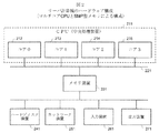
- the server computer 100 configured with the above functions includes, for example, a CPU 211, a memory device 231, a hard disk device 241 for auxiliary storage, an input device 261 such as a keyboard and a mouse, and a liquid crystal as shown in FIG. It can be realized by a general computer including an output device 271 such as a display and a network device 251 for performing data communication with an external device.
- the CPU 211 is an arithmetic unit having a plurality of processor cores 212 to 215.
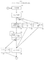
- FIG. 3 is a flowchart showing the overall processing flow of the VMs 1 to 3 (120, 130, 140).
- the VMs 1 to 3 (120, 130, 140) start operating as virtual machines (VMs) when the VM is started 310 by the virtualization mechanism unit 104.
- the startup processing unit inside the VM executes startup processing.
- the process proceeds to step 124, step 128, or step 129.
- the process proceeds to step 124, and the initialization processing unit 124 executes the initialization process.
- the initialization processing unit 124 starts and executes shared memory initialization and control application processing process group startup.
- the control application processing unit executes. Since the control application process is assumed to be a process for control purposes, step 125 is periodically and repeatedly executed. The control application process is periodically executed through the above steps. This control cycle is 1 second in the example of the railway operation management system.
- step 126 when a fall process is requested from the virtualization mechanism unit 104 in step 125, the process proceeds to step 126.
- step 126 when the shutdown is notified from the guest OS 121, the startup processing unit executes the shutdown process and stops.
- the process proceeds to step 127.
- step 127 the contents in the memory, that is, the memory image of the entire VM is stored in the hard disk device so that the failure can be analyzed for the abnormality.
- the backup processing unit 128 performs backup of the entire VM.
- the software replacement processing unit 129 executes software replacement processing in the VM. Steps 128 and 129 then move to step 126, where the start-up processing unit executes the lowering process and stops.
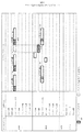
- FIG. 4 is a time chart showing the processing contents of the VMs 1 to 3 and the host.
- VM1 shows a state in which the control application process (step 125 in FIG. 3) is periodically executed (one-second cycle).
- the control application process includes a process 401 for accessing the memory device.
- VM 2 executes the control application process (step 125 in FIG. 3)
- a fall process is requested, the rise process part performs the fall process and the launch process, and the initialization process part performs the initialization process. It is a state to execute.
- the initialization process performed by the VM2 will occupy (410) by accessing the memory device of FIG.
- FIG. 4 is a case where FIGS. 5 and 6 described later are applied. In the case where this is not applied, the real-time property is further disturbed.
- FIG. 5 is a flowchart showing a processing flow of the resource allocation setting unit 118 of FIG.
- the resource allocation setting unit 118 reads the contents stored in the resource allocation management table 115 stored in advance (step 510).
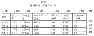
- FIG. 6 is a diagram showing the configuration of the resource allocation management table 115.
- the resource allocation management table 115 is a table stored in advance in order to occupy and allocate computer resources to the host or VM.
- the resource allocation management table 115 includes a type 601 field, a CPU core 602 field, a memory capacity 603 field, a hard disk capacity 604 field, a disk bandwidth 605 field, a network 606 field, and a network bandwidth 607 field.
- the type 601 column one of the host 105, VM1 (120), VM2 (130), and VM3 (140) in FIG. 1 is designated.
- the column of CPU core 602 In the column of CPU core 602, one of cores 0 to 3 (212 to 215) assigned to occupancy is designated in FIG.
- the column of the memory capacity 603 specifies the distribution of the total capacity of the memory device 231 in FIG.
- the column of hard disk capacity 604 designates the distribution of the total capacity of the hard disk device 241 in FIG.
- the column of the disk bandwidth 605 specifies the bandwidth allocation for the maximum hard disk access.
- the column of the network 606 designates the network device name of the network device 251 in FIG.
- the network bandwidth 607 column specifies the bandwidth allocation of the maximum network access. As an example of computer resources, it is assumed that the number of cores is 4, the memory is 1 GB, the hard disk capacity is 20 GB, and the network board is one.
- the first line 610 allocates core 0 to the host, sets the memory capacity to a maximum of 256 MB, the hard disk capacity to a maximum of 10 GB, the disk bandwidth to a maximum of 40%, the network device name to ETH0, and the network bandwidth to a maximum of 10%. It is specified.
- the second line 620 to the fourth line 640 have almost the same contents as the first line 610.
- the resource allocation setting unit 118 grammatically checks the correctness of the setting contents of the resource allocation management table 115 (step 520). If it is not correct, a grammatical error is displayed.
- the resource control mechanism unit 103 is executed according to the setting contents of the resource allocation management table 115 acquired from the resource allocation setting unit 118 (step 530).
- the virtualization mechanism unit 104 acquires all the setting contents and executes the VM (step 530).
- the host and the VM1 to VM3 occupy the computer resources to be used according to the setting contents of the resource allocation management table 115, and the influence and interference between the host and each VM can be reduced to some extent.
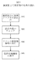
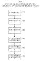
- FIG. 7 is a flowchart showing a flow of dynamic priority change processing for a VM.
- the VMs 120 to 140 execute one of the processes (123 to 129 in FIG. 3) (step 710).
- the notification transmission unit 122 of the VMs 120 to 140 transmits a notification message 150 as a result of each process to the host 105 (step 720).
- the notification receiving unit 112 receives notification messages from a plurality of VMs.
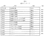
- FIG. 8 is a diagram showing the configuration of the notification message 150.
- the notification message 150 includes a guest name 801 field, a processing status 802 field, and a section 803 field.
- the column of guest name 801 is the contents of any of VM1 to VM3 (120, 130, 140) in FIG.
- the column of the processing state 802 is the contents of any of the processing 123 to 129 in FIG.
- the column of the section 803 is the content of “start” when any of the processes 123 to 129 of FIG. 3 is the start time, and the content of “end” when the time is the end.
- the first line 810 shows the message contents to be notified when the VM1 start-up process is started.
- the guest name 801 is VM1, the process state 802 is the start-up process, and the section 803 is start.
- the contents after the second line are the same as those of the first line 810.
- the notification receiving unit 112 of the host 105 receives the notification message 150 transmitted from the notification transmitting unit 122 (step 730).
- the VM operation state management processing unit 116 executes process processing based on the notification message (step 740).
- the VM operation state management processing unit 116 updates the VM operation state management table 113 according to the content of the notification message 150 (step 750). That is, the VM operation state management processing unit 116 stores the process priority corresponding to the process of the notification message. If the priority 903 of the VM is higher than that of other VMs according to the contents of the updated VM operation state management table 113, the VM executes process processing (step 760). When there are a plurality of high-priority VMs, the VMs are equally executed by time division.
- FIG. 9 is a diagram showing a configuration of the VM operation state management table 113.
- the VM operation state management table 113 includes a guest name 901 column, a processing state 902 column, and a VM process priority 903 column.
- the guest name 901 column contains the contents of any of VM1 to VM3 (120, 130, 140) in FIG.
- the column of the processing state 902 is the content of any of the processing 123 to 129 in FIG.
- the VM process priority 903 column manages the contents of the priority of the VM process activated by the virtualization mechanism unit 104.
- the first line 910 is the content in which the VM 1 manages the state after starting the control application process, the guest name 901 is VM 1, the process state 902 is the control application process, and the VM process priority 903 is 70. . That is, when the contents of 830 in FIG. 8 are received as the notification message 150, the VM operation state management processing unit updates the contents of the first line 910 (step 750). The contents after the second line are almost the same as those of the first line 910.
- the VM process priority 903 is determined in advance in the VM performance requirement management table 114 by a user input (described later in step 1030 of FIG. 10 described later).
- the processing state 902 column of the VM operation state management table 113 in FIG. 9 is updated to the latest state, and the operation state of each VM can be managed on the host.
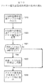
- FIG. 10 is a flowchart showing a process flow of the process priority management processing unit 117.
- Step 1010 reads the contents of the VM performance requirement management table 114. That is, the process priority management processing unit 117 determines the process priority corresponding to the process included in the received notification message.
- FIG. 11 is a diagram showing the configuration of the VM performance requirement management table 114.
- the VM performance requirement management table 114 includes a processing status 1101 column, a performance requirement 1102 column, a process type 1103 column, and a process priority 1104 column.
- the column of the processing state 1101 is the contents of the processing 123 to 129 in FIG.
- the column of the performance requirement 1102 indicates any of HRT (high real-time property), MRT (medium real-time property), LRT (low real-time property), and NRT (non-real time property).
- the column of the process type 1103 has either real time or normal contents. Real time means a real time process, and normal means a normal process.
- the column of the process priority 1104 is a value within the range defined by the OS, for example, a value of 0 to 100 as the process priority value.
- the process priority value means that a larger numerical value is given priority.
- the performance requirement is LRT (low real-time property)
- the process type is real-time process
- the process priority is 30.
- the third line 1130 is a setting that gives priority to other lines, which means that the control application process in the VM has the highest priority.
- FIG. 11 may be created for each VM, in this example, the content is common to each VM. That is, the VM performance requirement management table 114 stores process priorities corresponding to the processing states of a plurality of processes.
- the process priority management processing unit changes the process priority 903 of the VM operation state management table 113 with reference to the process priority 1104 of FIG. 11 (step 1020).
- the process priority management processing unit gives priority to the process with the higher process priority.
- the process proceeds to step 1022 (step 1021).
- the process priority management processing unit suspends and restarts the VM with the lower priority that has changed the process priority 903 (step 1022).
- the process priority management processing unit can temporarily stop and restart the process by issuing an instruction to the virtualization mechanism unit 104.
- the process priority management processing unit instructs the scheduler unit 102 on the process processing order for the part changed in the VM operation state management table 113 (step 1030). That is, the scheduler unit 102 executes a process process having the highest process priority among the processes stored in the VM operation state management table 113.
- the scheduler unit 102 determines that the priority corresponding to the process included in the notification message stored in the VM operation state management storage unit 113 is a process being processed. If the priority is lower than the priority of the process, the process being processed is stopped and the newly received process is executed. If the priority is lower than the priority of the process being processed, the process being processed is continued.
- the scheduler unit 102 finishes executing the process of the high priority process, the process having the next highest priority among the processes stored in the VM operation state management storage unit 113 is executed and given priority. Repeat in descending order.
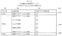
- ⁇ VM operation state management table (when VM2 is initialized after restarting)> 12 shows that when VM2 in FIG. 4 changes the control application process ⁇ the fall process ⁇ the startup process ⁇ the initialization process ⁇ the control application process and the process state 902 in the second row 1220 and the VM The content change in the column of process priority 903 is shown.
- the second row 1220 is realized by performing the processing of FIGS. 7 and 10.
- the meaning of the second line 1220 means that when the VM2 is initially processing the control application process, the VM process priority of 70 changes from 70 ⁇ 30 ⁇ 30 ⁇ 50 ⁇ 70. .
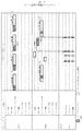
- FIG. 13 is a time chart diagram obtained by improving the time chart of FIG. 4 according to the contents of the present embodiment described above.
- the VM process priority of VM2 is set to 50 (second line 1220 in FIG. 12), so that VM1 is prioritized and processed by VM2 in steps 1021 to 1030 in FIG. . That is, the control application process 1310 of VM1 has priority over the initialization process 1320 of VM2. Therefore, the control application process 1310 of the VM1 can complete the process within the deadline by minimizing the influence by the initialization process 1320 of the VM2. That is, the real-time property of the control application process can be ensured.
- FIG. 14 shows that when VM2 and VM3 change the control application process ⁇ memory dump process ⁇ startup process ⁇ initialization process ⁇ control application process and the process state 902 in the second row 1420 and the VM process
- the change in the contents of the column of the priority 903 is shown, and the change of the contents of the column of the processing state 902 in the third row 1430 and the column of the VM process priority 903 are shown.
- the memory dump processing of VM2 and VM3 involves access to the memory device 231 and access to the hard disk device 241, and affects VM1 during control application processing. Also in such a case of FIG. 12, by setting the priority of VM2 and VM3 to 10, real-time property of the control application process of VM1 can be ensured.
- Server computer 101 Host OS 102: Scheduler unit 103: Resource control mechanism unit 104: Virtualization mechanism unit 105: Host 111: Hyper Mediator 112: Notification receiving unit 113: VM operation state management table 114: VM performance requirement management table 115: Resource allocation management table 116: VM operation state management processing unit 117: Process priority management processing unit 118: Resource allocation setting unit 120: VM1 121: Guest OS 122: Notification transmission unit 123: Startup processing unit 124: Initialization processing unit 125: Control application processing unit 130: VM2 140: VM3
Landscapes
- Engineering & Computer Science (AREA)
- Software Systems (AREA)
- Theoretical Computer Science (AREA)
- Physics & Mathematics (AREA)
- General Engineering & Computer Science (AREA)
- General Physics & Mathematics (AREA)
- Debugging And Monitoring (AREA)
Description
本発明は、仮想化されたサーバ計算機(仮想計算機)のリアルタイム性を維持するために、仮想計算機の動作状況に応じて仮想計算機をスケジュールするサーバ計算機及びサーバ計算方法に関する。
サーバ仮想化技術は、1台の物理計算機上で複数の仮想計算機(VM)を実行し、物理計算機の台数を削減することで、運用コストの低減や計算機設置スペースを軽減できる利点があり、注目を浴びている。ただし、制御システムにおいては、VM内のアプリケーションプロセスはリアルタイム性が要求される。
特許文献1は、VM間を跨ぐプロセス間、例えばVM1のメインプロセスとVM2のサブプロセス間の実行順序や実行タイミングを制御する内容である。メインプロセスはプロセス内で明示的に次実行すべきプロセス指定や実行内容の要求を出すことで実現する方法である。しかし、事前に、全てのプロセス間の実行順序を決めておく必要がある。また、デッドラインの要求されるプロセス群のリアルタイム性の確保に関しては考慮されていない。
特許文献1のような従来の仮想化基盤では、VM間を跨ぐプロセス間の実行順序や実行タイミングを制御することができる。しかし、VM内のプロセス群のリアルタイム性の確保が困難である。
具体的には、仮想化基盤を制御用途のサーバに適用する場合において、1台の物理サーバ計算機上に複数の仮想計算機(VM)を集約する際には、各VMがハードウェア資源(CPU、メモリ、ディスク、ネットワークデバイスなど)を共有するのでVM間の影響が発生し、リアルタイム性を確保することが困難となる。リアルタイム性とは、デッドライン以内にプロセス群の処理を終えることである。
例えば、VMをオンラインで実行中、つまり実際の制御を処理中に、他のVMを保守のために停止および再起動すると、オンライン実行中のVMが影響を受けてリアルタイム性を確保困難となる。
課題を解決するための一つの実施形態は、複数のVMから通知メッセージを受信する通知受信部と、複数のプロセスの処理状態に対応するプロセス優先度を記憶する性能要件管理記憶部と、受信した前記通知メッセージに含まれるプロセスに対応するプロセス優先度を決定するプロセス優先度管理処置部と、プロセスに対応するプロセス優先度を記憶する動作状態管理記憶部と、記憶されたプロセスのうち、プロセス優先度が最も高いプロセス処理を実行するスケジューラ部とを有する。
本発明によれば、VMのリアルタイム性を確保することができる。
本発明の実施の形態について図面を参照して説明する。
以下、第1の実施形態について説明する。第1の実施形態では、制御用途のサーバ計算機に本発明の仮想化基盤を適用する構成を例に説明する。
以下、第1の実施形態について説明する。第1の実施形態では、制御用途のサーバ計算機に本発明の仮想化基盤を適用する構成を例に説明する。
<ソフトウェア構成>
図1は、第1の実施形態が適用されるサーバ計算機100のソフトウェア構成を示すブロック図である。サーバ計算機のソフトウェア構成は、ホスト105、VM1(120)、VM2(130)、および、VM3(140)からなる。ホスト105は、ホストOS101、および、Hyper Mediator111からなる。
図1は、第1の実施形態が適用されるサーバ計算機100のソフトウェア構成を示すブロック図である。サーバ計算機のソフトウェア構成は、ホスト105、VM1(120)、VM2(130)、および、VM3(140)からなる。ホスト105は、ホストOS101、および、Hyper Mediator111からなる。
ホストOS(OS:オペレーティングシステム)101は、スケジューラ部102、リソース制御機構部103、仮想化機構部104を備える。スケジューラ部102は、複数のプロセスを優先度に従って制御・管理するための仕組みである。VM1~3(120、130、140)もホストOSからはプロセスとして扱われる。リソース制御機構部103は、プロセスごとにCPUプロセッサーやネットワーク装置、ハードディスク装置などの計算機リソースを制御するものである。仮想化機構部104は、実ハードウェアのCPU等の演算装置、メモリ装置、入出力装置などの計算機リソースを仮想化して,1つの物理的コンピュータ上で複数の仮想マシン(VM)を実行するものである。つまり、仮想化機構部104は、仮想マシン(VM)の起動・実行・停止・一時停止・再開などを管理し,仮想マシンを時分割で実行させることによって,複数の仮想マシンが同時に実行されているかのような環境を提供する。
Hyper Mediator111は、ホストOS105上に配置し、VM1(120)、VM2(130)、および、VM3(140)と連携して、各VMの全体を管理する役目を果たす。Hyper Mediator111は、通知受信部112、VM動作状態管理テーブル113、VM性能要件管理テーブル114、資源割当て管理テーブル115、VM動作状態管理処理部116、プロセス優先度管理処理部117、資源割当て設定部118を備える。
VM1(120)は、ゲストOS121、通知送信部122、立上げ処理部123、初期化処理部124、制御アプリケーション処理部125、その他の処理126~129その他の処理126~129を備える。なお、VM2(130)とVM3(140)は、VM1(120)と同様の機能構成を有するものとする。プロセス優先度は、プロセスが、オンラインとしての制御アプリケーション処理の場合にリアルタイム高優先度と設定され、プロセスがオフラインとしての立上げ処理、初期化処理、立下げ処理をリアルタイム中優先度または低優先度と設定され、プロセスがオフラインとしてのメモリダンプ処理を通常優先度と設定される。
VM制御は、優先度に応じてVMを制御する方法として、VM自体のプロセス優先度を変更して実現しても良い。または、低優先度のVMを制御する場合は、VM自体をゆっくりと動作させる、つまり一時停止や再開を繰り返して制御しても良い。
なお、各VMの動作状態は状態変化時点でVMからホストのVM管理部に通知する。
なお、各VMの動作状態は状態変化時点でVMからホストのVM管理部に通知する。
<ハードウェア構成>
上記の機能で構成されるサーバ計算機100は、例えば、図2に示すような、CPU211と、メモリ装置231と、補助記憶のためのハードディスク装置241と、キーボードやマウス等の入力装置261と、液晶ディスプレイ等の出力装置271と、外部装置とデータ通信を行うためのネットワーク装置251を備えた一般的なコンピュータにより実現可能である。CPU211は、複数個のプロセッサコア212~215を持つ演算装置である。
上記の機能で構成されるサーバ計算機100は、例えば、図2に示すような、CPU211と、メモリ装置231と、補助記憶のためのハードディスク装置241と、キーボードやマウス等の入力装置261と、液晶ディスプレイ等の出力装置271と、外部装置とデータ通信を行うためのネットワーク装置251を備えた一般的なコンピュータにより実現可能である。CPU211は、複数個のプロセッサコア212~215を持つ演算装置である。
例えば、ホスト上ミドルウェアであるHyper Mediator111、VM1(120)、VM2(130)、および、VM3(140)は、CPU211がハードディスク装置241に予め記憶されている所定のプログラムをメモリ装置231にロードして実行することにより達成される。
<ゲスト(VM)の全体処理の流れ>
図3は、VM1~3(120、130、140)の全体処理の流れを示すフロー図である。VM1~3(120、130、140)は、仮想化機構部104によって、VM起動310されると仮想計算機(VM)として動作を開始する。ステップ123では、VM内部の立上げ処理部が、立上げ処理を実行する。次に、ステップ124、ステップ128、ステップ129のいずれかへ移る。通常処理では、ステップ124に移り、初期化処理部124が初期化処理を実行する。初期化処理部124は、共有メモリの初期化および制御アプリケーション処理のプロセス群の起動が開始されて実行する。ステップ125では、制御アプリケーション処理部が実行する。制御アプリケーション処理は制御用途の処理を想定しているので、ステップ125を周期的に繰り返し実行する。以上のステップによって、制御アプリケーション処理の実行が周期的に行われる。この制御周期は、鉄道運行管理システムの例では、1秒などである。
図3は、VM1~3(120、130、140)の全体処理の流れを示すフロー図である。VM1~3(120、130、140)は、仮想化機構部104によって、VM起動310されると仮想計算機(VM)として動作を開始する。ステップ123では、VM内部の立上げ処理部が、立上げ処理を実行する。次に、ステップ124、ステップ128、ステップ129のいずれかへ移る。通常処理では、ステップ124に移り、初期化処理部124が初期化処理を実行する。初期化処理部124は、共有メモリの初期化および制御アプリケーション処理のプロセス群の起動が開始されて実行する。ステップ125では、制御アプリケーション処理部が実行する。制御アプリケーション処理は制御用途の処理を想定しているので、ステップ125を周期的に繰り返し実行する。以上のステップによって、制御アプリケーション処理の実行が周期的に行われる。この制御周期は、鉄道運行管理システムの例では、1秒などである。
一方、ステップ125において、仮想化機構部104から立下げ処理が要求された時には、ステップ126へ移る。ステップ126はゲストOS121からシャットダウンが通知されたとき立上げ処理部が、立下げ処理を実行して停止する。また、ゲストOS121から異常検知が通知された時には、ステップ127へ移る。ステップ127は異常に対して障害解析できるようにメモリ内の内容、つまりVM全体のメモリイメージをハードディスク装置に保存する。さて、バックアップ処理部128はVM全体のバックアップを実行する。ソフト入替え処理部129はVM内のソフトの入替え処理を実行する。ステップ128と129は次にステップ126に移って立上げ処理部が立下げ処理を実行して停止する。
<従来の問題点のタイムチャート>
図4は、VM1~3およびホストの処理内容を示すタイムチャート図である。VM1は、制御アプリケーション処理(図3のステップ125)を周期的(1秒周期)に実行している様子を示す。制御アプリケーション処理はメモリ装置へアクセスする処理401を含んでいる。一方、VM2が、制御アプリケーション処理(図3のステップ125)を実行後に、立下げ処理が要求されて、立上げ処理部が立下げ処理、立上げ処理をし、初期化処理部が初期化処理を実行する様子である。この時に、VM2で行われる初期化処理は図2のメモリ装置をアクセスして占有(410)してしまうために、VM1の制御アプリケーション処理は3回目の周期でメモリ装置をアクセスした時点で待ち状態となり(420)、その後、1秒周期のデッドラインを超えてしまう。このデッドラインを超えることは制御アプリケーション処理で許されないことである。つまり、リアルタイム性を満たしていないことを意味する。これを解決することが、本願の発明の目的である。なお、図4は、後述の図5および図6を適用したケースである。これを適用しないケースでは、さらにリアルタイム性が乱れることとなる。
図4は、VM1~3およびホストの処理内容を示すタイムチャート図である。VM1は、制御アプリケーション処理(図3のステップ125)を周期的(1秒周期)に実行している様子を示す。制御アプリケーション処理はメモリ装置へアクセスする処理401を含んでいる。一方、VM2が、制御アプリケーション処理(図3のステップ125)を実行後に、立下げ処理が要求されて、立上げ処理部が立下げ処理、立上げ処理をし、初期化処理部が初期化処理を実行する様子である。この時に、VM2で行われる初期化処理は図2のメモリ装置をアクセスして占有(410)してしまうために、VM1の制御アプリケーション処理は3回目の周期でメモリ装置をアクセスした時点で待ち状態となり(420)、その後、1秒周期のデッドラインを超えてしまう。このデッドラインを超えることは制御アプリケーション処理で許されないことである。つまり、リアルタイム性を満たしていないことを意味する。これを解決することが、本願の発明の目的である。なお、図4は、後述の図5および図6を適用したケースである。これを適用しないケースでは、さらにリアルタイム性が乱れることとなる。
<資源割当て設定部の処理の流れ、および、資源割当て管理テーブル>
図5は、図1の資源割当て設定部118の処理の流れを示すフロー図である。資源割当て設定部118が予め記憶された資源割当て管理テーブル115に記憶された内容を読込む(ステップ510)。
図5は、図1の資源割当て設定部118の処理の流れを示すフロー図である。資源割当て設定部118が予め記憶された資源割当て管理テーブル115に記憶された内容を読込む(ステップ510)。
図6は、資源割当て管理テーブル115の構成を示す図である。資源割当て管理テーブル115は、ホストやVMに計算機資源を占有させて割り当てておくため、予め記憶されているテーブルである。資源割当て管理テーブル115は、種別601の欄、CPUコア602の欄、メモリ容量603の欄、ハードディスク容量604の欄、ディスク帯域605の欄、ネットワーク606の欄、ネットワーク帯域607の欄からなる。種別601の欄は、図1において、ホスト105、VM1(120)、VM2(130)、VM3(140)のいずれかを指定する。
CPUコア602の欄は、図2において、占有に割り当てるコア0~3(212~215)のいずれかを指定する。メモリ容量603の欄は、図2のメモリ装置231の全容量の配分を指定する。ハードディスク容量604の欄は、図2のハードディスク装置241の全容量の配分を指定する。ディスク帯域605の欄は、最大のハードディスクアクセスの帯域幅の配分を指定する。ネットワーク606の欄は、図2のネットワーク装置251のネットワークデバイス名を指定する。ネットワーク帯域607の欄は、最大のネットワークアクセスの帯域幅の配分を指定する。計算機資源の例として、コア数は4個、メモリは1GB、ハードディスク容量は20GB、ネットワークボードは1つを想定する。
1行目610は、ホストにコア0を割り当てて、メモリ容量を最大256MBとし、ハードディスク容量を最大10GBとし、ディスク帯域を最大40%とし、ネットワークデバイス名をETH0とし、ネットワーク帯域を最大10%と指定している。2行目620~4行目640も1行目610とほぼ同様な内容である。
さて、図5に戻ると、資源割当て設定部118が資源割当て管理テーブル115の設定内容の正しさを文法的にチェックする(ステップ520)。正しくない場合には文法的なエラーを表示する。資源割当て設定部118から取得した資源割当て管理テーブル115の設定内容に従って、リソース制御機構部103を実行する(ステップ530)。資源割当て設定部118から取得した資源割当て管理テーブル115の設定内容に従って、仮想化機構部104が全ての設定内容を取得してVMを実行する(ステップ530)。
以上によって、ホストおよびVM1~VM3は資源割当て管理テーブル115の設定内容に従って、使用する計算機資源が占有されることとなり、ホストおよび各VM間の影響や干渉をある程度小さくすることが可能となる。
<VMに対する優先度の動的な変更処理の流れ、通知メッセージ、VM動作状態管理テーブル(一斉立上げ時)>
図7は、VMに対する優先度の動的な変更処理の流れを示すフロー図である。VM120~140が各処理(図3の123~129)のいずれかを実行する(ステップ710)。VM120~140の通知送信部122が各処理の結果である通知メッセージ150をホスト105に送信する(ステップ720)。通知受信部112が複数のVMから通知メッセージを受信する。
図7は、VMに対する優先度の動的な変更処理の流れを示すフロー図である。VM120~140が各処理(図3の123~129)のいずれかを実行する(ステップ710)。VM120~140の通知送信部122が各処理の結果である通知メッセージ150をホスト105に送信する(ステップ720)。通知受信部112が複数のVMから通知メッセージを受信する。
図8は、通知メッセージ150の構成を示す図である。通知メッセージ150は、ゲスト名801の欄、処理状態802の欄、区分803の欄からなる。ゲスト名801の欄は、図1のVM1~VM3(120、130、140)のいずれかの内容である。処理状態802の欄は、図3の処理123~129のいずれかの内容である。区分803の欄は、図3の処理123~129のいずれかが開始時点の場合には「開始」の内容であり、終了時点の場合には「終了」の内容である。1行目810は、VM1の立上げ処理が開始される時に、通知するメッセージ内容を示しており、ゲスト名801がVM1で、処理状態802が立上げ処理で、区分803が開始である。2行目以降も1行目810と同様な内容である。
さて、図7に戻る。ホスト105の通知受信部112が通知送信部122から送信された通知メッセージ150を受信する(ステップ730)。VM動作状態管理処理部116が通知メッセージに基づいてプロセス処理を実行する(ステップ740)。VM動作状態管理処理部116が通知メッセージ150の内容に従ってVM動作状態管理テーブル113を更新する(ステップ750)。すなわち、VM動作状態管理処理部116が通知メッセージのプロセスに対応するプロセス優先度を記憶する。更新されたVM動作状態管理テーブル113の内容に従って、当該VMの優先度903が他のVMに比べて高ければ、当該VMはプロセス処理を実行する(ステップ760)。高優先度のVMが複数の場合、それぞれのVMを時間分割によって均等に実行する。
図9は、VM動作状態管理テーブル113の構成を示す図である。VM動作状態管理テーブル113は、ゲスト名901の欄、処理状態902の欄、VMプロセス優先度903の欄からなる。ゲスト名901の欄は、図1のVM1~VM3(120、130、140)のいずれかの内容である。処理状態902の欄は、図3の処理123~129のいずれかの内容である。VMプロセス優先度903の欄は、仮想化機構部104で起動されたVMプロセスの優先度の内容を管理する。1行目910は、VM1が制御アプリケーション処理を開始後の状態を管理している内容であり、ゲスト名901がVM1で、処理状態902が制御アプリケーション処理で、VMプロセス優先度903が70である。つまり、通知メッセージ150として、図8の830の内容を受信した場合に、VM動作状態管理処理部が1行目910の内容に更新する(ステップ750)。2行目以降も1行目910とほぼ同様の内容である。なお、VMプロセス優先度903は、ユーザの入力によって、予めVM性能要件管理テーブル114で定められる(後述の図10のステップ1030で後述)。
以上のステップ710~760により、図9のVM動作状態管理テーブル113の処理状態902の欄が最新状況に更新され、ホスト上で各VMの動作状態を管理できる。
<プロセス優先度管理処理部117の処理の流れ、VM性能要件の管理テーブル>
図10は、プロセス優先度管理処理部117の処理の流れを示すフロー図である。ステップ1010は、VM性能要件管理テーブル114の内容を読み込む。すなわち、プロセス優先度管理処理部117は、受信した通知メッセージに含まれるプロセスに対応するプロセス優先度を決定する。
図10は、プロセス優先度管理処理部117の処理の流れを示すフロー図である。ステップ1010は、VM性能要件管理テーブル114の内容を読み込む。すなわち、プロセス優先度管理処理部117は、受信した通知メッセージに含まれるプロセスに対応するプロセス優先度を決定する。
図11は、VM性能要件の管理テーブル114の構成を示す図である。VM性能要件の管理テーブル114は、処理状態1101の欄、性能要件1102の欄、プロセス種別1103の欄、および、プロセス優先度1104の欄からなる。処理状態1101の欄は、図3の処理123~129の内容である。性能要件1102の欄は、HRT(高リアルタイム性)、MRT(中リアルタイム性)、LRT(低リアルタイム性)、NRT(非リアルタイム性)のいずれかの内容である。プロセス種別1103の欄は、リアルタイムまたは通常のいずれかの内容である。リアルタイムとはリアルタイムプロセスを意味し、通常とは通常プロセスを意味する。プロセス優先度1104の欄は、プロセス優先度の値として、OSが定めている範囲内、例えば0~100の値である。プロセス優先度の値は数値が大きい方が優先されることを意味する。1行目1110は、VMの処理状態が立上げ処理の場合には、性能要件としてLRT(低リアルタイム性)とし、プロセス種別をリアルタイムプロセスとし、プロセス優先度を30としている。2行目以降も同様の内容である。つまり、3行目1130は、それ以外の行よりも優先させる設定なので、VM内の制御アプリケーション処理が最優先されることを意味する。なお、図11はVM毎に作成しても良いが、本例では各VMの共通の内容とする。すなわち、VM性能要件管理テーブル114は、複数のプロセスの処理状態に対応するプロセス優先度を記憶する。
さて、図10に戻ると、プロセス優先度管理処理部が、図11のプロセス優先度1104を参照してVM動作状態管理テーブル113のプロセス優先度903を変更する(ステップ1020)。プロセス優先度管理処理部が、プロセス優先度903を変更したVMが、変更していないVMよりもプロセス優先度903が低い場合には、プロセス優先度の高い方を優先させて処理をさせるために、ステップ1022へ移る(ステップ1021)。プロセス優先度管理処理部が、プロセス優先度903を変更した優先度の低いVMを一時停止させて再開させる(ステップ1022)。プロセス優先度管理処理部が、この一時停止させて再開は、仮想化機構部104に指示を出すことで実現できる。プロセス優先度管理処理部が、VM動作状態管理テーブル113で変更した部分に対するプロセスの処理順序をスケジューラ部102に指示する(ステップ1030)。すなわち、スケジューラ部102がVM動作状態管理テーブル113に記憶されたプロセスのうち、プロセス優先度が最も高いプロセス処理を実行する。
また、スケジューラ部102は、通知受信部112が通知メッセージを新に受信した場合は、VM動作状態管理記憶部113に記憶された通知メッセージに含まれるプロセスに対応する優先度が、処理中のプロセスの優先度よりも高かった場合、処理中のプロセスを停止し、新に受信したプロセスを実行し、処理中のプロセスの優先度よりも低かった場合、処理中のプロセスを続行する。
また、スケジューラ部102が、優先度の高いプロセスの処理を実行が終了した場合、VM動作状態管理記憶部113に記憶されたプロセスのうち、次に優先度の高いプロセスを実行し、それを優先度の高い順に繰り返す。
<VM動作状態管理テーブル(VM2が再立上げ後の初期化時)>
図12は、図4におけるVM2が、制御アプリケーション処理→立下げ処理→立上げ処理→初期化処理→制御アプリケーション処理と処理状態が変化した場合に、2行目1220の処理状態902の欄およびVMプロセス優先度903の欄の内容変化を示している。2行目1220は、図7および図10の処理を行うことによって、実現される。つまり、2行目1220の意味は、VM2が当初、制御アプリケーション処理を処理中の場合には、VMプロセス優先度が70だったものが、70→30→30→50→70と変化していく。
図12は、図4におけるVM2が、制御アプリケーション処理→立下げ処理→立上げ処理→初期化処理→制御アプリケーション処理と処理状態が変化した場合に、2行目1220の処理状態902の欄およびVMプロセス優先度903の欄の内容変化を示している。2行目1220は、図7および図10の処理を行うことによって、実現される。つまり、2行目1220の意味は、VM2が当初、制御アプリケーション処理を処理中の場合には、VMプロセス優先度が70だったものが、70→30→30→50→70と変化していく。
<本実施例によるタイムチャート>
図13は、以上までの本実施例の内容によって、図4のタイムチャートを改善したタイムチャート図である。VM2の初期化処理の開始1320において、VM2のVMプロセス優先度を50(図12の2行目1220)にしているので、図10のステップ1021~1030によって、VM1がVM2により優先させて処理させる。つまり、VM1の制御アプリケーション処理1310がVM2の初期化処理1320よりも優先される。従って、VM1の制御アプリケーション処理1310はVM2の初期化処理1320によって影響を最小限に抑えることで、デッドライン以内に処理を完了できる。つまり、制御アプリケーション処理のリアルタイム性が確保できる。
図13は、以上までの本実施例の内容によって、図4のタイムチャートを改善したタイムチャート図である。VM2の初期化処理の開始1320において、VM2のVMプロセス優先度を50(図12の2行目1220)にしているので、図10のステップ1021~1030によって、VM1がVM2により優先させて処理させる。つまり、VM1の制御アプリケーション処理1310がVM2の初期化処理1320よりも優先される。従って、VM1の制御アプリケーション処理1310はVM2の初期化処理1320によって影響を最小限に抑えることで、デッドライン以内に処理を完了できる。つまり、制御アプリケーション処理のリアルタイム性が確保できる。
<VM動作状態管理テーブル(VM2とVM3がメモリダンプ時)>
図14は、VM2およびVM3が、制御アプリケーション処理→メモリダンプ処理→立上げ処理→初期化処理→制御アプリケーション処理と処理状態が変化した場合に、2行目1420の処理状態902の欄およびVMプロセス優先度903の欄の内容変化を示しており、3行目1430の処理状態902の欄およびVMプロセス優先度903の欄の内容変化を示している。VM2およびVM3のメモリダンプ処理は、メモリ装置231へのアクセスおよびハードディスク装置241へのアクセスを伴うもので、制御アプリケーション処理中のVM1に影響を及ぼしてしまう。このような図12の場合にも、VM2およびVM3の優先度を10にすることで、VM1の制御アプリケーション処理のリアルタイム性を確保することができる。
図14は、VM2およびVM3が、制御アプリケーション処理→メモリダンプ処理→立上げ処理→初期化処理→制御アプリケーション処理と処理状態が変化した場合に、2行目1420の処理状態902の欄およびVMプロセス優先度903の欄の内容変化を示しており、3行目1430の処理状態902の欄およびVMプロセス優先度903の欄の内容変化を示している。VM2およびVM3のメモリダンプ処理は、メモリ装置231へのアクセスおよびハードディスク装置241へのアクセスを伴うもので、制御アプリケーション処理中のVM1に影響を及ぼしてしまう。このような図12の場合にも、VM2およびVM3の優先度を10にすることで、VM1の制御アプリケーション処理のリアルタイム性を確保することができる。
100:サーバ計算機
101:ホストOS
102:スケジューラ部
103:リソース制御機構部
104:仮想化機構部
105:ホスト
111:Hyper Mediator
112:通知受信部
113:VM動作状態管理テーブル
114:VM性能要件管理テーブル
115:資源割当て管理テーブル
116:VM動作状態管理処理部
117:プロセス優先度管理処理部
118:資源割当て設定部
120:VM1
121:ゲストOS
122:通知送信部
123:立上げ処理部
124:初期化処理部
125:制御アプリケーション処理部
130:VM2
140:VM3
101:ホストOS
102:スケジューラ部
103:リソース制御機構部
104:仮想化機構部
105:ホスト
111:Hyper Mediator
112:通知受信部
113:VM動作状態管理テーブル
114:VM性能要件管理テーブル
115:資源割当て管理テーブル
116:VM動作状態管理処理部
117:プロセス優先度管理処理部
118:資源割当て設定部
120:VM1
121:ゲストOS
122:通知送信部
123:立上げ処理部
124:初期化処理部
125:制御アプリケーション処理部
130:VM2
140:VM3
Claims (8)
- 複数のVMから通知メッセージを受信する通知受信部と、
複数のプロセスの処理状態に対応するプロセス優先度を記憶する性能要件管理記憶部と、
受信した前記通知メッセージに含まれるプロセスに対応する前記プロセス優先度を決定するプロセス優先度管理処置部と、
前記プロセスに対応する前記プロセス優先度を記憶する動作状態管理記憶部と、
記憶された前記プロセスのうち、前記プロセス優先度が最も高いプロセス処理を実行するスケジューラ部と、を含むサーバ計算機。 - 請求項1に記載のサーバ計算機において、
前記通知受信部が通知メッセージを新に受信した場合は、
前記動作状態管理記憶部に記憶された前記通知メッセージに含まれるプロセスに対応する優先度が、
処理中のプロセスの優先度よりも高かった場合、前記スケジューラ部は、前記処理中のプロセスを停止し、新に受信した前記プロセスを実行し、
処理中のプロセスの優先度よりも低かった場合、前記スケジューラ部は、前記処理中のプロセスを続行するサーバ計算機。 - 請求項2に記載のサーバ計算機において、
前記スケジューラ部が、前記優先度の高いプロセスの処理を実行が終了した場合、前記動作状態管理記憶部に記憶されたプロセスのうち、次に優先度の高いプロセスを実行するサーバ計算機。 - 請求項3に記載のサーバ計算機において、
前記プロセス優先度は、前記プロセスがオンラインとしての制御アプリケーション処理の場合にリアルタイム高優先度と設定され、前記プロセスがオフラインとしての立上げ処理、初期化処理、立下げ処理をリアルタイム中優先度または低優先度と設定され、前記プロセスがオフラインとしてのメモリダンプ処理を通常優先度と設定されるサーバ計算機。 - 予めサーバ計算機の性能要件管理記憶部が、複数のプロセスの処理状態に対応するプロセス優先度を記憶し、
予め動作状態管理記憶部が、前記プロセスに対応するプロセス優先度を記憶し、
通知受信部が、複数のVMから通知メッセージを受信し、
プロセス優先度管理処置部が、前記通知メッセージに含まれるプロセスに対応する前記プロセス優先度を決定すると、
スケジューラ部が、記憶された前記プロセスのうち、前記プロセス優先度が最も高いプロセス処理を実行するサーバ計算方法。 - 請求項5に記載のサーバ計算方法において、
前記通知受信部が通知メッセージを新に受信した場合は、
前記動作状態管理記憶部に記憶された前記通知メッセージに含まれるプロセスに対応する優先度が、
処理中のプロセスの優先度よりも高かった場合、前記スケジューラ部が、前記処理中のプロセスを停止し、新に受信した前記プロセスを実行し、
処理中のプロセスの優先度よりも低かった場合、前記スケジューラ部が、前記処理中のプロセスを続行するサーバ計算方法。 - 請求項6に記載のサーバ計算方法において、
前記スケジューラ部が、前記優先度の高いプロセスの処理を実行が終了した場合、前記動作状態管理記憶部に記憶されたプロセスのうち、次に優先度の高いプロセスを実行するサーバ計算方法。 - 請求項7に記載のサーバ計算方法において、
前記プロセス優先度は、前記プロセスがオンラインとしての制御アプリケーション処理の場合にリアルタイム高優先度と設定され、前記プロセスがオフラインとしての立上げ処理、初期化処理、立下げ処理をリアルタイム中優先度または低優先度と設定され、前記プロセスがオフラインとしてのメモリダンプ処理を通常優先度と設定されるサーバ計算方法。
Priority Applications (1)
| Application Number | Priority Date | Filing Date | Title |
|---|---|---|---|
| PCT/JP2012/069788 WO2014020752A1 (ja) | 2012-08-03 | 2012-08-03 | サーバ計算機及びサーバ計算方法 |
Applications Claiming Priority (1)
| Application Number | Priority Date | Filing Date | Title |
|---|---|---|---|
| PCT/JP2012/069788 WO2014020752A1 (ja) | 2012-08-03 | 2012-08-03 | サーバ計算機及びサーバ計算方法 |
Publications (1)
| Publication Number | Publication Date |
|---|---|
| WO2014020752A1 true WO2014020752A1 (ja) | 2014-02-06 |
Family
ID=50027478
Family Applications (1)
| Application Number | Title | Priority Date | Filing Date |
|---|---|---|---|
| PCT/JP2012/069788 Ceased WO2014020752A1 (ja) | 2012-08-03 | 2012-08-03 | サーバ計算機及びサーバ計算方法 |
Country Status (1)
| Country | Link |
|---|---|
| WO (1) | WO2014020752A1 (ja) |
Cited By (1)
| Publication number | Priority date | Publication date | Assignee | Title |
|---|---|---|---|---|
| WO2021109851A1 (zh) * | 2019-12-06 | 2021-06-10 | 中兴通讯股份有限公司 | 一种网络通信方法、装置、设备和存储介质 |
Citations (3)
| Publication number | Priority date | Publication date | Assignee | Title |
|---|---|---|---|---|
| JP2009064303A (ja) * | 2007-09-07 | 2009-03-26 | Ricoh Co Ltd | 撮像装置、共用リソース管理方法、およびプログラム |
| JP2010282550A (ja) * | 2009-06-08 | 2010-12-16 | Hitachi Ltd | 仮想計算機システム及びその物理資源の割当方法 |
| JP2011198027A (ja) * | 2010-03-19 | 2011-10-06 | Fujitsu Ltd | 仮想マシンシステムおよび仮想マシン管理方法 |
-
2012
- 2012-08-03 WO PCT/JP2012/069788 patent/WO2014020752A1/ja not_active Ceased
Patent Citations (3)
| Publication number | Priority date | Publication date | Assignee | Title |
|---|---|---|---|---|
| JP2009064303A (ja) * | 2007-09-07 | 2009-03-26 | Ricoh Co Ltd | 撮像装置、共用リソース管理方法、およびプログラム |
| JP2010282550A (ja) * | 2009-06-08 | 2010-12-16 | Hitachi Ltd | 仮想計算機システム及びその物理資源の割当方法 |
| JP2011198027A (ja) * | 2010-03-19 | 2011-10-06 | Fujitsu Ltd | 仮想マシンシステムおよび仮想マシン管理方法 |
Cited By (1)
| Publication number | Priority date | Publication date | Assignee | Title |
|---|---|---|---|---|
| WO2021109851A1 (zh) * | 2019-12-06 | 2021-06-10 | 中兴通讯股份有限公司 | 一种网络通信方法、装置、设备和存储介质 |
Similar Documents
| Publication | Publication Date | Title |
|---|---|---|
| EP3039540B1 (en) | Virtual machine monitor configured to support latency sensitive virtual machines | |
| JP6381956B2 (ja) | 動的仮想マシンサイジング | |
| US9268394B2 (en) | Virtualized application power budgeting | |
| US9798565B2 (en) | Data processing system and method having an operating system that communicates with an accelerator independently of a hypervisor | |
| US9727361B2 (en) | Closed-loop feedback mechanism for achieving optimum performance in a consolidated workload environment | |
| KR101680109B1 (ko) | 복수 코어 장치 및 그의 로드 조정 방법 | |
| US9223623B2 (en) | Dynamic service resource control | |
| US9454397B2 (en) | Data processing systems | |
| CN108037994B (zh) | 一种支持异构环境下多核并行处理的调度机制 | |
| US8589938B2 (en) | Composite contention aware task scheduling | |
| US9804874B2 (en) | Consolidation of idle virtual machines on idle logical processors | |
| US20130055277A1 (en) | Logical Partition Load Manager and Balancer | |
| WO2015196343A1 (en) | Virtual machine power management | |
| JP5458998B2 (ja) | 仮想マシンシステムおよび仮想マシン管理方法 | |
| US9311142B2 (en) | Controlling memory access conflict of threads on multi-core processor with set of highest priority processor cores based on a threshold value of issued-instruction efficiency | |
| CN117472570A (zh) | 用于调度加速器资源的方法、装置、电子设备和介质 | |
| EP4109255B1 (en) | Scheduling in a container orchestration system utilizing hardware topology hints | |
| JP2011044110A (ja) | ソフトウェアプログラム実行装置、ソフトウェアプログラム実行方法、及びプログラム | |
| WO2017094132A1 (ja) | 計算機および計算機の制御方法 | |
| CN117539595A (zh) | 一种协同调度方法和相关设备 | |
| US9361212B2 (en) | Computation apparatus with coordination of the access to an internal memory and operating method | |
| WO2014020752A1 (ja) | サーバ計算機及びサーバ計算方法 | |
| JP5601414B2 (ja) | マルチコアプロセッサシステム、制御方法、および制御プログラム | |
| US12411704B2 (en) | Efficient central processing unit overcommit for virtual machines with symmetric multi-processing | |
| CN118484260A (zh) | 在分布式系统中为应用和/或应用容器分配资源的方法 |
Legal Events
| Date | Code | Title | Description |
|---|---|---|---|
| 121 | Ep: the epo has been informed by wipo that ep was designated in this application |
Ref document number: 12882501 Country of ref document: EP Kind code of ref document: A1 |
|
| NENP | Non-entry into the national phase |
Ref country code: DE |
|
| 122 | Ep: pct application non-entry in european phase |
Ref document number: 12882501 Country of ref document: EP Kind code of ref document: A1 |
|
| NENP | Non-entry into the national phase |
Ref country code: JP |