WO2013190979A1 - 照明装置 - Google Patents
照明装置 Download PDFInfo
- Publication number
- WO2013190979A1 WO2013190979A1 PCT/JP2013/065276 JP2013065276W WO2013190979A1 WO 2013190979 A1 WO2013190979 A1 WO 2013190979A1 JP 2013065276 W JP2013065276 W JP 2013065276W WO 2013190979 A1 WO2013190979 A1 WO 2013190979A1
- Authority
- WO
- WIPO (PCT)
- Prior art keywords
- light
- translucent cover
- light source
- lighting device
- mounting surface
- Prior art date
Links
Images


Classifications
-
- F—MECHANICAL ENGINEERING; LIGHTING; HEATING; WEAPONS; BLASTING
- F21—LIGHTING
- F21V—FUNCTIONAL FEATURES OR DETAILS OF LIGHTING DEVICES OR SYSTEMS THEREOF; STRUCTURAL COMBINATIONS OF LIGHTING DEVICES WITH OTHER ARTICLES, NOT OTHERWISE PROVIDED FOR
- F21V5/00—Refractors for light sources
- F21V5/02—Refractors for light sources of prismatic shape
-
- F—MECHANICAL ENGINEERING; LIGHTING; HEATING; WEAPONS; BLASTING
- F21—LIGHTING
- F21K—NON-ELECTRIC LIGHT SOURCES USING LUMINESCENCE; LIGHT SOURCES USING ELECTROCHEMILUMINESCENCE; LIGHT SOURCES USING CHARGES OF COMBUSTIBLE MATERIAL; LIGHT SOURCES USING SEMICONDUCTOR DEVICES AS LIGHT-GENERATING ELEMENTS; LIGHT SOURCES NOT OTHERWISE PROVIDED FOR
- F21K9/00—Light sources using semiconductor devices as light-generating elements, e.g. using light-emitting diodes [LED] or lasers
- F21K9/20—Light sources comprising attachment means
- F21K9/23—Retrofit light sources for lighting devices with a single fitting for each light source, e.g. for substitution of incandescent lamps with bayonet or threaded fittings
- F21K9/232—Retrofit light sources for lighting devices with a single fitting for each light source, e.g. for substitution of incandescent lamps with bayonet or threaded fittings specially adapted for generating an essentially omnidirectional light distribution, e.g. with a glass bulb
-
- F—MECHANICAL ENGINEERING; LIGHTING; HEATING; WEAPONS; BLASTING
- F21—LIGHTING
- F21V—FUNCTIONAL FEATURES OR DETAILS OF LIGHTING DEVICES OR SYSTEMS THEREOF; STRUCTURAL COMBINATIONS OF LIGHTING DEVICES WITH OTHER ARTICLES, NOT OTHERWISE PROVIDED FOR
- F21V5/00—Refractors for light sources
- F21V5/10—Refractors for light sources comprising photoluminescent material
-
- H—ELECTRICITY
- H01—ELECTRIC ELEMENTS
- H01L—SEMICONDUCTOR DEVICES NOT COVERED BY CLASS H10
- H01L33/00—Semiconductor devices with at least one potential-jump barrier or surface barrier specially adapted for light emission; Processes or apparatus specially adapted for the manufacture or treatment thereof or of parts thereof; Details thereof
- H01L33/48—Semiconductor devices with at least one potential-jump barrier or surface barrier specially adapted for light emission; Processes or apparatus specially adapted for the manufacture or treatment thereof or of parts thereof; Details thereof characterised by the semiconductor body packages
- H01L33/58—Optical field-shaping elements
Definitions
- Embodiment described here is related with the illuminating device using the light source with the narrow light distribution distributed planarly like a white light emitting diode (LED).
- LED white light emitting diode
- LED light sources and EL (electroluminescence) light sources have been developed, and in particular, the use of LED light sources for general lighting devices is accelerating.
- light from a light source mounted on a mounting substrate such as an LED light source emits light strongly in the normal direction of the mounting substrate, and is proportional to cos ⁇ , where ⁇ is an angle formed with the normal direction of the mounting substrate.
- ⁇ is an angle formed with the normal direction of the mounting substrate.
- it has directivity that attenuates the light intensity.
- the structure of a general LED light source covered an LED chip that emits primary rays in a plane parallel to the mounting surface with a protective layer containing a phosphor that converts primary rays to secondary rays. This is because of the configuration.
- the illumination device using an LED light source for a light bulb or a fluorescent lamp has a light intensity distribution in which the light in the normal direction of the mounting substrate is strong, and almost no light is emitted from the side of the mounting substrate to the back. Therefore, when a conventional incandescent bulb or fluorescent lamp with a nearly uniform light intensity distribution from the front to the back is replaced with a lighting device using an LED light source, the brightness of the ceiling or wall changes significantly, and the illuminance differs. It becomes space.
- a technique for solving the problem of this narrow light distribution a technique has been proposed in which the LEDs constituting the light source are arranged three-dimensionally with the side and back directions directed.
- a technique in which a phosphor that is excited by light from an LED light source is applied to the inner surface of a light-transmitting cover so that the light-transmitting cover itself shines.
- a technique of arranging a light source at the lower end of a spherical translucent cover or a technique of installing a light guide near the LED light source has been proposed.
- Japanese Patent No. 4076329 Japanese Patent No. 4290887 JP 2010-27282 A Japanese Patent Laying-Open No. 2005-05546 Japanese Patent No. 4135485 JP 2004-342411 A JP 2009-289697 A JP 2010-40364 A JP 2011-14515 A JP 2007-194132 A JP 2010-15754 A
- the LED light source When the LED light source is three-dimensionally mounted, there is a problem that the manufacturing and assembly of the lighting device becomes complicated and the design difficulty of mechanical strength and heat dissipation increases.
- the phosphor when the phosphor is applied to the light-transmitting cover, there is a problem that the manufacturing and assembling of the lighting device is similarly complicated.
- the light source When the light source is arranged at the lower end of the spherical light-transmitting cover, the base material is shortened due to the length restriction of the entire lighting device, and the heat radiation is deteriorated, so that a large amount of light cannot be obtained.
- the light guide when the light guide is installed, it is difficult to obtain a sufficient light distribution control function and a natural design with the conventional technology.
- An object of the present invention is to provide an illumination device that can irradiate light in a side surface direction or a back surface direction and is easy to manufacture.
- the lighting device is mounted on the mounting surface of the base material, the light source 4 that emits light with directivity in the normal direction of the mounting surface, and the mounting surface.
- a light-transmitting cover that has a curved cross section that swells in the normal direction and covers the light source, and the light-transmitting cover extends the light emitted from the light source with respect to the normal direction of the mounting surface.
- a plurality of prism regions having an action of bending to the right.
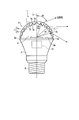
- FIG. 1 is a cross-sectional view showing a light bulb-shaped illumination device according to a first embodiment.
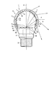
- FIG. 2 is a cross-sectional view of the translucent cover according to the first embodiment.
- FIG. 3 is a diagram illustrating a change in light distribution angle when the transmittance of the light-transmitting cover is changed.
- FIG. 4 is a cross-sectional view showing a light bulb-shaped illumination device according to a first modification.
- FIG. 5 is a cross-sectional view of a translucent cover in the illumination device according to the first modification.
- FIG. 6 is a cross-sectional view showing a light bulb-shaped illumination device according to a second modification.
- FIG. 7 is a cross-sectional view showing a light bulb-type lighting device according to another modification.
- FIG. 8 is a cross-sectional view showing a light bulb-shaped illumination device according to a third modification.
- FIG. 9 is a cross-sectional view showing a light bulb-shaped illumination device according to a fourth modification.
- FIG. 10 is a perspective view illustrating a form of a prism region of the light-transmitting cover according to the first embodiment.
- FIG. 11 is a perspective view showing a form of a prism area according to a modification.
- FIG. 12 is a perspective view illustrating a fluorescent lamp-type lighting device according to a second embodiment.
- FIG. 13 is a cross-sectional view illustrating a part of the lighting apparatus according to the second embodiment.
- 14 is a view showing a light distribution of light emitted from the portion of the lighting device shown in FIG. FIG.
- FIG. 15A is a diagram showing a light ray trajectory when a curved surface is employed in the prism area in the second embodiment.
- FIG. 15B is a diagram showing a ray trajectory when a curved surface is not adopted in the prism area.
- FIG. 16 is a perspective view showing a straight tube fluorescent lamp type illumination device according to a third embodiment.
- FIG. 17 is a cross-sectional view illustrating a part of a lighting device according to a third embodiment.
- FIG. 1 is a cross-sectional view showing an LED bulb 1 as a bulb-type lighting device according to the first embodiment.
- the LED bulb 1 has a rotationally symmetric shape with respect to the central axis.
- the LED bulb 1 includes a base material 2 having a flat mounting surface 2a on the front surface, a light source 4 composed of LEDs mounted on the mounting surface 2a, a light source 4 that covers the light source 4, and radiates light emitted from the light source to the outside.
- a translucent cover 6 having a light property.
- the translucent cover 6 has a shape that swells in a substantially hemispherical shape in the direction in which light in the normal direction 5 of the mounting surface 2a is emitted.
- the base material 2 is a metal casing and a heat dissipation member, and has a substantially circular mounting surface 2 a formed in a substantially truncated cone shape and flat at the upper end, and a base 8 is provided at the lower end of the base material 2. ing.
- the light source 4 is disposed at the center of the mounting surface 2a.
- a drive circuit 10 that drives the light source 4 is housed inside the base material 2. The power supplied from the base 8 is supplied to the light source 4 by the drive circuit 10 to emit light.
- the base material 2 holds the translucent cover 6 and the base 8 to form the outer shape of the LED bulb 1 and also serves as a heat sink and a heat sink for the heat of the light source 4.
- the translucent cover 6 is formed in a hemispherical shape with a milky white resin having a transmittance of 80%.
- the translucent cover 6 is supported on the mounting surface 2 a of the base material 2 so as to cover the light source 4, and the opening end 6 a is fixed to the peripheral portion of the mounting surface 2 a of the base material 2.
- the translucent cover 6 has a plurality of prism regions 7 integrally.
- each prism region 7 has a wedge-shaped unevenness protruding from the inner surface of the translucent cover 6.
- Each of the plurality of prism regions 7 is formed in an annular shape and is formed in a concentric shape.
- the prism region 7 includes an incident surface 7a inclined in a wedge shape so that the local thickness of the translucent cover 6 is increased in a direction away from the normal direction 5 of the mounting surface 2a, and a step surface 7b connected to the incident surface 7a. have.
- the step surface 7b is formed in an orientation in which the light source 4 is positioned on an extension in a direction parallel to the step surface 7b.
- the translucent cover 6 has a curved shape that swells in the normal direction 5 of the mounting surface 2a, light irradiation toward the back side, which cannot be realized by a prism formed on a flat surface, is also possible and further expanded. A light distribution can be obtained.
- FIG. 2 shows a cross-sectional shape of the translucent cover 6 that is actually optimized.
- the hemispherical light-transmitting cover 6 is composed of one part by injection molding.
- the region farther from the normal direction 5 of the mounting surface is the prism region so that the molded component can be removed when the component is extracted from the mold in the vertical direction (direction perpendicular to the mounting surface 2a) by injection molding. 7 is reduced.
- the prism region 7 located in a region far from the normal direction 5 of the mounting surface has a shape projecting greatly toward the light source 4 side, but is incident so as not to hinder vertical die cutting.
- the inclination of the surface 7a is constrained to be vertical at most.
- the plurality of prism regions 7 of the translucent cover 6 are regions where the unevenness is high in the prism region 7 located in the region close to the normal direction 5 of the mounting surface and is far from the normal direction of the mounting surface.
- the prism region is formed so as to be shallow (the height of the unevenness is low). Thereby, the plurality of prism regions 7 have different shapes depending on the location of the translucent cover 6.
- the light distribution angle is 182 degrees by effectively reducing the light intensity in front of the light source 4 and increasing the light intensity in the rear direction. .
- a milky white resin having a transmittance of 80% is used as a material for the light-transmitting cover 6 instead of a transparent resin.
- FIG. 3 shows the relationship between the transmittance of the translucent cover 6 and the light distribution angle.
- the horizontal axis indicates the linear transmittance of the light-transmitting cover 6, and 90% for the transparent resin and the transmittance lower than that are adjusted by changing the density of the scattering filler.
- the vertical axis represents the light distribution angle and represents the light distribution angle range in which the luminous intensity is halved.
- the characteristic line with ⁇ indicates the characteristic of the LED bulb 1 according to the first embodiment, and the characteristic line with ⁇ indicates the characteristic when a light-transmitting cover without a prism region is used as a comparative example. Yes.
- a transparent resin is used in a normal prism (Fresnel lens), but in this embodiment, the prism region is formed so as to have a diffusing action instead of a condensing action, and a widely dispersed light source 4 is used. Therefore, as shown in FIG. 3, when the transparent cover 6 including the prism area is formed of a transparent resin, the light distribution becomes jagged. In the configuration in which the light source 4 is spread and arranged (surface mounted) with respect to the translucent cover 6 as in the LED bulb 1, it is incident on the stepped surface 7b of each prism region 7 or inside the translucent cover. This is because more light rays are reflected or the like, and these lights pass through in the normal direction 5 of the mounting surface 2a. In order to reduce this, it is conceivable to form the incident surface 7a of the prism region 7 with an optimal curvature surface and to consolidate the light sources 4 to be small, but it is often difficult due to various restrictions.
- the light distribution is abruptly smoothed by giving the light transmitting cover 6 some scattering. This is because the light incident on the stepped surface 7b takes a long path length and is therefore more selectively scattered.
- FIG. 4 is a cross-sectional view of an LED bulb according to a first modification.
- the translucent cover 6 has a substantially spherical cross-sectional shape in order to expand the light distribution to the back side.
- the translucent cover 6 has an opening end 6 a at the lower end thereof fixed to the peripheral edge of the mounting surface 2 a of the substrate 2 and covers the light source 4.
- the translucent cover 6 has a maximum diameter portion larger than the diameter of the opening end 6 a, and this maximum diameter portion is located between the opening end 6 a and the upper end of the translucent cover 6.
- the translucent cover 6 is formed integrally with a plurality of prism regions 7.
- the plurality of prism regions 7 provided on the upper part A of the light-transmitting cover 6 are formed by refractive prisms as shown in FIGS. 1 and 2, and the lower part B of the light-transmitting cover 6, that is, the base material 2 side.
- the plurality of prism regions 7 provided in the upper and lower sides are formed by reflection type prisms.
- the reflection type prism region 7 the light refracted from the incident surface 7 c is totally reflected by the reflecting surface 7 d and emitted from the translucent cover 6.
- the reflection type prism region 7 has a shape protruding in the horizontal direction (a direction parallel to the mounting surface 2a of the base material 2) so that there is no light passing through without hitting the reflection surface 7d. The structure does not generate light that passes through.
- the upper part A of the translucent cover 6 is formed in a shape that can be punched in a direction perpendicular to the mounting surface 2a, and the lower part B of the translucent cover 6 Is formed in a shape that can be punched in the horizontal direction (direction parallel to the mounting surface 2a) in a vertically divided structure.
- the translucent cover 6 may be divided into a plurality of parts.
- FIG. 5 is a cross-sectional view of the translucent cover 6 actually designed.
- the light distribution angle of the LED bulb 1 is 360 degrees (the luminous intensity is more than half even in the rearward direction), and the efficiency is 92%.
- the translucent cover has a spherical cross section, but the cross sectional shape of the translucent cover may be a vertically long hemisphere or a cylinder, and preferably 1/3 of the diameter of the opening end 6a. The above-mentioned swollen height is secured.
- a plurality of dispersedly arranged LEDs are used as the light source 4 instead of the LEDs concentrated in the center.
- the light source specification is not particularly limited to this, and for example, a plurality of light sources may be arranged in a circle so as to approach the translucent cover 6.
- the prism specification may be designed to be optimal for the light emitted by the LEDs arranged at close positions. Also in the first modified example configured as described above, it is possible to irradiate light in the side surface direction or the back surface direction, and it is possible to obtain an LED bulb that is easy to manufacture.
- FIG. 6 is a cross-sectional view of an LED bulb according to a second modification.
- the translucent cover 6 has a substantially spherical cross-sectional shape in order to spread the light distribution to the back side.
- the prism area 7 of the translucent cover 6 forms the entire area in a shape that can be punched in a horizontal direction (a direction parallel to the mounting surface 2a) mainly composed of a reflective prism. For this reason, the translucent cover 6 is formed of two vertically divided injection molded parts in the horizontal direction.
- the function of the prism region 7 is weakened near the top facing the light source 4.
- a lens (lens member) 12 that faces the light source 4 is provided in the translucent cover 6, and light that is mainly emitted near the top of the translucent cover 6 by the lens 12 The direction of the side.
- an LED bulb capable of realizing a light distribution with sufficiently strong light intensity in the side surface direction and the back surface side can be obtained.
- a light shielding component 16 may be provided in the vicinity of the top of the translucent cover 6 instead of the lens 12.
- the number of divisions of the translucent cover 6 may be composed of three or more parts instead of two parts.
- a heat dissipating portion extended from the base material 2 as a member for fixing a plurality of vertically divided translucent covers 6 is provided in an arch shape along the translucent cover 6, and the vicinity of the top of the translucent cover 6 of this heat dissipating portion
- the light shielding part 16 that shields light leaking forward by expanding the area of the heat radiating part at a position corresponding to may be configured.
- the LED light bulb 1 that holds a plurality of vertically-divided translucent covers 6, adjusts the amount of light leaking forward in the weakened prism region 7 near the top by shading, and has an improved heat dissipation function. Can be realized.
- FIG. 8 is a cross-sectional view of the LED bulb 1 according to the third modification.
- the translucent cover 6 integrally having a plurality of prism regions 7 is formed in a substantially hemispherical cross-sectional shape, and is in a direction perpendicular to the mounting surface 2a of the substrate 2. It is formed in a shape that can be punched along.
- the plurality of light sources 4 are LEDs having a small light emitting area, and are arranged in a circle on the mounting surface 2a.
- annular lens (lens member) 12 is provided on the mounting surface 2 a of the substrate 2 and faces the plurality of light sources 4.
- the lens 12 has an optical characteristic that irradiates light emitted from the light source 4 more strongly in the back direction.
- the light distribution in the front direction can be expanded to the rear side by the prism region 7 of the translucent cover 6 and the light in the rear direction can be expanded by the lens 12 to the rear side.
- FIG. 9 is a cross-sectional view of the LED bulb 1 according to the fourth modification.
- the light distribution is expanded to the back side by the prism region 7 and the lens (lens member) 12 as in the third modified example described above. It is provided between the mounting surface 2 a of the material 2 and the opening end 6 a of the translucent cover 6.
- the light emitting portion of the lens 12 is exposed to the outside without being covered with the translucent cover 6. For this reason, it is possible to irradiate light to the back side more strongly than the third modified example, and the efficiency is improved as compared with the case where it is covered with the translucent cover 6.
- each prism region 7 of the translucent cover 6 has a simple wedge cross section in the rotation direction in consideration of design effort as shown in FIG.
- each prism area 7 may have a three-dimensional shape such as a pyramid shape. The detailed action distribution and pitch of the prism area 7 may be changed to an optimal one in a timely manner.
- the cross-sectional shape of the translucent cover 6 is hemispherical or spherical, but it may be cylindrical or conical. Furthermore, the translucent cover 6 may have a texture on its surface.
- FIG. 12 is a perspective view showing an LED fluorescent lamp 20 as a fluorescent lamp type illumination device according to the second embodiment
- FIG. 13 is a cross-sectional view showing a section of the LED fluorescent lamp.
- the LED fluorescent lamp 20 has a configuration in which the same cross-sectional shape is extended in a ring shape, and individual components are the same as those in the first embodiment.
- the LED fluorescent lamp 20 includes, for example, a base material 2 formed in an annular shape from a metal, and the base material has a flat annular mounting surface 2a.
- a light source 4 in which a plurality of LEDs are arranged in a ring shape is mounted on the mounting surface 2a.
- the LED fluorescent lamp 20 has a transparent cover 6 formed in an annular shape, and the transparent cover 6 has an arcuate cross-sectional shape. The translucent cover covers the plurality of light sources 4 by fixing the opening end 6 a to the substrate 2.
- the translucent cover 6 has a plurality of prism regions 7 integrally.
- each prism region 7 is formed in an annular shape over the entire circumference of the translucent cover, and has a convex portion protruding in a wedge shape from the inner surface of the translucent cover 6.
- each LED can use an SMD type with a small light emitting area, and the light source 4 has a configuration close to a point light source. Yes.
- the translucent cover 6 uses a transparent resin with little deterioration in efficiency.
- the inclined incident surface 7a of each prism region 7 is formed as a concave curved surface
- the step surface 7b is formed as a convex curved surface.
- FIG. 14 shows a light distribution in a cross section of the LED fluorescent lamp 20 shown in FIG. Since a transparent resin is used for the translucent cover 6, a butterfly light distribution with a strong side surface is realized even if the incident surface 7a is an optimal curved surface. The jaggedness of the minute light distribution can be almost eliminated by forming a wrinkle on the surface of the translucent cover 6.
- the configuration and operation of the prism region 7 are the same as those in the first embodiment, but in the second embodiment, the back surface region of the light source is irradiated, so that a sufficient inclination is also provided on the outer side edge of the translucent cover 6. Even when formed in such a manner that it can be punched in a direction perpendicular to the mounting surface 2a, a sufficient diffusing action is exhibited.
- the incident surface 7a and the stepped surface 7b forming the prism region 7 have a curved surface that becomes a concave lens in accordance with the action of diffusing light, and the material constituting the translucent cover 6 is a transparent resin with the highest efficiency.
- FIG. 15A shows a ray trajectory when the incident surface 7a and the step surface 7b are formed as curved surfaces
- FIG. 15B shows a ray trajectory when the incident surface 7a and the step surface 7b are formed as flat surfaces as a comparative example. ing.
- the irradiation direction is biased for each prism region, and the light distribution becomes jagged. This is a result of forming a discrete curvature as a lens when each prism region 7 is formed with a flat surface.
- the incident surface 7a of the prism region 7 is optimized with a concave curved surface that becomes an appropriate concave lens as in the present embodiment, and is irradiated from one prism region 7. The direction can be expanded to provide a gentle light distribution.
- the LED fluorescent lamp may have, for example, a left-right asymmetric configuration with respect to the normal direction 5 of the mounting surface 2a.
- an annular LED fluorescent lamp it is often unnecessary to irradiate the back side with respect to the inside of the ring, and the outer peripheral side is asymmetrically configured to have a more diffusing action, and the illumination direction is also changed toward the outside even at the top portion.
- a configuration incorporating the action may be adopted, and in this case, it is advantageous in terms of light distribution and efficiency.
- FIG. 16 shows an LED fluorescent lamp 30 according to the third embodiment
- FIG. 17 is an enlarged cross-sectional view showing one section of the LED fluorescent lamp.
- the LED fluorescent lamp 30 is configured as a so-called straight tube type LED fluorescent lamp in which the same cross-sectional shape is linearly extended, and individual components are the same as those in the first embodiment.
- the LED fluorescent lamp 30 includes an elongated linear substrate 2, a plurality of LEDs mounted in a straight line on the flat mounting surface 2 a of the substrate as a light source 4, and a base covering the plurality of light sources.
- a translucent cover 6 fixed to the material 2.
- the translucent cover 6 is formed in a vertically long elliptical cross-sectional shape and has a plurality of prism regions 7 integrally.
- each prism region 7 has a convex portion protruding in a wedge shape from the outer surface of the translucent cover 6.
- the convex portion has an inclined incident surface (outgoing surface) 7a and step surface 7b, and is configured such that the irradiation direction can be largely extracted toward the back side by reflecting the light beam of the light source 4 at the incident surface 7a.
- the translucent cover 6 is made of, for example, milk white resin having a transmittance of 85%. Since the cross-sectional shape of the translucent cover 6 is formed in a vertically long ellipse, there is a high probability that a light beam that returns to the inside of the translucent cover 6 due to scattering by milk white will enter the translucent cover 6 again instead of the light source 4. (Dashed arrow in the figure). Thereby, efficiency degradation is suppressed and a light distribution can be made smooth.
- the prism region 7 is provided outside the translucent cover 6, but the prism region may be provided inside the translucent cover 6, may be provided so as to protrude on both sides, or the translucent cover. You may form with the space
- the present invention is not limited to the above-described embodiments as they are, and can be embodied by modifying the constituent elements without departing from the scope of the invention in the implementation stage.
- various inventions can be formed by appropriately combining a plurality of components disclosed in the embodiment. For example, some components may be deleted from all the components shown in the embodiment.
- constituent elements over different embodiments may be appropriately combined.
- the point light source, the annular arrangement light source, and the linear arrangement light source have been described.
- a plurality of point light sources may be arranged in a matrix, and a translucent cover having a plurality of protrusions (prism regions) corresponding to the individual point light sources may be provided.
- the lighting apparatus according to the present invention can be used for street lamp illumination as long as it is a combination of a directional light source and a translucent cover surrounding the light source. Can be applied. Further, the light source is not limited to the LED, and an EL light source may be used.
Abstract
実施形態によれば、照明装置は、基材(2)と、基材の実装面(2a)に実装され、前記実装面の法線方向に指向性を有して光を放出する光源(4)と、実装面の法線方向に膨らんだ断面を有し、前記光源を覆い前記光源から放出された光を外部に放出する透光性を有する透光カバー(6)と、を備えている。透光カバーは、光源から放出された光を前記実装面の法線方向に対して拡げる方向に曲げる複数のプリズム領域(7)を有する。
Description
ここで述べる実施形態は、白色発光ダイオード(LED)のように平面実装された狭い配光分布を持つ光源を用いた照明装置に関する。
照明装置としては、白熱電球や蛍光灯が広く用いられてきたが、寿命、発光効率、水銀汚染、紫外線漏れなどの問題を抱えていた。近年、これらの問題を解消する技術として、LED光源やEL(エレクトロルミネッセンス)光源が開発され、特にLED光源は一般の照明装置への利用が加速度的に広がっている。
しかしながら、LED光源のような実装基板に実装された光源の光は、実装基板の法線方向に強く光を放出し、実装基板の法線方向とのなす角度をθとするとき、cosθに比例して光度が減衰する指向性を有している。これは、一般的なLED光源の構造が、1次光線を放出するLEDチップを、1次光線から2次光線に変換する蛍光体を含んだ保護層で実装面に平行な面状に覆った構成としているためである。このため、電球や蛍光灯にLED光源を用いた照明装置は、実装基板の法線方向の光が強く、実装基板の側方から背面方向にかけては光がほとんど出ない光度分布となる。従って、正面から背面までほぼ均一な光度分布をもつ従来の白熱電球あるいは蛍光灯と、LED光源を用いた照明装置とを置き換えた場合、天井や壁の明るさが著しく変わってしまい、違った照度空間となってしまう。
この狭い配光分布の問題を解決する技術としては、光源を構成するLEDを側面や背面方向を向けて立体的に配置する技術が提案されている。また、別の技術としては、LED光源の光により励起する蛍光体を透光カバーの内面に塗布し、透光カバー自体が光るようにする技術がある。更に別の技術としては、球状の透光カバーの下端に光源を配置する技術、あるいは、LED光源の近傍に導光体を設置する技術が提案されている。
LED光源を立体的に実装した場合、照明装置の製造組立が煩雑になるとともに、機械強度や放熱性の設計困難さが増大してしまう問題がある。また、透光カバーに蛍光体を塗布した場合も、同様に照明装置の製造組立が煩雑になる問題がある。球状の透光カバーの下端に光源を配置した場合、照明装置全体の長さ制約より基材を短くする小さくすることになり放熱が劣化してしまい大きな光量を得られない。また、導光体を設置した場合、従来の技術では十分な配光制御機能や自然なデザインを得ることが困難となる。
この発明は以上の点を鑑みてなされたもので、その課題は、側面方向あるいは背面方向まで光を照射させることができるとともに、製造が容易な照明装置を提供することにある。
実施形態によれば、照明装置は、基材と、前記基材の実装面に実装され、前記実装面の法線方向に指向性を有して光を放出する光源4と、前記実装面の法線方向に膨らんだ曲線断面を有し、前記光源を覆う透光カバーと、を備え、前記透光カバーは、前記光源から放出された光を前記実装面の法線方向に対して拡げる方向に曲げる作用を有する複数のプリズム領域を有している。
以下、図面を参照しながら、種々の実施形態に係る照明装置について詳細に説明する。
(第1の実施形態)
図1は、第1の実施形態に係る電球形の照明装置としてLED電球1を示す断面図である。LED電球1は、中心軸に対して回転対称の形状をしている。
(第1の実施形態)
図1は、第1の実施形態に係る電球形の照明装置としてLED電球1を示す断面図である。LED電球1は、中心軸に対して回転対称の形状をしている。
LED電球1は、前面に平坦な実装面2aを有する基材2と、実装面2aに実装されたLEDから成る光源4と、光源4を覆い、光源から放出された光を外部に照射する透光性を有する透光カバー6と、を備えている。透光カバー6は、実装面2aの法線方向5の光が放出される方向にほぼ半球状に膨らんだ形状を有している。
基材2は、金属製の筐体かつ放熱部材であり、ほぼ切頭円錐状に形成されて上端に平坦なほぼ円形の実装面2aを有し、基材2の下端に口金8が設けられている。光源4は、実装面2aの中心に配置されている。基材2の内部には、光源4を駆動する駆動回路10が収納されている。口金8から給電された電力は、駆動回路10により光源4に供給して発光させる構成となっている。基材2は、透光カバー6および口金8を保持してLED電球1の外面形状を形成するとともに、光源4の熱に対するヒートシンクと放熱板を兼ねている。
透光カバー6は、透過率80%の乳白樹脂で半球状に形成されている。透光カバー6は、光源4を覆うように基材2の実装面2a上に支持され、その開口端6aが基材2の実装面2aの周縁部に固定されている。
透光カバー6は、複数のプリズム領域7を一体に有している。本実施形態において、各プリズム領域7は、透光カバー6の内面から突出したクサビ状の凹凸を有している。これら複数のプリズム領域7は、それぞれ環状に形成され、同心円状に形成されている。プリズム領域7は、透光カバー6の局所的な厚さが実装面2aの法線方向5から離れる方向に厚くなるようにクサビ状に傾斜した入射面7aと、入射面7aにつなぐ段差面7bを有している。段差面7bは、これと平行な方向の延長上に光源4が位置する向きに形成されている。
このような構成によれば、光源4から放出された実装面2aの法線方向5に強い指向性をもつ光は、プリズム領域7の入射面7aからプリズム領域7に入射し、透光カバー6の表面から法線方向5よりも拡がった方向に屈折されて照射される。また、段差面7bは光源4に平行な向きであるため、光源4から段差面7bに入射する光が少なく、配光分布への影響を小さくしている。これによりLED電球1の配光分布を拡げることができる。さらには、透光カバー6は、実装面2aの法線方向5に膨らんだ曲面形状であるため、平面上に形成されたプリズムでは実現できない背面側に向けた光照射も可能となり、より拡がった配光分布を得ることができる。
図2は、実際に最適化した透光カバー6の断面形状を示している。量産性を考えると、半球状の透光カバー6は射出成型による1部品で構成するのが望ましい。図2に示すように、射出成型で上下方向(実装面2aに垂直な方向)に金型から部品を抜き取る際に成形部品が抜けるように、実装面の法線方向5から遠い領域ほどプリズム領域7の作用を小さくしている。
すなわち、実装面の法線方向5から遠い領域に位置するプリズム領域7は、光源4側に向かって大きく突出した形状とすることが望ましいが、垂直方向の型抜きの支障とならぬように入射面7aの傾斜を最大でも垂直までと制約している。その結果、透光カバー6の複数のプリズム領域7は、前記実装面の法線方向5に近い領域に位置するプリズム領域7で凹凸の高さが高く、前記実装面の法線方向から遠い領域ほど、プリズム領域が浅く(凹凸の高さが低く)なるように形成されている。これにより、複数のプリズム領域7は、透光カバー6の場所により互いに異なった形状を有している。
このような半球状の透光カバー6を用いたこの実施形態では、光源4の前方の光度を有効に低減し、背面方向の光度が増加することにより、配光角は182度となっている。
本実施形態では透光カバー6の材料として透明樹脂ではなく透過率が80%となる乳白樹脂を使っている。次に、この透光カバー6の最適透過率を説明する。
図3は、透光カバー6の透過率と配光角の関係を示している。図3において、横軸は透光カバー6の直線透過率を示し、透明樹脂で90%、それよりも低い透過率は散乱フィラの濃度を変えることで調整している。縦軸は配光角であり、光度が半減する配光角度範囲を示している。また、図3において、○の特性線は第1の実施形態に係るLED電球1による特性、□の特性線は、比較例として、プリズム領域が無い透光カバーを用いた場合の特性を示している。
通常のプリズム(フレネルレンズ)では透明樹脂を用いるが、本実施形態では、プリズム領域は集光作用ではなく拡散作用をなすように形成され、かつ、広く分散した光源4を用いている。そのため、図3に示すように、プリズム領域を含む透光カバー6を透明樹脂で形成した場合、配光分布がギザギザになってしまう。これは、LED電球1のように透光カバー6に対して光源4が拡がって配置(面実装)されている構成では、各プリズム領域7の段差面7bに入射したり、透光カバー内部で反射したりする光線が多くなり、これらの光が実装面2aの法線方向5へ抜けていくためである。これを軽減するには、プリズム領域7の入射面7aを最適な曲率面で形成することや光源4を小さく集約することが考えられるが、諸諸の制約より難しい場合が多い。
図3に示すように、透光カバー6に若干の散乱性を付与することで配光分布は急激になだらかになる。これは、段差面7bに入射した光が長い行路長を取るためより選択的に散乱作用を受けるためである。
一方、乳白による散乱が強くなりすぎると、透光カバー6の内部で散乱する効果が強くなり、プリズム領域7による作用は弱まっていく。プリズム効果は、散乱の平均自由工程が透光カバー6の厚さの1/100程度でほぼ完全に消失する。
このことから、透光カバー6の透過率としては50%から88%が最適範囲となる。 以上のように構成された第1の実施形態によれば、側面方向あるいは背面方向まで光を照射させることができるとともに、製造が容易なLED電球を得ることができる。
このことから、透光カバー6の透過率としては50%から88%が最適範囲となる。 以上のように構成された第1の実施形態によれば、側面方向あるいは背面方向まで光を照射させることができるとともに、製造が容易なLED電球を得ることができる。
次に、第1の実施形態における第1変形例に係るLED電球について説明する。なお、以下に述べる種々の変形例において、第1の実施形態と同一の部分には、同一の参照符号を付してその詳細な説明を省略し、異なる部分を中心に詳細に説明する。
図4は第1変形例に係るLED電球の断面図である。第1変形例に係るLED電球1によれば、より背面側まで配光分布を拡げるために、透光カバー6をほぼ球状の断面形状としている。透光カバー6は、その下端の開口端6aが基材2の実装面2aの周縁部に固定され、光源4を覆っている。透光カバー6は、開口端6aの径よりも大きな最大径部を有し、この最大径部は透光カバー6の開口端6aと上端との間に位置している。
透光カバー6は、複数のプリズム領域7を一体に有して形成されている。透光カバー6の上部Aに設けられた複数のプリズム領域7は、図1、図2で示したような屈折型のプリズムで形成し、透光カバー6の下部B、つまり、基材2側、に設けられた複数のプリズム領域7は反射型のプリズムで形成している。
反射型のプリズム領域7では、入射面7cから屈折入射させた光を反射面7dで全反射させて透光カバー6から放出する。反射面7dに当たらずにすり抜ける光が無いように、反射型のプリズム領域7は水平方向(基材2の実装面2aと平行な方向)に突出した形状とし、各プリズム領域7の重ね合わせですり抜ける光が生じない構成としている。
このような透光カバー6を射出成型で成型する場合、透光カバー6の上部Aは、実装面2aに垂直な方向に型抜き可能な形状に形成され、また、透光カバー6の下部Bは、縦割構造で水平方向(実装面2aと平行な方向)に型抜きが可能な形状に形成されている。この場合、透光カバー6を複数部品へ分割して形成してもよい。
図5は、実際に設計した透光カバー6の断面図である。第1変形例では、LED電球1の配光角は360度(真後ろ方向でも光度は半減以上ある)で効率は92%である。なお、第1変形例では、透光カバーは球状断面を有する構成としたが、透光カバーの断面形状は縦長半球状や円筒状としてもよいし、望ましくは開口端6aの径の1/3以上の膨らんだ高さを確保した形状とする。
図4に示すように、第1変形例では、光源4として中央に集約されたLEDではなく、複数の分散配置されたLEDを用いている。光源仕様としては特にこれに限定するものではなく、たとえば、複数の光源をサークル状に透光カバー6に近づくように配列してもよい。光源をサークル状に配列する場合、近い位置に配置されたLEDが放出する光に対して最適なプリズム仕様に設計すればよい。
このように構成された第1変形例においても、側面方向あるいは背面方向まで光を照射させることができるとともに、製造が容易なLED電球を得ることができる。
このように構成された第1変形例においても、側面方向あるいは背面方向まで光を照射させることができるとともに、製造が容易なLED電球を得ることができる。
次に、第1の実施形態における第2変形例に係るLED電球1について説明する。 図6は第2変形例に係るLED電球の断面図である。第2変形例に係るLED電球1によれば、より背面側まで配光分布を拡げるために、透光カバー6をほぼ球状の断面形状としている。透光カバー6のプリズム領域7は、反射型のプリズムを主体とした水平方向(実装面2aと平行な方向)に型抜き可能な形状で全領域を形成している。このため、透光カバー6は縦分割された2部品の水平方向型抜きの射出成型部品で形成している。
このような透光カバー6では、光源4に対向する頂上付近でプリズム領域7の機能が弱体化する。このため、第2変形例では、光源4に対向するレンズ(レンズ部材)12を透光カバー6内に設け、このレンズ12により主に透光カバー6の頂上付近に放出される光を光源4の側面方向に向けている。
このように構成された第2変形例においても、側面方向および背面側まで十分に強い光度を持った配光分布を実現可能なLED電球が得られる。
このように構成された第2変形例においても、側面方向および背面側まで十分に強い光度を持った配光分布を実現可能なLED電球が得られる。
また、図7に示す他の変形例のように、レンズ12の代わりに透光カバー6の頂上付近に遮光部品16を設けてもよい。透光カバー6の分割数も2部品ではなく3部品以上で構成してもよい。
たとえば、複数の縦分割された透光カバー6を固定する部材として基材2より延長させた放熱部を透光カバー6に沿ってアーチ状に設け、この放熱部の透光カバー6の頂上付近に対応する位置で放熱部の面積を拡げて前方に漏れる光を遮光する遮光部16を構成してもよい。このような構成では、縦分割した複数の透光カバー6を保持し、頂上付近の弱体化したプリズム領域7で前方に漏れる光量を遮光により調整するとともに、放熱機能も向上させたLED電球1を実現することができる。
次に、第1の実施形態における第3変形例に係るLED電球1について説明する。 図8は第3変形例に係るLED電球1の断面図である。第3変形例に係るLED電球1によれば、複数のプリズム領域7を一体に有する透光カバー6は、ほぼ半球状の断面形状に形成され、基材2の実装面2aに垂直な方向に沿って型抜き可能な形状に形成されている。また、実装面2aの法線方向5から遠い領域での光の拡散作用を補うため、複数の光源4は小さな発光面積のLEDであり、実装面2a上にサークル状配列している。また、基材2の実装面2a上に環状のレンズ(レンズ部材)12が設けられ、複数の光源4に対向している。レンズ12は、光源4から出射された光を、より強く背面方向に照射させる光学特性を有している。
これにより前面方向への光は透光カバー6のプリズム領域7により、背面方向の光はレンズ12により、背面側まで配光を拡大することができる。
次に、第1の実施形態における第4変形例に係るLED電球1について説明する。 図9は第4変形例に係るLED電球1の断面図である。第4変形例に係るLED電球1によれば、前述した第3変形例と同様に、プリズム領域7とレンズ(レンズ部材)12により背面側まで配光を拡げているが、レンズ12は、基材2の実装面2aと透光カバー6の開口端6aとの間に設けられている。これにより、レンズ12の光放出部分は、透光カバー6で覆わることなく、外部に露出している。このため、第3変形例よりも強く背面側に光を照射することが可能で、効率も透光カバー6で覆った場合よりも向上する。
上述した第1の実施形態、第2ないし第4変形例において、透光カバー6の各プリズム領域7は、図10に示すように、設計上の手間を考慮し単純なクサビ断面を回転方向に掃引したプリズム領域としたが、図11に示すように、各プリズム領域7は、ピラミッド状など3次元的な形態としてもよい。プリズム領域7の詳細な作用分布やピッチは、適時最適なものに変更してもよい。
また、透光カバー6の断面形状は、半球状あるいは球状としたが、円筒状や円錐状であってもよい。更に、透光カバー6は、表面にシボが施されていてもよい。
次に、他の実施形態に係る照明装置について説明する。なお、以下に述べる種々の実施形態において、第1の実施形態と同一の部分には、同一の参照符号を付してその詳細な説明を省略し、異なる部分を中心に詳細に説明する。
(第2の実施形態)
図12は、第2の実施形態に係る蛍光灯型の照明装置としてLED蛍光灯20を示す斜視図であり、図13は、LED蛍光灯の一断面を示す断面図である。LED蛍光灯20は、同じ断面形状を環状に引き延ばした構成であり、個々の構成部材は第1の実施形態と同じである。
図12は、第2の実施形態に係る蛍光灯型の照明装置としてLED蛍光灯20を示す斜視図であり、図13は、LED蛍光灯の一断面を示す断面図である。LED蛍光灯20は、同じ断面形状を環状に引き延ばした構成であり、個々の構成部材は第1の実施形態と同じである。
LED蛍光灯20は、例えば、金属により環状に形成された基材2を備え、この基材は、平坦な環状の実装面2aを有している。実装面2aには、環状に複数のLEDが配列された光源4が実装されている。LED蛍光灯20は、環状に形成された透光カバー6を有し、この透光カバー6は、円弧状の断面形状を有している。透光カバーは、その開口端6aを基材2に固定することにより、複数の光源4を覆っている。
透光カバー6は、複数のプリズム領域7を一体に有している。本実施形態では、各プリズム領域7は、透光カバーの全周に亘って環状に形成され、また、透光カバー6の内面からクサビ状に突出した凸部を有している。
本実施例の構成では、光源4が環状に長く配列されているため、個々のLEDがSMDタイプの小さい発光面積のものを使用することができ、光源4は、点光源に近い構成となっている。このため、透光カバー6は、効率劣化の小さい透明樹脂を使用している。また、各プリズム領域7の傾斜した入射面7aは、凹面曲面で形成され、段差面7bは凸曲面で形成されている。
図14は、図13に示したLED蛍光灯20の一断面部分における配光分布を示している。透光カバー6に透明樹脂を使用しているため、入射面7aを最適な曲面としても、多少ギザギザしてはいるが側面方向が強いバタフライ形の配光分布を実現している。この微小な配光分布のギザギザは、透光カバー6の表面にシボを形成することでほぼ解消することができる。
プリズム領域7の構成と作用は、第1の実施形態と同様だが、第2の実施形態では、光源の背面領域まで照射するため、透光カバー6の側面端外側にも十分な傾斜を持たせるように形成し、実装面2aに垂直な方向に型抜き可能な形状にした場合でも、十分な拡散作用を発揮させている。
プリズム領域7を形成する入射面7aと段差面7bは、光を拡散させる作用にあわせて凹レンズとなる曲面を有し、透光カバー6を構成する材料は効率が最も高くなる透明樹脂としている。
図15Aは、入射面7aと段差面7bを曲面で形成した場合の光線軌道を示し、図15Bは、比較例として、入射面7aと段差面7bを平坦面で形成した場合の光線軌道を示している。
図15Bに示すように、プリズム領域7を平坦面で形成すると、プリズム領域毎に照射方向が偏ってしまい、配光分布がギザギザになってしまう。これは、個々のプリズム領域7を平坦面で形成するとレンズとして離散的な曲率になってしまう結果である。これに対して、図15Aに示すように、本実施形態のように、プリズム領域7の入射面7aを適切な凹レンズとなる凹面曲面で最適化することにより、1つのプリズム領域7から照射される方向を拡げて全体がなだらかな配光分布とすることができる。
以上のように構成された第2の実施形態によれば、側面方向あるいは背面方向まで光を照射させることができるとともに、製造が容易なLED蛍光灯を得ることができる。 第2の実施形態において、LED蛍光灯は、実装面2aの法線方向5に対して、たとえば左右非対称な構成としてもよい。環状のLED蛍光灯では環の内側に対しては背面側への照射は不要なことが多く、非対称に外周側の方が拡散作用の強い構成とし、頂上部分でも外側に向かって照明方向を変える作用を盛り込んだ構成としてもよく、この場合、配光分布と効率点で有利となる。
(第3の実施形態)
図16は、第3の実施形態に係るLED蛍光灯30を示し、図17は、LED蛍光灯の一断面を拡大して示す断面図である。LED蛍光灯30は、同じ断面形状を直線状に引き延ばしたいわゆる直管型のLED蛍光灯として構成され、個々の構成部材は第1の実施形態と同じである。
図16は、第3の実施形態に係るLED蛍光灯30を示し、図17は、LED蛍光灯の一断面を拡大して示す断面図である。LED蛍光灯30は、同じ断面形状を直線状に引き延ばしたいわゆる直管型のLED蛍光灯として構成され、個々の構成部材は第1の実施形態と同じである。
LED蛍光灯30は、細長い直線状の基材2と、光源4として、基材の平坦な実装面2a上に直線状に並んで実装された複数のLEDと、これら複数の光源を覆って基材2に固定された透光カバー6と、を備えている。
透光カバー6は、縦長楕円状の断面形状に形成され、また、複数のプリズム領域7を一体に有している。本実施形態において、各プリズム領域7は、透光カバー6の外面からクサビ状に突出する凸部を有している。この凸部は、傾斜した入射面(出射面)7aおよび段差面7bを有し、入射面7aで光源4の光線を反射することで照射方向を背面側へ大きく取り出せるように構成している。
透光カバー6は、例えば、透過率85%の乳白樹脂で形成している。透光カバー6は、断面形状が縦長楕円に形成されているため、乳白による散乱で透光カバー6の内部に戻ってしまう光線も光源4ではなく再度透光カバー6に入射する確立が大きくなる(図の破線矢印)。これにより、効率劣化が抑制されるとともに配光分布を滑らかにすることができる。
以上のように構成された第3の実施形態によれば、側面方向あるいは背面方向まで光を照射させることができるとともに、製造が容易なLED蛍光灯を得ることができる。 第3の実施形態では、プリズム領域7を透光カバー6の外側に設けたが、プリズム領域は透光カバー6の内側でもよいし、両側に突出するように設けてもよいし、あるいは、透光カバー6の肉厚内部に設けられた空隙で形成されてもよい。
本発明は上記実施形態そのままに限定されるものではなく、実施段階ではその要旨を逸脱しない範囲で構成要素を変形して具体化できる。また、上記実施形態に開示されている複数の構成要素の適宜な組み合わせにより、種々の発明を形成できる。例えば、実施形態に示される全構成要素から幾つかの構成要素を削除してもよい。さらに、異なる実施形態にわたる構成要素を適宜組み合わせてもよい。
前述した実施形態あるいは変形例では、点状光源、環状配置光源、線状配置光源について説明したが、これに限らず、光源は他の配置展開としてもよい。例えば、複数の点状光源をマトリクス状に並べ、個々の点状光源に対応する複数突起部(プリズム領域)をもつ透光カバーを設ける構成としてもよい。
前述した実施形態あるいは変形例では、点状光源、環状配置光源、線状配置光源について説明したが、これに限らず、光源は他の配置展開としてもよい。例えば、複数の点状光源をマトリクス状に並べ、個々の点状光源に対応する複数突起部(プリズム領域)をもつ透光カバーを設ける構成としてもよい。
上述した実施形態はLED電球あるいはLED蛍光灯として説明したが、この発明に係る照明装置は、指向性のある光源とこの光源を囲う透光カバーとの組み合わせであれば、街路灯照明等についても適用することができる。また、光源は、LEDに限らず、EL光源を用いてもよい。
Claims (23)
- 基材と、
前記基材の実装面に実装され、前記実装面の法線方向に指向性を有して光を放出する光源と、
前記実装面の法線方向に膨らんだ断面を有し、前記光源を覆い前記光源から放出された光を外部に放出する透光性を有する透光カバーと、を備え、
前記透光カバーは、前記光源から放出された光を前記実装面の法線方向に対して拡げる方向に曲げる複数のプリズム領域を有する照明装置。 - 前記複数のプリズム領域は、前記透光カバーの場所により互いに異なった形状を有する請求項1に記載の照明装置。
- 前記複数のプリズム領域は、前記透光カバーの外面あるいは内面上に形成された凹凸部を有している請求項1又は2に記載の照明装置。
- 前記複数のプリズム領域は、前記透光カバーの肉厚内部に形成されている請求項1又は2に記載の照明装置。
- 前記プリズム領域は、入射面および段差面を有し、少なくとも入射面は凹曲面で形成されている請求項1又は2に記載の照明装置。
- 前記プリズム領域は、全反射をともなわない屈折だけのプリズム作用であり、プリズム作用の主面である傾斜面と前記傾斜面を接続する段差面によりプリズム領域を構成し、前記段差面に平行な面の延長上に前記光源が位置していることを特徴とする請求項1記載の照明装置。
- 前記透光カバーは、前記実装面に垂直な方向に型抜き可能な形状を有する請求項1又は2に記載の照明装置。
- 前記複数のプリズム領域は、前記実装面の法線方向に近い領域での凹凸の高さよりも、前記実装面の法線方向から遠い領域での凹凸の高さが低くなるように形成されている請求項7に記載の照明装置。
- 前記透光カバーは、前記実装面と平行な方向に型抜き可能な形状を有する請求項1又は2に記載の照明装置。
- 前記複数のプリズム領域は、前記実装面の法線方向に近い領域で凹凸の高さが高く、前記実装面の法線方向から遠い領域で凹凸の高さが低くなるように形成されている請求項9に記載の照明装置。
- 前記透光カバーは、複数の縦分割された部品より構成されている請求項9に記載の照明装置。
- 前記複数の縦分割された部品より構成される透光カバーは、放熱機能を有する保持部材により保持されている請求項11に記載の照明装置。
- 前記透光カバーは、前記実装面と垂直な方向に型抜き可能な形状を有する領域と、前記実装面と平行な方向に型抜き可能な形状を有する他の領域と、を有する請求項1又は2に記載の照明装置。
- 前記透光カバーは、透過率が50%~88%の乳白材料で形成されている請求項1又は2に記載の照明装置。
- 前記透光カバーは、表面にシボが施されている請求項1又は2に記載の照明装置。
- 前記光源に対向して設けられた遮光部材を備えている請求項1又は2に記載の照明装置。
- 前記光源に対向して設けられたレンズ部材を備えている請求項1又は2に記載の照明装置。
- 前記レンズ部材は、前記光源の前方光度を弱めて光源の側面方向から背面方向に向けた光度を強める光学特性を有している請求項17に記載の照明装置。
- 前記レンズ部材は、前記光源から放出された光の一部を光源の側面方向あるいは背面方向に向けて前記透光カバーを介さずに直接放出する請求項17に記載の照明装置。
- 前記透光カバーは、開口端の径の1/3よりも高く膨らんでいる請求項1又は2に記載の照明装置。
- 前記光源は、点状に配列され、前記透光カバーは前記光源を中心に前記実装面の法線方向に回転対称な形状である請求項1に記載の照明装置。
- 前記光源は、直線状に配列され、前記透光カバーは前記光源が配列された方向に同じ形状で引き延ばされた形状を有する請求項1に記載の照明装置。
- 前記光源は、環状に配列され、前記透光カバーは前記光源が配列された環状に同じ形状で引き延ばされた環状の形状を有する請求項1に記載の照明装置。
Applications Claiming Priority (2)
| Application Number | Priority Date | Filing Date | Title |
|---|---|---|---|
| JP2012138169A JP2014002949A (ja) | 2012-06-19 | 2012-06-19 | 照明装置 |
| JP2012-138169 | 2012-06-19 |
Publications (1)
| Publication Number | Publication Date |
|---|---|
| WO2013190979A1 true WO2013190979A1 (ja) | 2013-12-27 |
Family
ID=49768581
Family Applications (1)
| Application Number | Title | Priority Date | Filing Date |
|---|---|---|---|
| PCT/JP2013/065276 WO2013190979A1 (ja) | 2012-06-19 | 2013-05-31 | 照明装置 |
Country Status (2)
| Country | Link |
|---|---|
| JP (1) | JP2014002949A (ja) |
| WO (1) | WO2013190979A1 (ja) |
Cited By (8)
| Publication number | Priority date | Publication date | Assignee | Title |
|---|---|---|---|---|
| EP2927561A1 (en) * | 2014-03-31 | 2015-10-07 | Radiant Opto-Electronics Corporation | Lamp |
| WO2016012226A1 (en) * | 2014-07-21 | 2016-01-28 | Koninklijke Philips N.V. | Lighting device with virtual light source |
| US9709240B2 (en) | 2014-03-31 | 2017-07-18 | Radiant Opto-Electronics Corporation | Lamp |
| CN107304980A (zh) * | 2016-04-15 | 2017-10-31 | 松下知识产权经营株式会社 | 照明装置及大型陈列柜 |
| CN108826227A (zh) * | 2018-08-20 | 2018-11-16 | 叶雷 | 一种led三防灯灯罩 |
| CN109268775A (zh) * | 2018-11-13 | 2019-01-25 | 华域视觉科技(上海)有限公司 | 用于车灯的光学零件、车灯及汽车 |
| CN109708013A (zh) * | 2019-03-21 | 2019-05-03 | 上海复光竞成科技有限公司 | 一种led三防灯灯罩 |
| US11674650B2 (en) | 2019-03-26 | 2023-06-13 | Signify Holding B.V. | Light emitting device |
Families Citing this family (6)
| Publication number | Priority date | Publication date | Assignee | Title |
|---|---|---|---|---|
| JP6292509B2 (ja) * | 2014-03-07 | 2018-03-14 | パナソニックIpマネジメント株式会社 | 照明装置 |
| JP6276617B2 (ja) * | 2014-03-17 | 2018-02-07 | シチズン時計株式会社 | Led電球 |
| CN106537026B (zh) | 2014-09-02 | 2020-09-08 | 索尼公司 | 灯泡型光源装置及导光构件 |
| JP6542579B2 (ja) * | 2015-05-14 | 2019-07-10 | 日立グローバルライフソリューションズ株式会社 | Led照明装置 |
| JP2019175722A (ja) * | 2018-03-29 | 2019-10-10 | コイズミ照明株式会社 | 光学部材および照明器具 |
| KR102134078B1 (ko) * | 2018-11-29 | 2020-07-14 | 몰렉스 엘엘씨 | 발광 소자용 광 확산 렌즈 |
Citations (12)
| Publication number | Priority date | Publication date | Assignee | Title |
|---|---|---|---|---|
| JP2001210104A (ja) * | 2000-01-25 | 2001-08-03 | Shinsei Kagaku Kogyo Co Ltd | 電球用バルブ |
| JP2006173624A (ja) * | 2004-12-15 | 2006-06-29 | Shogen Koden Kofun Yugenkoshi | Led光源 |
| JP2008027695A (ja) * | 2006-07-20 | 2008-02-07 | Hayashi Kagaku Kogyo Kk | 反射体装置 |
| JP3148721U (ja) * | 2008-12-11 | 2009-02-26 | 株式会社サンテック | Led照明装置 |
| JP3152234U (ja) * | 2009-05-12 | 2009-07-23 | 益晉工業股▲ふん▼有限公司 | Ledバルブ及びそのランプカバー |
| JP2010015798A (ja) * | 2008-07-03 | 2010-01-21 | Panasonic Corp | ランプ |
| JP2011187296A (ja) * | 2010-03-08 | 2011-09-22 | Nagoya Seisakusho:Kk | 照明装置 |
| JP3173328U (ja) * | 2011-11-17 | 2012-02-02 | 株式会社昭電 | 電球型ledランプ |
| JP2012064367A (ja) * | 2010-09-15 | 2012-03-29 | Mitsubishi Electric Corp | 光源装置及び電球型照明装置 |
| JP2012074256A (ja) * | 2010-09-29 | 2012-04-12 | Panasonic Corp | ランプ |
| JP2012124048A (ja) * | 2010-12-09 | 2012-06-28 | Citizen Holdings Co Ltd | 電球型ledランプ |
| JP2013012453A (ja) * | 2011-06-02 | 2013-01-17 | Rohm Co Ltd | Ledランプ |
-
2012
- 2012-06-19 JP JP2012138169A patent/JP2014002949A/ja active Pending
-
2013
- 2013-05-31 WO PCT/JP2013/065276 patent/WO2013190979A1/ja active Application Filing
Patent Citations (12)
| Publication number | Priority date | Publication date | Assignee | Title |
|---|---|---|---|---|
| JP2001210104A (ja) * | 2000-01-25 | 2001-08-03 | Shinsei Kagaku Kogyo Co Ltd | 電球用バルブ |
| JP2006173624A (ja) * | 2004-12-15 | 2006-06-29 | Shogen Koden Kofun Yugenkoshi | Led光源 |
| JP2008027695A (ja) * | 2006-07-20 | 2008-02-07 | Hayashi Kagaku Kogyo Kk | 反射体装置 |
| JP2010015798A (ja) * | 2008-07-03 | 2010-01-21 | Panasonic Corp | ランプ |
| JP3148721U (ja) * | 2008-12-11 | 2009-02-26 | 株式会社サンテック | Led照明装置 |
| JP3152234U (ja) * | 2009-05-12 | 2009-07-23 | 益晉工業股▲ふん▼有限公司 | Ledバルブ及びそのランプカバー |
| JP2011187296A (ja) * | 2010-03-08 | 2011-09-22 | Nagoya Seisakusho:Kk | 照明装置 |
| JP2012064367A (ja) * | 2010-09-15 | 2012-03-29 | Mitsubishi Electric Corp | 光源装置及び電球型照明装置 |
| JP2012074256A (ja) * | 2010-09-29 | 2012-04-12 | Panasonic Corp | ランプ |
| JP2012124048A (ja) * | 2010-12-09 | 2012-06-28 | Citizen Holdings Co Ltd | 電球型ledランプ |
| JP2013012453A (ja) * | 2011-06-02 | 2013-01-17 | Rohm Co Ltd | Ledランプ |
| JP3173328U (ja) * | 2011-11-17 | 2012-02-02 | 株式会社昭電 | 電球型ledランプ |
Cited By (13)
| Publication number | Priority date | Publication date | Assignee | Title |
|---|---|---|---|---|
| US9709240B2 (en) | 2014-03-31 | 2017-07-18 | Radiant Opto-Electronics Corporation | Lamp |
| EP2927561A1 (en) * | 2014-03-31 | 2015-10-07 | Radiant Opto-Electronics Corporation | Lamp |
| US9719659B2 (en) | 2014-03-31 | 2017-08-01 | Radiant Opto-Electronics Corporation | Lamp |
| US9971134B2 (en) | 2014-07-21 | 2018-05-15 | Philips Lighting Holding B.V. | Lighting device with virtual light source |
| CN106662295A (zh) * | 2014-07-21 | 2017-05-10 | 飞利浦照明控股有限公司 | 具有虚拟光源的照明装置 |
| WO2016012226A1 (en) * | 2014-07-21 | 2016-01-28 | Koninklijke Philips N.V. | Lighting device with virtual light source |
| US10533711B2 (en) | 2014-07-21 | 2020-01-14 | Signify Holding B.V. | Lighting device with virtual light source |
| CN107304980A (zh) * | 2016-04-15 | 2017-10-31 | 松下知识产权经营株式会社 | 照明装置及大型陈列柜 |
| CN108826227A (zh) * | 2018-08-20 | 2018-11-16 | 叶雷 | 一种led三防灯灯罩 |
| CN108826227B (zh) * | 2018-08-20 | 2024-02-02 | 叶雷 | 一种led三防灯灯罩 |
| CN109268775A (zh) * | 2018-11-13 | 2019-01-25 | 华域视觉科技(上海)有限公司 | 用于车灯的光学零件、车灯及汽车 |
| CN109708013A (zh) * | 2019-03-21 | 2019-05-03 | 上海复光竞成科技有限公司 | 一种led三防灯灯罩 |
| US11674650B2 (en) | 2019-03-26 | 2023-06-13 | Signify Holding B.V. | Light emitting device |
Also Published As
| Publication number | Publication date |
|---|---|
| JP2014002949A (ja) | 2014-01-09 |
Similar Documents
| Publication | Publication Date | Title |
|---|---|---|
| WO2013190979A1 (ja) | 照明装置 | |
| JP5178930B1 (ja) | 照明装置 | |
| JP5010751B1 (ja) | 照明装置 | |
| JP5363864B2 (ja) | 発光装置および電球型ledランプ | |
| TWI412706B (zh) | 光源模組 | |
| JP5618097B2 (ja) | 光学デバイスおよびそれを備える発光装置 | |
| JP2012160666A (ja) | 光源モジュール及び照明装置 | |
| KR101490065B1 (ko) | 조명 장치 | |
| JP4436396B2 (ja) | 照明モジュール、光源ユニット及び照明器具 | |
| JP5292629B2 (ja) | 照明装置 | |
| JP6388649B2 (ja) | 照明デバイス | |
| JP5547697B2 (ja) | 発光装置および照明装置 | |
| JP2014102973A (ja) | 照明装置 | |
| JP6067246B2 (ja) | 照明装置 | |
| KR101150713B1 (ko) | 타원형의 광 방사 프로파일을 가진 led용 집광 렌즈 | |
| JP5575627B2 (ja) | 電球型ledランプ | |
| JP5512447B2 (ja) | 照明器具 | |
| JP5565775B2 (ja) | Led照明装置 | |
| JP2015011897A (ja) | 電球型照明装置 | |
| JP2015026451A (ja) | 電球形照明装置 | |
| JP2007258059A (ja) | 発光装置 | |
| JP2013069430A (ja) | 照明装置 | |
| JP2010114033A (ja) | 放熱効果が高く広範囲照射可能な構造を特徴とする照明用led電球。 | |
| JP2009259448A (ja) | 照明モジュール、光源ユニット及び照明器具 | |
| WO2013179687A1 (ja) | 照明装置 |
Legal Events
| Date | Code | Title | Description |
|---|---|---|---|
| 121 | Ep: the epo has been informed by wipo that ep was designated in this application |
Ref document number: 13806459 Country of ref document: EP Kind code of ref document: A1 |
|
| NENP | Non-entry into the national phase |
Ref country code: DE |
|
| 122 | Ep: pct application non-entry in european phase |
Ref document number: 13806459 Country of ref document: EP Kind code of ref document: A1 |