WO2013172276A1 - Hybrid construction machinery - Google Patents
Hybrid construction machinery Download PDFInfo
- Publication number
- WO2013172276A1 WO2013172276A1 PCT/JP2013/063199 JP2013063199W WO2013172276A1 WO 2013172276 A1 WO2013172276 A1 WO 2013172276A1 JP 2013063199 W JP2013063199 W JP 2013063199W WO 2013172276 A1 WO2013172276 A1 WO 2013172276A1
- Authority
- WO
- WIPO (PCT)
- Prior art keywords
- power
- engine
- pump
- soc
- target
- Prior art date
Links
Images


Classifications
-
- E—FIXED CONSTRUCTIONS
- E02—HYDRAULIC ENGINEERING; FOUNDATIONS; SOIL SHIFTING
- E02F—DREDGING; SOIL-SHIFTING
- E02F9/00—Component parts of dredgers or soil-shifting machines, not restricted to one of the kinds covered by groups E02F3/00 - E02F7/00
- E02F9/20—Drives; Control devices
-
- B—PERFORMING OPERATIONS; TRANSPORTING
- B60—VEHICLES IN GENERAL
- B60L—PROPULSION OF ELECTRICALLY-PROPELLED VEHICLES; SUPPLYING ELECTRIC POWER FOR AUXILIARY EQUIPMENT OF ELECTRICALLY-PROPELLED VEHICLES; ELECTRODYNAMIC BRAKE SYSTEMS FOR VEHICLES IN GENERAL; MAGNETIC SUSPENSION OR LEVITATION FOR VEHICLES; MONITORING OPERATING VARIABLES OF ELECTRICALLY-PROPELLED VEHICLES; ELECTRIC SAFETY DEVICES FOR ELECTRICALLY-PROPELLED VEHICLES
- B60L58/00—Methods or circuit arrangements for monitoring or controlling batteries or fuel cells, specially adapted for electric vehicles
- B60L58/10—Methods or circuit arrangements for monitoring or controlling batteries or fuel cells, specially adapted for electric vehicles for monitoring or controlling batteries
- B60L58/12—Methods or circuit arrangements for monitoring or controlling batteries or fuel cells, specially adapted for electric vehicles for monitoring or controlling batteries responding to state of charge [SoC]
- B60L58/15—Preventing overcharging
-
- B—PERFORMING OPERATIONS; TRANSPORTING
- B60—VEHICLES IN GENERAL
- B60L—PROPULSION OF ELECTRICALLY-PROPELLED VEHICLES; SUPPLYING ELECTRIC POWER FOR AUXILIARY EQUIPMENT OF ELECTRICALLY-PROPELLED VEHICLES; ELECTRODYNAMIC BRAKE SYSTEMS FOR VEHICLES IN GENERAL; MAGNETIC SUSPENSION OR LEVITATION FOR VEHICLES; MONITORING OPERATING VARIABLES OF ELECTRICALLY-PROPELLED VEHICLES; ELECTRIC SAFETY DEVICES FOR ELECTRICALLY-PROPELLED VEHICLES
- B60L1/00—Supplying electric power to auxiliary equipment of vehicles
- B60L1/003—Supplying electric power to auxiliary equipment of vehicles to auxiliary motors, e.g. for pumps, compressors
-
- B—PERFORMING OPERATIONS; TRANSPORTING
- B60—VEHICLES IN GENERAL
- B60L—PROPULSION OF ELECTRICALLY-PROPELLED VEHICLES; SUPPLYING ELECTRIC POWER FOR AUXILIARY EQUIPMENT OF ELECTRICALLY-PROPELLED VEHICLES; ELECTRODYNAMIC BRAKE SYSTEMS FOR VEHICLES IN GENERAL; MAGNETIC SUSPENSION OR LEVITATION FOR VEHICLES; MONITORING OPERATING VARIABLES OF ELECTRICALLY-PROPELLED VEHICLES; ELECTRIC SAFETY DEVICES FOR ELECTRICALLY-PROPELLED VEHICLES
- B60L50/00—Electric propulsion with power supplied within the vehicle
- B60L50/10—Electric propulsion with power supplied within the vehicle using propulsion power supplied by engine-driven generators, e.g. generators driven by combustion engines
- B60L50/16—Electric propulsion with power supplied within the vehicle using propulsion power supplied by engine-driven generators, e.g. generators driven by combustion engines with provision for separate direct mechanical propulsion
-
- B—PERFORMING OPERATIONS; TRANSPORTING
- B60—VEHICLES IN GENERAL
- B60W—CONJOINT CONTROL OF VEHICLE SUB-UNITS OF DIFFERENT TYPE OR DIFFERENT FUNCTION; CONTROL SYSTEMS SPECIALLY ADAPTED FOR HYBRID VEHICLES; ROAD VEHICLE DRIVE CONTROL SYSTEMS FOR PURPOSES NOT RELATED TO THE CONTROL OF A PARTICULAR SUB-UNIT
- B60W10/00—Conjoint control of vehicle sub-units of different type or different function
- B60W10/04—Conjoint control of vehicle sub-units of different type or different function including control of propulsion units
- B60W10/08—Conjoint control of vehicle sub-units of different type or different function including control of propulsion units including control of electric propulsion units, e.g. motors or generators
-
- B—PERFORMING OPERATIONS; TRANSPORTING
- B60—VEHICLES IN GENERAL
- B60W—CONJOINT CONTROL OF VEHICLE SUB-UNITS OF DIFFERENT TYPE OR DIFFERENT FUNCTION; CONTROL SYSTEMS SPECIALLY ADAPTED FOR HYBRID VEHICLES; ROAD VEHICLE DRIVE CONTROL SYSTEMS FOR PURPOSES NOT RELATED TO THE CONTROL OF A PARTICULAR SUB-UNIT
- B60W20/00—Control systems specially adapted for hybrid vehicles
-
- E—FIXED CONSTRUCTIONS
- E02—HYDRAULIC ENGINEERING; FOUNDATIONS; SOIL SHIFTING
- E02F—DREDGING; SOIL-SHIFTING
- E02F9/00—Component parts of dredgers or soil-shifting machines, not restricted to one of the kinds covered by groups E02F3/00 - E02F7/00
- E02F9/20—Drives; Control devices
- E02F9/2058—Electric or electro-mechanical or mechanical control devices of vehicle sub-units
- E02F9/2062—Control of propulsion units
- E02F9/2075—Control of propulsion units of the hybrid type
-
- E—FIXED CONSTRUCTIONS
- E02—HYDRAULIC ENGINEERING; FOUNDATIONS; SOIL SHIFTING
- E02F—DREDGING; SOIL-SHIFTING
- E02F9/00—Component parts of dredgers or soil-shifting machines, not restricted to one of the kinds covered by groups E02F3/00 - E02F7/00
- E02F9/20—Drives; Control devices
- E02F9/22—Hydraulic or pneumatic drives
- E02F9/2246—Control of prime movers, e.g. depending on the hydraulic load of work tools
-
- E—FIXED CONSTRUCTIONS
- E02—HYDRAULIC ENGINEERING; FOUNDATIONS; SOIL SHIFTING
- E02F—DREDGING; SOIL-SHIFTING
- E02F9/00—Component parts of dredgers or soil-shifting machines, not restricted to one of the kinds covered by groups E02F3/00 - E02F7/00
- E02F9/20—Drives; Control devices
- E02F9/22—Hydraulic or pneumatic drives
- E02F9/2278—Hydraulic circuits
- E02F9/2296—Systems with a variable displacement pump
-
- F—MECHANICAL ENGINEERING; LIGHTING; HEATING; WEAPONS; BLASTING
- F02—COMBUSTION ENGINES; HOT-GAS OR COMBUSTION-PRODUCT ENGINE PLANTS
- F02D—CONTROLLING COMBUSTION ENGINES
- F02D29/00—Controlling engines, such controlling being peculiar to the devices driven thereby, the devices being other than parts or accessories essential to engine operation, e.g. controlling of engines by signals external thereto
- F02D29/04—Controlling engines, such controlling being peculiar to the devices driven thereby, the devices being other than parts or accessories essential to engine operation, e.g. controlling of engines by signals external thereto peculiar to engines driving pumps
-
- B—PERFORMING OPERATIONS; TRANSPORTING
- B60—VEHICLES IN GENERAL
- B60L—PROPULSION OF ELECTRICALLY-PROPELLED VEHICLES; SUPPLYING ELECTRIC POWER FOR AUXILIARY EQUIPMENT OF ELECTRICALLY-PROPELLED VEHICLES; ELECTRODYNAMIC BRAKE SYSTEMS FOR VEHICLES IN GENERAL; MAGNETIC SUSPENSION OR LEVITATION FOR VEHICLES; MONITORING OPERATING VARIABLES OF ELECTRICALLY-PROPELLED VEHICLES; ELECTRIC SAFETY DEVICES FOR ELECTRICALLY-PROPELLED VEHICLES
- B60L2240/00—Control parameters of input or output; Target parameters
- B60L2240/40—Drive Train control parameters
- B60L2240/42—Drive Train control parameters related to electric machines
- B60L2240/423—Torque
-
- B—PERFORMING OPERATIONS; TRANSPORTING
- B60—VEHICLES IN GENERAL
- B60L—PROPULSION OF ELECTRICALLY-PROPELLED VEHICLES; SUPPLYING ELECTRIC POWER FOR AUXILIARY EQUIPMENT OF ELECTRICALLY-PROPELLED VEHICLES; ELECTRODYNAMIC BRAKE SYSTEMS FOR VEHICLES IN GENERAL; MAGNETIC SUSPENSION OR LEVITATION FOR VEHICLES; MONITORING OPERATING VARIABLES OF ELECTRICALLY-PROPELLED VEHICLES; ELECTRIC SAFETY DEVICES FOR ELECTRICALLY-PROPELLED VEHICLES
- B60L2240/00—Control parameters of input or output; Target parameters
- B60L2240/40—Drive Train control parameters
- B60L2240/44—Drive Train control parameters related to combustion engines
- B60L2240/441—Speed
-
- B—PERFORMING OPERATIONS; TRANSPORTING
- B60—VEHICLES IN GENERAL
- B60L—PROPULSION OF ELECTRICALLY-PROPELLED VEHICLES; SUPPLYING ELECTRIC POWER FOR AUXILIARY EQUIPMENT OF ELECTRICALLY-PROPELLED VEHICLES; ELECTRODYNAMIC BRAKE SYSTEMS FOR VEHICLES IN GENERAL; MAGNETIC SUSPENSION OR LEVITATION FOR VEHICLES; MONITORING OPERATING VARIABLES OF ELECTRICALLY-PROPELLED VEHICLES; ELECTRIC SAFETY DEVICES FOR ELECTRICALLY-PROPELLED VEHICLES
- B60L2240/00—Control parameters of input or output; Target parameters
- B60L2240/40—Drive Train control parameters
- B60L2240/44—Drive Train control parameters related to combustion engines
- B60L2240/443—Torque
-
- B—PERFORMING OPERATIONS; TRANSPORTING
- B60—VEHICLES IN GENERAL
- B60L—PROPULSION OF ELECTRICALLY-PROPELLED VEHICLES; SUPPLYING ELECTRIC POWER FOR AUXILIARY EQUIPMENT OF ELECTRICALLY-PROPELLED VEHICLES; ELECTRODYNAMIC BRAKE SYSTEMS FOR VEHICLES IN GENERAL; MAGNETIC SUSPENSION OR LEVITATION FOR VEHICLES; MONITORING OPERATING VARIABLES OF ELECTRICALLY-PROPELLED VEHICLES; ELECTRIC SAFETY DEVICES FOR ELECTRICALLY-PROPELLED VEHICLES
- B60L2240/00—Control parameters of input or output; Target parameters
- B60L2240/40—Drive Train control parameters
- B60L2240/54—Drive Train control parameters related to batteries
- B60L2240/545—Temperature
-
- B—PERFORMING OPERATIONS; TRANSPORTING
- B60—VEHICLES IN GENERAL
- B60L—PROPULSION OF ELECTRICALLY-PROPELLED VEHICLES; SUPPLYING ELECTRIC POWER FOR AUXILIARY EQUIPMENT OF ELECTRICALLY-PROPELLED VEHICLES; ELECTRODYNAMIC BRAKE SYSTEMS FOR VEHICLES IN GENERAL; MAGNETIC SUSPENSION OR LEVITATION FOR VEHICLES; MONITORING OPERATING VARIABLES OF ELECTRICALLY-PROPELLED VEHICLES; ELECTRIC SAFETY DEVICES FOR ELECTRICALLY-PROPELLED VEHICLES
- B60L2240/00—Control parameters of input or output; Target parameters
- B60L2240/40—Drive Train control parameters
- B60L2240/54—Drive Train control parameters related to batteries
- B60L2240/547—Voltage
-
- B—PERFORMING OPERATIONS; TRANSPORTING
- B60—VEHICLES IN GENERAL
- B60L—PROPULSION OF ELECTRICALLY-PROPELLED VEHICLES; SUPPLYING ELECTRIC POWER FOR AUXILIARY EQUIPMENT OF ELECTRICALLY-PROPELLED VEHICLES; ELECTRODYNAMIC BRAKE SYSTEMS FOR VEHICLES IN GENERAL; MAGNETIC SUSPENSION OR LEVITATION FOR VEHICLES; MONITORING OPERATING VARIABLES OF ELECTRICALLY-PROPELLED VEHICLES; ELECTRIC SAFETY DEVICES FOR ELECTRICALLY-PROPELLED VEHICLES
- B60L2240/00—Control parameters of input or output; Target parameters
- B60L2240/40—Drive Train control parameters
- B60L2240/54—Drive Train control parameters related to batteries
- B60L2240/549—Current
-
- B—PERFORMING OPERATIONS; TRANSPORTING
- B60—VEHICLES IN GENERAL
- B60L—PROPULSION OF ELECTRICALLY-PROPELLED VEHICLES; SUPPLYING ELECTRIC POWER FOR AUXILIARY EQUIPMENT OF ELECTRICALLY-PROPELLED VEHICLES; ELECTRODYNAMIC BRAKE SYSTEMS FOR VEHICLES IN GENERAL; MAGNETIC SUSPENSION OR LEVITATION FOR VEHICLES; MONITORING OPERATING VARIABLES OF ELECTRICALLY-PROPELLED VEHICLES; ELECTRIC SAFETY DEVICES FOR ELECTRICALLY-PROPELLED VEHICLES
- B60L2270/00—Problem solutions or means not otherwise provided for
- B60L2270/10—Emission reduction
- B60L2270/12—Emission reduction of exhaust
-
- H—ELECTRICITY
- H02—GENERATION; CONVERSION OR DISTRIBUTION OF ELECTRIC POWER
- H02H—EMERGENCY PROTECTIVE CIRCUIT ARRANGEMENTS
- H02H7/00—Emergency protective circuit arrangements specially adapted for specific types of electric machines or apparatus or for sectionalised protection of cable or line systems, and effecting automatic switching in the event of an undesired change from normal working conditions
- H02H7/08—Emergency protective circuit arrangements specially adapted for specific types of electric machines or apparatus or for sectionalised protection of cable or line systems, and effecting automatic switching in the event of an undesired change from normal working conditions for dynamo-electric motors
- H02H7/0833—Emergency protective circuit arrangements specially adapted for specific types of electric machines or apparatus or for sectionalised protection of cable or line systems, and effecting automatic switching in the event of an undesired change from normal working conditions for dynamo-electric motors for electric motors with control arrangements
-
- Y—GENERAL TAGGING OF NEW TECHNOLOGICAL DEVELOPMENTS; GENERAL TAGGING OF CROSS-SECTIONAL TECHNOLOGIES SPANNING OVER SEVERAL SECTIONS OF THE IPC; TECHNICAL SUBJECTS COVERED BY FORMER USPC CROSS-REFERENCE ART COLLECTIONS [XRACs] AND DIGESTS
- Y02—TECHNOLOGIES OR APPLICATIONS FOR MITIGATION OR ADAPTATION AGAINST CLIMATE CHANGE
- Y02T—CLIMATE CHANGE MITIGATION TECHNOLOGIES RELATED TO TRANSPORTATION
- Y02T10/00—Road transport of goods or passengers
- Y02T10/60—Other road transportation technologies with climate change mitigation effect
- Y02T10/64—Electric machine technologies in electromobility
-
- Y—GENERAL TAGGING OF NEW TECHNOLOGICAL DEVELOPMENTS; GENERAL TAGGING OF CROSS-SECTIONAL TECHNOLOGIES SPANNING OVER SEVERAL SECTIONS OF THE IPC; TECHNICAL SUBJECTS COVERED BY FORMER USPC CROSS-REFERENCE ART COLLECTIONS [XRACs] AND DIGESTS
- Y02—TECHNOLOGIES OR APPLICATIONS FOR MITIGATION OR ADAPTATION AGAINST CLIMATE CHANGE
- Y02T—CLIMATE CHANGE MITIGATION TECHNOLOGIES RELATED TO TRANSPORTATION
- Y02T10/00—Road transport of goods or passengers
- Y02T10/60—Other road transportation technologies with climate change mitigation effect
- Y02T10/70—Energy storage systems for electromobility, e.g. batteries
-
- Y—GENERAL TAGGING OF NEW TECHNOLOGICAL DEVELOPMENTS; GENERAL TAGGING OF CROSS-SECTIONAL TECHNOLOGIES SPANNING OVER SEVERAL SECTIONS OF THE IPC; TECHNICAL SUBJECTS COVERED BY FORMER USPC CROSS-REFERENCE ART COLLECTIONS [XRACs] AND DIGESTS
- Y02—TECHNOLOGIES OR APPLICATIONS FOR MITIGATION OR ADAPTATION AGAINST CLIMATE CHANGE
- Y02T—CLIMATE CHANGE MITIGATION TECHNOLOGIES RELATED TO TRANSPORTATION
- Y02T10/00—Road transport of goods or passengers
- Y02T10/60—Other road transportation technologies with climate change mitigation effect
- Y02T10/7072—Electromobility specific charging systems or methods for batteries, ultracapacitors, supercapacitors or double-layer capacitors
-
- Y—GENERAL TAGGING OF NEW TECHNOLOGICAL DEVELOPMENTS; GENERAL TAGGING OF CROSS-SECTIONAL TECHNOLOGIES SPANNING OVER SEVERAL SECTIONS OF THE IPC; TECHNICAL SUBJECTS COVERED BY FORMER USPC CROSS-REFERENCE ART COLLECTIONS [XRACs] AND DIGESTS
- Y10—TECHNICAL SUBJECTS COVERED BY FORMER USPC
- Y10S—TECHNICAL SUBJECTS COVERED BY FORMER USPC CROSS-REFERENCE ART COLLECTIONS [XRACs] AND DIGESTS
- Y10S903/00—Hybrid electric vehicles, HEVS
- Y10S903/902—Prime movers comprising electrical and internal combustion motors
- Y10S903/903—Prime movers comprising electrical and internal combustion motors having energy storing means, e.g. battery, capacitor
- Y10S903/93—Conjoint control of different elements
Definitions
- the present invention relates to a hybrid construction machine such as a hydraulic shovel or a wheel loader provided with an engine and an electric motor / generator as a power source.
- Construction machines (hydraulic shovels, wheel loaders, etc.) aimed at energy saving (low fuel consumption) and emission reduction of exhaust gases (carbon dioxide, nitrogen oxides, particulate matter, etc.) discharged from the engine and causing environmental load
- a so-called hybrid construction machine equipped with a motor / generator as a power source in addition to an engine.
- Japanese Patent No. 4633813 As a technology of a hybrid construction machine, a technology for avoiding the decrease in engine combustion efficiency and preventing the generation of black smoke (exhaust gas) is disclosed in Japanese Patent No. 4633813. According to this technology, the engine upper limit value is increased according to a certain increase rate to prevent the engine from sharply increasing the power to suppress the exhaust gas.
- Japanese Patent No. 4512283 prevents excessive supply of the total power of the engine and the motor / generator by adjusting the excess / shortage of the supply power of the engine to the required power of the hydraulic pump through charge / discharge operation by the motor / generator. There is disclosed a technology for improving fuel efficiency and preventing engine stall caused by insufficient power supply to a hydraulic pump.
- Patent No. 4633813 Patent No. 4512283 JP 2003-9308 A
- the power change speed of the engine is limited by increasing the output upper limit value of the engine at a predetermined increase rate, but when the required power of the pump exceeds the output upper limit of the engine , The difference is compensated by the power of the motor. Therefore, for example, during the work where the necessary power rapidly increases such as the excavating operation of a shovel, the power that can be supplied to the pump is insufficient when the storage capacity is small and sufficient power assistance can not be performed from the motor. Therefore, it is inevitable that the operation of the shovel will be slow. Furthermore, in such a situation, if the power that can be supplied from the engine and the motor / generator is much lower than the required pump power, the engine may be stalled.
- the present invention has been made in view of the above problems, and it is an object of the present invention to provide a hybrid construction machine capable of maintaining an operator's operation feeling well while reducing fuel consumption and exhaust gas. To aim.
- the present invention provides an engine, a motor / generator for transmitting torque between the engine, and a hydraulic pump driven by at least one of the engine and the motor / generator.
- a hydraulic actuator driven by pressure oil discharged from the hydraulic pump, a power storage device for supplying electric power to the motor / generator, and the engine and the electric motor so as to satisfy the required power of the hydraulic pump
- control means for setting a target power of the generator, wherein the control means monotonously increases the limit value of the target power of the engine according to a decrease in the remaining amount of charge of the power storage device.
- the motor / generator with high responsiveness preferentially outputs the pump request power when the storage residual amount is relatively large, and depends on the storage residual amount when the storage residual amount is relatively small. Since the non-performing engine preferentially outputs the pump request power, it is possible to secure a good operation feeling regardless of the remaining amount of stored power and to reduce the fuel consumption and the exhaust gas.
- FIG. 7 is a schematic configuration diagram of a controller according to a second embodiment of the present invention.
- requirement motive power, engine target motive power, and assist target motive power in case SOC is large.
- requirement motive power, engine target motive power, and assist target motive power in case SOC is small.
- the simple explanatory view about how to decide the engine target motive power in case SOC is low.
- FIG. 1 is a schematic configuration diagram of a hydraulic drive control device in a hybrid hydraulic shovel according to an embodiment of the present invention.
- the hydraulic drive control device shown in this figure includes an engine 1, a governor 7 for adjusting the fuel injection amount of the engine 1, a rotation number sensor (actual rotation number detection means) 6 for detecting an actual rotation number of the engine 1, and an engine A motor / generator 2 mechanically connected to the output shaft of 1 and transmitting torque with the engine 1, and mechanically connected to the output shafts of the engine 1 and the motor / generator 2 Driven by pressure oil discharged from the variable displacement hydraulic pump 3 (hereinafter may be simply referred to as "hydraulic pump 3") and pilot pump 32 driven by at least one of the motor / generator 2 and the hydraulic pump 3 And a control lever for controlling the hydraulic actuator 5 by reducing the pressure oil discharged from the pilot pump 32 and outputting the pressure oil to the valve device 4 (operation 16), a storage device (storage means) 10 for storing electric power
- the hydraulic drive control device shown in FIG. 1 first supplies the pressure oil discharged by the hydraulic pump 3 to the valve device 4 provided with a plurality of control valves, and the valve device 4 appropriately changes the flow rate, direction, and pressure of the pressure oil.
- the drive of each hydraulic actuator 5 is controlled by supplying each hydraulic actuator 5 later.
- the control valve in the valve device 4 is controlled by pressure oil discharged from the pilot pump 32 and reduced in pressure according to the amount of operation of the control lever 16.
- the operation amount of the operation lever 16 can be detected by detecting the pressure of the pressure oil output from the pilot pump 32 to the valve device 4 (control valve) by pressure detection means such as the pressure sensors 18a and 18b (see FIG. 1). .
- a hydraulic cylinder (a boom cylinder, an arm cylinder, and a bucket for driving an articulated working device attached to the front of the upper swing body)
- a hydraulic motor for swinging the upper swing body
- a hydraulic motor for running the lower traveling body attached to the lower portion of the upper swing body
- the engine 1 is controlled by controlling the fuel injection amount by the governor 7.
- the pressure pump 19 measures pressure of the pressure oil discharged from the hydraulic pump 3 as a means (pump information detecting means) for detecting information necessary to calculate the load of the hydraulic pump 3 (a pressure sensor 19 A detection means), a flow rate sensor (flow rate detection means) (not shown) for measuring the flow rate of the pressure oil, and an angle sensor (angle detection means) (not shown) for measuring the tilt angle of the hydraulic pump 3;
- the pressure sensor 19, the flow rate sensor and the angle sensor output the detected sensor values to the controller 8.
- the regulator 14 and the solenoid proportional valve 15 are pump displacement adjusting devices that adjust the displacement of the hydraulic pump 3 based on an operation signal output from the controller 8.
- the regulator 14 is provided to the hydraulic pump 3, and when the tilt angle of the swash plate or the oblique shaft of the hydraulic pump 3 is operated by the regulator 14, the displacement (displacement volume) of the hydraulic pump 3 is changed to absorb the hydraulic pump 3. Torque (input torque) can be controlled (pump absorption torque control).
- the hydraulic proportional valve 15 is supplied with pressure oil through a pipe (not shown) connected to the pilot pump 32.
- the regulator 14 in the present embodiment is controlled by the control pressure generated by the solenoid proportional valve 15.
- the solenoid proportional valve 15 operates based on the command value output from the controller 8.
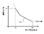
- the regulator 14 controls, for example, the displacement of the hydraulic pump 3 in accordance with the control characteristic diagram shown in FIG. FIG. 2 is a control characteristic diagram of pump absorption torque by the regulator 14 according to the embodiment of the present invention.
- the broken line 31A shown in this figure shows the characteristic of the capacity of the hydraulic pump 3 set with respect to the discharge pressure of the hydraulic pump 3, and the maximum value of the total output of the engine 1 and the motor / generator 2 (in FIG.
- the torque (product of the pump displacement and the pump discharge pressure) of the hydraulic pump 3 is set to be substantially constant within a range not exceeding the hyperbola (constant torque diagram) indicated by the broken line in FIG.
- the torque of hydraulic pump 3 is controlled so as not to exceed the maximum output by engine 1 and motor / generator 2 it can.
- the pump discharge pressure is P1 or less
- the pump absorption torque control is not performed, and the pump displacement is determined by the operation amount of the operation lever for operating each control valve of the valve device 4 (for example, any operation lever Becomes q1 when the operation amount of is the maximum).
- the pump discharge pressure becomes P1 to P2
- the pump absorption torque control by the regulator 14 is executed, and the pump displacement angle by the regulator 14 decreases the pump displacement along the broken line 31A with the increase of the pump discharge pressure. Is operated.
- the pump absorption torque is controlled to be equal to or less than the torque specified by the broken line 31A.
- P2 is the maximum value of the pump discharge pressure, which is equal to the set pressure of the relief valve connected to the circuit on the hydraulic pump 3 side in the valve device 4, and the pump discharge pressure does not rise above this value.
- a broken line 31A in which two straight lines are combined is used as a control characteristic diagram of absorption torque of the hydraulic pump, but if it is set in a range not exceeding the constant torque diagram (hyperbola) in FIG.
- a control characteristic chart may be used.
- the controller 8 outputs an operation signal (electric signal) generated based on the absorption torque of the hydraulic pump 3 to the solenoid proportional valve 15, and the solenoid proportional valve 15 generates the control pressure according to the operation signal, thereby regulating the regulator 14. Drive.
- the capacity of the hydraulic pump 3 is changed by the regulator 14, and the absorption torque of the hydraulic pump 3 is adjusted to a range where engine stall does not occur.
- the power storage device 10 configured of a battery, a capacitor, or the like includes a current sensor 11, a voltage sensor 12, and a temperature sensor as means (power storage information detection means) for detecting information required to calculate the storage amount of the power storage device 10. 13 is attached.
- the controller 8 calculates the remaining charge amount of the power storage device 10 in the remaining charge amount calculation unit 21 (described later) based on the information such as the current, voltage and temperature detected by the sensors 11, 12, 13 Control the storage capacity of
- FIG. 3 is a schematic block diagram of the controller 8 according to the first embodiment of the present invention.
- the same reference numerals are given to the same parts as the parts shown in the previous figures, and the description may be omitted as appropriate (the same applies to the latter figures).
- the controller 8 shown in this figure mainly executes processing for setting the target power of the engine 1 and the motor / generator 2 so as to satisfy the required power of the hydraulic pump 3.
- the engine target power calculation unit 23, the pump power calculation unit 22, the motor / generator target power calculation unit 34, the assist power control unit 28, the engine target rotation speed calculation unit 35, and the engine target rotation speed control unit 36 Have.
- the controller 8 has, as a hardware configuration, an arithmetic processing unit (for example, a CPU) for executing various processing programs according to the present invention, and a storage unit (for example, a ROM) for storing various data including the control program. , RAM) etc. (all not shown).
- arithmetic processing unit for example, a CPU
- a storage unit for example, a ROM
- control is implemented by the controller 8 also regarding a hydraulic system, various electrical components, etc., detailed description is abbreviate
- a storage residual amount calculation unit (storage residual amount calculation means) 21 calculates the storage residual amount (SOC: State Of Charge (hereinafter sometimes referred to as SOC)) of the storage device 10 and outputs the storage residual amount. It is a part that performs processing.
- SOC State Of Charge
- a known method may be used as a method of calculating the remaining charge amount, for example, based on information such as current, voltage and temperature detected by the current sensor 11, the voltage sensor 12 and the temperature sensor 13. There are some that calculate the remaining amount.
- the engine target power calculation unit (engine target power calculation means) 23 is a part that executes processing to calculate the target power (engine target power) of the engine 1 based on the SOC output from the stored power amount calculation unit 21. .
- the engine target power is set by the engine target power calculation unit 23 so as to monotonously increase as the SOC decreases.
- “monotonically increasing” includes not only “(1) monotonous increase in a narrow sense that engine target power always increases with decrease in SOC, but (2) engine target power is specified with decrease in SOC
- the term “monotonic increase in a broad sense” which increases stepwise (discretely) while being held constant in the SOC section of the term is also included (Note that “monotonic increase in a broad sense” is an engine target along with a decrease in SOC). It is sometimes called “monotonous non-decreasing" because the power increases without decreasing.
- the engine target power calculation unit 23 in the present embodiment uses a power calculation table shown in FIG. 4 when calculating the engine target power based on the SOC.
- FIG. 4 is a diagram showing a power calculation table according to the first embodiment of the present invention.
- the horizontal axis represents SOC, which is an input from the remaining charge amount calculation unit 21, and the target power, which is the output of the engine target power calculation unit 23, is vertical axis.
- the engine target power is set to increase stepwise (in a broad sense, monotonically increases) according to the decrease in SOC, and the entire table is viewed The engine target power is increasing with the left shoulder rising, and there is no part of the left shoulder falling.
- the engine target power is set low, and the fuel consumption is reduced by lowering the target power of the engine 1
- the engine target power is set to be large. That is, when the SOC is low, the frequency of using the motor / generator 2 as a generator is increased to avoid the situation where the power storage device 10 is overdischarged.
- the engine target power is set to the maximum power of the engine 1, and the SOC is S2 (second set value
- the engine target power is set to a value smaller than the minimum power of the hydraulic pump 3. That is, when the SOC is equal to or greater than S2, the motor / generator 2 operates as a motor.
- a table in which the engine target power monotonously increases in a step-like manner (monotonous increase in a broad sense) with SOC decrease is used. It was. Setting the table in this manner is also advantageous in that the used capacity of the storage device can be further suppressed and that the calculation speed of the arithmetic processing unit can be improved. Also, the design method of the table is not limited to this, and for example, as described later, the engine target power always increases (monotonously increases in a narrow sense) according to the decrease of SOC (for example, a curved graph) You may use
- the pump power calculation unit (pump power calculation means) 22 is a part that calculates a required power (pump required power) of the hydraulic pump 3 and executes a process of outputting the pump required power.
- a method of calculating the required power of the hydraulic pump 3 for example, there is a method of inputting the operation amount (lever operation amount) of the operation lever 16 and calculating the required power based on the magnitude of the operation amount.
- a method of obtaining the operation amount of the operation lever 16 there is a method using detection values of the pressure sensors 18a and 18b.
- the actual pump power output from the hydraulic pump 3 may be regarded as the pump request power.
- a method of calculating the actual pump power for example, there is a method of multiplying the pump discharge pressure detected through the pressure sensor 19 and the pump discharge flow rate detected through the flow sensor.
- the motor / generator target power calculation unit (motor / generator target power calculation means) 34 executes processing for calculating the target power (assist target power) of the motor / generator 2 based on the engine target power and the pump required power.
- the assist target power calculated here is converted into an assist power command and is output to the assist power control unit 28.
- the motor / generator 2 When the assist target power is a positive value (that is, in the case of “pump required power> engine target power”), the motor / generator 2 operates as a motor using the power of the charging device 10, and is a negative value. (That is, in the case of "pump required power ⁇ engine target power”) is driven by the engine 1 and operates as a generator.
- the assist power control unit (assist power control means) 28 controls the motor / generator 2 based on the assist power command, and corresponds to the inverter 9 in FIG.
- the engine target rotation speed calculation unit (target rotation speed calculation means) 35 is a part that executes processing for calculating the target rotation speed of the engine 1 based on the engine target power output from the engine target power calculation unit 23.
- a method of calculating the target rotational speed for example, a combination that achieves the desired fuel efficiency is selected from among a plurality of combinations of rotational speed and torque that can achieve the engine target power input from the engine target power calculation unit 23 In some cases, the number of revolutions related to the combination is set as the target number of revolutions.
- the engine target rotation speed calculated here is converted into a target rotation speed command and output to the engine target rotation speed control unit 36.
- the engine target speed control unit (engine control means) 36 is a part that controls the engine 1 based on the target speed command, and corresponds to the governor 7 in FIG. 1.
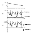
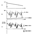
- FIG. 5 shows that the SOC, the pump required power, the engine target power, and the assist target power are the motor and generator targets when the SOC is S2 or more and is sufficiently large (for example, at the start of work the day after the night charge).
- FIG. 6 is a diagram showing a change in the aforementioned assist power command converted by the power calculation unit 34.
- the SOC is equal to or greater than S2
- the engine target power starts from the minimum value.
- the SOC is equal to or greater than S2
- the minimum value of the engine target power is set to be equal to or less than the minimum power of the hydraulic pump 3.
- the motor / generator 2 is not operated as a generator, and only operates or stops operation as a motor.
- the SOC gradually decreases as shown in FIG. 5 (a).
- the engine target power is kept constant (minimum value).
- the assist power command (assist target power) to the motor / generator 2 shown in FIG. 5C works on the assisting side (assist side), so the pump can be operated even if the actual power of the engine 1 is kept substantially constant. It is possible to easily follow changes in required power.
- the motor generator 2 is more responsive than the engine 1, the operator's operation feeling can be well maintained.
- the fuel consumption by the engine 1 can be suppressed, the fuel consumption and the exhaust gas can be reduced.
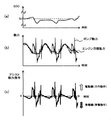
- FIG. 5 shows the operation when the SOC decreases to a value larger than S1 and smaller than S2
- FIG. 6 shows the SOC, the pump required power, the engine target power and the assist target power (ie, the assist power) when the SOC is greater than S1 and less than S2 (more specifically, greater than Sa in FIG. 4 and less than Sb). Is a diagram showing a change of command).
- the engine target power calculated by the engine target power calculation unit 23 in accordance with the decrease in the SOC is a higher value than in the case of FIG. Therefore, while the engine target power is held constant, the assist power command of the motor / generator 2 calculated by "pump required power-engine target power" repeats charging and discharging as shown in FIG. 6 (c). .
- the engine target power is adjusted to be approximately the median (for example, moving average value) of the pump required power or a value slightly higher than the median. It is preferable to keep it.
- the adjustment of the engine target power may be performed by predicting the pump required power from the operation amount of the operation lever 16 and sequentially rewriting the operation table, or in the case where the work content of the hydraulic shovel is known in advance You may do according to the work content.
- the engine target power takes the median value of the pump required power, so the assist power command of the motor / generator 2 repeats charging and discharging as shown in FIG.
- the SOC is maintained at a constant level while suppressing a sharp change in the power of the engine 1.
- FIG. 7 is a diagram showing changes in the SOC, the pump required power, the engine target power, and the assist target power (that is, the assist power command) when the SOC is less than S1.
- the engine target power calculated by the engine target power calculation unit 23 is set to the maximum value of the engine power. Therefore, the motor / generator 2 is not operated as a motor, and only operates or stops operation as a generator. Therefore, as shown in FIG. 7A, the SOC tends to increase with the passage of time.
- the engine target power when the SOC is low, the engine that does not depend on the magnitude of the SOC preferentially outputs the pump request power, so that the operator's operation feeling can be well maintained. Further, at that time, since the engine 1 is operated at the rated output point (maximum power), the combustion state of the engine 1 is stabilized and the content of the substance included in the exhaust gas that gives environmental load is suppressed. Further, when the pump required power is small, power is generated at a high output point where the efficiency of the engine 1 is good, so improvement in fuel consumption can also be expected. Furthermore, if the engine 1 capable of outputting power equal to or greater than the maximum value of the pump required power is used, power shortage for the pump required power does not occur, so that the operator's operation feeling can always be maintained well.
- S1 (refer FIG. 4) of SOC based on the change profile of the pump motive power which concerns on the construction machine to which this invention is applied.
- the pump required power may be instantaneously increased mainly at the time of excavating operation, but even in such a case, assist power capable of suppressing a rapid change in engine power.
- S1 so as to secure the power enough to generate the S1 is preferably designed with some margin for this minimum power.
- the power required by the motor / generator 2 (assist power) mainly bears the required pump power, so the engine 1 In this case, transient fuel injection is suppressed and the content of substances having environmental burden in exhaust gas is suppressed. Further, when the SOC decreases, the load by the engine 1 is increased. Therefore, even when sufficient assist power can not be output because the SOC is small, the pump required power can be secured by the engine 1. That is, in all the states of FIGS. 5 to 7, it can be confirmed that the required power of the hydraulic pump 3 can be secured by the sum of the power of the engine 1 and the motor / generator 2. Therefore, according to the present embodiment, hydraulic actuator 5 can be operated at a speed equivalent to that of a conventional construction machine regardless of the remaining charge amount of power storage device 10, that is, the operator's operation feeling is favorable. Can be held.
- the required power of the hydraulic pump 3 periodically repeats the same waveform in an operation that repeats a certain work such as the digging operation in the hybrid type shovel, so the motor / generator It is easy to balance charging and discharging by 2. Therefore, it is possible that the SOC falls within a certain range and stable operation can be performed.
- FIG. 8 is a schematic block diagram of a controller according to the second embodiment of the present invention.
- the controller shown in this figure is provided with an engine target power calculation unit 23A different from that of the first embodiment.
- the engine target power calculation unit 23A differs from that of the previous embodiment in that it considers how much the change speed of the engine target power follows the change speed of the pump required power.
- the target power calculation unit 23A executes a calculation to increase the change speed of the engine target power as the SOC of the power storage device 10 decreases (close to the change speed of the pump required power).
- the engine target power calculation unit 23A executes a process of calculating a reference value of the target power of the engine 1 based on the SOC, and a fluctuation range or fluctuation of the target power of the engine 1 and a reference power calculation unit 24.
- a power speed calculation unit (power speed calculation means) 25 is provided which executes a process of calculating the speed based on the SOC.
- the power speed calculation unit 25 uses a change speed calculation unit (change speed calculation means) 26 that defines the change speed (time constant T) of the engine target power according to the SOC, and the reference value calculated by the reference power calculation unit 24.
- a leveling power calculation unit (leveling power calculation means) 27 is provided which defines the amount of change in power of the motor according to the pump request power.
- the target power calculation unit 23A the sum of the calculation results of the reference power calculation unit 24 and the power speed calculation unit 25 is used as the engine target power, and the engine target power is calculated as the engine target speed calculation unit 35 and the motor / generator target power calculation unit. Output to 34. Similar to the first embodiment, the engine target rotation speed calculation unit 35 calculates a target rotation speed command using the engine target power. Further, the motor / generator target power calculation unit 34 calculates the assist power command from the difference between the engine target power and the pump required power calculated by the pump power calculation unit 22. Next, the contents of specific calculation processing executed by reference power calculation unit 24, change speed calculation unit 26, and leveling power calculation unit 27 in the present embodiment will be described using FIG.
- FIG. 9 is a view showing an example of the contents of arithmetic processing in the engine target power arithmetic unit 23A.
- the reference power calculation unit 24 uses the reference power calculation table 31 shown in FIG. 9 in determining the reference value of the engine target power based on the SOC calculated by the remaining charge amount calculation unit 21.
- the SOC which is an input to the reference power calculation unit 24, is taken on the horizontal axis
- the reference power which is the output from the reference power calculation unit 24, is taken on the vertical axis.
- the reference power calculation table 31 of FIG. 9 differs from that of the first embodiment shown in FIG.
- the reference value engine target power
- the reference value reaches the maximum value when the SOC reaches a value of S1 or less, and reaches the minimum value when the SOC reaches S2 or more.
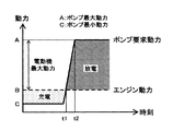
- FIG. 10 is an explanatory view of the minimum value related to the reference value of the engine target power. It is preferable that the minimum value of the reference value (engine target power) in the reference power calculation table 31 be defined by "maximum power of hydraulic pump 3-maximum power of motor / generator 2". Assuming that this value is the minimum value of the reference value, even if the pump required power sharply increases as shown in FIG. 10, the pump required power can be secured without changing the engine power, so the combustion situation of the engine 1 is deteriorated. There is no risk that the operability of the hydraulic equipment will be impaired. In addition, when a pump request
- the minimum value of the engine target power can also be determined according to "the response of the motor / generator 2."
- the power change speed “(A-B) / (t2-t1)” defined by the time “t2-t1" from engine power point B to reaching pump maximum power point A.
- the point B may be designed so that the speed of the motor / generator 2 is less than or equal to the maximum power change rate of the motor / generator 2.
- the power change speed indicates the amount of change in power per unit time, and indicates the output responsiveness of the engine 1, the generator / motor 2, and the like.
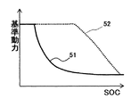
- FIG. 11 is a diagram showing another example of the reference power calculation table 31.
- the reference value of the target power of the engine 1 is lowered again. At that time, repetition of charge / discharge (hunting) may occur due to switching of the control target value.
- the reference power when the SOC decreases, the reference power is increased according to the solid line 51, and when the SOC is increased, the reference power is reduced according to the dotted line 52.
- hunting can be prevented.
- the power speed calculator 25 adopts a configuration using a first order low pass filter.
- the time constant T of the low pass filter is determined according to the SOC calculated by the remaining charge amount calculation unit 21.
- the time constant calculation table 32 shown in FIG. 9 is used for this calculation.
- the time constant calculation table 32 has the horizontal axis representing the SOC input to the change speed calculation unit 26, and has the vertical axis representing the time constant T output from the change speed calculation unit 26.
- the time constant T is set large when the remaining charge amount is large (the SOC is high), and the time constant T is set small when the remaining charge amount is small (the SOC is low).
- the leveling power calculation unit 27 is a first-order low-pass filter, and its time constant T changes according to the output calculated by the change speed calculation unit 26.
- T time constant
- a value obtained by leveling the pump request power is calculated as the output of the power speed calculation unit 25.
- the time constant T takes a large value when the state of charge is large (the SOC is high), and the output of the power speed calculation unit 25 corresponds to the change speed of the pump request power. It will stand up very slowly. For this reason, even if the pump required power rises sharply, the engine target power hardly changes from the reference power calculated by the reference power calculator 24. Thus, the engine 1 can maintain a stable combustion state.
- the minimum value (minimum time constant) of the time constant T determined by the time constant calculation table 32 (the change speed calculation unit 26) defines the maximum value of the power change speed of the engine. It is necessary to design the frequency region passing through the low pass filter at the constant T in such a range that the fuel efficiency of the engine and the transient response characteristic of the exhaust gas are not deteriorated.
- the gain K of the low-pass filter used in the leveling power calculation unit 27 is also a parameter for determining the rate of change of the engine target power. In the present embodiment, although the gain K is simplified to be a constant value, the value of the gain K may be changed according to the SOC as in the time constant T.
- a first-order low-pass filter is used for the leveling power calculator 27, the method of realizing the controller is of course not limited to this example.
- "changing the time constant when using a first-order low-pass filter” means “changing the number of data points when using moving average” or "using a rate limiter. Change the rate of change in the case.
- a "high-order low-pass filter” may be used. In this case, parameters for changing the cutoff frequency are to be changed.
- the power change speed of the motor / generator 2 is faster than the power change speed of the engine 1, and the power actually output by the motor / generator 2 instantaneously matches the "assist power command". For this reason, by adopting the configuration as described above, the power actually output by the engine 1 becomes equal to "pump power-assist power command". That is, although the power of the engine 1 is not directly controlled in the present embodiment, the power of the engine 1 can indirectly follow the target power calculated by the target power calculator 23.
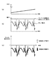
- FIG. 12 is a diagram showing changes in the SOC, the pump required power, the engine target power, and the assist power command in the case where the SOC is sufficient (for example, at the start of work the day after night charge etc.).
- the reference value of the engine target power starts from the minimum value at the SOC of time zero.
- the time constant T determined by the time constant calculation table 31 becomes the maximum value. For this reason, the change speed of the engine target power continues to take a value close to the reference value without following that of the pump power.
- FIG. 13 shows the SOC, the pump required power, the engine target power and the assist target when the SOC decreases near the predetermined level Sc (value greater than S1 and less than S2) indicated by the broken line in FIG. It is a figure which shows the change of motive power.
- the reference power calculated by the reference power calculation unit 24 has a value somewhat higher than that in the first case according to the decrease in SOC, and the value of the time constant T determined by the change speed calculation unit 26 is also It is smaller than the previous case.
- the engine target power is adjusted to be approximately the median (for example, moving average) of the pump required power or a value slightly higher than the median. It is preferable to keep the In this way, since the engine target power takes the median value of the pump required power, the assist power command of the motor / generator 2 calculated by "pump required power-engine target power" is shown in FIG. 13 (c). Repeat charging and discharging. As a result, the power of the engine 1 can be prevented from changing sharply, and the SOC can be kept at a constant level, so that it is possible to avoid the situation where the motor / generator 2 can not assist the engine 1. Further, setting the engine target power higher than the median value of the pump required power has the effect of preventing the SOC from being reduced due to the energy loss associated with charge and discharge.
- the engine target power is adjusted to be approximately the median (for example, moving average) of the pump required power or a value slightly higher than the median.
- FIG. 14 is a diagram showing changes in the SOC, the pump required power, the engine target power and the assist target power when the SOC is less than S1.
- the reference power of the engine 1 calculated by the reference power calculation unit 24 takes a value higher than the maximum value of the engine power.
- the reference power is maintained until the SOC recovers to a certain value because the transition to the dotted line 52 is made.
- the SOC threshold (S1) under the conditions as shown in FIG. 14 based on the change profile of the pump required power in the construction machine to which the SOC is applied.
- FIG. 15 is a simplified explanatory view of how to determine the engine target power when the SOC is low.
- the reference power of the engine target power takes a value higher than the maximum power line of the engine 1 as shown in FIG.
- the operation performed by the low pass filter corresponds to the change 91 with respect to the reference power.
- the change 91 in FIG. 15 is an example for making the description easy to understand, and the degree is not limited to that illustrated.
- the engine target power (the reference power calculation) generated in consideration of the change 91 (the output of the power speed calculation unit 25)
- the sum of the outputs of the unit 24 and the power speed calculating unit 25) is also always higher than the maximum power line of the engine 1.
- the final engine target power (the output of the engine target power calculation unit 23A) is limited to the maximum power and continues to take that value.
- the assist power command to the motor / generator 2 is defined by the value of "maximum engine power-pump required power" and is always given as "power generation request". to continue.
- control such as limitation of the pump required power is required.
- the change of the target power of the engine becomes sufficiently gentle with respect to the change speed of the pump required power.
- the assist power command assistant target power
- quick power assistance is realized with the high response motor / generator 2, and the engine 1 and the motor / generator 2 It can meet the pump power requirements.
- the motive power of the engine 1 whose response is slower than that of the motor / generator 2 changes gently.
- the pump required power sharply decreases, the surplus of the engine power is used for the power generation, so that the energy generated by the engine 1 can be used without waste.
- the change speed of the engine power is set relatively small, and the engine target power is relatively large (high In the output region, the change speed of the engine power is set relatively large.
- the above operation and effects are achieved by utilizing the configuration in which the change speed of the engine power is changed based on the SOC and the pump required power, but depending on the magnitude of the engine target power Setting the limit value of the change speed of the engine power, and changing the set value according to the magnitude of the engine target power (that is, the limit value of the change speed of the engine power is set larger as the engine target power increases.
- the limit value of the change speed of the engine power that is, the limit value of the change speed of the engine power is set larger as the engine target power increases.
- the engine target rotational speed calculation unit 35 The specific calculation method of the engine target speed in FIG. 3) was not particularly mentioned.
- the target engine speed is preferably calculated on the basis of engine characteristic data indicating the relationship between the amount of exhaust gas components such as nitrogen oxides and the fuel efficiency, and the engine speed and torque. Then, next, a preferred calculation example of the target rotational speed in the engine target rotational speed calculation unit 35 will be described.
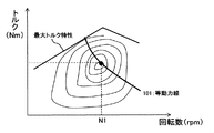
- FIG. 16 is a view showing a fuel consumption table used by the engine target speed computing unit 35 according to the third embodiment of the present invention.
- the equal fuel consumption table shown in this figure is a table format representing engine characteristic data indicating the fuel consumption of the engine at a predetermined rotational speed and torque, with the horizontal axis representing engine rotational speed and the vertical axis representing engine torque.
- the fuel consumption characteristic of the engine 1 is represented by plotting the combinations of revolutions and torques with equal fuel consumption by contour lines on a two-dimensional plane.
- the engine target speed calculation unit 35 described above selects a plurality of combinations of torque and rotation speed that can output the engine target power.
- One combination (or one combination closest to the desired fuel consumption) that can achieve the desired fuel consumption is extracted, and the rotation speed related to the one combination is output as the target rotation speed.
- the engine power is the product of torque and rotational speed, and the combination of torque and rotational speed that can achieve a predetermined engine target power can be drawn as a curve (equal power line 101) on the equal fuel consumption table. Therefore, as shown in FIG.
- an equal power line 101 is drawn based on the input value from engine target power calculation unit 23, and the number of revolutions related to the best operating point of fuel efficiency from the point on equal power line 101 (N1 ) May be output as the target rotational speed.
- the output of the engine target speed calculator 35 is used as the target speed of the engine 1.
- the “equivalent emission gas table” is used in which the engine characteristic data indicating the amount of exhaust gas components such as nitrogen oxides at a predetermined rotation speed and torque is represented in a table format. It is also possible to determine the target speed.
- the horizontal axis is the rotational speed
- the vertical axis is the torque
- steady-state characteristics for example, the amount of each exhaust gas component
- the characteristic of the exhaust gas component of the engine 1 is represented by plotting the combinations of equal rotational speeds and torques with contour lines.
- this equal emission gas table is used in the same manner as the above-mentioned equal fuel consumption table, so the amount of substances having environmental load in the steady state exhaust gas can be optimized, so the effect of exhaust gas purification by load equalization can be further enhanced. It can be improved. Furthermore, the engine 1 can also be driven at an operation point that can realize low fuel consumption and low exhaust gas by using the above-mentioned "equivalent fuel consumption table” and "equal exhaust gas table” in combination. In addition to the fuel consumption and the exhaust gas described above, the target rotational speed may be determined based on other engine characteristic data.
- the engine 1 can be operated at a preferable operating speed in terms of fuel consumption and exhaust gas without the operator setting the engine speed successively. This not only realizes energy saving and reduction of substances having environmental load in exhaust gas, but also leads to reduction of the workload on the operator.
- the configuration of engine target power calculation unit 23A shown in FIG. 9 is an effective configuration when power storage device 10 utilizes a device such as a lithium ion battery having a high energy density and capable of continuously utilizing a high output. is there.
- a storage device which can only supply energy instantaneously like a capacitor, if the reference power is determined according to the SOC as shown in FIG. There is a risk that the engine may stall. Therefore, a configuration that is effective when a capacitor or the like is used as power storage device 10 will be described next with reference to FIG.
- FIG. 17 is a diagram showing an example of contents of arithmetic processing in the engine target power arithmetic unit 23B.
- the engine target power calculation unit 23B shown in this figure includes a reference power calculation unit 24B and a power speed calculation unit 25B.
- the reference power calculation unit 24B is a part configured of the low pass filter 111, and executes the process of generating the reference power by applying the low pass filter 111 to the pump required power output from the pump power calculation unit 22.
- Kl is a gain
- Tl is a value independent of SOC.
- the power speed calculation unit 25B is a part that executes processing for defining the fluctuation speed and fluctuation range of the engine target power by applying the high-pass filter 112 to the pump required power output from the pump power calculation unit 22.
- Kh in the figure is a gain.
- the power speed calculation unit 25 B includes a time constant calculation table 113 for defining the time constant Th used by the high pass filter 112 according to the SOC output from the remaining charge amount calculation unit 21. Similar to the time constant calculation table 32 of FIG. 9, in the time constant calculation table 113, the time constant Th is set to be smaller as the remaining amount of charge is higher (the SOC is higher), and the time is smaller as the remaining amount of battery is stored The constant Th is set large.
- the time constant Th set in this way when the SOC is high, the time constant of the high pass filter 112 becomes small, and the high frequency components to be transmitted are reduced.
- the remaining charge amount when the remaining charge amount is large, the fluctuation range of the engine target power decreases, and the power fluctuation borne by the motor / generator 2 increases.
- the time constant of the high pass filter 112 increases, so the high frequency components to be passed increase. If the change of the time constant of the high pass filter 112 is large, the engine target power may increase sharply. In order to avoid this, in the time constant calculation table 113, it is preferable to make the amount of change of the time constant ( ⁇ T in FIG. 17) accompanying the change of SOC relatively small.
- the engine target power calculation unit 23B configured as described above, the sum of the output values of the reference power calculation unit 24B and the power speed calculation unit 25B is output as the final engine target power.
- the reference power is calculated regardless of the SOC of the storage device 10 by the reference power calculation unit 24B
- the engine target power finally output from the engine target power calculation unit 23B is operated by the power speed calculation unit 25B. It will be set larger as the SOC decreases.
- the behavior in this configuration is basically the same as that shown in FIG. 13 even if the SOC of power storage device 10 changes. Therefore, if engine target power calculation unit 23B is configured as described above, even if a capacitor is used for power storage device 10, it is possible to avoid the occurrence of engine stall when engine power decreases.
- the engine target power is controlled to increase as the SOC of power storage device 10 decreases.
- a limit value of engine target power is set, and the limit value is set according to the decrease of SOC. It may be controlled to be larger. That is, not the engine target power but the "limit value of the engine target power" may be controlled according to the SOC.
- the hydraulic shovel has been described as an example, the other hybrid type in which the hydraulic pump for supplying the hydraulic fluid to the hydraulic actuator is driven by the engine and the motor / generator. It goes without saying that the present invention is also applicable to construction machines.
Abstract
Description
図1は本発明の実施の形態に係るハイブリッド式油圧ショベルにおける油圧駆動制御装置の概略構成図である。この図に示す油圧駆動制御装置は、エンジン1と、エンジン1の燃料噴射量を調整するガバナ7と、エンジン1の実回転数を検出する回転数センサ(実回転数検出手段)6と、エンジン1の出力軸に機械的に連結され、エンジン1との間でトルクの伝達を行う電動・発電機2と、エンジン1及び電動・発電機2の出力軸に機械的に連結され、エンジン1及び電動・発電機2の少なくとも一方によって駆動される可変容量型油圧ポンプ3(以下、単に「油圧ポンプ3」と称することがある)及びパイロットポンプ32と、油圧ポンプ3から吐出される圧油によって駆動される油圧アクチュエータ5と、パイロットポンプ32から吐出される圧油を減圧してバルブ装置4に出力することで油圧アクチュエータ5を制御するための操作レバー(操作装置)16と、主に電動・発電機2を駆動するための電力を蓄えるための蓄電装置(蓄電手段)10と、油圧ポンプ3の容量を調節するポンプ容量調節装置(ポンプ容量調節手段)14と、ポンプ容量調節装置14を制御する電磁比例弁15と、電動・発電機2の制御とともに、電動・発電機2と蓄電装置10間での電力の授受を制御するインバータ(電力変換装置)9と、エンジン1、電動・発電機2及び油圧ポンプ3をはじめとする各種装置を制御するためのコントローラ(制御手段)8とを備えている。 Hereinafter, embodiments of the present invention will be described using the drawings.
FIG. 1 is a schematic configuration diagram of a hydraulic drive control device in a hybrid hydraulic shovel according to an embodiment of the present invention. The hydraulic drive control device shown in this figure includes an
2 電動・発電機
3 油圧ポンプ
5 油圧アクチュエータ
9 インバータ
10 蓄電装置
16 操作レバー
21 蓄電残量演算部
22 ポンプ動力演算部
23,23A,23B エンジン目標動力演算部
24,24B 基準動力演算部
25,25B 動作速度演算部
26 変化速度演算部
27 平準動力演算部
28 アシスト動力制御部
31 基準動力演算テーブル
32 時定数演算テーブル
34 電動・発電機目標動力演算部
35 エンジン目標回転数演算部
36 エンジン目標回転数制御部
111 ローパスフィルタ
112 ハイパスフィルタ
113 時定数演算テーブル DESCRIPTION OF
Claims (6)
- エンジンと、
前記エンジンとの間でトルクの伝達を行う電動・発電機と、
前記エンジン及び前記電動・発電機の少なくとも一方によって駆動される油圧ポンプと、
当該油圧ポンプから吐出される圧油によって駆動される油圧アクチュエータと、
前記電動・発電機に電力を供給するための蓄電装置と、
前記蓄電装置の蓄電残量に基づいて前記エンジンの目標動力を設定し、当該エンジンの目標動力と前記ポンプの要求動力に基づいて前記電動・発電機の目標動力を設定する制御手段とを備え、
前記エンジンの目標動力は、前記蓄電装置の蓄電残量が減少するに応じて単調増加するように設定されていることを特徴とするハイブリッド式建設機械。 With the engine,
A motor / generator that transmits torque between the engine and the engine;
A hydraulic pump driven by at least one of the engine and the motor / generator;
A hydraulic actuator driven by pressure oil discharged from the hydraulic pump;
A storage device for supplying power to the motor / generator;
Control means for setting a target power of the engine based on the remaining charge of the power storage device, and setting a target power of the motor / generator based on the target power of the engine and the required power of the pump.
A hybrid type construction machine, wherein a target power of the engine is set to monotonously increase as the remaining charge amount of the power storage device decreases. - 請求項1に記載のハイブリッド式建設機械において、
前記制御手段は、前記蓄電残量が減少するにつれて、前記エンジンの目標動力の変化速度を大きく設定することを特徴とするハイブリッド式建設機械。 In the hybrid construction machine according to claim 1,
The said control means sets the change speed of the target motive power of the said engine large as the said electrical storage residual amount reduces, The hybrid type construction machine characterized by the above-mentioned. - 請求項1又は2に記載のハイブリッド式建設機械において、
前記制御手段は、前記エンジンの目標動力が増加するにつれて、前記エンジンの動力の変化速度の制限値を大きく設定することを特徴とするハイブリッド式建設機械。 The hybrid construction machine according to claim 1 or 2
A hybrid type construction machine, wherein the control means sets a limit value of change speed of the power of the engine to be large as the target power of the engine increases. - 請求項1から3のいずれかに記載のハイブリッド式建設機械において、
前記制御手段は、前記蓄電残量が第1設定値以下の値に達すると、前記エンジンの目標動力を前記エンジンの最大動力に設定することを特徴とするハイブリッド式建設機械。 The hybrid construction machine according to any one of claims 1 to 3
The said control means sets the target motive power of the said engine to the maximum motive power of the said engine, when the said electrical storage residual amount reaches the value below the 1st setting value. - 請求項1から4のいずれかに記載のハイブリッド式建設機械において、
前記制御手段は、前記第1設定値より大きい第2設定値以上の値に前記蓄電残量が達すると、前記エンジンの目標動力を前記油圧ポンプの最小動力より小さい値に設定することを特徴とするハイブリッド式建設機械。 The hybrid construction machine according to any one of claims 1 to 4,
The control means sets the target power of the engine to a value smaller than the minimum power of the hydraulic pump when the remaining amount of power reaches a value equal to or greater than a second set value larger than the first set value. Hybrid construction machine. - 請求項1から5のいずれかに記載のハイブリッド式建設機械において、
前記制御手段は、前記エンジンの燃費及び排ガス量の少なくとも一方と当該エンジンの回転数及びトルクとの関係を示すエンジン特性データと、前記エンジンの目標動力とに基づいて、前記エンジンの目標回転数を設定することを特徴とするハイブリッド式建設機械。 The hybrid construction machine according to any one of claims 1 to 5,
The control means determines a target rotational speed of the engine based on engine characteristic data indicating a relationship between at least one of the fuel efficiency and the exhaust gas amount of the engine and the rotational speed and torque of the engine, and target power of the engine. A hybrid construction machine characterized by setting.
Priority Applications (5)
| Application Number | Priority Date | Filing Date | Title |
|---|---|---|---|
| US14/400,947 US9487932B2 (en) | 2012-05-14 | 2013-05-10 | Hybrid construction machine |
| EP13790109.6A EP2851475B1 (en) | 2012-05-14 | 2013-05-10 | Hybrid construction machinery |
| JP2014515600A JP5952901B2 (en) | 2012-05-14 | 2013-05-10 | Hybrid construction machine |
| CN201380025106.0A CN104302847B (en) | 2012-05-14 | 2013-05-10 | Hybrid construction machine |
| KR1020147030391A KR101716943B1 (en) | 2012-05-14 | 2013-05-10 | Hybrid construction machinery |
Applications Claiming Priority (2)
| Application Number | Priority Date | Filing Date | Title |
|---|---|---|---|
| JP2012-110875 | 2012-05-14 | ||
| JP2012110875 | 2012-05-14 |
Publications (1)
| Publication Number | Publication Date |
|---|---|
| WO2013172276A1 true WO2013172276A1 (en) | 2013-11-21 |
Family
ID=49583681
Family Applications (1)
| Application Number | Title | Priority Date | Filing Date |
|---|---|---|---|
| PCT/JP2013/063199 WO2013172276A1 (en) | 2012-05-14 | 2013-05-10 | Hybrid construction machinery |
Country Status (6)
| Country | Link |
|---|---|
| US (1) | US9487932B2 (en) |
| EP (1) | EP2851475B1 (en) |
| JP (1) | JP5952901B2 (en) |
| KR (1) | KR101716943B1 (en) |
| CN (1) | CN104302847B (en) |
| WO (1) | WO2013172276A1 (en) |
Cited By (6)
| Publication number | Priority date | Publication date | Assignee | Title |
|---|---|---|---|---|
| JP2014051795A (en) * | 2012-09-06 | 2014-03-20 | Kobelco Contstruction Machinery Ltd | Power control device for hybrid construction machine |
| JP2016159785A (en) * | 2015-03-02 | 2016-09-05 | 日立建機株式会社 | Hybrid work machine |
| JP2017206865A (en) * | 2016-05-18 | 2017-11-24 | 日立建機株式会社 | Construction machine |
| EP3103693A4 (en) * | 2014-02-03 | 2017-12-20 | Hitachi Construction Machinery Co., Ltd. | Hybrid construction machine |
| WO2018061166A1 (en) * | 2016-09-29 | 2018-04-05 | 日立建機株式会社 | Hybrid construction machine |
| CN115324149A (en) * | 2022-06-30 | 2022-11-11 | 三一重机有限公司 | Hydraulic pump control method, hydraulic pump control device and working machine |
Families Citing this family (11)
| Publication number | Priority date | Publication date | Assignee | Title |
|---|---|---|---|---|
| JP6014463B2 (en) * | 2012-11-07 | 2016-10-25 | 日立建機株式会社 | Work vehicle |
| JP5303061B1 (en) * | 2012-11-20 | 2013-10-02 | 株式会社小松製作所 | Engine control device and construction machine |
| JP6401241B2 (en) * | 2014-03-06 | 2018-10-10 | 住友建機株式会社 | Excavator |
| KR101921435B1 (en) * | 2014-10-14 | 2018-11-22 | 히다찌 겐끼 가부시키가이샤 | Hybrid construction machinery |
| EP3255285B1 (en) * | 2015-01-08 | 2020-11-11 | Volvo Construction Equipment AB | Drive control method of hydraulic actuator of construction machine |
| JP6232007B2 (en) * | 2015-03-02 | 2017-11-15 | 株式会社日立建機ティエラ | Hybrid work machine |
| CN105172617B (en) * | 2015-09-07 | 2017-12-22 | 吉林大学 | Front-rear axle independently drives loading machine structure and torque dynamic allocation method |
| JP6419063B2 (en) * | 2015-12-24 | 2018-11-07 | 日立建機株式会社 | Hybrid work machine |
| JP6647963B2 (en) * | 2016-05-18 | 2020-02-14 | 日立建機株式会社 | Construction machinery |
| RU2748345C1 (en) * | 2017-12-15 | 2021-05-24 | Ниссан Мотор Ко., Лтд. | Method and device for hybrid vehicle engine control |
| CN113525345B (en) * | 2021-07-30 | 2022-09-06 | 三一汽车起重机械有限公司 | Hybrid power engineering machinery limping control method and device and crane |
Citations (5)
| Publication number | Priority date | Publication date | Assignee | Title |
|---|---|---|---|---|
| JP2003009308A (en) | 2001-06-22 | 2003-01-10 | Kobelco Contstruction Machinery Ltd | Work machine |
| JP4512283B2 (en) | 2001-03-12 | 2010-07-28 | 株式会社小松製作所 | Hybrid construction machine |
| JP4633813B2 (en) | 2008-03-12 | 2011-02-16 | 住友重機械工業株式会社 | Construction machine control method |
| JP2011190072A (en) * | 2010-03-16 | 2011-09-29 | Kobe Steel Ltd | Working vehicle |
| WO2012050135A1 (en) * | 2010-10-15 | 2012-04-19 | 日立建機株式会社 | Hybrid construction machine |
Family Cites Families (6)
| Publication number | Priority date | Publication date | Assignee | Title |
|---|---|---|---|---|
| JP3833573B2 (en) * | 2002-06-06 | 2006-10-11 | 新キャタピラー三菱株式会社 | Hybrid construction machine |
| JP5064160B2 (en) * | 2007-09-19 | 2012-10-31 | 株式会社小松製作所 | Engine control device |
| JP5149826B2 (en) * | 2009-01-29 | 2013-02-20 | 住友重機械工業株式会社 | Hybrid work machine and servo control system |
| JP2012017677A (en) | 2010-07-07 | 2012-01-26 | Caterpillar Sarl | Device for control of hybrid construction machine |
| JP5665874B2 (en) * | 2010-10-06 | 2015-02-04 | 住友重機械工業株式会社 | Hybrid work machine and control method thereof |
| JP6019956B2 (en) * | 2012-09-06 | 2016-11-02 | コベルコ建機株式会社 | Power control device for hybrid construction machinery |
-
2013
- 2013-05-10 WO PCT/JP2013/063199 patent/WO2013172276A1/en active Application Filing
- 2013-05-10 JP JP2014515600A patent/JP5952901B2/en not_active Expired - Fee Related
- 2013-05-10 KR KR1020147030391A patent/KR101716943B1/en active IP Right Grant
- 2013-05-10 US US14/400,947 patent/US9487932B2/en active Active
- 2013-05-10 CN CN201380025106.0A patent/CN104302847B/en active Active
- 2013-05-10 EP EP13790109.6A patent/EP2851475B1/en active Active
Patent Citations (5)
| Publication number | Priority date | Publication date | Assignee | Title |
|---|---|---|---|---|
| JP4512283B2 (en) | 2001-03-12 | 2010-07-28 | 株式会社小松製作所 | Hybrid construction machine |
| JP2003009308A (en) | 2001-06-22 | 2003-01-10 | Kobelco Contstruction Machinery Ltd | Work machine |
| JP4633813B2 (en) | 2008-03-12 | 2011-02-16 | 住友重機械工業株式会社 | Construction machine control method |
| JP2011190072A (en) * | 2010-03-16 | 2011-09-29 | Kobe Steel Ltd | Working vehicle |
| WO2012050135A1 (en) * | 2010-10-15 | 2012-04-19 | 日立建機株式会社 | Hybrid construction machine |
Cited By (9)
| Publication number | Priority date | Publication date | Assignee | Title |
|---|---|---|---|---|
| JP2014051795A (en) * | 2012-09-06 | 2014-03-20 | Kobelco Contstruction Machinery Ltd | Power control device for hybrid construction machine |
| EP3103693A4 (en) * | 2014-02-03 | 2017-12-20 | Hitachi Construction Machinery Co., Ltd. | Hybrid construction machine |
| JP2016159785A (en) * | 2015-03-02 | 2016-09-05 | 日立建機株式会社 | Hybrid work machine |
| WO2016139853A1 (en) * | 2015-03-02 | 2016-09-09 | 日立建機株式会社 | Hybrid work machine |
| JP2017206865A (en) * | 2016-05-18 | 2017-11-24 | 日立建機株式会社 | Construction machine |
| WO2018061166A1 (en) * | 2016-09-29 | 2018-04-05 | 日立建機株式会社 | Hybrid construction machine |
| US10668802B2 (en) | 2016-09-29 | 2020-06-02 | Hitachi Construction Machinery Co., Ltd. | Hybrid construction machine |
| CN115324149A (en) * | 2022-06-30 | 2022-11-11 | 三一重机有限公司 | Hydraulic pump control method, hydraulic pump control device and working machine |
| CN115324149B (en) * | 2022-06-30 | 2023-10-27 | 三一重机有限公司 | Hydraulic pump control method and device and working machine |
Also Published As
| Publication number | Publication date |
|---|---|
| US9487932B2 (en) | 2016-11-08 |
| CN104302847A (en) | 2015-01-21 |
| EP2851475A4 (en) | 2016-02-24 |
| KR101716943B1 (en) | 2017-03-15 |
| JPWO2013172276A1 (en) | 2016-01-12 |
| CN104302847B (en) | 2016-10-12 |
| US20150144408A1 (en) | 2015-05-28 |
| JP5952901B2 (en) | 2016-07-13 |
| EP2851475A1 (en) | 2015-03-25 |
| KR20150001785A (en) | 2015-01-06 |
| EP2851475B1 (en) | 2018-07-11 |
Similar Documents
| Publication | Publication Date | Title |
|---|---|---|
| WO2013172276A1 (en) | Hybrid construction machinery | |
| JP5356436B2 (en) | Construction machine control equipment | |
| JP5916763B2 (en) | Construction machine control equipment | |
| JP5715047B2 (en) | Hybrid work machine | |
| JP5974014B2 (en) | Hybrid drive hydraulic work machine | |
| CN103180519B (en) | Hybrid construction machine | |
| KR101776543B1 (en) | Work machine | |
| WO2012032909A1 (en) | Hybrid construction machine | |
| KR101804433B1 (en) | Construction machine | |
| JP2007262978A (en) | Output control device for hybrid working machine and output control method for hybrid working machine | |
| JP6382023B2 (en) | Power control apparatus and hybrid construction machine equipped with the same | |
| CN107923148B (en) | Hybrid working machine | |
| WO2014087978A1 (en) | Work machine | |
| WO2020044921A1 (en) | Hybrid construction machine | |
| KR20150082291A (en) | Hybrid shovel and hybrid shovel control method |
Legal Events
| Date | Code | Title | Description |
|---|---|---|---|
| 121 | Ep: the epo has been informed by wipo that ep was designated in this application |
Ref document number: 13790109 Country of ref document: EP Kind code of ref document: A1 |
|
| ENP | Entry into the national phase |
Ref document number: 2014515600 Country of ref document: JP Kind code of ref document: A |
|
| ENP | Entry into the national phase |
Ref document number: 20147030391 Country of ref document: KR Kind code of ref document: A |
|
| WWE | Wipo information: entry into national phase |
Ref document number: 2013790109 Country of ref document: EP |
|
| WWE | Wipo information: entry into national phase |
Ref document number: 14400947 Country of ref document: US |
|
| NENP | Non-entry into the national phase |
Ref country code: DE |