WO2013161443A1 - X線ct装置及び画像再構成方法 - Google Patents
X線ct装置及び画像再構成方法 Download PDFInfo
- Publication number
- WO2013161443A1 WO2013161443A1 PCT/JP2013/057583 JP2013057583W WO2013161443A1 WO 2013161443 A1 WO2013161443 A1 WO 2013161443A1 JP 2013057583 W JP2013057583 W JP 2013057583W WO 2013161443 A1 WO2013161443 A1 WO 2013161443A1
- Authority
- WO
- WIPO (PCT)
- Prior art keywords
- phase width
- ray
- pixel
- width
- backprojection
- Prior art date
- Legal status (The legal status is an assumption and is not a legal conclusion. Google has not performed a legal analysis and makes no representation as to the accuracy of the status listed.)
- Ceased
Links
Images


Classifications
-
- G—PHYSICS
- G06—COMPUTING OR CALCULATING; COUNTING
- G06T—IMAGE DATA PROCESSING OR GENERATION, IN GENERAL
- G06T12/00—Tomographic reconstruction from projections
- G06T12/20—Inverse problem, i.e. transformations from projection space into object space
-
- G—PHYSICS
- G06—COMPUTING OR CALCULATING; COUNTING
- G06T—IMAGE DATA PROCESSING OR GENERATION, IN GENERAL
- G06T7/00—Image analysis
- G06T7/0002—Inspection of images, e.g. flaw detection
- G06T7/0012—Biomedical image inspection
-
- A—HUMAN NECESSITIES
- A61—MEDICAL OR VETERINARY SCIENCE; HYGIENE
- A61B—DIAGNOSIS; SURGERY; IDENTIFICATION
- A61B6/00—Apparatus or devices for radiation diagnosis; Apparatus or devices for radiation diagnosis combined with radiation therapy equipment
- A61B6/02—Arrangements for diagnosis sequentially in different planes; Stereoscopic radiation diagnosis
- A61B6/03—Computed tomography [CT]
- A61B6/032—Transmission computed tomography [CT]
-
- A—HUMAN NECESSITIES
- A61—MEDICAL OR VETERINARY SCIENCE; HYGIENE
- A61B—DIAGNOSIS; SURGERY; IDENTIFICATION
- A61B6/00—Apparatus or devices for radiation diagnosis; Apparatus or devices for radiation diagnosis combined with radiation therapy equipment
- A61B6/52—Devices using data or image processing specially adapted for radiation diagnosis
- A61B6/5205—Devices using data or image processing specially adapted for radiation diagnosis involving processing of raw data to produce diagnostic data
-
- G—PHYSICS
- G06—COMPUTING OR CALCULATING; COUNTING
- G06T—IMAGE DATA PROCESSING OR GENERATION, IN GENERAL
- G06T2207/00—Indexing scheme for image analysis or image enhancement
- G06T2207/10—Image acquisition modality
- G06T2207/10072—Tomographic images
- G06T2207/10081—Computed x-ray tomography [CT]
-
- G—PHYSICS
- G06—COMPUTING OR CALCULATING; COUNTING
- G06T—IMAGE DATA PROCESSING OR GENERATION, IN GENERAL
- G06T2211/00—Image generation
- G06T2211/40—Computed tomography
- G06T2211/412—Dynamic
Definitions
- the present invention provides an X-ray CT apparatus that irradiates a subject with X-rays, measures X-rays transmitted through the subject with an X-ray detector, and reconstructs measurement data from multiple directions to obtain a reconstructed image of the subject Etc.
- the present invention relates to an X-ray CT apparatus that can control the noise characteristics of a reconstructed image.
- backprojection phase width the wider the angular width of projection data used for reconstruction (hereinafter referred to as “backprojection phase width”), the smaller the amount of noise in the reconstructed image. Conversely, the smaller the backprojection phase width, the greater the amount of noise in the reconstructed image.
- Patent Document 1 discloses a method of performing reconstruction using the same backprojection phase width regardless of the image position in order to perform reconstruction processing at high speed while avoiding noise unevenness in the reconstructed image. ing. Specifically, the narrowest backprojection phase width that can be used in the image is used. When a constant backprojection phase width is used regardless of the image position as in Patent Document 1, the backprojection phase width becomes a constant value without being affected by the reconstruction slice position or imaging FOV. Is stable. Furthermore, since the backprojection phase width is narrowed, the time resolution is increased. On the other hand, when the projection data to be used is limited, there is a problem that the back projection phase width becomes narrow and noise increases as a whole. Further, when the back projection phase width is wide, there is a problem that an artifact is generated by extrapolation.
- Patent Document 2 calculates a normalized weight based on a cone angle-dependent weight and uses it for back projection, thereby allowing more projection data to be reconstructed. Has been proposed. With the method of Patent Document 2, since more projection data can be used, an image with less noise can be obtained. Furthermore, extrapolation errors can be reduced by using weights depending on the cone angle.
- the head may be diagnosed based on the difference between the right and left brain.
- the noise unevenness on the axial image causes striped noise unevenness in the MPR image, which similarly hinders the diagnosis of a lesion.
- Patent Document 1 When the fixed backprojection phase width is used regardless of the FOV size as in the method of Patent Document 1, the data use efficiency is relatively low. Therefore, there is a problem that the noise of the generated reconstructed image is increased and the exposure dose when obtaining a desired image quality is increased. In addition, in Patent Document 1, when a constant backprojection phase width according to the FOV size is used, the amount of noise and time resolution (blurring due to motion and motion artifacts) may change greatly according to the FOV size. Not desirable for diagnosis.
- the present invention has been made in view of the above-described problems, and its purpose is to generate a reconstructed image capable of appropriate image diagnosis that matches the characteristics of a part (particularly, a symmetrical part). To provide an X-ray CT system.
- the first invention for achieving the above-described object is an X-ray generator that irradiates X-rays from around a subject, an X-ray detector that detects X-rays that pass through the subject, and the X-ray detector.
- a data collection device that collects data detected by the computer, and a calculation device that inputs the data collected by the data collection device to create projection data and reconstructs a CT image using the projection data.
- the arithmetic unit calculates a back projection phase width in each pixel based on a distance from a reference position defined by one or more reference points on the axial plane, and calculates the back projection phase width in each pixel.
- the X-ray CT apparatus uses the view weight to calculate a view weight and reconstructs the CT image.
- an X-ray generator that emits X-rays from around a subject, an X-ray detector that detects X-rays that pass through the subject, and data detected by the X-ray detector are collected.
- a data collection device and a calculation device that inputs data collected by the data collection device to create projection data and reconstructs a CT image using the projection data, and the calculation device includes an axial plane.
- the calculation device includes an axial plane.
- an X-ray CT apparatus or the like that generates a reconstructed image capable of appropriate image diagnosis that matches the characteristics of a part (particularly a symmetrical part).
- a sinogram showing the smallest complete data set Diagram showing shape of prior art view weight function The figure which shows the relationship between the back projection phase width and image noise in the view weight of a prior art
- Flow chart showing the flow of processing of the X-ray CT apparatus when the reference position is one reference point and the reference point is at the orbital center position
- Explanatory drawing of the first method when the reference position is one reference point and the reference point is located away from the orbiting center
- Explanatory drawing of the second method when the reference position is one reference point and the reference point is located away from the orbit
- the X-ray CT apparatus 1 is roughly composed of a scanner 10 and an operation unit 20.
- the scanner 10 includes a bed apparatus 101, an X-ray generation apparatus 102, an X-ray detection apparatus 103, a collimator apparatus 104, a high voltage generation apparatus 105, a data collection apparatus 106, a drive apparatus 107, and the like.
- the operation unit 20 includes a central control device 200, an input / output device 201, an arithmetic device 202, and the like.
- the operator inputs shooting conditions and reconstruction conditions via the input / output device 201.
- the imaging conditions are, for example, a bed feeding speed, a tube current, a tube voltage, an imaging range (slice position range), the number of imaging views per revolution, and the like.
- the reconstruction conditions are, for example, a region of interest, a CT image size (CT image size), a reconstruction filter function, and the like.
- the input / output device 201 includes a display device 211 that displays CT images and the like, an input device 212 such as a mouse, trackball, keyboard, and touch panel, a storage device 213 that stores data, and the like.
- the central control device 200 inputs shooting conditions and reconstruction conditions, and transmits a control signal necessary for shooting to each device included in the scanner 10.
- the collimator device 104 controls the position of the collimator based on the control signal.
- the high voltage generator 105 applies a tube voltage and a tube current to the X-ray generator 102 based on the control signal.
- the X-ray generator 102 electrons having energy corresponding to the applied tube voltage are emitted from the cathode, and the emitted electrons collide with the target (anode), so that X-rays 108 having energy corresponding to the electron energy are captured by the subject. 3 is irradiated.
- the driving device 107 circulates the gantry 100 on which the X-ray generation device 102, the X-ray detection device 103, and the like are mounted around the subject 3 based on the control signal.
- the couch device 101 controls the couch based on the control signal.
- the X-ray 108 irradiated from the X-ray generator 102 has an irradiation area limited by a collimator, is absorbed (attenuated) in accordance with the X-ray attenuation coefficient in each tissue in the subject 3, passes through the subject 3, and X-rays It is detected by an X-ray detector 103 arranged at a position facing the generator 102.
- the X-ray detection device 103 is arranged in a two-dimensional direction (a channel direction and a column direction orthogonal thereto) and a single-row detector composed of a plurality of detection elements arranged in a one-dimensional direction (channel direction).
- a multi-row detectors constituted by a plurality of detection elements.
- the detection elements are arranged in an arc shape in the circumferential direction.
- single-row detectors are arranged in a plurality of rows in the direction of the rotation axis, and a wider range than the single-row detector can be photographed at a time.
- the X-ray 108 detected by each detection element is converted into raw data. That is, the X-ray 108 detected by the X-ray detection device 103 is subjected to various data processing (conversion to digital data, LOG conversion, calibration, etc.) by the data collection device 106, and is loaded into the arithmetic device 202. Input as data.
- the X-ray generation device 102 and the X-ray detection device 103 facing each other rotate around the subject 3 (however, excluding positioning imaging), the X-ray generation device 102 moves from the periphery of the subject 3 to the X The line 108 will be irradiated. Further, the X-ray detection device 103 detects X-rays 108 that pass through the subject 3. That is, raw data is collected at discrete X-ray tube positions in the rotational direction (also referred to as opposing detector positions). The raw data acquisition unit at each X-ray tube position is a “view”.
- the X-ray CT apparatus 1 is a multi-slice CT using an X-ray detection apparatus 103 in which detection elements are arranged in a two-dimensional direction, and an X-ray detection in which the detection elements are arranged in one row, that is, in a one-dimensional direction (channel direction only) It is roughly divided into single slice CT using the apparatus 103.
- X-rays 108 that spread in a cone shape or a pyramid shape are emitted from an X-ray generation device 102 that is an X-ray source in accordance with the X-ray detection device 103.
- single slice CT X-rays 108 that radiate in a fan shape are emitted from the X-ray generator 102.
- the gantry 100 irradiates the X-ray 108 while circling around the subject 3 placed on the bed (except for positioning imaging).
- the distance that the bed travels relative to the imaging system during one rotation of the imaging system is defined as “bed movement speed” (mm / rotation).
- bed movement speed mm / rotation
- pitch the ratio of the detector element's rotation axis position to the circumferential axis width at which the bed moves relative to the imaging system during one rotation of the imaging system It is defined as “pitch”.
- beam pitch a ratio with respect to the total length in the rotation axis direction of the detector in which the bed advances relative to the imaging system during one rotation of the imaging system.
- the X-ray CT apparatus 1 generally captures about 1000 times per lap in the lap direction.
- Imaging modes in which the bed is fixed during imaging and the X-ray generator 102 circulates in a circular orbit around the subject 3 are axial scan, normal scan, conventional scan (hereinafter, unified as “axial scan”), etc. Called.
- axial scan normal scan
- conventional scan conventional scan
- step-and-shoot scanning or the like a photographing mode in which photographing is performed with the bed fixed and the bed is moved to the next photographing position.
- the imaging mode in which the bed moves continuously and the X-ray generator 102 circulates around the subject 3 in a spiral trajectory is unified into a spiral scan, a helical scan, and a spiral scan (hereinafter “spiral scan”). ) Etc.
- the bed apparatus 101 keeps the bed stationary while taking a picture.
- the couch device 101 translates the couch in the body axis direction of the subject 3 while taking a picture according to the speed of the couch feeding, which is one of the photographing conditions.
- the image at the position of the X-ray generator 102 (X-ray source) can be accurately reproduced by performing the filter-corrected two-dimensional backprojection.
- X-ray generator 102 X-ray source
- streak occurs at the position where the discontinuity occurs only with filter-corrected two-dimensional backprojection.
- shaped artifacts Therefore, the data obtained by the helical scan is corrected to circular orbit data by using data interpolation, and then the filter correction two-dimensional backprojection is performed.
- interpolation By using interpolation in this way, an image with reduced discontinuity can be obtained.
- the degree of artifact in this case depends on the degree of discontinuity in the X-ray source trajectory. That is, the degree of artifact varies depending on the moving speed of the subject.
- the computing device 202 includes a reconstruction computing device 221, an image processing device 222, and the like.
- the input / output device 201 includes an input device 212, a display device 211, a storage device 213, and the like.
- the reconstruction calculation device 221 inputs raw data collected by the data collection device, creates projection data, performs image reconstruction using the projection data, and generates a CT image.
- the reconstruction calculation device 221 stores the CT image in the storage device 213. Further, the reconstruction calculation device 221 displays the CT image on the display device 211. Alternatively, the image processing device 222 performs image processing on the CT image stored in the storage device 213, and displays the image after image processing on the display device 211.
- a method called “Feldkamp reconstruction method”, which is an extension of the two-dimensional reconstruction method used in single-slice CT, or a method using this method is mainly used.
- the Feldkamp method the inclination of the beam of the X-ray 108 in the body axis direction is accurately handled with respect to the data obtained by multi-slice CT, and the projection value is assigned to the pixel along the beam path. Therefore, at the time of back projection, projection data in an angle range in which the X-ray 108 is irradiated for each pixel can be used for back projection.
- reconstruction is performed using 180-degree data (half-scan data) and 180-360-degree data (extended half-scan data). It can be classified into a configuration, a reconstruction using 360 degree data (full scan data), and a reconstruction using data more than 360 degrees (overscan data).
- reconstruction using half-scan data has few components in the time direction of the projection data to be used, and the time resolution is high.
- an image is generated with a minimum amount of projection data, there is a relatively large amount of noise.
- an artifact is generated sensitively to the movement of the subject.
- Example of fan beam reconstruction I Image data, x, y, z: Reconstruction target pixel position (mm), L: Distance from the X-ray generator 102 (X-ray source) to the reconstruction target pixel (mm), ⁇ : Fan beam projection Angle (rad), W f (•): Fan beam view weight, ⁇ : Fan angle (rad), P f (•): Projection data, ⁇ : Detector array position (mm), g (•): Re A configuration filter.
- Example of parallel beam reconstruction I Image data, x, y, z: Reconstruction target pixel position (mm), W p (•): View weight for parallel beam, ⁇ : Parallel beam projection angle (rad), P p (•): Projection Data, t: parallel beam channel position (mm), ⁇ : detector row position (mm), g (•): reconstruction filter.
- the backprojection phase width used for reconstruction may be different for each reconstruction pixel, or may be in the same range. Below, the case where it differs for every pixel is demonstrated.
- the influence on the image caused by the data contradiction particularly appears as a discontinuity in the shooting start phase and the shooting end phase of the projection data that should be continuous in the projection data obtained by one rotation shooting.
- the subject is stationary during shooting and circular orbit shooting is performed.
- the projection data matches in the imaging start phase and the imaging end phase, and is continuous in the phase direction.
- the influence of the movement of the heart and the movement of blood cannot be completely eliminated.
- the minimum scan range of 2 ⁇ or less that sets the data redundancy to “1” can be expressed as ⁇ + 2 ⁇ ( ⁇ ⁇ ⁇ / 2).
- projection data (half-scan data) obtained with a scan range of ⁇ + 2 ⁇ is reconstructed in the same way as when the scan range is 2 ⁇ without considering data redundancy, image quality will be degraded. . This is because the image finally obtained is distorted by the action of redundant data that differs depending on the circulation phase.
- FIG. 3 shows a state in which the X-ray generator 102 irradiates the X-ray 108 around the bed moving in the right direction along the rotation axis 301 while rotating.
- S (•) indicates the phase of the projection data.
- the data redundancy is “1”.
- FIG. 3 (a) shows a case where the bed moving speed is slow.
- FIG. 3 (b) shows a case where the bed moving speed is fast.
- the time during which the X-ray 108 is irradiated (circulation angle width at which the pixel position is imaged) Becomes longer.
- projection data that can be used for reconstruction gathers over many angular widths, while at a position 305 away from the rotation center, there is less angular data that can be used for reconstruction. Only gather.
- the backprojection phase width has a very high nonlinearity with respect to the pixel position. Further, as can be seen by comparing FIG. 3 (a) and FIG. 3 (b), the backprojection phase width has a very high non-linearity related to the bed moving speed.
- Non-Patent Document 1 discloses a method for solving the problem by using a weight function. Specifically, for example, in reconstruction for projection data obtained with a scan range of 2 ⁇ , the weight function disclosed in Non-Patent Document 1 is required to satisfy the following equation.
- ⁇ Projection angle of fan beam
- ⁇ Fan angle
- Figure 4 is a sinogram showing the smallest complete data set.
- the sinogram is a map in which the horizontal axis is the fan angle ⁇ and the vertical axis is the projection angle ⁇ of the fan beam.
- redundancy is corrected by giving view weights that satisfy equation (3).
- FIG. 5 shows the shape of a conventional view weight function.
- the backprojection phase width 2 ⁇ F (rad) is indicated by a straight line 321 in FIG.
- the view weight function used in the conventional image reconstruction has a necessary and sufficient condition that the sum of the weights of the backprojecting phase and the opposite phase is constant, as shown in Equation (3).
- the view direction depends on the backprojection phase width 2 ⁇ F [rad] as shown in FIG. A rectangle, a trapezoid, a triangle, or a non-linear shape thereof.
- the relative image noise amount obtained with respect to the view weight shape can be expressed by the following equation.
- SD Relative image noise amount
- W (•) Weight function
- N view Number of captured views per round.
- the backprojection phase width is calculated based on the maximum FOV that can be set. This is because if a back projection phase width calculated from an FOV smaller than the maximum FOV is used, data loss occurs when an image having a larger FOV is reconstructed.
- the maximum available projection data can be used to generate the image in the reconstructed FOV, thus increasing the backprojection phase width and greatly reducing noise.
- the image becomes different in noise and time resolution, and the continuity of image quality is impaired. In other words, after reconstructing with a wide reconstructed FOV, the image quality changes when reconstructing by enlarging the local region with a narrow FOV.
- the backprojection phase width is set to be narrow so that the time resolution is high, there is an advantage that an image with a small influence of subject movement can be obtained and a stable noise image can be obtained regardless of the reconstructed slice.
- the ratio of projection data that is not used increases and noise increases.
- the shooting data is lost when the couch moving speed is increased.
- the projection data is extrapolated in the detector row direction to compensate the projection data, artifacts due to extrapolation errors may occur.
- Patent Document 2 discloses a method that can use more projection data to be reconstructed by calculating a normalized weight based on a weight depending on the cone angle and using it for back projection. Proposed. In this method, since more projection data can be used, an image with less noise can be obtained. Furthermore, extrapolation errors can be reduced by using weights depending on the cone angle.
- the backprojection phase width varies irregularly depending on the position in the axial plane. This irregular difference in the backprojection phase width causes irregular noise unevenness and temporal resolution unevenness in the reconstructed image. Also, noise unevenness in the axial plane appears in a striped shape (band shape) on the MPR.
- the head may be diagnosed based on the difference between the right and left brain.
- noise unevenness occurs on the left and right sides in a symmetrical part such as the head and the chest, which may deteriorate the visibility of the lesion and cause misdiagnosis.
- blur and motion artifacts occur due to uneven temporal resolution. It is also undesirable for diagnosis that these cause a large difference between left and right in the reconstructed image of the subject.
- the X-ray CT apparatus 1 has no noise unevenness at the vertical and horizontal positions with respect to the reference position on the axial image, and the stripe noise unevenness in the slice direction on the MPR image. Therefore, an image reconstruction method capable of generating a tomographic image without discontinuity in image quality, with high data utilization efficiency and with less noise, by simpler processing is executed.
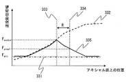
- FIG. 7 shows the difference in the backprojection phase width on the axial plane between the prior art and the present embodiment.
- the horizontal axis is a position on the axial plane, and a position on a line connecting the reference position and the position where the back projection phase width is minimum on the axial plane.
- the vertical axis represents the back projection phase width.
- the image reconstruction method in the prior art is (conventional method 1), as in the method of Patent Document 1, with the backprojection phase width being a constant value and the narrowest value usable in the image (conventional method 2)
- the backprojection phase width being a constant value and the narrowest value usable in the image
- Patent Document 2 there are two ways of setting the back projection phase width to a variable value for each pixel and setting the projection data to the most usable value for each pixel.
- 331 is a graph of the backprojection phase width based on the conventional method 1.
- 332 is a graph of the backprojection phase width based on the conventional method 2.
- Conventional method 1 uses a constant backprojection phase width regardless of position, so noise unevenness is small, but noise is large because backprojection phase width is narrow.
- Conventional method 2 can use a wide backprojection phase width depending on the position, but the backprojection phase width, that is, the amount of noise differs depending on the position, and the magnitude relationship of noise depends on the rotation center axis depending on the slice. As a rotated shape. That is, when the MPR is created, striped noise unevenness occurs.
- a reference position is set on an axial image.
- the reference position 333 is one reference point and is the photographing center position.
- the backprojection phase width at each pixel is calculated according to a function of the distance R from the reference position 333 to the reconstructed pixel position 334.
- 335 is a graph of the backprojection phase width in the present embodiment.
- 335 is calculated according to a function of the distance R from the reference position 333 to the reconstructed pixel position 334.
- the shape of the function that determines 335 is symmetrical at the reference position 333, and decreases monotonously with respect to the distance R from the reference position. That is, in the image reconstruction method according to the present embodiment, the backprojection phase width of each pixel is calculated so as to have the same value concentrically from the reference position 333 in the axial plane according to a predetermined function.
- the amount of data used is the same even if the slice changes if the position on the axial plane is the same.
- striped noise unevenness does not occur when MPR is created.
- the backprojection phase width and the view weight function shape are continuously changed according to the distance from one or more reference points.
- the noise change caused by the corresponding change in the backprojection phase width can be eliminated.
- an image with less noise can be generated by using projection data more efficiently while maintaining a continuous noise change in the axial plane.
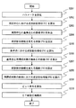
- the central controller 200 of the X-ray CT apparatus 1 accepts parameter settings and performs imaging (S101).
- the central controller 200 displays a parameter setting screen illustrated in FIG. 9 on the display device 211, and accepts parameter settings via the input device 212.
- the parameters set in S101 are: imaging protocol, collimation thickness, beam pitch, scan speed, image slice thickness, tube voltage, tube current, image SD, reconstruction filter, reconstruction FOV, number of slices , Reconstruction center, reference point position, etc.
- imaging conditions such as collimation thickness, beam pitch, image slice thickness, reconstruction filter, reconstruction center, reconstruction FOV, reconstruction conditions
- a recommended value is initially set for the position of the reference point.
- the position of the reconstruction center is initially set to the rotation center on the scanogram.
- the reconstructed FOV is initially set to the FOV corresponding to the part.
- the position of the reference point is initially set at the center of rotation in a normal case.
- the position of the reference point can be changed to any one of the subject center, the reconstruction center, or any one or a plurality of positions as necessary.
- the position of the reference point is set at the subject center.
- even when the subject does not exist at the rotation center position symmetric noise characteristics can be realized at the vertical and horizontal positions from the subject center.
- the noise characteristics are symmetrical in the vertical and horizontal directions from the subject center. realizable.
- the central control device 200 of the X-ray CT apparatus 1 reads the value stored in the storage device 213 based on the parameter value input by the user or the bed moving speed.
- Parameters such as T, number of detector rows Nv, number of extrapolation rows, slope width ⁇ , backprojection phase width lower limit F min , slope width lower limit ⁇ min are also set.
- the lower limit value ⁇ min of the slope width satisfies ⁇ min ⁇ 0, and the lower limit value F min of the backprojection phase width satisfies F min ⁇ 0.5 + ⁇ min .
- the reference position is defined by at least one or a plurality of reference points. As will be described later, the reference position may be further defined by combining one or more reference points and a reference plane.
- examples of the reference point position include a photographing center position, a subject center position, and a reconstruction center position.
- the photographing center position is set as the position of the reference point.
- FIG. 9 shows a graph of relative noise with respect to the position on the axial plane below the scanogram obtained by the positioning scan.
- the horizontal axis represents the position on the axial plane
- the vertical axis represents the relative noise.
- imaging center and “circumference center” are synonymous, and hence the term “circumference center” will be unified.
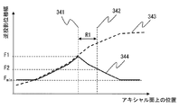
- the arithmetic unit 202 of the X-ray CT apparatus 1 inputs the parameters set in S101, and calculates the back projection phase width (F1) at the orbital center (S102).
- FIG. 10 shows the circling center position 341 and the backprojection phase width F1 with respect to the circling center position.
- the arithmetic unit 202 calculates the distance (R1) between the rotation center position as the reference position and the pixel to be reconstructed (S103).
- FIG. 10 shows the pixel position 342 to be reconstructed and the distance R1 between the rotation center position and the pixel to be reconstructed.
- the arithmetic unit 202 sets a function (f1) that changes the backprojection phase width in accordance with the distance (R1) between the rotation center position that is the reference position and the pixel to be reconstructed (S104).
- FIG. 10 shows a graph 344 showing the function (f1) for changing the backprojection phase width.
- FIG. 10 also shows a graph 343 of the backprojection phase width in which the most projection data can be used in each pixel.
- the computing device 202 substitutes the value of the distance (R1) between the rotation center position that is the reference position and the pixel to be reconstructed into a function (f1) that changes the backprojection phase width, and
- FIG. 10 shows the backprojection phase width F2 with respect to the pixel position to be reconstructed. For reference, FIG. 10 also shows the narrowest backprojection phase width lower limit F min that can be used in an image.
- the arithmetic device 202 F2 so is greater than F min, the slope width gamma views weighting function is larger than the lower limit value gamma min slope width, and back projection phase width in each pixel F2-0.5
- the backprojection phase width F2 and the slope width ⁇ of the view weight function in the pixel to be reconstructed are corrected so as to be smaller.
- the computing device 202 calculates a view weight based on the backprojection phase width F2 and the slope width ⁇ of the view weight function in the corrected reconstruction target pixel (S106).
- the computing device 202 reconstructs a CT image using the view weight calculated in S106 (S107).
- the CT image reconstruction process using view weights uses, for example, the following expression.
- I Image data
- x, y, z Reconstruction target pixel position (mm)
- F pixel (x, y) Back projection phase width of reconstruction target pixel
- W p (•) View weight for parallel beam
- ⁇ parallel beam projection angle (rad)
- P p (•) projection data
- t parallel beam channel position (mm)
- ⁇ detector array position (mm)
- g (•) reconstruction filter is there.
- the computing device 202 calculates the back projection phase width at each pixel so as to have the same value concentrically from the reference position in the axial plane by setting the reference position as the rotation center position. It is possible to realize a noise characteristic that is symmetric with respect to the placed subject in the vertical and horizontal positions.
- the arithmetic unit 202 sets the position of the reference point as the subject center position, and sets the back projection phase width in each pixel with respect to the distance from the reference position in the axial plane. May be calculated so as to be monotonically narrow and have the same value concentrically. As a result, even when the subject is placed out of the center of rotation, a back projection phase width (noise amount) that is symmetric with respect to the subject in the vertical and horizontal positions can be realized.
- the arithmetic unit 202 uses the position of the reference point as the reconstruction center position, and sets the back projection phase width in each pixel to the distance from the reference position in the axial plane.
- it may be calculated so as to be monotonously narrow and have the same value concentrically. As a result, it is possible to reduce noise by using more projection data at the rotation center position while suppressing image quality deterioration due to data extrapolation in the detector row direction at a position away from the rotation center.
- the arithmetic unit 202 may calculate the backprojection phase width at each pixel based on the reduction rate of the backprojection phase width with respect to the reference position at a position away from the reference position by the reference distance. This makes it possible to more easily determine the backprojection phase width at an arbitrary position in the axial image.
- the central controller 200 of the X-ray CT apparatus 1 accepts parameter settings and performs imaging (S201).
- the central controller 200 displays a parameter setting screen illustrated in FIG. 9 on the display device 211, and accepts parameter settings via the input device 212.
- the central control device 200 of the X-ray CT apparatus 1 reads the value stored in the storage device 213 based on the parameter value input by the user or the bed moving speed.
- Parameters such as T, number of detector rows Nv, number of extrapolation rows, slope width ⁇ , backprojection phase width lower limit F min , slope width lower limit ⁇ min are also set.
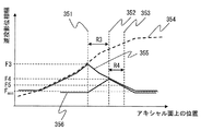
- FIG. 12 shows a lap center position 351 and a position 352 away from the lap center position.
- the reference point is a position 352 away from the rotation center position.
- the arithmetic unit 202 of the X-ray CT apparatus 1 inputs the parameters set in S201, and calculates the back projection phase width (F3) at the orbital center (S202).
- FIG. 12 shows the backprojection phase width F3 with respect to the orbital center position 351.
- the arithmetic unit 202 calculates the distance (R3) between the circling center position and the reference point (S203).
- FIG. 12 shows a graph 355 showing a function (f3) for changing the backprojection phase width.
- a graph 355 shows a locus obtained by turning back the function (f3) for changing the backprojection phase width at the orbital center position 351.
- FIG. 12 also shows a back projection phase width graph 354 in which the most projection data can be used in each pixel.
- the computing device 202 substitutes the value of the distance (R3) between the orbital center position and the reference point into a function (f3) that changes the backprojection phase width, and calculates the backprojection phase width (F4) at the reference point.
- Calculate (S205). That is, the arithmetic unit 202 calculates F4 f3 (R3).
- the arithmetic unit 202 calculates the distance (R4) between the reference point and the pixel to be reconstructed (S206).
- the arithmetic unit 202 sets a function (f4) that changes the backprojection phase width according to the distance (R4) between the reference point and the pixel to be reconstructed (S207).
- FIG. 12 shows a graph 356 showing the function (f4) for changing the backprojection phase width.
- the arithmetic unit 202 substitutes the value of the distance (R4) between the reference point and the pixel to be reconstructed into a function (f4) that changes the backprojection phase width, so that the backprojection phase in the pixel to be reconstructed
- FIG. 12 shows the backprojection phase width F5 at the pixel position 353 to be reconstructed. For reference, FIG. 12 also shows the narrowest backprojection phase width lower limit F min that can be used in an image.
- the arithmetic unit 202 determines that the slope width ⁇ of the view weight function is larger than the lower limit value ⁇ min of the slope width so that F5 is larger than F min and the backprojection phase width F5-0.5 in each pixel.
- the backprojection phase width F5 and the slope width ⁇ of the view weight function in the pixel to be reconfigured are corrected so as to be smaller.
- the computing device 202 calculates a view weight based on the backprojection phase width F5 and the slope width ⁇ of the view weight function in the corrected pixel to be reconstructed (S209).
- the arithmetic unit 202 reconstructs a CT image using the view weight calculated in S209 (S210).
- the CT image reconstruction process using view weights is the same as S107.
- the difference between the second method and the first method is the shape of the function that changes the backprojection phase width.
- the backprojection phase width at the reference point is determined by a function that is symmetric with respect to the orbital center, but in the second method, as shown in FIG. 13, the reference point is less than the maximum backprojection phase width.
- a back projection phase width larger than that of the first method, which is the value of, is used.
- FIG. 13 shows the backprojection phase width F3 with respect to the orbital center position 361. Further, a distance R3 between the rotation center position 361 and the reference point 362 is shown. Further, a graph 365 showing a function (f3) for changing the backprojection phase width is shown. A graph 365 shows a locus obtained by turning back the function (f3) for changing the backprojection phase width at the reference point 362. For reference, a graph 364 of the backprojection phase width in which most projection data can be used in each pixel is also shown. Further, the back projection phase width F4 at the reference point 362 is shown. Further, a distance R4 between the reference point 362 and the pixel position 363 to be reconstructed is shown.
- the central controller 200 of the X-ray CT apparatus 1 accepts parameter settings and performs imaging (S301).
- the central controller 200 displays a parameter setting screen illustrated in FIG. 9 on the display device 211, and accepts parameter settings via the input device 212.
- the central control device 200 of the X-ray CT apparatus 1 reads the value stored in the storage device 213 based on the parameter value input by the user or the bed moving speed.
- Parameters such as T, number of detector rows Nv, number of extrapolation rows, slope width ⁇ , backprojection phase width lower limit F min , slope width lower limit ⁇ min are also set.
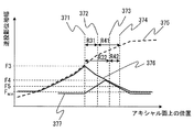
- FIG. 15 shows the rotation center position 371 and positions 372 and 373 away from the rotation center position.
- the two reference points are positions 372 and 373 that are separated from the rotation center position.
- the arithmetic unit 202 of the X-ray CT apparatus 1 inputs the parameters set in S301, and calculates the back projection phase width (F3) at the orbital center (S302).
- FIG. 15 shows the backprojection phase width F3 with respect to the orbital center position 371.
- the arithmetic unit 202 calculates the distance (R31, R32) between the circling center position and the two reference points (S303).
- FIG. 15 shows distances R31 and R32 between the rotation center position 371 and the two reference points 372 and 373.
- FIG. 15 shows a graph 376 showing the function (f3) for changing the backprojection phase width.
- a graph 376 shows a locus obtained by turning back the function (f3) for changing the backprojection phase width at the orbital center position 371.
- FIG. 15 also shows a back projection phase width graph 375 in which the most projection data can be used in each pixel.
- the arithmetic unit 202 substitutes the value of the distance (R31, R32) between the orbital center position and the two reference points into a function (f3) that changes the backprojection phase width, and between the two reference points.
- FIG. 15 shows the backprojection phase width F4 at an arbitrary point located between two reference points.
- the arithmetic unit 202 calculates the distance (R4) between the two reference points and the pixel to be reconstructed (S306).
- FIG. 15 shows distances R41 and R42 between the two reference points 372 and 373 and the pixel position 374 to be reconstructed.
- the arithmetic unit 202 sets a function (f4) for changing the backprojection phase width according to the distance (R41, R42) between the two reference points and the pixel to be reconstructed (S307).
- FIG. 15 shows a graph 377 showing the function (f4) for changing the backprojection phase width.
- a graph 377 shows a locus obtained by folding a function (f3) that changes the backprojection phase width at an arbitrary point located between two reference points.
- the arithmetic unit 202 substitutes the value of the distance (R41, R42) between the two reference points and the pixel to be reconstructed into a function (f4) that changes the backprojection phase width, thereby reconstructing the pixel to be reconstructed.
- FIG. 15 shows the backprojection phase width F5 at the pixel position 374 to be reconstructed. For reference, FIG. 15 also shows the narrowest backprojection phase width lower limit F min that can be used in an image.
- the arithmetic unit 202 determines that the slope width ⁇ of the view weight function is larger than the lower limit value ⁇ min of the slope width so that F5 is larger than F min and the backprojection phase width F5-0.5 in each pixel.
- the backprojection phase width F5 and the slope width ⁇ of the view weight function in the pixel to be reconfigured are corrected so as to be smaller.
- the computing device 202 calculates a view weight based on the backprojection phase width F5 and the slope width ⁇ of the view weight function in the corrected pixel to be reconstructed (S309).
- the arithmetic unit 202 reconstructs a CT image using the view weight calculated in S309 (S310).
- the CT image reconstruction process using view weights is the same as S107.
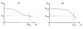
- FIG. 16 (a) shows a graph of the backprojection phase width F r (vertical axis) with respect to the distance R (horizontal axis) between the reference point on the reference plane and the pixel to be reconstructed.
- FIG. 16B shows a graph of the backprojection phase width F z (vertical axis) with respect to the distance Z (horizontal axis) from the reference plane to the pixel to be reconstructed.
- R ref reference distance
- Fz back projection phase width with respect to z-direction distance (Z) from the reference plane to the reconstruction target pixel at the position of the reference distance (R ref )
- Z ref z-direction reference distance
- Fz ref Back projection phase width at z-direction reference distance (Z ref )
- the arithmetic unit 202 may narrow the back projection phase width in each pixel according to the distance in the body axis direction from the reference slice. As a result, the influence of extrapolation in the direction of the detector array in a slice away from the central slice can be reduced without reducing the data efficiency in the central slice.
- Example of distance calculation> The following is an example of a calculation formula for the distance from the reference position on the axial plane to the pixel to be reconstructed.
- the calculation device 202 sets R as the distance between the pixel position to be reconstructed and the reference point.
- the arithmetic unit 202 calculates R based on a composite vector defined from a plurality of reference points.
- z r the position of the reference plane in the detector row direction
- Z the distance from the reference plane to the reconstruction target pixel.
- ⁇ Example of function for changing backprojection phase width The following is an example of a linear function that changes the backprojection phase width.
- f F ( ⁇ ) linear function
- X distance from the reference position to the reconstruction target pixel, or distance from the reference plane to the reconstruction target pixel
- F back projection phase width at the reference position
- X ref reference distance
- F ref Backprojection phase width at the reference distance.
- nonlinear functions that change the backprojection phase width.
- any nonlinear function may be used, and nonlinear functions other than the following may be used.
- the shapes of the following three functions are shown in FIG.
- the backprojection phase width f RZ (R, R ref , Z, Z ref ) Can be calculated, for example, according to the following equation.
- f Z (•): Function for changing the backprojection phase width according to Z (for axial scan), Z: Distance from the reference plane to the target pixel, Z ref : z direction reference distance, Fz ref : z direction reference distance Back projection phase width at (Z ref ), Fr ref : Back projection phase width at the reference position (R ref ) when Z 0, R: Distance from the reference position to the target pixel, R ref : Reference distance, F: Reference The backprojection phase width at the position.
- the reference position is the center position of the lap.
- the reference position is the subject center position.
- the reference position is the reconstruction center position.
- the noise characteristics become symmetric with respect to the rotation center position.
- data can be used most efficiently with respect to the subject placed at the center of rotation.
- the subject is placed at the rotation center position, which is also effective in the sense that the part to be diagnosed is positioned near the rotation center position.
- the circling center position can be easily determined without using projection data.
- the subject center position can be determined by calculating the gravity center position of the subject in the projection data.
- the noise characteristics are symmetric with respect to the reconstruction center position. This is effective when the reconstruction center is a site to be diagnosed.
- the reconstruction center position can be determined by a value input via the input device 212 on the parameter setting screen illustrated in FIG.
- the back projection phase width at each pixel such as the reference position, back projection phase width at the reference point, back projection phase width at the reference distance, lower limit value of the back projection phase width, view weight slope width, lower limit value of the slope width, etc.
- the value of the basic variable for calculation may be fixed regardless of the part, or may be changed according to the part, the imaging protocol, or the reconstruction filter.
- the arithmetic device 202 can change the value of the basic variable according to the part, thereby realizing a desired image quality according to the part.
- the arithmetic device 202 can easily set a desired backprojection phase width corresponding to the part by changing the value of the basic variable according to the reconstruction filter.
- the reference point be the subject center position.
- the reference point in a site where noise is likely to increase, such as the abdomen, it is desirable to set the reference point as the rotation center position so that the noise can be reduced to the maximum.
- the slope width of the view weight and the lower limit value of the slope width it is desirable to set the slope width of the view weight and the lower limit value of the slope width to be wide for parts such as the lower abdomen where the movement is large in order to reduce motion artifacts.
- F Back projection phase width
- ⁇ Detector row direction element size
- N ⁇ Number of detector rows
- N ⁇ ′ Number of extrapolated detector rows
- D X-ray generator 102 (X-ray source) and rotation center The distance from the position
- W the distance between the X-ray generator 102 (X-ray source) and the X-ray detector 103
- T the bed moving speed.
- ⁇ Parameter constraint expression> The following are the upper and lower limits of the backprojection phase width and the upper and lower limits of the slope width of the view weight function. Basically, a set value is used as the slope width of the view weight. However, when the backprojection phase width becomes narrow and the set slope width cannot be secured, a value limited by the lower limit value is used as follows.
- ⁇ view weight slope width
- F backprojection phase width
- ⁇ min view weight slope width lower limit value
- F min backprojection phase width lower limit value
- ⁇ view weight slope width
- F backprojection phase width
- ⁇ max view weight slope width upper limit value
- F max backprojection phase width upper limit value
- the arithmetic device 202 can maintain the number of backprojection views that can be reconfigured even at a position away from the rotation center position by limiting the lower limit value of the slope width and the lower limit value of the backprojection phase width. Further, it is possible to maintain the effect of suppressing artifacts caused by movement and helical artifacts generated at the end of the projection data range to be back-projected in the helical scan.
- FIG. 18 shows a weight function for parallel beam backprojection.
- the weighting functions illustrated in FIG. 18 are: ⁇ : parallel beam projection phase, F: backprojection phase angle width index (backprojection phase width is 2 ⁇ F [rad], F ⁇ 0.5), ⁇ : view weight function slope Width (corrected angle width is 2 ⁇ [rad], 0 ⁇ ⁇ ⁇ F ⁇ 0.5), 2 N-1 ⁇ F (R) ⁇ (R) ⁇ 2 N (N: integer greater than or equal to 0 ) Is defined by the following equation using N satisfying
- Wp View weight function
- G Sub weight gain
- Ws Sub weight
- ⁇ View phase in parallel beam
- ⁇ c1 , ⁇ c2 Center view phase of sub weight
- ⁇ Sub weight reference width
- R From reference position Distance
- ⁇ (R) Slope width index at a position away from the reference position by R (correction angle width is 2 ⁇ (R), 0 ⁇ ⁇ (R) ⁇ F (R) -0.5)
- F (R ) Backprojection phase width index at a position R apart from the reference position (backprojection phase width is 2 ⁇ F (R), F (R) ⁇ 0.5)
- N 2 N ⁇ 1 ⁇ F (R) ⁇ ( R) ⁇ 2 N satisfying ⁇ 2N .
- the weight function Wp shown in the equation (24) changes the weight shape as shown in FIGS. 18 (a) to 18 (c) depending on the values of F and ⁇ according to R.
- 18A shows the case where F ⁇ M
- FIG. 18B shows the case where M ⁇ F ⁇ M + ⁇ / 2
- N is an integer of 0 or more that satisfies 2 N ⁇ 1 ⁇ F ⁇ ⁇ 2 N.
- the weight function for fan beam backprojection is: ⁇ : parallel beam projection phase, F: backprojection phase angle width index (backprojection phase width is 2 ⁇ F [rad], F ⁇ 0.5), ⁇ : view weight function When slope width (correction angle width is 2 ⁇ [rad], 0 ⁇ ⁇ ⁇ F ⁇ 0.5), 2 N-1 ⁇ F (R) ⁇ (R) ⁇ 2 N (N: 0 or more It is defined by the following equation using N satisfying (integer).
- Wp View weight function
- ⁇ Fan beam projection phase
- ⁇ Fan angle
- G Sub weight gain
- Ws Sub weight
- ⁇ Parallel beam (fan beam center beam) projection phase
- ⁇ c1 , ⁇ c2 Offset of two subview weights in phase direction (relative view position from weight center)
- ⁇ Subweight reference width
- R Distance from reference position
- ⁇ (R) Slope at a position away from reference position by R Width index
- F (R) Backprojection phase width index (backprojection at a position R apart from the reference position)
- the phase width is 2 ⁇ F (R), F (R) ⁇ 0.5)
- N 2 N ⁇ 1 ⁇ F (R) ⁇ (R) ⁇ 2 N satisfying an integer of 0 or more.
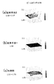
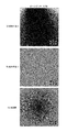
- the comparative example is (conventional method 1), as in the method of patent document 1, and the backprojection phase width is set to a constant value and the narrowest value that can be used in the image (conventional method 2) method of patent document 2
- the back projection phase width is set to a variable value for each pixel, and the projection data is set to the most usable value in each pixel.
- the reference position is set as the rotation center position, and the back projection phase width in each pixel is calculated so as to have the same value concentrically from the reference position in the axial plane.
- the back projection phase width of the conventional method 2 is 1.50 to 2.17
- the back projection phase width of the conventional method 1 is 1.50
- the back projection phase width of the present invention is 1.51 to 1.73. It became.
- the backprojection phase width of the present invention increased by about 15% at the maximum. That is, the present invention uses a backprojection phase width that is about 15% wider than the backprojection phase width of Conventional Method 1.
- the back projection phase width of the conventional method 2 is 0.76 to 1.32
- the back projection phase width of the conventional method 1 is 0.75
- the back projection phase width of the present invention is 0.78 to 1.20. It became.
- the backprojection phase width of the present invention increased by up to 60%. That is, the present invention uses a backprojection phase width that is 60% wider than the backprojection phase width of Conventional Method 1.
- the back projection phase width of the conventional method 2 is 0.62 to 1.17
- the back projection phase width of the conventional method 1 is 0.65
- the back projection phase width of the present invention is 0.67 to 0.93. It became.
- the backprojection phase width of the present invention increased by about 43% at the maximum. That is, the present invention uses a backprojection phase width that is about 43% wider than the backprojection phase width of Conventional Method 1.
- the back projection phase width of the conventional method 2 is 0.56 to 1.00
- the back projection phase width of the conventional method 1 is 0.55
- the back projection phase width of the present invention is 0.56 to 0.75. It became.
- the backprojection phase width of the present invention increased by about 36% at the maximum. That is, the present invention uses a backprojection phase width that is about 36% wider than the backprojection phase width of Conventional Method 1.
- the conventional method 2 has irregular noise unevenness.
- Conventional method 1 has no noise unevenness, but the overall noise has increased.
- Table 1 shows the result of comparison of the amount of noise at the orbital center position.
- the present invention when the beam pitch was 0.58, the present invention was able to reduce the amount of noise by about 2.8% compared to the conventional method 1. In addition, when the beam pitch is 0.83, compared with the conventional method 1, the present invention can reduce the noise amount by about 23.9%. Further, when the beam pitch is 1.08, the present invention can reduce the noise amount by about 13.6% as compared with the conventional method 1. In addition, when the beam pitch is 1.33, compared with the conventional method 1, the present invention can reduce the noise amount by about 10.2%.
- the exposure reduction effect (converted value) of the present invention increased by about 5.4% compared to the conventional method 1.
- the exposure reduction effect (converted value) of the present invention is increased by about 42.1% as compared with the conventional method 1.
- the exposure reduction effect (converted value) of the present invention is increased by about 25.4% compared to the conventional method 1.
- the exposure reduction effect (converted value) of the present invention is increased by about 19.3% compared to the conventional method 1.
- the arithmetic unit 202 calculates the back projection phase width in each pixel according to the function of the distance from the reference position defined by one or a plurality of reference points on the axial plane, A view weight is calculated using the backprojection phase width in each pixel, and the CT image is reconstructed using the view weight. This makes it possible to generate a reconstructed image capable of appropriate image diagnosis that matches the characteristics of a part (particularly, a symmetrical part).
- the object of the present invention has been achieved. While the present invention has been described and illustrated in detail, they are intended for purposes of illustration and illustration only and are not intended to be limiting.
- the scan method is not limited to any of the first generation, second generation, third generation, and fourth generation methods.
- the present invention can be applied to a multi-tube CT, a cathode scan CT, an electron beam CT, and a C-arm CT having a plurality of X-ray sources.
- the present invention is a detector disposed on a cylindrical surface centered on an X-ray source, a flat detector, a detector disposed on a spherical surface centered on an X-ray source, and a rotation axis. It can be applied to any detector such as a detector disposed on a cylindrical surface.
- the gist of the present invention is limited only by the claims.
Landscapes
- Engineering & Computer Science (AREA)
- Physics & Mathematics (AREA)
- General Physics & Mathematics (AREA)
- Theoretical Computer Science (AREA)
- Radiology & Medical Imaging (AREA)
- General Health & Medical Sciences (AREA)
- Medical Informatics (AREA)
- Nuclear Medicine, Radiotherapy & Molecular Imaging (AREA)
- Health & Medical Sciences (AREA)
- Quality & Reliability (AREA)
- Computer Vision & Pattern Recognition (AREA)
- Apparatus For Radiation Diagnosis (AREA)
- Algebra (AREA)
- Mathematical Analysis (AREA)
- Mathematical Optimization (AREA)
- Mathematical Physics (AREA)
- Pure & Applied Mathematics (AREA)
- Image Processing (AREA)
Priority Applications (4)
| Application Number | Priority Date | Filing Date | Title |
|---|---|---|---|
| JP2014512421A JP6181045B2 (ja) | 2012-04-24 | 2013-03-18 | X線ct装置及び画像再構成方法 |
| US14/372,250 US9406121B2 (en) | 2012-04-24 | 2013-03-18 | X-ray CT apparatus and image reconstruction method |
| IN5824DEN2014 IN2014DN05824A (https=) | 2012-04-24 | 2013-03-18 | |
| CN201380005061.0A CN104039232B (zh) | 2012-04-24 | 2013-03-18 | X射线ct装置及图像重构方法 |
Applications Claiming Priority (2)
| Application Number | Priority Date | Filing Date | Title |
|---|---|---|---|
| JP2012098374 | 2012-04-24 | ||
| JP2012-098374 | 2012-04-24 |
Publications (1)
| Publication Number | Publication Date |
|---|---|
| WO2013161443A1 true WO2013161443A1 (ja) | 2013-10-31 |
Family
ID=49482780
Family Applications (1)
| Application Number | Title | Priority Date | Filing Date |
|---|---|---|---|
| PCT/JP2013/057583 Ceased WO2013161443A1 (ja) | 2012-04-24 | 2013-03-18 | X線ct装置及び画像再構成方法 |
Country Status (5)
| Country | Link |
|---|---|
| US (1) | US9406121B2 (https=) |
| JP (1) | JP6181045B2 (https=) |
| CN (1) | CN104039232B (https=) |
| IN (1) | IN2014DN05824A (https=) |
| WO (1) | WO2013161443A1 (https=) |
Cited By (4)
| Publication number | Priority date | Publication date | Assignee | Title |
|---|---|---|---|---|
| WO2016129433A1 (ja) * | 2015-02-12 | 2016-08-18 | 株式会社日立製作所 | X線ct装置、画像処理装置及び画像再構成方法 |
| CN105934066A (zh) * | 2016-07-01 | 2016-09-07 | 中国工程物理研究院流体物理研究所 | 一种粒子束加速器 |
| US20220381705A1 (en) * | 2019-10-11 | 2022-12-01 | Board Of Regents, The University Of Texas System | Variable zoom x-ray computed tomography method for composites |
| JP2025523304A (ja) * | 2023-03-21 | 2025-07-18 | メドフォトン・ゲゼルシャフト・ミット・ベシュレンクテル・ハフツング | 医療システムのための画像再構成方法 |
Families Citing this family (7)
| Publication number | Priority date | Publication date | Assignee | Title |
|---|---|---|---|---|
| JP6571313B2 (ja) * | 2013-05-28 | 2019-09-04 | キヤノンメディカルシステムズ株式会社 | 医用画像診断装置及び制御方法 |
| GB2532077B (en) * | 2014-11-10 | 2017-11-22 | Vision Rt Ltd | Method of calibrating a patient monitoring system for use with a radiotherapy treatment apparatus |
| JP6858259B2 (ja) * | 2016-12-21 | 2021-04-14 | コーニンクレッカ フィリップス エヌ ヴェKoninklijke Philips N.V. | ショートスキャン偏心検出器x線トモグラフィのための冗長重み付け |
| CN109171790B (zh) * | 2018-09-26 | 2022-03-15 | 东软医疗系统股份有限公司 | 一种ct扫描数据的处理方法、装置及ct机 |
| CN111449670B (zh) * | 2020-05-07 | 2022-12-30 | 南京安科医疗科技有限公司 | 一种移动ct系统的步进成像方法 |
| KR102611061B1 (ko) * | 2022-05-02 | 2023-12-07 | 재단법인 아산사회복지재단 | 혈관 영상의 캘리브레이션 방법 및 장치 |
| US12396697B2 (en) | 2022-05-02 | 2025-08-26 | Medipixel, Inc. | Blood vessel image calibration method and device |
Citations (6)
| Publication number | Priority date | Publication date | Assignee | Title |
|---|---|---|---|---|
| JPH119582A (ja) * | 1997-06-23 | 1999-01-19 | Toshiba Corp | X線コンピュータ断層撮影装置 |
| JP2004188163A (ja) * | 2002-10-18 | 2004-07-08 | Hitachi Medical Corp | 断層撮影装置 |
| JP2004337391A (ja) * | 2003-05-16 | 2004-12-02 | Hitachi Medical Corp | X線ct装置 |
| JP2005007169A (ja) * | 2003-06-16 | 2005-01-13 | Toshiba Corp | コーンビーム再構成装置およびコンピュータ断層撮影装置 |
| WO2005077278A1 (ja) * | 2004-02-16 | 2005-08-25 | Hitachi Medical Corporation | 断層撮影像の再構成方法及び断層撮影装置 |
| JP2007185358A (ja) * | 2006-01-13 | 2007-07-26 | Hitachi Medical Corp | X線ct装置 |
Family Cites Families (6)
| Publication number | Priority date | Publication date | Assignee | Title |
|---|---|---|---|---|
| JP2003522576A (ja) * | 2000-02-18 | 2003-07-29 | ウィリアム・ボーモント・ホスピタル | 平坦なパネル画像装置を有するコーンビームコンピュータ断層撮像装置 |
| JP2007044207A (ja) * | 2005-08-09 | 2007-02-22 | Ge Medical Systems Global Technology Co Llc | 放射線ct撮影方法およびx線ct装置 |
| JP2008006032A (ja) * | 2006-06-29 | 2008-01-17 | Ge Medical Systems Global Technology Co Llc | X線ct装置およびx線ct撮影方法 |
| DE102008053108A1 (de) * | 2008-06-27 | 2009-12-31 | Siemens Aktiengesellschaft | Verfahren zur Rekonstruktion von CT-Bilddaten |
| US7933377B2 (en) * | 2009-06-03 | 2011-04-26 | General Electric Company | Method of CT perfusion imaging and apparatus for implementing same |
| CN103501702B (zh) * | 2011-04-28 | 2015-09-02 | 株式会社日立医疗器械 | 医用图像处理装置、医用图像处理方法 |
-
2013
- 2013-03-18 CN CN201380005061.0A patent/CN104039232B/zh active Active
- 2013-03-18 IN IN5824DEN2014 patent/IN2014DN05824A/en unknown
- 2013-03-18 JP JP2014512421A patent/JP6181045B2/ja active Active
- 2013-03-18 US US14/372,250 patent/US9406121B2/en active Active
- 2013-03-18 WO PCT/JP2013/057583 patent/WO2013161443A1/ja not_active Ceased
Patent Citations (6)
| Publication number | Priority date | Publication date | Assignee | Title |
|---|---|---|---|---|
| JPH119582A (ja) * | 1997-06-23 | 1999-01-19 | Toshiba Corp | X線コンピュータ断層撮影装置 |
| JP2004188163A (ja) * | 2002-10-18 | 2004-07-08 | Hitachi Medical Corp | 断層撮影装置 |
| JP2004337391A (ja) * | 2003-05-16 | 2004-12-02 | Hitachi Medical Corp | X線ct装置 |
| JP2005007169A (ja) * | 2003-06-16 | 2005-01-13 | Toshiba Corp | コーンビーム再構成装置およびコンピュータ断層撮影装置 |
| WO2005077278A1 (ja) * | 2004-02-16 | 2005-08-25 | Hitachi Medical Corporation | 断層撮影像の再構成方法及び断層撮影装置 |
| JP2007185358A (ja) * | 2006-01-13 | 2007-07-26 | Hitachi Medical Corp | X線ct装置 |
Cited By (8)
| Publication number | Priority date | Publication date | Assignee | Title |
|---|---|---|---|---|
| WO2016129433A1 (ja) * | 2015-02-12 | 2016-08-18 | 株式会社日立製作所 | X線ct装置、画像処理装置及び画像再構成方法 |
| JPWO2016129433A1 (ja) * | 2015-02-12 | 2017-11-24 | 株式会社日立製作所 | X線ct装置、画像処理装置及び画像再構成方法 |
| US10398392B2 (en) | 2015-02-12 | 2019-09-03 | Hitachi, Ltd. | X-ray CT apparatus, image processing device and image reconstruction method |
| CN105934066A (zh) * | 2016-07-01 | 2016-09-07 | 中国工程物理研究院流体物理研究所 | 一种粒子束加速器 |
| US20220381705A1 (en) * | 2019-10-11 | 2022-12-01 | Board Of Regents, The University Of Texas System | Variable zoom x-ray computed tomography method for composites |
| US12130245B2 (en) * | 2019-10-11 | 2024-10-29 | Board Of Regents, The University Of Texas System | Variable zoom X-ray computed tomography method for composites |
| JP2025523304A (ja) * | 2023-03-21 | 2025-07-18 | メドフォトン・ゲゼルシャフト・ミット・ベシュレンクテル・ハフツング | 医療システムのための画像再構成方法 |
| JP7841179B2 (ja) | 2023-03-21 | 2026-04-06 | メドフォトン・ゲゼルシャフト・ミット・ベシュレンクテル・ハフツング | 医療システムのための画像再構成方法 |
Also Published As
| Publication number | Publication date |
|---|---|
| JPWO2013161443A1 (ja) | 2015-12-24 |
| US9406121B2 (en) | 2016-08-02 |
| US20150093003A1 (en) | 2015-04-02 |
| IN2014DN05824A (https=) | 2015-05-15 |
| CN104039232B (zh) | 2016-09-28 |
| JP6181045B2 (ja) | 2017-08-16 |
| CN104039232A (zh) | 2014-09-10 |
Similar Documents
| Publication | Publication Date | Title |
|---|---|---|
| JP6181045B2 (ja) | X線ct装置及び画像再構成方法 | |
| JP6492005B2 (ja) | X線ct装置、再構成演算装置、及び再構成演算方法 | |
| US9662084B2 (en) | Method and apparatus for iteratively reconstructing tomographic images from electrocardiographic-gated projection data | |
| JP6021311B2 (ja) | X線コンピュータ断層撮影装置 | |
| JP4646810B2 (ja) | 断層撮影像の再構成方法及び断層撮影装置 | |
| JP5537074B2 (ja) | コンピュータ断層撮影装置及び方法 | |
| JP5406063B2 (ja) | 再構成演算装置、再構成演算方法、及びx線ct装置 | |
| WO2012077694A1 (ja) | X線ct装置及び画像再構成方法 | |
| CN106572832A (zh) | 数据处理方法、数据处理装置以及x射线ct装置 | |
| JP5637768B2 (ja) | コンピュータ断層撮影画像の生成方法およびコンピュータ断層撮影装置 | |
| JP2009089810A (ja) | X線ct装置 | |
| JP6665119B2 (ja) | X線ct装置及び画像処理装置 | |
| CN107106114A (zh) | 运算装置、x射线ct装置及图像重构方法 | |
| CN103315758B (zh) | X射线ct装置 | |
| WO2017130657A1 (ja) | X線ct装置、撮影条件設定方法及び撮影条件設定プログラム | |
| US8620052B2 (en) | Projection truncation processing for CBCT | |
| CN107341836B (zh) | 一种ct螺旋扫描图像重建方法及装置 | |
| JP5220580B2 (ja) | X線ct装置 | |
| JP5203750B2 (ja) | 心電同期スキャン方法及びx線コンピュータ断層撮影装置 | |
| JP2020005971A (ja) | X線ct装置及び補正方法 | |
| JP6996881B2 (ja) | X線ct装置 | |
| JP5342682B2 (ja) | X線コンピュータ断層撮影装置 | |
| JP5813022B2 (ja) | X線コンピュータ断層撮影装置 |
Legal Events
| Date | Code | Title | Description |
|---|---|---|---|
| 121 | Ep: the epo has been informed by wipo that ep was designated in this application |
Ref document number: 13782514 Country of ref document: EP Kind code of ref document: A1 |
|
| ENP | Entry into the national phase |
Ref document number: 2014512421 Country of ref document: JP Kind code of ref document: A |
|
| WWE | Wipo information: entry into national phase |
Ref document number: 14372250 Country of ref document: US |
|
| NENP | Non-entry into the national phase |
Ref country code: DE |
|
| 122 | Ep: pct application non-entry in european phase |
Ref document number: 13782514 Country of ref document: EP Kind code of ref document: A1 |