WO2013161204A1 - Dispositif d'entraînement de machine de construction - Google Patents
Dispositif d'entraînement de machine de construction Download PDFInfo
- Publication number
- WO2013161204A1 WO2013161204A1 PCT/JP2013/002465 JP2013002465W WO2013161204A1 WO 2013161204 A1 WO2013161204 A1 WO 2013161204A1 JP 2013002465 W JP2013002465 W JP 2013002465W WO 2013161204 A1 WO2013161204 A1 WO 2013161204A1
- Authority
- WO
- WIPO (PCT)
- Prior art keywords
- oil
- drive device
- brake piston
- brake
- lubricating oil
- Prior art date
Links
Images


Classifications
-
- F—MECHANICAL ENGINEERING; LIGHTING; HEATING; WEAPONS; BLASTING
- F16—ENGINEERING ELEMENTS AND UNITS; GENERAL MEASURES FOR PRODUCING AND MAINTAINING EFFECTIVE FUNCTIONING OF MACHINES OR INSTALLATIONS; THERMAL INSULATION IN GENERAL
- F16H—GEARING
- F16H57/00—General details of gearing
- F16H57/04—Features relating to lubrication or cooling or heating
- F16H57/0409—Features relating to lubrication or cooling or heating characterised by the problem to increase efficiency, e.g. by reducing splash losses
-
- B—PERFORMING OPERATIONS; TRANSPORTING
- B60—VEHICLES IN GENERAL
- B60T—VEHICLE BRAKE CONTROL SYSTEMS OR PARTS THEREOF; BRAKE CONTROL SYSTEMS OR PARTS THEREOF, IN GENERAL; ARRANGEMENT OF BRAKING ELEMENTS ON VEHICLES IN GENERAL; PORTABLE DEVICES FOR PREVENTING UNWANTED MOVEMENT OF VEHICLES; VEHICLE MODIFICATIONS TO FACILITATE COOLING OF BRAKES
- B60T1/00—Arrangements of braking elements, i.e. of those parts where braking effect occurs specially for vehicles
- B60T1/02—Arrangements of braking elements, i.e. of those parts where braking effect occurs specially for vehicles acting by retarding wheels
- B60T1/06—Arrangements of braking elements, i.e. of those parts where braking effect occurs specially for vehicles acting by retarding wheels acting otherwise than on tread, e.g. employing rim, drum, disc, or transmission or on double wheels
- B60T1/062—Arrangements of braking elements, i.e. of those parts where braking effect occurs specially for vehicles acting by retarding wheels acting otherwise than on tread, e.g. employing rim, drum, disc, or transmission or on double wheels acting on transmission parts
-
- E—FIXED CONSTRUCTIONS
- E02—HYDRAULIC ENGINEERING; FOUNDATIONS; SOIL SHIFTING
- E02F—DREDGING; SOIL-SHIFTING
- E02F9/00—Component parts of dredgers or soil-shifting machines, not restricted to one of the kinds covered by groups E02F3/00 - E02F7/00
- E02F9/08—Superstructures; Supports for superstructures
- E02F9/10—Supports for movable superstructures mounted on travelling or walking gears or on other superstructures
- E02F9/12—Slewing or traversing gears
- E02F9/121—Turntables, i.e. structure rotatable about 360°
- E02F9/128—Braking systems
-
- F—MECHANICAL ENGINEERING; LIGHTING; HEATING; WEAPONS; BLASTING
- F16—ENGINEERING ELEMENTS AND UNITS; GENERAL MEASURES FOR PRODUCING AND MAINTAINING EFFECTIVE FUNCTIONING OF MACHINES OR INSTALLATIONS; THERMAL INSULATION IN GENERAL
- F16D—COUPLINGS FOR TRANSMITTING ROTATION; CLUTCHES; BRAKES
- F16D55/00—Brakes with substantially-radial braking surfaces pressed together in axial direction, e.g. disc brakes
- F16D55/24—Brakes with substantially-radial braking surfaces pressed together in axial direction, e.g. disc brakes with a plurality of axially-movable discs, lamellae, or pads, pressed from one side towards an axially-located member
- F16D55/26—Brakes with substantially-radial braking surfaces pressed together in axial direction, e.g. disc brakes with a plurality of axially-movable discs, lamellae, or pads, pressed from one side towards an axially-located member without self-tightening action
- F16D55/36—Brakes with a plurality of rotating discs all lying side by side
- F16D55/40—Brakes with a plurality of rotating discs all lying side by side actuated by a fluid-pressure device arranged in or one the brake
-
- F—MECHANICAL ENGINEERING; LIGHTING; HEATING; WEAPONS; BLASTING
- F16—ENGINEERING ELEMENTS AND UNITS; GENERAL MEASURES FOR PRODUCING AND MAINTAINING EFFECTIVE FUNCTIONING OF MACHINES OR INSTALLATIONS; THERMAL INSULATION IN GENERAL
- F16D—COUPLINGS FOR TRANSMITTING ROTATION; CLUTCHES; BRAKES
- F16D65/00—Parts or details
- F16D65/14—Actuating mechanisms for brakes; Means for initiating operation at a predetermined position
- F16D65/16—Actuating mechanisms for brakes; Means for initiating operation at a predetermined position arranged in or on the brake
- F16D65/18—Actuating mechanisms for brakes; Means for initiating operation at a predetermined position arranged in or on the brake adapted for drawing members together, e.g. for disc brakes
- F16D65/186—Actuating mechanisms for brakes; Means for initiating operation at a predetermined position arranged in or on the brake adapted for drawing members together, e.g. for disc brakes with full-face force-applying member, e.g. annular
-
- F—MECHANICAL ENGINEERING; LIGHTING; HEATING; WEAPONS; BLASTING
- F16—ENGINEERING ELEMENTS AND UNITS; GENERAL MEASURES FOR PRODUCING AND MAINTAINING EFFECTIVE FUNCTIONING OF MACHINES OR INSTALLATIONS; THERMAL INSULATION IN GENERAL
- F16D—COUPLINGS FOR TRANSMITTING ROTATION; CLUTCHES; BRAKES
- F16D2121/00—Type of actuator operation force
- F16D2121/02—Fluid pressure
- F16D2121/04—Fluid pressure acting on a piston-type actuator, e.g. for liquid pressure
-
- F—MECHANICAL ENGINEERING; LIGHTING; HEATING; WEAPONS; BLASTING
- F16—ENGINEERING ELEMENTS AND UNITS; GENERAL MEASURES FOR PRODUCING AND MAINTAINING EFFECTIVE FUNCTIONING OF MACHINES OR INSTALLATIONS; THERMAL INSULATION IN GENERAL
- F16H—GEARING
- F16H57/00—General details of gearing
- F16H57/04—Features relating to lubrication or cooling or heating
- F16H57/045—Lubricant storage reservoirs, e.g. reservoirs in addition to a gear sump for collecting lubricant in the upper part of a gear case
Definitions
- the present invention relates to a drive device for driving a driven part such as an upper swing body in a construction machine such as an excavator.
- the excavator includes a crawler-type lower traveling body, an upper revolving body mounted on the lower traveling body so as to be rotatable about an axis perpendicular to the ground, and a work attachment attached to the upper revolving body.
- the excavator turning drive device turns the upper turning body.
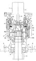
- the swivel drive device has a hydraulic motor or electric motor as a drive source and a gear mechanism that decelerates the rotational force of the motor, and transmits the rotational force decelerated by the gear mechanism to the upper revolving body as a driven part.
- a reduction gear A reduction gear.
- the motor and the speed reducer are provided side by side in the axial direction of the swivel drive device in a state where the rotation axes of the motor and the speed reducer coincide.
- the motor and the speed reducer are attached to the upper frame in a vertical posture in which the motor is disposed on the upper side with respect to the speed reducer.
- the reduction gear is composed of a single-stage or multiple-stage planetary gear type reduction section equipped with a sun gear, a planetary gear and a ring gear.
- the output of the reduction gear is transmitted to the upper swing body, whereby the upper swing body rotates.
- lubricating oil is injected into the reducer casing.
- each stage reduction part (planetary gear mechanism) is lubricated.
- the portion of the lubricating oil in the casing located near the outer periphery is pushed up along the inner wall surface of the casing due to the centrifugal force and pumping action generated by the operation of the speed reducer.
- the oil level of the lubricating oil in the casing becomes a mortar shape, or the lubricating oil in the casing is scattered upward. This phenomenon becomes more severe as the temperature of the lubricating oil rises and the oil level rises accordingly.
- the lubricating oil returning to the speed reduction portion increases resistance to stirring the lubricating oil when the speed reduction portion is activated. As a result, there arises a problem that an energy loss generated when the speed reduction unit operates is increased.
- Patent Documents 1 and 2 are known.
- a tank is provided outside the casing, and an upper passage and a lower passage with a throttle are provided so as to straddle the inside and outside of the casing.
- the tank, the upper passage, and the lower passage are provided outside the casing, so that the structure of the swivel drive device as a whole becomes complicated and large.
- the manufacturing cost of the turning drive device is greatly increased, and the peripheral layout of the turning drive device may be adversely affected.
- the tank cannot be enlarged from the viewpoint of suppressing the enlargement of the swing drive device, and as a result, the capacity of the tank cannot be increased. Also from this point, the amount of lubricating oil that can be stored in the tank is reduced, and as a result, the effect of reducing the energy loss is further reduced.
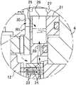
- the brake mechanism includes a ring-shaped brake piston and a brake plate that generates the braking force by the pressing force of the brake piston, and the brake piston
- a plurality of oil reservoirs that are spaces provided in a plurality of locations in the circumferential direction of the piston and capable of storing lubricating oil; an oil inlet that introduces the lubricating oil that rises during operation of the drive device; And an oil outlet for discharging the lubricating oil stored in each oil reservoir.
- FIG. 5 is a view corresponding to FIG. 4 illustrating a brake piston of a turning drive device according to a second embodiment of the present invention.
- the motor and the speed reducer are provided side by side in the vertical direction with the centers of their rotation axes being coincident, and the lubricating oil is injected into the casing of the speed reducer.
- the present invention can also be applied to other drive devices having the configuration described above. Further, the present invention can be similarly applied to a drive device for a construction machine other than an excavator and having the above-described configuration.
- the turning drive device drives an upper turning body as a driven portion in an excavator.
- a motor 1 as a drive source and a rotational force of the motor 1 are used.
- a speed reducer 2 that transmits the reduced rotational force to the upper swing body.
- the lubricant oil O is agitated by the operation of the respective stage speed reducers 9 to 11, and the sun gears S1 to S3 and the spiders 12 to 14 of the respective stage speed reducers 9 to 11 are rotated.
- a centrifugal force is applied to the lubricating oil O by the revolutions of the planetary gears P1 to P3 of the respective stage speed reduction units 9 to 11. Due to the centrifugal force applied to the lubricating oil O, the portion of the lubricating oil O near the outer periphery rises along the inner wall surface of the casing 4, and as a result, as indicated by a two-dot chain line in FIGS. The whole oil surface becomes a mortar shape. Further, during the operation of the turning drive device, the lubricating oil O is scattered upward in each direction by the pumping action of the speed reduction units 9 to 11.
- the brake mechanism 19 includes a thick ring-shaped brake piston 21, a plurality of springs 20 that apply a downward pressing force to the brake piston 21, a pressure chamber 22 into which hydraulic pressure is introduced when the motor 1 rotates, a brake piston A plurality of rotating shaft side brake plates 23 and a plurality of casing side brake plates 24 are provided below 21.
- the casing side brake plate 24 is splined to the inner periphery of the casing 4.
- the casing-side brake plate 24 is attached to the casing 4 in a state in which the casing-side brake plate 24 cannot rotate relative to the casing 4 and is relatively movable up and down.
- each concave groove 31 may be formed in a straight line with a constant width, or may be formed so as to widen toward the outer peripheral portion side of the rotating shaft side brake plate 23 as illustrated.
Abstract
Priority Applications (5)
| Application Number | Priority Date | Filing Date | Title |
|---|---|---|---|
| CN201380021784.XA CN104246310B (zh) | 2012-04-26 | 2013-04-11 | 工程机械的驱动装置 |
| US14/397,071 US9476498B2 (en) | 2012-04-26 | 2013-04-11 | Drive device for construction machine |
| EP13781954.6A EP2843264B1 (fr) | 2012-04-26 | 2013-04-11 | Dispositif d'entraînement de machine de construction |
| KR1020167000673A KR101625356B1 (ko) | 2012-04-26 | 2013-04-11 | 건설 기계의 구동 장치 |
| KR1020147032166A KR101611120B1 (ko) | 2012-04-26 | 2013-04-11 | 건설 기계의 구동 장치 |
Applications Claiming Priority (2)
| Application Number | Priority Date | Filing Date | Title |
|---|---|---|---|
| JP2012-101063 | 2012-04-26 | ||
| JP2012101063A JP5969806B2 (ja) | 2012-04-26 | 2012-04-26 | 建設機械の駆動装置 |
Publications (1)
| Publication Number | Publication Date |
|---|---|
| WO2013161204A1 true WO2013161204A1 (fr) | 2013-10-31 |
Family
ID=49482556
Family Applications (1)
| Application Number | Title | Priority Date | Filing Date |
|---|---|---|---|
| PCT/JP2013/002465 WO2013161204A1 (fr) | 2012-04-26 | 2013-04-11 | Dispositif d'entraînement de machine de construction |
Country Status (6)
| Country | Link |
|---|---|
| US (1) | US9476498B2 (fr) |
| EP (1) | EP2843264B1 (fr) |
| JP (1) | JP5969806B2 (fr) |
| KR (2) | KR101625356B1 (fr) |
| CN (1) | CN104246310B (fr) |
| WO (1) | WO2013161204A1 (fr) |
Cited By (2)
| Publication number | Priority date | Publication date | Assignee | Title |
|---|---|---|---|---|
| US20140296015A1 (en) * | 2013-03-29 | 2014-10-02 | Sumitomo Heavy Industries, Ltd. | Shovel |
| JP2015197144A (ja) * | 2014-03-31 | 2015-11-09 | 住友重機械工業株式会社 | 旋回駆動装置 |
Families Citing this family (8)
| Publication number | Priority date | Publication date | Assignee | Title |
|---|---|---|---|---|
| CN104769315B (zh) * | 2012-11-05 | 2018-04-24 | 住友重机械工业株式会社 | 挖土机 |
| DE102015013611A1 (de) * | 2015-10-21 | 2017-04-27 | Liebherr-Aerospace Lindenberg Gmbh | Stellantrieb für ein Hochauftriebssystem eines Luftfahrzeuges |
| JP2018076967A (ja) * | 2018-01-23 | 2018-05-17 | 住友重機械工業株式会社 | ショベル |
| JP2019154101A (ja) * | 2018-02-28 | 2019-09-12 | 株式会社小松製作所 | 電動機、回転駆動システム及び油圧ショベル |
| CN110454550B (zh) * | 2018-05-08 | 2022-02-01 | 德纳(无锡)技术有限公司 | 用于车辆的多级行星减速传动装置和安装结构 |
| WO2020103136A1 (fr) * | 2018-11-23 | 2020-05-28 | Guangxi Liugong Machinery Co., Ltd. | Module d'engrenage planétaire pour entraînement oscillant |
| CN111692244B (zh) * | 2020-06-28 | 2022-01-04 | 东北林业大学 | 一种重载电动车辆轮边动力及制动系统总成 |
| JP7201012B2 (ja) * | 2021-01-06 | 2023-01-10 | コベルコ建機株式会社 | 建設機械の旋回ユニット |
Citations (6)
| Publication number | Priority date | Publication date | Assignee | Title |
|---|---|---|---|---|
| JPH0441554U (fr) * | 1990-07-31 | 1992-04-08 | ||
| JP2006025580A (ja) * | 2004-06-07 | 2006-01-26 | Kobelco Contstruction Machinery Ltd | ブレーキ付き縦型電動駆動装置及び作業機械 |
| JP2008232270A (ja) | 2007-03-20 | 2008-10-02 | Komatsu Ltd | 電動旋回装置 |
| JP2008232269A (ja) | 2007-03-20 | 2008-10-02 | Komatsu Ltd | 電動旋回装置 |
| JP2011214586A (ja) * | 2010-03-31 | 2011-10-27 | Komatsu Ltd | 減速機及び旋回装置 |
| JP2012077862A (ja) * | 2010-10-04 | 2012-04-19 | Hitachi Constr Mach Co Ltd | 湿式ブレーキ装置 |
Family Cites Families (12)
| Publication number | Priority date | Publication date | Assignee | Title |
|---|---|---|---|---|
| US1967664A (en) * | 1933-11-16 | 1934-07-24 | Wagner Electric Corp | Liquid pressure mechanism |
| US2069914A (en) * | 1936-05-29 | 1937-02-09 | New York Air Brake Co | Air brake |
| JPS5913144A (ja) * | 1982-07-14 | 1984-01-23 | Akebono Brake Ind Co Ltd | 湿式デイスクブレ−キの自然冷却方法 |
| JPH0648028B2 (ja) * | 1985-02-08 | 1994-06-22 | ヤンマーディーゼル株式会社 | 湿式多板ブレ−キ装置 |
| JPH0441554A (ja) | 1990-06-07 | 1992-02-12 | Titan Kogyo Kk | 熱可塑性樹脂組成物 |
| JPH05296269A (ja) | 1992-04-14 | 1993-11-09 | Sumitomo Electric Ind Ltd | フルディスクタイプブレーキ摩擦板 |
| US6029786A (en) * | 1998-02-20 | 2000-02-29 | Midwest Brake Bond Company | Lubrication system for an oil shear clutch/brake drive |
| CN1965458A (zh) * | 2004-06-07 | 2007-05-16 | 神钢建设机械株式会社 | 具有制动器的竖直电驱动装置和工作机 |
| JP4860562B2 (ja) | 2007-06-30 | 2012-01-25 | 東芝機械株式会社 | 建設機械における旋回駆動機構の潤滑方法および装置 |
| JP4924523B2 (ja) | 2008-04-18 | 2012-04-25 | トヨタ自動車株式会社 | ベルト式無段変速機 |
| EP2540916B1 (fr) | 2010-02-22 | 2019-08-28 | Hitachi Construction Machinery Co., Ltd. | Dispositif de pivotement pour engin de construction |
| JP5533494B2 (ja) | 2010-09-24 | 2014-06-25 | アイシン精機株式会社 | 車両用クラッチ装置 |
-
2012
- 2012-04-26 JP JP2012101063A patent/JP5969806B2/ja active Active
-
2013
- 2013-04-11 KR KR1020167000673A patent/KR101625356B1/ko active IP Right Grant
- 2013-04-11 US US14/397,071 patent/US9476498B2/en active Active
- 2013-04-11 CN CN201380021784.XA patent/CN104246310B/zh active Active
- 2013-04-11 EP EP13781954.6A patent/EP2843264B1/fr active Active
- 2013-04-11 WO PCT/JP2013/002465 patent/WO2013161204A1/fr active Application Filing
- 2013-04-11 KR KR1020147032166A patent/KR101611120B1/ko active IP Right Grant
Patent Citations (6)
| Publication number | Priority date | Publication date | Assignee | Title |
|---|---|---|---|---|
| JPH0441554U (fr) * | 1990-07-31 | 1992-04-08 | ||
| JP2006025580A (ja) * | 2004-06-07 | 2006-01-26 | Kobelco Contstruction Machinery Ltd | ブレーキ付き縦型電動駆動装置及び作業機械 |
| JP2008232270A (ja) | 2007-03-20 | 2008-10-02 | Komatsu Ltd | 電動旋回装置 |
| JP2008232269A (ja) | 2007-03-20 | 2008-10-02 | Komatsu Ltd | 電動旋回装置 |
| JP2011214586A (ja) * | 2010-03-31 | 2011-10-27 | Komatsu Ltd | 減速機及び旋回装置 |
| JP2012077862A (ja) * | 2010-10-04 | 2012-04-19 | Hitachi Constr Mach Co Ltd | 湿式ブレーキ装置 |
Non-Patent Citations (1)
| Title |
|---|
| See also references of EP2843264A4 |
Cited By (3)
| Publication number | Priority date | Publication date | Assignee | Title |
|---|---|---|---|---|
| US20140296015A1 (en) * | 2013-03-29 | 2014-10-02 | Sumitomo Heavy Industries, Ltd. | Shovel |
| US9062743B2 (en) * | 2013-03-29 | 2015-06-23 | Sumitomo Heavy Industries, Ltd. | Shovel |
| JP2015197144A (ja) * | 2014-03-31 | 2015-11-09 | 住友重機械工業株式会社 | 旋回駆動装置 |
Also Published As
| Publication number | Publication date |
|---|---|
| KR101625356B1 (ko) | 2016-05-27 |
| EP2843264B1 (fr) | 2016-09-21 |
| US20150126319A1 (en) | 2015-05-07 |
| JP5969806B2 (ja) | 2016-08-17 |
| EP2843264A1 (fr) | 2015-03-04 |
| KR20160011699A (ko) | 2016-02-01 |
| CN104246310A (zh) | 2014-12-24 |
| CN104246310B (zh) | 2017-04-19 |
| JP2013228055A (ja) | 2013-11-07 |
| KR101611120B1 (ko) | 2016-04-08 |
| KR20140146206A (ko) | 2014-12-24 |
| US9476498B2 (en) | 2016-10-25 |
| EP2843264A4 (fr) | 2015-08-12 |
Similar Documents
| Publication | Publication Date | Title |
|---|---|---|
| WO2013161204A1 (fr) | Dispositif d'entraînement de machine de construction | |
| KR101751865B1 (ko) | 건설기계의 선회 장치 | |
| JP5315279B2 (ja) | 減速機及び旋回装置 | |
| JP4782716B2 (ja) | 電動旋回装置 | |
| EP2360047A1 (fr) | Unité de commande de véhicule pour camion-benne | |
| JP2012122552A (ja) | 建設機械の駆動装置 | |
| JP5816071B2 (ja) | 建設機械の駆動装置 | |
| JP5605196B2 (ja) | 建設機械の駆動装置 | |
| JP2011105211A (ja) | 作業用車両の終減速装置 | |
| JP6686855B2 (ja) | 車両用動力伝達装置 | |
| JP6408425B2 (ja) | 動力伝達装置およびモータグレーダ | |
| JP5112919B2 (ja) | 減速機付き縦型モータ装置 | |
| JP2013124480A (ja) | 建設機械 | |
| JP6512131B2 (ja) | 車両用の遠心圧縮機 | |
| CN111033081A (zh) | 减速装置 | |
| JP7201012B2 (ja) | 建設機械の旋回ユニット | |
| US11560935B2 (en) | Speed reducer and construction machine | |
| JP4964177B2 (ja) | 減速機付き縦型モータ装置 | |
| JP2011185402A (ja) | 車両用差動歯車装置 | |
| JP2016150611A (ja) | インホイールモータ駆動装置 | |
| JP2014114953A (ja) | 単純遊星減速装置 |
Legal Events
| Date | Code | Title | Description |
|---|---|---|---|
| 121 | Ep: the epo has been informed by wipo that ep was designated in this application |
Ref document number: 13781954 Country of ref document: EP Kind code of ref document: A1 |
|
| WWE | Wipo information: entry into national phase |
Ref document number: 14397071 Country of ref document: US |
|
| NENP | Non-entry into the national phase |
Ref country code: DE |
|
| REEP | Request for entry into the european phase |
Ref document number: 2013781954 Country of ref document: EP |
|
| WWE | Wipo information: entry into national phase |
Ref document number: 2013781954 Country of ref document: EP |
|
| ENP | Entry into the national phase |
Ref document number: 20147032166 Country of ref document: KR Kind code of ref document: A |