WO2013145349A1 - 画像生成装置、表示装置、テレビジョン受像機、電子黒板、デジタルサイネージ、携帯型情報端末、表示システム、画像生成方法、方法、プログラム、及び、記録媒体 - Google Patents
画像生成装置、表示装置、テレビジョン受像機、電子黒板、デジタルサイネージ、携帯型情報端末、表示システム、画像生成方法、方法、プログラム、及び、記録媒体 Download PDFInfo
- Publication number
- WO2013145349A1 WO2013145349A1 PCT/JP2012/068017 JP2012068017W WO2013145349A1 WO 2013145349 A1 WO2013145349 A1 WO 2013145349A1 JP 2012068017 W JP2012068017 W JP 2012068017W WO 2013145349 A1 WO2013145349 A1 WO 2013145349A1
- Authority
- WO
- WIPO (PCT)
- Prior art keywords
- display device
- image
- camera
- display
- image generation
- Prior art date
- Legal status (The legal status is an assumption and is not a legal conclusion. Google has not performed a legal analysis and makes no representation as to the accuracy of the status listed.)
- Ceased
Links
Images








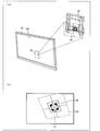

Classifications
-
- H—ELECTRICITY
- H04—ELECTRIC COMMUNICATION TECHNIQUE
- H04N—PICTORIAL COMMUNICATION, e.g. TELEVISION
- H04N5/00—Details of television systems
- H04N5/64—Constructional details of receivers, e.g. cabinets or dust covers
-
- H—ELECTRICITY
- H04—ELECTRIC COMMUNICATION TECHNIQUE
- H04N—PICTORIAL COMMUNICATION, e.g. TELEVISION
- H04N21/00—Selective content distribution, e.g. interactive television or video on demand [VOD]
- H04N21/40—Client devices specifically adapted for the reception of or interaction with content, e.g. set-top-box [STB]; Operations thereof
- H04N21/43—Processing of content or additional data, e.g. demultiplexing additional data from a digital video stream; Elementary client operations, e.g. monitoring of home network or synchronising decoder's clock; Client middleware
- H04N21/431—Generation of visual interfaces for content selection or interaction; Content or additional data rendering
- H04N21/4312—Generation of visual interfaces for content selection or interaction; Content or additional data rendering involving specific graphical features, e.g. screen layout, special fonts or colors, blinking icons, highlights or animations
Definitions
- the present invention relates to an image generation device, a display device including the image generation device, a portable information terminal, and a display system.
- the present invention relates to a television receiver including a display device, an electronic blackboard, and digital signage.
- the present invention relates to an image generation method of the image generation apparatus, a method for performing alignment, a program for operating the image generation apparatus, and a recording medium on which the program is recorded.
- television receivers (hereinafter simply referred to as televisions) equipped with a cooperation function with mobile terminals typified by smartphones and mobile phones have become widespread.
- a portable terminal can operate a television by wireless communication using Wi-Fi (registered trademark) or the like, and can display an image displayed on the television on the portable terminal.
- Wi-Fi registered trademark
- Patent Document 1 As a technique for aligning positions, for example, in Patent Document 1, an image including an alignment mark made up of a captured cross-shaped portion and a rectangular portion is enlarged and displayed on a monitor, and the displayed alignment mark is stored in advance. A technique for improving the setting accuracy of a detection position by performing alignment with a reference pattern is disclosed.
- Patent Document 2 discloses that an operator can temporarily place a protrusion on a jig at a position adjacent to a connection portion between the protrusion and a jig attached to the main body of the display device. A technique for reducing the burden on the user is disclosed.
- Japanese Patent Publication Japanese Patent Laid-Open No. 10-040389 (published on February 13, 1998)” Japanese Patent Publication “Japanese Unexamined Patent Application Publication No. 2008-069937 (published March 27, 2008)”
- the technique described in Patent Document 1 is a technique related to alignment in a plane, and does not describe anything about alignment in a three-dimensional space. For this reason, even if the work described in Patent Document 1 is used and the work is performed while looking at the monitor, it is difficult to recognize the distance between the TV and the wall, and the TV is unintentionally hit against the wall. Sometimes the TV is dropped.
- Patent Document 2 is a technique for temporarily reducing the burden on the operator during the operation of attaching the display device to the jig, and also easily aligns the display device and the jig. There was a problem that I could not.
- the present invention has been made to solve the above-described problems, and a main object of the present invention is to provide a display device that can easily perform alignment in a three-dimensional space.
- an image generation device performs alignment between a first object to which a camera is attached and a second object to which a planar marker is attached.
- the image generating apparatus includes a synthesizing unit that generates the reference image by synthesizing the reference object with the original image captured by the camera, and the reference object includes the reference image. Is a reference object based on the plane marker.
- an image generation method of an image generation apparatus provides a position between a first object to which a camera is attached and a second object to which a planar marker is attached.
- An image generation method of an image generation apparatus for generating a reference image to be referred to for alignment comprising: a combining step of generating the reference image by combining a reference object with an original image captured by the camera.
- the reference object is a reference object based on the planar marker in the three-dimensional space represented by the reference image.
- the image generation apparatus can easily position the positional relationship between the first object and the second object by combining the reference object with the original image by the combining unit.
- the reference image that can be understood can be generated. Accordingly, the user can easily grasp the positional relationship between the first object and the second object in the three-dimensional space by referring to the reference image.
- a display device is a display device including the image generation device and a display panel, and the display device is the first object, and the display A reference image generated by the image generation device from an original image captured by the camera disposed on the back surface of the display device, with a hook provided on the wall surface for hooking the device as a second object. Is displayed on the display panel.
- the display device can present the positional relationship between the display device and the hooking tool to the user by displaying the reference image on the display panel.
- the user can easily perform alignment in the three-dimensional space between the display device and the hook by referring to the reference image displayed on the display panel.
- the user since the user does not need to look into the back surface of the display device in order to align the position of the display device and the latch, the user can more securely latch the display device on the latch. be able to.
- a television receiver comprising the display device, an electronic blackboard comprising the display device, and a digital signage comprising the display device are also included in the scope of the present invention.
- a portable information terminal is a portable information terminal including the above-described image generation device and the camera, and the portable information terminal
- the image generation is performed from the original image captured by the camera, with the display device attached to the first object as the first object, and the latch installed on the wall surface for hanging the display device as the second object.
- a reference image generated by the device is transmitted to the display device.
- the said portable information terminal can transmit the said reference image to the said display apparatus, in the said display apparatus, the positional relationship of the said display apparatus and the said latch is shown to the user. Can be presented.
- the user can easily perform alignment in the three-dimensional space between the display device and the hook by referring to the reference image displayed on the display device.
- the user since the user does not need to look into the back surface of the display device in order to align the position of the display device and the latch, the user can more securely latch the display device on the latch. be able to.
- a display system includes a portable information terminal including the above-described image generation device and the camera, and a display panel that displays the reference image.
- the portable information terminal includes the display device as the first object, and a second locking device installed on the wall surface for hooking the display device.
- a reference image generated by the image generation device is transmitted from the original image captured by the camera to the display device, and the display device includes a storage unit for storing the portable information terminal.
- the reference image transmitted from the portable information terminal stored in the storage unit is displayed on the display panel.
- the said display system displays the said reference image transmitted from the said portable information terminal stored in the storage part with which the said display apparatus is equipped on the said display panel with which the said display apparatus is equipped.
- the positional relationship between the display device and the hook can be presented to the user.
- the user can easily perform alignment in the three-dimensional space between the display device and the hook by referring to the reference image displayed on the display panel.
- the user since the user does not need to look into the back surface of the display device in order to align the position of the display device and the latch, the user can more securely latch the display device on the latch. be able to.
- a method for performing alignment performs alignment between a first object to which a camera is attached and a second object to which a planar marker is attached.
- An adjustment step is included, and the reference object is a reference object based on the planar marker in the three-dimensional space represented by the reference image.
- the first object and the second object are referred to with reference to the reference image generated by combining the reference object based on the planar marker with the original image. Adjust the relative position to the object. As a result, the user can easily grasp the relative positional relationship between the first object and the second object in the three-dimensional space, and the relative position between the first object and the second object. Can be adjusted.
- the user can easily adjust the relative position of the first object and the second object in the three-dimensional space by referring to the reference image.
- the relative position can be adjusted more safely.
- a program for operating the image generation apparatus which is a program that causes a computer to function as each of the above-described units, and a computer-readable program that records these programs Recording media are also included in the scope of the present invention.
- an image generation device performs alignment between a first object to which a camera is attached and a second object to which a planar marker is attached.
- the image generating apparatus includes a synthesizing unit that generates the reference image by combining the reference object with the original image captured by the camera, and the reference object includes the reference image. Is a reference object based on the plane marker.
- an image generation method of an image generation apparatus provides a position between a first object to which a camera is attached and a second object to which a planar marker is attached.
- An image generation method of an image generation apparatus for generating a reference image to be referred to for alignment comprising: a combining step of generating the reference image by combining a reference object with an original image captured by the camera.
- the reference object is a reference object based on the planar marker in the three-dimensional space represented by the reference image.
- a method for performing alignment includes a position between a first object to which a camera is attached and a second object to which a planar marker is attached.
- a method for performing matching wherein a relative position between the first object and the second object is determined with reference to a reference image generated by combining a reference object with an original image captured by the camera.
- An adjustment step of adjusting is included, wherein the reference object is a reference object based on the planar marker in the three-dimensional space represented by the reference image.
- the user can easily align the first object and the second object in a three-dimensional space by referring to the reference image.
- FIG. 1 It is a block diagram which shows the outline of a structure of the display system which concerns on one Embodiment of this invention. It is a general-view figure which shows the relationship between the display system which concerns on one Embodiment of this invention, and a wall hanging metal fitting. It is a general-view figure which shows the back surface of the display apparatus which concerns on one Embodiment of this invention. It is a figure which shows the process of the production
- FIG. 10C shows the process of calculating the attitude of the mobile terminal based on the positional relationship between the planar marker and the mobile terminal
- FIG. 3D shows a three-dimensional object, a cross frame, and a plane marker displayed on a display unit included in the display device.
- It is a flowchart which shows the flow of the attachment process of a display system at the time of the attachment operation
- the figure (a) shows an example of the attitude
- FIG. 5 is an overview diagram illustrating another example of the posture relationship between the display device and the wall hanging bracket according to the embodiment of the present invention, and FIG. 5A illustrates another example of the posture of the display device with respect to the wall hanging bracket;
- FIG. (B) shows another example of a screen showing the posture relationship between the display device and the wall-hanging bracket displayed on the display unit. It is a figure which shows an example of the screen showing the distance relationship between a display apparatus and a wall hanging bracket in one Embodiment of this invention, and the distance relationship between a display apparatus and a wall hanging bracket displayed on a display part.
- FIG. 10B shows a state where the distance between the display device and the wall-hanging bracket is long
- FIG. 10B shows a state where the distance between the display device and the wall-hanging bracket is short
- FIG. A state where the apparatus and the wall mounting bracket are overlapped (attached) is shown.
- FIG. 5B shows a state in which an audio signal indicating that the attachment has been completed is output from the display device.
- the state displayed in is shown.
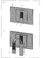
- BRIEF DESCRIPTION OF THE DRAWINGS It is a general-view figure which shows the back surface of the display apparatus which concerns on one Embodiment of this invention,
- the same figure (a) is a general-view figure which shows the back surface of a display apparatus
- the same figure (b) is a storage part from a display apparatus.
- the figure (a) is an outline showing the back of a display
- the figure (b) is a storage part.
- FIG. 10C Shows a state where the direction of the camera is changed
- FIG. 10C shows a state where the camera faces the front of the display device.
- FIG. 1 It is a figure which shows the process of the production
- the figure (a) shows the plane marker seen from the front, (B) shows imaging of a planar marker by a portable terminal, (c) in the figure shows the process of calculating the attitude of the portable terminal based on the positional relationship between the planar marker and the portable terminal, and (d) in FIG.
- the plane object displayed on the display part with which a display apparatus is provided, a cross frame, and a plane marker are shown.
- FIG. 5B shows another example of a screen that is displayed on the display unit and represents the posture relationship between the display device and the wall-hanging bracket.
- the image generation apparatus is provided in a portable terminal (portable information terminal) that constitutes a display system together with the display apparatus
- a portable terminal portable information terminal
- the present invention is not limited to this.
- the configuration provided in the display device may be adopted.
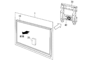
- FIG. 2 is an overview diagram showing the relationship between the display system 1 and the wall-hanging metal fitting 30 according to the present embodiment.
- FIG. 3 is a schematic view showing the back surface of the display device 10 according to the present embodiment.
- the display system 1 includes a display device (first object) 10 and a mobile terminal 20. Further, the display device 10 included in the display system 1 can be attached to, for example, a wall hanging metal fitting (second object, hook) 30 installed on a wall or the like. Further, as shown in FIG. 2, a planar marker 40 is attached to the wall hanging bracket 30.
- the portable terminal 20 is stored in the storage unit 12 provided on the back surface of the display device 10.
- an attachment portion 11 for attaching the display device 10 to the wall mount 30 is provided on the back surface of the display device 10. Note that the storage of the portable terminal 20 in the storage unit 12 and the removal from the storage unit 12 will be described later.
- the display device 10 according to the present embodiment can be realized by, for example, a television receiver.
- the present invention is not limited to this, and may be realized by an electronic blackboard, digital signage, or the like.
- the portable terminal which concerns on this embodiment is realizable with a smart phone, for example, this invention is not limited to this, You may implement
- FIG. 1 is a block diagram showing an outline of the configuration of a display system 1 according to the present embodiment.
- the mobile terminal 20 constituting the display system 1 includes a camera 201, a control unit (compositing means, image generation device) 202, an image processing unit 203, a display unit 204, and a wireless communication unit 205. ing.
- the control unit 202 controls each unit included in the mobile terminal 20.
- the control unit 202 performs control according to an image (original image) captured by the camera 201.
- the image captured by the camera 201 may be a still image or a moving image.
- a case where an image is a moving image will be described as an example.
- the control unit 202 acquires image data representing an image captured by the camera 201 from the camera 201.
- the control unit 202 when the control unit 202 acquires image data from the camera 201, the control unit 202 has a detection function of detecting the planar marker 40 from an image represented by the acquired image data.
- the detection function included in the control unit 202 is, for example, how far the same pattern as the pattern specified in advance as the pattern of the predetermined planar marker 40 is away from the camera in which direction in the three-dimensional space represented by the image.
- the detection may be realized by a known technique, but the present invention is not limited to this.
- the pattern of the plane marker 40 may be specified by an operation unit for operating the mobile terminal 20 or a touch panel (both not shown), or by a pattern stored in advance in a storage unit (not shown). May be.
- the control unit 202 When the planar marker 40 provided on the wall bracket 30 is imaged by the camera 201, the control unit 202 generates a three-dimensional object (hereinafter also referred to as a three-dimensional object) (reference object), and the generated three-dimensional object A reference image synthesized so as to stand on the plane marker 40 in the three-dimensional space represented by the captured image is generated.
- the control unit 202 functions as an image generation apparatus including a synthesis unit.
- control unit 202 calculates the distance between the mobile terminal 20 and the flat marker 40 and generates a cross frame (cross line) having a size corresponding to the calculated distance and representing the display device 10. And synthesized with the reference image. Note that the cross frame has a fixed inclination relative to the outline of the reference image.
- the control unit 202 sequentially generates a three-dimensional object and a cross frame according to the image data sequentially supplied from the camera 201. Details of the generation of the solid object and the cross frame will be described later.
- the control unit 202 supplies the wireless communication unit 205 with reference image data representing a reference image obtained by combining the generated solid object, the cross frame, and the planar marker 40 captured by the camera 201.
- the image processing unit 203 performs scaling processing on the input image data to enlarge or reduce the size of the image represented by the image data so as to match the size of the display area of the display unit 204.
- the image processing unit 203 drives the display unit 204 so as to display an image represented by the input image data.
- the image processing unit 203 may perform image quality adjustment processing for adjusting image quality on the image data displayed on the display unit 204.
- the wireless communication unit 205 performs wireless communication with the display device 10.
- the wireless communication unit 205 transmits the reference image data supplied from the control unit 202 to the display device 10.
- the wireless communication in the wireless communication unit 205 can be realized by, for example, infrared communication, Wi-Fi, Bluetooth (registered trademark), but is not particularly limited.
- the display device 10 constituting the display system 1 includes a wireless communication unit 101, a control unit 102, an image processing unit 103, and a display unit (display panel) 104.
- the wireless communication unit 101 performs wireless communication with the mobile terminal 20.
- the wireless communication unit 205 receives reference image data transmitted from the mobile terminal 20.
- the wireless communication in the wireless communication unit 205 can be realized by, for example, infrared communication, Wi-Fi, Bluetooth (registered trademark), but is not particularly limited.
- the control unit 102 controls each unit included in the display device 10. In addition, the control unit 102 supplies the reference image data acquired from the mobile terminal 20 via the wireless communication unit 205 to the image processing unit 103.
- the image processing unit 103 drives the display unit 104 so as to display an image represented by the input image data. Further, the input image data is subjected to scaling processing for enlarging or reducing the size of the image represented by the image data so as to match the size of the display area of the display unit 104. In addition, the image processing unit 103 drives the display unit 104 so as to display an image represented by the input image data. Further, the image processing unit 103 may perform image quality adjustment processing for adjusting image quality on the image data displayed on the display unit 104.
- the image processing unit 103 performs the above-described scaling processing on the reference image data supplied from the control unit 102 and drives the display unit 104 to display the reference image represented by the reference image data.
- the image processing unit 103 drives the display unit 104 so that the cross frame is displayed at the center of the display unit 104 of the cross point included in the cross frame.
- the image processing unit 103 superimposes the three-dimensional object on the plane marker 40 and displays it on the display unit 104.
- the specific display of the solid object, the cross frame, and the plane marker 40 will be described later.
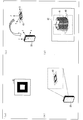
- FIG. 4 is a diagram illustrating a process of generating a three-dimensional object and a cross frame by the control unit 202 included in the mobile terminal 20.
- 4A shows the planar marker 40 viewed from the front
- FIG. 4B shows the imaging of the planar marker 40 by the mobile terminal 20
- FIG. 4D illustrates a process of calculating the attitude of the mobile terminal 20 based on the positional relationship with the mobile terminal 20.
- FIG. ) 42 and the planar marker 40 illustrates a process of calculating the attitude of the mobile terminal 20 based on the positional relationship with the mobile terminal 20.
- FIG. ) 42 and the planar marker 40 illustrates a process of calculating the attitude of the mobile terminal 20 based on the positional relationship with the mobile terminal 20.
- the plane marker 40 in this embodiment has the square pattern attached to the mount formed in the square.
- the shape of the mount and the pattern attached to the mount in the present invention are not limited to this, and a triangular pattern may be attached to a square mount, or a rectangular pattern may be attached to a rectangular mount. It may be attached, or a circular pattern may be attached to a circular mount.
- the material of the mount is not particularly limited, and for example, it may be formed using plastic, or may be formed using metal.
- a coordinate system (marker coordinate system) is calculated in which the horizontal direction along the mount of the flat marker 40 is the X axis, the vertical direction is the Y axis, and the direction orthogonal to the mount is the Z axis.
- the control unit 202 uses the center of a lens (not shown) included in the camera 201 as the origin, and the short direction of the mobile terminal 20 is the x axis and the long direction is the y axis. And a coordinate system (camera coordinate system) in which the thickness direction is the z-axis.
- the control unit 202 calculates the attitude relationship between the mobile terminal 20 and the planar marker 40 from the degree of coincidence between the camera coordinate system and the calculated marker coordinate system.
- control unit 202 determines whether or not the x-axis of the camera coordinate system and the X-axis of the marker coordinate system are parallel, and if not parallel, calculates the deviation from the parallel position.
- the horizontal positional relationship between the mobile terminal 20 and the flat marker 40 is calculated.
- control unit 202 determines whether or not the y-axis of the camera coordinate system and the Y-axis of the marker coordinate system are parallel.
- the posture relation in the vertical direction between 20 and the plane marker 40 is calculated. The calculation of the positional relationship and the posture relationship may be realized by appropriately using a well-known technique, and is not limited to the above method.
- control unit 202 determines whether or not the z-axis of the camera coordinate system and the Z-axis of the marker coordinate system overlap with each other, and calculates the deviation from the overlapping position when not overlapping, A horizontal posture relationship with the flat marker 40 is calculated.
- the control unit 202 determines the distance between the mobile terminal 20 and the planar marker 40 based on the size of the captured planar marker 40 and the like. Is calculated.
- the control unit 202 calculates the attitude of the mobile terminal 20 as described above. The calculation of the positional relationship and the posture relationship may be realized by appropriately using a well-known technique, and is not limited to the above method.
- control unit 202 generates the three-dimensional object 41 based on the plane marker 40.
- the generated three-dimensional object 41 preferably has anisotropy. Since the three-dimensional object 41 has anisotropy, the user can easily recognize the inclination of the three-dimensional object 41 displayed on the display unit 104.
- the anisotropic solid object 41 is preferably an object having a columnar solid shape (columnar object), for example, and is preferably a columnar object having a cross-shaped bottom surface (cross-shaped surface).
- the three-dimensional object 41 preferably has a longitudinal axis in a direction orthogonal to the planar marker 40. According to this, the user can more easily recognize the inclination of the three-dimensional object 41 displayed on the display unit 104.
- the user can change the inclination of the three-dimensional object 41 displayed on the display unit 104 as compared to, for example, the case where the three-dimensional object 41 is an object having a cone-shaped three-dimensional shape. It can be grasped more accurately.
- the solid object 41 has a cross-shaped columnar object, the user can easily grasp the center of the solid object 41. Thus, the user can more easily align the display device 10 and the wall hanging bracket 30 in the three-dimensional space.
- control unit 202 has a cross shape in the direction along the X axis and the Y axis of the marker coordinate system and has a height in the Z axis direction. 41 is generated.
- control unit 202 has a cross frame 42 in which a cross line is surrounded by a square frame in a direction along the x-axis and the y-axis of the camera coordinate system according to the distance between the mobile terminal 20 and the flat marker 40. Generate with For example, if the distance between the mobile terminal 20 and the flat marker 40 is long, the control unit 202 generates a large cross frame 42, and if the distance is short, generates a small cross frame 42. Good.
- the control unit 102 included in the display device 10 shows the three-dimensional object 41 generated by the control unit 202 included in the mobile terminal, the cross frame 42, and the planar marker 40 captured by the camera 201 as illustrated in FIG. And displayed on the display unit 104.
- the display system 1 can present to the user the orientation of the mobile terminal 20 with respect to the flat marker 40, that is, the orientation of the display device 10 with respect to the wall hanging bracket 30 in an easy-to-understand manner.
- the user can easily grasp the posture of the display device 10 with respect to the wall hanging bracket 30 by the plane marker 40, the three-dimensional object 41, and the cross frame 42 displayed on the display unit 104.
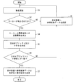
- FIG. 5 is a flowchart showing the flow of the attachment process of the display system 1 during the attachment operation of the display device 10 to the wall hanging bracket 30.
- step S1 when the display system 1 transitions to the attachment mode, the mobile terminal 20 starts imaging with the camera 201 (step S1).
- control unit 202 determines whether or not the planar marker 40 is detected from the image represented by the acquired image data (step S2).
- control unit 202 transmits the image data to the display device 10 via the wireless communication unit 205 (step S3), and again the camera.
- the imaging by 201 is controlled. That is, control unit 202 repeats the operations of steps S1 to S3 until planar marker 40 is detected from the captured image (YES in step S2).
- the control unit 202 calculates the attitude of the mobile terminal 20 with respect to the detected planar marker 40 (step S4), and the three-dimensional object 41 and a cross frame 42 are generated (step S5). Further, the reference image is generated by combining the generated solid object 41 and the cross frame 42 with the image captured by the camera 201.
- control unit 202 determines whether or not the length in the cross direction of the cross surface of the generated solid object 41 matches the length of the cross line in the cross frame 42 (step S6).
- the control unit 202 transmits the reference image data representing the reference image to the wireless communication unit 205. To the display device 10 (step S3), and the imaging by the camera 201 is controlled again. That is, the control unit 202 repeats the operations of steps S1 to S6 until the length of the cross direction of the cross surface of the three-dimensional object 41 matches the length of the cross line of the cross frame 42 (YES in step S6).
- step S6 When the length of the cross direction of the cross surface of the three-dimensional object 41 matches the length of the cross line of the cross frame 42 (YES in step S6), that is, the size of the cross frame 42 and the size of the bottom surface of the three-dimensional object 41 If they match, the control unit 202 transmits the reference image data together with the attachment completion information indicating that the attachment is completed to the display device 10 via the wireless communication unit 205 (step S7).
- step S7 The determination of the coincidence of the size of the cross surface of the three-dimensional object 41 and the size of the cross line of the cross frame 42 in step S6 will be described later.
- the display device 10 When the display device 10 acquires the attachment completion information from the mobile terminal 20, the display device 10 notifies the user that the attachment of the display device 10 to the wall hanging bracket 30 is completed. The notification of the completion of attachment will be described later.
- the display system 1 may transition to the attachment mode in accordance with a user instruction input from a remote controller (not shown) that operates the display device 10, but the present invention is not limited to this.
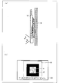
- FIG. 6 is an overview diagram showing an example of the posture relationship between the display device 10 and the wall hanging bracket 30.
- 6A shows an example of the posture of the display device 10 with respect to the wall hanging bracket 30, and
- FIG. 6B shows the posture relationship between the display device 10 and the wall hanging bracket 30 displayed on the display unit 104.
- FIG. It is an example of the screen to represent.
- the posture of the display device 10 immediately after the start of the mounting work is not parallel to the front surface of the wall hanging bracket 30 as shown in FIG. At this time, a cross frame 42 having a size corresponding to the distance from the planar marker 40 to the portable terminal 20 is displayed on the display unit 104 as shown in FIG.
- the reference image data representing the reference image displayed on the display unit 104 is transmitted from the portable terminal 20 via the wireless communication unit 205 and acquired by the wireless communication unit 101 of the display device 10 illustrated in FIG. Is done.
- the control unit 102 of the display device 10 supplies the reference image data acquired via the wireless communication unit 101 to the image processing unit 103, and the image processing unit 103 displays an image represented by the supplied reference image data.
- the display unit 104 is driven. As a result, the plane marker 40, the solid object 41, and the cross frame 42 are displayed on the display unit 104 as shown in FIG.
- the display unit 104 indicates the posture relationship between the mobile terminal 20 and the planar marker 40 calculated by the control unit 202 in a state where the solid object 41 and the planar marker 40 overlap the planar marker 40. Is displayed. As shown in FIG. 6B, when the side surface of the three-dimensional object 41 displayed on the display unit 104 is visible, the user confirms that the display device 10 is not parallel to the wall hanging bracket 30. It is possible to visually recognize the display device 10 without removing the back side.
- the user moves the display device 10 so that the side surface of the three-dimensional object 41 displayed on the display unit 104 is not displayed (that is, only the cross surface of the three-dimensional object 41 is displayed).
- the display device 10 can be adjusted to a posture parallel to the wall mounting bracket 30.
- the size of the cross frame 42 can be evaluated by, for example, the length of the longer one of the two line segments that are orthogonal to each other constituting the cross frame 42. Alternatively, the evaluation can be made based on the diameter of the smallest circle including the cross frame 42.
- the size of the bottom surface of the cruciform of the three-dimensional object can be evaluated by, for example, the length of the longer one of the two orthogonal bands constituting the bottom surface. Alternatively, it can be evaluated by the diameter of the smallest circle including the bottom of the cross shape.
- FIG. 7 is an overview diagram showing another example of the positional relationship between the display device 10 and the wall-mounted metal fitting 30.
- FIG. 7A shows another example of the posture of the display device 10 with respect to the wall hanging bracket 30, and
- FIG. 7B shows the posture of the display device 10 and the wall hanging bracket 30 displayed on the display unit 104. It is another example of the screen showing a relationship.
- FIG. 7B only the cross frame 42 having a size corresponding to the distance from the plane marker 40 to the mobile terminal 20 and the cross surface are displayed on the display unit 104 (that is, as shown in FIG. 7B).
- the solid object 41 and the plane marker 40 are displayed.
- the solid object 41 represents that the display device 10 and the wall hanging bracket 30 are in a parallel posture relationship.
- the user moves the display device 10 so that the cross line of the cross frame 42 and the cross surface of the three-dimensional object 41 overlap each other. Horizontal displacement can be adjusted.
- the display device 10 After performing the parallel posture alignment and the alignment, the display device 10 is overlapped with the wall hanging bracket 30 while maintaining the parallel posture of the display device 10 with respect to the wall hanging bracket 30 and the vertical and horizontal positions. This completes the installation work.
- a display screen of the display unit 104 according to the distance relationship between the display device 10 and the wall hanging bracket 30 when the display device 10 is brought close to the wall hanging bracket 30 will be described with reference to FIG.
- FIG. 8 is a diagram illustrating an example of a screen representing the distance relationship between the display device 10 and the wall hanging bracket 30 and the distance relationship between the display device 10 and the wall hanging bracket 30 displayed on the display unit 104.
- FIG. 8A shows a state where the distance between the display device 10 and the wall-mounting metal fitting 30 is long
- FIG. 8B shows a state where the distance between the display device 10 and the wall-mounting metal fitting 30 is short.
- FIG. 8C shows a state in which the display device 10 and the wall hanging bracket 30 are overlapped (attached).
- the cross frame 42 is displayed on the entire display screen of the display unit 104 as shown in FIG. 40 is displayed small.
- the cross frame 42 displayed on the display unit 104 becomes smaller as shown in FIG. 8B, and on the contrary, the plane displayed on the display unit 104.
- the marker 40 becomes larger.
- the flat marker 40 is displayed on the entire display unit 104, whereas the cross frame 42 is displayed in a small size.
- the length of the cross line of the cross frame 42 matches the length of the cross surface of the solid object 41 in the cross direction.
- the length of the cross line of the cross frame 42 displayed on the display unit 104 is the length in the cross direction of the cross surface of the three-dimensional object 41.
- the control unit 202 determines whether or not they match, that is, whether or not the display device 10 and the wall hanging bracket 30 are in a state of overlapping.
- FIG. 9 is a diagram illustrating a state in which the display device 10 has been attached to the wall mounting bracket 30.
- FIG. 9A shows a state in which when the attachment of the display device 10 to the wall mounting bracket 30 is completed, a sound indicating that the attachment is completed is output from the display device 10, and
- FIG. ) Shows a state in which an OSD image indicating that the attachment is completed is displayed on the display unit 104 when the attachment of the display device 10 to the wall hanging bracket 30 is completed.
- control unit 102 When the control unit 102 acquires the attachment completion information supplied from the control unit 202 included in the portable terminal 20 in step S7 in the above-described attachment process via the wireless communication unit 101, the control unit 102 attaches the display device 10 to the wall hanging bracket 30. Notify the user of completion.
- the control unit 102 outputs a sound indicating that the attachment is completed from an audio output unit (not shown) included in the display device 10, thereby attaching the control unit 102.
- the user may be notified that the process has been completed.
- the voice output from the voice output unit may be a voice of a person telling that the attachment is completed, or music indicating that the attachment is completed.
- control unit 102 superimposes the planar marker 40, the solid object 41, and the cross frame 42 on the display unit 104 to indicate that the attachment is completed (see FIG. 9B).
- the user may be informed by displaying “the position of the TV and the metal fitting has been matched” in 9 (b).
- the display system 1 can notify that the relative position of the display device 10 with respect to the wall hanging bracket 30 matches a predetermined relative position (a position where the wall hanging bracket 30 exists). Accordingly, the user can confirm that the relative position of the display device 10 with respect to the wall mounting bracket 30 matches the position where the wall mounting bracket 30 exists, that is, the positions of the display device 10 and the wall mounting bracket 30 match. Can make it easier.
- the user can easily know that the attachment is completed by receiving a notification that the attachment of the display device 10 to the wall mounting bracket 30 is completed.
- the configuration in which the size of the flat marker 40 and the cross frame 42 displayed on the display unit 104 is changed according to the distance between the display device 10 and the wall hanging bracket 30 has been described as an example.
- the present invention is not limited to this.
- the color of at least one of the planar marker 40, the three-dimensional object 41, and the cross frame 42 displayed on the display unit 104 changes according to the distance between the display device 10 and the wall hanging bracket 30.
- a configuration may be adopted.
- At least one of the color of the plane marker 40, the three-dimensional object 41, and the cross frame 42 displayed on the display unit 104 is red, yellow, blue It is good also as a structure which changes in order.
- the size of the crosshair can be evaluated by, for example, the length of the longer one of the two line segments that are orthogonal to each other constituting the crosshair. Or it can evaluate by the diameter of the minimum circle
- the size of the cross-shaped bottom surface can be evaluated by, for example, the length of the longer one of the two orthogonal bands constituting the bottom surface. Alternatively, it can be evaluated by the diameter of the smallest circle including the bottom surface of the cross shape.
- FIG. 10 is a view showing the back surface of the display device 10.
- FIG. 10A is an overview diagram showing the back surface of the display device 10
- FIG. 10B is an overview diagram of the back surface of the display device 10 when the storage unit 12 is removed from the display device 10. .
- a storage unit 12 for storing the mobile terminal 20 is provided on the back surface of the display device 10.
- the storage unit 12 is formed such that the camera 201 of the mobile terminal 20 is exposed from the storage unit 12, that is, does not cover the camera 201 of the mobile terminal 20.
- the camera 201 can capture an image in a direction orthogonal to the back surface of the display device 10 by being stored in the storage unit 12.
- the storage unit 12 is preferably configured to be removable from the display device 10 by sliding along the back surface of the display device 10.
- the storage unit 12 may be configured so that it can be pulled out in the short direction of the display device 10 as shown in FIG. Since the storage unit 12 can be removed by being pulled out from the display device 10, the portable terminal 20 can be easily detached from the display device 10 even after the display device 10 is attached to the wall-mounting bracket 30.
- the storage unit 12 has a surface exposed to the back side of the display device 10 as shown in FIG. 10B after the mobile terminal 20 is taken out after the display device 10 is attached to the wall mounting bracket 30. It is preferable that the display device 10 is configured to be attachable to the display device 10 in an inverted state with respect to the work for attaching the display device 10 to the wall hanging bracket 30. According to this configuration, the storage unit 12 that can store the mobile terminal 20 can be realized without deteriorating the design of the display device 10.
- the display system 1 is configured by the display device 10 and the mobile terminal 20 has been described as an example, but the present invention is not limited to this.
- a configuration in which the mobile terminal 20 is included in the display device 10 can be employed.
- the display device 10 includes the camera 201 and the control unit 202.
- the display device 10 can execute all the processes described above in the display device 10.
- FIG. 11 is a view showing the back surface of the display device 10.
- FIG. 11A is an overview diagram showing the back surface of the display device 10
- FIG. 11B is an overview diagram of the back surface of the display device 10 when the storage unit 12 is removed from the display device 10. .
- the display system 1 according to the present modification has the same configuration as the display system 1 according to the present embodiment, except that the storage unit 13 that stores the mobile terminal 20 is an external holder. .
- a storage unit 13 for storing the mobile terminal 20 is attached to the back surface of the display device 10.
- the storage unit 13 is formed so that the camera 201 of the mobile terminal 20 is exposed from the storage unit 12, that is, does not cover the camera 201 of the mobile terminal 20.
- the camera 201 can capture an image in a direction orthogonal to the back surface of the display device 10 by being stored in the storage unit 12.
- the storage unit 13 is configured to be removable from the display device 10. Specifically, the storage unit 13 is configured to be hung in the short direction of the display device 10 as shown in FIG. Since the storage unit 13 can be removed by pulling it up from the display device 10, the portable terminal 20 can be easily detached from the display device 10 even after the display device 10 is attached to the wall-mounting bracket 30. Thereby, the storage unit 13 that can store the mobile terminal 20 without impairing the design of the display device 10 can be realized.
- FIG. 12 is an overview diagram showing a display system 1 according to another modification of the present embodiment.
- the display system 1 according to this modification has the same configuration as the display system 1 according to the present embodiment except that the USB wireless adapter 14 is connected to the display device 10.
- the display device 10 when the display device 10 does not include the wireless communication unit 101, for example, by connecting a module having a wireless communication function to the display device 10, the mobile terminal 20 and the display device A configuration for realizing wireless communication with 10 can also be employed. Specifically, as shown in FIG. 12, a USB wireless adapter 14 having a wireless communication function is connected to a USB terminal (not shown) provided in the display device 10, so that the portable terminal 20 and the display device 10 are connected. An example of realizing wireless communication can be given.
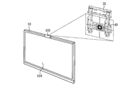
- FIG. 13 is an overview diagram showing a display system 1 according to Modification Example 3 of the present embodiment
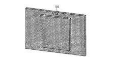
- FIG. 14 is an overview diagram showing a back surface of the display device 10 according to Modification Example 3 of the embodiment.
- the display device 10 includes a camera 105 on the display device 10. Further, the camera 105 of the display device 10 faces the back side of the display device 10 as shown in FIG. As described above, by using the camera 105 facing the back side of the display device 10, it is possible to capture a direction orthogonal to the back side of the display device 10.
- the camera 105 is a camera that performs the same operation as the camera 201 described above.
- the display device 10 according to this modification includes the control unit 202 described above.
- FIG. 15 is a schematic view showing the back surface of the display device 10 according to the third modification of the present embodiment.
- FIG. 15A shows a state in which the camera 105 faces the back surface of the display device 10.
- B shows a state where the direction of the camera 105 is changed, and
- c in the same figure shows a state where the camera 105 faces the front surface of the display device 10.
- the camera 105 of the display device 10 can change the orientation of the camera 105 as shown in FIG. Therefore, the direction of the camera 105 is set not only on the back side of the display device 10 as shown in FIG. 15A but also on the front side of the display device 10 as shown in FIG. be able to.
- the camera 105 of the display device 10 is a movable camera that can change the direction of the camera 105.
- the camera can be used for other purposes (for example, a camera for a video phone) without impairing the design of the display device 10.
- the installation position of the camera 105 is not limited to the upper part of the display apparatus 10, For example, a side part may be sufficient.
- the camera 105 is not limited to a movable camera, and may be a fixed camera.
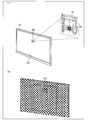
- FIG. 16 is a schematic view showing a display system 1 according to another modification of the present embodiment.
- FIG. 16A shows the front surface of the display device 10
- FIG. 16B shows the display device 10. The back is shown.
- the camera 105 is fixed to the back side of the display device 10.
- the camera 105 according to the present invention may be a camera fixed to the display device 10.
- the display device 10 when the display device 10 includes the camera 105 and the control unit 202, the display device 10 performs all the above-described processing (processing performed by the camera 201 and the control unit 202 of the mobile terminal 20) in the display device 10. Can be executed.
- a CCD camera Charge Coupled Device camera
- the camera 105 for example, a CCD camera (Charge Coupled Device camera) or the like can be used.
- Emodiment 2 In the first embodiment, the configuration in which the control unit 202 sequentially generates a three-dimensional object and a cross frame according to image data sequentially supplied from the camera 201 has been described. However, the object generated by the control unit 202 of the display device 10 according to the present invention is not limited to a three-dimensional object.
- an image generation apparatus according to another embodiment (Embodiment 2) of the present invention will be described with reference to FIGS. 17 to 19. In the present embodiment, the description will focus on the operation of the control unit 202 that performs processing different from that of the first embodiment.
- FIG. 17 is a diagram illustrating a process of generating a planar object and a cross frame by the control unit 202 included in the mobile terminal 20 according to the present embodiment.
- 17A shows the planar marker 40 as viewed from the front
- FIG. 17B shows the imaging of the planar marker 40 by the portable terminal
- FIG. 17C shows the planar marker 40 and the portable terminal.
- 20 shows a process of calculating the attitude of the mobile terminal 20 based on the positional relationship with the display 20
- FIG. 4D shows a planar object 41 ′ displayed on the display unit 104 of the display device 10 according to the present embodiment, a cross frame (Crosshair) 42 'and the planar marker 40 are shown.
- the planar marker 40 in this embodiment has the square pattern attached to the mount formed in the square.
- the shape of the mount in the present invention and the pattern attached to the mount are not limited to this, and a triangular pattern may be attached to a square mount, or a rectangular pattern is attached to a rectangular mount. It may be attached, or a circular pattern may be attached to a circular mount.
- the material of the mount is not particularly limited, and for example, it may be formed using plastic, or may be formed using metal.
- a coordinate system (marker coordinate system) is calculated in which the horizontal direction along the mount of the flat marker 40 is the X axis, the vertical direction is the Y axis, and the direction orthogonal to the mount is the Z axis.
- the control unit 202 uses the center of a lens (not shown) included in the camera 201 as the origin, and the short direction of the mobile terminal 20 is the x axis and the long direction is the y axis. And a coordinate system (camera coordinate system) in which the thickness direction is the z-axis.
- the control unit 202 calculates the attitude relationship between the mobile terminal 20 and the planar marker 40 from the degree of coincidence between the camera coordinate system and the calculated marker coordinate system.
- control unit 202 determines whether or not the x-axis of the camera coordinate system and the X-axis of the marker coordinate system are parallel, and if not parallel, calculates the deviation from the parallel position.
- the horizontal positional relationship between the mobile terminal 20 and the flat marker 40 is calculated.
- control unit 202 determines whether or not the y-axis of the camera coordinate system and the Y-axis of the marker coordinate system are parallel.
- the posture relation in the vertical direction between 20 and the plane marker 40 is calculated. The calculation of the positional relationship and the posture relationship may be realized by appropriately using a well-known technique, and is not limited to the above method.
- control unit 202 determines whether or not the z-axis of the camera coordinate system and the Z-axis of the marker coordinate system overlap with each other, and calculates the deviation from the overlapping position when not overlapping, A horizontal posture relationship with the flat marker 40 is calculated.
- the control unit 202 determines the distance between the mobile terminal 20 and the planar marker 40 based on the size of the captured planar marker 40 and the like. Is calculated.
- the control unit 202 calculates the attitude of the mobile terminal 20 as described above. The calculation of the positional relationship and the posture relationship may be realized by appropriately using a well-known technique, and is not limited to the above method.
- control unit 202 generates a planar object 41 ′ based on the planar marker 40 (that is, the position is fixed with respect to the planar marker 40).
- the shape of the planar object 41 ′ is not particularly limited, but is preferably a cross-shaped planar object as shown in FIG.
- the planar object 41 ' has a cross shape, the user can easily grasp the center of the planar object 41'.
- the user can more easily align the display device 10 and the wall hanging bracket 30 in the three-dimensional space.
- control unit 202 generates a planar object 41 'having a cross shape in the direction along the X axis and the Y axis of the marker coordinate system.
- control unit 202 generates a cross frame 42 ′ in which a cross line is surrounded by a square frame in a direction along the x axis and the y axis of the marker coordinate system with a size larger than that of the planar object 41 ′.
- the control unit 102 included in the display device 10 displays the planar object 41 ′, the cross frame 42 ′ generated by the control unit 202 included in the mobile terminal, and the planar marker 40 captured by the camera 201 in FIG. As shown, it is displayed on the display unit 104.
- the display system 1 can present to the user the orientation of the mobile terminal 20 with respect to the flat marker 40, that is, the orientation of the display device 10 with respect to the wall hanging bracket 30 in an easy-to-understand manner.
- the user can easily grasp the posture of the display device 10 with respect to the wall hanging bracket 30 by the plane marker 40, the plane object 41 ', and the cross frame 42' displayed on the display unit 104.
- FIG. 18 is an overview diagram showing an example of the posture relationship between the display device 10 and the wall-mounted metal fitting 30.
- FIG. 18A shows an example of the posture of the display device 10 with respect to the wall hanging bracket 30, and
- FIG. 18B shows the posture relationship between the display device 10 and the wall hanging bracket 30 displayed on the display unit 104. It is an example of a screen.
- the posture of the display device 10 immediately after the start of the mounting operation is not parallel to the front surface of the wall hanging bracket 30 as shown in FIG. At this time, as shown in FIG. 18B, a planar object 41 ′ and a cross frame 42 ′ are displayed on the display unit 104.
- reference image data representing a reference image displayed on the display unit 104 is transmitted from the portable terminal 20 via the wireless communication unit 205 and acquired by the wireless communication unit 101 of the display device 10.
- the control unit 102 of the display device 10 supplies the reference image data acquired via the wireless communication unit 101 to the image processing unit 103, and the image processing unit 103 displays an image represented by the supplied reference image data.
- the display unit 104 is driven. Thereby, the plane marker 40, the plane object 41 ', and the cross frame 42' are displayed on the display unit 104 as shown in FIG.
- the display unit 104 is calculated by the control unit 202 in a state where the plane object 41 ′, the plane marker 40, and the cross frame 42 ′ overlap the plane marker 40 with the plane object 41 ′ and the cross frame 42 ′. It is displayed so as to represent the posture relationship between the mobile terminal 20 and the flat marker 40. As shown in FIG. 18B, the planar object 41 ′ and the cross frame 42 ′ displayed on the display unit 104 appear to be tilted (that is, the angle formed by the two lines forming the cross line in the cross frame is 90). If not, the user can visually recognize that the display device 10 is not parallel to the wall mount 30 without removing the back side of the display device 10.
- the user moves the display device 10 so that the planar object 41 ′ and the cross frame 42 ′ displayed on the display unit 104 are tilted with respect to the wall hanging bracket 30, thereby moving the display device 10 to the wall hanging bracket 30. It can be adjusted to a parallel posture.
- the size of the cross shape of the planar object 41 ′ can be evaluated by, for example, the length of the longer one of the two orthogonal bands constituting the cross shape. Alternatively, it can be evaluated by the diameter of the smallest circle including the cross.
- FIG. 19 is an overview diagram illustrating another example of the positional relationship between the display device 10 and the wall hanging bracket 30.
- FIG. 19A shows another example of the posture of the display device 10 with respect to the wall hanging bracket 30, and
- FIG. 19B shows the posture relationship between the display device 10 and the wall hanging bracket 30 displayed on the display unit 104. It is another example of the screen showing.
- the display unit 104 includes a plane object 41 ′ and a cross frame 42 ′ indicating that the display device 10 and the wall hanging bracket 30 are in a parallel posture relationship, A marker 40 is displayed.
- the user can see the cross line of the cross frame 42 ′ and the cross surface of the plane object 41 ′ in the center of the display unit 104, and the frame of the display unit 104.
- the display device 10 By moving the display device 10 so as to be parallel to the vertical direction, it is possible to adjust the vertical and horizontal shifts of the display device 10 with respect to the wall mount 30.
- Each block of the display device 10 and the portable terminal 20 may be realized by hardware by a logic circuit formed on an integrated circuit (IC chip), or by software using a CPU (Central Processing Unit). It may be realized.
- IC chip integrated circuit
- CPU Central Processing Unit
- the display device 10 and the mobile terminal 20 include a CPU that executes instructions of a program that realizes each function, a ROM (Read Only Memory) that stores the program, and a RAM (Random Access Memory) that expands the program. And a storage device (recording medium) such as a memory for storing the program and various data.
- the object of the present invention is to record the program code (execution format program, intermediate code program, source program) of the control program for the display device 10 and the mobile terminal 20 that is software for realizing the above-described functions so as to be read by a computer. This can also be achieved by supplying the recorded medium to the display device 10 and the portable terminal 20 and reading and executing the program code recorded on the recording medium by the computer (or CPU or MPU).
- Examples of the recording medium include tapes such as magnetic tapes and cassette tapes, magnetic disks such as floppy (registered trademark) disks / hard disks, and disks including optical disks such as CD-ROM / MO / MD / DVD / CD-R.
- IC cards including memory cards) / optical cards, semiconductor memories such as mask ROM / EPROM / EEPROM (registered trademark) / flash ROM, or PLD (Programmable logic device) and FPGA (Field Programmable Gate Logic circuits such as (Array) can be used.
- the program code may be supplied to the display device 10 and the portable terminal 20 via a communication network.
- the communication network is not particularly limited as long as it can transmit the program code.
- the Internet intranet, extranet, LAN, ISDN, VAN, CATV communication network, virtual private network (Virtual Private Network), telephone line network, mobile communication network, satellite communication network, etc. can be used.
- the transmission medium constituting the communication network may be any medium that can transmit the program code, and is not limited to a specific configuration or type.
- wired such as IEEE 1394, USB, power line carrier, cable TV line, telephone line, ADSL (Asymmetric Digital Subscriber Line) line, infrared rays such as IrDA and remote control, Bluetooth (registered trademark), IEEE 8021 wireless, HDR (High Data) Rate), NFC (Near Field Communication), DLNA (Digital Living Network Alliance), mobile phone network, satellite line, terrestrial digital network, and the like.
- wired such as IEEE 1394, USB, power line carrier, cable TV line, telephone line, ADSL (Asymmetric Digital Subscriber Line) line, infrared rays such as IrDA and remote control, Bluetooth (registered trademark), IEEE 8021 wireless, HDR (High Data) Rate), NFC (Near Field Communication), DLNA (Digital Living Network Alliance), mobile phone network, satellite line, terrestrial digital network, and the like.
- wired such as IEEE 1394, USB, power line carrier, cable TV line, telephone line, ADSL (Asymmetric Digital Subscriber Line) line, infrared rays such as IrDA and remote control
- the image generation device is referred to in order to perform alignment between the first object to which the camera is attached and the second object to which the planar marker is attached.
- the image generating apparatus for generating a reference image includes a combining unit that generates the reference image by combining the reference object with the original image captured by the camera, and the reference object is a three-dimensional representation represented by the reference image. In the space, the reference object is based on the plane marker.
- An image generation method of an image generation apparatus is a reference that is referred to in order to perform alignment between a first object to which a camera is attached and a second object to which a planar marker is attached.
- An image generation method of an image generation apparatus for generating an image comprising: a combining step of generating the reference image by combining a reference object with an original image captured by the camera, wherein the reference object is the reference In the three-dimensional space represented by the image, the reference object is based on the planar marker.
- the image generation apparatus can easily position the positional relationship between the first object and the second object by combining the reference object with the original image by the combining unit.
- the reference image that can be understood can be generated. Accordingly, the user can easily grasp the positional relationship between the first object and the second object in the three-dimensional space by referring to the reference image.
- the reference object is a three-dimensional object.
- the reference object is a three-dimensional object
- the user can position the first object and the second object in parallel. Can understand that it is not a relationship.
- the side surface of the three-dimensional object is not visible in the reference image (that is, only the upper surface is visible for the three-dimensional object in the reference image)
- the user can recognize the first object and the first object. It can be understood that the two objects are in a parallel positional relationship.
- the user can easily align the first object and the second object in a three-dimensional space by referring to the reference image.
- the user since the user does not need to look into the back surface of the first object in order to align the position of the first object and the second object, the user can perform the alignment more safely.
- the three-dimensional object is a columnar object.
- the user can set the inclination of the three-dimensional object more than, for example, when the three-dimensional object is a cone-shaped object. Accurately grasp.
- the user can more easily align the first object and the second object in the three-dimensional space.
- the three-dimensional object is a columnar object having a cross-shaped bottom surface.
- the three-dimensional object synthesized with the original image is a columnar object having a cross-shaped bottom surface
- the user can easily grasp the center of the three-dimensional object. Accordingly, the user can more easily align the first object and the second object in the three-dimensional space.
- the synthesizing unit synthesizes a cross line with a fixed inclination with respect to the contour of the reference image, in addition to the three-dimensional object, to the original image. It is preferable to generate a reference image.
- the user in the three-dimensional space represented by the reference image, the user is based on the cross line with a fixed inclination relative to the outline of the reference image and the solid marker based on the planar marker with the fixed inclination.
- the inclination relationship with the object can be easily grasped. Thereby, the user can further easily align the first object and the second object in the three-dimensional space.
- the size of the crosshairs in the reference image decreases as the distance between the camera and the planar marker decreases, and the distance between the camera and the planar marker.
- the distance preferably matches the size of the bottom surface of the three-dimensional object.
- the distance between the camera and the planar marker that is, the distance between the first object and the second object can be easily grasped by the cross line.
- the size of the crosshair can be evaluated by, for example, the length of the longer one of the two line segments that are orthogonal to each other constituting the crosshair.
- the size of the cross-shaped bottom surface can be evaluated by, for example, the length of the longer one of the two orthogonal bands constituting the bottom surface.
- the synthesizing unit includes the planar marker, the three-dimensional object, and the crosshairs according to a distance between the first object and the second object. It is preferable to change at least one of the colors.
- the image generation device when the crosshairs overlap the bottom surface of the solid object and the size of the crosshairs matches the size of the bottom surface of the solid object, It is preferable to notify that the relative position of the object with respect to the second object matches the predetermined relative position.
- the image generation device notifies that the relative position of the first object with respect to the second object matches the predetermined relative position.
- the user agrees that the relative position of the first object to the second object matches the predetermined relative position, that is, the positions of the first object and the second object match. You can make it easier.
- the reference object may be a plane object having a cross shape.
- the reference object is a plane object having a cross shape
- the user can easily grasp the center of the plane object.
- the planar object has a cross shape
- the user can easily grasp the posture of the first object with respect to the second object. Accordingly, the user can more easily align the first object and the second object in the three-dimensional space.
- the synthesizing unit synthesizes the reference image by synthesizing the crosshair fixed to the planar object with the original image in addition to the planar object. It may be generated.
- the user can easily grasp the inclination of the crosshair fixed with respect to the planar object in the three-dimensional space represented by the reference image.
- the posture of the first object can be grasped more easily.
- the user can further easily align the first object and the second object in the three-dimensional space.
- a display device is a display device including the image generation device and a display panel, the display device being the first object, and the display device being hooked.
- a reference image generated by the image generation device from the original image captured by the camera disposed on the back surface of the display device is displayed on the display panel, with the latching tool installed on the wall surface as the second object. It is characterized by that.
- the display device can present the positional relationship between the display device and the hooking tool to the user by displaying the reference image on the display panel.
- the user can easily perform alignment in the three-dimensional space between the display device and the hook by referring to the reference image displayed on the display panel.
- the user since the user does not need to look into the back surface of the display device in order to align the position of the display device and the latch, the user can more securely latch the display device on the latch. be able to.
- a television receiver comprising the display device, an electronic blackboard comprising the display device, and a digital signage comprising the display device are also included in the scope of the present invention.
- a portable information terminal is a portable information terminal including the above-described image generation device and the camera, and includes a display device attached to the back surface of the portable information terminal.
- the said portable information terminal can transmit the said reference image to the said display apparatus, in the said display apparatus, the positional relationship of the said display apparatus and the said latch is shown to the user. Can be presented.
- the user can easily perform alignment in the three-dimensional space between the display device and the hook by referring to the reference image displayed on the display device.
- the user since the user does not need to look into the back surface of the display device in order to align the position of the display device and the latch, the user can more securely latch the display device on the latch. be able to.
- a display system includes a portable information terminal including the above-described image generation device and the camera, and a display including a display device including a display panel that displays the reference image.
- the portable information terminal uses the camera with the display device as the first object, and a hook installed on a wall surface for hooking the display device as a second object.
- a reference image generated by the image generation device is transmitted from the captured original image to the display device, and the display device includes a storage unit for storing the portable information terminal on a back surface of the display device, and stores the storage image.
- the reference image transmitted from the portable information terminal stored in the unit is displayed on the display panel.
- the said display system displays the said reference image transmitted from the said portable information terminal stored in the storage part with which the said display apparatus is equipped on the said display panel with which the said display apparatus is equipped.
- the positional relationship between the display device and the hook can be presented to the user.
- the user can easily perform alignment in the three-dimensional space between the display device and the hook by referring to the reference image displayed on the display panel.
- the user since the user does not need to look into the back surface of the display device in order to align the position of the display device and the latch, the user can more securely latch the display device on the latch. be able to.
- the storage portion is slidably attached along the back surface of the display device.
- the storage unit can be pulled out by sliding along the back surface of the display device, the portable device can be used even after the display device is hooked on the hook.
- the information terminal can be easily detached from the display device.
- a storage unit capable of storing the portable information terminal can be realized without impairing the design of the display device.
- the storage unit is hooked on the back surface of the display device.
- the storage unit can be removed by pulling up from the display device. Therefore, even after the display device is hooked on the hook, the portable information terminal can be It can be easily detached from the display device.
- a storage unit capable of storing the portable information terminal can be realized without impairing the design of the display device.
- a method for performing alignment is a method for performing alignment between a first object to which a camera is attached and a second object to which a planar marker is attached, An adjustment step of adjusting a relative position between the first object and the second object with reference to a reference image generated by combining a reference object with an original image captured by a camera, the reference
- the object is characterized in that it is a reference object based on the planar marker in the three-dimensional space represented by the reference image.
- the first object and the second object are referred to with reference to the reference image generated by combining the reference object based on the planar marker with the original image. Adjust the relative position to the object. As a result, the user can easily grasp the relative positional relationship between the first object and the second object in the three-dimensional space, and the relative position between the first object and the second object. Can be adjusted.
- the user can easily adjust the relative position of the first object and the second object in the three-dimensional space by referring to the reference image.
- the relative position can be adjusted more safely.
- a program for operating the image generation apparatus which is a program that causes a computer to function as each of the above-described units, and a computer-readable program that records these programs Recording media are also included in the scope of the present invention.
- the display device according to the present invention can be suitably applied to a television receiver, an electronic blackboard, and the like.
- the mobile terminal according to the present invention can be suitably applied to smartphones, mobile phones, digital video cameras, digital cameras, and the like.
- Display System 10 Display Device (First Object, Television Receiver, Electronic Blackboard) DESCRIPTION OF SYMBOLS 11 Attachment part 12, 13 Storage part 14 USB wireless adapter 20
- Portable terminal (portable information terminal) 30 Wall bracket (hanging fixture, second object) 40 Planar marker 41 Solid object (columnar object) 41 'Plane object 42 Cross frame (cross line) 42 'Cross frame (crosshair) 101 wireless communication unit 102 control unit 103 image processing unit 104 display unit (display panel) 105 Camera 201 Camera 202 Control Unit (Image Generation Device, Composition Unit) 203 Image processing unit 204 Display unit 205 Wireless communication unit
Landscapes
- Engineering & Computer Science (AREA)
- Multimedia (AREA)
- Signal Processing (AREA)
- Controls And Circuits For Display Device (AREA)
- Closed-Circuit Television Systems (AREA)
- Devices For Indicating Variable Information By Combining Individual Elements (AREA)
- Image Analysis (AREA)
- Image Processing (AREA)
- Processing Or Creating Images (AREA)
- Testing, Inspecting, Measuring Of Stereoscopic Televisions And Televisions (AREA)
Abstract
本発明の一態様に係る制御部(202)は、表示装置(10)と平面マーカー(40)が貼り付けられた壁掛け金具(30)との位置合わせを行うために参照される参照画像を、カメラ(201)により撮像された原画像に、参照画像が表す3次元空間において平面マーカー(40)に立脚した参照オブジェクトを合成することによって生成する。
Description
本発明は、画像生成装置、並びに、画像生成装置を備えた表示装置、携帯型情報端末、及び表示システムに関する。また、表示装置を備えるテレビジョン受像機、電子黒板、及びデジタルサイネージに関する。さらに、画像生成装置の画像生成方法、位置合わせを行う方法、画像生成装置を動作させるためのプログラム、及び、プログラムが記録されている記録媒体に関する。
近年、スマートフォン及び携帯電話などに代表される携帯端末との連携機能を搭載したテレビジョン受像機(以降、単にテレビとも呼称する)が普及してきている。このような携帯端末は、例えば、Wi-Fi(登録商標)などを利用した無線通信によってテレビを操作したり、テレビに表示される画像を携帯端末に表示したりすることができる。
また、近年、テレビの薄型化、及び軽量化が進んできていることに伴い、大型のテレビの持ち運びなどが比較的容易になってきている。これによって、ユーザは、テレビのレイアウトをより自由に決めることができるようになってきている。
しかしながら、このような薄型のテレビであっても、壁へ取り付ける際には、壁側の金具とテレビの金具とを正しく嵌合させる作業が必要となる。この作業は、テレビの裏側を覗き込んで金具の位置関係を確かめながら行う必要があるため、容易には行うことができない。また、テレビが大型である場合や重い場合などには、テレビの裏面を覗き込むことはますます困難となる。
このように、テレビの壁への取り付け作業時には、ユーザに大きな負担を強いることになる。また、金具が正しく嵌合していない場合、取り付けが終わったと思ったユーザがテレビを持つ力を緩めた際にテレビが落下してしまい、テレビが破損したりする可能性がある。
位置を合わせる技術として、例えば、特許文献1には、撮像された十字形部及び四角形部よりなるアライメントマークを含む画像を拡大してモニタ上に表示し、表示されたアライメントマークと予め記憶されている基準パターンとの位置合わせを行うことで、検出位置の設定精度を向上させる技術が開示されている。
また、特許文献2には、表示装置の本体部分に取り付けられた突起部と治具との接続箇所に隣接した位置で、突起部を治具に一旦仮置きでるようにすることによって、作業者の負担を軽減する技術が開示されている。
テレビを壁面に取り付ける際には、テレビを壁面に対して徐々に近づけつつ、壁面に沿った2次元方向の位置合わせを行う必要がある。すなわち、テレビを壁面に取り付ける作業は、3次元空間における位置合わせである。
この点について、特許文献1に記載の技術は、平面においての位置合わせに関する技術であり、3次元空間における位置合わせについては何ら記載されていない。このため、特許文献1に記載の技術を用い、モニタを見ながら作業を行ったとしても、テレビと壁面との距離を認識することが難しく、意図せずにテレビを壁面にぶつけてしまったり、テレビを落下させてしまったりすることもある。
また、特許文献2に記載の技術は、表示装置の治具への取り付け作業中に、作業者の負担を一旦軽減する技術であり、やはり表示装置と治具との位置合わせを容易には行うことができないという問題があった。
本発明は、上記の課題を解決するためになされたものであり、その主たる目的は、3次元空間における位置合わせを容易に行うことのできる表示装置を提供することにある。
本発明の一態様に係る画像生成装置は、上記の課題を解決するために、カメラが取り付けられた第1の物体と、平面マーカーが貼り付けられた第2の物体との位置合わせを行うために参照される参照画像を生成する画像生成装置において、上記カメラにより撮像された原画像に参照オブジェクトを合成することによって、上記参照画像を生成する合成手段を備え、上記参照オブジェクトは、上記参照画像が表す3次元空間において、上記平面マーカーに立脚した参照オブジェクトである、ことを特徴としている。
本発明の一態様に係る画像生成装置の画像生成方法は、上記の課題を解決するために、カメラが取り付けられた第1の物体と、平面マーカーが貼り付けられた第2の物体との位置合わせを行うために参照される参照画像を生成する画像生成装置の画像生成方法であって、上記カメラにより撮像された原画像に参照オブジェクトを合成することによって、上記参照画像を生成する合成工程を含み、上記参照オブジェクトは、上記参照画像が表す3次元空間において、上記平面マーカーに立脚した参照オブジェクトである、ことを特徴としている。
上記の構成によれば、上記画像生成装置は、上記合成手段によって上記原画像に上記参照オブジェクトを合成することにより、上記第1の物体と上記第2の物体との位置関係をユーザが容易に理解することのできる上記参照画像を生成することができる。これにより、ユーザは、上記参照画像を参照することによって、上記第1の物体と上記第2の物体との3次元空間における位置関係を容易に把握することができる。
これにより、ユーザは、上記第1の物体と上記第2の物体との位置を合わせるために当該第1の物体の背面を覗き込む必要がないため、より安全に位置合わせを行うことができる。
本発明の一態様に係る表示装置は、上記の課題を解決するために、上記画像生成装置と、表示パネルとを備える表示装置であって、当該表示装置を上記第1の物体とし、当該表示装置を掛止するために壁面に設置された掛止具を第2の物体として、当該表示装置の背面に配置された上記カメラにより撮像された原画像から上記画像生成装置により生成された参照画像を上記表示パネルに表示する、ことを特徴としている。
上記の構成によれば、上記表示装置は、上記表示パネルに上記参照画像を表示することによって、ユーザに、当該表示装置と、上記掛止具との位置関係を提示することができる。これによって、ユーザは、上記表示パネルに表示された参照画像を参照することにより、上記表示装置と上記掛止具との3次元空間における位置合わせを容易に行うことができる。
また、ユーザは、上記表示装置と上記掛止具との位置を合わせるために当該表示装置の背面を覗き込む必要がないため、上記表示装置の上記掛止具への掛止をより安全に行うことができる。
また、上記表示装置を備えていることを特徴とするテレビジョン受像機、上記表示装置を備えていることを特徴とする電子黒板、及び、上記表示装置を備えていることを特徴とするデジタルサイネージも、本発明の範疇に含まれる。
本発明の一態様に係る携帯型情報端末は、上記の課題を解決するために、上述の画像生成装置と、上記カメラとを備えた携帯型情報端末であって、当該携帯型情報端末が背面に取り付けられた表示装置を上記第1の物体とし、上記表示装置を掛止するために壁面に設置された掛止具を第2の物体として、上記カメラにより撮像された原画像から上記画像生成装置により生成された参照画像を上記表示装置に送信する、ことを特徴としている。
上記の構成によれば、上記携帯型情報端末は、上記表示装置に上記参照画像を送信することができるため、上記表示装置において、ユーザに、上記表示装置と上記掛止具との位置関係を提示することができる。これによって、ユーザは、上記表示装置に表示された参照画像を参照することにより、上記表示装置と上記掛止具との3次元空間における位置合わせを容易に行うことができる。
また、ユーザは、上記表示装置と上記掛止具との位置を合わせるために当該表示装置の背面を覗き込む必要がないため、上記表示装置の上記掛止具への掛止をより安全に行うことができる。
本発明の一態様に係る表示システムは、上記の課題を解決するために、上述の画像生成装置と、上記カメラとを備えた携帯型情報端末、及び、上記参照画像を表示する表示パネルを備えた表示装置を備えた表示システムであって、上記携帯型情報端末は、上記表示装置を上記第1の物体とし、上記表示装置を掛止するために壁面に設置された掛止具を第2の物体として、上記カメラにより撮像された原画像から上記画像生成装置により生成された参照画像を上記表示装置に送信し、上記表示装置は、上記携帯型情報端末を格納する格納部を当該表示装置の背面に備え、上記格納部に格納された上記携帯型情報端末から送信された上記参照画像を上記表示パネルに表示する、ことを特徴としている。
上記の構成によれば、上記表示システムは、上記表示装置の備える上記表示パネルに、上記表示装置の備える格納部に格納された上記携帯型情報端末から送信された上記参照画像を表示することによって、ユーザに、当該表示装置と、上記掛止具との位置関係を提示することができる。これによって、ユーザは、上記表示パネルに表示された参照画像を参照することにより、上記表示装置と上記掛止具との3次元空間における位置合わせを容易に行うことができる。
また、ユーザは、上記表示装置と上記掛止具との位置を合わせるために当該表示装置の背面を覗き込む必要がないため、上記表示装置の上記掛止具への掛止をより安全に行うことができる。
本発明の一態様に係る位置合わせを行う方法は、上記の課題を解決するために、カメラが取り付けられた第1の物体と、平面マーカーが貼り付けられた第2の物体との位置合わせを行う方法であって、上記カメラにより撮像された原画像に参照オブジェクトを合成することよって生成された参照画像を参照して、上記第1の物体と上記第2の物体との相対位置を調整する調整工程を含み、上記参照オブジェクトは、上記参照画像が表す3次元空間において、上記平面マーカーに立脚した参照オブジェクトである、ことを特徴としている。
上記の方法によれば、上記調整工程において、上記平面マーカーに立脚した参照オブジェクトを上記原画像に合成することによって生成された上記参照画像を参照して、上記第1の物体と上記第2の物体との相対位置を調整する。これにより、ユーザは、上記第1の物体と上記第2の物体との3次元空間における相対的な位置関係を容易に把握しつつ、上記第1の物体と上記第2の物体との相対位置を調整することができる。
したがって、ユーザは、上記参照画像を参照することによって、上記第1の物体と上記第2の物体との3次元空間における相対位置を容易に調整することができる。
また、ユーザは、上記第1の物体と上記第2の物体との位置を合わせるために当該第1の物体の背面を覗き込む必要がないため、より安全に相対位置を調整することができる。
また、本発明の一態様に係る画像生成装置を動作させるためのプログラムであって、コンピュータを上記の各手段として機能させることを特徴とするプログラム、及び、これらのプログラムを記録したコンピュータ読み取り可能な記録媒体も本発明の範疇に含まれる。
本発明の一態様に係る画像生成装置は、上記の課題を解決するために、カメラが取り付けられた第1の物体と、平面マーカーが貼り付けられた第2の物体との位置合わせを行うために参照される参照画像を生成する画像生成装置において、上記カメラにより撮像された原画像に参照オブジェクトを合成することによって、上記参照画像を生成する合成手段を備え、上記参照オブジェクトは、上記参照画像が表す3次元空間において、上記平面マーカーに立脚した参照オブジェクトである、ことを特徴としている。
本発明の一態様に係る画像生成装置の画像生成方法は、上記の課題を解決するために、カメラが取り付けられた第1の物体と、平面マーカーが貼り付けられた第2の物体との位置合わせを行うために参照される参照画像を生成する画像生成装置の画像生成方法であって、上記カメラにより撮像された原画像に参照オブジェクトを合成することによって、上記参照画像を生成する合成工程を含み、上記参照オブジェクトは、上記参照画像が表す3次元空間において、上記平面マーカーに立脚した参照オブジェクトである、ことを特徴としている。
また、本発明の一態様に係る位置合わせを行う方法は、上記の課題を解決するために、カメラが取り付けられた第1の物体と、平面マーカーが貼り付けられた第2の物体との位置合わせを行う方法であって、上記カメラにより撮像された原画像に参照オブジェクトを合成することよって生成された参照画像を参照して、上記第1の物体と上記第2の物体との相対位置を調整する調整工程を含み、上記参照オブジェクトは、上記参照画像が表す3次元空間において、上記平面マーカーに立脚した参照オブジェクトである、ことを特徴としている。
したがって、ユーザは、上記参照画像を参照することによって、上記第1の物体と上記第2の物体との3次元空間における位置合わせを容易に行うことができる。
[実施形態1]
本発明の一実施形態に係る画像生成装置について、図1から図10を参照して説明する。但し、この実施形態に記載されている構成は、特に特定的な記載がない限り、この発明の範囲をそれのみに限定する趣旨ではなく、単なる説明例に過ぎない。
本発明の一実施形態に係る画像生成装置について、図1から図10を参照して説明する。但し、この実施形態に記載されている構成は、特に特定的な記載がない限り、この発明の範囲をそれのみに限定する趣旨ではなく、単なる説明例に過ぎない。
なお、本実施形態では、画像生成装置が、表示装置と共に表示システムを構成する携帯端末(携帯型情報端末)に備えられている場合を例に挙げて説明するが、本発明はこれに限定されるものではなく、もちろ、表示装置に備えられている構成を採用してもよい。
〔表示システム〕
まず、本実施形態に係る表示システムについて、図2及び図3を参照して説明する。図2は、本実施形態に係る表示システム1と壁掛け金具30との関係を示す概観図である。図3は、本実施形態に係る表示装置10の背面を示す概観図である。
まず、本実施形態に係る表示システムについて、図2及び図3を参照して説明する。図2は、本実施形態に係る表示システム1と壁掛け金具30との関係を示す概観図である。図3は、本実施形態に係る表示装置10の背面を示す概観図である。
図2に示すように、本実施形態に係る表示システム1は、表示装置(第1の物体)10、及び、携帯端末20を備えている。また、表示システム1に含まれる表示装置10は、例えば壁などに設置された壁掛け金具(第2の物体、掛止具)30に取り付けることが可能となっている。さらに、壁掛け金具30には、図2に示すように、平面マーカー40が貼り付けられている。
図3に示すように、表示装置10の背面に設けられた格納部12に、携帯端末20が格納されている。また、表示装置10の背面には、壁掛け金具30に表示装置10を取り付けるための取付部11が設けられている。なお、携帯端末20の格納部12への格納、及び格納部12からの取り出しについては、後述する。
なお、本実施形態に係る表示装置10は、例えば、テレビジョン受像機によって実現することができるが、本発明はこれに限定されるものではなく、電子黒板、デジタルサイネージなどによって実現されてもよい。また、本実施形態に係る携帯端末は、例えば、スマートフォンによって実現することができるが、本発明はこれに限定されるものではなく、携帯電話、又はデジタルカメラなどによって実現されてもよい。
次に、表示システム1を構成する表示装置10、及び、携帯端末20について、図1を参照して説明する。図1は、本実施形態に係る表示システム1の構成の概略を示すブロック図である。
(携帯端末の構成)
まず、携帯端末20の構成について、図1を参照して説明する。図1に示すように、表示システム1を構成する携帯端末20は、カメラ201、制御部(合成手段、画像生成装置)202、画像処理部203、表示部204、及び、無線通信部205を備えている。
まず、携帯端末20の構成について、図1を参照して説明する。図1に示すように、表示システム1を構成する携帯端末20は、カメラ201、制御部(合成手段、画像生成装置)202、画像処理部203、表示部204、及び、無線通信部205を備えている。
制御部202は、携帯端末20の備える各部を制御する。また、制御部202は、カメラ201によって撮像された画像(原画像)に応じて制御を行う。なお、カメラ201によって撮像される画像は、静止画像であってもよいし、動画像であってもよい。なお、本実施形態では、画像が動画像である場合を例に挙げて説明する。
制御部202は、カメラ201によって撮像された画像を表す画像データをカメラ201から取得する。
また、制御部202は、カメラ201から画像データを取得すると、取得した画像データの表す画像から、平面マーカー40を検出する検出機能を備えている。この制御部202の備える検出機能は、例えば、予め所定の平面マーカー40のパターンとして指定されているパターンと同じパターンが、画像の表す3次元空間の何れの方向にカメラからどの程度離れているかを検出する、公知の技術によって実現されればよいが、本発明はこれに限定されるものではない。なお、平面マーカー40のパターンの指定は、携帯端末20を操作する操作部又はタッチパネル(何れも不図示)などによってされてもよいし、予め記憶部(不図示)に格納されているパターンによってされてもよい。
壁掛け金具30に設けられている平面マーカー40がカメラ201によって撮像されると、制御部202は、立体的なオブジェクト(以降、立体オブジェクトとも呼称する)(参照オブジェクト)を生成し、生成した立体オブジェクトを撮像された画像の表す3次元空間において平面マーカー40に立脚するように合成した参照画像を生成する。すなわち、本実施形態では、制御部202が、合成手段を備えた画像生成装置として機能する。
さらに、制御部202は、携帯端末20と平面マーカー40との距離を算出すると共に、算出した距離に応じた大きさの十字枠(十字線)であって、表示装置10を表す十字枠を生成し、参照画像と合成する。なお、十字枠は、参照画像の画郭に対する傾きが固定されている。
制御部202は、カメラ201から逐次供給される画像データに従って、立体オブジェクト、及び十字枠を順次生成する。なお、立体オブジェクト、及び十字枠の生成の詳細については、後述する。
制御部202は、生成した立体オブジェクト、十字枠、及び、カメラ201によって撮像された平面マーカー40を合成した参照画像を表す参照画像データを無線通信部205に供給する。
画像処理部203は、入力された画像データに対し、画像データの表す画像の大きさを表示部204の有する表示領域の大きさに合わせるように拡大又は縮小するスケーリング処理を施す。また、画像処理部203は、入力された画像データの表す画像を表示するように、表示部204を駆動する。また、画像処理部203は、表示部204に表示する画像データに対し、画質を調整する画質調整処理を施してもよい。
無線通信部205は、表示装置10と無線通信を行う。無線通信部205は、制御部202から供給された参照画像データを表示装置10に送信する。
なお、無線通信部205における無線通信は、例えば、赤外線通信、Wi-Fi、Bluetooth(登録商標)などによって実現することができるが、特に限定されるものではない。
(表示装置の構成)
次に、表示装置10の構成について、図1を参照して説明する。図1に示すように、表示システム1を構成する表示装置10は、無線通信部101、制御部102、画像処理部103、及び、表示部(表示パネル)104を備えている。
次に、表示装置10の構成について、図1を参照して説明する。図1に示すように、表示システム1を構成する表示装置10は、無線通信部101、制御部102、画像処理部103、及び、表示部(表示パネル)104を備えている。
無線通信部101は、携帯端末20と無線通信を行う。無線通信部205は、携帯端末20から送信される参照画像データを受信する。
なお、無線通信部205における無線通信は、例えば、赤外線通信、Wi-Fi、Bluetooth(登録商標)などによって実現することができるが、特に限定されるものではない。
制御部102は、表示装置10の備える各部を制御する。また、制御部102は、無線通信部205を介して携帯端末20から取得した参照画像データを画像処理部103に供給する。
画像処理部103は、入力された画像データの表す画像を表示するように表示部104を駆動する。また、入力された画像データに対し、画像データの表す画像の大きさを表示部104の有する表示領域の大きさに合わせるように拡大又は縮小するスケーリング処理を施す。また、画像処理部103は、入力された画像データの表す画像を表示するように、表示部104を駆動する。また、画像処理部103は、表示部104に表示する画像データに対し、画質を調整する画質調整処理を施してもよい。
画像処理部103は、制御部102から供給された参照画像データに対し、上述したスケーリング処理を施すと共に、参照画像データの表す参照画像を表示するように表示部104を駆動する。
具体的には、画像処理部103は、十字枠を、当該十字枠に含まれる十字の交点が表示部104の中心に表示されるよう表示部104を駆動する。また、画像処理部103は、立体オブジェクトを平面マーカー40に重畳して表示部104に表示する。なお、立体オブジェクト、十字枠、及び平面マーカー40の具体的な表示については、後述する。
〔立体オブジェクト、十字枠の生成〕
次に、携帯端末20の備える制御部202によって生成される参照画像が表す3次元空間における、立体オブジェクト、及び十字枠について、図4を参照して説明する。図4は、携帯端末20の備える制御部202による立体オブジェクト、及び十字枠の生成の過程を示す図である。図4の(a)は、正面から見た平面マーカー40を示し、図4の(b)は、携帯端末20による平面マーカー40の撮像を示し、図4の(c)は、平面マーカー40と携帯端末20との位置関係に基づく携帯端末20の姿勢の算出の過程を示し、図4の(d)は、表示装置10の備える表示部104に表示される立体オブジェクト41、十字枠(十字線)42、及び平面マーカー40を示している。
次に、携帯端末20の備える制御部202によって生成される参照画像が表す3次元空間における、立体オブジェクト、及び十字枠について、図4を参照して説明する。図4は、携帯端末20の備える制御部202による立体オブジェクト、及び十字枠の生成の過程を示す図である。図4の(a)は、正面から見た平面マーカー40を示し、図4の(b)は、携帯端末20による平面マーカー40の撮像を示し、図4の(c)は、平面マーカー40と携帯端末20との位置関係に基づく携帯端末20の姿勢の算出の過程を示し、図4の(d)は、表示装置10の備える表示部104に表示される立体オブジェクト41、十字枠(十字線)42、及び平面マーカー40を示している。
(マーカー)
図4の(a)に示すように、本実施形態における平面マーカー40は、正方形に形成された台紙に、正方形のパターンが付されている。なお、本発明における台紙の形状、及び台紙に付されるパターンはこれに限定されるものではなく、三角形のパターンが正方形の台紙に付されていてもよいし、長方形の台紙に長方形のパターンが付されていてもよいし、円形の台紙に円形のパターンが付されていてもよい。また、台紙の材質は特に限定されるものではなく、例えば、プラスチックを用いて形成されていてもよいし、金属を用いて形成されていてもよい。
図4の(a)に示すように、本実施形態における平面マーカー40は、正方形に形成された台紙に、正方形のパターンが付されている。なお、本発明における台紙の形状、及び台紙に付されるパターンはこれに限定されるものではなく、三角形のパターンが正方形の台紙に付されていてもよいし、長方形の台紙に長方形のパターンが付されていてもよいし、円形の台紙に円形のパターンが付されていてもよい。また、台紙の材質は特に限定されるものではなく、例えば、プラスチックを用いて形成されていてもよいし、金属を用いて形成されていてもよい。
(立体オブジェクト、十字枠)
また、図4の(b)に示すように、カメラ201によって平面マーカー40が撮像されると、制御部202は、図4の(c)に示すように、平面マーカー40のパターンの中心を原点として、平面マーカー40の台紙に沿った水平方向がX軸、鉛直方向がY軸、及び台紙に直交する方向がZ軸となる座標系(マーカー座標系)を算出する。
また、図4の(b)に示すように、カメラ201によって平面マーカー40が撮像されると、制御部202は、図4の(c)に示すように、平面マーカー40のパターンの中心を原点として、平面マーカー40の台紙に沿った水平方向がX軸、鉛直方向がY軸、及び台紙に直交する方向がZ軸となる座標系(マーカー座標系)を算出する。
なお、制御部202は、図4の(c)に示すように、カメラ201の備えるレンズ(不図示)の中心を原点として、携帯端末20の、短手方向をx軸、長手方向をy軸、及び厚さ方向がz軸となる座標系(カメラ座標系)を有している。
制御部202は、カメラ座標系と、算出したマーカー座標系との一致度から、携帯端末20と平面マーカー40との姿勢関係を算出する。
具体的には、制御部202は、カメラ座標系のx軸とマーカー座標系のX軸とが平行であるか否かを判定し、並行でない場合には平行位置からのずれを算出することで、携帯端末20と平面マーカー40との水平方向の位置関係を算出する。また、制御部202は、カメラ座標系のy軸とマーカー座標系のY軸とが平行であるか否かを判定し、並行でない場合には平行位置からのずれを算出することで、携帯端末20と平面マーカー40との鉛直方向の姿勢関係を算出する。なお、位置関係及び姿勢関係の算出は、周知の技術を適宜用いることによって実現されればよく、上記の方法に限定されるものではない。
さらに、制御部202は、カメラ座標系のz軸とマーカー座標系のZ軸とが重なるか否かを判定し、重ならない場合には重なる位置からのずれを算出することで、携帯端末20と平面マーカー40との水平方向の姿勢関係を算出する。また、制御部202は、カメラ座標系のz軸とマーカー座標系のZ軸とが重なる場合に、撮像された平面マーカー40の大きさなどに基づいて、携帯端末20と平面マーカー40との距離を算出する。制御部202は、上述のように、携帯端末20の姿勢を算出する。なお、位置関係及び姿勢関係の算出は、周知の技術を適宜用いることによって実現されればよく、上記の方法に限定されるものではない。
また、制御部202は、平面マーカー40に立脚した立体オブジェクト41を生成する。このとき、生成される立体オブジェクト41は、異方性を有することが好ましい。立体オブジェクト41が異方性を有することによって、ユーザは、表示部104に表示される立体オブジェクト41の傾きを容易に認識することができる。
異方性を有する立体オブジェクト41は、例えば、柱状の立体形状を有するオブジェクト(柱状オブジェクト)であることが好ましく、また、十字形の底面(十字面)を有する柱状オブジェクトであることが好ましい。なお、立体オブジェクト41は、平面マーカー40に直交する方向に長手軸を有していることが好ましい。これによれば、ユーザは、表示部104に表示される立体オブジェクト41の傾きをより容易に認識することができる。
立体オブジェクト41が柱状オブジェクトである場合、ユーザは、例えば立体オブジェクト41が錐状の立体形状を有するオブジェクトである場合と比較して、ユーザは、表示部104に表示される立体オブジェクト41の傾きをより正確に把握することができる。また、立体オブジェクト41が十字面を有する柱状オブジェクト場合には、ユーザは、立体オブジェクト41の中心を容易に把握することができる。これによって、ユーザは、表示装置10と壁掛け金具30との3次元空間における位置合わせをより容易に行うことができるようになる。
例えば、制御部202は、図4の(d)に示すように、マーカー座標系のX軸及びY軸に沿った方向に十字の形状を有し、Z軸方向に高さを持った立体オブジェクト41を生成する。
さらに、制御部202は、カメラ座標系のx軸及びy軸に沿った方向に十字線を正方形の枠で囲んだ十字枠42を、携帯端末20と平面マーカー40との距離に応じた大きさで生成する。制御部202は、例えば、携帯端末20と平面マーカー40との距離が長い場合には大きさの大きな十字枠42を生成し、距離が短い場合には大きさの小さな十字枠42を生成すればよい。
表示装置10の備える制御部102は、携帯端末の備える制御部202によって生成された立体オブジェクト41、十字枠42、及びカメラ201によって撮像された平面マーカー40を、図4の(d)に示すように、表示部104に表示する。これによって、表示システム1は、平面マーカー40に対する携帯端末20の姿勢、すなわち、壁掛け金具30に対する表示装置10の姿勢を、ユーザに分かりやすく提示することができる。
したがって、ユーザは、表示部104に表示された平面マーカー40、立体オブジェクト41、及び十字枠42によって、壁掛け金具30に対する表示装置10の姿勢を容易に把握することができる。
〔取付処理〕
次に、表示装置10の壁掛け金具30への取り付け作業時における、表示システム1の処理(取付処理)について、図5から図8を参照して説明する。図5は、表示装置10の壁掛け金具30への取り付け作業時における、表示システム1の取付処理の流れを示すフローチャートである。
次に、表示装置10の壁掛け金具30への取り付け作業時における、表示システム1の処理(取付処理)について、図5から図8を参照して説明する。図5は、表示装置10の壁掛け金具30への取り付け作業時における、表示システム1の取付処理の流れを示すフローチャートである。
図5に示すように、表示システム1が、取付モードに遷移すると、携帯端末20は、カメラ201による撮像を開始する(ステップS1)。
制御部202は、カメラ201によって撮像された画像を表す画像データを取得すると、取得した画像データの表す画像から平面マーカー40が検出されるか否かを判定する(ステップS2)。
カメラ201によって撮像された画像から平面マーカー40が検出されない場合(ステップS2においてNO)、制御部202は、画像データを無線通信部205を介して表示装置10に送信し(ステップS3)、再びカメラ201による撮像を制御する。つまり、制御部202は、撮像された画像から平面マーカー40が検出されるまで(ステップS2においてYES)、ステップS1~S3の動作を繰り返す。
カメラ201によって撮像された画像から平面マーカー40が検出された場合(ステップS2においてYES)、制御部202は、検出された平面マーカー40に対する携帯端末20の姿勢を算出し(ステップS4)、立体オブジェクト41、及び十字枠42を生成する(ステップS5)。また、カメラ201によって撮像された画像に、生成した立体オブジェクト41、及び十字枠42を合成することで参照画像を生成する。
次に、制御部202は、生成した立体オブジェクト41の十字面の十字方向の長さと、十字枠42の十字線の長さとが一致するか否かを判定する(ステップS6)。
立体オブジェクト41の十字面の十字方向の長さと十字枠42の十字線の長さとが一致しない場合(ステップS6においてNO)、制御部202は、参照画像を表す参照画像データを無線通信部205を介して表示装置10に送信し(ステップS3)、再びカメラ201による撮像を制御する。つまり、制御部202は、立体オブジェクト41の十字面の十字方向の長さと十字枠42の十字線の長さとが一致するまで(ステップS6においてYES)、ステップS1~S6の動作を繰り返す。
立体オブジェクト41の十字面の十字方向の長さと十字枠42の十字線の長さとが一致した場合(ステップS6においてYES)、すなわち、十字枠42のサイズと、立体オブジェクト41の底面のサイズとが一致した場合、制御部202は、参照画像データと共に、取り付けが完了した旨を示す取付完了情報とを併せて無線通信部205を介して表示装置10に送信する(ステップS7)。なお、ステップS6における、立体オブジェクト41の十字面のサイズ、及び、十字枠42の十字線のサイズの一致の判定については、後述する。
表示装置10は、携帯端末20から取付完了情報を取得すると、表示装置10の壁掛け金具30への取り付けが完了した旨をユーザに報知する。なお、取り付け完了の報知については後述する。
また、表示システム1は、例えば、表示装置10を操作するリモコン(不図示)などから入力されるユーザ指示によって取付モードへ遷移すればよいが、本発明はこれに限定されるものではない。例えば、携帯端末20の備える操作部又はタッチパネル(いずれも不図示)などから入力されるユーザ指示によって取付モードへ遷移する構成を採用してもよい。
〔取付作業の流れ〕
次に、上述した取付処理を機能させながら行う取付作業の流れについて、図6から図9を参照して説明する。
次に、上述した取付処理を機能させながら行う取付作業の流れについて、図6から図9を参照して説明する。
(平行姿勢合わせ)
まず、取付作業のうち、表示装置10の背面を壁掛け金具30の壁面取付面と平行な姿勢にする、平行姿勢合わせについて、図6を参照して説明する。図6は、表示装置10と壁掛け金具30との姿勢関係の一例を示す概観図である。図6の(a)は、壁掛け金具30に対する表示装置10の姿勢の一例を示し、図6の(b)は、表示部104に表示される、表示装置10と壁掛け金具30との姿勢関係を表す画面の一例である。
まず、取付作業のうち、表示装置10の背面を壁掛け金具30の壁面取付面と平行な姿勢にする、平行姿勢合わせについて、図6を参照して説明する。図6は、表示装置10と壁掛け金具30との姿勢関係の一例を示す概観図である。図6の(a)は、壁掛け金具30に対する表示装置10の姿勢の一例を示し、図6の(b)は、表示部104に表示される、表示装置10と壁掛け金具30との姿勢関係を表す画面の一例である。
取付作業を開始した直後における表示装置10の姿勢は、図6の(a)に示すように、壁掛け金具30の正面に対して平行でない。このとき、表示部104には、図6の(b)に示すように、平面マーカー40から携帯端末20までの距離に応じた大きさの十字枠42が表示される。
なお、表示部104に表示される参照画像を表す参照画像データは、無線通信部205を介して携帯端末20から送信され、図6の(a)に示す表示装置10の無線通信部101によって取得される。表示装置10の制御部102は、無線通信部101を介して取得した参照画像データを画像処理部103に供給し、画像処理部103は、供給された参照画像データが表す画像を表示するように表示部104を駆動する。これによって、表示部104に、図6の(b)に示すような、平面マーカー40、立体オブジェクト41、及び十字枠42が表示される。
また、表示部104には、立体オブジェクト41及び平面マーカー40が、平面マーカー40に立体オブジェクト41が重なった状態で、制御部202によって算出された携帯端末20と平面マーカー40との姿勢関係を表すように表示される。図6の(b)に示すように、表示部104に表示される立体オブジェクト41の側面が見えている場合、ユーザは、表示装置10が壁掛け金具30に対して平行になっていないことを、表示装置10の裏側を除かなくとも視覚的に認識することができる。
ユーザは、表示部104に表示されている立体オブジェクト41の側面が表示されなくなるように(すなわち、立体オブジェクト41の十字面のみが表示される状態となるように)表示装置10を動かすことによって、表示装置10を、壁掛け金具30に対して平行な姿勢に調整することができる。
なお、十字枠42のサイズは、例えば、当該十字枠42を構成する互いに直交する2本の線分のうち、長い方の線分の長さにより評価することができる。あるいは、十字枠42を包含する最小の円の直径により評価することができる。一方、立体オブジェクトの十字形の底面のサイズは、例えば、当該底面を構成する互いに直交する2本の帯のうち、長い方の帯の長さにより評価することができる。あるいは、十字形の底面を包含する最小の円の直径により評価することができる。
(位置合わせ)
次に、表示装置10の、壁掛け金具30に対する鉛直方向、及び水平方向のずれを調整する位置合わせについて、図7を参照して説明する。図7は、表示装置10と壁掛け金具30との位置関係の他の一例を示す概観図である。図7の(a)は、壁掛け金具30に対する表示装置10の姿勢の他の一例を示し、図7の(b)は、表示部104に表示される、表示装置10と壁掛け金具30との姿勢関係を表す画面の他の一例である。
次に、表示装置10の、壁掛け金具30に対する鉛直方向、及び水平方向のずれを調整する位置合わせについて、図7を参照して説明する。図7は、表示装置10と壁掛け金具30との位置関係の他の一例を示す概観図である。図7の(a)は、壁掛け金具30に対する表示装置10の姿勢の他の一例を示し、図7の(b)は、表示部104に表示される、表示装置10と壁掛け金具30との姿勢関係を表す画面の他の一例である。
表示装置10の姿勢を調整することによって表示装置10と壁掛け金具30とが平行な姿勢関係になった場合、次に、図7の(a)に示すように、表示装置10の、壁掛け金具30に対する鉛直方向、及び水平方向のずれを調整する位置合わせを行う。
このとき、表示部104には、図7の(b)に示すように、平面マーカー40から携帯端末20までの距離に応じた大きさの十字枠42と、十字面のみが表示された(つまり、表示装置10と壁掛け金具30とが平行な姿勢関係であることを表す)立体オブジェクト41と、平面マーカー40とが表示されている。
ユーザは、図7に示すように、十字枠42の十字線と、立体オブジェクト41の十字面とが重なるように表示装置10を動かすことによって、表示装置10の、壁掛け金具30に対する鉛直方向、及び水平方向のずれを調整することができる。
(取り付け)
平行姿勢合わせ、及び、位置合わせを行った後は、表示装置10の、壁掛け金具30に対する平行姿勢と、鉛直方向及び水平方向の位置とを維持したまま、表示装置10を壁掛け金具30と重ね合わせることによって、取付作業が完了する。
平行姿勢合わせ、及び、位置合わせを行った後は、表示装置10の、壁掛け金具30に対する平行姿勢と、鉛直方向及び水平方向の位置とを維持したまま、表示装置10を壁掛け金具30と重ね合わせることによって、取付作業が完了する。
表示装置10を壁掛け金具30に近づける際の、表示装置10と壁掛け金具30との距離関係に応じた表示部104の表示画面について、図8を参照して説明する。
図8は、表示装置10と壁掛け金具30との距離関係、及び、表示部104に表示される、表示装置10と壁掛け金具30との距離関係を表す画面の一例を示す図である。図8の(a)は、表示装置10と壁掛け金具30との距離が離れている状態を示し、図8の(b)は、表示装置10と壁掛け金具30との距離が近づいた状態を示し、図8の(c)は、表示装置10と壁掛け金具30とが重なった(取り付けられた)状態を示している。
表示装置10と壁掛け金具30との距離が離れている場合には、図8の(a)に示すように、十字枠42は表示部104の表示画面全体に表示されることに対し、平面マーカー40は小さく表示される。
表示装置10と壁掛け金具30との距離が近づくにつれて、図8の(b)に示すように、表示部104に表示される十字枠42は小さくなり、反対に、表示部104に表示される平面マーカー40は大きくなる。
表示装置10と壁掛け金具30とが重なった場合には、図8の(c)に示すように、平面マーカー40が表示部104の全体に表示されることに対し、十字枠42は小さく表示される。また、十字枠42の十字線の長さが、立体オブジェクト41の十字面の十字方向の長さと一致する。なお、上述した取付処理におけるステップS6では、図8の(c)に示すように、表示部104に表示する十字枠42の十字線の長さが立体オブジェクト41の十字面の十字方向の長さと一致するか否か、すなわち、表示装置10と壁掛け金具30とが重なった状態であるか否かを、制御部202において判定している。
(取り付け完了の報知)
次に、取り付けが完了する際の、表示システム1の処理について、図9を参照して説明する。図9は、表示装置10の壁掛け金具30への取り付けが完了した状態を示す図である。図9の(a)は、表示装置10の壁掛け金具30への取り付けが完了した際に、取り付けが完了した旨を表す音声が表示装置10から出力されている状態を示し、図9の(b)は、表示装置10の壁掛け金具30への取り付けが完了した際に、取り付けが完了した旨を示すOSD画像が表示部104に表示されている状態を示している。
次に、取り付けが完了する際の、表示システム1の処理について、図9を参照して説明する。図9は、表示装置10の壁掛け金具30への取り付けが完了した状態を示す図である。図9の(a)は、表示装置10の壁掛け金具30への取り付けが完了した際に、取り付けが完了した旨を表す音声が表示装置10から出力されている状態を示し、図9の(b)は、表示装置10の壁掛け金具30への取り付けが完了した際に、取り付けが完了した旨を示すOSD画像が表示部104に表示されている状態を示している。
制御部102は、上述した取付処理におけるステップS7において携帯端末20の備える制御部202から供給される取付完了情報を無線通信部101を介して取得すると、表示装置10の壁掛け金具30への取り付けが完了した旨をユーザに報知する。
このとき、制御部102は、例えば、図9の(a)に示すように、表示装置10の備える音声出力部(不図示)から、取り付けが完了した旨を表す音声を出力することによって、取り付けが完了した旨をユーザに報知してもよい。なお、音声出力部から出力される音声は、取り付けが完了した旨を伝える人の声であってもよいし、取り付けが完了した旨を表す音楽などであってもよい。
また、制御部102は、図9の(b)に示すように、平面マーカー40、立体オブジェクト41及び十字枠42に重畳して、表示部104に、取り付けが完了した旨を表すOSD情報(図9の(b)における、「テレビと金具との位置が合いました。」)を表示することによってユーザに報知してもよい。
上述の構成によって、表示システム1は、表示装置10の壁掛け金具30に対する相対位置が、予め定められた相対位置(壁掛け金具30の存在する位置)に一致したことを報知することができる。これによって、ユーザは、表示システム1は、表示装置10の壁掛け金具30に対する相対位置が、壁掛け金具30の存在する位置に一致したこと、すなわち、表示装置10と壁掛け金具30との位置が一致したことを容易にしることができる。
ユーザは、このように、表示装置10の壁掛け金具30への取り付けが完了した旨の報知を受けることによって、取り付けが完了したことを、容易に知ることができる。
なお、本実施形態では、表示装置10と壁掛け金具30との距離に応じて、表示部104に表示される平面マーカー40及び十字枠42の大きさが変化する構成を例に挙げて説明したが、本発明はこれに限定されるものではない。例えば、上記の構成に加え、表示装置10と壁掛け金具30との距離に応じて、表示部104に表示される平面マーカー40、立体オブジェクト41、及び十字枠42の少なくとも何れかの色が変化する構成を採用してもよい。この場合には、例えば、表示装置10が壁掛け金具30に近づくにつれて、表示部104に表示される平面マーカー40、立体オブジェクト41、及び十字枠42の少なくとも何れかの色が、赤色、黄色、青色と順に変化する構成としてもよい。
なお、十字線のサイズは、例えば、当該十字線を構成する互いに直交する2本の線分のうち、長い方の線分の長さにより評価することができる。あるいは、当該十字線を包含する最小の円の直径により評価することができる。一方、上記十字形の底面のサイズは、例えば、当該底面を構成する互いに直交する2本の帯のうち、長い方の帯の長さにより評価することができる。あるいは、当該十字形の底面を包含する最小の円の直径により評価することができる。
〔携帯端末の取り外し〕
次に、表示装置10と共に表示システム1を構成する携帯端末20の、表示装置10からの取り外しについて図10を参照して説明する。図10は、表示装置10の背面を示す図である。図10の(a)は、表示装置10の背面を示す概観図であり、図10の(b)は、格納部12を表示装置10から取り外す際の、表示装置10の裏面の概観図である。
次に、表示装置10と共に表示システム1を構成する携帯端末20の、表示装置10からの取り外しについて図10を参照して説明する。図10は、表示装置10の背面を示す図である。図10の(a)は、表示装置10の背面を示す概観図であり、図10の(b)は、格納部12を表示装置10から取り外す際の、表示装置10の裏面の概観図である。
図10の(a)に示すように、表示装置10の背面には、携帯端末20を格納する格納部12が設けられている。格納部12は、携帯端末20のカメラ201が当該格納部12から露出するように、すなわち、携帯端末20のカメラ201を覆わないように形成されている。カメラ201は、このように、格納部12に格納されることにより、表示装置10の裏面に直交する方向を撮像することができる。
また、格納部12は、表示装置10の背面に沿ってスライドさせることにより、表示装置10から取り外し可能に構成されていることが好ましい。例えば、格納部12は、図10の(b)に示すように、表示装置10の短手方向に引き出すことができるように構成されていればよい。格納部12は、表示装置10から引き出すようにして取り外すことができるため、表示装置10を壁掛け金具30に取り付けた後であっても、携帯端末20を表示装置10から容易に取り外すことができる。
また、格納部12は、表示装置10の壁掛け金具30への取り付けが終了して携帯端末20を取り出した後に、図10の(b)に示すように、表示装置10の裏側に露出する面を、表示装置10の壁掛け金具30への取り付け作業時と反転した状態で表示装置10に取り付け可能なように構成されていることが好ましい。この構成によれば、表示装置10のデザインを損なうことなく、携帯端末20を格納可能な格納部12を実現することができる。
なお、本実施形態では、表示装置10と携帯端末20とによって表示システム1を構成する場合を例に挙げて説明したが、本発明はこれに限定されるものではない。例えば、表示装置10に、携帯端末20が含まれている構成を採用することができる。
具体的には、表示装置10に、カメラ201及び制御部202が備えられていればよい。カメラ201及び制御部202が備えられている場合、表示装置10は、上述した処理を全て表示装置10において実行することができる。
<変形例1>
次に、本実施形態の一変形例について、図11を参照して説明する。図11は、表示装置10の背面を示す図である。図11の(a)は、表示装置10の背面を示す概観図であり、図11の(b)は、格納部12を表示装置10から取り外す際の、表示装置10の裏面の概観図である。
次に、本実施形態の一変形例について、図11を参照して説明する。図11は、表示装置10の背面を示す図である。図11の(a)は、表示装置10の背面を示す概観図であり、図11の(b)は、格納部12を表示装置10から取り外す際の、表示装置10の裏面の概観図である。
本変形例に係る表示システム1は、図11に示すように、携帯端末20を格納する格納部13が外付けのホルダーであること以外は、本実施形態に係る表示システム1と同じ構成である。
図11の(a)に示すように、表示装置10の背面には、携帯端末20を格納する格納部13が取り付けられている。格納部13は、携帯端末20のカメラ201が当該格納部12から露出するように、すなわち、携帯端末20のカメラ201を覆わないように形成されている。カメラ201は、このように、格納部12に格納されることにより、表示装置10の裏面に直交する方向を撮像することができる。
また、格納部13は、表示装置10から取り外し可能に構成されている。具体的には、格納部13は、図11の(b)に示すように、表示装置10の短手方向に吊るすことができるように構成されている。格納部13は、表示装置10から引き上げるようにして取り外すことができるため、表示装置10を壁掛け金具30に取り付けた後であっても、携帯端末20を表示装置10から容易に取り外すことができる。これによって、表示装置10のデザインを損なうことなく携帯端末20を格納可能な格納部13を実現することができる。
<変形例2>
次に、本実施形態の他の変形例について、図12を参照して説明する。図12は、本実施形態の他の変形例に係る表示システム1を示す概観図である。本変形例に係る表示システム1は、図12に示すように、表示装置10にUSB無線アダプタ14が接続されていること以外は、本実施形態に係る表示システム1と同じ構成である。
次に、本実施形態の他の変形例について、図12を参照して説明する。図12は、本実施形態の他の変形例に係る表示システム1を示す概観図である。本変形例に係る表示システム1は、図12に示すように、表示装置10にUSB無線アダプタ14が接続されていること以外は、本実施形態に係る表示システム1と同じ構成である。
本実施形態に係る表示システム1において、表示装置10が無線通信部101を備えていない場合には、例えば、無線通信機能を備えたモジュールを表示装置10に接続することによって携帯端末20と表示装置10との無線通信を実現する構成を採用することもできる。具体的には、表示装置10の備えるUSB端子(不図示)に、図12に示すように、無線通信機能を備えたUSB無線アダプタ14を接続することによって、携帯端末20と表示装置10との無線通信を実現する例を挙げることができる。
上記の構成によれば、表示装置10が無線通信部101を備えていない場合であっても、表示装置10と携帯端末20との間の無線通信を実現することができる。
<変形例3>
次に、本実施形態のさらに他の変形例(変形例3)について、図13から図16を参照して説明する。図13は、本実施形態の変形例3に係る表示システム1を示す概観図であり、図14は、本実施形態の変形例3に係る表示装置10の背面を示す概観図である。
次に、本実施形態のさらに他の変形例(変形例3)について、図13から図16を参照して説明する。図13は、本実施形態の変形例3に係る表示システム1を示す概観図であり、図14は、本実施形態の変形例3に係る表示装置10の背面を示す概観図である。
変形例3においては、表示装置10に、上述したカメラ201及び制御部202が備えられている構成について説明する。
図13に示すように、表示装置10は、当該表示装置10の上部にカメラ105を備えている。また、表示装置10のカメラ105は、図14に示すように、表示装置10の背面側を向いている。このように、表示装置10の背面側を向いたカメラ105を用いることにより、表示装置10の背面に直交する方向を撮像することができる。なお、カメラ105は、上述したカメラ201と同様の動作を行うカメラである。また、本変形例における表示装置10は、上述した制御部202を備えている。
図15は、本実施形態の変形例3に係る表示装置10の背面を示す概観図であり、同図(a)は、カメラ105が表示装置10の背面を向いている状態を示し、同図(b)はカメラ105の方向を変更している状態を示し、同図(c)はカメラ105が表示装置10の前面を向いている状態を示している。
このように、本変形例に係る表示装置10のカメラ105は、図15の(b)に示すようにカメラ105の向きを変更させることができる。よって、カメラ105の向きを、図15の(a)に示すように、表示装置10の背面側にするだけでなく、図15の(c)に示すように、表示装置10の前面側にすることができる。
このように、本変形例に係る表示装置10のカメラ105は、カメラ105の方向を変更することができる可動式のカメラである。この構成によれば、表示装置10のデザインを損なうことなく、当該カメラを他の用途(例えば、テレビ電話用のカメラ等)にも使用することができる。
なお、カメラ105の設置位置は、表示装置10の上部に限定されず、例えば、側部であってもよい。
また、カメラ105は、可動式のカメラに限定されず、固定式のカメラであってもよい。図16は、本実施形態の他の変形例に係る表示システム1を示す概観図であり、同図(a)は、表示装置10の前面を示し、同図(b)は、表示装置10の背面を示している。図16の(a)および(b)に示すように、カメラ105は、表示装置10の背面側に固定されている。このように、本発明におけるカメラ105は、表示装置10に固定されたカメラであってもよい。
このように、表示装置10にカメラ105及び制御部202が備えられている場合、表示装置10は、上述した処理(携帯端末20のカメラ201および制御部202が行う処理)を全て表示装置10において実行することができる。
なお、カメラ105としては、例えば、CCDカメラ(Charge Coupled Deviceカメラ)などを用いることができる。
[実施形態2]
実施形態1では、制御部202は、カメラ201から逐次供給される画像データに従って、立体オブジェクト、及び十字枠を順次生成する構成について、説明を行った。しかし、本発明に係る表示装置10の制御部202が生成するオブジェクトは立体オブジェクトに限定されない。以下、本発明の他の実施形態(実施形態2)に係る画像生成装置について、図17から図19を参照して説明する。なお、本実施形態においては、前述の実施形態1と異なる処理を行う制御部202の動作を中心に説明を行う。
実施形態1では、制御部202は、カメラ201から逐次供給される画像データに従って、立体オブジェクト、及び十字枠を順次生成する構成について、説明を行った。しかし、本発明に係る表示装置10の制御部202が生成するオブジェクトは立体オブジェクトに限定されない。以下、本発明の他の実施形態(実施形態2)に係る画像生成装置について、図17から図19を参照して説明する。なお、本実施形態においては、前述の実施形態1と異なる処理を行う制御部202の動作を中心に説明を行う。
〔平面オブジェクト、十字枠の生成〕
次に、本実施形態に係る携帯端末20の備える制御部202によって生成される参照画像が表す3次元空間における、平面オブジェクト(参照オブジェクト)、及び十字枠について、図17を参照して説明する。図17は、本実施形態に係る携帯端末20の備える制御部202による平面オブジェクト、及び十字枠の生成の過程を示す図である。図17の(a)は、正面から見た平面マーカー40を示し、同図(b)は、携帯端末20による平面マーカー40の撮像を示し、同図(c)は、平面マーカー40と携帯端末20との位置関係に基づく携帯端末20の姿勢の算出の過程を示し、同図(d)は、本実施形態に係る表示装置10の備える表示部104に表示される平面オブジェクト41’、十字枠(十字線)42’、及び平面マーカー40を示している。
次に、本実施形態に係る携帯端末20の備える制御部202によって生成される参照画像が表す3次元空間における、平面オブジェクト(参照オブジェクト)、及び十字枠について、図17を参照して説明する。図17は、本実施形態に係る携帯端末20の備える制御部202による平面オブジェクト、及び十字枠の生成の過程を示す図である。図17の(a)は、正面から見た平面マーカー40を示し、同図(b)は、携帯端末20による平面マーカー40の撮像を示し、同図(c)は、平面マーカー40と携帯端末20との位置関係に基づく携帯端末20の姿勢の算出の過程を示し、同図(d)は、本実施形態に係る表示装置10の備える表示部104に表示される平面オブジェクト41’、十字枠(十字線)42’、及び平面マーカー40を示している。
(マーカー)
図17の(a)に示すように、本実施形態における平面マーカー40は、正方形に形成された台紙に、正方形のパターンが付されている。なお、本発明における台紙の形状、及び台紙に付されるパターンはこれに限定されるものではなく、三角形のパターンが正方形の台紙に付されていてもよいし、長方形の台紙に長方形のパターンが付されていてもよいし、円形の台紙に円形のパターンが付されていてもよい。また、台紙の材質は特に限定されるものではなく、例えば、プラスチックを用いて形成されていてもよいし、金属を用いて形成されていてもよい。
図17の(a)に示すように、本実施形態における平面マーカー40は、正方形に形成された台紙に、正方形のパターンが付されている。なお、本発明における台紙の形状、及び台紙に付されるパターンはこれに限定されるものではなく、三角形のパターンが正方形の台紙に付されていてもよいし、長方形の台紙に長方形のパターンが付されていてもよいし、円形の台紙に円形のパターンが付されていてもよい。また、台紙の材質は特に限定されるものではなく、例えば、プラスチックを用いて形成されていてもよいし、金属を用いて形成されていてもよい。
(平面オブジェクト、十字枠)
また、図17の(b)に示すように、カメラ201によって平面マーカー40が撮像されると、制御部202は、図17の(c)に示すように、平面マーカー40のパターンの中心を原点として、平面マーカー40の台紙に沿った水平方向がX軸、鉛直方向がY軸、及び台紙に直交する方向がZ軸となる座標系(マーカー座標系)を算出する。
また、図17の(b)に示すように、カメラ201によって平面マーカー40が撮像されると、制御部202は、図17の(c)に示すように、平面マーカー40のパターンの中心を原点として、平面マーカー40の台紙に沿った水平方向がX軸、鉛直方向がY軸、及び台紙に直交する方向がZ軸となる座標系(マーカー座標系)を算出する。
なお、制御部202は、図17の(c)に示すように、カメラ201の備えるレンズ(不図示)の中心を原点として、携帯端末20の、短手方向をx軸、長手方向をy軸、及び厚さ方向がz軸となる座標系(カメラ座標系)を有している。
制御部202は、カメラ座標系と、算出したマーカー座標系との一致度から、携帯端末20と平面マーカー40との姿勢関係を算出する。
具体的には、制御部202は、カメラ座標系のx軸とマーカー座標系のX軸とが平行であるか否かを判定し、並行でない場合には平行位置からのずれを算出することで、携帯端末20と平面マーカー40との水平方向の位置関係を算出する。また、制御部202は、カメラ座標系のy軸とマーカー座標系のY軸とが平行であるか否かを判定し、並行でない場合には平行位置からのずれを算出することで、携帯端末20と平面マーカー40との鉛直方向の姿勢関係を算出する。なお、位置関係及び姿勢関係の算出は、周知の技術を適宜用いることによって実現されればよく、上記の方法に限定されるものではない。
さらに、制御部202は、カメラ座標系のz軸とマーカー座標系のZ軸とが重なるか否かを判定し、重ならない場合には重なる位置からのずれを算出することで、携帯端末20と平面マーカー40との水平方向の姿勢関係を算出する。また、制御部202は、カメラ座標系のz軸とマーカー座標系のZ軸とが重なる場合に、撮像された平面マーカー40の大きさなどに基づいて、携帯端末20と平面マーカー40との距離を算出する。制御部202は、上述のように、携帯端末20の姿勢を算出する。なお、位置関係及び姿勢関係の算出は、周知の技術を適宜用いることによって実現されればよく、上記の方法に限定されるものではない。
また、制御部202は、平面マーカー40に立脚した(つまり、平面マーカー40に対して位置の固定された)平面オブジェクト41’を生成する。平面オブジェクト41’の形状は、特に限定されないが、図17の(d)に示すように十字形の平面オブジェクトであることが好ましい。平面オブジェクト41’が十字型である場合、ユーザは、平面オブジェクト41’の中心を容易に把握することができる。これによって、ユーザは、表示装置10と壁掛け金具30との3次元空間における位置合わせをより容易に行うことができるようになる。
例えば、制御部202は、図17の(d)に示すように、マーカー座標系のX軸及びY軸に沿った方向に十字の形状を有した平面オブジェクト41’を生成する。
さらに、制御部202は、マーカー座標系のx軸及びy軸に沿った方向に十字線を正方形の枠で囲んだ十字枠42’を、平面オブジェクト41’よりも大きい大きさで生成する。
表示装置10の備える制御部102は、携帯端末の備える制御部202によって生成された平面オブジェクト41’、十字枠42’、及びカメラ201によって撮像された平面マーカー40を、図17の(d)に示すように、表示部104に表示する。これによって、表示システム1は、平面マーカー40に対する携帯端末20の姿勢、すなわち、壁掛け金具30に対する表示装置10の姿勢を、ユーザに分かりやすく提示することができる。
したがって、ユーザは、表示部104に表示された平面マーカー40、平面オブジェクト41’、及び十字枠42’によって、壁掛け金具30に対する表示装置10の姿勢を容易に把握することができる。
〔取付作業の流れ〕
次に、上述した取付処理を機能させながら行う取付作業の流れについて、図18および図19を参照して説明する。
次に、上述した取付処理を機能させながら行う取付作業の流れについて、図18および図19を参照して説明する。
(平行姿勢合わせ)
まず、取付作業のうち、本実施形態に係る表示装置10を壁掛け金具30と平行な姿勢にする、平行姿勢合わせについて、図18を参照して説明する。図18は、表示装置10と壁掛け金具30との姿勢関係の一例を示す概観図である。図18の(a)は、壁掛け金具30に対する表示装置10の姿勢の一例を示し、同図(b)は、表示部104に表示される、表示装置10と壁掛け金具30との姿勢関係を表す画面の一例である。
まず、取付作業のうち、本実施形態に係る表示装置10を壁掛け金具30と平行な姿勢にする、平行姿勢合わせについて、図18を参照して説明する。図18は、表示装置10と壁掛け金具30との姿勢関係の一例を示す概観図である。図18の(a)は、壁掛け金具30に対する表示装置10の姿勢の一例を示し、同図(b)は、表示部104に表示される、表示装置10と壁掛け金具30との姿勢関係を表す画面の一例である。
取付作業を開始した直後における表示装置10の姿勢は、図18の(a)に示すように、壁掛け金具30の正面に対して平行でない。このとき、表示部104には、図18の(b)に示すように、平面オブジェクト41’、及び十字枠42’が表示される。
なお、表示部104に表示される参照画像を表す参照画像データは、無線通信部205を介して携帯端末20から送信され、表示装置10の無線通信部101によって取得される。表示装置10の制御部102は、無線通信部101を介して取得した参照画像データを画像処理部103に供給し、画像処理部103は、供給された参照画像データが表す画像を表示するように表示部104を駆動する。これによって、表示部104に、図18の(b)に示すような、平面マーカー40、平面オブジェクト41’、及び十字枠42’が表示される。
また、表示部104には、平面オブジェクト41’、平面マーカー40、及び十字枠42’が、平面マーカー40に平面オブジェクト41’及び十字枠42’が重なった状態で、制御部202によって算出された携帯端末20と平面マーカー40との姿勢関係を表すように表示される。図18の(b)に示すように、表示部104に表示される平面オブジェクト41’及び十字枠42’が傾いて見えている(つまり、十字枠における十字線を成す二線の成す角度が90度でない)場合、ユーザは、表示装置10が壁掛け金具30に対して平行になっていないことを、表示装置10の裏側を除かなくとも視覚的に認識することができる。
ユーザは、表示部104に表示されている平面オブジェクト41’及び十字枠42’が壁掛け金具30に対して傾いて見えなくなるように表示装置10を動かすことによって、表示装置10を、壁掛け金具30に対して平行な姿勢に調整することができる。
なお、平面オブジェクト41’の十字形のサイズは、例えば、当該十字形を構成する互いに直交する2本の帯のうち、長い方の帯の長さにより評価することができる。あるいは、十字形を包含する最小の円の直径により評価することができる。
(位置合わせ)
次に、表示装置10の、壁掛け金具30に対する鉛直方向、及び水平方向のずれを調整する位置合わせについて、図19を参照して説明する。図19は、表示装置10と壁掛け金具30との位置関係の他の一例を示す概観図である。図19の(a)は、壁掛け金具30に対する表示装置10の姿勢の他の一例を示し、同図(b)は、表示部104に表示される、表示装置10と壁掛け金具30との姿勢関係を表す画面の他の一例である。
次に、表示装置10の、壁掛け金具30に対する鉛直方向、及び水平方向のずれを調整する位置合わせについて、図19を参照して説明する。図19は、表示装置10と壁掛け金具30との位置関係の他の一例を示す概観図である。図19の(a)は、壁掛け金具30に対する表示装置10の姿勢の他の一例を示し、同図(b)は、表示部104に表示される、表示装置10と壁掛け金具30との姿勢関係を表す画面の他の一例である。
表示装置10の姿勢を調整することによって表示装置10と壁掛け金具30とが平行な姿勢関係になった場合、次に、図19の(a)に示すように、表示装置10の、壁掛け金具30に対する鉛直方向、及び水平方向のずれを調整する位置合わせを行う。
このとき、表示部104には、図19の(b)に示すように、表示装置10と壁掛け金具30とが平行な姿勢関係であることを表す平面オブジェクト41’及び十字枠42’と、平面マーカー40とが表示されている。
ユーザは、図19の(b)に示すように、十字枠42’の十字線と、平面オブジェクト41’の十字面とが表示部104の中央に見えるように、且つ、当該表示部104の枠と平行になるように表示装置10を動かすことによって、表示装置10の、壁掛け金具30に対する鉛直方向、及び水平方向のずれを調整することができる。
なお、平行姿勢合わせ、及び位置合わせの後に行われる取付作業の流れについては、実施形態1において説明した取付作業の流れと同じであるため、ここではその説明を省略する。
〔プログラム、記憶媒体〕
表示装置10、及び携帯端末20の各ブロックは、集積回路(ICチップ)上に形成された論理回路によってハードウェア的に実現してもよいし、CPU(Central Processing Unit)を用いてソフトウェア的に実現してもよい。
表示装置10、及び携帯端末20の各ブロックは、集積回路(ICチップ)上に形成された論理回路によってハードウェア的に実現してもよいし、CPU(Central Processing Unit)を用いてソフトウェア的に実現してもよい。
後者の場合、表示装置10、及び携帯端末20は、各機能を実現するプログラムの命令を実行するCPU、上記プログラムを格納したROM(Read Only Memory)、上記プログラムを展開するRAM(Random Access Memory)、上記プログラムおよび各種データを格納するメモリ等の記憶装置(記録媒体)などを備えている。そして、本発明の目的は、上述した機能を実現するソフトウェアである表示装置10、及び携帯端末20の制御プログラムのプログラムコード(実行形式プログラム、中間コードプログラム、ソースプログラム)をコンピュータで読み取り可能に記録した記録媒体を、表示装置10、及び携帯端末20に供給し、そのコンピュータ(またはCPUやMPU)が記録媒体に記録されているプログラムコードを読み出し実行することによっても、達成可能である。
上記記録媒体としては、例えば、磁気テープやカセットテープ等のテープ類、フロッピー(登録商標)ディスク/ハードディスク等の磁気ディスクやCD-ROM/MO/MD/DVD/CD-R等の光ディスクを含むディスク類、ICカード(メモリカードを含む)/光カード等のカード類、マスクROM/EPROM/EEPROM(登録商標)/フラッシュROM等の半導体メモリ類、あるいはPLD(Programmable logic device)やFPGA(Field Programmable Gate Array)等の論理回路類などを用いることができる。
また、上記プログラムコードは、通信ネットワークを介して表示装置10、及び携帯端末20に供給してもよい。この通信ネットワークは、プログラムコードを伝送可能であればよく、特に限定されない。例えば、インターネット、イントラネット、エキストラネット、LAN、ISDN、VAN、CATV通信網、仮想専用網(Virtual Private Network)、電話回線網、移動体通信網、衛星通信網等が利用可能である。また、この通信ネットワークを構成する伝送媒体も、プログラムコードを伝送可能な媒体であればよく、特定の構成または種類のものに限定されない。例えば、IEEE1394、USB、電力線搬送、ケーブルTV回線、電話線、ADSL(Asymmetric Digital Subscriber Line)回線等の有線でも、IrDAやリモコンのような赤外線、Bluetooth(登録商標)、IEEE80211無線、HDR(High Data Rate)、NFC(Near Field Communication)、DLNA(Digital Living Network Alliance)、携帯電話網、衛星回線、地上波デジタル網等の無線でも利用可能である。
なお、本発明は上述した実施形態に限定されるものではなく、請求項に示した範囲で種々の変更が可能である。
〔発明の要点〕
以上のように、本発明の一態様に係る画像生成装置は、カメラが取り付けられた第1の物体と、平面マーカーが貼り付けられた第2の物体との位置合わせを行うために参照される参照画像を生成する画像生成装置において、上記カメラにより撮像された原画像に参照オブジェクトを合成することによって、上記参照画像を生成する合成手段を備え、上記参照オブジェクトは、上記参照画像が表す3次元空間において、上記平面マーカーに立脚した参照オブジェクトである、ことを特徴としている。
以上のように、本発明の一態様に係る画像生成装置は、カメラが取り付けられた第1の物体と、平面マーカーが貼り付けられた第2の物体との位置合わせを行うために参照される参照画像を生成する画像生成装置において、上記カメラにより撮像された原画像に参照オブジェクトを合成することによって、上記参照画像を生成する合成手段を備え、上記参照オブジェクトは、上記参照画像が表す3次元空間において、上記平面マーカーに立脚した参照オブジェクトである、ことを特徴としている。
本発明の一態様に係る画像生成装置の画像生成方法は、カメラが取り付けられた第1の物体と、平面マーカーが貼り付けられた第2の物体との位置合わせを行うために参照される参照画像を生成する画像生成装置の画像生成方法であって、上記カメラにより撮像された原画像に参照オブジェクトを合成することによって、上記参照画像を生成する合成工程を含み、上記参照オブジェクトは、上記参照画像が表す3次元空間において、上記平面マーカーに立脚した参照オブジェクトである、ことを特徴としている。
上記の構成によれば、上記画像生成装置は、上記合成手段によって上記原画像に上記参照オブジェクトを合成することにより、上記第1の物体と上記第2の物体との位置関係をユーザが容易に理解することのできる上記参照画像を生成することができる。これにより、ユーザは、上記参照画像を参照することによって、上記第1の物体と上記第2の物体との3次元空間における位置関係を容易に把握することができる。
これにより、ユーザは、上記第1の物体と上記第2の物体との位置を合わせるために当該第1の物体の背面を覗き込む必要がないため、より安全に位置合わせを行うことができる。
また、本発明の一態様に係る画像生成装置において、上記参照オブジェクトは、立体オブジェクトである、ことが好ましい。
上記参照オブジェクトが立体オブジェクトであることにより、例えば、ユーザは、上記参照画像において上記立体オブジェクトの側面が視認可能である場合には、上記第1の物体と上記第2の物体とが平行な位置関係でないことを把握することができる。また、ユーザは、上記参照画像において上記立体オブジェクトの側面が視認可能でない(つまり、上記参照画像における上記立体オブジェクトについて、上面のみが視認可能である)場合には、上記第1の物体と上記第2の物体とが平行な位置関係であることを把握することができる。
したがって、ユーザは、上記参照画像を参照することによって、上記第1の物体と上記第2の物体との3次元空間における位置合わせを容易に行うことができる。
また、ユーザは、上記第1の物体と上記第2の物体との位置を合わせるために当該第1の物体の背面を覗き込む必要がないため、より安全に位置合わせを行うことができる。
また、本発明の一態様に係る画像生成装置において、上記立体オブジェクトは、柱状オブジェクトである、ことが好ましい。
上記の構成によれば、上記原画像に合成される上記立体オブジェクトが柱状オブジェクトであるため、ユーザは、例えば上記立体オブジェクトが錐状オブジェクトである場合と比較して、当該立体オブジェクトの傾きをより正確に把握することができる。
これによって、ユーザは、上記第1の物体と上記第2の物体との3次元空間における位置合わせをより容易に行うことができる。
また、本発明の一態様に係る画像生成装置において、上記立体オブジェクトは、十字形の底面を有する柱状オブジェクトである、ことが好ましい。
上記の構成によれば、上記原画像に合成される上記立体オブジェクトが十字形の底面を有する柱状オブジェクトであるため、ユーザは、上記立体オブジェクトの中心を容易に把握することができる。これによって、ユーザは、上記第1の物体と上記第2の物体との3次元空間における位置合わせをより容易に行うことができる。
また、本発明の一態様に係る画像生成装置において、上記合成手段は、上記立体オブジェクトに加え、上記参照画像の画郭に対する傾きが固定された十字線を上記原画像に合成することによって、上記参照画像を生成するものである、ことが好ましい。
上記の構成によれば、ユーザは、上記参照画像が表す3次元空間において、上記参照画像の画郭に対する傾きが固定された上記十字線と、傾きの固定されていない上記平面マーカーに立脚した立体オブジェクトとの傾き関係を容易に把握することができる。これによって、ユーザは、上記第1の物体と上記第2の物体との3次元空間における位置合わせをさらに容易に行うことができる。
また、本発明の一態様に係る画像生成装置において、上記参照画像における上記十字線のサイズは、上記カメラと上記平面マーカーとの距離が小さくなるにつれて小さくなり、上記カメラと上記平面マーカーとの距離が所定の距離に達したとき、上記立体オブジェクトの底面のサイズと一致する、ことが好ましい。
上記の構成によれば、上記十字線によって、上記カメラと上記平面マーカーとの距離、すなわち、上記第1の物体と上記第2の物体との距離を容易に把握することができる。
なお、十字線のサイズは、例えば、当該十字線を構成する互いに直交する2本の線分のうち、長い方の線分の長さにより評価することができる。一方、上記十字形の底面のサイズは、例えば、当該底面を構成する互いに直交する2本の帯のうち、長い方の帯の長さにより評価することができる。
また、本発明の一態様に係る画像生成装置において、上記合成手段は、上記第1の物体と上記第2の物体との距離に応じて、上記平面マーカー、上記立体オブジェクト、及び、上記十字線の少なくとも何れかの色を変化させる、ことが好ましい。
上記の構成によれば、ユーザは、上記第1の物体と上記第2の物体との距離を、色の変化によって把握することができるため、3次元空間における位置合わせをさらに容易に行うことができる。
また、本発明の一態様に係る画像生成装置において、上記十字線が上記立体オブジェクトの底面と重なり、かつ、上記十字線のサイズが上記立体オブジェクトの底面のサイズと一致したとき、上記第1の物体の上記第2の物体に対する相対位置が予め定められた相対位置に一致したことを報知する、ことが好ましい。
上記の構成によれば、上記画像生成装置は、上記第1の物体の上記第2の物体に対する相対位置が予め定められた相対位置に一致したことを報知する。これによって、ユーザは、上記第1の物体の上記第2の物体に対する相対位置が予め定められた相対位置に一致したこと、すなわち、上記第1の物体と上記第2の物体との位置が一致したことを容易にしることができる。
また、本発明の一態様に係る画像生成装置において、上記参照オブジェクトは、十字形を有する平面オブジェクトであってもよい。
上記の構成によれば、上記参照オブジェクトが十字形を有する平面オブジェクトであるため、ユーザは、上記平面オブジェクトの中心を容易に把握することができる。また、上記平面オブジェクトが十字形であるため、ユーザは、上記第2の物体に対する上記第1の物体の姿勢を容易に把握することができる。これによって、ユーザは、上記第1の物体と上記第2の物体との3次元空間における位置合わせをより容易に行うことができる。
また、本発明の一態様に係る画像生成装置において、上記合成手段は、上記平面オブジェクトに加え、該平面オブジェクトに対して固定された十字線を上記原画像に合成することによって、上記参照画像を生成するものであってもよい。
上記の構成によれば、ユーザは、上記参照画像が表す3次元空間において、上記平面オブジェクトに対して固定された十字線の傾きを容易に把握することができるため、上記第2の物体に対する上記第1の物体の姿勢をより容易に把握することができる。これによって、ユーザは、上記第1の物体と上記第2の物体との3次元空間における位置合わせをさらに容易に行うことができる。
また、本発明の一態様に係る表示装置は、上記画像生成装置と、表示パネルとを備える表示装置であって、当該表示装置を上記第1の物体とし、当該表示装置を掛止するために壁面に設置された掛止具を第2の物体として、当該表示装置の背面に配置された上記カメラにより撮像された原画像から上記画像生成装置により生成された参照画像を上記表示パネルに表示する、ことを特徴としている。
上記の構成によれば、上記表示装置は、上記表示パネルに上記参照画像を表示することによって、ユーザに、当該表示装置と、上記掛止具との位置関係を提示することができる。これによって、ユーザは、上記表示パネルに表示された参照画像を参照することにより、上記表示装置と上記掛止具との3次元空間における位置合わせを容易に行うことができる。
また、ユーザは、上記表示装置と上記掛止具との位置を合わせるために当該表示装置の背面を覗き込む必要がないため、上記表示装置の上記掛止具への掛止をより安全に行うことができる。
また、上記表示装置を備えていることを特徴とするテレビジョン受像機、上記表示装置を備えていることを特徴とする電子黒板、及び、上記表示装置を備えていることを特徴とするデジタルサイネージも、本発明の範疇に含まれる。
また、本発明の一態様に係る携帯型情報端末は、上述の画像生成装置と、上記カメラとを備えた携帯型情報端末であって、当該携帯型情報端末が背面に取り付けられた表示装置を上記第1の物体とし、上記表示装置を掛止するために壁面に設置された掛止具を第2の物体として、上記カメラにより撮像された原画像から上記画像生成装置により生成された参照画像を上記表示装置に送信する、ことを特徴としている。
上記の構成によれば、上記携帯型情報端末は、上記表示装置に上記参照画像を送信することができるため、上記表示装置において、ユーザに、上記表示装置と上記掛止具との位置関係を提示することができる。これによって、ユーザは、上記表示装置に表示された参照画像を参照することにより、上記表示装置と上記掛止具との3次元空間における位置合わせを容易に行うことができる。
また、ユーザは、上記表示装置と上記掛止具との位置を合わせるために当該表示装置の背面を覗き込む必要がないため、上記表示装置の上記掛止具への掛止をより安全に行うことができる。
また、本発明の一態様に係る表示システムは、上述の画像生成装置と、上記カメラとを備えた携帯型情報端末、及び、上記参照画像を表示する表示パネルを備えた表示装置を備えた表示システムであって、上記携帯型情報端末は、上記表示装置を上記第1の物体とし、上記表示装置を掛止するために壁面に設置された掛止具を第2の物体として、上記カメラにより撮像された原画像から上記画像生成装置により生成された参照画像を上記表示装置に送信し、上記表示装置は、上記携帯型情報端末を格納する格納部を当該表示装置の背面に備え、上記格納部に格納された上記携帯型情報端末から送信された上記参照画像を上記表示パネルに表示する、ことを特徴としている。
上記の構成によれば、上記表示システムは、上記表示装置の備える上記表示パネルに、上記表示装置の備える格納部に格納された上記携帯型情報端末から送信された上記参照画像を表示することによって、ユーザに、当該表示装置と、上記掛止具との位置関係を提示することができる。これによって、ユーザは、上記表示パネルに表示された参照画像を参照することにより、上記表示装置と上記掛止具との3次元空間における位置合わせを容易に行うことができる。
また、ユーザは、上記表示装置と上記掛止具との位置を合わせるために当該表示装置の背面を覗き込む必要がないため、上記表示装置の上記掛止具への掛止をより安全に行うことができる。
また、本発明の一態様に係る表示システムにおいて、上記格納部は、上記表示装置の背面に沿ってスライド可能に取り付けられている、ことが好ましい。
上記の構成によれば、上記格納部は、上記表示装置の背面に沿ってスライドさせて引き出すことができるため、上記表示装置を上記掛止具に掛止した後であっても、上記携帯型情報端末を上記表示装置から容易に取り外すことができる。これによって、表示装置のデザインを損なうことなく上記携帯型情報端末を格納可能な格納部を実現することができる。
また、本発明の一態様に係る表示システムにおいて、上記格納部は、上記表示装置の背面に掛止されている、ことが好ましい。
上記の構成によれば、上記格納部は、上記表示装置から引き上げるようにして取り外すことができるため、上記表示装置を上記掛止具に掛止した後であっても、上記携帯型情報端末を上記表示装置から容易に取り外すことができる。これによって、表示装置のデザインを損なうことなく上記携帯型情報端末を格納可能な格納部を実現することができる。
また、本発明の一態様に係る位置合わせを行う方法は、カメラが取り付けられた第1の物体と、平面マーカーが貼り付けられた第2の物体との位置合わせを行う方法であって、上記カメラにより撮像された原画像に参照オブジェクトを合成することよって生成された参照画像を参照して、上記第1の物体と上記第2の物体との相対位置を調整する調整工程を含み、上記参照オブジェクトは、上記参照画像が表す3次元空間において、上記平面マーカーに立脚した参照オブジェクトである、ことを特徴としている。
上記の方法によれば、上記調整工程において、上記平面マーカーに立脚した参照オブジェクトを上記原画像に合成することによって生成された上記参照画像を参照して、上記第1の物体と上記第2の物体との相対位置を調整する。これにより、ユーザは、上記第1の物体と上記第2の物体との3次元空間における相対的な位置関係を容易に把握しつつ、上記第1の物体と上記第2の物体との相対位置を調整することができる。
したがって、ユーザは、上記参照画像を参照することによって、上記第1の物体と上記第2の物体との3次元空間における相対位置を容易に調整することができる。
また、ユーザは、上記第1の物体と上記第2の物体との位置を合わせるために当該第1の物体の背面を覗き込む必要がないため、より安全に相対位置を調整することができる。
また、本発明の一態様に係る画像生成装置を動作させるためのプログラムであって、コンピュータを上記の各手段として機能させることを特徴とするプログラム、及び、これらのプログラムを記録したコンピュータ読み取り可能な記録媒体も本発明の範疇に含まれる。
本発明に係る表示装置は、テレビジョン受像機、及び電子黒板などに好適に適用することができる。また、本発明に係る携帯端末は、スマートフォン、携帯電話、デジタルビデオカメラ、及びデジタルカメラなどに好適に適用することができる。
1 表示システム
10 表示装置(第1の物体、テレビジョン受像機、電子黒板)
11 取付部
12、13 格納部
14 USB無線アダプタ
20 携帯端末(携帯型情報端末)
30 壁掛け金具(掛止具、第2の物体)
40 平面マーカー
41 立体オブジェクト(柱状オブジェクト)
41’ 平面オブジェクト
42 十字枠(十字線)
42’ 十字枠(十字線)
101 無線通信部
102 制御部
103 画像処理部
104 表示部(表示パネル)
105 カメラ
201 カメラ
202 制御部(画像生成装置、合成手段)
203 画像処理部
204 表示部
205 無線通信部
10 表示装置(第1の物体、テレビジョン受像機、電子黒板)
11 取付部
12、13 格納部
14 USB無線アダプタ
20 携帯端末(携帯型情報端末)
30 壁掛け金具(掛止具、第2の物体)
40 平面マーカー
41 立体オブジェクト(柱状オブジェクト)
41’ 平面オブジェクト
42 十字枠(十字線)
42’ 十字枠(十字線)
101 無線通信部
102 制御部
103 画像処理部
104 表示部(表示パネル)
105 カメラ
201 カメラ
202 制御部(画像生成装置、合成手段)
203 画像処理部
204 表示部
205 無線通信部
Claims (22)
- カメラが取り付けられた第1の物体と、平面マーカーが貼り付けられた第2の物体との位置合わせを行うために参照される参照画像を生成する画像生成装置において、
上記カメラにより撮像された原画像に参照オブジェクトを合成することによって、上記参照画像を生成する合成手段を備え、
上記参照オブジェクトは、上記参照画像が表す3次元空間において、上記平面マーカーに立脚した参照オブジェクトである、
ことを特徴とする画像生成装置。 - 上記参照オブジェクトは、立体オブジェクトである、
ことを特徴とする請求項1に記載の画像生成装置。 - 上記立体オブジェクトは、柱状オブジェクトである、
ことを特徴とする請求項2に記載の画像生成装置。 - 上記立体オブジェクトは、十字形の底面を有する柱状オブジェクトである、
ことを特徴とする請求項3に記載の画像生成装置。 - 上記合成手段は、上記立体オブジェクトに加え、上記参照画像の画郭に対する傾きが固定された十字線を上記原画像に合成することによって、上記参照画像を生成するものである、
ことを特徴とする請求項4に記載の画像生成装置。 - 上記参照画像における上記十字線のサイズは、上記カメラと上記平面マーカーとの距離が小さくなるにつれて小さくなり、上記カメラと上記平面マーカーとの距離が所定の距離に達したとき、上記立体オブジェクトの底面のサイズと一致する、
ことを特徴とする請求項5に記載の画像生成装置。 - 上記合成手段は、上記平面マーカー、上記立体オブジェクト、及び、上記十字線の少なくとも何れかの色を、上記第1の物体と上記第2の物体との距離に応じた色に変化させる、
ことを特徴とする請求項5又は6に記載の画像生成装置。 - 上記十字線が上記立体オブジェクトの底面と重なり、かつ、上記十字線のサイズが上記立体オブジェクトの底面のサイズと一致したとき、上記第1の物体の上記第2の物体に対する相対位置が予め定められた相対位置に一致したことを報知する、
ことを特徴とする請求項6又は7に記載の画像生成装置。 - 上記参照オブジェクトは、十字形を有する平面オブジェクトである、
ことを特徴とする請求項1に記載の画像生成装置。 - 上記合成手段は、上記平面オブジェクトに加え、該平面オブジェクトに対して固定された十字線を上記原画像に合成することによって、上記参照画像を生成するものである、
ことを特徴とする請求項9に記載の画像生成装置。 - 請求項1から10の何れか1項に記載の画像生成装置と、表示パネルとを備える表示装置であって、
当該表示装置を上記第1の物体とし、当該表示装置を掛止するために壁面に設置された掛止具を第2の物体として、当該表示装置の背面に配置された上記カメラにより撮像された原画像から上記画像生成装置により生成された参照画像を上記表示パネルに表示する、ことを特徴とする表示装置。 - 請求項11に記載の表示装置を備えている、ことを特徴とするテレビジョン受像機。
- 請求項11に記載の表示装置を備えている、ことを特徴とする電子黒板。
- 請求項11に記載の表示装置を備えている、ことを特徴とするデジタルサイネージ。
- 請求項1から10の何れか1項に記載の画像生成装置と、上記カメラとを備えた携帯型情報端末であって、
当該携帯型情報端末が背面に取り付けられた表示装置を上記第1の物体とし、上記表示装置を掛止するために壁面に設置された掛止具を第2の物体として、上記カメラにより撮像された原画像から上記画像生成装置により生成された参照画像を上記表示装置に送信する、
ことを特徴とする携帯型情報端末。 - 請求項1から10の何れか1項に記載の画像生成装置と、上記カメラとを備えた携帯型情報端末、及び、上記参照画像を表示する表示パネルを備えた表示装置を備えた表示システムであって、
上記携帯型情報端末は、上記表示装置を上記第1の物体とし、上記表示装置を掛止するために壁面に設置された掛止具を第2の物体として、上記カメラにより撮像された原画像から上記画像生成装置により生成された参照画像を上記表示装置に送信し、
上記表示装置は、上記携帯型情報端末を格納する格納部を当該表示装置の背面に備え、上記格納部に格納された上記携帯型情報端末から送信された上記参照画像を上記表示パネルに表示する、
ことを特徴とする表示システム。 - 上記格納部は、上記表示装置の背面に沿ってスライド可能に取り付けられている、
ことを特徴とする請求項16に記載の表示システム。 - 上記格納部は、上記表示装置の背面に吊り下げられている、
ことを特徴とする請求項16に記載の表示システム。 - カメラが取り付けられた第1の物体と、平面マーカーが貼り付けられた第2の物体との位置合わせを行うために参照される参照画像を生成する画像生成装置の画像生成方法であって、
上記カメラにより撮像された原画像に参照オブジェクトを合成することによって、上記参照画像を生成する合成工程を含み、
上記参照オブジェクトは、上記参照画像が表す3次元空間において、上記平面マーカーに立脚した参照オブジェクトである、
ことを特徴とする画像生成方法。 - カメラが取り付けられた第1の物体と、平面マーカーが貼り付けられた第2の物体との位置合わせを行う方法であって、
上記カメラにより撮像された原画像に参照オブジェクトを合成することよって生成された参照画像を参照して、上記第1の物体と上記第2の物体との相対位置を調整する調整工程を含み、
上記参照オブジェクトは、上記参照画像が表す3次元空間において、上記平面マーカーに立脚した参照オブジェクトである、
ことを特徴とする方法。 - コンピュータを請求項1から10の何れか1項に記載の画像生成装置として動作させるためのプログラムであって、上記コンピュータを上記画像生成装置の各手段として機能させるプログラム。
- 請求項21に記載のプログラムを記録したコンピュータ読み取り可能な記録媒体。
Applications Claiming Priority (4)
| Application Number | Priority Date | Filing Date | Title |
|---|---|---|---|
| JP2012-078134 | 2012-03-29 | ||
| JP2012078134 | 2012-03-29 | ||
| JP2012-147914 | 2012-06-29 | ||
| JP2012147914A JP5231669B1 (ja) | 2012-03-29 | 2012-06-29 | 画像生成装置、表示装置、テレビジョン受像機、電子黒板、デジタルサイネージ、携帯型情報端末、表示システム、画像生成方法、方法、プログラム、及び、記録媒体 |
Publications (1)
| Publication Number | Publication Date |
|---|---|
| WO2013145349A1 true WO2013145349A1 (ja) | 2013-10-03 |
Family
ID=48913965
Family Applications (1)
| Application Number | Title | Priority Date | Filing Date |
|---|---|---|---|
| PCT/JP2012/068017 Ceased WO2013145349A1 (ja) | 2012-03-29 | 2012-07-13 | 画像生成装置、表示装置、テレビジョン受像機、電子黒板、デジタルサイネージ、携帯型情報端末、表示システム、画像生成方法、方法、プログラム、及び、記録媒体 |
Country Status (2)
| Country | Link |
|---|---|
| JP (2) | JP5231669B1 (ja) |
| WO (1) | WO2013145349A1 (ja) |
Cited By (1)
| Publication number | Priority date | Publication date | Assignee | Title |
|---|---|---|---|---|
| CN109167974A (zh) * | 2018-10-25 | 2019-01-08 | 洪磊 | 一种板书录制系统 |
Families Citing this family (1)
| Publication number | Priority date | Publication date | Assignee | Title |
|---|---|---|---|---|
| JP6166705B2 (ja) * | 2014-09-29 | 2017-07-19 | セコム株式会社 | 対象識別装置 |
Citations (3)
| Publication number | Priority date | Publication date | Assignee | Title |
|---|---|---|---|---|
| JP2007049219A (ja) * | 2005-08-05 | 2007-02-22 | Denso Corp | 車両用周囲監視装置 |
| JP2010049690A (ja) * | 2008-08-19 | 2010-03-04 | Sony Computer Entertainment Europe Ltd | エンタテイメント装置、システム、及び方法 |
| JP2012003350A (ja) * | 2010-06-14 | 2012-01-05 | Nintendo Co Ltd | 画像表示プログラム、装置、システムおよび方法 |
-
2012
- 2012-06-29 JP JP2012147914A patent/JP5231669B1/ja not_active Expired - Fee Related
- 2012-07-13 WO PCT/JP2012/068017 patent/WO2013145349A1/ja not_active Ceased
-
2013
- 2013-03-21 JP JP2013059163A patent/JP5635146B2/ja not_active Expired - Fee Related
Patent Citations (3)
| Publication number | Priority date | Publication date | Assignee | Title |
|---|---|---|---|---|
| JP2007049219A (ja) * | 2005-08-05 | 2007-02-22 | Denso Corp | 車両用周囲監視装置 |
| JP2010049690A (ja) * | 2008-08-19 | 2010-03-04 | Sony Computer Entertainment Europe Ltd | エンタテイメント装置、システム、及び方法 |
| JP2012003350A (ja) * | 2010-06-14 | 2012-01-05 | Nintendo Co Ltd | 画像表示プログラム、装置、システムおよび方法 |
Cited By (1)
| Publication number | Priority date | Publication date | Assignee | Title |
|---|---|---|---|---|
| CN109167974A (zh) * | 2018-10-25 | 2019-01-08 | 洪磊 | 一种板书录制系统 |
Also Published As
| Publication number | Publication date |
|---|---|
| JP5635146B2 (ja) | 2014-12-03 |
| JP2013228984A (ja) | 2013-11-07 |
| JP5231669B1 (ja) | 2013-07-10 |
| JP2013228704A (ja) | 2013-11-07 |
Similar Documents
| Publication | Publication Date | Title |
|---|---|---|
| CN109643445B (zh) | 安装定位方法及装置 | |
| CN107026973B (zh) | 图像处理装置、图像处理方法与摄影辅助器材 | |
| EP2779620B1 (en) | Image generation device, and image generation method | |
| KR101899877B1 (ko) | 확대된 영상의 화질을 개선하기 위한 장치 및 방법 | |
| JP6627352B2 (ja) | 画像表示装置、画像表示方法及びプログラム | |
| US20150002633A1 (en) | Imaging apparatus having projector and control method thereof | |
| KR20160026251A (ko) | 촬영 방법 및 전자 장치 | |
| CN103377487A (zh) | 信息处理设备、显示控制方法以及程序 | |
| US10171736B2 (en) | Control an imaging mode of an imaging device based on posture information of the imaging device | |
| CN106664369A (zh) | 云台操作装置、相机系统、云台操作用程序及云台操作方法 | |
| JPWO2013069048A1 (ja) | 画像生成装置および画像生成方法 | |
| CN107277371A (zh) | 一种移动终端放大图片区域的方法及装置 | |
| TW201222470A (en) | Method, system and computer program product of combining two-dimensional image and three-dimensional model | |
| JP2017505466A (ja) | 自動ピント合わせ方法、装置、プログラム及び記録媒体 | |
| JP2012239013A (ja) | 2眼撮像装置、その制御方法、および、制御プログラムおよびコンピュータ読み取り可能な記録媒体 | |
| CN111565309A (zh) | 显示设备及其畸变参数确定方法、装置、系统及存储介质 | |
| JP5635146B2 (ja) | 画像生成装置、画像生成方法、方法、プログラム、及び、記録媒体 | |
| JP5771508B2 (ja) | 表示装置、撮像装置、および映像表示システム | |
| JP2019534493A (ja) | 拡張現実感のための装置および方法 | |
| CN113538700A (zh) | 增强现实设备的标定方法及装置、电子设备和存储介质 | |
| EP3151541B1 (en) | Image management system, image communication system, method for controlling display of captured image, and carrier means | |
| CN109714585B (zh) | 图像传输方法及装置、显示方法及装置、存储介质 | |
| US20190333468A1 (en) | Head mounted display device and visual aiding method | |
| CN110349527A (zh) | 虚拟现实显示方法、装置及系统、存储介质 | |
| JP2013020063A (ja) | 撮像装置および画像表示システム並びに画像表示装置 |
Legal Events
| Date | Code | Title | Description |
|---|---|---|---|
| 121 | Ep: the epo has been informed by wipo that ep was designated in this application |
Ref document number: 12872454 Country of ref document: EP Kind code of ref document: A1 |
|
| NENP | Non-entry into the national phase |
Ref country code: DE |
|
| 122 | Ep: pct application non-entry in european phase |
Ref document number: 12872454 Country of ref document: EP Kind code of ref document: A1 |