WO2013118177A1 - Diffraction-type multifocal eye lens and manufacturing method therefor - Google Patents
Diffraction-type multifocal eye lens and manufacturing method therefor Download PDFInfo
- Publication number
- WO2013118177A1 WO2013118177A1 PCT/JP2012/000859 JP2012000859W WO2013118177A1 WO 2013118177 A1 WO2013118177 A1 WO 2013118177A1 JP 2012000859 W JP2012000859 W JP 2012000859W WO 2013118177 A1 WO2013118177 A1 WO 2013118177A1
- Authority
- WO
- WIPO (PCT)
- Prior art keywords
- zones
- present
- function
- lens
- comparative example
- Prior art date
Links
Images


Classifications
-
- A—HUMAN NECESSITIES
- A61—MEDICAL OR VETERINARY SCIENCE; HYGIENE
- A61L—METHODS OR APPARATUS FOR STERILISING MATERIALS OR OBJECTS IN GENERAL; DISINFECTION, STERILISATION OR DEODORISATION OF AIR; CHEMICAL ASPECTS OF BANDAGES, DRESSINGS, ABSORBENT PADS OR SURGICAL ARTICLES; MATERIALS FOR BANDAGES, DRESSINGS, ABSORBENT PADS OR SURGICAL ARTICLES
- A61L27/00—Materials for grafts or prostheses or for coating grafts or prostheses
-
- A—HUMAN NECESSITIES
- A61—MEDICAL OR VETERINARY SCIENCE; HYGIENE
- A61F—FILTERS IMPLANTABLE INTO BLOOD VESSELS; PROSTHESES; DEVICES PROVIDING PATENCY TO, OR PREVENTING COLLAPSING OF, TUBULAR STRUCTURES OF THE BODY, e.g. STENTS; ORTHOPAEDIC, NURSING OR CONTRACEPTIVE DEVICES; FOMENTATION; TREATMENT OR PROTECTION OF EYES OR EARS; BANDAGES, DRESSINGS OR ABSORBENT PADS; FIRST-AID KITS
- A61F2/00—Filters implantable into blood vessels; Prostheses, i.e. artificial substitutes or replacements for parts of the body; Appliances for connecting them with the body; Devices providing patency to, or preventing collapsing of, tubular structures of the body, e.g. stents
- A61F2/02—Prostheses implantable into the body
- A61F2/14—Eye parts, e.g. lenses, corneal implants; Implanting instruments specially adapted therefor; Artificial eyes
- A61F2/16—Intraocular lenses
- A61F2/1613—Intraocular lenses having special lens configurations, e.g. multipart lenses; having particular optical properties, e.g. pseudo-accommodative lenses, lenses having aberration corrections, diffractive lenses, lenses for variably absorbing electromagnetic radiation, lenses having variable focus
- A61F2/1616—Pseudo-accommodative, e.g. multifocal or enabling monovision
- A61F2/1618—Multifocal lenses
-
- G—PHYSICS
- G02—OPTICS
- G02B—OPTICAL ELEMENTS, SYSTEMS OR APPARATUS
- G02B3/00—Simple or compound lenses
- G02B3/10—Bifocal lenses; Multifocal lenses
-
- G—PHYSICS
- G02—OPTICS
- G02B—OPTICAL ELEMENTS, SYSTEMS OR APPARATUS
- G02B5/00—Optical elements other than lenses
- G02B5/18—Diffraction gratings
- G02B5/1876—Diffractive Fresnel lenses; Zone plates; Kinoforms
-
- G—PHYSICS
- G02—OPTICS
- G02C—SPECTACLES; SUNGLASSES OR GOGGLES INSOFAR AS THEY HAVE THE SAME FEATURES AS SPECTACLES; CONTACT LENSES
- G02C7/00—Optical parts
- G02C7/02—Lenses; Lens systems ; Methods of designing lenses
- G02C7/04—Contact lenses for the eyes
- G02C7/041—Contact lenses for the eyes bifocal; multifocal
- G02C7/044—Annular configuration, e.g. pupil tuned
-
- A—HUMAN NECESSITIES
- A61—MEDICAL OR VETERINARY SCIENCE; HYGIENE
- A61F—FILTERS IMPLANTABLE INTO BLOOD VESSELS; PROSTHESES; DEVICES PROVIDING PATENCY TO, OR PREVENTING COLLAPSING OF, TUBULAR STRUCTURES OF THE BODY, e.g. STENTS; ORTHOPAEDIC, NURSING OR CONTRACEPTIVE DEVICES; FOMENTATION; TREATMENT OR PROTECTION OF EYES OR EARS; BANDAGES, DRESSINGS OR ABSORBENT PADS; FIRST-AID KITS
- A61F2/00—Filters implantable into blood vessels; Prostheses, i.e. artificial substitutes or replacements for parts of the body; Appliances for connecting them with the body; Devices providing patency to, or preventing collapsing of, tubular structures of the body, e.g. stents
- A61F2/02—Prostheses implantable into the body
- A61F2/14—Eye parts, e.g. lenses, corneal implants; Implanting instruments specially adapted therefor; Artificial eyes
- A61F2/16—Intraocular lenses
- A61F2/1613—Intraocular lenses having special lens configurations, e.g. multipart lenses; having particular optical properties, e.g. pseudo-accommodative lenses, lenses having aberration corrections, diffractive lenses, lenses for variably absorbing electromagnetic radiation, lenses having variable focus
- A61F2/1654—Diffractive lenses
-
- A—HUMAN NECESSITIES
- A61—MEDICAL OR VETERINARY SCIENCE; HYGIENE
- A61F—FILTERS IMPLANTABLE INTO BLOOD VESSELS; PROSTHESES; DEVICES PROVIDING PATENCY TO, OR PREVENTING COLLAPSING OF, TUBULAR STRUCTURES OF THE BODY, e.g. STENTS; ORTHOPAEDIC, NURSING OR CONTRACEPTIVE DEVICES; FOMENTATION; TREATMENT OR PROTECTION OF EYES OR EARS; BANDAGES, DRESSINGS OR ABSORBENT PADS; FIRST-AID KITS
- A61F2240/00—Manufacturing or designing of prostheses classified in groups A61F2/00 - A61F2/26 or A61F2/82 or A61F9/00 or A61F11/00 or subgroups thereof
-
- G—PHYSICS
- G02—OPTICS
- G02C—SPECTACLES; SUNGLASSES OR GOGGLES INSOFAR AS THEY HAVE THE SAME FEATURES AS SPECTACLES; CONTACT LENSES
- G02C2202/00—Generic optical aspects applicable to one or more of the subgroups of G02C7/00
- G02C2202/20—Diffractive and Fresnel lenses or lens portions
Definitions
- the present invention relates to an ophthalmic lens such as a contact lens or an intraocular lens that is used by the human eye to exert a corrective action on a human eye optical system, and in particular for multifocal eyes having a diffractive structure with a novel structure. It relates to a lens and a method of manufacturing the same.
- Ophthalmic lenses are conventionally used as optical elements for correcting refractive errors in optical systems of human eyes, alternative optical elements after extraction of a lens, and the like.
- contact lenses worn and used by the human eye and intraocular lenses used inserted into the human eye are used directly by the human eye to provide a large visual field and reduce the sense of incongruity in appearance It is widely used because it can be done.
- a dioptric multifocal ophthalmic lens forming multiple focal points based on the refractive principle and a diffractive multifocal ophthalmic lens forming multiple focal points based on the diffractive principle Examples are known.
- the latter diffractive ophthalmic lens is provided with a plurality of concentrically formed diffractive structures in the optical part of the lens, and the focal point is given by the mutual interference action of the light waves passing through the plurality of diffractive structures (zones). It is a thing. Therefore, it is possible to set a large lens power while suppressing an increase in lens thickness, as compared to a refractive lens that provides a focal point by the refracting action of the light wave on the refracting surface composed of the interface of different refractive index.
- a diffractive multifocal lens has a diffractive structure in which the distance between diffraction zones gradually decreases from the lens center toward the periphery according to a certain rule called the Fresnel distance, and the zeroth order diffracted light and the first order generated from such a structure It is a thing to make it multi-focus by using an olight.
- 0th-order diffracted light is used as a focus for far vision
- + 1st-order diffracted light is used as a focus for near vision.
- Halo is one of the phenomena reflecting the imaging characteristics of a multifocal lens, particularly a multifocal lens called a simultaneous vision type, and is described as to its origin as follows.
- Patent Document 1 discloses an example of a multifocal ophthalmic lens in which the blue and / or near UV light is blocked or the amount of transmission is reduced in order to eliminate glare and halo. .
- the influence of scattering is considered as the cause of halo and glare, and it is said that glare and halo can be reduced by preventing the transmission of light of a short wavelength which is easily scattered.
- the intrinsic behavior of light to generate a near focus is more than the contribution by scattering, and the auxiliary effect can not be expected but is not an essential solution.
- the present invention has been made against the background described above, and the problem to be solved is the basic optical characteristics as a multifocal ophthalmic lens required for a diffractive type ophthalmic lens.
- Another object of the present invention is to provide a diffractive multifocal ophthalmic lens having a novel and easily designed diffractive structure in which a halo reduction effect by diffracted light is exhibited.
- each of the zones has a blazed phase function.
- a function g n ( ⁇ ) expressed by the following equation is one in which a vertex, a node, or an extremum agrees with one another among a plurality of the zones.
- the function g n ( ⁇ ) represented by the above equation in each zone is mutually coincident at any of the vertex, the node, and the extrema among the plurality of zones.
- the function g n ( ⁇ ) represents the envelope of the amplitude distribution in the focal image plane of the zeroth-order diffracted light from each zone, as described later. Therefore, the envelopes (functions g n ( ⁇ ⁇ ⁇ ⁇ )) for a plurality of zones can be substantially aligned in a predetermined region of the focal image plane, and as a result, the spread of the entire amplitude distribution for a plurality of zones can be suppressed. It is possible.
- halo which is a well-known problem in diffractive lenses, is considered to appear in proportion to the magnitude of the intensity distribution (light energy distribution) based on the amplitude distribution of the focal image plane, it is possible to suppress the halo spread. It is also possible to improve the quality of appearance and appearance.
- the diffractive structure has a region in which a plurality of the zones satisfy the following expression. .
- the diffractive structure has a region where the plurality of zones satisfy the above equation. This allows the function g n ( ⁇ ) to coincide with each other at the vertices between multiple zones. Therefore, as in the first aspect, since the spread of the entire envelope (function g n ( ⁇ )) for a plurality of zones can be suppressed, the spread of halo can be suppressed, As a result, the quality of appearance can be improved.
- a third aspect of the present invention is the diffractive multifocal ophthalmic lens according to the first aspect, wherein the diffractive structure has a region in which a plurality of the zones satisfy the following formula. .
- the diffractive structure has a region where the plurality of zones satisfy the above equation.
- This allows the function g n ( ⁇ ) to be mutually matched in the clauses among the multiple zones. Therefore, as in the first aspect, since the spread of the entire envelope (function g n ( ⁇ )) for a plurality of zones can be suppressed, the spread of halo can be suppressed, As a result, the quality of appearance can be improved.
- the diffractive structure has a region where a plurality of the zones satisfy the following formula. .
- the diffractive structure has a region where the plurality of zones satisfy the above equation.
- This allows the functions g n ( ⁇ ) to coincide with one another at extrema among multiple zones. Therefore, as in the first aspect, since the spread of the entire envelope (function g n ( ⁇ )) for a plurality of zones can be suppressed, the spread of halo can be suppressed, As a result, the quality of appearance can be improved.
- the far vision focus is set by the 0th order diffracted light of the diffractive structure.
- the focal spot for near vision is set by the + 1st order diffracted light of the diffractive structure.
- the focus for far vision is set by the 0th order diffracted light of the diffractive structure
- the focus for near vision is set by the + 1st order diffracted light of the diffractive structure.
- a sixth aspect of the present invention is the method of manufacturing a diffractive multifocal ophthalmic lens, wherein each of the zones is used in manufacturing a diffractive multifocal ophthalmic lens in which a diffractive structure having a plurality of concentric zones is formed.
- Setting the focus position of the diffracted light to be a target as a blazed phase function, determining the function g n ( ⁇ ) represented by the following equation in each zone, and the function g in each zone n ( ⁇ ) includes the steps of setting coincidence points between a plurality of the zones to determine the blaze shape.
- the step of setting the coincidence point between the plurality of zones to determine the blaze shape is included.
- the coincident point is any one of a vertex, a node, and an extremum between the plurality of zones. It is set.
- the coincidence point is set to any one of a vertex, a node, and an extremum among a plurality of zones.
- the halo which is a known problem in diffractive lenses, appears in proportion to the intensity distribution based on the amplitude distribution, the spread of the halo can be suppressed and the quality of appearance can be improved.
- the function g n ( ⁇ ) agrees with each other at any of the vertex, the node and the extremum among the plurality of zones. This makes it possible to align the envelope (function g n ( ⁇ )) of the amplitude distribution of the 0th order focal plane with respect to a plurality of zones, that is, to suppress the spread of the entire amplitude distribution with respect to a plurality of zones. It can. Since the halo, which is a known problem in diffractive lenses, appears in proportion to the intensity distribution based on the amplitude distribution, the spread of the halo can be suppressed and the quality of appearance can be improved.
- the back surface model figure which shows the contact lens as 1st embodiment of this invention.
- FIG. 2 is a cross-sectional model view for explaining a blazed shape formed on the back surface of the contact lens shown in FIG. 1.
- 3 is a phase profile of the first embodiment of the present invention.
- Phase profile of comparative example Explanatory drawing of the model of the generation
- the comparison figure with the comparative example of the simulation result of intensity distribution in the focus image plane of the zero-order diffracted light in this embodiment The comparison figure with the comparative example of the photography of halo in this embodiment.
- the simulation result of intensity distribution on the optical axis in this embodiment The phase profile of 2nd embodiment of this invention, and a comparative example.
- the comparison figure with the comparative example of the simulation result of intensity distribution in the focus image plane of the zero-order diffracted light in this embodiment. A photograph of a halo in the present embodiment.
- the graph showing the behavior of the Sinc function of this embodiment and a comparative example The simulation result of intensity distribution in the focal image plane of the zero-order diffracted light of this embodiment and a comparative example.
- the simulation result of intensity distribution on the optical axis in this embodiment The phase profile of 4th embodiment of this invention, and a comparative example.
- the graph showing the behavior of the Sinc function in this embodiment The simulation result of intensity distribution in the focal image plane of the zero-order diffracted light of this embodiment and a comparative example.
- the phase profile of 5th embodiment of this invention, and a comparative example The graph showing the behavior of the Sinc function in this embodiment.
- the simulation result of intensity distribution in the focal image plane of the zero-order diffracted light of this embodiment and a comparative example The simulation result of intensity distribution on the optical axis in this embodiment.
- the phase profile of 6th embodiment of this invention, and a comparative example The graph showing the behavior of the Sinc function of this embodiment and a comparative example.
- the phase profile of the modification 2 of 1st embodiment of this invention. The graph showing the behavior of the Sinc function in this embodiment.
- the graph showing the behavior of the Sinc function of this embodiment and a comparative example The simulation result of intensity distribution in the focal image plane of the zero-order diffracted light of this embodiment and a comparative example.
- the phase profile of the modification 2 of 2nd embodiment of this invention, and a comparative example The graph showing the behavior of the Sinc function in this embodiment.
- the simulation result of intensity distribution on the optical axis in this embodiment The phase profile of the modification 1 of 3rd embodiment of this invention, and a comparative example.
- the amplitude function is a function that physically indicates the behavior of light when it is treated as a wave, and is specifically expressed by equation 6.
- the phase is a physical quantity corresponding to (bx + c) of Eq. 6, and accelerates or delays the progression of the light wave.
- the phase is represented by ⁇ , and its unit is radian.
- one wavelength of light is represented as 2 ⁇ radians and a half wavelength as ⁇ radians.
- Phase modulation generally refers to a structure or method provided in a lens that changes the phase of light incident on the lens in some way.
- the phase function is a function of the phase in the exponent part of the equation 6 or the cos function.
- the phase ⁇ of the lens with respect to the position r in the radial direction from the center of the lens is used, and more specifically, in the r- ⁇ coordinate system as shown in FIG.
- what represented distribution of the phase of the whole region in which the phase modulation structure was provided with the same coordinate system is called phase Profile (profile).
- the refracting surface to which the diffractive structure is not provided corresponds to this reference line (surface).
- the optical axis is the rotational symmetry axis of the lens, here an axis extending through the lens center to the object space and the image side space.
- the image plane refers to a plane perpendicular to the optical axis at a certain point on the image side space from which light incident on the lens is emitted.
- the zero-order focus refers to the focus position of zero-order diffracted light.
- the focal position of the + 1st order diffracted light is referred to as a + 1st focal point,.
- Zero-order focus image plane An image plane at the focus position of zero-order diffracted light.
- the annular zone is used here as the smallest unit in the diffractive structure.
- a region where one blaze is formed is called one orbicular zone. Also called a zone.
- Blazing refers to a form of phase function in which the phase changes in a roof-like manner.
- one in which the distance between the mountain and the valley in the roof changes in a straight line is used as the basis of the blaze.
- Those connected so as to change are also included in the concept of blaze in the present invention.
- those connected between peaks and valleys so as to change as a function of sine wave Fig. 61 (c)
- those connected so as to change in a section that does not include extrema in some functions are also blazed. Included in the concept.
- FIG. 61 (a) one in which the distance between the mountain and the valley in the roof changes in a straight line is used as the basis of the blaze.
- Those connected so as to change are also included in the concept of blaze in the present invention.
- those connected between peaks and valleys so as to change as a function of sine wave Fig. 61 (c)
- those connected so as to change in a section that does not include extrema in some functions are
- the phase ⁇ n of the position of the outer diameter (radius) r n of the ring zone and the inner diameter (radius) r n Basically, the absolute value of the phase ⁇ n-1 at the position of -1 is set to be equal to the reference plane (line), that is, set so that
- the blazed phase function ⁇ n (r) is expressed as Equation 7.
- the phase shift amount is defined as a phase shift amount when a certain phase function ⁇ (r) is shifted by ⁇ in the ⁇ axis direction with respect to the reference line (surface) of the r- ⁇ coordinate system.
- the relationship with the phase function ⁇ ′ (r) newly obtained by shifting ⁇ is as shown in Expression 8. Unit is radians.
- phase constant refers to the constant h defined by equation 10.
- the relief is a general term for a minute uneven structure formed on the surface of a lens obtained by specifically converting the phase profile into the actual shape of the lens.
- the specific method of converting the phase profile into the relief shape is as follows.
- phase in the phase profile means that the light is delayed, if light is made to be incident to a region of high refractive index, it is the same as giving the positive phase.
- these plus and minus are relative expressions. For example, even if the phase is -2 ⁇ and - ⁇ , the latter has a phase lag even if they have the same sign, so a region with a high refractive index is set.
- the blazed step of the actual shape is represented by Equation 11.
- a relief shape can be provided on the lens surface by cutting with a precision lathe, molding, or the like.
- the intensity distribution is a plot of the light intensity after passing through the lens over a certain area, and is expressed as a conjugate absolute value of the amplitude function.
- “intensity distribution on the optical axis” and “intensity distribution on the image plane” are used roughly.
- the former is based on the position of the lens as a plot of the light intensity distribution on the image-side optical axis, and is used to determine at which position on the optical axis the focal point is to be formed and the intensity ratio.
- the image plane intensity distribution indicates the intensity distribution of light in a certain image plane, and in the present invention, it is expressed by plotting the intensity at a position ⁇ in the zero radial direction from the center of the image plane. In the human eye, what is perceived on the retina is information of image plane intensity distribution.
- the Fresnel interval refers to one form of an annular interval defined according to a certain rule.
- the addition power P add corresponding to the focal point of the first-order diffracted light by setting the distance as defined by Eq. 12 (When the 0th-order light is for far vision, ) Can be set.
- the Fresnel distance type diffractive lens used in the present invention is different from the Fresnel lens using the principle of refraction, and means a lens using the principle of diffraction having a distance according to the above equation. .
- the calculation software used was simulation software capable of calculating the intensity distribution and the like based on the diffraction integral equation.
- the light source was set assuming that a distant point light source was set as a light source to be calculated, and parallel light of the same phase was incident on the lens.
- the media in the object side space and the image side space are calculated as vacuum, and the lens is calculated as an ideal lens with no aberration (lights emitted from the lens are imaged at the same focal point regardless of the emission position).
- the calculation was performed at a wavelength of 546 nm and a refractive power (base refractive power) of zero-order diffracted light from the lens of 7 D (Diopter).
- the intensity distribution on the optical axis was plotted against the distance on the optical axis with respect to the lens. Further, the intensity distribution of the image plane is plotted with respect to the distance from the center to the radial direction in the direction in which the radial angle of the image plane is zero.
- the scale of the intensity value on the vertical axis of the image plane intensity distribution is constant unless otherwise noted.
- the amplitude function is the amplitude function with the real part of the amplitude function. Also, as in the case of the image plane intensity distribution, it is shown by plotting the amplitude value with respect to the distance in the radial direction from the center of the image plane.
- FIG. 1 a front view of an ophthalmic lens 10 which is a contact lens according to a first embodiment of the present invention is shown in FIG. 1 as a model, and in FIG. A cross-sectional view is shown as a model.
- a large area at the center of the ophthalmic lens 10 is an optical unit 12, and a known peripheral portion and an edge portion are formed on the outer peripheral side of the optical unit 12. Further, the optical portion 12 is formed with an optical portion front surface 14 having a convex surface of substantially spherical crown shape as a whole and an optical portion rear surface 16 having a concave surface of substantially spherical crown shape as a whole.
- the optical unit 12 of the ophthalmic lens 10 has a substantially bowl-like shape with a thin central portion as a whole when the lens is used for near vision correction, and the central portion when the lens is used for hyperopia correction Is slightly bulging and has a substantially bowl shape, and has a rotational body shape with the lens center axis 18 as a geometric center axis as a rotation center axis.
- Such an ophthalmic lens 10 is mounted directly on the cornea of the eye. Therefore, it is desirable that the diameter of the optical portion 12 of the ophthalmic lens 10 be approximately 4 to 10 mm in diameter.
- the optical unit front surface 14 and the optical unit rear surface 16 of the ophthalmic lens 10 have refractive surfaces. Then, a predetermined focal length is set for the refracted light (0th-order diffracted light) from the front surface 14 and the rear surface 16 of the optical unit, and in the present embodiment, a far focus is set.
- the conventionally well-known resin material which consists of various polymerizable monomers provided with optical characteristics, such as light transmittance, a gel-like synthetic-polymer compound (hydrogel), etc. are suitable. Specifically, polymethyl methacrylate (PMMA), polyhydroxyethyl methacrylate (Poly-HEMA), etc. are exemplified.
- the diffractive structure 20 is formed especially in the optical part back surface 16 in this embodiment.
- the diffractive structure 20 has a plurality of zones concentrically formed around the lens central axis 18, and the zones are continuously formed in an annular shape in the circumferential direction of the lens, and have a blazed relief with a radial relief shape. It is formed of a structure. Then, in the present embodiment, the near focal point is set by the diffracted + first order light from the diffractive structure 20.
- FIG. 3A shows an enlarged radial cross-sectional view of the blaze 21 that is the diffractive structure 20 on the rear surface 16 of the optical section.
- the size of the blaze 21 is exaggerated in order to facilitate understanding.
- the shape of the blaze 21 reflects the shape of the original optical portion rear surface 16 of the ophthalmic lens 10, and exhibits a shape rising to the right.
- the back surface 16 is understood as the reference line in the r-.phi. Coordinate (FIG. 60) described in the above definition. There is no difference. Further, in FIG.
- the lower region bordering on the blaze 21 is made of the base material of the contact lens, and the upper region is an external medium.
- the examination of the blaze 21 is advanced as an x-coordinate axis.
- the blaze 21 extends concentrically around the lens center axis 18 and is a ridge 22 that protrudes outward (upward in FIGS. 2 to 3) of the ophthalmic lens 10. And, it has an undulating shape having a valley line 24 projecting inward (downward in FIGS. 2 to 3) of the ophthalmic lens 10.
- the lattice pitch refers to the radial width between the ridges 22 and the valleys 24.
- the zone which is the zone means the ridge line 22 and the valley line 24.
- the center zone is 1 and the ring zones 2, 3 ... A number is assigned.
- the ring zone radius is the outer peripheral radius of each ring zone, in other words, the ridge line 22 or valley line located outside with respect to the center of the concentric circle (in this embodiment, the lens central axis 18) in each ring zone. The radius from the center of 24 concentric circles.
- the lattice pitch is the radial width dimension of each orbicular zone
- the lattice pitch of a given orbicular zone is the orbicular zone radius of the orbicular zone, and the orbicular zone having an orbicular zone number smaller than the orbicular zone. It becomes the difference with the radius.
- a diffractive structure including a blazed relief structure has been described together with a specific example of a contact lens, but in the following description, the diffractive structure will be described using a phase function or phase profile as a basis of relief design. Therefore, hereinafter, the phase profile as the diffractive structure is represented by the r- ⁇ coordinate system shown in FIG. 60 unless otherwise noted.
- FIG. 4a shows the phase profile 26 of the blaze 21 according to a first embodiment of the invention
- FIG. 4b shows the phase profile 28 of the comparative example.
- it is provided only on the back surface 16 of the optical part of the ophthalmic lens 10, and all the grating pitches of the plurality of arranged diffraction structures 20 are formed with the Fresnel distance to constitute the Fresnel zone plate .
- each diffraction ring passes through The obtained light gives an amplitude distribution reflecting the characteristics of each ring zone at the image plane position of the far focus.
- the light passing through each of the annular zones A, B and C in FIG. 5A forms an amplitude distribution as shown in FIG. 5B.
- the sum of the amplitudes from the respective ring zones becomes the entire amplitude distribution in the image plane of the far focus (FIG. 5 (c)).
- the conjugate absolute value of this amplitude becomes the light intensity (FIG.
- the lens is provided with a concentric area called a diffractive zone, and multifocal is generated by the diffractive interference action by changing the amplitude and the phase of light here.
- multifocal ophthalmic lenses those which can change the phase of light are often used. The change of the phase is determined by the phase function. Now, it is assumed that the light for forming the far vision focal point of the diffractive lens is used as the zero-order diffracted light of the diffractive lens.
- equation 15 can be integrated, and is expressed in the form of equation 16.
- equation 16 Only the real part of the amplitude function is shown.
- Equation 16 In the following description of the amplitude function, Equation 16 will be used unless otherwise specified.
- the behavior of Equation 16 divided into functions is shown in FIG. FIG. 6 (a) shows the behavior of the cos function of Eq. 16
- FIG. 6 (b) shows the behavior of the Sinc function of Eq. 16
- FIG. 6 (c) shows the behavior of the whole Eq. From this, it can be seen that the Sinc function is an envelope of the amplitude distribution regarding the amplitude distribution on the focal image plane in which the diffracted light is distributed. That is, it is considered that the Sinc function dominates and represents the global distribution, while the cos function dominates and represents the behavior which is a minute change of detail. That is, the overall magnitude of the amplitude distribution is dominated by the Sinc function.
- the equation 16 represents the light from a certain ring zone, and it is necessary to add the lights from all the ring zones as a whole.
- FIG.6 (d) the graph of the amplitude function of the light from all the ring zones is put on FIG.6 (d), it is hard to understand. Therefore, while focusing on only the Sinc function, the maximum value of the Sinc function of each ring zone is normalized to make it easy to understand, which is shown in FIG.
- this figure represents the Sinc function of the comparative example shown to FIG. 4 b, and each Sinc function from the 1st ring zone to the 12th ring zone is plotted sequentially toward the outer side from the image surface center .
- FIG. 8 shows a Sinc function of the first embodiment of the present invention shown in FIG. 4a.
- the spread of the Sinc function is significantly reduced. It can be seen that a significant reduction of halo can be expected. More specifically, in the Sinc function of the present embodiment shown in FIG. 8, as shown by the arrows, the positions of the vertices of the Sinc function of each ring zone are made equal. This suppresses the spread of the Sinc function.
- the Fresnel distance that amount [rho n becomes large so as the outer annular zone (r n -r n-1) becomes smaller.
- the position of the apex of the Sinc function shifts to the outside of the image plane as the outer ring zone is moved. This is the reason why the position of the top of the Sinc function in the normal Fresnel interval type, which is a comparative example shown in FIG. 7, shifts and the Sinc function spreads as a whole.
- Equation 18 which is a conditional expression for equalizing the positions of the vertexes of all the ring zones is obtained.
- Equation 19 which is a conditional expression for equalizing the positions of the vertexes of all the ring zones is obtained.
- the interval becomes narrower as the outer ring zone gets smaller, but by setting ( ⁇ n - ⁇ n-1 ) to be smaller accordingly, the vertex positions coincide and the Sinc function is fixed at that point Therefore, the shift of the Sinc function as in the comparative example does not occur. That is, under such conditions, the spread of the Sinc function can be suppressed.
- FIG. 9A shows the result of simulating on a computer the intensity distribution on the focal image plane of the zeroth-order diffracted light of the present embodiment in comparison with the comparative example (b).
- This figure is calculated with an aperture diameter of 5.12 mm assuming nighttime when halo is a problem.
- the strength of the sideband is significantly reduced as compared with the comparative example shown in (b).
- FIG. 10 shows a photographed image of a distant light source at night time of the present embodiment in comparison with a comparative example.
- FIG. 11 shows a computer simulation result of the intensity distribution on the optical axis obtained by the blazed shape according to the present embodiment shown in FIG. 4a.
- FIG. 11 shows the change of the intensity distribution on the optical axis when the diameter of the opening through which light is incident is changed.
- the ophthalmic lens of the present invention is used near the pupil of the eye, such as a contact lens or an intraocular lens, the area of the lens having approximately the same size as the pupil diameter can be regarded as the effective aperture diameter at which light is incident.
- FIG. 11D shows the intensity distribution on the optical axis of the comparative example at an aperture diameter of 3.3 mm.
- the distance strength increases as the aperture diameter becomes larger, but this characteristic is the appearance of nearness when it gets dark (when the pupil diameter is enlarged). It does not matter so much, and it can be said that it meets the practical requirement that the way of looking at distant places is emphasized.
- the near-far intensity pattern (FIG. 11 (b) substantially the same as the comparative example (FIG. 11 (d)) Since it shows that the reduction effect of the halo described in the present embodiment is achieved while maintaining the same perspective as the standard Fresnel distance type, it is understood from the above).
- the comparative example of subsequent embodiment is set based on the same viewpoint as 1st embodiment. That is, the pattern of the intensity distribution on the optical axis under the same environment as that of each embodiment and assuming a bright room (specifically, the aperture diameter (diameter) of 3.3 mm) is the same as in each embodiment.
- a comparative example is a standard Fresnel interval in which a constant phase constant is set to be approximately equal.
- FIG. 12 (a) shows a phase profile 30 according to a second embodiment of the present invention.
- the grating pitch of the diffractive structure 20 consisting of five orbicular zones is formed with the same Fresnel distance.
- Table 3 the phases ⁇ n and ⁇ n-1 corresponding to the blaze height are different.
- the phase profile 32 of a comparative example is shown in FIG.12 (b).
- the calculation result of the Sinc function of the present embodiment is shown in FIG.
- the feature of this embodiment is that the positions (nodes) (arrows in the figure) at which the value of the Sinc function of each ring zone excluding the first ring zone is 0 are equal.
- the spread of the Sinc function is significantly reduced, and the halo is significantly reduced.
- a reduction can be expected.
- the maximum amplitudes of the Sinc functions of the respective zones are distributed so as to converge at the node position, and it is easy to suppress the spread of the Sinc function as a whole Understand.
- Sinc functions between the respective ring zones may be identical in the same clause or may be identical in different clauses.
- FIG. 14 shows the result of simulation on a computer about the intensity distribution in the focal image plane of the zeroth-order diffracted light in the present embodiment (a) and the comparative example (b). By comparing with the comparative example, it can be seen that the generation range of the side band is narrowed in the present embodiment.
- FIG. 15 shows a photographed image of the far-field light source of this embodiment. That is, also from the measurement results, it has become clear that halo is clearly reduced and reduced.
- FIG. 16 shows the result of computer simulation of the intensity distribution on the optical axis obtained by the blazed shape according to the present embodiment shown in FIG. 12 (a).
- the intensity distribution (d) on the optical axis of the comparative example is also shown. Similar to FIG. 11, FIG. 16 shows the change in the intensity distribution on the optical axis when the aperture diameter at which light is incident is changed. Even if the aperture diameter is small, medium, large, it is close It can be seen that the focal point is generated in both the far and far areas, that is, it can function as a multifocal ophthalmic lens.
- the intensity pattern see FIG.
- FIG. 17 (a) shows an enlarged cross-sectional view of a phase profile 34 as a third embodiment of the present invention.
- the grating pitch of the diffractive structure 20 consisting of five orbicular zones is configured with the same Fresnel distance as in the first embodiment.
- the phases ⁇ n and ⁇ n-1 are set as shown in Table 5.
- FIG. 17 (b) shows a phase profile 36 of the comparative example. As shown in Table 6, this comparative example is composed of the same five ring numbers as this embodiment, and the intensity pattern on the optical axis in a bright room is almost the same as this embodiment.
- the phase constant h 0.5 is constant.
- FIG. 18B shows a Sinc function of each ring zone of the comparative example.
- the Sinc functions from the first to eighth ring zones are plotted in order from the image plane center to the outside.
- the feature of the present embodiment is that the Sinc functions of the respective ring zones have equal positions at which extrema are shown. From this, it is understood that the spread of the Sinc function is suppressed, as is clear as compared with the comparative example (the spread of the Sinc function corresponding to the first to fifth ring zones) shown in FIG. 18 (b).
- the Sinc function converges rapidly toward the extreme value as in the second embodiment by matching the extreme value of the Sinc function, the spread of the Sinc function is suppressed. Therefore, in this example as well, as in the other embodiments, reduction of the spread of the Sinc function, that is, reduction of the halo can be expected.
- the Sinc function between the respective ring zones may coincide at positions indicating the same extreme value, or may coincide at positions indicating different extreme values between the ring zones.
- calculation may be performed by substituting different ⁇ ⁇ .
- FIG. 19 (a) shows the result of simulating on a computer the intensity distribution of the focal image plane of 0th order diffracted light of this embodiment
- FIG. 19 (b) shows the calculation result of the comparative example.
- FIG. 20 shows the result of computer simulation of the intensity distribution on the optical axis obtained by the blazed shape according to the present embodiment shown in FIG. 17A.
- the intensity distribution on the optical axis of the comparative example is shown in FIG. FIG. 20 shows the change in the intensity distribution on the optical axis when the aperture diameter at which light is incident is changed, and the aperture diameter is small, medium and large, both in the near and far regions. It can be seen that the focus is generated, ie it can function as a multifocal ophthalmic lens.
- the intensity pattern see FIG. 20 (b)
- FIG. 20 (d) which is almost the same as the standard Fresnel interval type
- FIG. 21 (a) shows a phase profile 38 of the fourth embodiment of the present invention.
- the grating pitch of the diffractive structure 20 consisting of nine orbicular zones is configured with the same Fresnel distance as in the first embodiment.
- the phases ⁇ n and ⁇ n-1 are set as shown in Table 8.
- FIG. 21 (b) shows a phase profile 40 of the comparative example.
- the same nine ring numbers as in this embodiment are formed by Fresnel intervals, and the intensity pattern on the optical axis in a bright room is almost the same as in this embodiment.
- the phase constant h 0.4 is constant.
- the calculation result of the Sinc function of this embodiment is shown in FIG.
- the spread of the Sinc function is suppressed, as apparent from comparison with the comparative example shown in FIG. 7 (the spread of the Sinc function corresponding to the first to ninth ring zones). Therefore, as in the other embodiments, the reduction of the spread of the Sinc function, that is, the reduction of the halo can be expected.
- FIG. 24 shows the result of computer simulation of the intensity distribution on the optical axis obtained by the blazed shape according to the present embodiment shown in FIG. 21 (a).
- FIG. 24 shows the change in the intensity distribution on the optical axis when the aperture diameter at which light is incident is changed, and the aperture diameter is small, medium, large, even in the near and far regions. It can be seen that the focus is generated, ie it can function as a multifocal ophthalmic lens. Further, since the intensity pattern on the optical axis in the bright room (FIG. 24 (b)) is almost the same as the comparative example (FIG. 11 (d)), the diffractive lens of this embodiment It is also understood that it is effective for halo reduction while giving an equivalent perspective view.
- FIG. 25 (a) shows a phase profile 42 of the fifth embodiment of the present invention.
- the grating pitch of the diffractive structure 20 consisting of seven orbicular zones is configured with the same Fresnel distance as in the first embodiment.
- the phases ⁇ n and ⁇ n-1 are set as shown in Table 10.
- FIG. 25 (b) shows a phase profile 44 of the comparative example.
- the same seven ring numbers as in this embodiment are formed by Fresnel intervals, and the intensity pattern on the optical axis in a bright room is almost the same as in this embodiment.
- the phase constant h 0.5 is constant.
- the calculation result of the Sinc function of this embodiment is shown in FIG.
- the spread of the Sinc function is suppressed, as is clear as compared with the comparative example (the spread of the Sinc function corresponding to the first to seventh ring zones) shown in FIG. . Therefore, as in the other embodiments, the reduction of the spread of the Sinc function, that is, the reduction of the halo can be expected.
- FIG. 27A shows the result of simulation on a computer about the intensity distribution of the focal image plane of the zeroth-order diffracted light of the comparative example of the present embodiment and FIG. By comparing with the comparative example shown in (b), it can be seen that the intensity of the sideband is clearly reduced in the present embodiment.
- FIG. 28 shows the result of computer simulation of the intensity distribution on the optical axis obtained by the blazed shape according to the present embodiment shown in FIG. 25 (a).
- FIG. 28 shows the change in the intensity distribution on the optical axis when the aperture diameter into which light is incident is changed, and the aperture diameter is small, medium, large, even in the near and far regions. It can be seen that the focus is generated, ie it can function as a multifocal ophthalmic lens. Further, since the intensity pattern on the optical axis in the bright room (FIG. 28 (b)) is almost the same as the comparative example (FIG. 20 (d)), the diffractive lens of this embodiment It is also understood that it is effective for halo reduction while giving an equivalent perspective view.
- FIG. 29 (a) shows a phase profile 46 of the sixth embodiment of the present invention.
- the grating pitch of the diffraction structure 20 consisting of eight orbicular zones is configured with the same Fresnel distance as that of the first embodiment.
- the phases ⁇ n and ⁇ n-1 are set as shown in Table 12.
- FIG. 29 (b) shows a phase profile 48 of the comparative example.
- the same eight ring numbers as in this embodiment are formed by Fresnel intervals, and the intensity pattern on the optical axis in a bright room is almost the same as in this embodiment.
- the phase constant h is fixed at 0.53.
- the calculation result of the Sinc function of the present embodiment is shown in FIG.
- the spread of the Sinc function is suppressed, as is clear as compared with the comparative example (the spread of the Sinc function corresponding to the first to eighth ring zones) shown in FIG. . Therefore, as in the other embodiments, the reduction of the spread of the Sinc function, that is, the reduction of the halo can be expected.
- FIG. 31 (a) shows the results of simulation on a computer about the intensity distribution of the focal image plane of the zero-order diffracted light of the comparative example of this embodiment and FIG. 31 (b) of this embodiment.
- FIG. 32 shows a computer simulation result of the intensity distribution on the optical axis obtained by the blazed shape according to the present embodiment shown in FIG. 29 (a).
- FIG. 32 shows the change in the intensity distribution on the optical axis when the aperture diameter at which light is incident is changed.
- the aperture diameter is small, medium, large, and in both the near and far regions. It can be seen that the focus is generated, ie it can function as a multifocal ophthalmic lens.
- the intensity pattern on the optical axis in the bright room (FIG. 32B) is almost the same as the comparative example (FIG. 32D)
- the diffractive lens of this embodiment It is also understood that it is effective for halo reduction while giving an equivalent perspective view.
- FIG. 33 shows a phase profile 50 as a modification 1 of the first embodiment of the present invention.
- the grating pitch of the diffractive structure 20 consisting of 12 ring zones is configured with the same Fresnel distance as that of the first embodiment.
- the phases ⁇ n and ⁇ n-1 are set as shown in Table 14.
- the same as shown in the first embodiment see FIG. 4 b and Table 2.
- the calculation result of the Sinc function of this embodiment is shown in FIG.
- the difference between the present embodiment and the first embodiment of the present invention lies in that the position where the Sinc function is maximum only in the first ring zone is not equal to the other ring zones, and ⁇ in the image plane where the vertex coincides.
- Table 14 which is smaller than that of the first embodiment. Comparing FIG. 7 showing this figure with the comparative example, it can be seen that the spread of the Sinc function is clearly reduced and halo reduction can be expected.
- the first embodiment of the present invention can be applied to the first embodiment of the present invention without bringing the position at which the Sinc function is maximized to the same position in all the ring zones, as long as the range does not affect the spread of the entire Sinc function. In the same way, the halo reduction effect is expected.
- FIG. 35 shows the result of simulation on a computer about the intensity distribution of the focal image plane of the zeroth-order diffracted light of this embodiment.
- the image plane intensity distribution of the comparative example to the present embodiment is shown in FIG. 9 (b).
- FIG. 9B As compared with the comparative example shown in FIG. 9B, it can be seen that the sideband strength is significantly reduced in the present embodiment.
- FIG. 36 shows a photographed image of the far-field light source of this embodiment. That is, also from the actual measurement results, it is clear that halo is clearly smaller and can be reduced by comparison with the comparative example shown in FIG. 10 (b).
- FIG. 37 shows the result of computer simulation of the intensity distribution on the optical axis obtained by the blazed shape according to the present embodiment shown in FIG.
- FIG. 37 shows the change in the intensity distribution on the optical axis when the aperture diameter at which light is incident is changed. Even if the aperture diameter changes from small to medium to large, both in the near and far regions It can be seen that the focus is generated, ie it can function as a multifocal ophthalmic lens. Further, since the intensity pattern on the optical axis in the bright room (FIG. 37 (b)) is almost the same as the comparative example (FIG. 11 (d)), the diffractive lens of this embodiment It is also understood that it is effective for halo reduction while giving an equivalent perspective view.
- FIG. 38 shows a phase profile 52 as a modified example 2 of the first embodiment of the present invention.
- the grating pitch of the diffractive structure 20 consisting of 12 ring zones is configured with the same Fresnel distance as in the first embodiment.
- the phases ⁇ n and ⁇ n-1 are set as shown in Table 15.
- the same as shown in the first embodiment see FIG. 4 b and Table 2).
- the calculation result of the Sinc function of the present embodiment is shown in FIG.
- FIG. 40 shows the result of simulating on a computer the intensity distribution of the focal image plane of the zeroth-order diffracted light of this embodiment.
- the image plane intensity distribution of the comparative example to the present embodiment is shown in FIG. 9 (b).
- FIG. 9B By comparing with the comparative example shown in FIG. 9B, it can be confirmed that the intensity of the sideband is clearly reduced in the present embodiment.
- FIG. 41 shows a computer simulation result of the intensity distribution on the optical axis obtained by the blazed shape according to the present embodiment shown in FIG.
- This figure shows the change in the intensity distribution on the optical axis when the aperture diameter where light is incident is changed. Even if the aperture diameter changes from small to medium to large, both in the near and far regions It can be seen that the focus is generated, ie it can function as a multifocal ophthalmic lens.
- the intensity pattern on the optical axis in the bright room (FIG. 41 (b)) is almost the same as the comparative example (FIG. 11 (d)
- the diffractive lens of this embodiment It is also understood that it is effective for halo reduction while giving an equivalent perspective view.
- FIG. 42 shows a phase profile 54 of Modification 3 of the first embodiment of the present invention.
- the grating pitch of the diffractive structure 20 consisting of 12 ring zones is configured with the same Fresnel distance as that of the first embodiment.
- the phases ⁇ n and ⁇ n-1 are set as shown in Table 16.
- the same as shown in the first embodiment see FIG. 4 b and Table 2).
- the calculation result of the Sinc function of this embodiment is shown in FIG.
- the vertices of the sinc function are made to coincide with each other. That is, the positions where the apexes coincide are different in each orbicular zone area. Comparing FIG. 7 showing this figure with the comparative example, it can be seen that the spread of the Sinc function is clearly reduced and halo reduction can be expected. Even if the position where the Sinc function is maximized is not reached at the same position in all the ring zones, as in the first embodiment of the present invention, a halo reduction effect can be expected.
- FIG. 44 shows the result of simulation on a computer about the intensity distribution of the focal image plane of 0th order diffracted light of this embodiment.
- the image plane intensity distribution of the comparative example to the present embodiment is shown in FIG. 9 (b).
- FIG. 9B By comparing with the comparative example shown in FIG. 9B, it can be confirmed that the intensity of the sideband is clearly reduced in the present embodiment.
- FIG. 45 shows the result of computer simulation of the intensity distribution on the optical axis obtained by the blazed shape according to the present embodiment shown in FIG.
- This figure shows the change in the intensity distribution on the optical axis when the aperture diameter where light is incident is changed. Even if the aperture diameter changes from small to medium to large, both in the near and far regions It can be seen that the focus is generated, ie it can function as a multifocal ophthalmic lens. Further, since the intensity pattern on the optical axis in the bright room (FIG. 45 (b)) is almost the same as the comparative example (FIG. 11 (d)), the diffractive lens of this embodiment It is also understood that it is effective for halo reduction while giving an equivalent perspective view.
- the vertices of the Sinc function do not necessarily have to coincide in all the ring zones. In other words, as long as they coincide with each other in a plurality of zones (zones), the spread of the Sinc function can be suppressed to a lesser extent, and halos can be reduced. From the above, it is derived from Eq. 19 that it is only necessary to have a region satisfying Eq. 2 in a plurality of ring zones (zones).
- FIG. 46 (a) shows a phase profile 56 as a first modification of the second embodiment of the present invention.
- the grating pitch of the diffractive structure 20 consisting of six orbicular zones is configured with the same Fresnel distance as in the first embodiment.
- the phases ⁇ n and ⁇ n-1 are set as shown in Table 17.
- FIG. 46 (b) shows a phase profile 58 of the comparative example.
- the same six ring numbers as in this embodiment are formed by Fresnel intervals, and the intensity pattern on the optical axis in a bright room is almost the same as in this embodiment.
- the phase constant h is fixed at 0.44.
- the calculation result of the Sinc function of this embodiment is shown in FIG. 47 (a).
- the spread of the Sinc function is clearly reduced when this figure is compared with the calculation result of the Sinc function of the comparative example of FIG. 47 (b), and FIG. 13 showing the second embodiment of the present invention is compared.
- the spread of the Sinc function is not inferior. Even if the value of the position ⁇ on the image plane where the nodes are positioned is thus varied, the halo reduction effect can be expected as in the second embodiment of the present invention.
- FIG. 48 (a) shows the results of simulation on a computer about the intensity distribution of the focal image plane of the zeroth-order diffracted light of the comparative example of this embodiment and FIG. 48 (b) of this embodiment. As compared with the comparative example, it can be seen that the range of the intensity distribution of the sidebands is narrowed.
- FIG. 49 shows a computer simulation result of the intensity distribution on the optical axis obtained by the blazed shape according to the present embodiment shown in FIG. 46 (a).
- This figure shows the change in the intensity distribution on the optical axis when the aperture diameter where light is incident is changed. Even if the aperture diameter changes from small to medium to large, both in the near and far regions It can be seen that the focus is generated, ie it can function as a multifocal ophthalmic lens.
- the intensity of the near focal point in the bright indoor environment is increased, and the multifocal ophthalmic lens that is easy to see near is obtained.
- the intensity pattern on the optical axis in the bright room (FIG. 49 (b)) is almost the same as the comparative example (FIG. 49 (d)
- the diffractive lens of this embodiment It is also understood that it is effective for halo reduction while giving an equivalent perspective view.
- FIG. 50 (a) shows a phase profile 60 as a modified example 2 of the second embodiment of the present invention.
- the grating pitch of the diffractive structure 20 consisting of eight orbicular zones is configured with the same Fresnel distance as that of the first embodiment.
- the phases ⁇ n and ⁇ n-1 are set as shown in Table 19.
- FIG. 50 (b) shows a phase profile 62 of the comparative example.
- the same eight ring numbers as in this embodiment are formed by Fresnel intervals, and the intensity pattern on the optical axis in a bright room is almost the same as in this embodiment.
- the phase constant h 0.5 is constant.
- FIG. 1 the calculation result of the Sinc function of this embodiment is shown in FIG.
- the ⁇ position where the nodes coincide is slightly larger than that of the second embodiment and the first modification thereof, and the spread of the Sinc function is a little larger accordingly.
- the entire spread is suppressed, and reduction of halo is expected.
- FIG. 52 (a) shows the result of simulation on a computer about the intensity distribution of the focal image plane of the zero-order diffracted light of the comparative example in FIG. 52 (b) of this embodiment.
- FIG. 53 shows the result of computer simulation of the intensity distribution on the optical axis obtained by the blazed shape according to the present embodiment shown in FIG. 50 (a). This figure shows the change in the intensity distribution on the optical axis when the aperture diameter where light is incident is changed. Even if the aperture diameter changes from small to medium to large, both in the near and far regions It can be seen that the focus is generated, ie it can function as a multifocal ophthalmic lens.
- the ⁇ position where the nodes coincide with each other is slightly larger than that of the second embodiment and the first modification thereof, and the spread of the Sinc function becomes a little larger accordingly, and the sidebands of the image plane
- the intensity distribution is also slightly broadened, but the intensity of the near focus is increased, resulting in a more balanced view of the distance and the near than the two embodiments.
- the diffractive lens of this embodiment It is also understood that it is effective for halo reduction while giving an equivalent perspective view.
- FIG. 54 (a) shows an enlarged cross-sectional view of the shape of the phase profile 64 as a first modification of the third embodiment of the present invention.
- the grating pitch of the diffractive structure 20 consisting of seven orbicular zones is configured with the same Fresnel distance as in the first embodiment.
- the phases ⁇ n and ⁇ n-1 are set as shown in Table 21.
- FIG. 54 (b) shows a phase profile 66 of the comparative example.
- the same seven ring numbers as in this embodiment are formed by Fresnel intervals, and the intensity pattern on the optical axis in a bright room is almost the same as in this embodiment.
- the phase constant h 0.6 is constant.
- the calculation result of the Sinc function of the present embodiment is shown in FIG. 55 (a).
- the calculation result of the Sinc function of a comparative example is shown in FIG.55 (b).
- FIG. 56 (a) shows simulated results of the intensity distribution of the focal image plane of the zeroth-order diffracted light of the comparative example of the present embodiment and FIG. 56 (b), respectively, on a computer.
- the third embodiment of the present invention does not require that the position where the value of the Sinc function becomes an extremum is not equal in all the ring zones, and even if the value of ⁇ at the position where the Sinc function becomes an extremum is different.
- halo reduction effects are expected.
- FIG. 57 shows the result of computer simulation of the intensity distribution on the optical axis obtained by the blazed shape according to the present embodiment shown in FIG. 54 (a).
- FIG. 57 (d) shows the intensity distribution on the optical axis of the comparative example at an aperture diameter of 3.3 mm. This figure shows the change in the intensity distribution on the optical axis when the aperture diameter where light is incident is changed. Even if the aperture diameter changes from small to medium to large, both in the near and far regions It can be seen that the focus is generated, ie it can function as a multifocal ophthalmic lens.
- the diffractive lens of this embodiment is effective in halo reduction while giving the same perspective as the standard Fresnel interval type. It is also understood that the
- the ring zones need not necessarily coincide with each other.
- the 1st to (j-1) th ring zones and the jth to n ring zones respectively It does not matter if they match at another position.
- the matching position may not be for all the ring zones, but may be for a part of the ring zone or a plurality of different areas of the ring zone.
- the matching position may be a different characteristic position in each orbicular zone. That is, those in which the diffractive structure according to the present invention is partially incorporated into a standard diffractive structure are also suitable examples.
- a suitable range of ⁇ should be determined by the following equation including f. Can.
- the range of ⁇ in the present invention is 0 ⁇ ⁇ ⁇ 0.0105 f (mm), preferably 0.0002 f (mm) ⁇ ⁇ ⁇ 0.007 f (mm).
- the ring-shaped intervals of the diffractive structure are all made of Fresnel intervals, but it is apparent that the relational expression shown in the present invention holds even without depending on such intervals. Therefore, the present invention can be suitably used for a diffractive structure having a spacing other than the Fresnel spacing.
- the diffractive structures shown in the above-described embodiments and the like may be separately set on the front surface or the rear surface of the intended ophthalmic lens, or may be set on the same surface. Alternatively, it may be installed inside the lens.
- a contact lens, spectacles, an intraocular lens etc. become a concrete object.
- the present invention is also applicable to a cornea insert lens or an artificial cornea which is implanted in the corneal stroma to correct vision.
- contact lenses preferably used for hard oxygen-permeable hard contact lenses, water-containing or non-containing soft contact lenses, and oxygen-permeable water-containing or non-water-containing soft contact lenses containing a silicone component Can.
- the present invention can be suitably used for any intraocular lens such as a hard intraocular lens in an intraocular lens and a soft intraocular lens that can be folded and inserted into the eye.
- Ophthalmic lens Ophthalmic lens
- 12 optical part
- 16 optical part rear surface
- 18 lens central axis
- 20 diffractive structure
- 21 blaze
Abstract
Provided is a method for manufacturing a diffraction-type multifocal eye lens, said method including a novel diffraction structure design step, with which the optical characteristic of the diffraction-type eye lens can easily be tuned by adjusting the amplitude distribution of the diffracted light of the image surface, while maintaining the basic optical characteristics required for a multifocal eye lens. Also provided is a diffraction-type multifocal eye lens equipped with a novel and easy-to-design diffraction structure with which halos due to diffracted light can be reduced. With this diffraction-type multifocal eye lens, wherein a diffraction structure having multiple concentric circular zones is formed, each zone has a blaze-shaped phase function, and the functions gn(ρ) represented by the formula (1) for each zone mutually coincide at the apex, at a node, or at the extreme value between the multiple zones. gn(ρ) = Sinc((Øn-Øn-1)/2-k(rn-rn-1)ρ/2f) (1)
Description
本発明は、人眼に用いられて人眼光学系への矯正作用等を発揮するコンタクトレンズや眼内レンズなどの眼用レンズに係り、特に新規な構造の回折構造を備えた多焦点眼用レンズとその製造方法に関する。
The present invention relates to an ophthalmic lens such as a contact lens or an intraocular lens that is used by the human eye to exert a corrective action on a human eye optical system, and in particular for multifocal eyes having a diffractive structure with a novel structure. It relates to a lens and a method of manufacturing the same.
従来から、人眼の光学系における屈折異常の矯正用光学素子や水晶体摘出後の代替光学素子などとして、眼用レンズが用いられている。そのなかでも、人眼に装着して用いられるコンタクトレンズや、人眼に挿入して用いられる眼内レンズは、人眼に直接に用いられて大きな視野を提供すると共に、見え方の違和感を軽減できることから、広く利用されている。
BACKGROUND OF THE INVENTION Ophthalmic lenses are conventionally used as optical elements for correcting refractive errors in optical systems of human eyes, alternative optical elements after extraction of a lens, and the like. Among them, contact lenses worn and used by the human eye and intraocular lenses used inserted into the human eye are used directly by the human eye to provide a large visual field and reduce the sense of incongruity in appearance It is widely used because it can be done.
ところで近年では老眼年齢に達した人達においても継続してコンタクトレンズを使用する人が増えている。かかる老眼となった人は焦点の調節機能が低下しているため、近くのものにピントが合わせにくいという症状が現れる。よってかかる老眼患者に対しては近くのものにも焦点を合わすことができる多焦点コンタクトレンズが必要となる。また白内障手術を施術された患者においては調整機能を司る水晶体が除去されるため、その代替としての眼内レンズを挿入しても近方が見づらいという症状が残る。かかる眼内レンズにおいても複数の焦点を有する多焦点機能を有することが必要となっている。このように近年の高齢者社会を反映して多焦点眼用レンズの必要性は非常に高まっている。
By the way, in recent years, people who have reached the age of presbyopia continue to use contact lenses more and more. Such presbyopia suffers from the fact that it is difficult to focus on nearby objects because the ability to adjust focus is reduced. Therefore, for such presbyopia patients, a multifocal contact lens is needed that can also focus on nearby ones. In addition, in a patient who has undergone cataract surgery, the lens responsible for the adjustment function is removed, so even if an intraocular lens as a substitute for it is inserted, a symptom that it is difficult to see near remains. Such an intraocular lens is also required to have a multifocal function having a plurality of focal points. Thus, the need for a multifocal ophthalmic lens has greatly increased, reflecting the recent aging society.
かかる多焦点眼用レンズを実現する方法としては、屈折原理に基づき複数の焦点を形成する屈折型多焦点眼用レンズと、回折原理に基づき複数の焦点を形成する回折型多焦点眼用レンズの例が知られている。
As a method for realizing such a multifocal ophthalmic lens, a dioptric multifocal ophthalmic lens forming multiple focal points based on the refractive principle, and a diffractive multifocal ophthalmic lens forming multiple focal points based on the diffractive principle Examples are known.
後者の回折型の眼用レンズにおいては、レンズの光学部に同心円状に複数形成された回折構造を備えており、かかる複数の回折構造(ゾーン)を通過した光波の相互干渉作用によって焦点を与えるものである。それ故、屈折率の相違する境界面からなる屈折面での光波の屈折作用によって焦点を与える屈折型レンズに比して、レンズ厚さの増大を抑えつつ大きなレンズ度数を設定することが出来る等の利点がある。
The latter diffractive ophthalmic lens is provided with a plurality of concentrically formed diffractive structures in the optical part of the lens, and the focal point is given by the mutual interference action of the light waves passing through the plurality of diffractive structures (zones). It is a thing. Therefore, it is possible to set a large lens power while suppressing an increase in lens thickness, as compared to a refractive lens that provides a focal point by the refracting action of the light wave on the refracting surface composed of the interface of different refractive index There are advantages of
一般に回折型多焦点レンズは、フレネル間隔というある規則に従いレンズ中心から周辺に向うにつれて回折ゾーンの間隔が徐々に小さくなった回折構造を有するものであり、かかる構造から生成する0次回折光と1次回折光を利用して多焦点とするものである。通常は、0次回折光を遠方視用の焦点とし、+1次回折光を近方視用の焦点とする。かかる回折光の分配によって遠近用の焦点を有するバイフォーカルレンズとすることができる。
In general, a diffractive multifocal lens has a diffractive structure in which the distance between diffraction zones gradually decreases from the lens center toward the periphery according to a certain rule called the Fresnel distance, and the zeroth order diffracted light and the first order generated from such a structure It is a thing to make it multi-focus by using an olight. Usually, 0th-order diffracted light is used as a focus for far vision, and + 1st-order diffracted light is used as a focus for near vision. By distributing such diffracted light, it is possible to make a bifocal lens having a focal point for perspective.
ところが、回折型の眼用レンズでは、夜間の遠方の光源を目視した場合に光源の周りに帯状、あるいはリング状の暈が発生しやすいという問題点がある。この暈のことを通常ハロと呼んでおり、特に遠方の街灯や自動車のヘッドライトなどの点状の光源に対して発生しやすく、眼用レンズの夜間の使用時における見え方の低下を招くという問題点がある。ハロは、多焦点レンズ、特に同時視型と呼ばれる多焦点レンズの結像特性を反映した現象の一つで、その成因に関して以下のように説明される。
However, in the diffractive ophthalmic lens, there is a problem that when viewing a distant light source at night, a band-like or ring-like wrinkle is likely to be generated around the light source. This eyebrow is usually called halo, and is particularly prone to spot light sources such as distant streetlights and headlights of automobiles, which causes a reduction in the appearance of the ophthalmic lens during night use There is a problem. Halo is one of the phenomena reflecting the imaging characteristics of a multifocal lens, particularly a multifocal lens called a simultaneous vision type, and is described as to its origin as follows.
収差のない理想的な単焦点レンズでは、遠方からの光はレンズを通過し定められた焦点位置で光の振幅が最大限強め合うようにして結像する(図58(a))。その際、焦点位置での像面の強度分布は、像面中心に主たるピークが、その周辺にはエアリー半径で規定される極めて小さなサイドローブが存在するのみのシンプルな強度分布となる(図58(b)(c):(c)は(b)の拡大図である)。したがって単焦点レンズで遠方の光源を見た際はかかる強度分布を反映したハロのない像を与える(図58(d))。
In an ideal single focal lens without aberration, light from a distance passes through the lens and is imaged in such a way that the amplitudes of the light at the defined focal position become maximally constructive (FIG. 58 (a)). At this time, the intensity distribution of the image plane at the focal point position is a simple intensity distribution in which there is a main peak at the center of the image plane and an extremely small side lobe defined by the Airy radius at its periphery (FIG. 58). (B) (c): (c) is an enlarged view of (b)). Therefore, when looking at a distant light source with a single focus lens, a halo-free image reflecting such intensity distribution is given (FIG. 58 (d)).
一方、たとえば遠近の2焦点を有する回折型多焦点レンズでは、遠方からやってくる光は遠方焦点位置で光の振幅が最大限強め合って結像するとともに、近方焦点位置でも振幅が強め合うように設計されている。遠方からの光は遠方焦点の像面中心に主ピークを形成するが、近方焦点位置で強め合った光は、その後拡散して遠方焦点の像面位置に到達することとなる(図59(a))。一見すると遠方焦点の像面では図59(b)に示すようにかかる遠方焦点を形成する主ピークしか存在しないように見えるが、拡大すると図59(c)のように主ピークの周りに小ピーク群が存在していることが分かる。これは、前記したように近方結像用の光の成分が一種の迷光となって遠方焦点像面に紛れ込むこととなり、形成されたものである。このように小ピーク群の強度は主ピークの強度と比較すると極めて小さなものであるが、夜間という背景が暗い環境においては微弱な強度の光でも目立ちやすくなること、さらには人の眼の感度の高さと相まって網膜に感知されることとなり、ハロとして認識されるのである(図59(d))。
On the other hand, for example, in a diffractive multifocal lens having two near and far focal points, light coming from a distance is imaged so that the amplitude of the light intensifies with each other at the far focal position, and the amplitude also strengthens at the near focal position. It is designed. Although light from a distance forms a main peak at the center of the image plane at the far focus, constructive light at the near focus position will then diffuse and reach the image plane position at the far focus (FIG. a)). At first glance, it appears that there is only a main peak that forms such a far focus on the image plane of the far focus as shown in FIG. 59 (b), but if it is expanded, a small peak around the main peak as shown in FIG. 59 (c) It can be seen that groups exist. This is formed because the component of the light for near imaging becomes a kind of stray light and is mixed into the far focus image plane as described above. As described above, the intensity of the small peak group is extremely small compared to the intensity of the main peak, but in a dark environment where nighttime background is dark, even weak light is likely to be noticeable, and furthermore, the sensitivity of the human eye It will be sensed by the retina in combination with the height, and it will be recognized as halo (Fig. 59 (d)).
いくつかの先行文献では回折型多焦点眼用レンズのハロの問題を取り上げ、その解決案を提示している。例えば、特開2007-181726(特許文献1)では、グレア、ハロを解消するために青色及び/または近UV光を遮断又は透過量を低下させた多焦点眼用レンズの例が開示されている。かかる先行文献では、ハロ、グレアの成因として散乱による影響を考えており、散乱されやすい短波長の光の透過を妨げることによってグレア、ハロを低減できるとしている。しかし、ハロに関しては散乱による寄与よりも近方焦点を生成するための光の本質的な挙動によるところが大きく、補助的な効果は期待できても本質的な解決にはなっていない。
Several prior art references address the problem of halo in diffractive multifocal ophthalmic lenses and present their solutions. For example, Japanese Patent Application Laid-Open No. 2007-181726 (Patent Document 1) discloses an example of a multifocal ophthalmic lens in which the blue and / or near UV light is blocked or the amount of transmission is reduced in order to eliminate glare and halo. . In the prior art, the influence of scattering is considered as the cause of halo and glare, and it is said that glare and halo can be reduced by preventing the transmission of light of a short wavelength which is easily scattered. However, with respect to halo, the intrinsic behavior of light to generate a near focus is more than the contribution by scattering, and the auxiliary effect can not be expected but is not an essential solution.
ここにおいて、本発明は上述の如き事情を背景として為されたものであり、その解決課題とするところは、回折型の眼用レンズにおいて、要求される多焦点眼用レンズとしての基本的光学特性を確保しつつ像面の回折光の振幅分布を容易に調節して、回折レンズの光学特性をチューニングすることができる、新規な回折構造の設計工程を含む回折型多焦点眼用レンズの製造方法を提供することにある。
Here, the present invention has been made against the background described above, and the problem to be solved is the basic optical characteristics as a multifocal ophthalmic lens required for a diffractive type ophthalmic lens. A method of manufacturing a diffractive multifocal ophthalmic lens including a novel diffractive structure design process capable of tuning the optical characteristics of the diffractive lens by easily adjusting the amplitude distribution of the diffracted light on the image plane while securing the To provide.
また、本発明は、回折光によるハロ低減効果が発揮される、新規で設計が容易な回折構造を備えた回折型多焦点眼用レンズを提供することも、目的とする。
Another object of the present invention is to provide a diffractive multifocal ophthalmic lens having a novel and easily designed diffractive structure in which a halo reduction effect by diffracted light is exhibited.
以下、前述の如き課題を解決するために為された本発明の態様を記載する。なお、以下に記載の各態様において採用される構成要素は、可能な限り任意の組み合わせで採用可能である。
The following describes aspects of the present invention made to solve the problems as described above. In addition, the component employ | adopted in each aspect described below can be employ | adopted as much as possible in arbitrary combination.
すなわち、本発明の第1の態様は、同心円状の複数のゾーンを有する回折構造が形成された回折型多焦点眼用レンズにおいて、前記各ゾーンがブレーズ形の位相関数を有していると共に、該各ゾーンにおいて下式で表される関数gn(ρ)が、複数の該ゾーン間において頂点と節と極値の何れかで相互に一致しているものである。

That is, according to a first aspect of the present invention, in the diffractive multifocal ophthalmic lens in which a diffractive structure having concentric zones is formed, each of the zones has a blazed phase function. In each of the zones, a function g n (式) expressed by the following equation is one in which a vertex, a node, or an extremum agrees with one another among a plurality of the zones.
本態様によれば、各ゾーンにおいて上式で表される関数gn(ρ)が、複数のゾーン間において頂点と節と極値の何れかで相互に一致している。かかる関数gn(ρ)は、後述するように、各ゾーンからの0次回折光の焦点像面における振幅分布の包絡線を表す。それ故、複数のゾーンに対する包絡線(関数gn(ρ))を、焦点像面の所定領域において、略揃えることが出来て、結果として、複数のゾーンに対する振幅分布全体の広がりを抑えることが出来るのである。また、回折型レンズにおける公知の課題であるハロは、焦点像面の振幅分布に基づく強度分布(光エネルギー分布)の大きさに比例してあらわれると考えられることから、ハロの広がりを抑えることが出来、見え方のクオリティを改善することも可能となるのである。
According to this aspect, the function g n (ρ) represented by the above equation in each zone is mutually coincident at any of the vertex, the node, and the extrema among the plurality of zones. The function g n (ρ) represents the envelope of the amplitude distribution in the focal image plane of the zeroth-order diffracted light from each zone, as described later. Therefore, the envelopes (functions g n (に 対 する )) for a plurality of zones can be substantially aligned in a predetermined region of the focal image plane, and as a result, the spread of the entire amplitude distribution for a plurality of zones can be suppressed. It is possible. In addition, since halo, which is a well-known problem in diffractive lenses, is considered to appear in proportion to the magnitude of the intensity distribution (light energy distribution) based on the amplitude distribution of the focal image plane, it is possible to suppress the halo spread. It is also possible to improve the quality of appearance and appearance.
本発明の第2の態様は、第1の態様に記載された回折型多焦点眼用レンズにおいて、前記回折構造が、複数の前記ゾーンが下式を満足する領域を有しているものである。

According to a second aspect of the present invention, in the diffractive multifocal ophthalmic lens according to the first aspect, the diffractive structure has a region in which a plurality of the zones satisfy the following expression. .
本態様によれば、第1の態様に記載された回折型多焦点眼用レンズにおいて、回折構造が、複数のゾーンが上式を満足する領域を有している。これにより、関数gn(ρ)が、複数のゾーン間において頂点で相互に一致するようにできる。従って、第1の態様と同様に、複数のゾーンに対する包絡線(関数gn(ρ))全体の広がりを抑えることが出来るようになることから、ハロの広がりを抑えることが出来るようになり、ひいては見え方のクオリティを改善することが出来るのである。
According to this aspect, in the diffractive multifocal ophthalmic lens described in the first aspect, the diffractive structure has a region where the plurality of zones satisfy the above equation. This allows the function g n (ρ) to coincide with each other at the vertices between multiple zones. Therefore, as in the first aspect, since the spread of the entire envelope (function g n (ρ)) for a plurality of zones can be suppressed, the spread of halo can be suppressed, As a result, the quality of appearance can be improved.
本発明の第3の態様は、第1の態様に記載された回折型多焦点眼用レンズにおいて、前記回折構造が、複数の前記ゾーンが下式を満足する領域を有しているものである。

A third aspect of the present invention is the diffractive multifocal ophthalmic lens according to the first aspect, wherein the diffractive structure has a region in which a plurality of the zones satisfy the following formula. .
本態様によれば、第1の態様に記載された回折型多焦点眼用レンズにおいて、回折構造が、複数のゾーンが上式を満足する領域を有している。これにより、関数gn(ρ)が、複数のゾーン間において節で相互に一致するようにできる。従って、第1の態様と同様に、複数のゾーンに対する包絡線(関数gn(ρ))全体の広がりを抑えることが出来るようになることから、ハロの広がりを抑えることが出来るようになり、ひいては見え方のクオリティを改善することが出来るのである。
According to this aspect, in the diffractive multifocal ophthalmic lens described in the first aspect, the diffractive structure has a region where the plurality of zones satisfy the above equation. This allows the function g n (ρ) to be mutually matched in the clauses among the multiple zones. Therefore, as in the first aspect, since the spread of the entire envelope (function g n (ρ)) for a plurality of zones can be suppressed, the spread of halo can be suppressed, As a result, the quality of appearance can be improved.
本発明の第4の態様は、第1の態様に記載された回折型多焦点眼用レンズにおいて、前記回折構造が、複数の前記ゾーンが下式を満足する領域を有しているものである。

According to a fourth aspect of the present invention, in the diffractive multifocal ophthalmic lens according to the first aspect, the diffractive structure has a region where a plurality of the zones satisfy the following formula. .
本態様によれば、第1の態様に記載された回折型多焦点眼用レンズにおいて、回折構造が、複数のゾーンが上式を満足する領域を有している。これにより、関数gn(ρ)が、複数のゾーン間において極値で相互に一致するようにできる。従って、第1の態様と同様に、複数のゾーンに対する包絡線(関数gn(ρ))全体の広がりを抑えることが出来るようになることから、ハロの広がりを抑えることが出来るようになり、ひいては見え方のクオリティを改善することが出来るのである。
According to this aspect, in the diffractive multifocal ophthalmic lens described in the first aspect, the diffractive structure has a region where the plurality of zones satisfy the above equation. This allows the functions g n (ρ) to coincide with one another at extrema among multiple zones. Therefore, as in the first aspect, since the spread of the entire envelope (function g n (ρ)) for a plurality of zones can be suppressed, the spread of halo can be suppressed, As a result, the quality of appearance can be improved.
本発明の第5の態様は、第1~第4の何れか1つの態様に記載された回折型多焦点眼用レンズにおいて、前記回折構造の0次回折光により遠方視用焦点が設定されていると共に、該回折構造の+1次回折光により近方視用焦点が設定されているものである。
According to a fifth aspect of the present invention, in the diffractive multifocal ophthalmic lens according to any one of the first to fourth aspects, the far vision focus is set by the 0th order diffracted light of the diffractive structure. In addition, the focal spot for near vision is set by the + 1st order diffracted light of the diffractive structure.
本態様によれば、回折構造の0次回折光により遠方視用焦点が設定されていると共に、回折構造の+1次回折光により近方視用焦点が設定されている。これにより、1つの眼用レンズで遠方および近方の両方に対応することが出来、遠近両用の多焦点眼用レンズとして利用できる。
According to this aspect, the focus for far vision is set by the 0th order diffracted light of the diffractive structure, and the focus for near vision is set by the + 1st order diffracted light of the diffractive structure. As a result, it is possible to cope with both far and near with one ophthalmic lens, and it can be used as a multifocal ophthalmic lens for bifocal use.
本発明の第6の態様は、回折型多焦点眼用レンズの製造方法において、同心円状の複数のゾーンを有する回折構造が形成された回折型多焦点眼用レンズを製造するに際して、前記各ゾーンの位相関数をブレーズ形として、目標とする回折光の焦点位置を設定する工程と、該各ゾーンにおいて下式で表される関数gn(ρ)を求める工程と、前記各ゾーンにおける前記関数gn(ρ)が、複数の該ゾーン間において一致点を設定して前記ブレーズ形状を決定する工程とを、含むものである。

A sixth aspect of the present invention is the method of manufacturing a diffractive multifocal ophthalmic lens, wherein each of the zones is used in manufacturing a diffractive multifocal ophthalmic lens in which a diffractive structure having a plurality of concentric zones is formed. Setting the focus position of the diffracted light to be a target as a blazed phase function, determining the function g n (ρ) represented by the following equation in each zone, and the function g in each zone n (ρ) includes the steps of setting coincidence points between a plurality of the zones to determine the blaze shape.
本態様によれば、各ゾーンにおける関数gn(ρ)について、複数のゾーン間で一致点を設定してブレーズ形状を決定する工程とを、含んでいる。これにより、第1の態様と同様に、複数のゾーンに対する0次焦点像面の振幅分布の包絡線(関数gn(ρ))を揃えることが出来るようになる、すなわち、複数のゾーンに対する包絡線全体の広がりを抑えることが出来るようになるのである。回折型レンズにおける公知の課題であるハロは振幅分布に基づく強度分布に比例してあらわれることから、ハロの広がりを抑えることが出来、見え方のクオリティを改善することが出来るのである。
According to this aspect, for the function g n (ρ) in each zone, the step of setting the coincidence point between the plurality of zones to determine the blaze shape is included. This makes it possible, as in the first aspect, to make the envelope (function g n (ρ)) of the amplitude distribution of the 0th order focal plane with respect to a plurality of zones uniform, that is, the envelope for a plurality of zones It becomes possible to suppress the spread of the whole line. Since the halo, which is a known problem in diffractive lenses, appears in proportion to the intensity distribution based on the amplitude distribution, the spread of the halo can be suppressed and the quality of appearance can be improved.
本発明の第7の態様は、第6の態様に記載された回折型多焦点眼用レンズの製造方法において、前記一致点が、複数の前記ゾーン間において頂点と節と極値の何れかに設定されているものである。
According to a seventh aspect of the present invention, in the method for manufacturing a diffractive multifocal ophthalmic lens according to the sixth aspect, the coincident point is any one of a vertex, a node, and an extremum between the plurality of zones. It is set.
本態様によれば、前記一致点が、複数のゾーン間において頂点と節と極値の何れかに設定されている。これにより、より確実に、複数のゾーンに対する0次焦点像面の振幅分布の包絡線(関数gn(ρ))を揃えることが出来るようになる、すなわち、複数のゾーンに対する包絡線全体の広がりを抑えることが出来るようになるのである。回折型レンズにおける公知の課題であるハロは振幅分布に基づく強度分布に比例してあらわれることから、ハロの広がりを抑えることが出来、見え方のクオリティを改善することが出来るのである。
According to this aspect, the coincidence point is set to any one of a vertex, a node, and an extremum among a plurality of zones. This makes it possible to more reliably align the envelope (function g n (ρ)) of the amplitude distribution of the zero-order focal image plane for multiple zones, ie, the spread of the entire envelope for multiple zones Can be reduced. Since the halo, which is a known problem in diffractive lenses, appears in proportion to the intensity distribution based on the amplitude distribution, the spread of the halo can be suppressed and the quality of appearance can be improved.
本発明の回折型眼用レンズによれば、関数gn(ρ)が複数のゾーン間において頂点と節と極値の何れかで相互に一致している。これにより、複数のゾーンに対する0次焦点像面の振幅分布の包絡線(関数gn(ρ))を揃えることが出来るようになる、すなわち、複数のゾーンに対する振幅分布全体の広がりを抑えることが出来る。回折型レンズにおける公知の課題であるハロは振幅分布に基づく強度分布に比例してあらわれることから、ハロの広がりを抑えることが出来、見え方のクオリティを改善することが出来る。
According to the diffractive ophthalmic lens of the present invention, the function g n (ρ) agrees with each other at any of the vertex, the node and the extremum among the plurality of zones. This makes it possible to align the envelope (function g n (ρ)) of the amplitude distribution of the 0th order focal plane with respect to a plurality of zones, that is, to suppress the spread of the entire amplitude distribution with respect to a plurality of zones. It can. Since the halo, which is a known problem in diffractive lenses, appears in proportion to the intensity distribution based on the amplitude distribution, the spread of the halo can be suppressed and the quality of appearance can be improved.
以下、本発明を更に具体的に明らかにするために、本発明の実施形態について、図面を参照しつつ、詳細に説明する。なお、詳細な説明に先立ち、本発明で用いられる語句などについて以下のように定義する。
Hereinafter, in order to clarify the present invention more specifically, embodiments of the present invention will be described in detail with reference to the drawings. Here, prior to the detailed description, terms and the like used in the present invention will be defined as follows.
振幅関数(分布)は、光を波として取り扱う際に光の挙動を物理的に示す関数のことであり、具体的には数6で表わされる。
The amplitude function (distribution) is a function that physically indicates the behavior of light when it is treated as a wave, and is specifically expressed by equation 6.

位相は、数6の(bx+c)に相当する物理量で、光の波の進行を早めたり、遅らせたりする。なお、本発明では位相をφで表記することとし、その単位はラジアンである。例えば光の1波長を2πラジアン、半波長をπラジアンとして表わす。
The phase is a physical quantity corresponding to (bx + c) of Eq. 6, and accelerates or delays the progression of the light wave. In the present invention, the phase is represented by φ, and its unit is radian. For example, one wavelength of light is represented as 2π radians and a half wavelength as π radians.
位相変調は、レンズに入射した光に対して何らかの方法でその位相に変化を与えるようなレンズに設けられた構造あるいは方法を総じていう。
Phase modulation generally refers to a structure or method provided in a lens that changes the phase of light incident on the lens in some way.
位相関数は、数6の指数部またはcos関数内の位相を関数として表わしたものである。本発明ではレンズの中心から半径方向の位置rに対するレンズの位相φを表すものとして用いられ、具体的には図60に示すようなr-φ座標系で表わすこととする。また、位相変調構造が設けられた全域の位相の分布を同座標系で表したものを位相Profile(プロファイル)と呼ぶ。なお、φ=0のr軸を基準線とし、φ=0の地点では入射した光はその位相を変化させることなく射出されることを意味する。そして、この基準線に対してφが正の値を取るとき、光はその位相分だけ進行が遅れ、φが負の値を取るとき、光はその位相分だけ進行が進むことを意味する。実際の眼用レンズにおいては回折構造が付与されていない屈折面がこの基準線(面)に相当する。
The phase function is a function of the phase in the exponent part of the equation 6 or the cos function. In the present invention, the phase φ of the lens with respect to the position r in the radial direction from the center of the lens is used, and more specifically, in the r-φ coordinate system as shown in FIG. Moreover, what represented distribution of the phase of the whole region in which the phase modulation structure was provided with the same coordinate system is called phase Profile (profile). The r axis of φ = 0 is a reference line, and at the point of φ = 0, it means that the incident light is emitted without changing its phase. Then, when φ takes a positive value with respect to the reference line, the light travels delayed by that phase, and when φ takes a negative value, it means that the light travels by that phase. In an actual ophthalmic lens, the refracting surface to which the diffractive structure is not provided corresponds to this reference line (surface).
光軸は、レンズの回転対称軸で、ここではレンズ中心を貫き物体空間および像側空間へ延長された軸のことをいう。
The optical axis is the rotational symmetry axis of the lens, here an axis extending through the lens center to the object space and the image side space.
像面は、レンズに入射した光が射出された像側空間のある地点において光軸と垂直に交わる面のことをいう。
The image plane refers to a plane perpendicular to the optical axis at a certain point on the image side space from which light incident on the lens is emitted.
0次焦点は、0次回折光の焦点位置をいう。以下、+1次回折光の焦点位置に対しては+1次焦点、・・・という。
The zero-order focus refers to the focus position of zero-order diffracted light. Hereinafter, the focal position of the + 1st order diffracted light is referred to as a + 1st focal point,.
0次焦点像面:0次回折光の焦点位置における像面のことをいう。
Zero-order focus image plane: An image plane at the focus position of zero-order diffracted light.
輪帯は、回折構造における最小の単位としてここでは用いる。例えば一つのブレーズが形成された領域を一つの輪帯と呼ぶ。ゾーンとも呼ぶ。
The annular zone is used here as the smallest unit in the diffractive structure. For example, a region where one blaze is formed is called one orbicular zone. Also called a zone.
ブレーズは、位相関数の一形態で、屋根状の形で位相が変化しているものを指す。本発明では、図61(a)に示すような一つの輪帯において屋根の山と谷の間が直線で変化するものをブレーズの基本とするが、山と谷の間を放物線状の曲線で変化するようにつながったもの(図61(b))も本発明ではブレーズの概念の中に含まれる。また、山と谷の間が正弦波の関数で変化するようにつながれたもの(図61(c))、さらにはある関数において極値を含まない区間で変化するようにつながれたものもブレーズの概念の中に含まれる。本発明では特に断りがない限り図61(a)に示すように第n番目の輪帯のブレーズにおいて、輪帯の外径(半径)rnの位置の位相φnと内径(半径)rn-1の位置の位相φn-1の絶対値が基準面(線)に対して等しくなるように、つまり|φn|= |φn-1|となるように設定することを基本とする。なお、ブレーズの位相関数φn(r)は、数7のように表される。
Blazing refers to a form of phase function in which the phase changes in a roof-like manner. In the present invention, in one ring zone as shown in FIG. 61 (a), one in which the distance between the mountain and the valley in the roof changes in a straight line is used as the basis of the blaze. Those connected so as to change (Fig. 61 (b)) are also included in the concept of blaze in the present invention. In addition, those connected between peaks and valleys so as to change as a function of sine wave (Fig. 61 (c)), and those connected so as to change in a section that does not include extrema in some functions are also blazed. Included in the concept. In the present invention, as shown in FIG. 61 (a) unless otherwise noted, in the blaze of the n-th ring zone, the phase φ n of the position of the outer diameter (radius) r n of the ring zone and the inner diameter (radius) r n Basically, the absolute value of the phase φ n-1 at the position of -1 is set to be equal to the reference plane (line), that is, set so that | φ n | = | φ n-1 | . The blazed phase function φ n (r) is expressed as Equation 7.

位相ずれ量は、ある位相関数φ(r)をr-φ座標系の基準線(面)に対してφ軸方向にτずらす場合、このτのことを位相ずれ量と定義する。τずらすことによって新たに得られる位相関数φ’(r)との関係は数8の通りである。単位はラジアン。
The phase shift amount is defined as a phase shift amount when a certain phase function φ (r) is shifted by τ in the φ axis direction with respect to the reference line (surface) of the r-φ coordinate system. The relationship with the phase function φ ′ (r) newly obtained by shifting τ is as shown in Expression 8. Unit is radians.

たとえば、前記ブレーズにおいてブレーズ段差を維持したまま基準面に対するブレーズの位置関係をφ軸方向にずらす場合は、ずらすことによって新たに谷と山になるφ’nとφ’n-1とずらす前のφnとφn-1の関係は数9の通りとなる。この位置関係は図62に示されている。
For example, in the case where the positional relationship of the blaze with respect to the reference plane is shifted in the φ axis direction while maintaining the blazed step in the blaze, the shift is performed before the shift to φ ′ n and φ ′ n−1 that newly become valleys and peaks The relationship between φ n and φ n-1 is as shown in Equation 9. This positional relationship is shown in FIG.

位相定数は、数10で定義される定数hのことをいう。
The phase constant refers to the constant h defined by equation 10.

レリーフは、位相プロファイルを具体的にレンズの実形状に変換して得られるレンズの表面に形成される微小な凸凹構造の総称である。なお、位相プロファイルをレリーフ形状に変換する具体的な方法は以下の通りである。
The relief is a general term for a minute uneven structure formed on the surface of a lens obtained by specifically converting the phase profile into the actual shape of the lens. The specific method of converting the phase profile into the relief shape is as follows.
光はある屈折率を有する媒体に入射するとその屈折率分だけ速度が遅くなる。遅くなった分だけ波長が変化し、結果として位相変化が生ずる。位相プロファイルにおけるプラスの位相は光を遅らせることを意味するので、屈折率の高い領域に光が入射するようにすればプラス位相を付与したことと同じになる。なお、これらプラス、マイナスとは相対的な表現であり、例えば位相が-2πと-πでは同符号であっても後者の方が位相は遅れているので、屈折率の高い領域を設定する。
When light is incident on a medium having a certain refractive index, the speed is reduced by the refractive index. The wavelength changes by the amount of delay, resulting in phase change. Since the positive phase in the phase profile means that the light is delayed, if light is made to be incident to a region of high refractive index, it is the same as giving the positive phase. Note that these plus and minus are relative expressions. For example, even if the phase is -2π and -π, the latter has a phase lag even if they have the same sign, so a region with a high refractive index is set.
たとえばブレーズ状の位相関数を有する場合、その実形状のブレーズ段差は、数11で表わされる。かかるレリーフ形状は精密旋盤による切削加工やモールド成形法などでレンズ面に設けることができる。
For example, in the case of having a blazed phase function, the blazed step of the actual shape is represented by Equation 11. Such a relief shape can be provided on the lens surface by cutting with a precision lathe, molding, or the like.

強度分布は、レンズ通過後の光の強度をある領域に亘ってプロットしたもので、前記振幅関数の共役絶対値として表わされる。ここでは大別して「光軸上の強度分布」と「像面の強度分布」が用いられる。前者はレンズの位置を基点とし、像側光軸上の光の強度分布をプロットしたもので、光軸上のどの位置に焦点を形成するか、また強度の割合などを調べる際に用いる。一方、像面強度分布はある像面における光の強度分布を示し、本発明では像面の中心から動径偏角がゼロ方向の位置ρにおける強度をプロットしたもので表わすこととする。人の眼においては網膜上で知覚されるのは像面強度分布の情報である。
The intensity distribution is a plot of the light intensity after passing through the lens over a certain area, and is expressed as a conjugate absolute value of the amplitude function. Here, “intensity distribution on the optical axis” and “intensity distribution on the image plane” are used roughly. The former is based on the position of the lens as a plot of the light intensity distribution on the image-side optical axis, and is used to determine at which position on the optical axis the focal point is to be formed and the intensity ratio. On the other hand, the image plane intensity distribution indicates the intensity distribution of light in a certain image plane, and in the present invention, it is expressed by plotting the intensity at a position ρ in the zero radial direction from the center of the image plane. In the human eye, what is perceived on the retina is information of image plane intensity distribution.
フレネル間隔は、ある規則に従って定められる輪帯間隔の一つの形態のことをいう。ここでは、第n番目の輪帯の外径をrnとすると数12で定められる間隔を有するものをいう。
The Fresnel interval refers to one form of an annular interval defined according to a certain rule. Here, instances that have a spacing defined by the number 12 when the outer diameter of the n-th annular zone and r n.

一般的には数12で定められる間隔にすることによって1次回折光の焦点に相当する付加屈折力Padd(0次光を遠用とした時、近用焦点位置をどこに設定するかの目安となるもの)を設定することができる。なお、本発明にて使用されるフレネル間隔型の回折レンズは、屈折原理を利用したフレネルレンズとは異なるものであり、上記式に従った間隔を有した回折原理を利用したレンズのことをいう。
In general, the addition power P add corresponding to the focal point of the first-order diffracted light by setting the distance as defined by Eq. 12 (When the 0th-order light is for far vision, ) Can be set. The Fresnel distance type diffractive lens used in the present invention is different from the Fresnel lens using the principle of refraction, and means a lens using the principle of diffraction having a distance according to the above equation. .
次に、本発明で用いられる計算シミュレーションの方法、条件、出力データは、以下に示す通りである。
Next, the calculation simulation method, conditions, and output data used in the present invention are as follows.
計算ソフトは、回折積分式に基づき強度分布などを計算することができるシミュレーションソフトを用いた。光源は、遠方の点光源を計算対象の光源として設定し、レンズには同位相の平行光が入射するとして計算した。また、物体側空間および像側空間の媒体は真空、レンズは収差が存在しない理想レンズ(レンズから出た光は射出位置に関わらず全て同一の焦点に結像する)として計算した。また計算は、波長=546nm、レンズの0次回折光の屈折力(ベースとなる屈折力)=7D(Diopter)、で行った。
The calculation software used was simulation software capable of calculating the intensity distribution and the like based on the diffraction integral equation. The light source was set assuming that a distant point light source was set as a light source to be calculated, and parallel light of the same phase was incident on the lens. Also, the media in the object side space and the image side space are calculated as vacuum, and the lens is calculated as an ideal lens with no aberration (lights emitted from the lens are imaged at the same focal point regardless of the emission position). The calculation was performed at a wavelength of 546 nm and a refractive power (base refractive power) of zero-order diffracted light from the lens of 7 D (Diopter).
光軸上の強度分布は、レンズを基点とした光軸上の距離に対する強度をプロットした。また、像面の強度分布は、像面の動径角度がゼロの方向において中心から半径方向の距離に対する強度をプロットした。なお特に断りがない限り、像面強度分布の縦軸の強度値のスケールは一定とした。さらに、振幅関数は、本発明では振幅関数の実数部を以て振幅関数とした。また、像面強度分布と同様に像面の中心から半径方向の距離に対する振幅値をプロットしたもので示す。
The intensity distribution on the optical axis was plotted against the distance on the optical axis with respect to the lens. Further, the intensity distribution of the image plane is plotted with respect to the distance from the center to the radial direction in the direction in which the radial angle of the image plane is zero. The scale of the intensity value on the vertical axis of the image plane intensity distribution is constant unless otherwise noted. Furthermore, in the present invention, the amplitude function is the amplitude function with the real part of the amplitude function. Also, as in the case of the image plane intensity distribution, it is shown by plotting the amplitude value with respect to the distance in the radial direction from the center of the image plane.
本発明のシミュレーション計算では0次回折光の焦点位置を7(Diopter)( 焦点距離:f=142.8mmに相当) に設定して行っているため、像面座標の横軸の値はかかる焦点位置に限定したものである点に注意する必要がある。異なる焦点距離に変更した場合の像面の位置は数13を用いて換算すればよい。
In the simulation calculation of the present invention, the focus position of the zero-order diffracted light is set to 7 (Diopter) (focal length: equivalent to f = 142.8 mm). It should be noted that it is limited to The position of the image plane when changing to different focal lengths may be converted using Equation 13.

たとえば焦点距離が16.6mm(眼光学系を一つの理想的なレンズとした場合の焦点距離)の場合の像面位置ρ’は、本実施例における像面位置をρとするとρ’=(16.6/142.8)×ρ=0.1167×ρとして換算すればよい。
For example, when the focal length is 16.6 mm (focal length when the eye optical system is one ideal lens), the image plane position '′ is ρ ′ = (where the image plane position in this embodiment is ρ It may be converted as 16.6 / 142.8) × ρ = 0.1167 × ρ.
引き続き、本発明を更に具体的に明らかにするために、本発明の実施形態について、図面を参照しつつ、詳細に説明する。
Subsequently, in order to clarify the present invention more specifically, embodiments of the present invention will be described in detail with reference to the drawings.
先ず、図1に、本発明における第一の実施形態としてのコンタクトレンズである眼用レンズ10の正面図をモデル的に示すと共に、図2に、同眼用レンズ10の後述する光学部12の断面図をモデル的に示す。
First, a front view of an ophthalmic lens 10 which is a contact lens according to a first embodiment of the present invention is shown in FIG. 1 as a model, and in FIG. A cross-sectional view is shown as a model.
眼用レンズ10は、中央の大きな領域が光学部12とされており、光学部12の外周側には公知の周辺部とエッジ部が形成されている。また、光学部12は、全体として略球冠形状の凸面を有する光学部前面14と、全体として略球冠形状の凹面を有する光学部後面16をもって形成されている。そして、眼用レンズ10の光学部12は、レンズを近視矯正用とする場合は全体として、中心部が僅かに薄肉とされた略お椀形状とされており、遠視矯正用とする場合は中心部が僅かに膨らんだ略お椀形状とされ、幾何中心軸としてのレンズ中心軸18を回転中心軸とする回転体形状とされている。このような眼用レンズ10は、眼球の角膜上に直接装着される。従って、眼用レンズ10の光学部12の径は直径で、概ね4~10mmで形成されていることが望ましい。
A large area at the center of the ophthalmic lens 10 is an optical unit 12, and a known peripheral portion and an edge portion are formed on the outer peripheral side of the optical unit 12. Further, the optical portion 12 is formed with an optical portion front surface 14 having a convex surface of substantially spherical crown shape as a whole and an optical portion rear surface 16 having a concave surface of substantially spherical crown shape as a whole. The optical unit 12 of the ophthalmic lens 10 has a substantially bowl-like shape with a thin central portion as a whole when the lens is used for near vision correction, and the central portion when the lens is used for hyperopia correction Is slightly bulging and has a substantially bowl shape, and has a rotational body shape with the lens center axis 18 as a geometric center axis as a rotation center axis. Such an ophthalmic lens 10 is mounted directly on the cornea of the eye. Therefore, it is desirable that the diameter of the optical portion 12 of the ophthalmic lens 10 be approximately 4 to 10 mm in diameter.
眼用レンズ10の光学部12は、その光学部前面14および光学部後面16が屈折面とされている。そして、これら光学部前面14および光学部後面16による屈折光(0次回折光)に対して所定の焦点距離が設定されており、本実施形態では、遠方焦点が設定されている。
The optical unit front surface 14 and the optical unit rear surface 16 of the ophthalmic lens 10 have refractive surfaces. Then, a predetermined focal length is set for the refracted light (0th-order diffracted light) from the front surface 14 and the rear surface 16 of the optical unit, and in the present embodiment, a far focus is set.
なお、眼用レンズ10の形成材料としては、光透過性等の光学特性を備えた各種の重合性モノマーからなる従来公知の樹脂材料やゲル状の合成高分子化合物 (ハイドロゲル) 等が好適に採用され、具体的には、ポリメチルメタクリレート(PMMA)やポリヒドロキシエチルメタアクリレート(Poly-HEMA)等が例示される。
In addition, as a formation material of the lens 10 for the eyes, the conventionally well-known resin material which consists of various polymerizable monomers provided with optical characteristics, such as light transmittance, a gel-like synthetic-polymer compound (hydrogel), etc. are suitable. Specifically, polymethyl methacrylate (PMMA), polyhydroxyethyl methacrylate (Poly-HEMA), etc. are exemplified.
そして、特に本実施形態における光学部後面16には、回折構造20が形成されている。回折構造20は、レンズ中心軸18を中心として同心円状に複数形成されたゾーンを有し、前記ゾーンはレンズ周方向に連続して円環状で延びる、径方向の起伏形状であるブレーズ形のレリーフ構造で形成されている。そして、本実施形態では、この回折構造20による回折+1次光により、近方焦点が設定されている。
And the diffractive structure 20 is formed especially in the optical part back surface 16 in this embodiment. The diffractive structure 20 has a plurality of zones concentrically formed around the lens central axis 18, and the zones are continuously formed in an annular shape in the circumferential direction of the lens, and have a blazed relief with a radial relief shape. It is formed of a structure. Then, in the present embodiment, the near focal point is set by the diffracted + first order light from the diffractive structure 20.
図3(a)に、光学部後面16における回折構造20であるブレーズ21の径方向の拡大断面図を示す。なお、図3においては、理解を容易とするために、ブレーズ21の大きさを誇張して示している。図3(a)に示すように、ブレーズ21の形状は、眼用レンズ10のもともとの光学部後面16の形状を反映して、右上がりの形状を呈している。眼用レンズ光学部の前面及び後面が単一の屈折力を有するように設定されている場合は、後面16は、前記定義にて説明したr-φ座標(図60)における基準線と解して相違ない。また、図3(a)において、ブレーズ21を境として下方の領域はコンタクトレンズの基材からなっており、上方の領域は外部の媒体となっている。理解を容易にするため、今後は眼用レンズ10のもともとの光学部後面16の形状を除いた状態で、即ち、図3(b)に示すように、光学部後面16を径方向で直線的なx座標軸としてブレーズ21の検討を進めることにする。
FIG. 3A shows an enlarged radial cross-sectional view of the blaze 21 that is the diffractive structure 20 on the rear surface 16 of the optical section. In FIG. 3, the size of the blaze 21 is exaggerated in order to facilitate understanding. As shown in FIG. 3A, the shape of the blaze 21 reflects the shape of the original optical portion rear surface 16 of the ophthalmic lens 10, and exhibits a shape rising to the right. When the front and back surfaces of the ophthalmic lens optical unit are set to have a single refractive power, the back surface 16 is understood as the reference line in the r-.phi. Coordinate (FIG. 60) described in the above definition. There is no difference. Further, in FIG. 3A, the lower region bordering on the blaze 21 is made of the base material of the contact lens, and the upper region is an external medium. In order to facilitate understanding, from now on, with the original shape of the back surface 16 of the optical lens 10 of the ophthalmic lens 10 removed, that is, as shown in FIG. The examination of the blaze 21 is advanced as an x-coordinate axis.
図3(b)に示すように、ブレーズ21は、レンズ中心軸18を中心として同心円状に延びると共に、眼用レンズ10の外方(図2乃至3中、上方)に向けて突出する稜線22と、眼用レンズ10の内方(図2乃至3中、下方)に向けて突出する谷線24を有する起伏形状とされている。
As shown in FIG. 3 (b), the blaze 21 extends concentrically around the lens center axis 18 and is a ridge 22 that protrudes outward (upward in FIGS. 2 to 3) of the ophthalmic lens 10. And, it has an undulating shape having a valley line 24 projecting inward (downward in FIGS. 2 to 3) of the ophthalmic lens 10.
なお、以下の説明において、格子ピッチとは、稜線22と谷線24の間の径方向幅寸法をいう。また、ゾーンたる輪帯とは、稜線22と谷線24の間をいい、各輪帯には、中央の輪帯を1として、輪帯方向外方に向けて2,3、…の輪帯番号が割り振られる。また、輪帯半径とは、各輪帯の外周半径、換言すれば、各輪帯において同心円の中心(本実施形態においては、レンズ中心軸18)に対して外側に位置する稜線22又は谷線24の同心円の中心からの半径をいう。従って、格子ピッチは各輪帯の径方向幅寸法であり、所定輪帯の格子ピッチは、該輪帯の輪帯半径と、該輪帯よりも輪帯番号が1つ小さい輪帯の輪帯半径との差となる。ここではコンタクトレンズの具体例とともにブレーズ形のレリーフ構造からなる回折構造について説明したが、以降の説明に際してはレリーフ設計の基となる位相関数または位相プロファイルにて回折構造を説明することとする。よって今後、特に断りがない限り回折構造としての位相プロファイルを図60に示すr-φ座標系で表すこととする。
In the following description, the lattice pitch refers to the radial width between the ridges 22 and the valleys 24. In addition, the zone which is the zone means the ridge line 22 and the valley line 24. In each zone, the center zone is 1 and the ring zones 2, 3 ... A number is assigned. Further, the ring zone radius is the outer peripheral radius of each ring zone, in other words, the ridge line 22 or valley line located outside with respect to the center of the concentric circle (in this embodiment, the lens central axis 18) in each ring zone. The radius from the center of 24 concentric circles. Therefore, the lattice pitch is the radial width dimension of each orbicular zone, and the lattice pitch of a given orbicular zone is the orbicular zone radius of the orbicular zone, and the orbicular zone having an orbicular zone number smaller than the orbicular zone. It becomes the difference with the radius. Here, a diffractive structure including a blazed relief structure has been described together with a specific example of a contact lens, but in the following description, the diffractive structure will be described using a phase function or phase profile as a basis of relief design. Therefore, hereinafter, the phase profile as the diffractive structure is represented by the r-φ coordinate system shown in FIG. 60 unless otherwise noted.
図4aに、本発明の第一の実施形態としてのブレーズ21の位相プロファイル26を、また図4bに比較例の位相プロファイル28を示す。いずれの場合も、眼用レンズ10の光学部後面16のみに設けられており、複数配列された回折構造20のすべての格子ピッチがフレネル間隔で形成されており、フレネルゾーンプレートを構成している。ここでは、付加屈折力Padd=+2.00Dとなるように間隔を設定した。λ=546nmで設計した結果(rn)について、本実施例の位相プロファイル26を表1に、また比較例の位相プロファイル28を表2に示す。なお、今回の比較例は実施形態と同じ輪帯数とし、明るい室内での人の目の瞳孔径に相当するレンズ径の回折ゾーンにおいて、遠近の見え方の指標となる光軸上の強度分布のパターンが実施形態とほぼ同じになるように各ゾーンの位相定数をh=0.4の一定としたものである。
FIG. 4a shows the phase profile 26 of the blaze 21 according to a first embodiment of the invention, and FIG. 4b shows the phase profile 28 of the comparative example. In any case, it is provided only on the back surface 16 of the optical part of the ophthalmic lens 10, and all the grating pitches of the plurality of arranged diffraction structures 20 are formed with the Fresnel distance to constitute the Fresnel zone plate . Here, the interval is set such that the additional refractive power P add = + 2.00 D. The phase profile 26 of this example is shown in Table 1 and the phase profile 28 of the comparative example is shown in Table 2 for the results (r n ) designed at λ = 546 nm. In the present comparative example, the same number of zones as in the embodiment, and the intensity distribution on the optical axis serving as an index of how far and near are seen in the diffractive zone of the lens diameter corresponding to the pupil diameter of the human eye in a bright room The phase constant of each zone is fixed at h = 0.4 so that the pattern of is substantially the same as in the embodiment.


前記したようにハロの成因となる像面の小ピーク群の生成は、光の波動現象として現れるものであり、図5(a)に示すように回折型多焦点レンズでは各回折輪帯を通過した光は、遠方焦点の像面位置にそれぞれの輪帯の特性を反映した振幅分布を与える。例えば図5(a)における各輪帯A,B,Cを通過する光は図5(b)のような振幅分布を形成する。そして、各輪帯からの振幅が合成されたものが遠方焦点の像面における全体の振幅分布となる(図5(c))。この振幅の共役絶対値が光の強度となり(図5(d))、前記した小ピーク群として我々が認知することとなるのである。なお、かかる小ピーク群のことを以後「サイドバンド」と称することとする。よってハロを低減するにはかかる振幅分布の情報を把握し、その振幅の生成を抑えることが必要である。
As described above, the generation of the small peak group of the image plane which is the cause of halo appears as a wave phenomenon of light, and as shown in FIG. 5A, in the diffractive multifocal lens, each diffraction ring passes through The obtained light gives an amplitude distribution reflecting the characteristics of each ring zone at the image plane position of the far focus. For example, the light passing through each of the annular zones A, B and C in FIG. 5A forms an amplitude distribution as shown in FIG. 5B. Then, the sum of the amplitudes from the respective ring zones becomes the entire amplitude distribution in the image plane of the far focus (FIG. 5 (c)). The conjugate absolute value of this amplitude becomes the light intensity (FIG. 5 (d)), and we recognize it as the small peak group described above. Note that such a small peak group is hereinafter referred to as "side band". Therefore, in order to reduce halo, it is necessary to grasp the information of such amplitude distribution and to suppress the generation of the amplitude.
一般に回折レンズの設計に際しては前記したようにレンズに回折ゾーンと称す同心円状領域を設けてここに光の振幅や位相に変化を与えることによる回折干渉作用によって多焦点を生成する。特に多焦点眼用レンズの製造に際しては光の位相に変化を与えることのできるものが多用される。かかる位相の変化は前記位相関数で定められる。今、回折レンズの遠方視用焦点を形成するための光を該回折レンズの0次回折光を利用するとする。そして、レンズのあるゾーンの位相関数がφn(r)であるとすると、かかる位相関数を有するゾーンから0次焦点像面に到達する光の振幅関数En(ρ)は数14で表わされる。
Generally, when designing a diffractive lens, as described above, the lens is provided with a concentric area called a diffractive zone, and multifocal is generated by the diffractive interference action by changing the amplitude and the phase of light here. In particular, in the production of multifocal ophthalmic lenses, those which can change the phase of light are often used. The change of the phase is determined by the phase function. Now, it is assumed that the light for forming the far vision focal point of the diffractive lens is used as the zero-order diffracted light of the diffractive lens. Then, assuming that the phase function of a zone with a lens is φ n (r), the amplitude function E n (ρ) of light arriving from the zone having such a phase function to the zero-order focal image plane is expressed by Eq. .

一般に位相関数は、レンズ中心に対して対称な形のものを取り扱うので、像面の振幅情報を把握する際にはθ=0の動径方向の線分領域からの振幅関数を議論するだけで十分に事足りる。したがって数14においてθ=0の動径方向の線分領域からの光の振幅を表す数15を用いて像面の振幅挙動を調べればよい。
In general, the phase function handles a symmetrical shape with respect to the lens center. Therefore, when understanding the amplitude information of the image plane, it is necessary to discuss the amplitude function from the line segment region in the radial direction θ = 0. That's enough. Therefore, the amplitude behavior of the image plane may be investigated using Eq. 15 which represents the amplitude of light from the line segment region in the radial direction θ = 0 in Eq.

また、本発明ではブレーズ形の位相関数を対象とするが、かかる形の位相関数は数7のような線形一次式で表わすことができる。この場合、数15は積分可能となり、数16の形で表わされる。なおここでは振幅関数のうち実数部のみ表記した。
Further, although the present invention is directed to a blazed phase function, such a phase function can be represented by a linear linear equation such as Eq. In this case, equation 15 can be integrated, and is expressed in the form of equation 16. Here, only the real part of the amplitude function is shown.
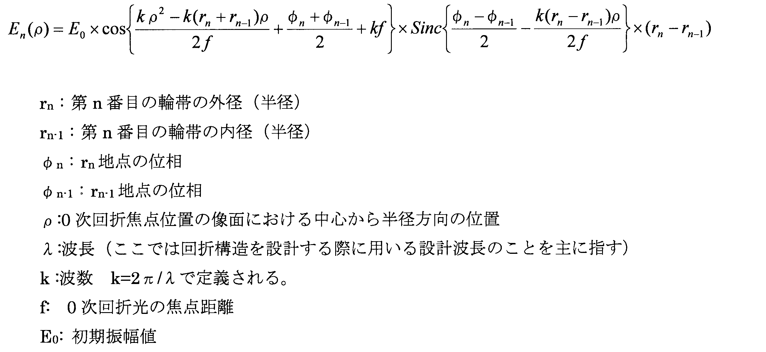
以降の振幅関数の説明に際しては、特に断らない限り、数16を用いることとする。数16の振舞いを各関数に分割して見たものを図6に示す。図6(a)は数16のcos関数の振舞い、また図6(b)は数16のSinc関数の振舞い、さらに図6(c)は数16全体の振舞い、を示す。ここから、回折光が分布する焦点像面上での振幅分布に関して、Sinc関数は振幅分布の包絡線であることが分かる。つまり、Sinc関数が大局的な分布を支配して表す一方、cos関数が細部の微小変化である振る舞いを支配して表すものと考えられる。つまり、振幅分布の全体的な大きさはSinc関数が支配するのである。そして、ハロの成因となる光の強度分布はかかる振幅分布を表わす関数の共役絶対値であることから、ハロを制御するためには元となる振幅分布から制御する必要があり、結局のところ、Sinc関数の振舞いを制御することが重要なのである。Sinc関数とは、Sinc(x)=Sin(x)/x、で定義される関数で、振動しながら減衰する現象を表すのによく用いられる。以下、このSinc関数の振舞いに着目して話を進めていくことにする。
In the following description of the amplitude function, Equation 16 will be used unless otherwise specified. The behavior of Equation 16 divided into functions is shown in FIG. FIG. 6 (a) shows the behavior of the cos function of Eq. 16, FIG. 6 (b) shows the behavior of the Sinc function of Eq. 16, and FIG. 6 (c) shows the behavior of the whole Eq. From this, it can be seen that the Sinc function is an envelope of the amplitude distribution regarding the amplitude distribution on the focal image plane in which the diffracted light is distributed. That is, it is considered that the Sinc function dominates and represents the global distribution, while the cos function dominates and represents the behavior which is a minute change of detail. That is, the overall magnitude of the amplitude distribution is dominated by the Sinc function. And since the light intensity distribution that is the source of halo is the conjugate absolute value of the function that represents such amplitude distribution, in order to control halo, it is necessary to control from the original amplitude distribution, and after all, It is important to control the behavior of the Sinc function. The Sinc function is a function defined by Sinc (x) = Sin (x) / x, and is often used to represent the phenomenon of damping while oscillating. The following discussion will focus on the behavior of the Sinc function.
数16はある輪帯からの光を表した式であり、全体としては全ての輪帯からの光を合算する必要がある。図6(d)に全ての輪帯からの光の振幅関数のグラフを載せたが、分かり難い。そこで、Sinc関数だけに着目すると共に、各輪帯のSinc関数の最大値を規格化して分かり易くしたものを、図7に示す。なお、この図は、図4bに示す比較例のSinc関数を表したものであり、像面中心から外側に向けて第1輪帯から第12輪帯までの各Sinc関数が順次プロットされている。
The equation 16 represents the light from a certain ring zone, and it is necessary to add the lights from all the ring zones as a whole. Although the graph of the amplitude function of the light from all the ring zones is put on FIG.6 (d), it is hard to understand. Therefore, while focusing on only the Sinc function, the maximum value of the Sinc function of each ring zone is normalized to make it easy to understand, which is shown in FIG. In addition, this figure represents the Sinc function of the comparative example shown to FIG. 4 b, and each Sinc function from the 1st ring zone to the 12th ring zone is plotted sequentially toward the outer side from the image surface center .
また、図4aに示す本発明の第一の実施形態のSinc関数を表したものを図8に示す。図7の比較例と比較してみると、Sinc関数の広がり(図の横軸方向への広がり)が大幅に低減していることが分かる。ハロの大幅な低減が期待できることが分かる。より詳細には、図8に示す本実施形態のSinc関数においては、矢印に示すように、各輪帯のSinc関数の頂点の位置が等しくされている。これにより、Sinc関数の広がりが抑えられているのである。
Further, FIG. 8 shows a Sinc function of the first embodiment of the present invention shown in FIG. 4a. As compared with the comparative example of FIG. 7, it can be seen that the spread of the Sinc function (spread in the horizontal axis direction of the drawing) is significantly reduced. It can be seen that a significant reduction of halo can be expected. More specifically, in the Sinc function of the present embodiment shown in FIG. 8, as shown by the arrows, the positions of the vertices of the Sinc function of each ring zone are made equal. This suppresses the spread of the Sinc function.
次に、なぜ第一の実施形態では比較例よりもSinc関数の広がりが低減されるかを、各輪帯のSinc関数の頂点の位置が等しくするための条件を算出することによって説明する。Sinc関数(Sinc(x))における頂点の位置は、x=0となるポイントである。数16のSinc関数の括弧内の関数=0とおいて、第n輪帯の頂点の位置ρnを算出した結果を数17に示す。比較例の位相定数hが一定のフレネル間隔では、数17の(φn-φn-1)/2が一定となる。一方、フレネル間隔では、外側の輪帯ほど(rn-rn-1)が小さくなるのでその分ρnも大きくなる。つまり外側の輪帯ほどSinc関数の頂点の位置が像面の外側へとシフトすることになるのである。これが図7で示される比較例である通常フレネル間隔型におけるSinc関数の頂点の位置がシフトし、全体的にSinc関数が広がることの理由である。
Next, the reason why the spread of the Sinc function is reduced compared to the comparative example in the first embodiment will be described by calculating the condition for making the positions of the vertices of the Sinc function of each ring zone equal. The position of the vertex in the Sinc function (Sinc (x)) is a point where x = 0. The result of calculating the position n n of the vertex of the n-th ring zone is shown in Formula 17 with the function = 0 in the parentheses of the Sinc function of Eq. In the Fresnel interval in which the phase constant h of the comparative example is constant, (φ n −φ n-1 ) / 2 of Expression 17 becomes constant. On the other hand, the Fresnel distance, that amount [rho n becomes large so as the outer annular zone (r n -r n-1) becomes smaller. In other words, the position of the apex of the Sinc function shifts to the outside of the image plane as the outer ring zone is moved. This is the reason why the position of the top of the Sinc function in the normal Fresnel interval type, which is a comparative example shown in FIG. 7, shifts and the Sinc function spreads as a whole.

各輪帯のSinc関数の頂点の位置を等しくするための条件は、第n輪帯の頂点の位置ρnが全て等しいことである。このことを数式化すると、数17を用いて、数18のように表される。そして数18を解くことにより、全ての輪帯の頂点の位置が等しくなるための条件式である数19が得られる。フレネル間隔においては外側の輪帯ほど間隔が狭くなるが、その分、(φn-φn-1)も小さくなるように設定することによって頂点位置が一致し、その地点でSinc関数は固定されるため、比較例のようなSinc関数のシフトは起こらないのである。つまり、かかる条件ではSinc関数の広がりが抑えられることになるのである。
The conditions for equalizing the positions of the vertices of the Sinc function of each zone are that the positions ρ n of the vertices of the n-th zone are all equal. This can be expressed as Equation 18 using Equation 17. By solving Equation 18, Equation 19 which is a conditional expression for equalizing the positions of the vertexes of all the ring zones is obtained. In the Fresnel interval, the interval becomes narrower as the outer ring zone gets smaller, but by setting (φ n -φ n-1 ) to be smaller accordingly, the vertex positions coincide and the Sinc function is fixed at that point Therefore, the shift of the Sinc function as in the comparative example does not occur. That is, under such conditions, the spread of the Sinc function can be suppressed.


次に具体的な数値を用いてかかるSinc関数の制御の例を述べる。数19を用いて、本発明の第一の実施形態として、全ての輪帯が、Sinc関数の頂点位置においてρ=0.1055mmで一致するように、ブレーズ21のφn、φn-1を計算した結果を示したのが表1である。なお、rn、rn-1については、表2に示す比較例と同じである。
Next, an example of control of such a Sinc function will be described using specific numerical values. Using Eq. 19, according to the first embodiment of the present invention, φ n and φ n-1 of the blaze 21 are set so that all the annular zones coincide at 頂点 = 0.1055 mm at the vertex position of the Sinc function. Table 1 shows the calculated results. The r n and r n-1 are the same as in the comparative example shown in Table 2.
図9(a)に、本実施形態の0次回折光の焦点像面における強度分布について、計算機上でシミュレートした結果を、比較例(b)と比較して示す。この図は、ハロが問題となる夜間を想定して開口径=5.12mmで計算したものである。なお、以降の各実施形態及び比較例の像面及び光軸上の強度分布の計算に際して、ブレーズ構造が存在しない領域は設定屈折力に基づく屈折領域のみが存在するとして計算した。また、0次回折光の焦点像面の強度分布は、特に断りがない限り、本実施形態と同じ開口径=5.12mmで計算したもので示すこととする。この図から明らかなように、(a)に示す本実施形態では、(b)に示す比較例に比べて、大幅にサイドバンドの強度が低下していることが分かる。
FIG. 9A shows the result of simulating on a computer the intensity distribution on the focal image plane of the zeroth-order diffracted light of the present embodiment in comparison with the comparative example (b). This figure is calculated with an aperture diameter of 5.12 mm assuming nighttime when halo is a problem. In the calculation of the intensity distribution on the image plane and the optical axis in each of the following embodiments and comparative examples, it is calculated that only the refractive area based on the set refractive power is present in the area where the blaze structure does not exist. Further, the intensity distribution of the focal image plane of the zeroth-order diffracted light is calculated by the same aperture diameter = 5.12 mm as in this embodiment unless otherwise noted. As apparent from this figure, it can be seen that in the present embodiment shown in (a), the strength of the sideband is significantly reduced as compared with the comparative example shown in (b).
次に、図10に、本実施形態の夜間時の遠方光源の実写写真を、比較例と対比して示す。今回試作したコンタクトレンズは2-ヒドロキシエチルメタクリレートを主成分とする含水率約37.5%の含水性ソフトコンタクトレンズで、レンズ径=14mm、光学部径=8mm、光学部後面16のベースカーブ=8.5mm、のものである。また、この図は、回折型レンズにおける公知の課題であるハロが問題となる夜間の瞳孔径が広がった状態を想定して開放絞りで撮影したものである。以下、実写写真撮影用のコンタクトレンズの試作品の条件や写真の撮影条件は、今回と同じであるので、省略する。すなわち実測結果からも、図10(a)に示す本実施形態では、図10(b)に示す比較例と比較して、ハロが明らかに低減出来ていることが分かった。
Next, FIG. 10 shows a photographed image of a distant light source at night time of the present embodiment in comparison with a comparative example. The contact lens manufactured this time is a water-containing soft contact lens with a moisture content of about 37.5% mainly composed of 2-hydroxyethyl methacrylate, lens diameter = 14 mm, optical part diameter = 8 mm, base curve of optical part rear surface 16 = It is 8.5 mm. Further, this figure is taken with an open stop on the assumption that the pupil diameter at night, which is a problem of halo which is a known problem in a diffractive lens, becomes large. Hereinafter, the conditions of the trial product of the contact lens for photographing and the photographing conditions of the photograph are the same as the present embodiment, and therefore, the description thereof is omitted. That is, also from the actual measurement results, it was found that the halo was clearly reduced in the present embodiment shown in FIG. 10 (a) as compared with the comparative example shown in FIG. 10 (b).
図11に、図4aに示す本実施形態に従うブレーズ形状によって得られる光軸上の強度分布について、計算機上でシミュレートした結果を示す。図11は、光の入射する開口径を変えた時の光軸上の強度分布の変化を見たものである。本発明の眼用レンズがコンタクトレンズや眼内レンズのように眼の瞳孔近くで用いられる場合、瞳孔径とほぼ同じ大きさのレンズの領域を光の入射する有効開口径とみなすことができることから、(a)(開口径=2.0mm)は晴天の昼間の屋外、(b)(開口径=3.3mm)は明るい室内、(c)(開口径=4.2mm)は薄暗い室内、の環境下に相当する強度分布をそれぞれ示していると考えられる。また、図11(d)は、開口径3.3mmでの比較例の光軸上の強度分布を示している。このように、開口径が小、中、大と変化しても近方と遠方の両領域に焦点が生成する、すなわち多焦点眼用レンズとして機能しうるものであることが分かる。また、本実施形態では開口径が大きくなるにしたがい遠方の強度が増す結果となっているが、この特性は、暗くなった時(瞳孔径が拡大している時)の近方の見え方はさほど重要ではなく、遠方の見え方の方が重視されるという現実的な要求に合致したものであると言える。
FIG. 11 shows a computer simulation result of the intensity distribution on the optical axis obtained by the blazed shape according to the present embodiment shown in FIG. 4a. FIG. 11 shows the change of the intensity distribution on the optical axis when the diameter of the opening through which light is incident is changed. When the ophthalmic lens of the present invention is used near the pupil of the eye, such as a contact lens or an intraocular lens, the area of the lens having approximately the same size as the pupil diameter can be regarded as the effective aperture diameter at which light is incident. , (A) (aperture diameter = 2.0 mm) in sunny daytime outdoors, (b) (aperture diameter = 3.3 mm) in a bright room, (c) (aperture diameter = 4.2 mm) in a dim indoor room, It is considered that the respective intensity distributions corresponding to the environment are shown. Further, FIG. 11D shows the intensity distribution on the optical axis of the comparative example at an aperture diameter of 3.3 mm. Thus, it can be understood that even if the aperture diameter changes from small to middle to large, the focal point is generated in both the near and far regions, that is, it can function as a multifocal ophthalmic lens. Further, in the present embodiment, the distance strength increases as the aperture diameter becomes larger, but this characteristic is the appearance of nearness when it gets dark (when the pupil diameter is enlarged). It does not matter so much, and it can be said that it meets the practical requirement that the way of looking at distant places is emphasized.
さらには、比較例の光軸上の強度分布との対比から、最も使用頻度の高い明るい室内の環境下において、比較例(図11(d))とほぼ同じ遠近の強度パターン(図11(b))を示していることから、本実施形態で示した前記ハロの低減効果は、標準的なフレネル間隔型と同等の遠近の見え方を維持しつつ、成し遂げられたものであることが分かるのである。なお、以降の実施形態の比較例は、第一の実施形態と同じ観点に基づき設定されている。つまり、構成輪帯数が各実施形態と同じで、かつ明るい室内を想定した環境下(具体的には開口径(直径)3.3mm)の光軸上の強度分布のパターンが各実施形態とほぼ等しくなるように一定の位相定数が設定された標準的なフレネル間隔のものを比較例とした。
Furthermore, from the comparison with the intensity distribution on the optical axis of the comparative example, in the bright room environment with the highest frequency of use, the near-far intensity pattern (FIG. 11 (b) substantially the same as the comparative example (FIG. 11 (d)) Since it shows that the reduction effect of the halo described in the present embodiment is achieved while maintaining the same perspective as the standard Fresnel distance type, it is understood from the above). is there. In addition, the comparative example of subsequent embodiment is set based on the same viewpoint as 1st embodiment. That is, the pattern of the intensity distribution on the optical axis under the same environment as that of each embodiment and assuming a bright room (specifically, the aperture diameter (diameter) of 3.3 mm) is the same as in each embodiment. A comparative example is a standard Fresnel interval in which a constant phase constant is set to be approximately equal.
以上、本発明の一実施形態について詳述してきたが、これはあくまでも例示であって、本発明は、かかる実施形態における具体的な記載によって、何等、限定的に解釈されるものではない。以下に、本発明において好適に採用され得るその他の態様を幾つか示すが、本発明が以下の態様に限定されることを示すものではないことが理解されるべきである。なお、以下の説明において、前述の実施形態と実質的に同様の部材および部位については、前述の実施形態と同様の符号を付することによって、詳細な説明を省略する。
As mentioned above, although one embodiment of the present invention has been described in detail, this is merely an example, and the present invention is not to be construed as being limited at all by the specific description in the embodiment. Although some other embodiments that can be suitably adopted in the present invention are shown below, it should be understood that the present invention is not limited to the following embodiments. In the following description, components and portions substantially similar to those of the above-described embodiment are denoted by the same reference numerals as those of the above-described embodiment, and the detailed description thereof will be omitted.
図12(a)に、本発明の第二の実施形態としての位相プロファイル30を示す。本実施形態では、第一の実施形態と同様、5つの輪帯からなる回折構造20の格子ピッチが同じフレネル間隔で形成されている。一方、表3に示すように、ブレーズ高さに相当する位相φn、φn-1が異なっている。また、比較例の位相プロファイル32を図12(b)に示す。本比較例は、表4に示すように本実施形態と同じく輪帯数が5で構成され、かつ明るい室内での光軸上の強度パターンが本実施形態とほぼ同じになるように位相定数h=0.4一定としたものである。
FIG. 12 (a) shows a phase profile 30 according to a second embodiment of the present invention. In the present embodiment, as in the first embodiment, the grating pitch of the diffractive structure 20 consisting of five orbicular zones is formed with the same Fresnel distance. On the other hand, as shown in Table 3, the phases φ n and φ n-1 corresponding to the blaze height are different. Moreover, the phase profile 32 of a comparative example is shown in FIG.12 (b). As shown in Table 4, in this comparative example, the number of ring zones is five as in this embodiment, and the phase constant h on the optical axis in a bright room is almost the same as that of this embodiment. = 0.4 is constant.

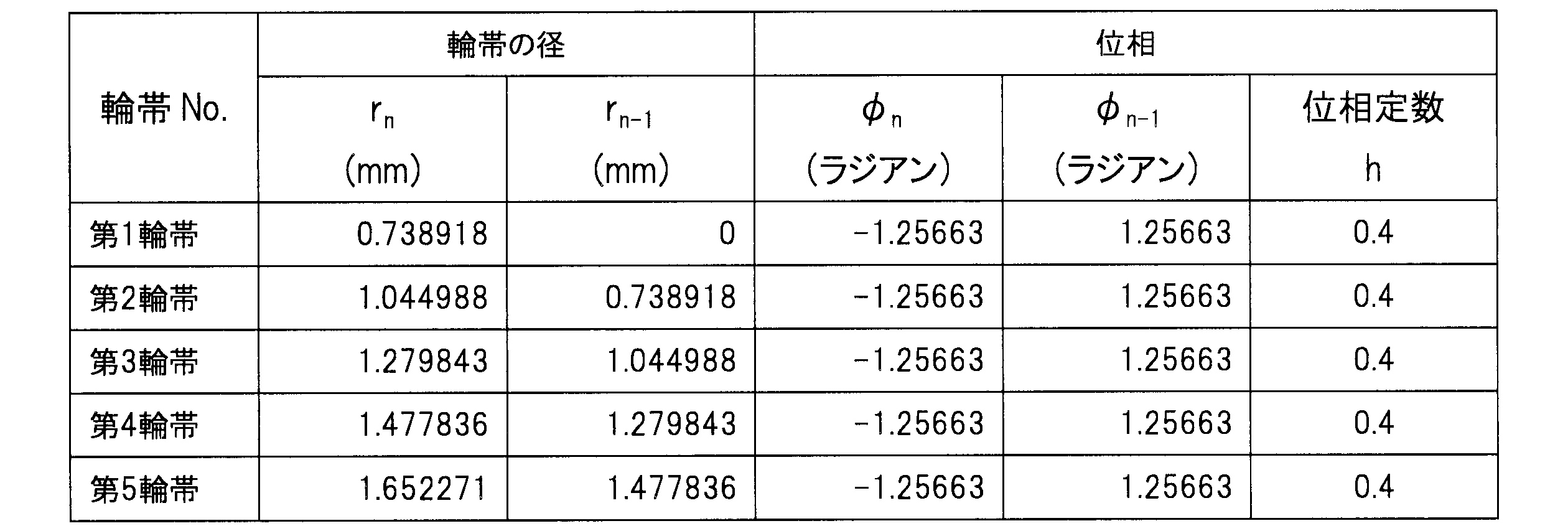
本実施形態の特徴を明確にするために、本実施形態のSinc関数の計算結果を図13に示す。この図から分かるように、本実施形態の特徴は第一輪帯を除いた各輪帯のSinc関数の値が0になる位置(節)(図中矢印)を等しくしたことである。これにより、図7に示す比較例の第1~第5輪帯までに相当するSinc関数の広がりと比較して明らかなように、Sinc関数の広がりが大幅に低減しており、ハロの大幅な低減が期待できるのである。このようにSinc関数の節で一致することによって各輪帯のSinc関数の最大振幅は節の位置で収束するようにして分布することとなり、全体としてのSinc関数の広がりが抑制されることは容易に理解できる。
In order to clarify the feature of the present embodiment, the calculation result of the Sinc function of the present embodiment is shown in FIG. As can be seen from this figure, the feature of this embodiment is that the positions (nodes) (arrows in the figure) at which the value of the Sinc function of each ring zone excluding the first ring zone is 0 are equal. Thereby, as apparent from comparison with the spread of the Sinc function corresponding to the first to fifth annular zones in the comparative example shown in FIG. 7, the spread of the Sinc function is significantly reduced, and the halo is significantly reduced. A reduction can be expected. As described above, by matching at the nodes of the Sinc function, the maximum amplitudes of the Sinc functions of the respective zones are distributed so as to converge at the node position, and it is easy to suppress the spread of the Sinc function as a whole Understand.
次に、本実施形態を基にして各輪帯のSinc関数の値が0になる位置(節)を等しくするための条件を算出することにする。Sinc関数(Sinc(x))の値が0になる位置(節)は、x=βπとなるポイントである。数16のSinc関数の括弧内の関数=βπ(βはゼロを除く整数)とおいて、第n輪帯のSinc関数の値が0になる位置(節)ρnを算出した結果を数20に示す。数20を用いて各輪帯のSinc関数の値が0になる位置(節)を等しくするための条件を算出すると、数21が得られる。
Next, based on the present embodiment, conditions for equalizing the positions (nodes) where the value of the Sinc function of each ring zone becomes 0 are calculated. The position (node) where the value of the Sinc function (Sinc (x)) is 0 is a point where x = βπ. The result of calculating the position (node) n n where the value of the Sinc function of the n-th ring becomes 0 with the function = βπ (β is an integer excluding zero) in parentheses of the Sinc function of Eq. Show. If the condition for equalizing the position (node) where the value of the Sinc function of each ring zone becomes 0 is calculated using Expression 20, Expression 21 is obtained.


なお、節は無数に存在するので、各輪帯間のSinc関数が、同一の節で一致してもよいし、あるいは異なる節で一致してもよい。たとえば二つの輪帯(j=m、j=n)において異なる節位置で一致する場合も含む条件は数3のように表される。なお、本実施形態は、第2~5輪帯までのSinc関数の節(β=1)をρ=0.45mmで一致させた例となっている。
Since there are innumerable clauses, Sinc functions between the respective ring zones may be identical in the same clause or may be identical in different clauses. For example, the condition including the case of matching at different node positions in two ring zones (j = m, j = n) is expressed as Equation 3. The present embodiment is an example in which the nodes (β = 1) of the Sinc function in the second to fifth ring zones are matched at = 0. = 0.45 mm.
図14に、本実施形態(a)と比較例(b)の0次回折光の焦点像面における強度分布について、計算機上でシミュレートした結果を示す。比較例と比べることにより、本実施形態においてサイドバンドの生成範囲が狭まっていることが分かる。
FIG. 14 shows the result of simulation on a computer about the intensity distribution in the focal image plane of the zeroth-order diffracted light in the present embodiment (a) and the comparative example (b). By comparing with the comparative example, it can be seen that the generation range of the side band is narrowed in the present embodiment.
次に、図15に、本実施形態の遠方光源の実写写真を示す。すなわち実測結果からも、ハロが明らかに小さくなっており、軽減出来ていることが明らかとなった。
Next, FIG. 15 shows a photographed image of the far-field light source of this embodiment. That is, also from the measurement results, it has become clear that halo is clearly reduced and reduced.
図16に、図12(a)に示す本実施形態に従うブレーズ形状によって得られる光軸上の強度分布について、計算機上でシミュレートした結果を示す。なお、比較例の光軸上の強度分布(d)も併せて示した。図16は、図11と同様に、光の入射する開口径を変えた時の光軸上の強度分布の変化を見たもので、開口径が小、中、大と変化しても近方と遠方の両領域に焦点が生成する、すなわち多焦点眼用レンズとして機能しうるものであることが分かる。また、比較例の光軸上の強度分布との対比から、明るい室内の環境下において、標準的なフレネル間隔型のもの(図16(d))とほぼ同じ遠近の強度パターン(図16(b))を示していることから、本実施形態の回折レンズでは標準的なフレネル間隔型と同等の遠近の見え方を与えつつ、ハロ低減に効果をもたらすものであることも分かるのである。
FIG. 16 shows the result of computer simulation of the intensity distribution on the optical axis obtained by the blazed shape according to the present embodiment shown in FIG. 12 (a). The intensity distribution (d) on the optical axis of the comparative example is also shown. Similar to FIG. 11, FIG. 16 shows the change in the intensity distribution on the optical axis when the aperture diameter at which light is incident is changed. Even if the aperture diameter is small, medium, large, it is close It can be seen that the focal point is generated in both the far and far areas, that is, it can function as a multifocal ophthalmic lens. In addition, from the contrast with the intensity distribution on the optical axis of the comparative example, in the bright room environment, the intensity pattern (see FIG. 16 (b)) which is almost the same as the standard Fresnel interval type (FIG. 16 (d)). It is also apparent from the fact that the diffractive lens of the present embodiment is effective in reducing halo while giving the same perspective as the standard Fresnel distance type.
図17(a)に、本発明の第三の実施形態としての位相プロファイル34の拡大断面図を示す。本実施形態では、表5に示すように5つの輪帯からなる回折構造20の格子ピッチが第一の実施形態と同じフレネル間隔で構成されたものである。なお、位相φn、φn-1は表5に示すように設定されている。一方、図17(b)に比較例の位相プロファイル36を示す。本比較例は表6に示すように、本実施形態と同じ5つの輪帯数で構成されたものであり、明るい室内での光軸上の強度パターンが本実施形態とほぼ同じになるように位相定数h=0.5一定としたものである。
FIG. 17 (a) shows an enlarged cross-sectional view of a phase profile 34 as a third embodiment of the present invention. In the present embodiment, as shown in Table 5, the grating pitch of the diffractive structure 20 consisting of five orbicular zones is configured with the same Fresnel distance as in the first embodiment. The phases φ n and φ n-1 are set as shown in Table 5. On the other hand, FIG. 17 (b) shows a phase profile 36 of the comparative example. As shown in Table 6, this comparative example is composed of the same five ring numbers as this embodiment, and the intensity pattern on the optical axis in a bright room is almost the same as this embodiment. The phase constant h = 0.5 is constant.


本実施形態の特徴を明確にするために、本実施形態のSinc関数の計算結果を図18(a)に示す。また、図18(b)に比較例の各輪帯のSinc関数を示す。図18(b)の比較例においては、像面中心から外側に向けて第1輪帯から第8輪帯までの各Sinc関数が順次プロットされている。図18から分かるように、本実施形態の特徴は、各輪帯のSinc関数が極値を示す位置を等しくしたことである。これにより、図18(b)に示す比較例(第1~5輪帯までに相当するSinc関数の広がり)と比較して明らかなように、Sinc関数の広がりが抑制されていることがわかる。Sinc関数の極値を一致させることによって第二の実施形態と同様にSinc関数が極値に向って急激に収束するため、Sinc関数の広がりが抑制されたものとなっている。よって、かかる例においても他の実施形態と同様にSinc関数の広がりの低減すなわちハロの低減が期待できるのである。
In order to clarify the feature of the present embodiment, the calculation result of the Sinc function of the present embodiment is shown in FIG. Further, FIG. 18B shows a Sinc function of each ring zone of the comparative example. In the comparative example of FIG. 18B, the Sinc functions from the first to eighth ring zones are plotted in order from the image plane center to the outside. As can be seen from FIG. 18, the feature of the present embodiment is that the Sinc functions of the respective ring zones have equal positions at which extrema are shown. From this, it is understood that the spread of the Sinc function is suppressed, as is clear as compared with the comparative example (the spread of the Sinc function corresponding to the first to fifth ring zones) shown in FIG. 18 (b). Since the Sinc function converges rapidly toward the extreme value as in the second embodiment by matching the extreme value of the Sinc function, the spread of the Sinc function is suppressed. Therefore, in this example as well, as in the other embodiments, reduction of the spread of the Sinc function, that is, reduction of the halo can be expected.
次に、各輪帯のSinc関数が極値を示す位置を等しくするための条件を算出することにする。Sinc関数(Sinc(x))の値が極値を示す位置は、x=σαとなるポイントである。σαの詳細については、表7に示す。なお、αが奇数の時、極値は極小値となり、αが偶数の時、極値は極大値となる。数16のSinc関数の括弧内の関数=σαとおいて、第n輪帯の値が極値を示す位置ρnを算出し、各輪帯のSinc関数の値が極値を示す位置を等しくするための条件を求めると、数22のようにあらわされる。
Next, conditions for equalizing the positions where the Sinc functions of the respective ring bands show extreme values are calculated. The position where the value of the Sinc function (Sinc (x)) indicates the extremum is a point where x = σ α . The details of σ α are shown in Table 7. When α is an odd number, the extremum is a local minimum, and when α is an even number, the extrema is a local maximum. The position n n at which the value of the n-th ring indicates the extremum is calculated with the function = σ α in the parentheses of the Sinc function of Eq. 16 and the positions of the Sinc functions at the individual ring zones indicate the extremum If the condition for doing is calculated | required, it will be represented like several 22.


なお、Sinc関数の極値を示す位置も無数(xの増大とともにSinc(x)はゼロに漸近するので実用上は有限の数が対象となる)に存在するので、各輪帯間のSinc関数が、同一の極値を示す位置で合致してもよいし、あるいは輪帯間で異なる極値を示す位置で一致してもよい。異なる極値を示す位置で一致させる場合は、異なるσαを代入して計算すればよい。たとえば二つの輪帯(j=m、j=n)において異なる極値σs、σtを示す位置で一致する場合も含む条件は数4のように表される。なお、本実施形態は、各輪帯のSinc関数が、第一輪帯ではα=5、第二輪帯ではα=2、そして第3~5輪帯ではα=1の極値σαにてρ=0.7mmの位置で一致するようにしたものである。
In addition, since the position indicating the extreme value of the Sinc function also exists in an infinite number (since Sinc (x) asymptotically approaches zero as the x increases, a finite number is practically used), the Sinc function between the respective ring zones However, they may coincide at positions indicating the same extreme value, or may coincide at positions indicating different extreme values between the ring zones. When matching at positions indicating different extreme values, calculation may be performed by substituting different σ α . For example, the condition including the case of coincidence at the positions indicating different extreme values σ s and σ t in two ring zones (j = m, j = n) is expressed as Expression 4. In this embodiment, the Sinc function of each ring zone is set to an extreme value σ α of α = 5 for the first ring zone, α = 2 for the second ring zone, and α = 1 for the third to fifth ring zones. Therefore, they coincide with each other at a position of ρ = 0.7 mm.
図19(a)に本実施形態の0次回折光の焦点像面の強度分布について計算機上でシミュレートした結果を、図19 (b) に比較例の計算結果を、それぞれ示す。(b)に示す比較例と比べることにより、本実施形態において明らかにサイドバンドの強度が低減されていることが分かる。
FIG. 19 (a) shows the result of simulating on a computer the intensity distribution of the focal image plane of 0th order diffracted light of this embodiment, and FIG. 19 (b) shows the calculation result of the comparative example. By comparing with the comparative example shown in (b), it can be seen that the intensity of the sideband is clearly reduced in the present embodiment.
図20に、図17(a)に示す本実施形態に従うブレーズ形状によって得られる光軸上の強度分布について、計算機上でシミュレートした結果を示す。また、比較例の光軸上の強度分布を図20(d)に示す。図20は、光の入射する開口径を変えた時の光軸上の強度分布の変化を見たもので、開口径が小、中、大と変化しても近方と遠方の両領域に焦点が生成する、すなわち多焦点眼用レンズとして機能しうるものであることが分かる。また、比較例の光軸上の強度分布との対比から、明るい室内の環境下において、標準的なフレネル間隔型のもの(図20(d))とほぼ同じ遠近の強度パターン(図20(b))を示していることから、本実施形態の回折レンズでは標準的なフレネル間隔型と同等の遠近の見え方を与えつつ、ハロ低減に効果をもたらすものであることも分かるのである。
FIG. 20 shows the result of computer simulation of the intensity distribution on the optical axis obtained by the blazed shape according to the present embodiment shown in FIG. 17A. The intensity distribution on the optical axis of the comparative example is shown in FIG. FIG. 20 shows the change in the intensity distribution on the optical axis when the aperture diameter at which light is incident is changed, and the aperture diameter is small, medium and large, both in the near and far regions. It can be seen that the focus is generated, ie it can function as a multifocal ophthalmic lens. In addition, from the contrast with the intensity distribution on the optical axis of the comparative example, in the bright room environment, the intensity pattern (see FIG. 20 (b)) which is almost the same as the standard Fresnel interval type (FIG. 20 (d)). It is also apparent from the fact that the diffractive lens of the present embodiment is effective in reducing halo while giving the same perspective as the standard Fresnel distance type.
図21(a)に、本発明の第四の実施形態の位相プロファイル38を示す。表8に示すように9つの輪帯からなる回折構造20の格子ピッチが第一の実施形態と同じフレネル間隔で構成されたものである。なお、位相φn、φn-1は表8に示すように設定されている。一方、図21(b)に比較例の位相プロファイル40を示す。本比較例は表9に示すように、本実施形態と同じ9つの輪帯数がフレネル間隔で構成されたものであり、明るい室内での光軸上の強度パターンが本実施形態とほぼ同じになるように位相定数h=0.4一定としたものである。
FIG. 21 (a) shows a phase profile 38 of the fourth embodiment of the present invention. As shown in Table 8, the grating pitch of the diffractive structure 20 consisting of nine orbicular zones is configured with the same Fresnel distance as in the first embodiment. The phases φ n and φ n-1 are set as shown in Table 8. On the other hand, FIG. 21 (b) shows a phase profile 40 of the comparative example. In this comparative example, as shown in Table 9, the same nine ring numbers as in this embodiment are formed by Fresnel intervals, and the intensity pattern on the optical axis in a bright room is almost the same as in this embodiment. Thus, the phase constant h = 0.4 is constant.


本実施形態の特徴を明確にするために、本実施形態のSinc関数の計算結果を図22に示す。この図から分かるように、本実施形態の特徴は、第2~4輪帯の頂点をρ=0.127mm(図中矢印A)で等しくすると共に、第5~9輪帯のSinc関数が0となる位置(節)(β=1)をρ=0.637mm(図中矢印B)で等しくしたことである。この場合でも、図7に示す比較例(第1~9輪帯までに相当するSinc関数の広がり)と比較して明らかなように、Sinc関数の広がりが抑制されていることがわかる。よって、他の実施形態と同様にSinc関数の広がりの低減すなわちハロの低減が期待できる。
In order to clarify the feature of this embodiment, the calculation result of the Sinc function of this embodiment is shown in FIG. As can be seen from this figure, the feature of this embodiment is that the apexes of the second to fourth ring zones are made equal by ρ = 0.127 mm (arrow A in the figure) and the Sinc function of the fifth to ninth ring zones is 0. The position (node) (β = 1) at which is equal to ρ = 0.637 mm (arrow B in the figure). Also in this case, it is understood that the spread of the Sinc function is suppressed, as apparent from comparison with the comparative example shown in FIG. 7 (the spread of the Sinc function corresponding to the first to ninth ring zones). Therefore, as in the other embodiments, the reduction of the spread of the Sinc function, that is, the reduction of the halo can be expected.
図23(a)に本実施形態の、図23(b)に比較例の0次回折光の焦点像面の強度分布について、計算機上でシミュレートした結果をそれぞれ示す。(b)に示す比較例と比べることにより、本実施形態において像面外周領域(ρ=0.45~0.6辺り)のサイドバンドの強度が明らかに低減出来ていることが分かる。
FIG. 23A shows the results of simulation on a computer about the intensity distribution of the focal image plane of the zeroth-order diffracted light of the comparative example of the present embodiment and FIG. As compared with the comparative example shown in (b), it can be seen that the intensity of the side band in the outer peripheral region (領域 = 0.45 to 0.6) in the present embodiment is clearly reduced in the present embodiment.
図24に、図21(a)に示す本実施形態に従うブレーズ形状によって得られる光軸上の強度分布について、計算機上でシミュレートした結果を示す。図24は、光の入射する開口径を変えた時の光軸上の強度分布の変化を見たもので、開口径が小、中、大と変化しても近方と遠方の両領域に焦点が生成する、すなわち多焦点眼用レンズとして機能しうるものであることが分かる。また、明るい室内における光軸上の強度パターン(図24(b))は比較例(図11(d))とほぼ同じであることから、本実施形態の回折レンズでは標準的なフレネル間隔型と同等の遠近の見え方を与えつつ、ハロ低減に効果をもたらすものであることも分かるのである。
FIG. 24 shows the result of computer simulation of the intensity distribution on the optical axis obtained by the blazed shape according to the present embodiment shown in FIG. 21 (a). FIG. 24 shows the change in the intensity distribution on the optical axis when the aperture diameter at which light is incident is changed, and the aperture diameter is small, medium, large, even in the near and far regions. It can be seen that the focus is generated, ie it can function as a multifocal ophthalmic lens. Further, since the intensity pattern on the optical axis in the bright room (FIG. 24 (b)) is almost the same as the comparative example (FIG. 11 (d)), the diffractive lens of this embodiment It is also understood that it is effective for halo reduction while giving an equivalent perspective view.
図25(a)に、本発明の第五の実施形態の位相プロファイル42を示す。本実施形態は、表10に示すように7つの輪帯からなる回折構造20の格子ピッチが第一の実施形態と同じフレネル間隔で構成されたものである。なお、位相φn、φn-1は表10に示すように設定されている。一方、図25(b)に比較例の位相プロファイル44を示す。本比較例は表11に示すように、本実施形態と同じ7つの輪帯数がフレネル間隔で構成されたものであり、明るい室内での光軸上の強度パターンが本実施形態とほぼ同じになるように位相定数h=0.5一定としたものである。
FIG. 25 (a) shows a phase profile 42 of the fifth embodiment of the present invention. In the present embodiment, as shown in Table 10, the grating pitch of the diffractive structure 20 consisting of seven orbicular zones is configured with the same Fresnel distance as in the first embodiment. The phases φ n and φ n-1 are set as shown in Table 10. On the other hand, FIG. 25 (b) shows a phase profile 44 of the comparative example. In this comparative example, as shown in Table 11, the same seven ring numbers as in this embodiment are formed by Fresnel intervals, and the intensity pattern on the optical axis in a bright room is almost the same as in this embodiment. Thus, the phase constant h = 0.5 is constant.


本実施形態の特徴を明確にするために、本実施形態のSinc関数の計算結果を図26に示す。この図および表10から分かるように、本実施形態の特徴は、第1~3輪帯のSinc関数の頂点をρ=0.1055mm(図中矢印A)で等しくすると共に、第4~7輪帯のSinc関数の極値となる位置(α=1)をρ=0.8mm(図中矢印B)で等しくしたことである。この場合でも、図18(b)に示す比較例(第1~7輪帯までに相当するSinc関数の広がり)と比較して明らかなように、Sinc関数の広がりが抑制されていることがわかる。よって、他の実施形態と同様にSinc関数の広がりの低減すなわちハロの低減が期待できる。
In order to clarify the feature of this embodiment, the calculation result of the Sinc function of this embodiment is shown in FIG. As can be seen from this figure and Table 10, the feature of this embodiment is that the apexes of the Sinc functions of the first to third zones are equal at ρ = 0.1055 mm (arrow A in the figure), and The positions (α = 1) at the extreme values of the band Sinc function are equal at ρ = 0.8 mm (arrow B in the figure). Also in this case, it is understood that the spread of the Sinc function is suppressed, as is clear as compared with the comparative example (the spread of the Sinc function corresponding to the first to seventh ring zones) shown in FIG. . Therefore, as in the other embodiments, the reduction of the spread of the Sinc function, that is, the reduction of the halo can be expected.
図27(a)に本実施形態の、図27(b)に比較例の0次回折光の焦点像面の強度分布について計算機上でシミュレートした結果をそれぞれ示す。(b)に示す比較例と比べることにより、本実施形態において明らかにサイドバンドの強度が低減出来ていることが分かる。
FIG. 27A shows the result of simulation on a computer about the intensity distribution of the focal image plane of the zeroth-order diffracted light of the comparative example of the present embodiment and FIG. By comparing with the comparative example shown in (b), it can be seen that the intensity of the sideband is clearly reduced in the present embodiment.
図28に、図25(a)に示す本実施形態に従うブレーズ形状によって得られる光軸上の強度分布について、計算機上でシミュレートした結果を示す。図28は、光の入射する開口径を変えた時の光軸上の強度分布の変化を見たもので、開口径が小、中、大と変化しても近方と遠方の両領域に焦点が生成する、すなわち多焦点眼用レンズとして機能しうるものであることが分かる。また、明るい室内における光軸上の強度パターン(図28(b))は比較例(図20(d))とほぼ同じであることから、本実施形態の回折レンズでは標準的なフレネル間隔型と同等の遠近の見え方を与えつつ、ハロ低減に効果をもたらすものであることも分かるのである。
FIG. 28 shows the result of computer simulation of the intensity distribution on the optical axis obtained by the blazed shape according to the present embodiment shown in FIG. 25 (a). FIG. 28 shows the change in the intensity distribution on the optical axis when the aperture diameter into which light is incident is changed, and the aperture diameter is small, medium, large, even in the near and far regions. It can be seen that the focus is generated, ie it can function as a multifocal ophthalmic lens. Further, since the intensity pattern on the optical axis in the bright room (FIG. 28 (b)) is almost the same as the comparative example (FIG. 20 (d)), the diffractive lens of this embodiment It is also understood that it is effective for halo reduction while giving an equivalent perspective view.
図29(a)に、本発明の第六の実施形態の位相プロファイル46を示す。本実施形態は、表12に示すように8つの輪帯からなる回折構造20の格子ピッチが第一の実施形態と同じフレネル間隔で構成されたものである。なお、位相φn、φn-1は表12に示すように設定されている。一方、図29(b)に比較例の位相プロファイル48を示す。本比較例は表13に示すように、本実施形態と同じ8つの輪帯数がフレネル間隔で構成されたものであり、明るい室内での光軸上の強度パターンが本実施形態とほぼ同じになるように位相定数h=0.53一定としたものである。
FIG. 29 (a) shows a phase profile 46 of the sixth embodiment of the present invention. In the present embodiment, as shown in Table 12, the grating pitch of the diffraction structure 20 consisting of eight orbicular zones is configured with the same Fresnel distance as that of the first embodiment. The phases φ n and φ n-1 are set as shown in Table 12. On the other hand, FIG. 29 (b) shows a phase profile 48 of the comparative example. In this comparative example, as shown in Table 13, the same eight ring numbers as in this embodiment are formed by Fresnel intervals, and the intensity pattern on the optical axis in a bright room is almost the same as in this embodiment. Thus, the phase constant h is fixed at 0.53.


本実施形態の特徴を明確にするために、本実施形態のSinc関数の計算結果を図30(a)に示す。この図から分かるように、本実施形態の特徴は、第1輪帯のSinc関数が極値となる位置(α=5)と第2輪帯のSinc関数が極値となる位置(α=2)と第3,4輪帯のSinc関数が極値となる位置(α=1)をρ=0.7mm(図中矢印B)で等しくすると共に、第5~8輪帯のSinc関数が0となる位置(節)(β=1)をρ=0.6mm(図中矢印A)で等しくしたことである。この場合でも、図30(b)に示す比較例(第1~8輪帯までに相当するSinc関数の広がり)と比較して明らかなように、Sinc関数の広がりが抑制されていることがわかる。よって、他の実施形態と同様にSinc関数の広がりの低減すなわちハロの低減が期待できる。
In order to clarify the feature of the present embodiment, the calculation result of the Sinc function of the present embodiment is shown in FIG. As can be seen from this figure, the feature of the present embodiment is the position where the Sinc function of the first ring zone is the extremum (α = 5) and the position where the Sinc function of the second ring zone is the extremum (α = 2) And the third and fourth ring zones have the Sinc function at the extreme value (α = 1) equal at = 0. = 0.7 mm (arrow B in the figure), and the fifth to eighth ring Sinc functions are zero. The position (node) (β = 1) at which is equal at ρ = 0.6 mm (arrow A in the figure). Also in this case, it is understood that the spread of the Sinc function is suppressed, as is clear as compared with the comparative example (the spread of the Sinc function corresponding to the first to eighth ring zones) shown in FIG. . Therefore, as in the other embodiments, the reduction of the spread of the Sinc function, that is, the reduction of the halo can be expected.
図31(a)に本実施形態の、図31(b)に比較例の0次回折光の焦点像面の強度分布について計算機上でシミュレートした結果をそれぞれ示す。(b)に示す比較例と比べることにより、本実施形態においてサイドバンドの強度及び分布の広がりがかなり抑制されていることが分かる。
FIG. 31 (a) shows the results of simulation on a computer about the intensity distribution of the focal image plane of the zero-order diffracted light of the comparative example of this embodiment and FIG. 31 (b) of this embodiment. By comparison with the comparative example shown in (b), it can be seen that the spread of the intensity and distribution of the sidebands is considerably suppressed in the present embodiment.
図32に、図29(a)に示す本実施形態に従うブレーズ形状によって得られる光軸上の強度分布について、計算機上でシミュレートした結果を示す。図32は、光の入射する開口径を変えた時の光軸上の強度分布の変化を見たもので、開口径が小、中、大と変化しても近方と遠方の両領域に焦点が生成する、すなわち多焦点眼用レンズとして機能しうるものであることが分かる。また、明るい室内における光軸上の強度パターン(図32(b))は比較例(図32(d))とほぼ同じであることから、本実施形態の回折レンズでは標準的なフレネル間隔型と同等の遠近の見え方を与えつつ、ハロ低減に効果をもたらすものであることも分かるのである。
FIG. 32 shows a computer simulation result of the intensity distribution on the optical axis obtained by the blazed shape according to the present embodiment shown in FIG. 29 (a). FIG. 32 shows the change in the intensity distribution on the optical axis when the aperture diameter at which light is incident is changed. The aperture diameter is small, medium, large, and in both the near and far regions. It can be seen that the focus is generated, ie it can function as a multifocal ophthalmic lens. Further, since the intensity pattern on the optical axis in the bright room (FIG. 32B) is almost the same as the comparative example (FIG. 32D), the diffractive lens of this embodiment It is also understood that it is effective for halo reduction while giving an equivalent perspective view.
図33に、本発明の第一の実施形態の変形例1としての位相プロファイル50を示す。本実施形態では、表14に示すように、12個の輪帯からなる回折構造20の格子ピッチが第一の実施形態と同じフレネル間隔で構成されたものである。なお、位相φn、φn-1は表14に示すように設定されている。なお、本実施例の比較例として、同じ12個の輪帯数からなり、明るい室内での光軸上の強度パターンが本実施形態とほぼ同じになるように位相定数h=0.4一定としたものであり、第一の実施形態で示したものと同じものである(図4b及び表2参照のこと)。
FIG. 33 shows a phase profile 50 as a modification 1 of the first embodiment of the present invention. In the present embodiment, as shown in Table 14, the grating pitch of the diffractive structure 20 consisting of 12 ring zones is configured with the same Fresnel distance as that of the first embodiment. The phases φ n and φ n-1 are set as shown in Table 14. As a comparative example of the present embodiment, it is assumed that the same number of annular zones is used and the phase constant h = 0.4 is constant so that the intensity pattern on the optical axis in a bright room becomes substantially the same as that of the present embodiment. And the same as shown in the first embodiment (see FIG. 4 b and Table 2).

本実施形態の特徴を明確にするために、本実施形態のSinc関数の計算結果を図34に示す。本実施形態が本発明の第一の実施形態と異なるのは、第1輪帯のみSinc関数が最大となる位置を他の輪帯と等しくしていない点と、頂点が一致する像面のρを表14に示すように約0.089mmと第一の実施形態よりも小さくした点である。本図と比較例を示す図7を比べると、明らかにSinc関数の広がりが低減されており、ハロの低減が期待できることが分かる。このように全体のSinc関数の広がりに影響を与えない範囲ないであれば、すべての輪帯で同じ位置にSinc関数が最大となる位置を持ってこなくても、本発明の第一の実施形態と同様に、ハロの低減効果が見込まれるのである。
In order to clarify the feature of this embodiment, the calculation result of the Sinc function of this embodiment is shown in FIG. The difference between the present embodiment and the first embodiment of the present invention lies in that the position where the Sinc function is maximum only in the first ring zone is not equal to the other ring zones, and ρ in the image plane where the vertex coincides. As shown in Table 14, which is smaller than that of the first embodiment. Comparing FIG. 7 showing this figure with the comparative example, it can be seen that the spread of the Sinc function is clearly reduced and halo reduction can be expected. As described above, the first embodiment of the present invention can be applied to the first embodiment of the present invention without bringing the position at which the Sinc function is maximized to the same position in all the ring zones, as long as the range does not affect the spread of the entire Sinc function. In the same way, the halo reduction effect is expected.
図35に、本実施形態の0次回折光の焦点像面の強度分布について、計算機上でシミュレートした結果を示す。なお、本実施形態に対する比較例の像面強度分布は前記図9(b)に示されている。図9(b)に示す比較例と比べることにより、本実施形態において大幅にサイドバンドの強度が低減されていることが分かる。
FIG. 35 shows the result of simulation on a computer about the intensity distribution of the focal image plane of the zeroth-order diffracted light of this embodiment. The image plane intensity distribution of the comparative example to the present embodiment is shown in FIG. 9 (b). As compared with the comparative example shown in FIG. 9B, it can be seen that the sideband strength is significantly reduced in the present embodiment.
次に、図36に、本実施形態の遠方光源の実写写真を示す。すなわち実測結果からも、図10(b)に示す比較例と比べることにより、ハロが明らかに小さくなっており、軽減出来ていることが明らかとなった。
Next, FIG. 36 shows a photographed image of the far-field light source of this embodiment. That is, also from the actual measurement results, it is clear that halo is clearly smaller and can be reduced by comparison with the comparative example shown in FIG. 10 (b).
図37に、図33に示す本実施形態に従うブレーズ形状によって得られる光軸上の強度分布について、計算機上でシミュレートした結果を示す。図37は、光の入射する開口径を変えた時の光軸上の強度分布の変化を見たもので、開口径が小、中、大と変化しても近方と遠方の両領域に焦点が生成する、すなわち多焦点眼用レンズとして機能しうるものであることが分かる。また、明るい室内における光軸上の強度パターン(図37(b))は比較例(図11(d))とほぼ同じであることから、本実施形態の回折レンズでは標準的なフレネル間隔型と同等の遠近の見え方を与えつつ、ハロ低減に効果をもたらすものであることも分かるのである。
FIG. 37 shows the result of computer simulation of the intensity distribution on the optical axis obtained by the blazed shape according to the present embodiment shown in FIG. FIG. 37 shows the change in the intensity distribution on the optical axis when the aperture diameter at which light is incident is changed. Even if the aperture diameter changes from small to medium to large, both in the near and far regions It can be seen that the focus is generated, ie it can function as a multifocal ophthalmic lens. Further, since the intensity pattern on the optical axis in the bright room (FIG. 37 (b)) is almost the same as the comparative example (FIG. 11 (d)), the diffractive lens of this embodiment It is also understood that it is effective for halo reduction while giving an equivalent perspective view.
図38に、本発明の第一の実施形態の変形例2としての位相プロファイル52を示す。本実施形態では、表15に示すように、12個の輪帯からなる回折構造20の格子ピッチが第一の実施形態と同じフレネル間隔で構成されたものである。なお、位相φn,φn-1は表15に示すように設定されている。なお、本実施例の比較例として、同じ12個の輪帯数からなり、明るい室内での光軸上の強度パターンが本実施形態とほぼ同じになるように位相定数h=0.4一定としたものであり、第一の実施形態で示したものと同じものである(図4b及び表2参照のこと)。
FIG. 38 shows a phase profile 52 as a modified example 2 of the first embodiment of the present invention. In the present embodiment, as shown in Table 15, the grating pitch of the diffractive structure 20 consisting of 12 ring zones is configured with the same Fresnel distance as in the first embodiment. The phases φ n and φ n-1 are set as shown in Table 15. As a comparative example of the present embodiment, it is assumed that the same number of annular zones is used and the phase constant h = 0.4 is constant so that the intensity pattern on the optical axis in a bright room becomes substantially the same as that of the present embodiment. And the same as shown in the first embodiment (see FIG. 4 b and Table 2).
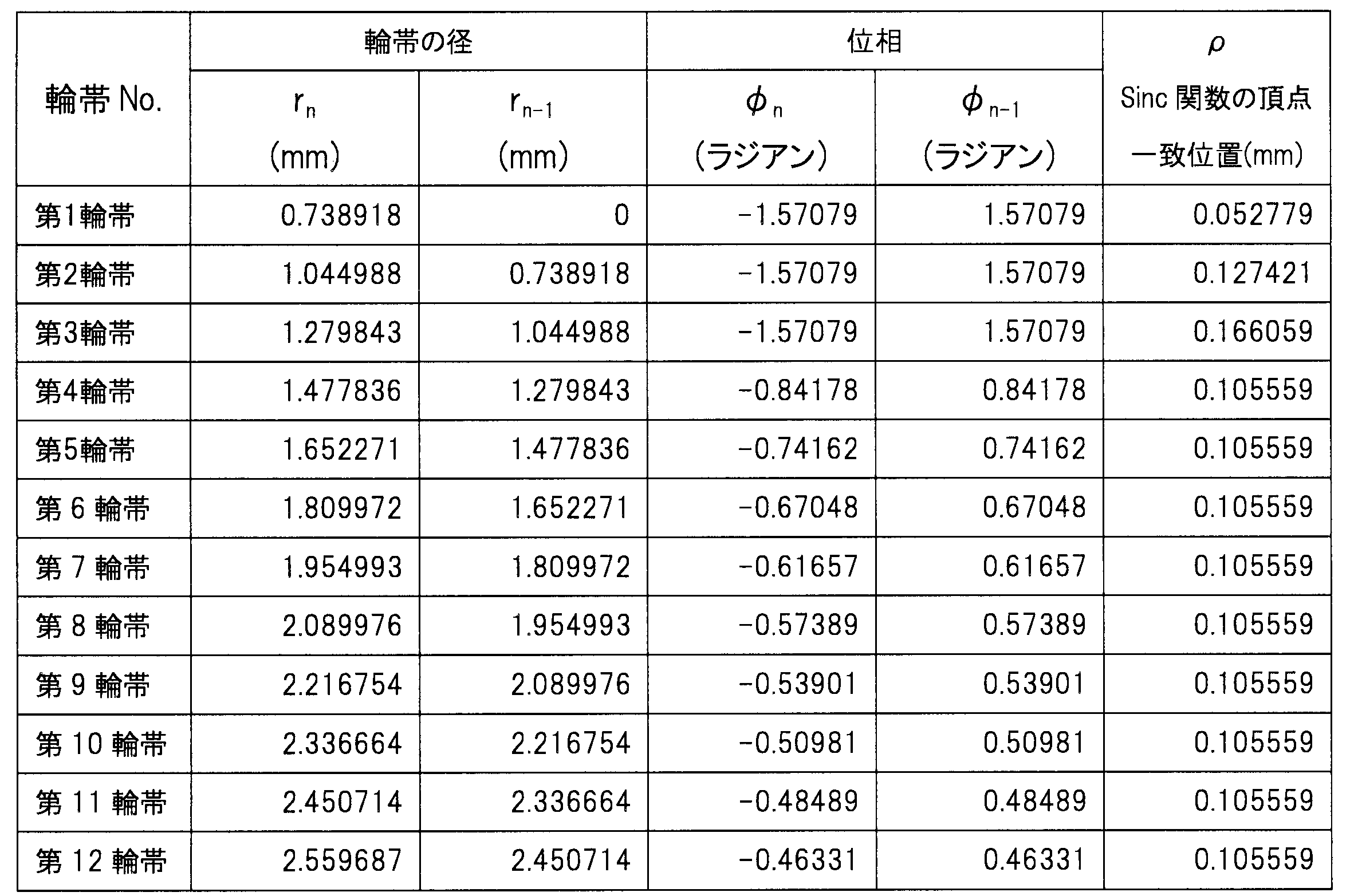
本実施形態の特徴を明確にするために、本実施形態のSinc関数の計算結果を図39に示す。本実施形態が本発明の第一の実施形態と異なるのは、第1~3輪帯だけはブレーズの位相定数をh=0.5とし、Sinc関数が最大となる位置を他の輪帯と等しくしていないところである。本図と比較例を示す図7を比べると、明らかにSinc関数の広がりが低減されており、かつ図8の第一の実施形態とさほど変わらないSinc関数の広がりを示しており、ハロの低減が期待できることが分かる。このようにすべての輪帯で同じ位置にSinc関数が最大となる位置を持ってこなくても、本発明の第一の実施形態と同様に、ハロの低減効果が見込まれるのである。
In order to clarify the feature of the present embodiment, the calculation result of the Sinc function of the present embodiment is shown in FIG. The present embodiment differs from the first embodiment of the present invention in that the phase constant of the blaze is h = 0.5 only in the first to third ring zones, and the position where the Sinc function is maximum is the other ring zone It is the place which is not equal. Comparing FIG. 7 showing this figure with the comparative example, the spread of the Sinc function is clearly reduced, and the spread of the Sinc function which is not so different from that of the first embodiment of FIG. Can be expected. Even if the position where the Sinc function is maximized is not reached at the same position in all the ring zones, as in the first embodiment of the present invention, a halo reduction effect can be expected.
図40に、本実施形態の0次回折光の焦点像面の強度分布について、計算機上でシミュレートした結果を示す。なお、本実施形態に対する比較例の像面強度分布は前記図9(b)に示されている。図9(b)に示す比較例と比べることにより、本実施形態において明らかにサイドバンドの強度が低減されていることが確認できる。
FIG. 40 shows the result of simulating on a computer the intensity distribution of the focal image plane of the zeroth-order diffracted light of this embodiment. The image plane intensity distribution of the comparative example to the present embodiment is shown in FIG. 9 (b). By comparing with the comparative example shown in FIG. 9B, it can be confirmed that the intensity of the sideband is clearly reduced in the present embodiment.
図41に、図38に示す本実施形態に従うブレーズ形状によって得られる光軸上の強度分布について、計算機上でシミュレートした結果を示す。本図は、光の入射する開口径を変えた時の光軸上の強度分布の変化を見たもので、開口径が小、中、大と変化しても近方と遠方の両領域に焦点が生成する、すなわち多焦点眼用レンズとして機能しうるものであることが分かる。また、明るい室内における光軸上の強度パターン(図41(b))は比較例(図11(d))とほぼ同じであることから、本実施形態の回折レンズでは標準的なフレネル間隔型と同等の遠近の見え方を与えつつ、ハロ低減に効果をもたらすものであることも分かるのである。
FIG. 41 shows a computer simulation result of the intensity distribution on the optical axis obtained by the blazed shape according to the present embodiment shown in FIG. This figure shows the change in the intensity distribution on the optical axis when the aperture diameter where light is incident is changed. Even if the aperture diameter changes from small to medium to large, both in the near and far regions It can be seen that the focus is generated, ie it can function as a multifocal ophthalmic lens. In addition, since the intensity pattern on the optical axis in the bright room (FIG. 41 (b)) is almost the same as the comparative example (FIG. 11 (d)), the diffractive lens of this embodiment It is also understood that it is effective for halo reduction while giving an equivalent perspective view.
図42に、本発明の第一の実施形態の変形例3の位相プロファイル54を示す。本実施形態では、表16に示すように、12個の輪帯からなる回折構造20の格子ピッチが第一の実施形態と同じフレネル間隔で構成されたものである。なお、位相φn,φn-1は表16に示すように設定されている。なお、本実施例の比較例として、同じ12個の輪帯数からなり、明るい室内での光軸上の強度パターンが本実施形態とほぼ同じになるように位相定数h=0.4一定としたものであり、第一の実施形態で示したものと同じものである(図4b及び表2参照のこと)。
FIG. 42 shows a phase profile 54 of Modification 3 of the first embodiment of the present invention. In the present embodiment, as shown in Table 16, the grating pitch of the diffractive structure 20 consisting of 12 ring zones is configured with the same Fresnel distance as that of the first embodiment. The phases φ n and φ n-1 are set as shown in Table 16. As a comparative example of the present embodiment, it is assumed that the same number of annular zones is used and the phase constant h = 0.4 is constant so that the intensity pattern on the optical axis in a bright room becomes substantially the same as that of the present embodiment. And the same as shown in the first embodiment (see FIG. 4 b and Table 2).

本実施形態の特徴を明確にするために、本実施形態のSinc関数の計算結果を図43に示す。本実施形態が本発明の第一の実施形態と異なるのは、第2~4輪帯は、ρ=0.1266mm(図中矢印B)で、第5~12輪帯は、ρ=0.0897mm(図中矢印A)でそれぞれSinc関数の頂点が一致するようにしたものである。つまり、頂点が一致する位置を各輪帯領域で異ならせたところである。本図と比較例を示す図7を比べると、明らかにSinc関数の広がりが低減されており、ハロの低減が期待できることが分かる。このようにすべての輪帯で同じ位置にSinc関数が最大となる位置を持ってこなくても、本発明の第一の実施形態と同様に、ハロの低減効果が見込まれるのである。
In order to clarify the feature of this embodiment, the calculation result of the Sinc function of this embodiment is shown in FIG. The present embodiment is different from the first embodiment of the present invention in that the second to fourth ring zones are ρ = 0.1266 mm (arrow B in the figure), and the fifth to twelfth ring zones are = 0. = 0. At 0897 mm (arrow A in the figure), the vertices of the sinc function are made to coincide with each other. That is, the positions where the apexes coincide are different in each orbicular zone area. Comparing FIG. 7 showing this figure with the comparative example, it can be seen that the spread of the Sinc function is clearly reduced and halo reduction can be expected. Even if the position where the Sinc function is maximized is not reached at the same position in all the ring zones, as in the first embodiment of the present invention, a halo reduction effect can be expected.
図44に、本実施形態の0次回折光の焦点像面の強度分布について、計算機上でシミュレートした結果を示す。なお、本実施形態に対する比較例の像面強度分布は前記図9(b)に示されている。図9(b)に示す比較例と比べることにより、本実施形態において明らかにサイドバンドの強度が低減されていることが確認できる。
FIG. 44 shows the result of simulation on a computer about the intensity distribution of the focal image plane of 0th order diffracted light of this embodiment. The image plane intensity distribution of the comparative example to the present embodiment is shown in FIG. 9 (b). By comparing with the comparative example shown in FIG. 9B, it can be confirmed that the intensity of the sideband is clearly reduced in the present embodiment.
図45に、図42に示す本実施形態に従うブレーズ形状によって得られる光軸上の強度分布について、計算機上でシミュレートした結果を示す。本図は、光の入射する開口径を変えた時の光軸上の強度分布の変化を見たもので、開口径が小、中、大と変化しても近方と遠方の両領域に焦点が生成する、すなわち多焦点眼用レンズとして機能しうるものであることが分かる。また、明るい室内における光軸上の強度パターン(図45(b))は比較例(図11(d))とほぼ同じであることから、本実施形態の回折レンズでは標準的なフレネル間隔型と同等の遠近の見え方を与えつつ、ハロ低減に効果をもたらすものであることも分かるのである。
FIG. 45 shows the result of computer simulation of the intensity distribution on the optical axis obtained by the blazed shape according to the present embodiment shown in FIG. This figure shows the change in the intensity distribution on the optical axis when the aperture diameter where light is incident is changed. Even if the aperture diameter changes from small to medium to large, both in the near and far regions It can be seen that the focus is generated, ie it can function as a multifocal ophthalmic lens. Further, since the intensity pattern on the optical axis in the bright room (FIG. 45 (b)) is almost the same as the comparative example (FIG. 11 (d)), the diffractive lens of this embodiment It is also understood that it is effective for halo reduction while giving an equivalent perspective view.
ここまでの、第一の実施形態並びにその変形例についての説明から、Sinc関数の頂点は必ずしも全ての輪帯で一致する必要はないことが分かった。つまり、複数の輪帯(ゾーン)で一致してさえいれば、程度の差はあるものの、Sinc関数の広がりが抑えられ、ハロの軽減ができるのである。以上のことから、複数の輪帯(ゾーン)で数2を満足する領域を有していれば良いことが、数19より導かれる。
From the above description of the first embodiment and its modification, it has been found that the vertices of the Sinc function do not necessarily have to coincide in all the ring zones. In other words, as long as they coincide with each other in a plurality of zones (zones), the spread of the Sinc function can be suppressed to a lesser extent, and halos can be reduced. From the above, it is derived from Eq. 19 that it is only necessary to have a region satisfying Eq. 2 in a plurality of ring zones (zones).
図46(a)に、本発明の第二の実施形態の変形例1としての位相プロファイル56を示す。本実施形態では、表17に示すように、6個の輪帯からなる回折構造20の格子ピッチが第一の実施形態と同じフレネル間隔で構成されたものである。なお、位相φn,φn-1は表17に示すように設定されている。一方、図46(b)に比較例の位相プロファイル58を示す。本比較例は表18に示すように、本実施形態と同じ6つの輪帯数がフレネル間隔で構成されたものであり、明るい室内での光軸上の強度パターンが本実施形態とほぼ同じになるように位相定数h=0.44一定としたものである。
FIG. 46 (a) shows a phase profile 56 as a first modification of the second embodiment of the present invention. In the present embodiment, as shown in Table 17, the grating pitch of the diffractive structure 20 consisting of six orbicular zones is configured with the same Fresnel distance as in the first embodiment. The phases φ n and φ n-1 are set as shown in Table 17. On the other hand, FIG. 46 (b) shows a phase profile 58 of the comparative example. In this comparative example, as shown in Table 18, the same six ring numbers as in this embodiment are formed by Fresnel intervals, and the intensity pattern on the optical axis in a bright room is almost the same as in this embodiment. Thus, the phase constant h is fixed at 0.44.


本実施形態の特徴を明確にするために、本実施形態のSinc関数の計算結果を図47(a)に示す。本実施形態が本発明の第二の実施形態と異なるのは、第1輪帯を除いて第2輪帯~6輪帯までがρ=0.5mmの位置でSinc関数の節(β=1)が一致しており、一致するρが少し大きくなっている点である。本図を、図47(b)の比較例のSinc関数の計算結果と比較すると明らかにSinc関数の広がりは低減しており、また、本発明の第二の実施形態を示す図13を比べても、Sinc関数の広がり具合は遜色ない。このように節を位置させる像面上の位置ρの値を変量しても、本発明の第二の実施形態と同様に、ハロの低減効果が見込まれるのである。
In order to clarify the feature of this embodiment, the calculation result of the Sinc function of this embodiment is shown in FIG. 47 (a). The present embodiment is different from the second embodiment of the present invention in that the nodes of the Sinc function (β = 1 at the position where == 0.5 mm in the second to sixth ring zones except the first ring zone) ) Is a point of coincidence, and the point of coincidence ρ is a little larger. The spread of the Sinc function is clearly reduced when this figure is compared with the calculation result of the Sinc function of the comparative example of FIG. 47 (b), and FIG. 13 showing the second embodiment of the present invention is compared. Also, the spread of the Sinc function is not inferior. Even if the value of the position ρ on the image plane where the nodes are positioned is thus varied, the halo reduction effect can be expected as in the second embodiment of the present invention.
図48(a)に本実施形態の、図48(b)に比較例の0次回折光の焦点像面の強度分布について計算機上でシミュレートした結果をそれぞれ示す。比較例と比べると、サイドバンドの強度分布の範囲が狭まっていることが分かる。
FIG. 48 (a) shows the results of simulation on a computer about the intensity distribution of the focal image plane of the zeroth-order diffracted light of the comparative example of this embodiment and FIG. 48 (b) of this embodiment. As compared with the comparative example, it can be seen that the range of the intensity distribution of the sidebands is narrowed.
図49に、図46(a)に示す本実施形態に従うブレーズ形状によって得られる光軸上の強度分布について、計算機上でシミュレートした結果を示す。本図は、光の入射する開口径を変えた時の光軸上の強度分布の変化を見たもので、開口径が小、中、大と変化しても近方と遠方の両領域に焦点が生成する、すなわち多焦点眼用レンズとして機能しうるものであることが分かる。図16の前記第二の実施形態と比較すると、明るい室内の環境下での近方焦点の強度が増しており、より近くが見やすい多焦点眼用レンズとなっていることが分かる。また、明るい室内における光軸上の強度パターン(図49(b))は比較例(図49(d))とほぼ同じであることから、本実施形態の回折レンズでは標準的なフレネル間隔型と同等の遠近の見え方を与えつつ、ハロ低減に効果をもたらすものであることも分かるのである。
FIG. 49 shows a computer simulation result of the intensity distribution on the optical axis obtained by the blazed shape according to the present embodiment shown in FIG. 46 (a). This figure shows the change in the intensity distribution on the optical axis when the aperture diameter where light is incident is changed. Even if the aperture diameter changes from small to medium to large, both in the near and far regions It can be seen that the focus is generated, ie it can function as a multifocal ophthalmic lens. Compared to the second embodiment of FIG. 16, it can be seen that the intensity of the near focal point in the bright indoor environment is increased, and the multifocal ophthalmic lens that is easy to see near is obtained. Further, since the intensity pattern on the optical axis in the bright room (FIG. 49 (b)) is almost the same as the comparative example (FIG. 49 (d)), the diffractive lens of this embodiment It is also understood that it is effective for halo reduction while giving an equivalent perspective view.
図50(a)に、本発明の第二の実施形態の変形例2としての位相プロファイル60を示す。本実施形態は、表19に示すように8つの輪帯からなる回折構造20の格子ピッチが第一の実施形態と同じフレネル間隔で構成されたものである。なお、位相φn,φn-1は表19に示すように設定されている。一方、図50(b)に比較例 の位相プロファイル62を示す。本比較例は表20に示すように、本実施形態と同じ8つの輪帯数がフレネル間隔で構成されたものであり、明るい室内での光軸上の強度パターンが本実施形態とほぼ同じになるように位相定数h=0.5一定としたものである。
FIG. 50 (a) shows a phase profile 60 as a modified example 2 of the second embodiment of the present invention. In the present embodiment, as shown in Table 19, the grating pitch of the diffractive structure 20 consisting of eight orbicular zones is configured with the same Fresnel distance as that of the first embodiment. The phases φ n and φ n-1 are set as shown in Table 19. On the other hand, FIG. 50 (b) shows a phase profile 62 of the comparative example. In this comparative example, as shown in Table 20, the same eight ring numbers as in this embodiment are formed by Fresnel intervals, and the intensity pattern on the optical axis in a bright room is almost the same as in this embodiment. Thus, the phase constant h = 0.5 is constant.


本実施形態の特徴を明確にするために、本実施形態のSinc関数の計算結果を図51に示す。本実施形態が本発明の第二の実施形態と異なるのは、第2輪帯のSinc関数の値が0になる位置(節)をβ=2の節とし、第3~8輪帯のSinc関数の値が0になる位置(節)(β=1)とρ=0.6mmの地点で等しくしたところである。本実施形態では節の一致するρ位置を第二の実施形態及びその変形例1よりも少し大きくしたものであり、その分Sinc関数の広がりは少し大きくなっている。しかし、図18(b)の比較例の第1~8輪帯のSinc関数の広がりと比較すると全体の広がりは抑制されており、ハロの低減が期待されるものである。
In order to clarify the feature of this embodiment, the calculation result of the Sinc function of this embodiment is shown in FIG. This embodiment differs from the second embodiment of the present invention in that the position (node) where the value of the Sinc function of the second annular zone is 0 is a node at β = 2, and the third to eighth annular zones Sinc The position (node) (β = 1) at which the value of the function is 0 and the point where ρ = 0.6 mm are equal. In this embodiment, the ρ position where the nodes coincide is slightly larger than that of the second embodiment and the first modification thereof, and the spread of the Sinc function is a little larger accordingly. However, as compared with the spread of the Sinc function of the first to eighth rings in the comparative example of FIG. 18 (b), the entire spread is suppressed, and reduction of halo is expected.
図52(a)に、本実施形態の、図52(b)に比較例の0次回折光の焦点像面の強度分布について、計算機上でシミュレートした結果を示す。比較例と比べると、ρ=0.45~0.6mm付近のサイドバンド強度が減少しており、強度分布の範囲が狭まっていることが分かる。このようにSinc関数が0になる位置(節)のβの値が異なっていても、本発明の第二の実施形態と同様に、ハロの低減効果が見込まれるのである。
FIG. 52 (a) shows the result of simulation on a computer about the intensity distribution of the focal image plane of the zero-order diffracted light of the comparative example in FIG. 52 (b) of this embodiment. As compared with the comparative example, it can be seen that the sideband intensity in the vicinity of 45 = 0.45 to 0.6 mm is reduced, and the range of the intensity distribution is narrowed. Even if the value of β at the position (node) where the Sinc function becomes 0 as described above is different, the halo reduction effect can be expected as in the second embodiment of the present invention.
図53に、図50(a)に示す本実施形態に従うブレーズ形状によって得られる光軸上の強度分布について、計算機上でシミュレートした結果を示す。本図は、光の入射する開口径を変えた時の光軸上の強度分布の変化を見たもので、開口径が小、中、大と変化しても近方と遠方の両領域に焦点が生成する、すなわち多焦点眼用レンズとして機能しうるものであることが分かる。なお、本実施形態は節の一致するρ位置を第2の実施形態及びその変形例1よりも少し大きくしたものであり、その分、Sinc関数の広がりは少し大きくなり、像面のサイドバンドの強度分布も少し広がっているが、近方焦点の強度は増しており、その結果、前記2つの実施形態より、遠方と近方の見え方はよりバランスが取れたものとなっている。また、明るい室内における光軸上の強度パターン(図53(b))は比較例(図20(d))とほぼ同じであることから、本実施形態の回折レンズでは標準的なフレネル間隔型と同等の遠近の見え方を与えつつ、ハロ低減に効果をもたらすものであることも分かるのである。
FIG. 53 shows the result of computer simulation of the intensity distribution on the optical axis obtained by the blazed shape according to the present embodiment shown in FIG. 50 (a). This figure shows the change in the intensity distribution on the optical axis when the aperture diameter where light is incident is changed. Even if the aperture diameter changes from small to medium to large, both in the near and far regions It can be seen that the focus is generated, ie it can function as a multifocal ophthalmic lens. In this embodiment, the ρ position where the nodes coincide with each other is slightly larger than that of the second embodiment and the first modification thereof, and the spread of the Sinc function becomes a little larger accordingly, and the sidebands of the image plane The intensity distribution is also slightly broadened, but the intensity of the near focus is increased, resulting in a more balanced view of the distance and the near than the two embodiments. Moreover, since the intensity pattern on the optical axis in the bright room (FIG. 53 (b)) is almost the same as the comparative example (FIG. 20 (d)), the diffractive lens of this embodiment It is also understood that it is effective for halo reduction while giving an equivalent perspective view.
図54(a)に、本発明の第三の実施形態の変形例1としての位相プロファイル64形状の拡大断面図を示す。本実施形態は、表21に示すように7つの輪帯からなる回折構造20の格子ピッチが第一の実施形態と同じフレネル間隔で構成されたものである。なお、位相φn,φn-1は表21に示すように設定されている。一方、図54(b)に比較例の位相プロファイル66を示す。本比較例は表22に示すように、本実施形態と同じ7つの輪帯数がフレネル間隔で構成されたものであり、明るい室内での光軸上の強度パターンが本実施形態とほぼ同じになるように位相定数h=0.6一定としたものである。
FIG. 54 (a) shows an enlarged cross-sectional view of the shape of the phase profile 64 as a first modification of the third embodiment of the present invention. In the present embodiment, as shown in Table 21, the grating pitch of the diffractive structure 20 consisting of seven orbicular zones is configured with the same Fresnel distance as in the first embodiment. The phases φ n and φ n-1 are set as shown in Table 21. On the other hand, FIG. 54 (b) shows a phase profile 66 of the comparative example. In this comparative example, as shown in Table 22, the same seven ring numbers as in this embodiment are formed by Fresnel intervals, and the intensity pattern on the optical axis in a bright room is almost the same as in this embodiment. Thus, the phase constant h = 0.6 is constant.


本実施形態の特徴を明確にするために、本実施形態のSinc関数の計算結果を図55(a)に示す。また、比較例のSinc関数の計算結果を図55(b)に示す。本実施形態が本発明の第三の実施形態と異なるのは、第1輪帯は対象外とし、第2輪帯のSinc関数の値が極値になる位置(α=2)を第3~7輪帯のSinc関数の値が極値になる位置(α=1)とρ=0.8mmの地点で等しくしたところである。図55(b)に示す比較例のSinc関数の広がりと比較すると明らかに全体の広がりは抑制されたものとなっていることが分かる。
In order to clarify the feature of the present embodiment, the calculation result of the Sinc function of the present embodiment is shown in FIG. 55 (a). Moreover, the calculation result of the Sinc function of a comparative example is shown in FIG.55 (b). The present embodiment differs from the third embodiment of the present invention in that the first ring zone is excluded and the position (α = 2) at which the value of the Sinc function of the second ring zone becomes an extreme value is the third to the third The position (α = 1) at which the value of the Sinc function of the seven-ring zone becomes an extreme value is equal at the point where == 0.8 mm. As compared with the spread of the Sinc function of the comparative example shown in FIG. 55 (b), it is apparent that the entire spread is suppressed.
図56(a)に本実施形態の、図56(b)に比較例の0次回折光の焦点像面の強度分布について、計算機上でシミュレートした結果をそれぞれ示す。(b)に示す比較例と比べると、サイドバンドの強度分布の範囲が狭まっていることが分かる。このようにSinc関数の値が極値になる位置をすべての輪帯で等しくなくても、またSinc関数が極値になる位置のαの値が異なっていても、本発明の第三の実施形態と同様に、ハロの低減効果が見込まれるのである。
FIG. 56 (a) shows simulated results of the intensity distribution of the focal image plane of the zeroth-order diffracted light of the comparative example of the present embodiment and FIG. 56 (b), respectively, on a computer. As compared with the comparative example shown in (b), it is understood that the range of the intensity distribution of the side band is narrowed. As described above, the third embodiment of the present invention does not require that the position where the value of the Sinc function becomes an extremum is not equal in all the ring zones, and even if the value of α at the position where the Sinc function becomes an extremum is different. As with the form, halo reduction effects are expected.
図57に、図54(a)に示す本実施形態に従うブレーズ形状によって得られる光軸上の強度分布について、計算機上でシミュレートした結果を示す。また、図57(d)は、開口径3.3mmでの比較例の光軸上の強度分布を示している。本図は、光の入射する開口径を変えた時の光軸上の強度分布の変化を見たもので、開口径が小、中、大と変化しても近方と遠方の両領域に焦点が生成する、すなわち多焦点眼用レンズとして機能しうるものであることが分かる。また、明るい室内における光軸上の強度パターンは比較例とほぼ同じであることから、本実施形態の回折レンズでは標準的なフレネル間隔型と同等の遠近の見え方を与えつつ、ハロ低減に効果をもたらすものであることも分かるのである。
FIG. 57 shows the result of computer simulation of the intensity distribution on the optical axis obtained by the blazed shape according to the present embodiment shown in FIG. 54 (a). FIG. 57 (d) shows the intensity distribution on the optical axis of the comparative example at an aperture diameter of 3.3 mm. This figure shows the change in the intensity distribution on the optical axis when the aperture diameter where light is incident is changed. Even if the aperture diameter changes from small to medium to large, both in the near and far regions It can be seen that the focus is generated, ie it can function as a multifocal ophthalmic lens. In addition, since the intensity pattern on the optical axis in the bright room is almost the same as that of the comparative example, the diffractive lens of this embodiment is effective in halo reduction while giving the same perspective as the standard Fresnel interval type. It is also understood that the
以上、本発明の実施形態として、各輪帯のSinc関数を特徴的な位置(頂点、0となる点(節)、極値をとる点)で一致させるための条件を示した。ただし、本発明ではこれらの位置に限らず、全体の振幅分布の広がりを抑制できる一致点は他にも存在するので、他の位置で一致させてもよい。たとえばSinc関数の最大振幅の90%、80%、70%、・・・の振幅となる地点など、様々な点が考えられる。
As described above, as the embodiment of the present invention, conditions for making the Sinc function of each ring zone coincide at a characteristic position (apex, a point (node) which is 0, a point having an extreme value) are shown. However, the present invention is not limited to these positions, and there are other coincident points that can suppress the spread of the entire amplitude distribution, and therefore, they may be coincident at other positions. For example, various points can be considered such as 90%, 80%, 70%,... Of the maximum amplitude of the Sinc function.
各輪帯のSinc関数を特徴的な位置で一致させる場合、必ずしも全ての輪帯で一致する必要はなく、たとえば第1~(j-1)輪帯までと第j~n輪帯まではそれぞれ別の位置で一致していても構わない。またSinc関数が0になる位置は上述のようにたくさんあるが、同じ位置で一致しても良いし、異なる位置で一致しても良い。同じくSinc関数が極値をとる位置もたくさんあるが、同じ位置で一致しても良いし、異なる位置で一致しても良い。また一致する位置は、全ての輪帯に対してでなくても良く、輪帯の一部や輪帯の複数の異なる領域に対してでもよい。さらに、一致する位置は、各輪帯で異なる特徴的な位置であっても良い。つまり、標準的な回折構造の中に本発明に基づく回折構造が一部組み込まれたものも好適な例である。
When the Sinc function of each ring zone is matched at a characteristic position, the ring zones need not necessarily coincide with each other. For example, the 1st to (j-1) th ring zones and the jth to n ring zones respectively It does not matter if they match at another position. As described above, there are many positions where the sinc function becomes 0, but they may coincide at the same position or may coincide at different positions. Similarly, there are many positions where the Sinc function takes extreme values, but they may coincide at the same position or at different positions. Further, the matching position may not be for all the ring zones, but may be for a part of the ring zone or a plurality of different areas of the ring zone. Furthermore, the matching position may be a different characteristic position in each orbicular zone. That is, those in which the diffractive structure according to the present invention is partially incorporated into a standard diffractive structure are also suitable examples.
なお、頂点、節、極小値を一致させる像面上での位置ρは、0次回折光の焦点距離f(mm)に依存するため、fを包含した下記式によって好適なρの範囲を定めることができる。本発明におけるρの範囲としては、0≦ρ≦0.0105f(mm)であり、好ましくは0.0002f(mm)≦ρ≦0.007f(mm)である。
In addition, since the position で on the image plane for making the apex, the node, and the minimum value coincide with each other depends on the focal length f (mm) of zero-order diffracted light, a suitable range of ρ should be determined by the following equation including f. Can. The range of ρ in the present invention is 0 ≦ ρ ≦ 0.0105 f (mm), preferably 0.0002 f (mm) ≦ ρ ≦ 0.007 f (mm).
本実施形態では回折構造の輪帯間隔は全てフレネル間隔からなるもので示したが、かかる間隔に依らなくても、本発明にて示した関係式は成立することは明らかである。よって、フレネル間隔以外の間隔を有する回折構造に対しても本発明は好適に利用できるものである。
In the present embodiment, the ring-shaped intervals of the diffractive structure are all made of Fresnel intervals, but it is apparent that the relational expression shown in the present invention holds even without depending on such intervals. Therefore, the present invention can be suitably used for a diffractive structure having a spacing other than the Fresnel spacing.
なお、前記各実施形態などで示された回折構造は目的とする眼用レンズの前面、または後面のどちらかに別々に設定されてもよいし、あるいは同一面に設定されてもよい。あるいはレンズの内部に設置されていてもよい。
The diffractive structures shown in the above-described embodiments and the like may be separately set on the front surface or the rear surface of the intended ophthalmic lens, or may be set on the same surface. Alternatively, it may be installed inside the lens.
なお、本発明における眼用レンズとしてはコンタクトレンズ、眼鏡、眼内レンズなどが具体的な対象となる。さらには角膜実質内に埋植して視力を矯正する角膜挿入レンズ、あるいは人工角膜などにも適用可能である。コンタクトレンズにおいては硬質性の酸素透過性ハードコンタクトレンズ、含水または非含性のソフトコンタクトレンズ、さらにはシリコーン成分を含有した酸素透過性の含水または非含水性のソフトコンタクトレンズなどに好適に用いることができる。また、眼内レンズにおいても硬質性の眼内レンズや、折り畳んで眼内に挿入可能な軟質眼内レンズなど、いずれの眼内レンズにも好適に用いることができる。
In addition, as an ophthalmic lens in this invention, a contact lens, spectacles, an intraocular lens etc. become a concrete object. Furthermore, the present invention is also applicable to a cornea insert lens or an artificial cornea which is implanted in the corneal stroma to correct vision. In contact lenses, preferably used for hard oxygen-permeable hard contact lenses, water-containing or non-containing soft contact lenses, and oxygen-permeable water-containing or non-water-containing soft contact lenses containing a silicone component Can. In addition, the present invention can be suitably used for any intraocular lens such as a hard intraocular lens in an intraocular lens and a soft intraocular lens that can be folded and inserted into the eye.
10:眼用レンズ、12:光学部、16:光学部後面、18:レンズ中心軸、20:回折構造、21:ブレーズ
10: Ophthalmic lens, 12: optical part, 16: optical part rear surface, 18: lens central axis, 20: diffractive structure, 21: blaze
Claims (7)
- 同心円状の複数のゾーンを有する回折構造が形成された回折型多焦点眼用レンズにおいて、
前記各ゾーンがブレーズ形の位相関数を有していると共に、
該各ゾーンにおいて下式で表される関数gn(ρ)が、複数の該ゾーン間において頂点と節と極値の何れかで相互に一致していることを特徴とする回折型多焦点眼用レンズ。

Each of the zones has a blazed phase function, and
A diffractive multifocal eye characterized in that in each of the zones, a function g n (式) expressed by the following equation is mutually coincident at any of a vertex, a node and an extremum among a plurality of the zones. Lens.
- 前記回折構造が、複数の前記ゾーンが下式を満足する領域を有している請求項1に記載の回折型多焦点眼用レンズ。

- 前記回折構造が、複数の前記ゾーンが下式を満足する領域を有している請求項1に記載の回折型多焦点眼用レンズ。
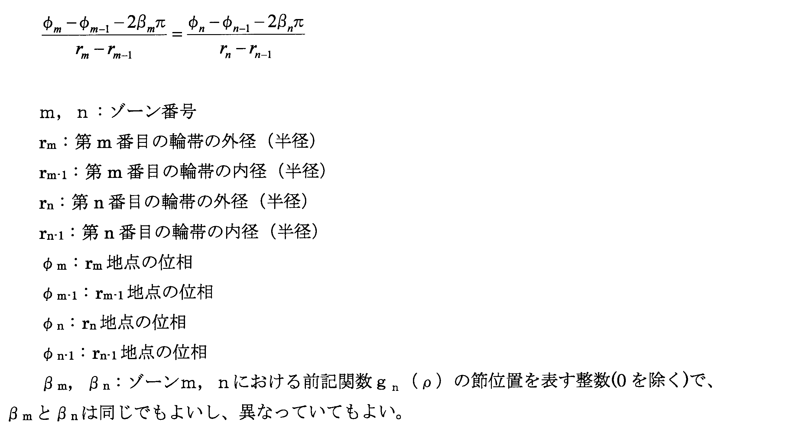
- 前記回折構造が、複数の前記ゾーンが下式を満足する領域を有している請求項1に記載の回折型多焦点眼用レンズ。

- 前記回折構造の0次回折光により遠方視用焦点が設定されていると共に、該回折構造の+1次回折光により近方視用焦点が設定されている請求項1~4の何れか一項に記載の回折型多焦点眼用レンズ。 5. The focus for far vision is set by the zeroth order diffracted light of the diffractive structure, and the focus for near vision is set by the + 1st order diffracted light of the diffractive structure. Diffractive multifocal eye lens.
- 同心円状の複数のゾーンを有する回折構造が形成された回折型多焦点眼用レンズを製造するに際して、
前記各ゾーンの位相関数をブレーズ形として、目標とする回折光の焦点位置を設定する工程と、
該各ゾーンにおいて下式で表される関数gn(ρ)を求める工程と、
前記各ゾーンにおける前記関数gn(ρ)が、複数の該ゾーン間において一致点を設定して前記ブレーズ形状を決定する工程と
を、含む回折型多焦点眼用レンズの製造方法。

Setting the focal point position of the target diffracted light as a blazed phase function of each of the zones;
Determining a function g n (ρ) represented by the following equation in each of the zones:
And D. the function g n (ρ) in each of the zones sets a coincidence point between a plurality of the zones to determine the blazed shape.
- 前記一致点が、複数の前記ゾーン間において頂点と節と極値の何れかに設定されている請求項6に記載の回折型多焦点眼用レンズの製造方法。 The method for manufacturing a diffractive multifocal ophthalmic lens according to claim 6, wherein the coincident points are set to any one of a vertex, a node and an extreme value between the plurality of zones.
Priority Applications (2)
| Application Number | Priority Date | Filing Date | Title |
|---|---|---|---|
| PCT/JP2012/000859 WO2013118177A1 (en) | 2012-02-09 | 2012-02-09 | Diffraction-type multifocal eye lens and manufacturing method therefor |
| JP2013557235A JP5824076B2 (en) | 2012-02-09 | 2012-02-09 | Diffractive multifocal ophthalmic lens and manufacturing method thereof |
Applications Claiming Priority (1)
| Application Number | Priority Date | Filing Date | Title |
|---|---|---|---|
| PCT/JP2012/000859 WO2013118177A1 (en) | 2012-02-09 | 2012-02-09 | Diffraction-type multifocal eye lens and manufacturing method therefor |
Publications (1)
| Publication Number | Publication Date |
|---|---|
| WO2013118177A1 true WO2013118177A1 (en) | 2013-08-15 |
Family
ID=48946996
Family Applications (1)
| Application Number | Title | Priority Date | Filing Date |
|---|---|---|---|
| PCT/JP2012/000859 WO2013118177A1 (en) | 2012-02-09 | 2012-02-09 | Diffraction-type multifocal eye lens and manufacturing method therefor |
Country Status (2)
| Country | Link |
|---|---|
| JP (1) | JP5824076B2 (en) |
| WO (1) | WO2013118177A1 (en) |
Cited By (15)
| Publication number | Priority date | Publication date | Assignee | Title |
|---|---|---|---|---|
| CN104127263A (en) * | 2013-12-19 | 2014-11-05 | 爱博诺德(北京)医疗科技有限公司 | Multi-focus artificial lens |
| WO2015159374A1 (en) * | 2014-04-15 | 2015-10-22 | 株式会社メニコン | Diffractive multifocal intraocular lens and method for manufacturing diffractive multifocal intraocular lens |
| WO2020194712A1 (en) * | 2019-03-28 | 2020-10-01 | 株式会社ニコン | Ophthalmic lens and method for producing ophthalmic lens |
| WO2020194713A1 (en) * | 2019-03-28 | 2020-10-01 | 株式会社ニコン | Ophthalmic lens and ophthalmic lens production method |
| US10792147B2 (en) | 2018-08-09 | 2020-10-06 | Nikon Corporation | Ophthalmic lens and method of manufacturing ophthalmic lens |
| US11022815B2 (en) | 2012-08-31 | 2021-06-01 | Amo Groningen B.V. | Multi-ring lens, systems and methods for extended depth of focus |
| CN113345619A (en) * | 2021-06-16 | 2021-09-03 | 中国工程物理研究院激光聚变研究中心 | One-dimensional X-ray refraction blazed zone plate |
| US11156853B2 (en) | 2017-06-28 | 2021-10-26 | Amo Groningen B.V. | Extended range and related intraocular lenses for presbyopia treatment |
| JP6996089B2 (en) | 2017-02-24 | 2022-02-04 | 株式会社ニコン | Diffractive optical elements, optical systems and optical equipment |
| US11262598B2 (en) | 2017-06-28 | 2022-03-01 | Amo Groningen, B.V. | Diffractive lenses and related intraocular lenses for presbyopia treatment |
| US11327210B2 (en) | 2017-06-30 | 2022-05-10 | Amo Groningen B.V. | Non-repeating echelettes and related intraocular lenses for presbyopia treatment |
| US11497599B2 (en) | 2017-03-17 | 2022-11-15 | Amo Groningen B.V. | Diffractive intraocular lenses for extended range of vision |
| US11523897B2 (en) | 2017-06-23 | 2022-12-13 | Amo Groningen B.V. | Intraocular lenses for presbyopia treatment |
| WO2022263994A1 (en) * | 2021-06-14 | 2022-12-22 | Alcon Inc. | Multifocal diffractive silicone hydrogel contact lenses |
| US11844689B2 (en) | 2019-12-30 | 2023-12-19 | Amo Groningen B.V. | Achromatic lenses and lenses having diffractive profiles with irregular width for vision treatment |
Families Citing this family (1)
| Publication number | Priority date | Publication date | Assignee | Title |
|---|---|---|---|---|
| CN112198577B (en) * | 2019-10-23 | 2022-04-26 | 东莞东阳光医疗智能器件研发有限公司 | Ophthalmic lens |
Citations (4)
| Publication number | Priority date | Publication date | Assignee | Title |
|---|---|---|---|---|
| JPH02137814A (en) * | 1987-11-12 | 1990-05-28 | Allen L Cohen | Contact lens |
| JP2009525840A (en) * | 2006-02-09 | 2009-07-16 | アルコン リサーチ, リミテッド | Pseudo-tuning IOL with multiple diffraction patterns |
| JP2010134282A (en) * | 2008-12-05 | 2010-06-17 | Hoya Corp | Diffractive multifocal lens |
| JP2010528718A (en) * | 2007-06-01 | 2010-08-26 | ボシュ・アンド・ロム・インコーポレイテッド | Diffractive intraocular lens |
-
2012
- 2012-02-09 JP JP2013557235A patent/JP5824076B2/en active Active
- 2012-02-09 WO PCT/JP2012/000859 patent/WO2013118177A1/en active Application Filing
Patent Citations (4)
| Publication number | Priority date | Publication date | Assignee | Title |
|---|---|---|---|---|
| JPH02137814A (en) * | 1987-11-12 | 1990-05-28 | Allen L Cohen | Contact lens |
| JP2009525840A (en) * | 2006-02-09 | 2009-07-16 | アルコン リサーチ, リミテッド | Pseudo-tuning IOL with multiple diffraction patterns |
| JP2010528718A (en) * | 2007-06-01 | 2010-08-26 | ボシュ・アンド・ロム・インコーポレイテッド | Diffractive intraocular lens |
| JP2010134282A (en) * | 2008-12-05 | 2010-06-17 | Hoya Corp | Diffractive multifocal lens |
Cited By (19)
| Publication number | Priority date | Publication date | Assignee | Title |
|---|---|---|---|---|
| US11022815B2 (en) | 2012-08-31 | 2021-06-01 | Amo Groningen B.V. | Multi-ring lens, systems and methods for extended depth of focus |
| CN104127263B (en) * | 2013-12-19 | 2016-03-02 | 爱博诺德(北京)医疗科技有限公司 | Multifocal intraocular lenses |
| CN104127263A (en) * | 2013-12-19 | 2014-11-05 | 爱博诺德(北京)医疗科技有限公司 | Multi-focus artificial lens |
| WO2015159374A1 (en) * | 2014-04-15 | 2015-10-22 | 株式会社メニコン | Diffractive multifocal intraocular lens and method for manufacturing diffractive multifocal intraocular lens |
| JPWO2015159374A1 (en) * | 2014-04-15 | 2017-04-13 | 株式会社メニコン | Diffraction multifocal ophthalmic lens and method of manufacturing diffractive multifocal ophthalmic lens |
| JP6996089B2 (en) | 2017-02-24 | 2022-02-04 | 株式会社ニコン | Diffractive optical elements, optical systems and optical equipment |
| US11497599B2 (en) | 2017-03-17 | 2022-11-15 | Amo Groningen B.V. | Diffractive intraocular lenses for extended range of vision |
| US11523897B2 (en) | 2017-06-23 | 2022-12-13 | Amo Groningen B.V. | Intraocular lenses for presbyopia treatment |
| US11156853B2 (en) | 2017-06-28 | 2021-10-26 | Amo Groningen B.V. | Extended range and related intraocular lenses for presbyopia treatment |
| US11573433B2 (en) | 2017-06-28 | 2023-02-07 | Amo Groningen B.V. | Extended range and related intraocular lenses for presbyopia treatment |
| US11262598B2 (en) | 2017-06-28 | 2022-03-01 | Amo Groningen, B.V. | Diffractive lenses and related intraocular lenses for presbyopia treatment |
| US11914229B2 (en) | 2017-06-28 | 2024-02-27 | Amo Groningen B.V. | Diffractive lenses and related intraocular lenses for presbyopia treatment |
| US11327210B2 (en) | 2017-06-30 | 2022-05-10 | Amo Groningen B.V. | Non-repeating echelettes and related intraocular lenses for presbyopia treatment |
| US10792147B2 (en) | 2018-08-09 | 2020-10-06 | Nikon Corporation | Ophthalmic lens and method of manufacturing ophthalmic lens |
| WO2020194712A1 (en) * | 2019-03-28 | 2020-10-01 | 株式会社ニコン | Ophthalmic lens and method for producing ophthalmic lens |
| WO2020194713A1 (en) * | 2019-03-28 | 2020-10-01 | 株式会社ニコン | Ophthalmic lens and ophthalmic lens production method |
| US11844689B2 (en) | 2019-12-30 | 2023-12-19 | Amo Groningen B.V. | Achromatic lenses and lenses having diffractive profiles with irregular width for vision treatment |
| WO2022263994A1 (en) * | 2021-06-14 | 2022-12-22 | Alcon Inc. | Multifocal diffractive silicone hydrogel contact lenses |
| CN113345619A (en) * | 2021-06-16 | 2021-09-03 | 中国工程物理研究院激光聚变研究中心 | One-dimensional X-ray refraction blazed zone plate |
Also Published As
| Publication number | Publication date |
|---|---|
| JP5824076B2 (en) | 2015-11-25 |
| JPWO2013118177A1 (en) | 2015-05-11 |
Similar Documents
| Publication | Publication Date | Title |
|---|---|---|
| WO2013118177A1 (en) | Diffraction-type multifocal eye lens and manufacturing method therefor | |
| JP5848368B2 (en) | Diffractive multifocal ophthalmic lens and manufacturing method thereof | |
| KR101248488B1 (en) | Apodized aspheric diffractive lenses | |
| JP5916770B2 (en) | Multifocal ophthalmic lens and manufacturing method thereof | |
| AU2007213725B8 (en) | Pseudo-accomodative IOL having multiple diffractive patterns | |
| JP4551489B2 (en) | Manufacturing method of diffractive lens | |
| JP6698671B2 (en) | Diffractive multifocal ophthalmic lens and method of manufacturing diffractive multifocal ophthalmic lens | |
| JP5011117B2 (en) | Ophthalmic lens having a plurality of phase plates | |
| BRPI0709785A2 (en) | aspheric multifocal diffractive ophthalmic lens | |
| WO2014189049A1 (en) | Diffractive multifocal lens and fabrication method thereof | |
| JP2010269170A (en) | System for magnifying retinal image | |
| US20230301777A1 (en) | Multifocal intraocular lens | |
| US20220206317A1 (en) | Myopia control optical lens and manufacturing method thereof | |
| AU2013202083B2 (en) | Pseudo-accomodative iol having diffractive zones with varying areas | |
| WO2020194713A1 (en) | Ophthalmic lens and ophthalmic lens production method | |
| WO2020194712A1 (en) | Ophthalmic lens and method for producing ophthalmic lens |
Legal Events
| Date | Code | Title | Description |
|---|---|---|---|
| 121 | Ep: the epo has been informed by wipo that ep was designated in this application |
Ref document number: 12868020 Country of ref document: EP Kind code of ref document: A1 |
|
| ENP | Entry into the national phase |
Ref document number: 2013557235 Country of ref document: JP Kind code of ref document: A |
|
| NENP | Non-entry into the national phase |
Ref country code: DE |
|
| 122 | Ep: pct application non-entry in european phase |
Ref document number: 12868020 Country of ref document: EP Kind code of ref document: A1 |