WO2013114482A1 - Terminal device, processing method, and program - Google Patents
Terminal device, processing method, and program Download PDFInfo
- Publication number
- WO2013114482A1 WO2013114482A1 PCT/JP2012/006289 JP2012006289W WO2013114482A1 WO 2013114482 A1 WO2013114482 A1 WO 2013114482A1 JP 2012006289 W JP2012006289 W JP 2012006289W WO 2013114482 A1 WO2013114482 A1 WO 2013114482A1
- Authority
- WO
- WIPO (PCT)
- Prior art keywords
- display
- display area
- detected
- pictogram
- function
- Prior art date
Links
Images


Classifications
-
- G—PHYSICS
- G06—COMPUTING; CALCULATING OR COUNTING
- G06F—ELECTRIC DIGITAL DATA PROCESSING
- G06F3/00—Input arrangements for transferring data to be processed into a form capable of being handled by the computer; Output arrangements for transferring data from processing unit to output unit, e.g. interface arrangements
- G06F3/01—Input arrangements or combined input and output arrangements for interaction between user and computer
- G06F3/048—Interaction techniques based on graphical user interfaces [GUI]
- G06F3/0487—Interaction techniques based on graphical user interfaces [GUI] using specific features provided by the input device, e.g. functions controlled by the rotation of a mouse with dual sensing arrangements, or of the nature of the input device, e.g. tap gestures based on pressure sensed by a digitiser
- G06F3/0488—Interaction techniques based on graphical user interfaces [GUI] using specific features provided by the input device, e.g. functions controlled by the rotation of a mouse with dual sensing arrangements, or of the nature of the input device, e.g. tap gestures based on pressure sensed by a digitiser using a touch-screen or digitiser, e.g. input of commands through traced gestures
- G06F3/04883—Interaction techniques based on graphical user interfaces [GUI] using specific features provided by the input device, e.g. functions controlled by the rotation of a mouse with dual sensing arrangements, or of the nature of the input device, e.g. tap gestures based on pressure sensed by a digitiser using a touch-screen or digitiser, e.g. input of commands through traced gestures for inputting data by handwriting, e.g. gesture or text
-
- G—PHYSICS
- G06—COMPUTING; CALCULATING OR COUNTING
- G06F—ELECTRIC DIGITAL DATA PROCESSING
- G06F21/00—Security arrangements for protecting computers, components thereof, programs or data against unauthorised activity
- G06F21/30—Authentication, i.e. establishing the identity or authorisation of security principals
- G06F21/31—User authentication
-
- G—PHYSICS
- G06—COMPUTING; CALCULATING OR COUNTING
- G06F—ELECTRIC DIGITAL DATA PROCESSING
- G06F3/00—Input arrangements for transferring data to be processed into a form capable of being handled by the computer; Output arrangements for transferring data from processing unit to output unit, e.g. interface arrangements
- G06F3/01—Input arrangements or combined input and output arrangements for interaction between user and computer
- G06F3/048—Interaction techniques based on graphical user interfaces [GUI]
- G06F3/0487—Interaction techniques based on graphical user interfaces [GUI] using specific features provided by the input device, e.g. functions controlled by the rotation of a mouse with dual sensing arrangements, or of the nature of the input device, e.g. tap gestures based on pressure sensed by a digitiser
- G06F3/0488—Interaction techniques based on graphical user interfaces [GUI] using specific features provided by the input device, e.g. functions controlled by the rotation of a mouse with dual sensing arrangements, or of the nature of the input device, e.g. tap gestures based on pressure sensed by a digitiser using a touch-screen or digitiser, e.g. input of commands through traced gestures
- G06F3/04886—Interaction techniques based on graphical user interfaces [GUI] using specific features provided by the input device, e.g. functions controlled by the rotation of a mouse with dual sensing arrangements, or of the nature of the input device, e.g. tap gestures based on pressure sensed by a digitiser using a touch-screen or digitiser, e.g. input of commands through traced gestures by partitioning the display area of the touch-screen or the surface of the digitising tablet into independently controllable areas, e.g. virtual keyboards or menus
-
- H—ELECTRICITY
- H04—ELECTRIC COMMUNICATION TECHNIQUE
- H04M—TELEPHONIC COMMUNICATION
- H04M1/00—Substation equipment, e.g. for use by subscribers
- H04M1/66—Substation equipment, e.g. for use by subscribers with means for preventing unauthorised or fraudulent calling
- H04M1/667—Preventing unauthorised calls from a telephone set
- H04M1/67—Preventing unauthorised calls from a telephone set by electronic means
-
- H—ELECTRICITY
- H04—ELECTRIC COMMUNICATION TECHNIQUE
- H04M—TELEPHONIC COMMUNICATION
- H04M1/00—Substation equipment, e.g. for use by subscribers
- H04M1/72—Mobile telephones; Cordless telephones, i.e. devices for establishing wireless links to base stations without route selection
- H04M1/724—User interfaces specially adapted for cordless or mobile telephones
- H04M1/72448—User interfaces specially adapted for cordless or mobile telephones with means for adapting the functionality of the device according to specific conditions
- H04M1/72463—User interfaces specially adapted for cordless or mobile telephones with means for adapting the functionality of the device according to specific conditions to restrict the functionality of the device
- H04M1/724631—User interfaces specially adapted for cordless or mobile telephones with means for adapting the functionality of the device according to specific conditions to restrict the functionality of the device by limiting the access to the user interface, e.g. locking a touch-screen or a keypad
-
- H—ELECTRICITY
- H04—ELECTRIC COMMUNICATION TECHNIQUE
- H04W—WIRELESS COMMUNICATION NETWORKS
- H04W12/00—Security arrangements; Authentication; Protecting privacy or anonymity
- H04W12/08—Access security
-
- H—ELECTRICITY
- H04—ELECTRIC COMMUNICATION TECHNIQUE
- H04W—WIRELESS COMMUNICATION NETWORKS
- H04W88/00—Devices specially adapted for wireless communication networks, e.g. terminals, base stations or access point devices
- H04W88/02—Terminal devices
-
- H—ELECTRICITY
- H04—ELECTRIC COMMUNICATION TECHNIQUE
- H04M—TELEPHONIC COMMUNICATION
- H04M2250/00—Details of telephonic subscriber devices
- H04M2250/22—Details of telephonic subscriber devices including a touch pad, a touch sensor or a touch detector
Definitions
- the present invention relates to a terminal device, a processing method, and a program that execute processing in response to an operation on a display unit.
- a contact operation that touches the display unit or a non-contact operation that approaches the display unit is performed on a display unit (display screen) that displays various data and information.
- the contact operation and the non-contact operation are detected. That is, when a transparent contact sensor that detects contact of an object is disposed on the surface of the display unit, the contact sensor detects contact of an operating instrument or a finger with the display unit as a contact operation. Yes.
- the non-contact sensor does not need to touch the display unit. ) Is detected as a non-contact operation.
- a terminal device such as a mobile phone that detects an operation performed on the display unit and executes various processes according to the operation, an erroneous operation on the display unit (such as an inadvertent operation).
- a screen that suppresses acceptance of the operation is displayed.
- operations for transitioning from this lock screen to another screen that is, operations for unlocking
- one of them is to specify the unlock icon displayed on the lock screen.
- an operation to move to the position For example, conventionally, as an example of means for detecting an operation on a display unit, in an electronic device using a touch panel, unlocking is performed by an operation of moving an unlock icon displayed on a lock screen to a specific position. Has been disclosed (see Patent Document 1).
- the lock screen displays display pictographs such as a radio wave pictograph that clearly indicates the communication status, a battery pictograph that clearly indicates the remaining battery level, and a mail pictograph that clearly indicates that a new mail has been received.
- An object of the present invention is to easily execute a function corresponding to a display pictogram without releasing the lock screen in a state in which the display pictogram is displayed on the lock screen to prevent an erroneous operation on the display unit. Is to do so.
- a terminal device comprising: a detecting unit that detects an operation on the display unit; and a processing unit that executes a process according to the operation detected by the detecting unit, Display control means for displaying a display pictograph in a first display area in a lock screen for preventing an erroneous operation on the display unit, and displaying an unlock icon in a second display area;
- the lock is detected when an operation to move the unlock icon from the second display area to the third display area is detected after the detection means detects an operation to the unlock icon in the second display area.
- First determination means for determining that a release operation has been performed; Screen transition means for transitioning from a lock screen to a predetermined screen when it is determined by the first determination means that an unlock operation has been performed; Second determination means for determining that the operation is a display picto function execution operation when a predetermined operation on the display unit other than the unlocking operation is detected by the detection means; And the processing means executes a function corresponding to the display pictogram displayed in the first display area when the second discriminating means discriminates that it is a display pictogram function execution operation.
- This is a terminal device that is characterized as described above.
- the processing method of the present invention includes: A display control step of displaying a display pictograph in the first display area in the lock screen for preventing an erroneous operation on the display unit and displaying an unlock icon in the second display area; When an operation for moving the unlock icon from the second display area to the third display area is detected after an operation on the unlock icon in the second display area is detected, the unlock operation is performed.
- the processing method characterized by including.
- a function corresponding to the display pictograph is easily executed without releasing the lock screen. Therefore, it is rich in operability and convenience for the user.
- FIG. 2 is a block diagram showing basic components of the mobile phone 1.
- 6 is a flowchart for explaining the lock screen display process (step A1 in FIG. 5) in detail.
- 6 is a flowchart for explaining operation detection processing A (step A4 in FIG. 5) in detail. 6 is a flowchart for explaining in detail operation detection processing B (step A5 in FIG. 5).
- FIG. 6 is a flowchart for explaining in detail the pictogram function execution processing (step A9 in FIG. 5).
- the figure which illustrated the case where a predetermined operation other than the unlocking operation is a display pictogram function execution operation, and a function corresponding to the display pictogram is executed.
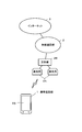
- FIG. 1 is a block diagram showing a communication network system in which a mobile phone applied as a terminal device can be used.
- the mobile phone 1 is, for example, a multi-function mobile phone called a smart phone, and includes a call function, a touch input function, an e-mail function, an Internet connection function (Web access function), and the like as its basic functions.
- a touch screen TD is disposed over substantially the entire area.
- the cellular phone 1 When the cellular phone 1 is connected to the wireless communication network (mobile communication network) 2 from the nearest base station 2A and exchange 2B, the cellular phone 1 is connected to other cellular phones (not shown) via the wireless communication network 2.
- the wireless communication network mobile communication network
- the mobile phone When a call can be made and the mobile phone is connected to the Internet 3 via the wireless communication network 2, the user can access and browse the Web site.
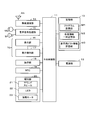
- FIG. 2 is a block diagram showing basic components of the mobile phone 1.
- the central control unit 11 operates by supplying power from a power supply unit 12 including a secondary battery, and controls the overall operation of the mobile phone 1 according to various programs in the storage unit 13 and a memory.
- the storage unit 13 includes a program storage unit M1, various information temporary storage units M2, a display pictogram information storage unit M3, and the like.
- the program storage unit M1 stores programs and various applications for realizing the present embodiment in accordance with the operation procedures shown in FIGS. 5 to 9, and stores information necessary for the programs. Yes.
- the storage unit 13 may be configured to include a removable portable memory (external recording medium) such as an SD card or an IC card, and includes a storage area on a predetermined external server (not shown). It may be a thing.
- the various information temporary storage unit M2 is a work area that temporarily stores various information necessary for the operation of the mobile phone 1, such as flag information and screen information.
- the display pictogram information storage unit M3 will be
- the wireless communication unit 14 transmits / receives data to / from the nearest base station 2A during operation of the call function, e-mail function, Internet connection function, etc., and from the receiving side of the baseband unit during operation of the call function.
- the central control unit 11 When the signal is taken in, demodulated into a received baseband signal and output to the central control unit 11, the central control unit 11 outputs the audio from the call speaker SP via the audio signal processing unit 15, and the call microphone.
- the input voice data from the MC is taken from the voice signal processing unit 15 and encoded into a transmission baseband signal, which is then given to the transmission side of the baseband unit and transmitted from the antenna AN.
- the display unit 16 uses high-definition liquid crystal or organic EL, and displays various information such as character information, a standby image, a pictogram for display (Pictogram: pictogram, etc.), a function icon, and the like.
- a touch screen TD is configured by laminating a display operation unit 17 including a transparent contact sensor that detects contact of an object such as a finger or an instrument on the surface of the panel.
- the display operation unit 17 detects an operation on the display unit 16.
- a contact operation (touch operation) on the display unit 16 is performed, the display operation unit 17 detects a touch on the display unit 16 as a touch operation, and detects the detection. The result is given to the central control unit 11.
- the display operation unit 17 is not limited to the contact detection by the contact sensor, but can also detect the operation tool and the pushing (pressing) of the finger.
- the central control unit 11 receives the operation input signal from the display operation unit 17. The presence / absence of a touch operation or a pressing operation is detected based on this, or the operation position (touch position) is detected.
- the entire display unit 16 is not limited to the touch screen TD, and a part of the display unit 16 may be the touch screen TD.
- the display operation unit 17 is not limited to a transparent contact sensor, and may include a non-contact sensor that detects the movement of an object existing at a short distance due to capacitance or the like.
- the operation unit 18 has various push button type keys such as a power button, and the central control unit 11 executes processing according to an input operation signal.
- the RTC (real time clock module) 19 constitutes a clock unit, and the central control unit 11 acquires the current date and time from the RTC 19.
- the notification unit 20 includes a sound speaker 21, an LED (light emitting diode) 22, and a vibration motor 23. The notification unit 20 is driven when an incoming call is received to notify an incoming call, and is also driven when an alarm is notified.
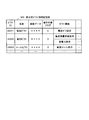
- FIG. 3 is a diagram for explaining the display pictogram information storage unit M3.
- the display pictogram information storage unit M3 stores information about pictograms for display displayed in the display unit 16 for each pictogram.
- the “pictogram ID”, “name”, “image data”, “operation target flag” , “Pict function”,... “Pict ID” and “Name” are information for identifying a pict
- “Image data” is actual data (image data) of a pictograph such as a pictograph.
- the “operation target flag” is a flag indicating whether or not an operation for the display pictogram has been performed in order to execute a function corresponding to the display pictogram
- “1” is an operation for the display pictogram. It is shown that.
- Pict function is “Radio wave off setting to block radio wave” if “Name” is radio wave pict, “Battery remaining detail display” and “Power saving setting to suppress power consumption”, e-mail if battery name is pictograph If it is a pictograph, “new mail display”,... Are stored as a pictograph function.
- FIG. 4 is a diagram for explaining a lock screen that prevents an erroneous operation on the display unit 16.
- the lock screen LK for preventing erroneous operation displayed on the display unit 16 has a display area (first display area) LK1 for display pictograms and a display area (second display area) LK2 for unlock icons. .
- the lock screen LK is unlocked by performing an operation of moving the unlock icon (black triangle mark in the figure) to a specific position (end mark: black square mark display position in the figure). In this case, it has a release position display area (third display area) LK3 for displaying the unlock position, and another main (main) display area (fourth display area) LK4.
- image data such as wallpaper may be displayed on the fourth display area LK4 on the lock screen LK
- the display layout on the lock screen LK is not limited to the illustrated example, and may be arbitrary.
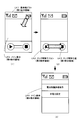
- FIG. 10 is a diagram illustrating a case where a predetermined operation other than the unlocking operation is a display picto function execution operation and a function corresponding to the display picto is executed.
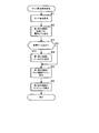
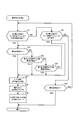
- FIG. 5 is a flowchart (main flow) showing an operation that is started when a transition to the lock screen that prevents an erroneous operation on the display unit 16 is instructed. When the flow of FIG. Returns to the main flow (not shown) of the overall operation.
- the central control unit 11 performs a lock screen display process for displaying a lock screen on the display unit 16 in response to an instruction to transition to the lock screen (step A1).
- the instruction for transition to the lock screen is not limited to a manual instruction, but may be an automatic instruction.
- FIG. 6 is a flowchart for explaining the lock screen display process (step A1 in FIG. 5) in detail.
- the central control unit 11 displays the lock screen LK on the display unit 16 (step B1 in FIG. 6), and then displays the radio wave pictograph and the battery pictograph in the first display area LK1, which is the display area of the display pictograph. (Step B2).
- it is checked whether a new mail has been received (step B3). If it has been received (YES in step B3), a mail picture is displayed in the first display area LK1 (step B4).
- an unlock icon black triangle mark in FIG.
- step B6 is displayed in the second display area LK2, which is a display area for the unlock icon (step B5), and a third display area for the unlock position is displayed.
- An end mark (black square mark in FIG. 4) is displayed in the display area LK3 (step B6).
- step A1 in FIG. 5 When the lock screen display process (step A1 in FIG. 5) is finished, it is checked whether the unlock icon in the second display area LK2 is detected (step A2), or in the first display area LK1. It is checked whether it is detected that the display pictograph is operated (step A3). Now, when an operation on the unlock icon is detected (YES in step A2), the operation detection process A for determining what operation has been performed since the start of the operation on the unlock icon. The process proceeds to execution (step A4). Further, when an operation on the display pictogram is detected (YES in step A3), an operation detection process B for determining what operation has been performed since that time. Execution proceeds (step A5).
- FIG. 7 is a flowchart for explaining the operation detection process A (step A4 in FIG. 5) in detail.
- the central control unit 11 checks what operation has been performed as the next operation (steps C1 to C4). That is, it is checked whether a movement operation (slide operation) up to the third display area LK3 is detected (step C1), or whether a movement operation up to any display pictogram in the first display area LK1 is detected. (Step C2), it is checked whether an operation (predetermined operation other than the movement operation) on any of the display pictograms in the first display area LK1 is detected (step C3).
- step C4 the process proceeds to the next step C4 to check whether the operation release to the unlock icon is detected, and the operation release is also detected. If not (NO in step C4), the process returns to step C1 described above. However, when operation release to the unlock icon is detected (YES in step C4), the operation of FIG. Get out of the flow.
- a movement operation sliding operation for moving the unlock icon to the third display area LK3 is detected after the unlock icon is operated (YES in step C1)
- the inside of the third display area LK3 is detected. Wait until the operation at is released (step C5).
- Step C5 the flow of FIG.
- step C10 an operation for instructing the execution of the picto function has been performed (step C10), and the type of the operated display pict is determined (step C11). For example, as shown in FIG. 10 (1), an operation (for example, a single touch operation) on an unlock icon in the second display area LK2 and an operation (for example, a single radio wave pictograph in the first display area LK1). If the touch operation is performed at the same time or after a certain amount of time, it is determined that an operation instructing execution of the radio wave pict function has been performed. Then, the “operation target flag” in the display pictogram information storage unit M3 corresponding to the display pictogram is set to “1” (step C12). Thereafter, the flow of FIG.
- Step C2 when a movement operation (slide operation) for moving the unlock icon to any of the display picts in the first display area LK1 is detected after the unlock icon is operated (YES in step C2). Whether or not the release of the operation is detected at the position of the display pictogram (step C7), or whether the movement operation from the first display area LK1 to the fourth display area LK4 which is the main display area is detected. (Step C8), it is checked whether a movement operation from the first display area LK1 to the third display area LK3 has been detected (step C9).
- step C10 If the release of the operation is detected at any of the display pictogram positions (YES in step C7), it is determined that an operation instructing execution of the pictogram function has been performed (step C10).
- the type of the displayed picture is determined (step C11). For example, as shown in FIG. 10 (2), when a movement operation is performed up to the radio wave pict within the first display area LK1 after the unlock icon in the second display area LK2 is touched, the radio wave pictograph is displayed. It is determined that an operation for instructing execution of the function has been performed.
- step C2 After detecting a movement operation to any display pict within the first display area LK1 (YES in Step C2), when a movement operation from the first display area LK1 to the fourth display area LK4 is further detected. In addition (YES in step C8), it is determined that an operation for instructing execution of the picto function is performed (step C10), and the type of the operated display pict is determined (step C11). Similarly, after detecting a movement operation to any display pict within the first display area LK1 (YES in step C2), a movement operation from the first display area LK1 to the third display area LK3 is further detected. Sometimes (YES in step C9), it is determined that an operation for instructing execution of the picto function is performed (step C10), and the type of the operated display pict is determined (step C11).
- FIG. 8 is a flowchart for explaining the operation detection process B (step A5 in FIG. 5) in detail.
- the central control unit 11 checks whether a movement operation to the unlock icon in the second display area LK2 is detected after an operation on the display pictogram is performed (step D1), or the second display area. It is checked whether an operation on the unlock icon in LK2 (a predetermined operation other than the movement operation) has been detected (step D2). Here, if none of the above-described operations is detected (NO in steps D1 and D2), it is checked whether the operation release to the display pictogram has been detected (step D3).
- step D3 If the operation release to the display pictogram is not detected (NO in step D3), the process returns to the above-described step D1, but when the operation release is detected (YES in step D3), the flow of FIG.
- step D4 when an operation for moving the display pictograph to the unlock icon in the second display area LK2 is detected after the display pictograph has been operated (YES in step D1), the position of the unlock icon is displayed. It is checked whether the operation cancellation is detected (step D4), whether a movement operation from the second display area LK2 to the fourth display area LK4 as the main display area is detected (step D5), or the second display. It is checked whether or not a movement operation from the area LK2 to the third display area LK3 has been detected (step D6).
- step D4 If an operation release in the second display area LK2 is detected (YES in step D4), it is determined that an operation instructing execution of the picto function is performed (step D7), and the operated display The type of pictograph for use is discriminated (step D8). In addition, after detecting the movement operation up to the unlock icon (YES in step D1) and also when the movement operation up to the fourth display area LK4 is detected (YES in step D5), the execution of the pictogram function is instructed. It is determined that the operation to be performed has been performed (step D7), and the type of the operated display picture is determined (step D8).
- step D1 After detecting the movement operation up to the unlock icon (YES in step D1), when the movement operation up to the third display area LK3 is further detected (YES in step D6), the pictogram function is executed. It is determined that the instructing operation has been performed (step D7), and the type of the operated display picture is determined (step D8). Then, after the “operation target flag” in the display pictogram information storage unit M3 corresponding to the display pictogram is set to “1” (step D9), the flow of FIG. 8 is exited.
- step A6 A7 the determination result in the operation detection process A or the operation detection process B described above is examined (step A6, A7). That is, it is checked whether it is determined that the unlocking operation has been performed (step A6) or whether it has been determined that the operation instructing execution of the pictogram function has been performed (step A7).
- a lock release operation is performed (YES in step A6), a predetermined screen (eg, home screen, menu screen, etc.) is displayed to release the lock screen (step A8), but the pictogram function is executed.
- step A7 a pictogram function execution process (step A9) described later is performed, and then the process proceeds to step A8 to display a predetermined screen.
- step A7 if it is not determined that the unlocking operation and the pictogram function executing operation have been performed (NO in step A7), the process returns to the first step A1. Note that after the pictogram function execution processing, the lock screen may not be released, and the first step A1 may be returned to maintain the lock screen.
- FIG. 9 is a flowchart for explaining the pictogram function execution process (step A9 in FIG. 5) in detail.
- the central control unit 11 reads the display pictograph whose “operation object flag” is “1” with reference to the display pict information storage unit M3 (step E1), and displays the corresponding pict function screen (step E1).
- Step E2 For example, a radio wave off setting screen, a battery remaining amount detailed display / power saving setting selection menu screen, a new mail display screen, and the like are displayed as a pictograph function screen.
- FIG. 10 (3) shows a radio wave off setting screen displayed in response to the operation of FIG. 10 (1) or (2).
- step E3 In the state where the pictogram function screen is displayed in this way, it is investigated whether various operations of the pictogram function have been detected (step E3), or whether the picto end operation has been detected (step E4).
- step E4 when an on / off setting operation, a selection menu selection operation, a new mail scrolling operation, or the like is detected as an operation corresponding to the displayed pict function screen (YES in step E3), the operation is performed accordingly.
- step E5 After executing the pict function (step E5), the process returns to the above-described step E2.
- the radio wave off setting screen as shown in FIG. 10 (3), when a check mark is put in either of the items "turn off radio wave” or "do not turn off radio wave” by user operation, the corresponding Perform pictogram function.
- step E4 When a pict end operation is detected (YES in step E4), the pict function is terminated (step E6). Then, the “operation target flag” corresponding to the display picture is set to “0” (step E7). Thereafter, the flow of FIG. 9 is exited.
- the central control unit 11 in the first embodiment displays the display pictograph in the first display area in the lock screen for preventing an erroneous operation on the display unit 16 and also displays the second display area.
- the display pictogram function execution operation When an operation on the display unit 6 other than the unlocking operation is detected while the unlock icon is displayed, it is determined that the display pictogram function execution operation has been performed, and the display pictogram is handled. Since the function is executed, the function corresponding to the display pictograph can be easily executed without releasing the lock screen, and even the user can perform the display with a predetermined operation other than the unlocking operation. The function corresponding to the pictograph can be executed, and it is rich in operability and convenience.
- the display picto function execution operation is performed. Therefore, the user can easily execute the function corresponding to the display pictogram simply by moving the unlock icon to the display pictogram. Further, since the operation is for the unlock icon, the possibility of an erroneous operation is not increased. Further, since the operation is for the display pictogram, the function corresponding to the display pictogram can be executed by an intuitive operation.
- an operation for moving from the second display area LK2 to the first display area LK1 is detected, and further, no operation on the unlock icon is detected.
- the operation is a display picto function execution operation
- the user performs an operation to move from the second display area to the first display area after performing an operation on the unlock icon
- the function corresponding to the display pictogram displayed on the lock screen can be easily executed by stopping the operation on the unlock icon.
- the operation is for the unlock icon, the possibility of an erroneous operation is not increased.
- the function corresponding to the display pictogram can be executed by an intuitive operation.
- an operation for moving from the second display area LK2 to the first display area LK1 is detected, and further up to the fourth display area LK4 which is the main display area.
- the operation is a display picto function execution operation. Therefore, for the user, the operation is performed from the second display area LK2 via the first display area LK1 through the movement operation path. It can be instructed to display the pictogram function screen in the fourth display area LK4. Further, since the operation is for the unlock icon, the possibility of an erroneous operation is not increased. Further, since the operation is for the display pictogram, the function corresponding to the display pictogram can be executed by an intuitive operation.
- an operation to move from the second display area LK2 to the first display area LK1 is detected, and further an operation to move to the third display area LK3 is detected.
- the operation since it is determined that the operation is a display pictogram function execution operation, the user may set an operation obtained by adding an operation via the display pictogram to the unlocking operation as a display pictogram function execution operation. This is an easy-to-understand operation for the user. Further, since the operation is for the unlock icon, the possibility of an erroneous operation is not increased. Further, since the operation is for the display pictogram, the function corresponding to the display pictogram can be executed by an intuitive operation.
- an operation for moving from the first display area LK1 to the second display area LK2 is detected, and further no operation on the display pictogram is detected.
- the operation is a display picto function execution operation
- the user performs an operation to move from the first display area to the second display area after performing an operation on the display picto.
- the function corresponding to the display pictogram displayed on the lock screen can be easily executed by stopping the operation on the unlock icon. Further, since the operation is for the unlock icon, the possibility of an erroneous operation is not increased. Further, since the operation is for the display pictogram, the function corresponding to the display pictogram can be executed by an intuitive operation.
- an operation of moving from the first display area LK1 to the second display area LK2 is detected, and further up to the fourth display area LK4 which is the main display area.
- the operation is a display picto function execution operation. Therefore, after the user performs an operation on the display picto, the first display area LK1 to the second display area.
- the function corresponding to the display pictogram displayed on the lock screen can be easily executed. Further, since the operation is for the unlock icon, the possibility of an erroneous operation is not increased. Further, since the operation is for the display pictogram, the function corresponding to the display pictogram can be executed by an intuitive operation.
- an operation for moving from the first display area LK1 to the second display area LK2 is detected, and further an operation for moving to the third display area LK3 is detected.
- the operation is a display picto function execution operation
- the user moves the first display area LK1 to the second display area LK2 after performing an operation on the display pictogram.
- the function corresponding to the display pictogram displayed on the lock screen can be easily executed.
- it is an operation to the unlock icon the possibility of erroneous operation is not increased.
- the operation is for the display pictogram, the function corresponding to the display pictogram can be executed by an intuitive operation.
- a function corresponding to the display pictogram operated from among the plurality of display pictograms is executed.
- the function corresponding to the display pictogram can be easily executed by operating the display pictogram corresponding to the function to be executed.
- a predetermined operation other than the unlocking operation is a display pictogram function execution operation.
- a predetermined operation is not performed in the unlocking operation.
- the operation to which the above operation is added is determined to be the display pictogram function execution operation.
- the same or the same names are denoted by the same reference numerals, the description thereof will be omitted, and the following description will focus on the features of the second embodiment. .
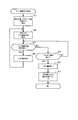
- FIG. 11 is a flowchart (main flow) illustrating an operation that is started when a transition to the lock screen that prevents an erroneous operation on the display unit 16 is instructed in the second embodiment.
- FIG. 12 is a diagram exemplifying a case where an operation obtained by adding a predetermined operation to the unlocking operation is a display pictogram function execution operation, and a function corresponding to the display pictogram is executed, and the display of the first display area LK1 is illustrated. If the unlocking operation is performed within a predetermined time after the operation for the display pict is performed, the function corresponding to the display pict is executed.
- step F1 when the central control unit 11 is instructed to transition to the lock screen, the central control unit 11 performs a lock screen display process for displaying the lock screen on the display unit 16 (step F1). Since this lock screen display process is executed according to the flow of FIG. 6 described above, the description thereof will be omitted.
- step F2 When the lock screen display process is finished, it is checked whether an operation to the unlock icon in the second display area LK2 is detected (step F2), or an operation to the display pictograph in the first display area LK1 is detected. (Step F3).
- step F4 the process waits until a movement operation (slide operation) for moving the unlock icon to the third display area LK3 is detected (step F4).
- a movement operation up to the third display area LK3 is detected (YES in step F4)
- the operation is released YES in step F5)
- it is determined that a predetermined unlocking operation has been performed step F6).
- step F7 Since the timer is not operating now (NO in step F7), a predetermined time is required to release the lock screen.
- the display is switched to a screen (for example, a home screen, a menu screen, etc.) (step F10).
- step F3 when an operation on any of the display pictograms in the first display area LK1 is detected (YES in step F3), it is checked whether an operation release is detected at the position of the display pictogram (step F11). It is checked whether or not a movement operation for moving to the fourth display area LK4 of the main display area has been detected (step F12).
- FIG. 12 (1) shows a case where an operation for moving the battery pict to the fourth display area LK4 of the main display area is performed after an operation is performed on the battery pict in the first display area LK1.
- step F11 when an operation release in the display pictogram is detected (YES in step F11) or a movement operation up to the fourth display area LK4 is detected (YES in step F12), execution of the pictogram function is instructed. It is determined that the operation has been performed (step F13), and the type of the operated display picture is determined (step F14). Then, the “operation target flag” in the display pictogram information storage unit M3 corresponding to the display pictogram is set to “1” (step F15). Thereafter, an initial value (for example, 5 seconds) is set in the countdown timer, and a measurement operation for subtracting the value is started (step F16). The countdown timer measures the time from when the picto function execution operation is performed to when the lock release operation is performed. After the measurement operation is started, the process returns to step F2.
- FIG. 12 (2) shows the unlock operation after the picto function execution operation, and shows the case where the unlock operation is performed within a predetermined time (for example, 5 seconds) after the picto function execution operation is performed. ing.
- the countdown timer is operating (YES in step F7). Therefore, after the countdown timer measurement operation is stopped (step F8), the above-described FIG.
- the pictogram function execution process (step F9) is performed in accordance with the flow.
- FIG. 12 (3) shows an unlocking operation as shown in FIG. 12 (2) within a predetermined time after detecting an operation on the display pictogram in the first display area LK1 as shown in FIG. 12 (1).
- a screen corresponding to a battery pict (detailed battery remaining amount display and power saving setting screen) is displayed as a display pict corresponding screen. Note that after the pictogram function execution process, the lock screen may not be released, and the first step F1 may be returned to maintain the lock screen.
- the central control unit 11 detects the display when the unlocking operation is performed within a predetermined time after detecting the operation to the display pictogram in the first display area LK1. Since it is determined that the operation is a pictogram function execution operation, the user performs an unlock operation within a predetermined time after performing an operation on the display pictogram of the first display area LK1, thereby displaying the lock screen.
- the function corresponding to the displayed display pictograph can be easily executed.
- the unlocking operation is performed before the display pictogram function is executed, the possibility of an erroneous operation does not increase. Further, since the operation is for the display pictogram, the user can execute the function corresponding to the display pictogram by an intuitive operation.
- the user notices that the screen is a lock screen by not executing the display pictogram function. If the unlocking operation is performed within a predetermined time, the display pictogram function is executed. Therefore, after performing the unlocking operation, the user does not feel bothered to perform the display pictogram function executing operation again. Has a special effect.
- the unlocking operation is performed within a predetermined time.
- the operation is a display picto function execution operation
- the user operates the display picto and performs an operation of moving from the first display area LK1 to the second display area LK2.
- the function corresponding to the display pictogram displayed on the lock screen can be easily executed.
- the unlocking operation is performed before the display pictogram function is executed, the possibility of an erroneous operation does not increase.
- the operation is for the display pictogram
- the user can execute a function corresponding to the display pictogram by an intuitive operation.
- the user performs an operation on the display pictogram in the first display area LK1 and moves from the first display area LK1 to the second display area LK2.
- the pictographic function for display will be executed.
- the function corresponding to the display pictogram operated from among the plurality of display pictograms is executed.
- the function corresponding to the display pictogram can be easily executed by operating the display pictogram corresponding to the function to be executed.
- radio wave pictograms, battery pictograms, and mail pictograms are illustrated as display pictograms, but the present invention is not limited thereto and is arbitrary.
- the function corresponding to the display pictograph is also arbitrary. For example, as long as it is a function corresponding to the radio wave pictograph, it may be an arbitrary function related to the display pictograph such as a call time display function.
- the display unit 16 is a display unit provided in the terminal device, but may be an arbitrary external display device such as an external monitor.
- a PC personal computer
- a digital camera a digital camera
- a PDA personal portable information communication device
- a tablet terminal device a mobile phone other than a smartphone It may be an electronic game, a music player, or the like.
- each of the above-described embodiments may be separated into a plurality of cases by function, and are not limited to a single case.
- each step described in the above-described flowchart is not limited to time-series processing, and a plurality of steps may be processed in parallel or separately.
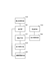
- FIG. 13 is a block diagram (functional block diagram) of Appendix 1.
- the invention described in Appendix 1 is Detection means 101 (display operation unit 17, central control unit 11, storage unit 13 in FIG. 2) that detects an operation on the display unit (display unit 16 in FIG. 2) and an operation detected by the detection unit 101
- a terminal device (mobile phone 1 in FIG. 1) provided with processing means 102 (in FIG. 2, the central control unit 11 and the storage unit 13),
- Display control means 103 (a central control unit in FIG. 1) displays a display pictograph in a first display area in a lock screen for preventing erroneous operation of the display unit 100 and displays a lock release icon in a second display area.
- First discriminating means 104 (in FIG. 2, the central control unit 11 and the storage unit 13) for discriminating that the unlocking operation has been performed;
- a screen transition means 105 (the central control section 11 and the storage section 13 in FIG. 2) that transitions from a lock screen to a predetermined screen when it is determined by the first determination means 104 that an unlock operation has been performed;
- a second determination unit 106 (in FIG.
- the processing means 102 executes a function corresponding to the display pictogram displayed in the first display area when the second discriminating means 106 determines that the operation is a display pictogram function execution operation.
- a terminal device characterized by being configured as described above.
- the second determining means determines that the operation is a display picto function execution operation when an operation other than the unlocking operation and a predetermined operation on the unlock icon is detected by the detecting means;
- the second discriminating unit performs a display picto function execution operation when the detection unit detects an operation on the unlock icon in the second display area and an operation on the display pict in the first display area. It is determined that The terminal device according to claim 2, which is configured as described above.
- the second discriminating unit detects a movement from the second display region to the first display region after an operation to the unlock icon in the second display region is detected by the detecting unit. It is determined that the display picto function execution operation is performed.
- the second determining means detects an operation of moving from the second display area to the first display area after the detection means detects an operation on the unlock icon in the second display area. When the operation on the unlock icon is no longer detected, it is determined that the display picto function execution operation is performed.
- the second discriminating unit detects an operation of moving from the first display region to the fourth display region after an operation to the display pictogram in the first display region is detected by the detecting unit, If it is determined that the unlocking operation is performed by the first determining means within the time, it is determined that the display picto function execution operation is performed;
- an operation for moving the unlock icon from the second display area to the third display area is detected after an operation on the unlock icon in the second display area is detected, the unlock operation is performed.
- the processing method characterized by including.
- the second determining means detects an operation of moving from the second display area to the first display area after the detection means detects an operation on the unlock icon in the second display area.
- an operation of moving to the fourth display area which is the main display area, is detected, it is determined that the display picto function execution operation is performed.
- the second discriminating unit detects an operation of moving from the second display region to the war record first display region after the detection unit detects an operation to the unlock icon in the second display region, When an operation to move to the third display area is detected, it is determined that the display picto function execution operation is performed.
- the second discriminating unit detects an operation of moving from the first display region to the second display region after the detection unit detects an operation to the display pictogram in the first display region. When an operation on the display pictograph is no longer detected, it is determined that the display pict function execution operation is performed.
- the second discriminating unit detects an operation of moving from the first display region to the second display region after the detection unit detects an operation to the display pictogram in the first display region.
- an operation of moving to the fourth display area which is the main display area, it is determined that the display picto function execution operation is performed.
- the second discriminating unit detects an operation of moving from the first display region to the second display region after the detection unit detects an operation on the display pictogram in the first display region. Further, when an operation of moving to the third display area is detected, it is determined that the operation is a display picto function execution operation.
- the display control means displays a plurality of display pictograms in the first display area, And further comprising a third discriminating unit for discriminating a display pictogram whose operation is detected by the detecting unit from among the plurality of display pictograms displayed by the display control unit,
- the processing means executes a function corresponding to the display pictograph determined by the third determining means.
Abstract
Description
例えば、従来、表示部への操作を検出する手段の例として、タッチパネルを利用した電子デバイスにおいて、ロック画面に表示されているロック解除アイコンを特定の位置まで移動させる操作によってロック解除を行うようにした技術が開示されている(特許文献1参照)。 In such a terminal device such as a mobile phone that detects an operation performed on the display unit and executes various processes according to the operation, an erroneous operation on the display unit (such as an inadvertent operation). In some cases, a screen (lock screen) that suppresses acceptance of the operation is displayed. There are various operations for transitioning from this lock screen to another screen (that is, operations for unlocking), and one of them is to specify the unlock icon displayed on the lock screen. There is an operation to move to the position.
For example, conventionally, as an example of means for detecting an operation on a display unit, in an electronic device using a touch panel, unlocking is performed by an operation of moving an unlock icon displayed on a lock screen to a specific position. Has been disclosed (see Patent Document 1).
表示部への操作を検出する検出手段と、前記検出手段によって検出された操作に応じた処理を実行する処理手段とを備えた端末装置であって、
前記表示部への誤操作を防止するためのロック画面内の第1表示領域に表示用ピクトを表示させ、第2表示領域にロック解除アイコンを表示させる表示制御手段と、
前記検出手段によって前記第2表示領域内のロック解除アイコンへの操作が検出された後、そのロック解除用アイコンを第2表示領域から第3表示領域へ移動させる操作が検出された場合に、ロック解除操作が行われたと判別する第1判別手段と、
前記第1判別手段によりロック解除操作が行われたと判別された場合に、ロック画面から所定の画面に遷移させる画面遷移手段と、
前記検出手段によってロック解除操作以外の表示部への所定の操作が検出された場合に、表示用ピクト機能実行操作であると判別する第2判別手段と、
を備え、前記処理手段は、前記第2判別手段によって表示用ピクト機能実行操作であると判別された場合に、前記第1表示領域に表示される表示用ピクトに対応する機能を実行する、
ようにしたことを特徴とする端末装置である。 In order to solve the above-described problems, the terminal device of the present invention
A terminal device comprising: a detecting unit that detects an operation on the display unit; and a processing unit that executes a process according to the operation detected by the detecting unit,
Display control means for displaying a display pictograph in a first display area in a lock screen for preventing an erroneous operation on the display unit, and displaying an unlock icon in a second display area;
The lock is detected when an operation to move the unlock icon from the second display area to the third display area is detected after the detection means detects an operation to the unlock icon in the second display area. First determination means for determining that a release operation has been performed;
Screen transition means for transitioning from a lock screen to a predetermined screen when it is determined by the first determination means that an unlock operation has been performed;
Second determination means for determining that the operation is a display picto function execution operation when a predetermined operation on the display unit other than the unlocking operation is detected by the detection means;
And the processing means executes a function corresponding to the display pictogram displayed in the first display area when the second discriminating means discriminates that it is a display pictogram function execution operation.
This is a terminal device that is characterized as described above.
表示部への誤操作を防止するためのロック画面内の第1表示領域に表示用ピクトを表示させ、第2表示領域にロック解除アイコンを表示させる表示制御ステップと、
前記第2表示領域内のロック解除アイコンへの操作が検出された後、そのロック解除用アイコンを第2表示領域から第3表示領域へ移動させる操作が検出された場合に、ロック解除操作が行われたと判別する第1判別ステップと、
前記ロック解除操作が行われたと判別された場合に、ロック画面から所定の画面に遷移させる画面遷移ステップと、
前記ロック解除操作以外の表示部への所定の操作が検出された場合に、表示用ピクト機能実行操作であると判別する第2判別ステップと、
前記表示用ピクト機能実行操作であると判別された場合に、前記第1表示領域に表示される表示用ピクトに対応する機能を実行する処理ステップと、
を含むことを特徴とする処理方法である。 In order to solve the above-described problems, the processing method of the present invention includes:
A display control step of displaying a display pictograph in the first display area in the lock screen for preventing an erroneous operation on the display unit and displaying an unlock icon in the second display area;
When an operation for moving the unlock icon from the second display area to the third display area is detected after an operation on the unlock icon in the second display area is detected, the unlock operation is performed. A first discriminating step for discriminating that it has been broken;
A screen transition step for transitioning from a lock screen to a predetermined screen when it is determined that the unlocking operation has been performed;
A second determination step of determining that the operation is a display picto function execution operation when a predetermined operation on the display unit other than the unlocking operation is detected;
A processing step of executing a function corresponding to the display pictogram displayed in the first display area when it is determined that the display picto function execution operation is performed;
The processing method characterized by including.
コンピュータに対して、
表示部への誤操作を防止するためのロック画面内の第1表示領域に表示用ピクトを表示させ、第2表示領域にロック解除アイコンを表示させる表示制御機能と、
前記第2表示領域内のロック解除アイコンへの操作が検出された後、そのロック解除用アイコンを第2表示領域から第3表示領域へ移動させる操作が検出された場合に、ロック解除操作が行われたと判別する第1判別機能と、
前記ロック解除操作が行われたと判別された場合に、ロック画面から所定の画面に遷移させる画面遷移機能と、
前記ロック解除操作以外の表示部への所定の操作が検出された場合に、表示用ピクト機能実行操作であると判別する第2判別機能と、
前記表示用ピクト機能実行操作であると判別された場合に、前記第1表示領域に表示される表示用ピクトに対応する機能を実行する処理機能と、
を実現させるためのプログラムである。 In order to solve the above-described problems, the program of the present invention
Against the computer,
A display control function for displaying a display pictograph in a first display area in a lock screen and preventing a lock release icon from being displayed in a second display area to prevent an erroneous operation on the display unit;
When an operation to move the unlock icon from the second display area to the third display area is detected after an operation to the unlock icon in the second display area is detected, the unlock operation is performed. A first discriminating function for discriminating that
A screen transition function for transitioning from a lock screen to a predetermined screen when it is determined that the unlocking operation has been performed;
A second discriminating function that discriminates a display picto function execution operation when a predetermined operation on the display unit other than the unlocking operation is detected;
A processing function for executing a function corresponding to the display pictogram displayed in the first display area when it is determined that the display picto function execution operation is performed;
It is a program for realizing.
(第1実施形態)
先ず、図1~図10を参照して本発明の第1実施形態を説明する。
図1は、端末装置として適用した携帯電話機が利用可能な通信ネットワークシステムを示したブロック図である。
携帯電話機1は、例えば、スマートフォンと呼ばれる多機能型携帯電話機であり、その基本機能として通話機能、タッチ入力機能、電子メール機能、インターネット接続機能(Webアクセス機能)などを備え、その筐体の前面略全域にはタッチスクリーンTDが配設されている。携帯電話機1は、最寄りの基地局2A、交換機2Bから無線通信網(移動体通信網)2に接続されると、この無線通信網2を介して他の携帯電話機(図示省略)との間で通話可能な状態となり、また、無線通信網2を介してインターネット3に接続されると、Webサイトをアクセスして閲覧可能となる。 Hereinafter, embodiments of the present invention will be described in detail with reference to the drawings.
(First embodiment)
First, a first embodiment of the present invention will be described with reference to FIGS.
FIG. 1 is a block diagram showing a communication network system in which a mobile phone applied as a terminal device can be used.
The
中央制御部11は、二次電池を備えた電源部12からの電力供給によって動作し、記憶部13内の各種のプログラムに応じてこの携帯電話機1の全体動作を制御する中央演算処理装置やメモリ(図示省略)などを有している。この記憶部13には、プログラム記憶部M1、各種情報一時記憶部M2、表示用ピクト情報記憶部M3などが設けられている。プログラム記憶部M1は、図5~図9に示した動作手順に応じて本実施形態を実現するためのプログラムや各種のアプリケーションなどが格納されているほか、それに必要とする情報などが記憶されている。なお、記憶部13は、例えば、SDカード、ICカードなど、着脱自在な可搬型メモリ(外部記録メディア)を含む構成であってもよく、また、図示しない所定の外部サーバ上の記憶領域を含むものであってもよい。また、各種情報一時記憶部M2は、フラグ情報、画面情報など、携帯電話機1が動作するために必要な各種の情報を一時的に記憶するワーク領域である。なお、表示用ピクト情報記憶部M3については、後で詳述するものとする。 FIG. 2 is a block diagram showing basic components of the
The
表示用ピクト情報記憶部M3は、表示部16内に表示される表示用ピクトに関する情報をピクト毎に記憶するもので、「ピクトID」、「名称」、「画像データ」、「操作対象フラグ」、「ピクト機能」、…の各項目を有する構成となっている。「ピクトID」、「名称」は、ピクトを識別する情報であり、「画像データ」は、絵文字などのピクトの実データ(画像データ)である。「操作対象フラグ」は、表示用ピクトに対応する機能を実行させるために表示用ピクトに対する操作が行われたか否かを示すフラグであり、“1”は、表示用ピクトに対する操作が行われたことを示している。「ピクト機能」は、「名称」が電波ピクトであれば“電波を遮断する電波オフ設定”、電池ピクトであれば“電池残量詳細表示”及び“電力消費を抑制する省電力設定”、メールピクトであれば“新着メール表示”、…がピクト機能として記憶されている。 FIG. 3 is a diagram for explaining the display pictogram information storage unit M3.
The display pictogram information storage unit M3 stores information about pictograms for display displayed in the
表示部16に表示される誤操作防止用のロック画面LKには、表示用ピクトの表示領域(第1表示領域)LK1と、ロック解除アイコンの表示領域(第2表示領域)LK2を有している。更にロック画面LKには、ロック解除アイコン(図中、黒塗り三角マーク)を特定の位置(エンドマーク:図中、黒塗り四角マークの表示位置)まで移動させる操作を行うことによってロックを解除する場合に、そのロック解除位置を表示する解除位置表示領域(第3表示領域)LK3と、その他の主要(メイン)表示領域(第4表示領域)LK4を有している。なお、ロック画面LKでは壁紙などの画像データを第4表示領域LK4に表示させるようにしてもよく、また、ロック画面LKでの表示レイアウトも図示の例に限らず、任意であってもよい。 FIG. 4 is a diagram for explaining a lock screen that prevents an erroneous operation on the
The lock screen LK for preventing erroneous operation displayed on the
図5は、表示部16への誤操作を防止するロック画面への遷移が指示された際に実行開始される動作を示したフローチャート(メインフロー)であり、この図5のフローから抜けた際には、全体動作のメインフロー(図示省略)に戻る。先ず、中央制御部11は、ロック画面への遷移の指示に応答して表示部16にロック画面を表示させるロック画面表示処理を行う(ステップA1)。なお、ロック画面への遷移の指示は、手動的な指示に限らず、自動的な指示であってもよい。 Next, the operation concept of the mobile phone in the first embodiment will be described with reference to the flowcharts shown in FIGS. Here, each function described in these flowcharts is stored in the form of a readable program code, and operations according to the program code are sequentially executed. FIG. 10 is a diagram illustrating a case where a predetermined operation other than the unlocking operation is a display picto function execution operation and a function corresponding to the display picto is executed.
FIG. 5 is a flowchart (main flow) showing an operation that is started when a transition to the lock screen that prevents an erroneous operation on the
先ず、中央制御部11は、表示部16にロック画面LKを表示(図6のステップB1)させた後、表示用ピクトの表示領域である第1表示領域LK1内に電波ピクト及び電池ピクトを表示させる(ステップB2)。そして、新着メールを受信しているかを調べ(ステップB3)、受信していれば(ステップB3でYES)、第1表示領域LK1内にメールピクトを表示させる(ステップB4)。次に、ロック解除アイコンの表示領域である第2表示領域LK2内には、ロック解除アイコン(図4の黒塗り三角マーク)を表示させ(ステップB5)、ロック解除位置の表示領域である第3表示領域LK3内には、エンドマーク(図4の黒塗り四角マーク)を表示させる(ステップB6)。 FIG. 6 is a flowchart for explaining the lock screen display process (step A1 in FIG. 5) in detail.
First, the
先ず、中央制御部11は、ロック解除アイコンへの操作を検出した後、次の操作としてどのような操作が行われたかを調べる(ステップC1~C4)。つまり、第3表示領域LK3までの移動操作(スライド操作)を検出したかを調べたり(ステップC1)、第1表示領域LK1内のいずれかの表示用ピクトまでの移動操作を検出したかを調べたり(ステップC2)、第1表示領域LK1内のいずれかの表示用ピクトへの操作(移動操作以外の所定の操作)を検出したかを調べたりする(ステップC3)。 FIG. 7 is a flowchart for explaining the operation detection process A (step A4 in FIG. 5) in detail.
First, after detecting the operation on the unlock icon, the
先ず、中央制御部11は、表示用ピクトへの操作が行われた後に、第2表示領域LK2内のロック解除アイコンへの移動操作を検出したかを調べたり(ステップD1)、第2表示領域LK2内のロック解除アイコンへの操作(移動操作以外の所定の操作)を検出したかを調べたりする(ステップD2)。ここで、上述したいずれの操作も検出しなければ(ステップD1及びD2でNO)、表示用ピクトへの操作解除を検出したかを調べる(ステップD3)。 FIG. 8 is a flowchart for explaining the operation detection process B (step A5 in FIG. 5) in detail.
First, the
先ず、中央制御部11は、表示用ピクト情報記憶部M3を参照して、「操作対象フラグ」が“1”の表示用ピクトを読み出し(ステップE1)、それに対応するピクト機能画面を表示させる(ステップE2)。例えば、ピクト機能画面として、電波オフ設定画面、電池残量詳細表示及び省電力設定の選択メニュー画面、新着メール表示画面などを表示する。図10(3)は、図10(1)あるいは(2)の操作に応じて表示された電波オフ設定画面を示している。 FIG. 9 is a flowchart for explaining the pictogram function execution process (step A9 in FIG. 5) in detail.
First, the
以下、この発明の第2実施形態について図11及び図12を参照して説明する。
なお、第1実施形態にあっては、ロック解除操作以外の所定の操作を表示用ピクト機能実行操作であると判別するようにしたが、第2実施形態にあっては、ロック解除操作に所定の操作を加えた操作を表示用ピクト機能実行操作であると判別するようにしたものである。ここで、両実施形態において基本的あるいは名称的に同一のものは、同一符号を付して示し、その説明を省略すると共に、以下、第2実施形態の特徴部分を中心に説明するものとする。 (Embodiment 2)
Hereinafter, a second embodiment of the present invention will be described with reference to FIGS.
In the first embodiment, it is determined that a predetermined operation other than the unlocking operation is a display pictogram function execution operation. However, in the second embodiment, a predetermined operation is not performed in the unlocking operation. The operation to which the above operation is added is determined to be the display pictogram function execution operation. Here, in both the embodiments, the same or the same names are denoted by the same reference numerals, the description thereof will be omitted, and the following description will focus on the features of the second embodiment. .
図13は、付記1の構成図(機能ブロック図)である。この図に示すように、付記1記載の発明は、
表示部(図2では表示部16)への操作を検出する検出手段101(図2では表示操作部17、中央制御部11、記憶部13)と、前記検出手段101によって検出された操作に応じた処理を実行する処理手段102(図2では中央制御部11、記憶部13)とを備えた端末装置(図1の携帯電話機1)であって、
前記表示部100への誤操作を防止するためのロック画面内の第1表示領域に表示用ピクトを表示させ、第2表示領域にロック解除アイコンを表示させる表示制御手段103(図1では中央制御部11、記憶部13)と、
前記検出手段101によって前記第2表示領域内のロック解除アイコンへの操作が検出された後、そのロック解除用アイコンを第2表示領域から第3表示領域へ移動させる操作が検出された場合に、ロック解除操作が行われたと判別する第1判別手段104(図2では中央制御部11、記憶部13)と、
前記第1判別手段104によりロック解除操作が行われたと判別された場合に、ロック画面から所定の画面に遷移させる画面遷移手段105(図2では中央制御部11、記憶部13)と、
前記検出手段101によってロック解除操作以外の表示部100への所定の操作が検出された場合に、表示用ピクト機能実行操作であると判別する第2判別手段106(図2では中央制御部11、記憶部13)と、
を備え、前記処理手段102は、前記第2判別手段106によって表示用ピクト機能実行操作であると判別された場合に、前記第1表示領域に表示される表示用ピクトに対応する機能を実行する、
ようにしたことを特徴とする端末装置。 (Appendix 1)
FIG. 13 is a block diagram (functional block diagram) of
Detection means 101 (
Display control means 103 (a central control unit in FIG. 1) displays a display pictograph in a first display area in a lock screen for preventing erroneous operation of the
When an operation to move the unlock icon from the second display area to the third display area is detected after the detection means 101 detects an operation to the unlock icon in the second display area, First discriminating means 104 (in FIG. 2, the
A screen transition means 105 (the
When a predetermined operation on the
The processing means 102 executes a function corresponding to the display pictogram displayed in the first display area when the second discriminating means 106 determines that the operation is a display pictogram function execution operation. ,
A terminal device characterized by being configured as described above.
前記第2判別手段は、前記ロック解除操作以外の操作であって、前記検出手段によってロック解除アイコンへの所定の操作が検出された場合に、表示用ピクト機能実行操作であると判別する、
ようにしたことを特徴とする請求項1記載の端末装置。 (Appendix 2)
The second determining means determines that the operation is a display picto function execution operation when an operation other than the unlocking operation and a predetermined operation on the unlock icon is detected by the detecting means;
The terminal device according to
前記第2判別手段は、前記検出手段によって前記第2表示領域内のロック解除アイコンへの操作及び第1表示領域内の表示用ピクトへの操作が検出された場合に、表示用ピクト機能実行操作であると判別する、
ようにしたことを特徴とする請求項2記載の端末装置。 (Appendix 3)
The second discriminating unit performs a display picto function execution operation when the detection unit detects an operation on the unlock icon in the second display area and an operation on the display pict in the first display area. It is determined that
The terminal device according to
前記第2判別手段は、前記検出手段によって前記第2表示領域内のロック解除アイコンへの操作が検出された後、前記第2表示領域から前記第1表示領域まで移動させる操作が検出された場合に、表示用ピクト機能実行操作であると判別する、
ようにしたことを特徴とする請求項2記載の端末装置。 (Appendix 4)
The second discriminating unit detects a movement from the second display region to the first display region after an operation to the unlock icon in the second display region is detected by the detecting unit. It is determined that the display picto function execution operation is performed.
The terminal device according to
前記第2判別手段は、前記検出手段によって前記第2表示領域内のロック解除アイコンへの操作が検出された後、前記第2表示領域から前記第1表示領域まで移動させる操作が検出され、更に、ロック解除アイコンへの操作が検出されなくなった場合に、表示用ピクト機能実行操作であると判別する、
ようにしたことを特徴とする請求項4記載の端末装置。 (Appendix 5)
The second determining means detects an operation of moving from the second display area to the first display area after the detection means detects an operation on the unlock icon in the second display area. When the operation on the unlock icon is no longer detected, it is determined that the display picto function execution operation is performed.
The terminal device according to
前記第2判別手段は、前記検出手段によって前記第1表示領域内の表示用ピクトへの操作が検出された後、前記第1表示領域から前記第2表示領域まで移動させる操作が検出された場合に、表示用ピクト機能実行操作であると判別する、
ようにしたことを特徴とする請求項2記載の端末装置。 (Appendix 6)
In the case where an operation for moving from the first display area to the second display area is detected after the detection means detects an operation on the display pictogram in the first display area. It is determined that the display picto function execution operation is performed.
The terminal device according to
前記第2判別手段は、前記検出手段によって前記第1表示領域内の表示用ピクトへの操作が検出された後、所定時間以内に前記第1判別手段によってロック解除操作であると判別された場合に、表示用ピクト機能実行操作であると判別する、
ようにしたことを特徴とする請求項2記載の端末装置。 (Appendix 7)
When the second determining means determines that the unlocking operation is performed by the first determining means within a predetermined time after the operation of the display pictogram in the first display area is detected by the detecting means. It is determined that the display picto function execution operation is performed.
The terminal device according to
前記第2判別手段は、前記検出手段によって前記第1表示領域内の表示用ピクトへの操作が検出された後、前記第1表示領域から前記第4表示領域まで移動させる操作が検出され、所定時間以内に前記第1判別手段によってロック解除操作であると判別された場合に、表示用ピクト機能実行操作であると判別する、
ようにしたことを特徴とする請求項2記載の端末装置。 (Appendix 8)
The second discriminating unit detects an operation of moving from the first display region to the fourth display region after an operation to the display pictogram in the first display region is detected by the detecting unit, If it is determined that the unlocking operation is performed by the first determining means within the time, it is determined that the display picto function execution operation is performed;
The terminal device according to
表示部への誤操作を防止するためのロック画面内の第1表示領域に表示用ピクトを表示させ、第2表示領域にロック解除アイコンを表示させる表示制御ステップと、
前記第2表示領域内のロック解除アイコンへの操作が検出された後、そのロック解除用アイコンを第2表示領域から第3表示領域へ移動させる操作が検出された場合に、ロック解除操作が行われたと判別する第1判別ステップと、
前記ロック解除操作が行われたと判別された場合に、ロック画面から所定の画面に遷移させる画面遷移ステップと、
前記ロック解除操作以外の表示部への所定の操作が検出された場合に、表示用ピクト機能実行操作であると判別する第2判別ステップと、
前記表示用ピクト機能実行操作であると判別された場合に、前記第1表示領域に表示される表示用ピクトに対応する機能を実行する処理ステップと、
を含むことを特徴とする処理方法。
(付記10)
コンピュータに対して、
表示部への誤操作を防止するためのロック画面内の第1表示領域に表示用ピクトを表示させ、第2表示領域にロック解除アイコンを表示させる表示制御機能と、
前記第2表示領域内のロック解除アイコンへの操作が検出された後、そのロック解除用アイコンを第2表示領域から第3表示領域へ移動させる操作が検出された場合に、ロック解除操作が行われたと判別する第1判別機能と、
前記ロック解除操作が行われたと判別された場合に、ロック画面から所定の画面に遷移させる画面遷移機能と、
前記ロック解除操作以外の表示部への所定の操作が検出された場合に、表示用ピクト機能実行操作であると判別する第2判別機能と、
前記表示用ピクト機能実行操作であると判別された場合に、前記第1表示領域に表示される表示用ピクトに対応する機能を実行する処理機能と、
を実現させるためのプログラム。 (Appendix 9)
A display control step of displaying a display pictograph in the first display area in the lock screen for preventing an erroneous operation on the display unit and displaying an unlock icon in the second display area;
When an operation for moving the unlock icon from the second display area to the third display area is detected after an operation on the unlock icon in the second display area is detected, the unlock operation is performed. A first discriminating step for discriminating that it has been broken;
A screen transition step for transitioning from a lock screen to a predetermined screen when it is determined that the unlocking operation has been performed;
A second determination step of determining that the operation is a display picto function execution operation when a predetermined operation on the display unit other than the unlocking operation is detected;
A processing step of executing a function corresponding to the display pictogram displayed in the first display area when it is determined that the display picto function execution operation is performed;
The processing method characterized by including.
(Appendix 10)
Against the computer,
A display control function for displaying a display pictograph in the first display area in the lock screen and preventing a lock release icon from being displayed in the second display area for preventing erroneous operation on the display unit;
When an operation for moving the unlock icon from the second display area to the third display area is detected after an operation on the unlock icon in the second display area is detected, the unlock operation is performed. A first discrimination function for discriminating
A screen transition function for transitioning from a lock screen to a predetermined screen when it is determined that the unlocking operation has been performed;
A second discriminating function that discriminates a display picto function execution operation when a predetermined operation on the display unit other than the unlocking operation is detected;
A processing function for executing a function corresponding to the display pictogram displayed in the first display area when it is determined that the display picto function execution operation is performed;
A program to realize
前記第2判別手段は、前記検出手段によって前記第2表示領域内のロック解除アイコンへの操作が検出された後、前記第2表示領域から前記第1表示領域まで移動させる操作が検出され、更に、主要表示領域である第4表示領域まで移動させる操作が検出された場合に、表示用ピクト機能実行操作であると判別する、
ようにしたことを特徴とする請求項4記載の端末装置。 (Appendix 11)
The second determining means detects an operation of moving from the second display area to the first display area after the detection means detects an operation on the unlock icon in the second display area. When an operation of moving to the fourth display area, which is the main display area, is detected, it is determined that the display picto function execution operation is performed.
The terminal device according to
前記第2判別手段は、前記検出手段によって前記第2表示領域内のロック解除アイコンへの操作が検出された後、前記第2表示領域から戦記第1表示領域まで移動させる操作が検出され、更に、第3表示領域まで移動させる操作が検出された場合に、表示用ピクト機能実行操作であると判別する、
ようにしたことを特徴とする請求項4記載の端末装置。 (Appendix 12)
The second discriminating unit detects an operation of moving from the second display region to the war record first display region after the detection unit detects an operation to the unlock icon in the second display region, When an operation to move to the third display area is detected, it is determined that the display picto function execution operation is performed.
The terminal device according to
前記第2判別手段は、前記検出手段によって前記第1表示領域内の表示用ピクトへの操作が検出された後、前記第1表示領域から前記第2表示領域まで移動させる操作が検出され、更に、表示用ピクトへの操作が検出されなくなった場合に、表示用ピクト機能実行操作であると判別する、
ようにしたことを特徴とする請求項8記載の端末装置。 (Appendix 13)
The second discriminating unit detects an operation of moving from the first display region to the second display region after the detection unit detects an operation to the display pictogram in the first display region. When an operation on the display pictograph is no longer detected, it is determined that the display pict function execution operation is performed.
The terminal device according to claim 8, which is configured as described above.
前記第2判別手段は、前記検出手段によって前記第1表示領域内の表示用ピクトへの操作が検出された後、前記第1表示領域から前記第2表示領域まで移動させる操作が検出され、更に、主要表示領域である第4表示領域まで移動させる操作が検出された場合に、表示用ピクト機能実行操作であると判別する、
ようにしたことを特徴とする請求項6記載の端末装置。 (Appendix 14)
The second discriminating unit detects an operation of moving from the first display region to the second display region after the detection unit detects an operation to the display pictogram in the first display region. When an operation of moving to the fourth display area, which is the main display area, is detected, it is determined that the display picto function execution operation is performed.
The terminal device according to claim 6, which is configured as described above.
前記第2判別手段は、前記検出手段によって前記第1表示領域内の表示用ピクトへの操作が検出された後、前記第1表示領域から前記第2表示領域まで移動させる操作が検出され、さ更に、前記第3表示領域まで移動させる操作が検出された場合に、表示用ピクト機能実行操作であると判別する、
ようにしたことを特徴とする請求項6記載の端末装置。 (Appendix 15)
The second discriminating unit detects an operation of moving from the first display region to the second display region after the detection unit detects an operation on the display pictogram in the first display region. Further, when an operation of moving to the third display area is detected, it is determined that the operation is a display picto function execution operation.
The terminal device according to claim 6, which is configured as described above.
前記表示制御手段は、前記第1表示領域に複数の表示用ピクトを表示させ、
前記表示制御手段によって表示された複数の表示用ピクトの中から前記検出手段によって操作が検出された表示用ピクトを判別する第3判別手段を更に備え、
前記処理手段は、第3判別手段によって判別された表示用ピクトに対応する機能を実行する、
ようにしたことを特徴とする請求項3、4、6、7、8のいずれかに記載の端末装置。 (Appendix 16)
The display control means displays a plurality of display pictograms in the first display area,
And further comprising a third discriminating unit for discriminating a display pictogram whose operation is detected by the detecting unit from among the plurality of display pictograms displayed by the display control unit,
The processing means executes a function corresponding to the display pictograph determined by the third determining means.
The terminal device according to any one of
11 中央制御部
13 記憶部
16 表示部
17 表示操作部
TD タッチスクリーン
LK ロック画面
LK1 第1表示領域
LK2 第2表示領域
LK3 第3表示領域
LK4 第4表示領域
M1 プログラム記憶部
M3 表示用ピクト情報記憶部 DESCRIPTION OF
Claims (10)
- 表示部への操作を検出する検出手段と、前記検出手段によって検出された操作に応じた処理を実行する処理手段とを備えた端末装置であって、
前記表示部への誤操作を防止するためのロック画面内の第1表示領域に表示用ピクトを表示させると共に、第2表示領域にロック解除アイコンを表示させる表示制御手段と、
前記検出手段によって前記第2表示領域内のロック解除アイコンへの操作が検出された後、そのロック解除用アイコンを第2表示領域から第3表示領域へ移動させる操作が検出された場合に、ロック解除操作が行われたと判別する第1判別手段と、
前記第1判別手段によりロック解除操作が行われたと判別された場合に、ロック画面から所定の画面に遷移させる画面遷移手段と、
前記検出手段によってロック解除操作以外の表示部への所定の操作が検出された場合に、表示用ピクト機能実行操作であると判別する第2判別手段と、
を備え、前記処理手段は、前記第2判別手段によって表示用ピクト機能実行操作であると判別された場合に、前記第1表示領域に表示される表示用ピクトに対応する機能を実行する、
ようにしたことを特徴とする端末装置。 A terminal device comprising: a detecting unit that detects an operation on the display unit; and a processing unit that executes a process according to the operation detected by the detecting unit,
Display control means for displaying a display pictograph in a first display area in a lock screen for preventing erroneous operation of the display unit, and displaying a lock release icon in a second display area;
The lock is detected when an operation to move the unlock icon from the second display area to the third display area is detected after the detection means detects an operation to the unlock icon in the second display area. First determination means for determining that a release operation has been performed;
Screen transition means for transitioning from a lock screen to a predetermined screen when it is determined by the first determination means that an unlock operation has been performed;
Second determination means for determining that the operation is a display picto function execution operation when a predetermined operation on the display unit other than the unlocking operation is detected by the detection means;
And the processing means executes a function corresponding to the display pictogram displayed in the first display area when the second discriminating means discriminates that it is a display pictogram function execution operation.
A terminal device characterized by being configured as described above. - 前記第2判別手段は、前記ロック解除操作以外の操作であって、前記検出手段によってロック解除アイコンへの所定の操作が検出された場合に、表示用ピクト機能実行操作であると判別する、
ようにしたことを特徴とする請求項1記載の端末装置。 The second determining means determines that the operation is a display picto function execution operation when an operation other than the unlocking operation and a predetermined operation on the unlock icon is detected by the detecting means;
The terminal device according to claim 1, which is configured as described above. - 前記第2判別手段は、前記検出手段によって前記第2表示領域内のロック解除アイコンへの操作及び第1表示領域内の表示用ピクトへの操作が検出された場合に、表示用ピクト機能実行操作であると判別する、
ようにしたことを特徴とする請求項2記載の端末装置。 The second discriminating unit performs a display picto function execution operation when the detection unit detects an operation on the unlock icon in the second display area and an operation on the display pict in the first display area. It is determined that
The terminal device according to claim 2, which is configured as described above. - 前記第2判別手段は、前記検出手段によって前記第2表示領域内のロック解除アイコンへの操作が検出された後、前記第2表示領域から前記第1表示領域まで移動させる操作が検出された場合に、表示用ピクト機能実行操作であると判別する、
ようにしたことを特徴とする請求項2記載の端末装置。 The second discriminating unit detects a movement from the second display region to the first display region after an operation to the unlock icon in the second display region is detected by the detecting unit. It is determined that the display picto function execution operation is performed.
The terminal device according to claim 2, which is configured as described above. - 前記第2判別手段は、前記検出手段によって前記第2表示領域内のロック解除アイコンへの操作が検出された後、前記第2表示領域から前記第1表示領域まで移動させる操作が検出され、更に、ロック解除アイコンへの操作が検出されなくなった場合に、表示用ピクト機能実行操作であると判別する、
ようにしたことを特徴とする請求項4記載の端末装置。 The second determining means detects an operation of moving from the second display area to the first display area after the detection means detects an operation on the unlock icon in the second display area. When the operation on the unlock icon is no longer detected, it is determined that the display picto function execution operation is performed.
The terminal device according to claim 4, which is configured as described above. - 前記第2判別手段は、前記検出手段によって前記第1表示領域内の表示用ピクトへの操作が検出された後、前記第1表示領域から前記第2表示領域まで移動させる操作が検出された場合に、表示用ピクト機能実行操作であると判別する、
ようにしたことを特徴とする請求項2記載の端末装置。 In the case where an operation for moving from the first display area to the second display area is detected after the detection means detects an operation on the display pictogram in the first display area. It is determined that the display picto function execution operation is performed.
The terminal device according to claim 2, which is configured as described above. - 前記第2判別手段は、前記検出手段によって前記第1表示領域内の表示用ピクトへの操作が検出された後、所定時間以内に前記第1判別手段によってロック解除操作であると判別された場合に、表示用ピクト機能実行操作であると判別する、
ようにしたことを特徴とする請求項2記載の端末装置。 When the second determining means determines that the unlocking operation is performed by the first determining means within a predetermined time after the operation of the display pictogram in the first display area is detected by the detecting means. It is determined that the display picto function execution operation is performed.
The terminal device according to claim 2, which is configured as described above. - 前記第2判別手段は、前記検出手段によって前記第1表示領域内の表示用ピクトへの操作が検出された後、前記第1表示領域から前記第4表示領域まで移動させる操作が検出され、所定時間以内に前記第1判別手段によってロック解除操作であると判別された場合に、表示用ピクト機能実行操作であると判別する、
ようにしたことを特徴とする請求項2記載の端末装置。 The second discriminating unit detects an operation of moving from the first display region to the fourth display region after an operation to the display pictogram in the first display region is detected by the detecting unit, If it is determined that the unlocking operation is performed by the first determining means within the time, it is determined that the display picto function execution operation is performed;
The terminal device according to claim 2, which is configured as described above. - 表示部への誤操作を防止するためのロック画面内の第1表示領域に表示用ピクトを表示させ、第2表示領域にロック解除アイコンを表示させる表示制御ステップと、
前記第2表示領域内のロック解除アイコンへの操作が検出された後、そのロック解除用アイコンを第2表示領域から第3表示領域へ移動させる操作が検出された場合に、ロック解除操作が行われたと判別する第1判別ステップと、
前記ロック解除操作が行われたと判別された場合に、ロック画面から所定の画面に遷移させる画面遷移ステップと、
前記ロック解除操作以外の表示部への所定の操作が検出された場合に、表示用ピクト機能実行操作であると判別する第2判別ステップと、
前記表示用ピクト機能実行操作であると判別された場合に、前記第1表示領域に表示される表示用ピクトに対応する機能を実行する処理ステップと、
を含むことを特徴とする処理方法。 A display control step of displaying a display pictograph in the first display area in the lock screen for preventing an erroneous operation on the display unit and displaying an unlock icon in the second display area;
When an operation for moving the unlock icon from the second display area to the third display area is detected after an operation on the unlock icon in the second display area is detected, the unlock operation is performed. A first discriminating step for discriminating that it has been broken;
A screen transition step for transitioning from a lock screen to a predetermined screen when it is determined that the unlocking operation has been performed;
A second determination step of determining that the operation is a display picto function execution operation when a predetermined operation on the display unit other than the unlocking operation is detected;
A processing step of executing a function corresponding to the display pictogram displayed in the first display area when it is determined that the display picto function execution operation is performed;
The processing method characterized by including. - コンピュータに対して、
表示部への誤操作を防止するためのロック画面内の第1表示領域に表示用ピクトを表示させ、第2表示領域にロック解除アイコンを表示させる表示制御機能と、
前記第2表示領域内のロック解除アイコンへの操作が検出された後、そのロック解除用アイコンを第2表示領域から第3表示領域へ移動させる操作が検出された場合に、ロック解除操作が行われたと判別する第1判別機能と、
前記ロック解除操作が行われたと判別された場合に、ロック画面から所定の画面に遷移させる画面遷移機能と、
前記ロック解除操作以外の表示部への所定の操作が検出された場合に、表示用ピクト機能実行操作であると判別する第2判別機能と、
前記表示用ピクト機能実行操作であると判別された場合に、前記第1表示領域に表示される表示用ピクトに対応する機能を実行する処理機能と、
を実現させるためのプログラム。 Against the computer,
A display control function for displaying a display pictograph in the first display area in the lock screen and preventing a lock release icon from being displayed in the second display area for preventing erroneous operation on the display unit;
When an operation for moving the unlock icon from the second display area to the third display area is detected after an operation on the unlock icon in the second display area is detected, the unlock operation is performed. A first discrimination function for discriminating
A screen transition function for transitioning from a lock screen to a predetermined screen when it is determined that the unlocking operation has been performed;
A second discriminating function that discriminates a display picto function execution operation when a predetermined operation on the display unit other than the unlocking operation is detected;
A processing function for executing a function corresponding to the display pictogram displayed in the first display area when it is determined that the display picto function execution operation is performed;
A program to realize
Priority Applications (3)
| Application Number | Priority Date | Filing Date | Title |
|---|---|---|---|
| JP2013556044A JP6048757B2 (en) | 2012-02-03 | 2012-10-02 | Terminal device, processing method, and program |
| EP12867181.5A EP2811384A4 (en) | 2012-02-03 | 2012-10-02 | Terminal device, processing method, and program |
| US14/376,439 US9641666B2 (en) | 2012-02-03 | 2012-10-02 | Terminal device, processing method, and program |
Applications Claiming Priority (2)
| Application Number | Priority Date | Filing Date | Title |
|---|---|---|---|
| JP2012-021966 | 2012-02-03 | ||
| JP2012021966 | 2012-02-03 |
Publications (1)
| Publication Number | Publication Date |
|---|---|
| WO2013114482A1 true WO2013114482A1 (en) | 2013-08-08 |
Family
ID=48904572
Family Applications (1)
| Application Number | Title | Priority Date | Filing Date |
|---|---|---|---|
| PCT/JP2012/006289 WO2013114482A1 (en) | 2012-02-03 | 2012-10-02 | Terminal device, processing method, and program |
Country Status (4)
| Country | Link |
|---|---|
| US (1) | US9641666B2 (en) |
| EP (1) | EP2811384A4 (en) |
| JP (1) | JP6048757B2 (en) |
| WO (1) | WO2013114482A1 (en) |
Cited By (2)
| Publication number | Priority date | Publication date | Assignee | Title |
|---|---|---|---|---|
| JP2014099071A (en) * | 2012-11-15 | 2014-05-29 | Kyocera Corp | Portable terminal, lock state control program and lock state control method |
| JP2019097770A (en) * | 2017-11-30 | 2019-06-24 | フクダ電子株式会社 | Display method in biological information monitor and biological information monitor |
Families Citing this family (12)
| Publication number | Priority date | Publication date | Assignee | Title |
|---|---|---|---|---|
| KR102206394B1 (en) * | 2013-12-17 | 2021-01-22 | 삼성전자 주식회사 | Electronic Device And Method for Setting Task Of The Same |
| KR102119843B1 (en) | 2014-02-10 | 2020-06-05 | 삼성전자주식회사 | User terminal device and method for displaying thereof |
| KR102561200B1 (en) | 2014-02-10 | 2023-07-28 | 삼성전자주식회사 | User terminal device and method for displaying thereof |
| KR102331956B1 (en) | 2014-02-10 | 2021-11-29 | 삼성전자주식회사 | User terminal device and method for displaying thereof |
| CN105980954B (en) | 2014-02-10 | 2019-12-13 | 三星电子株式会社 | User terminal device and display method thereof |
| KR102361027B1 (en) * | 2014-04-25 | 2022-02-08 | 삼성전자주식회사 | User terminal and method for displaying lock screen |
| CN105549810A (en) * | 2015-10-28 | 2016-05-04 | 东莞酷派软件技术有限公司 | Application icon processing method and device, and terminal |
| JP6727036B2 (en) * | 2016-06-01 | 2020-07-22 | キヤノン株式会社 | Electronic device, control method thereof, program, and recording medium |
| CN107395895B (en) * | 2017-08-16 | 2021-02-19 | 北京小米移动软件有限公司 | Unlocking method and device and electronic equipment |
| CN107609374B (en) * | 2017-09-08 | 2020-02-21 | 维沃移动通信有限公司 | Unlocking method and mobile terminal |
| CN108037876A (en) * | 2017-12-13 | 2018-05-15 | 北京小米移动软件有限公司 | Control method, device and the storage medium of picture browsing pattern |
| KR102510460B1 (en) * | 2017-12-18 | 2023-03-17 | 삼성디스플레이 주식회사 | Display device and driving method thereof |
Citations (1)
| Publication number | Priority date | Publication date | Assignee | Title |
|---|---|---|---|---|
| JP2010541046A (en) * | 2007-09-24 | 2010-12-24 | アップル インコーポレイテッド | Authentication system built into electronic devices |
Family Cites Families (8)
| Publication number | Priority date | Publication date | Assignee | Title |
|---|---|---|---|---|
| EP2060970A1 (en) * | 2007-11-12 | 2009-05-20 | Research In Motion Limited | User interface for touchscreen device |
| KR101517967B1 (en) * | 2008-07-07 | 2015-05-06 | 엘지전자 주식회사 | Controlling a Mobile Terminal |
| US20110252357A1 (en) * | 2010-04-07 | 2011-10-13 | Imran Chaudhri | Device, Method, and Graphical User Interface for Managing Concurrently Open Software Applications |
| JP5521247B2 (en) * | 2010-04-07 | 2014-06-11 | Necライティング株式会社 | Phosphor and light emitting device |
| EP2383636A1 (en) | 2010-04-29 | 2011-11-02 | Acer Incorporated | Screen unlocking method and electronic apparatus thereof |
| KR101684970B1 (en) * | 2010-08-18 | 2016-12-09 | 엘지전자 주식회사 | Mobile terminal and method for controlling the same |
| US9342235B2 (en) | 2011-10-03 | 2016-05-17 | Kyocera Corporation | Device, method, and storage medium storing program |
| US9875005B2 (en) * | 2011-12-09 | 2018-01-23 | Mediatek Inc. | Method of unlocking electronic device by displaying unlocking objects at randomized/user-defined locations and related computer readable medium thereof |
-
2012
- 2012-10-02 US US14/376,439 patent/US9641666B2/en not_active Expired - Fee Related
- 2012-10-02 EP EP12867181.5A patent/EP2811384A4/en not_active Withdrawn
- 2012-10-02 JP JP2013556044A patent/JP6048757B2/en not_active Expired - Fee Related
- 2012-10-02 WO PCT/JP2012/006289 patent/WO2013114482A1/en active Application Filing
Patent Citations (1)
| Publication number | Priority date | Publication date | Assignee | Title |
|---|---|---|---|---|
| JP2010541046A (en) * | 2007-09-24 | 2010-12-24 | アップル インコーポレイテッド | Authentication system built into electronic devices |
Non-Patent Citations (2)
| Title |
|---|
| JUN'ICHIRO YAMAZAKI, IPAD SHIGOTO KATSUYOJUTSU!, 1ST EDITION, SOCYM CO., LTD., HIDEO KATAYANAGI, 10 August 2010 (2010-08-10), pages 220, XP008174535 * |
| See also references of EP2811384A4 * |
Cited By (2)
| Publication number | Priority date | Publication date | Assignee | Title |
|---|---|---|---|---|
| JP2014099071A (en) * | 2012-11-15 | 2014-05-29 | Kyocera Corp | Portable terminal, lock state control program and lock state control method |
| JP2019097770A (en) * | 2017-11-30 | 2019-06-24 | フクダ電子株式会社 | Display method in biological information monitor and biological information monitor |
Also Published As
| Publication number | Publication date |
|---|---|
| JP6048757B2 (en) | 2016-12-21 |
| US9641666B2 (en) | 2017-05-02 |
| JPWO2013114482A1 (en) | 2015-05-11 |
| EP2811384A4 (en) | 2015-09-23 |
| US20150004939A1 (en) | 2015-01-01 |
| EP2811384A1 (en) | 2014-12-10 |
Similar Documents
| Publication | Publication Date | Title |
|---|---|---|
| JP6048757B2 (en) | Terminal device, processing method, and program | |
| JP5869316B2 (en) | Portable electronic devices | |
| US9848329B2 (en) | Portable terminal and lock state control method | |
| US20150358823A1 (en) | Terminal device | |
| US20140335827A1 (en) | Display processing apparatus | |
| JP5851326B2 (en) | Apparatus, method, and program | |
| WO2013061783A1 (en) | Mobile terminal and lock control method | |
| WO2014104033A1 (en) | Portable terminal device, screen control method, and program | |
| US20110143819A1 (en) | Mobile phone, method for controlling same, and program | |
| US20140028719A1 (en) | Display terminal device connectable to external display device and method therefor | |
| JP2011154555A (en) | Electronic apparatus | |
| JP5280747B2 (en) | Mobile terminal and terminal operation method | |
| JP2010231618A (en) | Mobile terminal apparatus and application starting method | |
| JP2018148286A (en) | Electronic apparatus and control method | |
| JP2006323578A (en) | Function display device and function display method | |
| JP2013114419A (en) | Device, method, and program | |
| JP5207297B2 (en) | Display terminal device and program | |
| KR20150096905A (en) | Apparatus and method for displaying keypad in electonic device | |
| US7839389B2 (en) | Information processing equipment and method for determining the priority of input keys thereof | |
| WO2015046379A1 (en) | Electronic device, control program, and method for operating electronic device | |
| JP6361764B2 (en) | Terminal device, terminal control method, and program | |
| KR20100063889A (en) | Function executing method and device for mobile terminal | |
| JP5579305B2 (en) | Mobile terminal and terminal operation method | |
| JP6107840B2 (en) | Terminal device and program | |
| JP5456922B2 (en) | Mobile terminal and terminal operation method |
Legal Events
| Date | Code | Title | Description |
|---|---|---|---|
| 121 | Ep: the epo has been informed by wipo that ep was designated in this application |
Ref document number: 12867181 Country of ref document: EP Kind code of ref document: A1 |
|
| ENP | Entry into the national phase |
Ref document number: 2013556044 Country of ref document: JP Kind code of ref document: A |
|
| WWE | Wipo information: entry into national phase |
Ref document number: 2012867181 Country of ref document: EP |
|
| NENP | Non-entry into the national phase |
Ref country code: DE |
|
| WWE | Wipo information: entry into national phase |
Ref document number: 14376439 Country of ref document: US |