WO2013108292A1 - 吸引チップ - Google Patents
吸引チップ Download PDFInfo
- Publication number
- WO2013108292A1 WO2013108292A1 PCT/JP2012/000312 JP2012000312W WO2013108292A1 WO 2013108292 A1 WO2013108292 A1 WO 2013108292A1 JP 2012000312 W JP2012000312 W JP 2012000312W WO 2013108292 A1 WO2013108292 A1 WO 2013108292A1
- Authority
- WO
- WIPO (PCT)
- Prior art keywords
- suction
- suction port
- contact piece
- main body
- moving member
- Prior art date
- Legal status (The legal status is an assumption and is not a legal conclusion. Google has not performed a legal analysis and makes no representation as to the accuracy of the status listed.)
- Ceased
Links
Images



Classifications
-
- B—PERFORMING OPERATIONS; TRANSPORTING
- B01—PHYSICAL OR CHEMICAL PROCESSES OR APPARATUS IN GENERAL
- B01L—CHEMICAL OR PHYSICAL LABORATORY APPARATUS FOR GENERAL USE
- B01L3/00—Containers or dishes for laboratory use, e.g. laboratory glassware; Droppers
- B01L3/02—Burettes; Pipettes
- B01L3/0275—Interchangeable or disposable dispensing tips
-
- B—PERFORMING OPERATIONS; TRANSPORTING
- B01—PHYSICAL OR CHEMICAL PROCESSES OR APPARATUS IN GENERAL
- B01L—CHEMICAL OR PHYSICAL LABORATORY APPARATUS FOR GENERAL USE
- B01L2300/00—Additional constructional details
- B01L2300/04—Closures and closing means
Definitions
- the present invention relates to a suction tip. More specifically, the present invention relates to a suction tip capable of closing a suction port so that a sucked object does not fall from the suction port in a liquid.
- suction pipettes for sucking and weighing a relatively small amount of liquid or the like are used.
- a push button type suction pipette that is used with a suction tip attached to the tip is often used.
- the object to be sucked includes not only the liquid but also powder, particles, cells and the like contained in the liquid. These powders, particles, cells and the like may be dried by contact with outside air to deteriorate their properties, or in the case of cells, may become dead cells. Therefore, it is preferable that handling of these objects is performed quickly in a liquid without being exposed to air. In particular, if the object is soft, it may damage the object if negative pressure is applied, so apply gentle pressure and guide it into the suction tip before applying negative pressure. Preferably not. Further, if the suction tip is kept at a negative pressure by suction, there is a risk of sucking liquid more than necessary.
- Patent Document 1 discloses a suction pipette provided with a cup-shaped accommodation portion around a nozzle for sucking an object.
- the suction pipette of Patent Document 1 protects an object with a cup-shaped storage unit while sucking and holding the object with a suction port.
- Patent Document 2 discloses a pipette for cell capture that has a hollow region at the tip and can hold an object in the hollow region together with a liquid.
- the pipette for cell capture disclosed in Patent Document 2 releases the target from the suction port when transporting in the outside air after sucking the target, so that damage to the target due to constant suction is reduced.
- the present invention has been made in view of such a conventional problem. Even when a sucked object is transported not only in the outside air but also in a liquid, the object is continuously held and deformed by suction. It is an object of the present invention to provide a suction tip that does not drop or break and does not drop from the suction port.
- a suction tip includes a main body portion provided with a suction path for sucking an object therein, a suction port formed at the tip of the main body portion for sucking the object, and the main body.
- a movable member provided movably with respect to the portion and a contact piece pressed by the movable member are provided in part, and the suction member is closed by being pressed by the movable member via the corresponding piece. And a closing member.
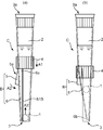
- FIG. 1 is a front view illustrating the configuration of the suction tip according to the first embodiment of the present invention.
- FIG. 2 is a side view for explaining the operation of the suction tip according to the first embodiment of the present invention.
- FIG. 3 is an explanatory diagram of a procedure for sucking an object using the suction tip according to the first embodiment of the present invention.
- FIG. 4 is a side view for explaining the operation of the suction tip according to the second embodiment of the present invention.
- FIG. 5 is a side view for explaining the operation of the suction tip according to the third embodiment of the present invention.
- FIG. 6 is an explanatory diagram for explaining the operation of the suction tip according to the fourth embodiment of the present invention.
- FIG. 7 is an explanatory diagram for explaining the operation of the suction tip according to the fifth embodiment of the present invention.
- FIG. 8 is an explanatory diagram illustrating the configuration of the suction tip C5 of the present embodiment.
- FIG. 1 is a front view illustrating the configuration of the suction tip C of the present embodiment.
- FIG. 2 is a side view for explaining the operation of the suction tip C of the present embodiment,
- FIG. 2 (a) is a side view for explaining a state before the suction port 3 is closed, and
- FIG. It is a side view explaining the state after closing the suction opening.
- the suction tip C is used by being attached to a suction pipette P (see FIG. 3A) which is a kind of suction device.
- the suction tip C is an experimental instrument provided with an internal passage 2a for sucking and temporarily holding the sucked object 1 when the user operates the suction pipette P to suck the object 1.
- the suction chip C includes a main body portion 2, a suction port 3, a moving member 4, and a closing member B provided with a contact piece 5. Each configuration will be described in detail later.
- the suction pipette P is a suction device having a tip portion that enters the opening portion Ca of the suction tip C.
- the suction pipette P sucks the object 1 by generating a suction force from the suction port 3 of the suction tip C when the user operates a push button (not shown) with the suction tip C attached.
- the size (internal volume) of the suction tip C is not particularly limited, and a suction tip having an internal volume of, for example, about 1 ⁇ L to 5 mL can be appropriately employed depending on the application.
- a suction tip having an internal volume of, for example, about 1 ⁇ L to 5 mL can be appropriately employed depending on the application.
- each configuration of the suction tip C of the present embodiment will be described.
- the target object 1 is a target object that is sucked from the set M of target objects (see FIG. 3A) using the suction tip C of the present embodiment.
- the type of collection M of objects there are no particular limitations on the type of collection M of objects, and examples include mixtures of particles having various shapes and particle sizes, cell culture solutions containing various sizes of cells and contaminants, and cell treatment solutions.
- the collection M of objects is a mixed slurry of particles having various shapes and the objects contained therein are sucked using the suction tip C, the sucked particles correspond to the objects 1.
- the collection M of objects is a cell culture solution or a cell treatment solution containing cells or contaminants of various sizes, and suctioning only cells of a predetermined shape using the suction tip C, suction is performed.
- the predetermined shaped cells correspond to the object 1.
- the object 1 to be sucked using the suction chip C of the present embodiment is preferably a living cell, and more preferably a living cell aggregate.
- the suction tip C of the present embodiment sucks the object 1 together with the set M of objects including the object 1 by sucking using the suction pipette P, and then closes the suction port 3. To do. Therefore, even if the suction by the suction pipette P is stopped while the suction port 3 of the suction tip C is immersed in the set M of objects, the target 1 falls into the set M of objects from the suction port 3. There is no.
- the suction tip C of this embodiment can be operated in a state where the suction port 3 is immersed in the set M of objects, the object 1 is not dried. Furthermore, since the suction tip C of this embodiment does not continue to apply a negative pressure to the sucked object 1, the object 1 is not deformed. As a result, it is possible to reduce the deviation of the shape of the target object 1 as a sample in the previous stage for various tests, improve the reliability of data in the fields of bio-related technologies and medicines, and improve work efficiency. Can contribute.
- Biologically-derived cell aggregates are generally formed by aggregating several to several hundred thousand individual cells, and normal cell aggregates have a substantially spherical shape.
- the test result obtained using such a cell aggregate derived from a living body is a living body in which the interaction between each cell is taken into consideration inside the cell aggregate than the test result obtained using one cell.
- a similar environment has been reconstructed, and results that take into account the functions of individual cells can be obtained, and the experimental conditions can be more consistent with the environment in vivo.
- the suction tip C of the present embodiment can work in the set M of objects so as not to dry the object 1 and does not continue to apply negative pressure to the sucked objects 1. Therefore, when the object 1 is a cell aggregate derived from a living body, more reliable results can be obtained in the fields of biotechnology and medicine by using the suction chip C of this embodiment.
- the size (diameter) of the cell aggregate is not particularly limited.
- the present invention can handle a cell aggregate having a diameter of, for example, about 80 to 800 ⁇ m by changing the size of the suction tip.
- the main body 2 is a suction path through which the object 1 passes when the object 1 is sucked using the suction tip C.
- the main body 2 is composed of a tube member in which a tubular passage 2a through which the sucked object 1 passes is formed.
- the thickness of the main body is not particularly limited, but if it is too thin, the strength will be low, and if it is too thick, it will be difficult to operate the tongue piece 6 described later.
- the inner diameter of the tubular passage 2a is not particularly limited as long as the object 1 can pass through.
- the inner diameter may be about 400 to 2000 ⁇ m.
- the material constituting the main body 2 is not particularly limited as long as it is a material used for a normal suction tip C.
- a material used for a normal suction tip C For example, polypropylene or polystyrene can be employed as the material.
- the method for producing the main body 2 is not particularly limited, and a normal method for producing the suction tip C can be employed. For example, a method of injecting these materials into a molding die in a molten state and molding can be employed.
- the suction port 3 is an opening for sucking the object 1 from the set M of objects by operating a suction device such as a suction pipette P to which the user has attached the suction tip C.
- the object 1 is sucked by the suction pipette P (see FIG. 3A) and introduced from the suction port 3 into the tubular passage 2a of the main body 2.
- the suction port 3 is formed at the tip of the main body 2.
- cell aggregates often have a substantially spherical shape. Therefore, when the user uses the suction tip C of the present embodiment having the circular suction port 3 to suck the target object 1 that is a cell aggregate, for example, a distorted cell aggregate that does not have a substantially spherical shape. A lump can be prevented from passing through the suction port 3 and entering the tubular passage 2a.
- the opening area of the suction port 3 may be appropriately adjusted according to the diameter of the object 1 to be sucked. That is, when the suction port 3 is formed larger than the object 1, the object 1 can be reliably sucked into the tubular passage 2 a. Moreover, when the target object 1 has a flexible property, when the suction port 3 is slightly smaller than the target object 1 or when the target object 1 is not spherical and the maximum diameter of the target object 1 exceeds the diameter of the suction port 3. Even in this case, the object 1 can be deformed flexibly and sucked into the tubular passage 2a. For example, as described above, when the cell aggregate is used as the object 1, and the size of the cell aggregate is 300 to 500 ⁇ m, the diameter of the suction port 3 may be about 200 to 600 ⁇ m.
- the shape of the suction port 3 included in the suction tip C of the present embodiment may be other than a circle and is not particularly limited.
- an optimal shape can be adopted as appropriate in accordance with the shape of the object 1.
- the user uses the suction tip C having a narrow shape of the suction port 3 so that a large spherical particle or flat shape is obtained. It is possible to prevent small particles from being sucked from the suction port 3.
- the moving member 4 moves up and down along the suction direction of the suction tip C, so that the contact piece 5 provided on the tongue piece 6 described later is provided. Press.
- the tongue piece 6 closes the suction port 3 through the pressed contact piece 5.
- the moving member 4 is provided to be movable up and down with respect to the main body 2. The procedure for closing the suction port 3 will be described in detail later.
- the moving member 4 is a cylindrical member provided with a hollow portion 4a.
- the moving member 4 is held at a substantially central position of the main body 2 in a state where the main body 2 is inserted through the hollow portion 4a.
- the moving member 4 is locked at a substantially central position of the main body portion by coming into contact with a contact piece 5 described later.
- the method of holding the moving member 4 at the substantially central position of the main body 2 is not particularly limited, and the main body 2 penetrates the hollow portion 4a of the moving member 4 from the suction port 3 side of the suction tip C.
- the hollow portion 4a of the moving member 4 may be held through the other end side opening 3a of the suction tip C (the end connected to the suction pipette P).
- the user When arranging the hollow part 4a of the moving member 4 through the suction port 3 side of the suction tip C, the user temporarily pushes down a contact piece 5 described later so that the hollow part 4a is in contact with the contact piece. 5 is moved to an upper side (the other end side opening 3a side) than the contact piece 5.
- the suction chip C of this embodiment illustrated the moving member 4 which moves up and down
- the moving method of the moving member 4 is not specifically limited, The contact piece 5 mentioned later is pressed and the suction port 3 is closed. Any moving method can be used.
- the suction method of the target object 1 will be described in detail later, it will be briefly described as follows. That is, as shown in FIG. 3A, the user attaches the suction tip C of the present embodiment to the suction pipette P that is a suction device, and immerses the suction port 3 in the set M of objects.
- the user After the user sucks the object 1 from the suction port 3, the user pushes it down with his hand or moves the moving member 4 in the direction of the arrow A 1 using a movement aid or the like, and closes the suction port with the tongue piece 6. .
- the moving member 4 may be slid with respect to the main body 2 so as to operate smoothly when moving up and down.
- the method for sliding is not particularly limited. Since the main body portion 2 of the suction tip C of the present embodiment is tubular and has a substantially circular cross section, a sliding layer made of a material having elasticity (for example, a urethane material) is provided on the inner peripheral wall of the moving member 4, The moving member 4 may be slid while contacting the sliding layer and the outer peripheral wall of the main body 2. Further, a guide strip along the moving direction of the moving member 4 may be provided on the outer peripheral wall of the main body 2, and a guide recess guided by the guide strip may be provided on the inner peripheral wall of the moving member 4.
- the material constituting the moving member 4 is not particularly limited, and a resin such as polypropylene or polystyrene can be used in the same manner as the main body 2. In addition to the resin, a non-corrosive metal that does not cause contamination with the object 1 can be adopted as the material.
- the closing member B closes the suction port 3 as shown in FIGS. 1, 2 (a) and 2 (b).
- the closing member B includes a contact piece 5 and a tongue piece 6 on which the contact piece 5 is formed.
- the contact piece 5 holds the moving member 4 in a contact state at a substantially central position of the main body 2.
- the abutting piece 5 protrudes from the outer peripheral surface of the tongue piece 6 in the vicinity of a base end portion 6 a of the tongue piece 6 described later.
- the contact piece 5 has a slope portion 5 a in which the protruding length on the radially outer side becomes longer from the base end portion 6 a of the tongue piece 6 toward the suction port 3 of the main body portion 2.
- the main body portion has a substantially cylindrical tube shape. Therefore, as the depressing member moves down, the moving member 4 moves in the direction of the arrow A ⁇ b> 1 while strongly contacting the slope portion 5 a. Since the contact piece 5 is provided in the vicinity of the base end portion 6a of the tongue piece 6, when pressed by the moving member 4, the tongue piece 6 is deformed with the base end portion 6a as a fulcrum in the arrow A2 direction.
- the slope portion of the contact piece 5 has an inclined surface whose protruding length gradually increases from the base end portion 6 a of the tongue piece 6 toward the suction port 3 of the main body portion 2.
- an engaging protrusion that engages with the lower end of the pushed-down moving member 4 or an engaging groove may be provided in the middle of the inclined surface.
- an engaging groove that engages the top of the slope portion 5a is provided on the inner peripheral wall of the moving member so that the moving member 4 that has moved a predetermined distance in the direction of the arrow A1 is engaged with the slope portion 5a. It may be configured.
- the tongue piece 6 is formed by providing a pair of slits (slit S1A and slit S1B) extending from the suction port 3 in the suction direction of the object 1 on the tube wall of the tube member of the main body 2.
- the ratio of the tongue piece 6 to the outer peripheral length of the main body portion 2 is not particularly limited, but usually the outer peripheral length of the main body portion 2 is d. In this case, it is about 0.1 to 0.5d.
- the width of the tongue piece 6 is less than 0.1 d, the suction port 3 may not be sufficiently closed.
- the width of the tongue piece 6 exceeds 0.5d, there is a possibility that it cannot be deformed to narrow the suction port 3 because the width is too large.
- the tongue piece 6 has the contact piece 5 protruding in the vicinity of the base end portion 6a. Therefore, when the contact piece 5 is pressed, the tongue piece 6 deforms with the base end portion 6a as a fulcrum. As shown in FIG. 2B, the distal end portion 6b of the tongue piece 6 on the suction port 3 side moves into the tubular passage 2a so as to close the suction port 3 due to the deformation of the base end portion 6a.
- the distal end portion 6b of the tongue piece 6 on the suction port 3 side is large even if the deformation amount of the base end portion 6a is small. As a result of being moved and pushed and bent into the tubular passage 2a, the suction port 3 can be easily closed to the extent that the object 1 does not fall from the suction port 3.
- “closed” means that the suction port 3 is deformed or the opening of the suction port 3 is set to such an extent that the target object 1 cannot fall and pass through the set M of target objects according to gravity. A state where the area is reduced. Specifically, as shown in FIG. 2B, the base end portion 6a of the tongue piece 6 is deformed when the moving member 4 moves while pressing the slope portion 6a of the contact piece 6, and the tip end The opening area of the suction port 3 is narrowed by greatly deforming the portion 6b. As a result, the suction port 3 is closed to such an extent that the object 1 cannot pass through, so that the object 1 cannot be dropped from the suction port 3 and is held in the tubular passage 2a.
- the arrow A1 indicates the moving direction of the moving member 4
- the arrow A2 indicates the moving direction of the contact piece 5 pressed by the moving member 4
- the arrow A3 indicates the deformation of the tongue piece 6.
- the target object 1 moving in the depth direction of the tubular passage 2a (downstream side in the suction direction) is shown.
- FIG. 3A is an explanatory diagram illustrating a state in which the object 1 has started to be sucked.
- FIG. 3B is an explanatory diagram for explaining a state where the suction of the object 1 is finished.
- FIG. 3C is an explanatory diagram illustrating a state where the suction port 3 is closed.
- a set M of objects is stored in a bottomed cylindrical container Co such as a beaker.
- the set M of objects is a liquid in which the objects 1 are dispersed.
- the user pushes a push button (not shown) of a suction pipette P (suction device) equipped with the suction tip C of the present embodiment, and the air in the suction tip C Is discharged.
- the suction tip C is immersed in the set M of objects.
- the depth at which the suction tip C is immersed is a depth at which at least the suction port 3 of the suction tip C and the entire slit S1B of the suction tip C are immersed in the set M of objects.
- the user pushes up the push button of the suction pipette P and sucks the object 1 together with the set M of objects from the suction port 3.
- the moving member 4 is locked at an initial position (a position where the abutting piece 5 is not pressed and abutted), and the suction port 3 is opened.
- An arrow A6 indicates the suction direction of the set M of objects to be sucked.
- the set M of objects including the object 1 is sucked from the suction port 3 (partially the slit S1B) of the suction tip C and introduced into the tubular passage 2a of the main body 2.
- the suction tip C of the present embodiment sucks the target object 1 together with the collection M of the target objects, so that no large negative pressure is applied to the target object 1 itself during suction. Therefore, the object 1 is gently introduced into the tubular passage 2a without being deformed.
- the number of objects 1 to be sucked at a time is not particularly limited, but in the present embodiment, the case where one object 1 is sucked is illustrated and described.
- the moving member 4 contacts the slope portion 5a of the contact piece 5 while moving the contact piece 5 radially inward of the main body 2 (in the direction of arrow A2). ). Since the contact piece 5 is provided in the vicinity of the base end portion 6 a of the tongue piece 6 as described above, the base end portion 6 a of the tongue piece 6 is deformed by being pressed by the moving member 4. Due to the deformation of the proximal end portion 6a, the distal end portion 6b of the tongue piece 6 moves into the tubular passage 2a so as to close the suction port 3. The passage area of the tubular passage 2a in the vicinity of the suction port 3 is narrowed by the pushed end 6b. Therefore, the object 1 moves in the depth direction (downstream direction of the suction direction) of the tubular passage 2a and is held in the tubular passage 2a.
- the suction chip C of the present embodiment does not drop the object 1 from the suction port 3 even when the sucked object 1 is transported in the set M of objects. Further, in the suction chip C of the present embodiment, since there is no need to keep the object 1 by suction, there is no possibility of sucking the set M of objects more than necessary, and the object by continuously sucking the object 1 The object 1 is not deformed or destroyed.
- FIG. 4 is an explanatory view for explaining the operation of the suction tip C1 of the present embodiment
- FIG. 4 (a) is a side view for explaining a state before the suction port 3 is closed
- FIG. It is a side view explaining the state after closing the suction opening.
- the main body 21 of the suction tip C1 of the present embodiment is the first except that two tongue pieces 61 are arranged opposite to each other in the main body 2. This is the same configuration as the suction tip C of the embodiment. For this reason, description of overlapping portions is omitted.
- the two tongue pieces 61 are formed by providing a pair of slits S2A and slits S2B, respectively.
- Each tongue piece 61 has a contact piece 51 protruding in the vicinity of the base end portion 61a. Similar to the contact piece 5 of the first embodiment, the contact piece 51 has a slope in which the projecting length on the radially outer side becomes longer from the base end portion 61 a of the tongue piece 61 toward the suction port 3 of the main body portion 2. Part 51a. When the user pushes down the moving member 4, the moving member 4 moves in the arrow A1 direction while abutting against the slope portion 51a.
- the contact piece 51 Since the contact piece 51 is provided in the vicinity of the base end portion 61a of the tongue piece 61, the contact piece 51 is deformed in the arrow A2 direction by using the base end portion 61a as a fulcrum when pressed by the moving member 4, and the front end portion 61b is changed. The tube is bent into the tubular passage 21a.
- the distal end 61b of the tongue piece 61 on the suction port 3 side moves into the tubular passage 21a so as to close the suction port 3 due to the deformation of the base end portion 61a.
- the suction port 3 is closed.
- the object 1 moves in the back direction of the tubular passage 21a (downstream in the suction direction) and is held in the tubular passage 21a.
- the suction tip C1 of this embodiment has two tongue pieces 61. Therefore, the user can hold the object 1 in the tubular passage 2a more reliably as compared with the case where the number of the tongue pieces 6 is one as in the suction tip C of the first embodiment. Moreover, since the suction tip C1 of this embodiment closes the suction port 3 using the two tongue pieces 61, the user can close the suction port 3 more reliably. Therefore, the suction chip C1 of the present embodiment can further reduce the opening area of the suction port 3 when closed. Even when the diameter of the object 1 is small, the user can hold the object 1 in the tubular passage 2a more reliably.
- the suction tip C1 of the present embodiment can shorten the moving distance of each tongue piece 61.
- the height of the contact piece 51 can be formed relatively low. As a result, the suction tip C1 of the present embodiment can save space, is easy for the user to operate, and improves convenience.
- the number of the tongue pieces 61 should just be two or more, and is not limited to two pieces. For example, you may provide three tongue pieces so that the separation distance of each tongue piece 61 may become substantially the same.
- the protrusion length of the contact piece 51 provided in the vicinity of the base end part 61a of each tongue piece 61 may be the same, and may differ. .
- the user prepares a plurality of tongue pieces provided with the contact pieces 51 having different projecting lengths, whereby a plurality of tongue pieces having different deformation amounts that are deformed when the contact pieces 51 are pressed against the moving member 4 are prepared. Can be prepared.
- the tip portion of the tongue piece having a large deformation amount moves into the tubular passage 21a before the tongue piece having a small deformation amount.
- the tongue piece with a small deformation amount moves the tip portion into the tubular passage 21a after the tongue piece whose tip portion has moved first. As a result, the user can more firmly close the suction port 3 using the tip portions of the two tongue pieces.
- FIG. 5 is an explanatory view for explaining the operation of the suction tip C2 of the present embodiment
- FIG. 5 (a) is a side view for explaining a state before the suction port 31 is closed
- FIG. It is a side view explaining the state after closing the suction port 31.
- the suction tip C2 of the present embodiment is the same as the suction tip C shown in the first embodiment or the second embodiment except that the suction port 31 is closed using the closing member B1 without using a tongue piece.
- the configuration is the same as the suction tip C1 shown. For this reason, description of overlapping portions is omitted.
- the main body 22 of the suction tip C2 of this embodiment is provided with a closing member B1.
- the closing member B1 has a locking portion 7 locked to the main body portion 22, one end (upper end 8a) fixed to the locking portion 7, and the other end side extending in a direction parallel to the suction path. And a lid portion 9 that is connected to the other end (lower end 8 b) of the barrel portion 8 and closes the suction port 31.
- the material constituting the closing part B1 is not particularly limited, and a resin such as polypropylene or polystyrene can be used in the same manner as the main body part 22.
- the locking part 7, the body part 8, and the lid part 9 may be configured and assembled from different materials, respectively, or may be configured integrally with the same material.
- a method of injecting a molten resin into a molding die can be employed.
- the locking part 7 locks the closing member B1 on the main body part 22 of the suction tip C2.
- the structure of the locking portion 7 is not particularly limited as long as it can be locked to the outer peripheral surface of the main body portion.
- locking part 7 which consists of a ring-shaped member is employ
- the mounting method of the locking portion 7 there is no particular limitation on the mounting method of the locking portion 7.
- a method of inserting and mounting the main body portion 22 of the suction tip C ⁇ b> 2 so as to pass through the ring of the locking portion 7 may be employed. it can.
- the material constituting the locking portion is a material that can slightly expand and contract with respect to the main body portion 22.
- a locking projection may be provided on a part of the inner peripheral surface of the ring of the locking portion, and a locking recess that can be engaged with the locking projection may be provided on the outer peripheral surface of the main body portion 22.
- the closing member B1 may be integrally formed with a molding die.
- the ring-shaped member is a member that winds a part (preferably a half or more) of the main body portion 22 in addition to a member that winds the entire circumference of the outer peripheral surface of the main body portion 22 as shown in FIG. There may be.
- winding a part of the main body 22 it is preferable to provide the engaging portion described above in order to lock the ring-shaped member to the main body 22 more stably.
- the barrel portion 8 is a rod-shaped member whose upper end 8a is connected to the engaging portion 7 and whose lower end 8b side hangs down in the vertical direction.
- the body portion 8 is configured so that the lid portion 9 moves to a position where the suction port 31 can be closed when the contact piece 52 described later is pressed by the moving member 4 and the vicinity of the upper end 8a is deformed. It is provided to determine the position.
- the barrel 8 has a contact piece 52 in the vicinity of the upper end 8a. As shown in FIG. 5A, the contact piece 52 protrudes in the vicinity of the upper end 8 a of the body portion 8.
- the contact piece 52 has a slope portion 52a whose projecting length becomes longer from the upper end 8a of the body portion 8 to the lower end 8b with the lid portion 9.
- the moving member 4 moves in the direction of the arrow A1 while contacting the slope portion 52a. Since the contact piece 52 is provided in the vicinity of the upper end 8a of the trunk portion 8, the contact member 52 is pressed by the moving member 4 to deform the closing member B1 with the upper end 8a as a fulcrum in the arrow A4 direction. As a result, the lid 9 moves to a position where the suction port 31 is closed, and closes the suction port 31.
- the contact piece 52 included in the suction tip C2 of the present embodiment is formed integrally with the body portion 8 and is formed by deforming a part of the body portion 8, but the contact piece 52 and the body portion are formed.
- the shape of 8 is not limited to this.
- the user may prepare the straight body 8 and project the contact piece 52 in the vicinity of the upper end 8a.
- a seal member (not shown) that fits into the suction port 31 when the lid portion 9 is moved to the closed position is provided on the surface of the lid portion. May be.
- the hemispherical seal member plugs the suction port 31 tightly. Can be configured to.
- the lid portion 9 closes the suction port 31.
- the lid portion 9 is provided on the body portion 8 via the lower end 8b. As described above, the lid portion 9 closes the suction port 31 in conjunction with the deformation of the upper end 8 a of the body portion 8 when the contact piece 52 formed on the body portion 8 is pressed by the moving member 4.
- the closure member B1 can be used by being attached to a conventional suction tip, so that convenience is improved.
- the suction chip C2 of this embodiment does not need to be provided with the slit S1A (see FIG. 1) or the like in the main body portion 2, convenience in production is improved. Furthermore, even if the diameter of the object 1 is small enough to prevent the suction port 31 from being completely closed by the tongue piece (see FIG. 1), the suction port 31 is not affected by the size of the object 1. Can be closed.
- the suction tip for example, the suction tip C described in detail in the first embodiment
- the slit S1A is formed
- the slit S1A portion is not deeply immersed to the extent that it is immersed in the set M of the target, the target 1 cannot be sucked sufficiently.
- the slit S1A is not formed in the suction chip C2 of the present embodiment. Therefore, when the user sucks the object 1 using the suction chip C2 of the present embodiment, the user sufficiently sucks the object 1 only by immersing at least the suction port 31 in the set M of objects. be able to.
- the suction tip C2 of this embodiment is convenient when the amount of the set M of objects is small or when a rare sample is handled. Further, since the suction tip C2 of the present embodiment can close the suction port 31, it can be easily transported not only in the liquid but also in the outside air without dropping the sucked object 1.
- FIG. 6 is an explanatory view for explaining the operation of the suction tip C3 of the present embodiment.
- FIG. 6 (a) is a side view for explaining a state before the suction port 32 is closed, and FIG. 6 (b). These are the schematic diagrams by the side of the bottom face of the suction port 32 before closing the suction port 32.
- FIG. 6 (b) is a side view for explaining a state before the suction port 32 is closed
- the main body 23 of the suction chip C3 of the present embodiment is provided with a single slit S3 extending in the vertical direction of the main body 23, Except for the configuration in which the movable portion X that can be reduced in diameter is wound inside the non-movable portion Y, it is the same as the suction tip C1 of the first embodiment. For this reason, description of overlapping portions is omitted.
- the main body 23 is separated into a movable part X and a non-movable part Y by a single slit S3.
- the slit S ⁇ b> 3 extends in the tube wall of the tube member of the main body portion 23 from the suction port 32 a in the suction direction of the object 1, and extends in one direction (approximately at the center position of the main body portion 23 In this embodiment, it is formed so as to curve in the upper left direction of the drawing.
- Reference sign S ⁇ b> 3 a indicates an end portion of the slit S ⁇ b> 3 formed in the main body portion 23.
- the main body part 23 is separated into a movable part X and a non-movable part Y by a slit S3.
- the movable part X is a part that is wound inside the non-movable part Y, and is usually formed in the bending direction of the slit S3 (in the present embodiment, the left direction in the drawing).
- the slit S3 is formed only up to substantially the center position of the main body portion 23 and is a single slit, and therefore the boundary between the movable portion X and the non-movable portion Y is uniquely determined. Not.
- the abutting piece 53 is provided on the movable part X and upstream of the end S3a of the slit S3 in the suction direction of the collection of objects.
- the contact piece 53 has a slope portion 53a in which the protruding length on the radially outer side becomes longer from the end portion S3a toward the suction port 32a.
- the contact piece 53a is provided to be inclined in a direction rotated by a predetermined angle from the axial direction of the main body portion 23 so that the top portion 53b is positioned close to the slit S3. .
- the opening area of the suction port 32a is larger than the diameter of the object 1 as shown in FIG. Therefore, the object 1 can be sucked and introduced into the tubular passage.
- FIGS. 6A and 6C when the user pushes down the moving member 4 in the direction of the arrow A1, the moving member 4 moves in the direction of the arrow A1 while contacting the slope portion 53a.
- the contact piece 53 is pressed in a direction (arrow A5 direction) in which the movable part X enters inside the non-movable part Y.
- FIG. 6C is a side view illustrating a state after the suction port 32 is closed.
- Reference numeral X ⁇ b> 1 indicates the movable portion X that has entered the inside of the non-movable portion Y.
- the contact piece 53 Since the contact piece 53 is provided on the movable part X, the stress generated when the user moves the moving member 4 is transmitted to the movable part X, and the movable part X is deformed. As described above, the contact piece 53 is provided in a direction rotated by a predetermined angle from the axial direction of the main body 23. Therefore, the stress transmitted to the movable part X acts in a direction in which the movable part X enters the inside of the non-movable part Y, and deforms the movable part X to the inside of the non-movable part Y.
- the deformation amount of the movable part X is smaller at a position close to the contact piece 53 and larger at a position far from the contact piece 53. Therefore, the movable part X at a position close to the suction port 32a is greatly deformed when the contact piece 53 presses the moving member 4.
- the suction port 32 b is greatly reduced in diameter so that the opening area is smaller than the diameter of the object 1 and is closed.
- FIG. 6D is a schematic view of the bottom surface side of the suction port 32b after the suction port 32a is closed. As is clear from a comparison between FIG. 6B and FIG. 6D, the reduced diameter suction port 32b is deformed to be smaller than the diameter of the object 1.
- the suction chip C3 of the present embodiment forms a single slit S3 and allows the movable part X to enter the inside of the non-movable part Y. Therefore, at least two slits (slit S1A and slit S1B) Compared with the case where the tongue piece 6 (see FIG. 1) formed by the above is manufactured, the manufacture becomes easier. Moreover, since the movable part X is comprised from the main-body part 2 itself, the attraction
- the ratio of the opening area of the suction port after closing the suction port 32 (reduction ratio) with respect to the opening area of the suction port before closing the suction port 32 is not particularly limited. What is necessary is just to determine suitably according to a diameter.
- the diameter reduction ratio is set so that the diameter of the suction port 32 is about 270 to 450 ⁇ m. Can be determined.
- the user adjusts the width of the slit S3, the installation position of the contact piece 53, the protruding length of the contact piece 53, and the like so that the determined diameter reduction ratio is obtained.
- FIG. 7 is an explanatory view for explaining the operation of the suction tip C4 of the present embodiment.
- FIG. 7 (a) is a side view for explaining a state before the suction port 3 is closed
- FIG. 7 is a schematic diagram of the bottom surface side of the suction port 3 before the suction port 3 is closed
- FIG. 7C is a schematic diagram of the bottom surface side of the suction port 3 after the suction port 3 is closed.
- the suction tip C4 of the present embodiment presses the contact piece 54 against the inner surface of the moving member 41 by rotating the moving member 41.
- the configuration is the same as that of the suction tip C of the first embodiment except that the portion 42 is formed. For this reason, description of overlapping portions is omitted.
- the moving member 41 of the present embodiment is provided on the arrangement position of the contact piece 54 provided at a substantially central position of the main body 2 and the main body 2 is inserted. Yes. Since the moving member 41 provided in the suction chip C4 of this embodiment presses the contact piece 54 by the rotational movement in the arrow A6 direction, the horizontal position of the moving member 41 does not change.
- a flange (not shown) that circulates around the outer wall of the main body is provided on the outer wall of the main body 2.
- An engaging groove that engages with the flange may be provided on the inner periphery of the moving member 41.
- an engagement groove that engages with the top 54 a of the contact piece 54 may be provided on the inner periphery of the moving member 41.
- a flange (not shown) that abuts the rectangular parallelepiped abutting piece 54 is provided on the inner peripheral wall of the moving member 41 so that the moving member 41 is abutted. It may be held in contact with the contact piece 54.
- the inner peripheral surface of the moving member 41 is sucked from the non-pressing portion 43 where the contact piece 54 is located in a state before the suction port 3 is closed.
- the moving member 41 is formed so that its thickness gradually increases over the pressing portion 42 where the contact piece 54 is located in a state after the mouth 3 is closed.
- Reference numeral 41A indicates a moving member before pressing the contact piece 54
- reference numeral 41B indicates a moving member after pressing the contact piece 54.
- the user gradually moves the contact piece 54 in the arrow A7 direction by rotating the moving member 41 in the arrow A6 direction.
- the rotation direction of the moving member 41 is not limited to the arrow A6 direction, and may be the reverse direction of the arrow A6 direction.
- the direction in which the thickness gradually increases on the inner peripheral wall of the moving member 41 needs to be reversed. That is, as shown in FIGS. 7B and 7C, the moving member 41 included in the suction tip C4 of this embodiment is gradually inner circumferential wall of the moving member 41 in the direction opposite to the arrow A6 direction. Is formed so as to have a large thickness. On the other hand, when the rotation direction is the direction opposite to the arrow A6 direction, the direction in which the inner peripheral wall of the moving member 41 is formed to have a large thickness needs to be the arrow A6 direction.
- the moving member 41 of this embodiment is not limited to this.
- a step (not shown) may be provided stepwise to increase the thickness.
- the abutting piece 54 is kept at a level difference that can be climbed up by rotating the moving member 41.
- one or more convex portions (not shown) can be provided while the thickness of the inner peripheral surface of the moving member 41 is gradually increased.
- the contact piece 54 is provided in the vicinity of the base end portion 6a of the tongue piece 6 in the same manner as the suction tip C of the first embodiment. Therefore, when the contact piece 54 is pressed by the moving member 41 and moves in the arrow A7 direction, the tongue piece 6 is deformed with the base end portion 6a as a fulcrum. The tip 6b of the tongue piece 6 moves into the tubular passage 2a, blocks the passage of the object 1 in the tubular passage 2a, and closes the suction port 3.
- the shape of the contact piece 54 is not particularly limited.
- a contact piece having a slope portion 54a is employed in the same manner as the contact piece 5 of the first embodiment.
- a rectangular parallelepiped or trapezoidal contact piece can be employed.
- the suction tip C4 of the present embodiment has a particularly limited degree of rotation of the moving member 41. Not. When the diameter of the object 1 is relatively large, the suction port 3 may be sufficiently closed without rotating until the contact piece 54 is positioned at the pressing portion 42.
- the moving member 41 that presses the contact piece 54 only by rotational movement without changing the horizontal position of the moving member 41 is exemplified, but the moving member 41 of the present embodiment is not limited to this. That is, the moving member 41 having the shape of the inner surface shown in the present embodiment (see FIG. 7B) is arranged at the position shown in the first embodiment (see FIG. 2A), and the arrow A1 You may employ
- the suction chip C4 of this embodiment can change the opening area of the suction port 3 in two stages, it becomes possible to select the diameter of the target object 1 in more detail.
- the shape of the contact piece 54 is not a rectangular parallelepiped shape, but is the same as the contact piece 5 of the first embodiment. It is preferable to have a slope portion.
- FIG. 8 is an explanatory diagram illustrating the configuration of the suction tip C5 of the present embodiment.
- the suction tip C5 of the present embodiment is the first implementation except that the moving member 42 is configured to be movable by the user operating the push button Bo of the suction pipette P1. It is the structure similar to the suction tip C of a form. For this reason, description of overlapping portions is omitted.
- the suction pipette P1 is a kind of suction device, and can suck a target by attaching a suction tip C5 to the tip. The operation of sucking and discharging the object using the suction pipette P1 will be described in detail later.
- the moving member 42 included in the suction tip C5 of the present embodiment is configured to move up and down in conjunction with the operation of the push button Bo.
- the axis S transmits the stress applied by the user to the push button Bo in the downward direction.
- the shaft S is provided with a hole Sa that is a long hole that is long in the vertical direction.
- the connecting portion Ba is fitted in the hole Sa so as to be movable up and down.
- the connecting portion Ba is in contact with the upper end of the hole Sa in a state where the user does not push down the push button Bo.
- the shaft S is connected to the link member L1 via the connecting portion Ba.
- the shaft S is inserted through a suction passage (not shown) provided inside the suction pipette P1. The user pushes the push button Bo to push the shaft S downward, and discharges air in the suction passage.
- the material of the shaft is not particularly limited. Usually, a metal shaft is employed.
- the link member L1 is provided inside the suction pipette P1.
- the link member L1 connects the connecting portion Ba and the connecting portion Bb to both ends with the fulcrum p as a fulcrum.
- the fulcrum p is provided inside the suction pipette P1, and its position is fixed.
- An arrow A7 indicates the moving direction of the connecting portion Ba.
- the connecting portion Ba is provided at one end of the link member L1.
- the fulcrum p is fixed and the position does not change. Therefore, the connecting portion Bb provided at the other end of the link member L1 is pulled up by pushing down the push button Bo.
- Arrow A8 indicates the moving direction of the connecting portion Bb.
- the link member L2 has one end connected to the connecting portion Bb and the other end connected to the moving member 42. Therefore, when the connecting portion Bb moves in the arrow A8 direction, the moving member 42 moves to the initial position (a position where the contact piece is not pressed). At this time, the suction port is open, and the air in the suction tip C5 (air in the suction passage) is discharged by the push-down operation of the push button Bo.
- the method for connecting the shaft S and the link member L1 by the connecting portion Ba is not particularly limited.
- a ball shaft may be provided on the shaft S, and a bearing corresponding to the ball shaft may be provided on the link member L1.
- the shaft S and the link member L1 may be joined by a joining method such as rivet joining.
- the method for connecting the link member L1 and the link member L2 by the connecting portion Bb is not particularly limited.
- a method similar to the method of connecting the shaft S and the link member L1 by the connecting portion Ba described above can be employed.
- the method for connecting the link member L2 and the moving member 42 is not particularly limited.
- the link member L2 and the moving member 42 may be formed integrally, and when prepared as separate members, an engaging portion (not shown) is provided in a part of the link member L2, and the moving member 42 is provided. You may engage with the to-be-engaged part (not shown).
- the suction tip C5 from which the air has been discharged is in a state where the object can be sucked.
- the user sucks an object (not shown) from the suction port 3 by pulling up the push button Bo.
- the shaft S and the connecting portion Ba, the link member 41, the connecting portion Bb, and the link member 42 are interlocked, and the moving direction of the shaft S and the moving direction of the link member L2 are opposite to each other. Since the push button Bo is pulled up, the moving member 42 is pushed down in the direction of the arrow A1 as a result.
- the contact piece 5 protrudes in the vicinity of the base end portion 6 a of the tongue piece 6. Therefore, when the contact piece 5 is pressed by the moving member 42, the tongue piece 6 is deformed with the base end portion 6a as a fulcrum. As a result, the tip 6b moves into the tubular passage and closes the suction port 3.
- the connecting portion Ba is fitted in the hole portion Sa so as to be movable up and down. Therefore, the connecting portion Ba moves from the state of being in contact with the upper end of the hole Sa to the state of being in contact with the lower end in the initial stage of the pulling-up operation of the push button Bo. After the connecting portion Ba is in contact with the lower end of the hole Sa, the push button Bo is further lifted, whereby the link member 41, the connecting portion Bb, and the link member 42 are interlocked with each other to move the moving member 42. Is pushed down in the direction of arrow A1.
- the user depresses the push button Bo again when discharging the object.
- the push button Bo since the shaft S and the connecting portion Ba, the link member 41, the connecting portion Bb, and the link member 42 are interlocked with each other, when the push button Bo is pressed down, the moving member 42 is pulled up in the arrow A8 direction. Returning to the initial position, the suction port 3 is opened. At this time, since the push button Bo is depressed, the object held in the suction passage is discharged from the suction port 3.
- the suction tip C5 of this embodiment operates in conjunction with the push button Bo of the suction pipette P1, and the suction operation of the pipette P1 includes the closing operation of the suction port. High and convenient.
- the hole part Sa is not essential.
- the connecting portion Ba may be directly connected to the shaft S or the link member L1.
- a suction tip includes a main body portion provided with a suction path for sucking an object therein, a suction port formed at the tip of the main body portion for sucking the object, and the main body.
- a movable member provided movably with respect to the portion and a contact piece pressed by the movable member are provided in part, and the suction member is closed by being pressed by the movable member via the corresponding piece. And a closing member.
- the suction member can be closed by moving the closing member by moving the moving member and pressing the contact piece. Therefore, even if the sucked object is transported not only in the outside air but also in the liquid, the object does not fall from the suction port. Further, since it is not necessary to keep the object by suction, the object is not deformed or broken by continuing to suck the object.
- the main body portion is made of a tube member having a tubular passage serving as the suction path therein, and the closing member is provided with a slit extending in the suction direction of the object from the suction port on the tube wall of the tube member. It is preferable that the main body is formed to be deformable in the vicinity of the suction port.
- the closing member is deformed, the suction port is closed in various modes, and the sucked object can be held in the suction path.
- the closing member includes a tongue piece formed between the slits and a contact piece projecting from the tongue piece by providing the pair of slits, and the contact piece is pressed. It is preferable that the tongue piece is deformed to close the suction port.
- the present invention has such a configuration, so that the number of parts is small and the object can be held in the main body with a simple configuration.
- the present invention can hold the object in the main body more reliably by having such a configuration. Moreover, even when the size of the object is small compared to the case where the number of tongue pieces is one, the object can be more reliably held in the main body.
- the tongue pieces are arranged to face each other on the tube wall of the tube member.
- the present invention can stably hold an object in the main body by having such a configuration. Moreover, compared with the case where the number of tongue pieces is one, the moving distance of each tongue piece can be shortened, it is easy for a user to operate, and the convenience improves.
- the closing member includes a locking portion locked to the main body portion, one end fixed to the locking portion, and the other end extending in a direction parallel to the suction path, and a part of the contact piece It is preferable to have a barrel portion provided with a lid portion that is formed at the other end of the barrel portion and closes the suction port.
- the closure member can be used by being attached to a conventional suction tip, so that convenience is improved. Moreover, since it is not necessary to provide a slit etc. in the main-body part of a suction tip, the convenience at the time of manufacture improves. Furthermore, even if the diameter of the object is small enough to prevent the tongue from closing the suction port, the suction port can be closed regardless of the size of the object.
- the closing member includes a movable part that can be reduced in diameter by providing a single slit, and the contact piece that protrudes from the movable part, and the contact piece is pressed. Accordingly, it is preferable that the movable portion has a reduced diameter to close the suction port.
- the present invention is easy to manufacture as compared with the case of producing a tongue piece that requires at least two slits by having such a configuration. Moreover, since the movable part is comprised from the main-body part itself, it is comparatively sturdy, there is little consumption, and durability of a suction tip can be kept high.
- the selection object is a living cell.
- the present invention can work in a liquid so that the target is not dried against a biological cell that is subject to damage due to drying or suction, and suction. Since the suction tip does not continue to apply negative pressure to the target object, individual differences in the target object as a sample can be suppressed as much as possible before the various tests, and the reliability of data in the fields of biotechnology and medicine This can improve work efficiency and contribute to work efficiency.
- the selection object is a cell aggregate derived from a living body.
- the present invention can obtain a result that takes into account the function of individual cells, and can further improve the experimental conditions in vivo than the test results obtained using a single cell. Therefore, it is possible to provide a suction tip that can obtain more reliable results in the fields of biotechnology and medicine.
Landscapes
- Health & Medical Sciences (AREA)
- Clinical Laboratory Science (AREA)
- Chemical & Material Sciences (AREA)
- Chemical Kinetics & Catalysis (AREA)
- Apparatus Associated With Microorganisms And Enzymes (AREA)
Abstract
対象物を吸引するための吸引経路を内部に備えた本体部と、該本体部の先端に形成され、対象物を吸引するための吸引口と、前記本体部に対して移動自在に設けられた移動部材と、一部に前記移動部材により押圧される当接片が設けられ、該当接片を介して前記移動部材に押圧されて前記吸引口を閉鎖する閉鎖部材と、を有する吸引チップ。このような構成を採用することにより、移動部材を移動させて、当接片を押圧することにより、閉鎖部材を移動させて吸引口を閉鎖することができる。そのため、吸引した対象物を液体中で運搬する場合であっても、吸引口から対象物が落下することがない。また、対象物を吸引により保持し続ける必要がないため、対象物を吸引し続けることによる対象物の変形や破壊を起こすことがない。
Description
本発明は、吸引チップに関する。より詳細には、液体中において、吸引した対象物が吸引口より落下することのないよう吸引口を閉鎖し得る吸引チップに関する。
従来、種々の分野において、比較的少量の液体等を一定容積吸い取って計量するための吸引ピペットが用いられている。特に、生化学実験では、先端に吸引チップを装着して使用するプッシュボタン式の吸引ピペットが多用されている。
吸引する対象物には、液体だけでなく、液体中に含まれる粉体、粒子、細胞等が含まれる。これら粉体、粒子、細胞等は、外気と接触することにより乾燥して性状が劣化したり、細胞の場合には死細胞となる可能性がある。そのため、これら対象物の取り扱いは、迅速に、空気に曝すことなく液体中で行われることが好ましい。特に、対象物が柔らかい性状である場合には、負圧を加えると対象物にダメージを与えてしまう可能性があるため、穏やかに吸引し、吸引チップ内に誘導してからは負圧を加えないことが好ましい。また、吸引により吸引チップ内を負圧に保ち続けることにより、必要以上に液体を吸引するおそれがある。
このような問題に鑑みて、特許文献1には、対象物を吸引するノズルの周囲に、カップ状の収容部を設けた吸引ピペットが開示されている。特許文献1の吸引ピペットは、吸引口で対象物を吸引して保持しながら、カップ状の収容部で対象物を保護する。また、特許文献2には、先端に中空領域を備え、液体とともに対象物を中空領域内に保持することのできる細胞捕捉用ピペットが開示されている。特許文献2の細胞捕捉用ピペットは、対象物を吸引した後、外気中を運搬する際には吸着口から対象物を放すため、常時吸引することによる対象物へのダメージが軽減される。
しかしながら、特許文献1に記載の吸引ピペットは、ノズルで対象物を吸引し続ける必要があるため、対象物に負圧が加えられ続け、対象物を劣化させたり破壊する、という問題がある。特許文献2の細胞捕捉用ピペットでは、外気中を運搬している際には、ピペット先端の開口部と、保持されている液体との間に表面張力が働くため、対象物は落下しないが、液体中で対象物を運搬する際には、このような表面張力が働かないため、対象物が落下してしまう、という問題がある。その結果、いずれの刊行物においても、吸引した対象物を液体中で運搬する際には、対象物をノズルで吸引し続ける必要があり、必要以上に液体を吸引するおそれがあるとともに、対象物を変形させたり破壊させたりする可能性がある。
本発明は、このような従来の問題に鑑みてなされたものであり、吸引した対象物を、外気中だけでなく液体中で運搬する場合においても、対象物を吸引により保持し続けて変形させたり破壊させたりすることがなく、かつ、吸引口から落下させることがない吸引チップを提供することを目的とする。
本発明の一局面による吸引チップは、対象物を吸引するための吸引経路を内部に備えた本体部と、該本体部の先端に形成され、対象物を吸引するための吸引口と、前記本体部に対して移動自在に設けられた移動部材と、一部に前記移動部材により押圧される当接片が設けられ、該当接片を介して前記移動部材に押圧されて前記吸引口を閉鎖する閉鎖部材と、を有することを特徴とする。
本発明の目的、特徴および利点は、以下の詳細な説明と添付図面とによって、より明白となる。
(第1の実施形態)
以下に、本発明の第1の実施形態の吸引チップCについて、図面を参照しながら詳細に説明する。図1は、本実施形態の吸引チップCの構成を説明する正面図である。図2は、本実施形態の吸引チップCの動作を説明する側面図であり、図2(a)は吸引口3を閉鎖する前の状態を説明する側面図であり、図2(b)は吸引口3を閉鎖した後の状態を説明する側面図である。
以下に、本発明の第1の実施形態の吸引チップCについて、図面を参照しながら詳細に説明する。図1は、本実施形態の吸引チップCの構成を説明する正面図である。図2は、本実施形態の吸引チップCの動作を説明する側面図であり、図2(a)は吸引口3を閉鎖する前の状態を説明する側面図であり、図2(b)は吸引口3を閉鎖した後の状態を説明する側面図である。
<吸引チップCについて>
吸引チップCは、吸引装置の1種である吸引ピペットP(図3(a)参照)に装着して使用される。吸引チップCは、ユーザが吸引ピペットPを操作して対象物1を吸引する際に、吸引した対象物1を吸引して一時的に保持するための内部通路2aを備えた実験器具である。吸引チップCは、本体部2と、吸引口3と、移動部材4と、当接片5が設けられた閉鎖部材Bと、を有する。各構成については、後記により詳述する。吸引ピペットPは、吸引チップCの開口部Caに進入する先端部を有する吸引装置である。吸引ピペットPは、吸引チップCを装着した状態でユーザがプッシュボタン(図示せず)を操作することにより、吸引チップCの吸引口3から吸引力を発生させて、対象物1を吸引する。
吸引チップCは、吸引装置の1種である吸引ピペットP(図3(a)参照)に装着して使用される。吸引チップCは、ユーザが吸引ピペットPを操作して対象物1を吸引する際に、吸引した対象物1を吸引して一時的に保持するための内部通路2aを備えた実験器具である。吸引チップCは、本体部2と、吸引口3と、移動部材4と、当接片5が設けられた閉鎖部材Bと、を有する。各構成については、後記により詳述する。吸引ピペットPは、吸引チップCの開口部Caに進入する先端部を有する吸引装置である。吸引ピペットPは、吸引チップCを装着した状態でユーザがプッシュボタン(図示せず)を操作することにより、吸引チップCの吸引口3から吸引力を発生させて、対象物1を吸引する。
吸引チップCの大きさ(内容積)としては特に限定されず、用途に応じて、たとえば1μL~5mL程度の内容積を有する吸引チップを適宜採用することができる。以下、本実施形態の吸引チップCの各構成について説明する。
<対象物1について>
対象物1は、本実施形態の吸引チップCを用いて、対象物の集合M(図3(a)参照)から吸引される対象物である。
対象物1は、本実施形態の吸引チップCを用いて、対象物の集合M(図3(a)参照)から吸引される対象物である。
対象物の集合Mの種類としては特に限定されないが、種々の形状や粒子径を有する粒子の混合物、種々の大きさの細胞や夾雑物を含んだ細胞培養液や細胞処理液などが挙げられる。たとえば、対象物の集合Mが、種々の形状の粒子の混合スラリーであり、吸引チップCを用いてその中に含まれる対象物を吸引する場合、吸引された粒子が対象物1に該当する。同様に、対象物の集合Mが、種々の大きさの細胞や夾雑物を含んだ細胞培養液や細胞処理液であり、吸引チップCを用いて所定の形状の細胞のみを吸引する場合、吸引された所定の形状の細胞が対象物1に該当する。
本実施形態の吸引チップCを用いて吸引する対象物1としては、生体由来の細胞であることが好ましく、より好ましくは、生体由来の細胞凝集塊である。
生体由来の細胞は、乾燥に弱く、柔らかい性状を有している。そのため、生体由来の細胞は、外気と接触して乾燥したり、吸引時に負圧が加わることにより変形すると、性状が劣化したり、ときには死細胞となる場合がある。本実施形態の吸引チップCは、吸引ピペットPを用いて吸引することにより、対象物1を、該対象物1が含まれる対象物の集合Mとともに穏やかに吸引し、その後に吸引口3を閉鎖する。そのため、対象物の集合Mに吸引チップCの吸引口3が浸漬している状態において吸引ピペットPによる吸引をやめても、吸引口3から対象物1が対象物の集合Mの中に落下することがない。また、本実施形態の吸引チップCは、吸引口3が対象物の集合Mに浸漬した状態で作業ができるため、対象物1を乾燥させることがない。さらに、本実施形態の吸引チップCは、吸引した対象物1に負圧を加え続けることがないため、対象物1を変形等させることがない。その結果、各種試験に供する前段階において、試料である対象物1の形状の偏差を小さくすることができ、バイオ関連技術や医薬の分野におけるデータの信頼性が向上するとともに、作業の効率化に寄与し得る。
生体由来の細胞凝集塊(スフェロイド spheroid)は、一般に、個々の細胞が数個~数十万個凝集して形成され、正常な細胞凝集塊は略球形を呈している。そして、このような生体由来の細胞凝集塊を用いて得た試験結果は、1個の細胞を用いて得た試験結果よりも、細胞凝集塊の内部に各細胞間の相互作用を考慮した生体類似環境が再構築されており、個々の細胞の機能を考慮した結果が得られ、かつ、より生体内における環境に即した実験条件に揃えることができる。上記のとおり、本実施形態の吸引チップCは、対象物1を乾燥させないよう対象物の集合Mの中で作業ができ、かつ、吸引した対象物1に負圧を加え続けることがない。そのため、対象物1が生体由来の細胞凝集塊の場合には、本実施形態の吸引チップCを用いることにより、バイオ関連技術や医薬の分野においてさらに信頼性の高い結果を得ることができる。
細胞凝集塊の大きさ(径)としては特に限定されない。本発明は、吸引チップの大きさを変更することにより、たとえば80~800μm程度の径を有する細胞凝集塊を取り扱うことができる。
<本体部2について>
本体部2は、図1に示されるように、吸引チップCを用いて対象物1を吸引する際に対象物1が通過する吸引経路である。本体部2は、内部に、吸引した対象物1が通過する管状通路2aが形成されたチューブ部材からなる。
本体部2は、図1に示されるように、吸引チップCを用いて対象物1を吸引する際に対象物1が通過する吸引経路である。本体部2は、内部に、吸引した対象物1が通過する管状通路2aが形成されたチューブ部材からなる。
本体部の厚みは、特に限定されないが、薄すぎると強度が低くなり、厚すぎると後述する舌片6の操作が困難となるため、100~600mm程度を採用することが好ましい。
管状通路2aの内径としては特に限定されず、対象物1が通過し得る大きさであればよい。たとえば、細胞凝集塊を対象物1とする場合において、細胞凝集塊の大きさが300~500μmである場合には、内径は、400~2000μm程度であればよい。
本体部2を構成する材料としては、通常の吸引チップCに使用される材料であれば特に限定されない。たとえば、材料として、ポリプロピレンまたはポリスチレン等を採用することができる。本体部2の作製方法としては特に限定されず、通常の吸引チップCの製造方法を採用することができる。たとえば、これらの材料を溶融状態で成型金型に注入し、成形する方法を採用することができる。
<吸引口3について>
吸引口3は、ユーザが吸引チップCを装着した吸引ピペットP等の吸引装置を操作することにより対象物の集合Mから対象物1を吸引するための開口である。対象物1は、吸引ピペットP(図3(a)参照)により吸引され、吸引口3から本体部2の管状通路2a内に導入される。吸引口3は、本体部2の先端に形成される。
吸引口3は、ユーザが吸引チップCを装着した吸引ピペットP等の吸引装置を操作することにより対象物の集合Mから対象物1を吸引するための開口である。対象物1は、吸引ピペットP(図3(a)参照)により吸引され、吸引口3から本体部2の管状通路2a内に導入される。吸引口3は、本体部2の先端に形成される。
上記のとおり、細胞凝集塊は、略球形を呈することが多い。そのため、ユーザは、円形の吸引口3を有する本実施形態の吸引チップCを用いて細胞凝集塊である対象物1を吸引する場合には、たとえば略球形を呈していない歪な形状の細胞凝集塊が吸引口3を通過して管状通路2a内に進入することを防ぐことができる。
吸引口3の開口面積は、吸引する対象物1の径に合わせて適宜調整すればよい。すなわち、吸引口3が対象物1よりも大きく形成されている場合、対象物1は、確実に管状通路2a内に吸引され得る。また、対象物1が柔軟な性状を有する場合には、吸引口3が対象物1よりも少し小さい場合や、対象物1が球形でなく対象物1の最大径が吸引口3の径を超える場合であっても、対象物1は柔軟に変形して管状通路2a内に吸引され得る。たとえば、上記のとおり、細胞凝集塊を対象物1とする場合において、細胞凝集塊の大きさが300~500μmである場合には、吸引口3の径は、200~600μm程度であればよい。
なお、本実施形態の吸引チップCが有する吸引口3の形状は、円形以外であってもよく特に限定されない。吸引口3の形状は、対象物1の形状に併せて適宜、最適な形状を採用することができる。たとえば、略球形の細胞凝集塊以外に、芯状の粒子を対象物1とする場合には、ユーザは、吸引口3の形状が狭い吸引チップCを使用することにより、大きな球形の粒子や扁平な粒子が吸引口3から吸引されることを防止することができる。
<移動部材4について>
移動部材4は、図2(a)および図2(b)に示されるように、吸引チップCの吸引方向に沿って上下動することにより、後述する舌片6に設けられた当接片5を押圧する。舌片6は、押圧された当接片5を介して、吸引口3を閉鎖する。移動部材4は、本体部2に対して上下動自在に設けられる。吸引口3を閉鎖する手順については後記により詳述する。
移動部材4は、図2(a)および図2(b)に示されるように、吸引チップCの吸引方向に沿って上下動することにより、後述する舌片6に設けられた当接片5を押圧する。舌片6は、押圧された当接片5を介して、吸引口3を閉鎖する。移動部材4は、本体部2に対して上下動自在に設けられる。吸引口3を閉鎖する手順については後記により詳述する。
図2(a)に示されるように、移動部材4は、中空部4aを備えた円筒状の部材である。移動部材4は、中空部4aに本体部2が挿通された状態で、当該移動部材4は本体部2の略中央位置で保持されている。移動部材4は、後述する当接片5と当接することにより、本体部の略中央位置に係止されている。このように、移動部材4を本体部2の略中央位置に保持する方法としては特に限定されず、吸引チップCの吸引口3側から、移動部材4の中空部4aを本体部2が貫通して保持してもよく、吸引チップCの他端側開口部3a(吸引ピペットPと接続される端部)から移動部材4の中空部4aを本体部が貫通して保持してもよい。吸引チップCの吸引口3側から、移動部材4の中空部4aを貫通させて配置する場合には、ユーザは、後述する当接片5を一時的に押し下げて、中空部4aが当接片5を超えて、当接片5よりも上側(他端側開口部3a側)へ移動させる。
本実施形態の吸引チップCは、上下動する移動部材4を例示したが、移動部材4の移動方法は特に限定されず、後述する当接片5を押圧して、吸引口3を閉鎖することのできる移動方法であればよい。対象物1の吸引方法については、後記により詳述するが、簡単に説明すると、次のとおりである。すなわち、ユーザは、図3(a)に示されるように、吸引装置である吸引ピペットPに本実施形態の吸引チップCを装着して、吸引口3を対象物の集合M内に浸漬する。ユーザは、吸引口3から対象物1を吸引した後に、ユーザが手で押し下げるか、移動補助具等を用いて移動部材4を矢印A1方向に移動させて、吸引口を舌片6で閉鎖する。
移動部材4は、上下動する際に、スムーズに動作するよう本体部2に対して摺動させてもよい。摺動させる方法としては特に限定されない。本実施形態の吸引チップCの本体部2はチューブ状であり、断面が略円形であるため、移動部材4の内周壁に弾性を有する素材(たとえばウレタン素材)からなる摺動層を設けて、当該摺動層と本体部2の外周壁とを接触させながら移動部材4を摺動させてもよい。また、本体部2の外周壁に、移動部材4の移動方向に沿ったガイド条を突設し、移動部材4の内周壁に当該ガイド条によって案内されるガイド凹部を設けてもよい。
移動部材4を構成する材料としては特に限定されず、本体部2と同様にポリプロピレンまたはポリスチレン等の樹脂を採用することができる。また、樹脂以外にも、材料は、対象物1とコンタミネーション(contamination)を起こすことのない非腐食性の金属を採用することができる。
<閉鎖部材Bについて>
閉鎖部材Bは、図1、図2(a)および図2(b)に示されるように、吸引口3を閉鎖する。閉鎖部材Bは、当接片5と、当接片5が形成された舌片6とを含む。
閉鎖部材Bは、図1、図2(a)および図2(b)に示されるように、吸引口3を閉鎖する。閉鎖部材Bは、当接片5と、当接片5が形成された舌片6とを含む。
当接片5は、移動部材4を本体部2の略中央位置において当接状態で保持する。また、詳細については後述するが、ユーザが移動部材4を矢印A1方向に押し下げた場合には、後述する舌片6の一部(基端部6aの近傍)を変形させて、舌片6の先端部6bを管状通路2a内に折り曲げて吸引口3を閉鎖する。
当接片5は、図2(a)に示されるように、後述する舌片6の基端部6aの近傍であって舌片6の外周面に突設されている。当接片5は、径方向外側の突設長さが舌片6の基端部6aから本体部2の吸引口3方向にかけて長くなるスロープ部5aを有する。ユーザが移動部材4を押し下げると、本体部は略円筒のチューブ状であるため、移動部材4は押し下げれば押し下げるほどスロープ部5aと強く当接しながら矢印A1方向に移動する。当接片5は、舌片6の基端部6a近傍に設けられているため、移動部材4に押圧されることにより、矢印A2方向に基端部6aを支点として舌片6を変形させる。
なお、本実施形態では、当接片5のスロープ部は、突設長さが舌片6の基端部6aから本体部2の吸引口3方向にかけて徐々に長くなる傾斜面を有しているが、傾斜面の途中に、押し下げられた移動部材4の下端部が係合する係合突起を設けたり、係合溝を設けてもよい。移動部材4の下端部と係合突起または係合溝を係合させることにより、移動部材を矢印A1方向に押し下げた状態で仮保持を行うことができる。その結果、ユーザは、後述する舌片6の先端部6bを管状通路2a内に押し曲げた状態で維持することができる。また、不意に移動部材が矢印A1方向の逆方向に移動して吸引口3が開放されることを防ぐことができる。そのため、ユーザの利便性、操作の精度が向上する。また、当接片5を超えて、移動部材4を移動させることによる誤動作を防止することができる。
他にも、移動部材の内周壁に、スロープ部5aの頂部が係合する係合溝を設け、所定の距離を矢印A1方向に移動させた移動部材4がスロープ部5aと係合するように構成してもよい。
舌片6は、本体部2のチューブ部材の管壁に、吸引口3から対象物1の吸引方向に延びる一対のスリット(スリットS1AおよびスリットS1B)を設けることにより形成されている。舌片6の、本体部2の外周長さに対する割合(舌片6の幅、スリットS1AとスリットS1Bとの離間距離)としては特に限定されないが、通常は本体部2の外周長さをdとした場合0.1~0.5d程度である。舌片6の幅が0.1d未満の場合、充分に吸引口3を閉鎖できない可能性がある。一方、舌片6の幅が0.5dを超える場合、幅が大きすぎるため吸引口3を狭めるよう変形できない可能性がある。
上記のとおり、舌片6は、基端部6aの近傍に突設された当接片5を有している。そのため、当接片5が押圧されると、舌片6は、基端部6aを支点として変形する。図2(b)に示されるように、舌片6の吸引口3側の先端部6bは、基端部6aの変形により、吸引口3を閉鎖するように、管状通路2a内に移動する。本実施形態の吸引チップCでは、比較的長尺の舌片6が形成されているため、基端部6aの変形量が小さくても、舌片6の吸引口3側の先端部6bは大きく移動して管状通路2a内に押し曲げられるその結果、対象物1を吸引口3から落下しない程度に容易に吸引口3を閉鎖することができる。
なお、本実施形態において、「閉鎖」とは、対象物1が対象物の集合M中を重力に従って落下して通過することができない程度に、吸引口3を変形するか、吸引口3の開口面積を小さくした状態をいう。具体的には、図2(b)に示されるように、舌片6の基端部6aは、移動部材4が当接片6のスロープ部6aを押圧しながら移動することにより変形し、先端部6bを大きく変形させて吸引口3の開口面積を狭めている。その結果、対象物1が通過できない程度に吸引口3が閉鎖されるため、対象物1は、吸引口3から落下することができずに管状通路2a内に保持される。
図2(a)において、矢印A1は移動部材4の移動方向を示し、矢印A2は、移動部材4に押圧された当接片5の移動方向を示し、矢印A3は、舌片6の変形により管状通路2aの奥方向(吸引方向の下流側)へ移動する対象物1を示している。
<対象物1の吸引手順について>
図3(a)~図3(c)を参照しながら、本実施形態の吸引チップCを使用して対象物1を吸引、保持する手順について説明する。図3(a)は、対象物1を吸引し始めた状態を説明する説明図である。図3(b)は、対象物1の吸引を終えた状態を説明する説明図である。図3(c)は、吸引口3を閉鎖した状態を説明する説明図である。図3(a)~図3(c)において、対象物の集合Mは、ビーカーなどの有底の円筒容器Co内に貯留されている。対象物の集合Mは、対象物1を分散した液体である。
図3(a)~図3(c)を参照しながら、本実施形態の吸引チップCを使用して対象物1を吸引、保持する手順について説明する。図3(a)は、対象物1を吸引し始めた状態を説明する説明図である。図3(b)は、対象物1の吸引を終えた状態を説明する説明図である。図3(c)は、吸引口3を閉鎖した状態を説明する説明図である。図3(a)~図3(c)において、対象物の集合Mは、ビーカーなどの有底の円筒容器Co内に貯留されている。対象物の集合Mは、対象物1を分散した液体である。
図3(a)に示されるように、まず、ユーザは、本実施形態の吸引チップCを装着した吸引ピペットP(吸引装置)のプッシュボタン(図示せず)を押し込み、吸引チップC内の空気を排出する。この状態で、吸引チップCを対象物の集合M内に浸漬する。吸引チップCを浸漬する深さは、少なくとも吸引チップCの吸引口3と吸引チップCのスリットS1Bの全体とが対象物の集合M内に浸漬する深さである。
ユーザは、吸引ピペットPのプッシュボタンを押し上げて、吸引口3から対象物1を対象物の集合Mとともに吸引する。この状態では、移動部材4は初期位置(当接片5を押圧せず、当接する位置)に係止されており、吸引口3は開放されている。矢印A6は、吸引される対象物の集合Mの吸引方向を示している。対象物1を含む対象物の集合Mは、吸引チップCの吸引口3(一部はスリットS1B)から吸引され、本体部2の管状通路2a内に導入される。この際、上記のとおり本実施形態の吸引チップCは、液体である対象物の集合Mとともに対象物1を吸引するため、吸引時に対象物1そのものに大きな負圧が加わることがない。そのため、対象物1は、変形等することなく穏やかに管状通路2a内に導入される。一度に吸引する対象物1の個数は特に限定されないが、本実施形態では、1個の対象物1が吸引された場合を図示して説明している。
図3(b)に示されるように、対象物1の吸引を終えた時点において、1個の対象物1は対象物の集合Mとともに管状通路2a内に導入されている。この時点では、吸引口3は開放されたままである。そのため、ユーザは、対象物1が管状通路2a内に導入されたことを確認した後に、手で押し下げるか、移動補助具等を用いて矢印A1方向に移動部材4を移動させる。
図3(b)および図3(c)に示されるように、移動部材4は、当接片5のスロープ部5aと当接しながら当接片5を本体部2の径方向内側(矢印A2方向)に押圧する。当接片5は、上記のとおり舌片6の基端部6a近傍に設けられているため、移動部材4に押圧されることにより、舌片6の基端部6aを変形させる。基端部6aの変形により、舌片6の先端部6bは、吸引口3を閉鎖するように、管状通路2a内に移動する。押し曲げられた先端部6bにより、吸引口3近傍の管状通路2aの通路面積が狭められる。そのため、対象物1は、管状通路2aの奥方向(吸引方向の下流方向)へ移動し、管状通路2a内に保持される。
以上、本実施形態の吸引チップCによれば、移動部材4を移動させて、当接片5を押圧することにより、閉鎖部材Bの舌片6の基端部6aを変形させて、舌片6の先端部6bを管状通路2a内に折り曲げて、吸引口3を閉鎖することができる。そのため、本実施形態の吸引チップCは、吸引した対象物1を対象物の集合M中で運搬する場合であっても、吸引口3から対象物1が落下することがない。また、本実施形態の吸引チップCでは、対象物1を吸引により保持し続ける必要がないため、必要以上に対象物の集合Mを吸引するおそれがなく、対象物1を吸引し続けることによる対象物1の変形や破壊を起こすことがない。
(第2の実施形態)
以下に、本発明の第2の実施形態の吸引チップC1について、図面を参照しながら詳細に説明する。図4は、本実施形態の吸引チップC1の動作を説明する説明図であり、図4(a)は吸引口3を閉鎖する前の状態を説明する側面図であり、図4(b)は吸引口3を閉鎖した後の状態を説明する側面図である。
以下に、本発明の第2の実施形態の吸引チップC1について、図面を参照しながら詳細に説明する。図4は、本実施形態の吸引チップC1の動作を説明する説明図であり、図4(a)は吸引口3を閉鎖する前の状態を説明する側面図であり、図4(b)は吸引口3を閉鎖した後の状態を説明する側面図である。
図4(a)に示されるように、本実施形態の吸引チップC1の本体部21には、2個の舌片61が、本体部2において互いに対向して配置されている以外は、第1の実施形態の吸引チップCと同様の構成である。そのため、重複箇所については説明を省略する。2個の舌片61は、それぞれ一対のスリットS2AおよびスリットS2Bを設けることにより形成されている。
それぞれの舌片61には、基端部61aの近傍に当接片51が突設されている。第1の実施形態の当接片5と同様に、当接片51は、径方向外側の突設長さが舌片61の基端部61aから本体部2の吸引口3方向にかけて長くなるスロープ部51aを有する。ユーザが移動部材4を押し下げると、移動部材4はスロープ部51aと当接しながら矢印A1方向に移動する。当接片51は、舌片61の基端部61a近傍に設けられているため、移動部材4に押圧されることにより、基端部61aを支点として矢印A2方向に変形し、先端部61bを管管状通路21a内に折り曲げる。
図4(b)に示されるように、舌片61の吸引口3側の先端部61bは、基端部61aの変形により、吸引口3を閉鎖するように、管状通路21a内に移動し、吸引口3を閉鎖する。その結果、吸引口3近傍の管状通路21aの通路面積が狭められるため、対象物1は、管状通路21aの奥方向(吸引方向の下流方向)へ移動し、管状通路21a内に保持される。
本実施形態の吸引チップC1は、2個の舌片61を有している。そのため、ユーザは、実施形態1の吸引チップCのように舌片6の数が1個の場合と比較して、より確実に対象物1を管状通路2a内に保持することができる。また、本実施形態の吸引チップC1は、2個の舌片61を用いて吸引口3を閉鎖するため、ユーザは、吸引口3をより確実に閉鎖することができる。そのため、本実施形態の吸引チップC1は、閉鎖時の吸引口3の開口面積をより小さくすることができる。ユーザは、対象物1の径が小さい場合でも、より確実に対象物1を管状通路2a内に保持することができる。
また、本実施形態の吸引チップC1には、2個の舌片61が対向する位置に設けられているため、対象物1を管状通路2a内に安定に保持することができる。さらに、実施形態1の吸引チップCのように舌片6の数が1個の場合と比べて、本実施形態の吸引チップC1は、それぞれの舌片61の移動距離を短くすることができるため、たとえば当接片51の高さを比較的低く形成することができる。その結果、本実施形態の吸引チップC1は、省スペースとすることができ、かつ、ユーザが操作しやすく、利便性が向上する。
なお、舌片61の数は、複数であればよく、2個に限定されない。たとえば、それぞれの舌片61の離間距離が略同じになるように3個の舌片を設けてもよい。
また、複数の舌片61を準備する場合、それぞれの舌片61の基端部61aの近傍に設けられた当接片51の突設長さは同じであってもよく、異なっていてもよい。
ユーザは、突設長さを変えた当接片51を設けた舌片を複数準備することにより、移動部材4に当接片51が押圧された際に変形する変形量が異なる舌片を複数準備することができる。これら複数の舌片のうち、変形量の大きな舌片は、変形量の小さな舌片よりも先に管状通路21a内に先端部が移動する。一方、変形量が小さな舌片は、先に先端部が移動した舌片の後から管状通路21a内に先端部を移動する。その結果、ユーザは、2個の舌片の先端部を用いて、より強固に吸引口3を閉鎖することができる。
(第3の実施形態)
以下に、本発明の第3の実施形態の吸引チップC2について、図面を参照しながら詳細に説明する。図5は、本実施形態の吸引チップC2の動作を説明する説明図であり、図5(a)は吸引口31を閉鎖する前の状態を説明する側面図であり、図5(b)は吸引口31を閉鎖した後の状態を説明する側面図である。
以下に、本発明の第3の実施形態の吸引チップC2について、図面を参照しながら詳細に説明する。図5は、本実施形態の吸引チップC2の動作を説明する説明図であり、図5(a)は吸引口31を閉鎖する前の状態を説明する側面図であり、図5(b)は吸引口31を閉鎖した後の状態を説明する側面図である。
本実施形態の吸引チップC2は、舌片を用いずに、閉鎖部材B1を用いて吸引口31を閉鎖する点以外は、第1の実施形態で示した吸引チップCや第2の実施形態で示した吸引チップC1と同様の構成である。そのため、重複箇所については説明を省略する。
図5(a)に示されるように、本実施形態の吸引チップC2の本体部22には、閉鎖部材B1が併設されている。閉鎖部材B1は、本体部22に係止される係止部7と、該係止部7に一端(上端8a)が固定され、他端側が吸引経路と並行する方向に延設され、一部に当接片52が設けられた胴部8と、該胴部8の他端(下端8b)に連設され、吸引口31を閉鎖する蓋部9とを有する。
閉鎖部B1を構成する材料としては特に限定されず、本体部22と同様に、ポリプロピレンまたはポリスチレン等の樹脂を採用することができる。係止部7と胴部8と蓋部9とは、それぞれ異なる材料から構成して組み立ててもよく、同一の材料で一体的に構成してもよい。係止部7と胴部8と蓋部9とを一体的に構成する場合は、成型金型に溶融様態の樹脂を注入して成形する方法を採用することができる。
係止部7は、吸引チップC2の本体部22に閉鎖部材B1を係止させる。係止部7の構造としては特に限定されず、本体部の外周面に係止できる形状であればよい。本実施形態では、輪状部材からなる係止部7を採用している。
係止部7の装着方法としては特に限定されない。本実施の形態では、係止部7として輪状部材を採用しているため、係止部7の輪を通るように、吸引チップC2の本体部22を挿入して装着する方法を採用することができる。この装着方法を採用する場合には、係止部を構成する材料は、本体部22に対してわずかに伸縮しうる材料であることが好ましい。また、係止部7の輪が係止するよう、本体部22の外周面に係止溝等の係合部を設けてもよい。さらに、係止部の輪の内周面の一部に係止突起を設け、該係止突起と係合し得る係止凹部を本体部22の外周面に設けてもよく、本体部22と閉鎖部材B1とを成型金型で一体成形してもよい。
輪状部材は、図5(a)に示されるような本体部22の外周面の全周を捲回する部材以外にも、本体部22の一部(好ましくは半周以上)を捲回する部材であってもよい。本体部22の一部を捲回する場合には、輪状部材をより安定に本体部22に係止するために、上記した係合部を設けることが好ましい。
胴部8は、その上端8aが係合部7に連結され、下端8bの側が鉛直方向に垂下する棒状の部材である。胴部8は、移動部材4により後述する当接片52が押圧されて上端8a近傍が変形した場合に、蓋部9が吸引口31を閉鎖し得る位置に移動するよう、蓋部9の初期位置を決定するために設けられている。
胴部8は、上端8aの近傍に当接片52を有する。当接片52は、図5(a)に示されるように、胴部8の上端8aの近傍に突設されている。当接片52は、突設長さが胴部8の上端8aから、蓋部9との下端8bへの方向にかけて長くなるスロープ部52aを有する。
図5(b)に示されるように、ユーザが移動部材4を押し下げると、移動部材4はスロープ部52aと当接しながら矢印A1方向に移動する。当接片52は、胴部8の上端8aの近傍に設けられているため、移動部材4に押圧されることにより、矢印A4方向に上端8aを支点として閉鎖部材B1を変形させる。その結果、蓋部9は、吸引口31を閉鎖する位置に移動し、吸引口31を閉鎖する。
なお、本実施形態の吸引チップC2が備える当接片52は、胴部8と一体的に構成され、胴部8の一部を変形させて形成されているが、当接片52および胴部8の形状がこれに限定されない。たとえば、ユーザは、直線形状の胴部8を準備し、上端8aの近傍に当接片52を突設させてもよい。
また、より確実に吸引口31を閉鎖するために、蓋部9が閉鎖位置に移動した際に、吸引口31に嵌まり込むシール部材(図示せず)を、蓋部の表面に設けておいてもよい。たとえば、ユーザは、シール部材として樹脂製の半球状の部材を採用し、移動部材4を押し下げて蓋部9を閉鎖位置に移動させた際に、半球状のシール部材が、吸引口31を密栓するように構成することができる。
蓋部9は、吸引口31を閉鎖する。蓋部9は、下端8bを介して胴部8に設けられている。上記のとおり、蓋部9は、胴部8に形成された当接片52が移動部材4に押圧されることにより、胴部8の上端8aの変形と連動して吸引口31を閉鎖する。
本実施形態の吸引チップC2は、このような構成を有することにより、閉鎖部材B1を、従来の吸引チップに取り付けて使用することができるため、利便性が向上する。
また、本実施形態の吸引チップC2は、本体部2にスリットS1A(図1参照)等を設ける必要がないため、作製時の利便性が向上する。さらに、対象物1の径が、舌片(図1参照)で吸引口31を閉鎖し切れない程度に小さい場合であっても、対象物1の径の大きさによらず、吸引口31を閉鎖することができる。
また、スリットS1Aが形成された吸引チップ(たとえば第1の実施形態で詳述した吸引チップC)では、スリットS1A部分が対象物の集合Mに浸漬する程度にまで深く浸漬しなければ、対象物1を充分に吸引することができない。一方、本実施形態の吸引チップC2にはスリットS1Aが形成されていない。そのため、ユーザは、本実施形態の吸引チップC2を用いて対象物1を吸引する場合には、少なくとも吸引口31を対象物の集合M中に浸漬するだけで、対象物1を充分に吸引することができる。その結果、本実施形態の吸引チップC2は、対象物の集合Mの量が少ない場合や、希少な試料を取り扱う場合に利便性がよい。また、本実施形態の吸引チップC2は、吸引口31を閉鎖できるため、吸引した対象物1を落下させることなく、液体中だけでなく外気中をも容易に運搬することができる。
(第4の実施形態)
以下に、本発明の第4の実施形態の吸引チップC3について、図面を参照しながら詳細に説明する。図6は、本実施形態の吸引チップC3の動作を説明する説明図であり、図6(a)は、吸引口32を閉鎖する前の状態を説明する側面図であり、図6(b)は、吸引口32を閉鎖する前の吸引口32の底面側の模式図である。
以下に、本発明の第4の実施形態の吸引チップC3について、図面を参照しながら詳細に説明する。図6は、本実施形態の吸引チップC3の動作を説明する説明図であり、図6(a)は、吸引口32を閉鎖する前の状態を説明する側面図であり、図6(b)は、吸引口32を閉鎖する前の吸引口32の底面側の模式図である。
図6(a)および図6(b)に示されるように、本実施形態の吸引チップC3の本体部23には、本体部23の上下方向に延びる単一のスリットS3が設けられており、縮径可能な可動部Xが非可動部Yの内側に巻き込まれる構成とした以外は、第1の実施形態の吸引チップC1と同じである。そのため、重複箇所については説明を省略する。
図6(a)および図6(b)に示されるように、本体部23は、単一のスリットS3により、可動部Xと、非可動部Yとに隔てられている。
図6(a)に示されるように、スリットS3は、本体部23のチューブ部材の管壁に、吸引口32aから対象物1の吸引方向に延び、本体部23の略中央位置において一方向(本実施形態では紙面左上方向)に湾曲するよう形成されている。参照符号S3aは、本体部23に形成されたスリットS3の端部を示している。
本体部23は、スリットS3により、可動部Xと非可動部Yとに隔てられている。可動部Xは、非可動部Yの内側に巻き込まれる部位であり、通常は、スリットS3の湾曲方向(本実施形態では、紙面左方向)に形成される。なお、スリットS3は、本体部23の略中央位置にまでしか形成されておらず、かつ、単一のスリットであるため、可動部Xと非可動部Yとの境界は一義的には定められていない。
当接片53は、可動部X上であって、スリットS3の端部S3aよりも、対象物の集合の吸引方向の上流側に設けられている。当接片53は、径方向外側の突設長さが端部S3aから吸引口32a方向にかけて長くなるスロープ部53aを有する。図6(a)に示されるように、当接片53aは、頂部53bがスリットS3と近接する位置となるように、本体部23の軸方向から所定角回転した方向に傾けて設けられている。
移動部材4が、当接片53を押圧していない状態では、図6(b)に示されるように、吸引口32aの開口面積は、対象物1の径よりも大きい。そのため、対象物1を吸引して管状通路内に導入することができる。
図6(a)および図6(c)に示されるように、ユーザが移動部材4を矢印A1方向に押し下げると、移動部材4は、スロープ部53aと当接しながら矢印A1方向に移動し、当接片53を非可動部Yの内側に可動部Xが入り込む方向(矢印A5方向)に押圧する。図6(c)は、吸引口32を閉鎖した後の状態を説明する側面図である。参照符号X1は、非可動部Yの内側に入り込んだ可動部Xを示している。
当接片53は、可動部X上に設けられているため、ユーザが移動部材4を移動させることにより発生した応力は可動部Xに伝わり、可動部Xを変形させる。上記のとおり、当接片53は、本体部23の軸方向から所定角回転した方向に設けられている。そのため、可動部Xに伝わった応力は、可動部Xを非可動部Yの内側に入り込む方向に働き、可動部Xを非可動部Yの内側に変形させる。
可動部Xの変形量は、当接片53と近接する位置でより小さく、当接片53から遠い位置でより大きい。そのため、吸引口32aに近い位置の可動部Xは、当接片53が移動部材4に押圧させることにより大きく変形する。その結果、図6(d)に示されるように、吸引口32bは大きく縮径されて、対象物1の径よりも開口面積が小さくなり、閉鎖される。図6(d)は、吸引口32aを閉鎖した後の吸引口32bの底面側の模式図である。図6(b)と図6(d)を比較すると明らかなように、縮径された吸引口32bは、対象物1の径よりも小さく変形されている。
このように、本実施形態の吸引チップC3は、単一のスリットS3を形成して、可動部Xを非可動部Yの内側に入り込ませるため、少なくとも2個のスリット(スリットS1AおよびスリットS1B)により形成される舌片6(図1参照)を作製する場合と比べて製作が容易となる。また、可動部Xは本体部2そのものから構成されているため、本実施形態の吸引チップC3は、比較的頑丈であり、消耗が少なく、吸引チップC3の耐久性を高く保つことができる。
なお、吸引口32を閉鎖する前の吸引口の開口面積に対する、吸引口32を閉鎖した後の吸引口の開口面積の割合(縮径割合)としては特に限定されず、吸引する対象物1の径に合わせて適宜定めればよい。たとえば、上記のとおり、細胞凝集塊を対象物1とする場合において、細胞凝集塊の大きさが300~500μmである場合には、吸引口32の径が270~450μm程度となるよう縮径割合を決定すればよい。ユーザは、決定された縮径割合となるように、スリットS3の幅、当接片53の設置位置、当接片53の突設長さ等を調整する。
(第5の実施形態)
以下に、本発明の第5の実施形態の吸引チップC4について、図面を参照しながら詳細に説明する。図7は、本実施形態の吸引チップC4の動作を説明する説明図であり、図7(a)は、吸引口3を閉鎖する前の状態を説明する側面図であり、図7(b)は、吸引口3を閉鎖する前の吸引口3の底面側の模式図であり、図7(c)は、吸引口3を閉鎖した後の吸引口3の底面側の模式図である。
以下に、本発明の第5の実施形態の吸引チップC4について、図面を参照しながら詳細に説明する。図7は、本実施形態の吸引チップC4の動作を説明する説明図であり、図7(a)は、吸引口3を閉鎖する前の状態を説明する側面図であり、図7(b)は、吸引口3を閉鎖する前の吸引口3の底面側の模式図であり、図7(c)は、吸引口3を閉鎖した後の吸引口3の底面側の模式図である。
図7(a)~図7(c)に示されるように、本実施形態の吸引チップC4は、移動部材41の内側面に、移動部材41を回転させることにより当接片54を押圧する押圧部42が形成されている以外は、第1の実施形態の吸引チップCと同様の構成である。そのため、重複箇所については説明を省略する。
図7(a)に示されるように、本実施形態の移動部材41は、本体部2の略中央位置に設けられた当接片54の配置位置上に設けられ、本体部2が挿入されている。本実施形態の吸引チップC4に備えられた移動部材41は、矢印A6方向への回転移動により当接片54を押圧するため、移動部材41の水平位置は変化しない。
移動部材41を、当接片54を覆う位置に回転可能に保持する方法としては特に限定されず、たとえば本体部2の外壁に、本体部外壁を周回する鍔部(図示せず)を設け、当該鍔部と係合する係合溝を移動部材41の内周に設けてもよい。ほかにも、当接片54の頂部54aと係合する係合溝を移動部材41の内周に設けてもよい。また、後述する当接片54が直方体状である場合には、直方体状の当接片54と当接する鍔部(図示せず)を移動部材41の内周壁に設けて、移動部材41を当接片54に当接させて保持してもよい。
移動部材41の内周面は、図7(b)および図7(c)に示されるように、吸引口3を閉鎖する前の状態において当接片54が位置する非押圧部43から、吸引口3を閉鎖した後の状態において当接片54が位置する押圧部42にかけて、移動部材41の厚みが徐々に大きくなるよう形成されている。参照符号41Aは、当接片54を押圧する前の移動部材を示しており、参照符号41Bは、当接片54を押圧した後の移動部材を示している。ユーザは、移動部材41を矢印A6方向に回転させることにより、当接片54を徐々に矢印A7方向へ移動させる。なお、移動部材41の回転方向は矢印A6方向に限定されず、矢印A6方向の逆方向であってもよい。この場合、移動部材41の内周壁において徐々に厚みが大きくなる方向を逆に形成する必要がある。すなわち、本実施形態の吸引チップC4が備える移動部材41は、図7(b)および図7(c)に示されるように、矢印A6方向と逆方向に向かって徐々に移動部材41の内周壁の厚みが大きくなるよう形成されている。一方、回転方向を矢印A6方向と逆方向にする場合には、移動部材41の内周壁の厚みが大きくなるよう形成する方向は、矢印A6方向とする必要がある。
なお、移動部材41の内周面には、非押圧部43から押圧部42にかけて徐々に移動部材41の厚みを大きくする構成を例示したが、本実施形態の移動部材41はこれに限定されない。たとえば、段階的に段差(図示せず)を設けて厚みが大きくなるように構成してもよい。この場合、当接片54が、移動部材41を回転させることにより乗り上げることが可能な程度の段差に留めることが好ましい。ほかにも、移動部材41の内周面の厚みが徐々に大きくなる途中で、1以上の凸部(図示せず)を設けることもできる。このように凸部を設けることにより、不意に矢印A6とは逆方向に回転することを防ぐことができる。
当接片54は、第1の実施形態の吸引チップCと同様に、舌片6の基端部6aの近傍に設けられている。そのため、当接片54が移動部材41に押圧されて矢印A7方向に移動すると、舌片6は、基端部6aを支点として変形する。舌片6の先端部6bは、管状通路2a内に移動し、管状通路2aにおける対象物1の通路を遮断し、吸引口3を閉鎖する。
当接片54の形状としては特に限定されない。本実施の形態では、第1の実施形態の当接片5と同様に、スロープ部54aを有する当接片を採用している。ほかにも、直方体状や台形状の当接片を採用することができる。
また、吸引する対象物1の径によって、吸引口3を閉鎖するために必要な舌片6の変形量が異なるため、本実施形態の吸引チップC4は、移動部材41を回転させる程度は特に限定されない。対象物1の径が比較的大きい場合には、当接片54が押圧部42に位置するまで回転させなくても、充分に吸引口3を閉鎖できる場合がある。
本実施の形態では、移動部材41の水平位置を変化させずに回転移動のみで当接片54を押圧する移動部材41を例示したが、本実施形態の移動部材41はこれに限定されない。すなわち、本実施形態で示した内側面の形状(図7(b)参照)を有する移動部材41を、第1の実施形態で示した位置(図2(a)参照)に配置し、矢印A1方向(上下方向)と矢印A6方向(回転方向)の両方向に回転を加えることのできる構造を採用してもよい。これにより、当接片54の押圧の程度を微調整することができる。また、本実施形態の吸引チップC4は、2段階で吸引口3の開口面積を変更できるため、対象物1の径をより詳細に選別することが可能となる。なお、このように、移動部材を矢印A1方向にも移動可能に構成する場合には、当接片54の形状は、直方体状ではなく、第1の実施形態の当接片5と同様に、スロープ部を有していることが好ましい。
(第6の実施形態)
以下に、本発明の第6の実施形態の吸引チップC5について、図面を参照しながら詳細に説明する。図8は、本実施形態の吸引チップC5の構成を説明する説明図である。
以下に、本発明の第6の実施形態の吸引チップC5について、図面を参照しながら詳細に説明する。図8は、本実施形態の吸引チップC5の構成を説明する説明図である。
図8に示されるように、本実施形態の吸引チップC5は、移動部材42が、吸引ピペットP1のプッシュボタンBoをユーザが操作することにより移動自在に構成されている以外は、第1の実施形態の吸引チップCと同様の構成である。そのため、重複箇所については説明を省略する。
吸引ピペットP1は、吸引装置の一種であり、先端部に吸引チップC5を装着することにより、対象物を吸引することができる。吸引ピペットP1を用いた対象物の吸引および吐出の動作については後記により詳述する。
本実施形態の吸引チップC5が備える移動部材42は、プッシュボタンBoの動作と連動して上下に移動するように構成されている。
具体的には、ユーザがプッシュボタンBoを矢印A7方向に押し下げることにより、軸Sは下方向に押し下げられる。
軸Sは、ユーザがプッシュボタンBoに加えた応力を下方向に伝える。軸Sには、上下方向に長い長孔である孔部Saが設けられている。孔部Saには、連結部Baが上下動可能に嵌め込まれている。連結部Baは、ユーザがプッシュボタンBoを押し下げていない状態において、孔部Saの上端と当接している。軸Sは、連結部Baを介してリンク部材L1と接続されている。軸Sは、吸引ピペットP1の内部に設けられた吸引通路(図示せず)に挿通されている。ユーザは、プッシュボタンBoを押し込むことにより軸Sを下方向に押し込み、吸引通路内の空気を吐出する。
軸の材質としては特に限定されない。通常は、金属製の軸が採用される。
リンク部材L1は、吸引ピペットP1の内部に設けられている。リンク部材L1は、支点pを支点として、両端にそれぞれ連結部Baと連結部Bbとを接続する。支点pは吸引ピペットP1の内部に設けられ、位置が固定されている。ユーザがプッシュボタンBoを押し下げて軸Sを押し下げた場合、軸Sの孔部Saに嵌め込まれた連結部Baは、孔部Saの上端と当接しているため、押し下げられる。矢印A7は、連結部Baの移動方向を示している。連結部Baは、リンク部材L1の一端に設けられている。支点pは固定されており、位置が変化しない。そのため、リンク部材L1の他端に設けられた連結部Bbは、プッシュボタンBoの押し下げられることにより、引き上げられる。矢印A8は、連結部Bbの移動方向を示している。
リンク部材L2は、一端が連結部Bbと接続されており、他端が移動部材42と接続されている。そのため、連結部Bbが矢印A8方向に移動すると、移動部材42は、初期位置(当接片を押圧しない位置)に移動する。この時点において、吸引口は開放されている状態であり、吸引チップC5内の空気(吸引通路内の空気)は、プッシュボタンBoの押し下げ動作により排出されている。
このように、軸Sが矢印A7方向に押し下げられると、リンク部材42は、矢印A7とは逆の矢印A8方向に引き上げられる。
連結部Baが軸Sとリンク部材L1を連結する方法としては特に限定されない。たとえば、軸Sにボール軸を設け、該ボール軸と対応する軸受をリンク部材L1に設けてもよい。ほかにも、軸Sとリンク部材L1とをリベット接合などの接合方法により接合してもよい。
連結部Bbがリンク部材L1とリンク部材L2とを連結する方法としては特に限定されない。たとえば、上記した連結部Baが軸Sとリンク部材L1を連結する方法と同様の方法を採用することができる。
リンク部材L2と移動部材42とを接続する方法としては特に限定されない。リンク部材L2と移動部材42とを一体的に成形してもよく、別部材として準備する場合には、リンク部材L2の一部に係合部(図示せず)と設け、移動部材42に設けた被係合部(図示せず)と係合させてもよい。
空気が排出された吸引チップC5は、対象物を吸引し得る状態である。ユーザは、プッシュボタンBoを引き上げることにより、吸引口3から対象物(図示せず)を吸引する。上記のとおり、軸Sと連結部Ba、リンク部材41、連結部Bb、リンク部材42とはそれぞれ連動しており、軸Sの移動方向と、リンク部材L2の移動方向とは逆方向となるよう構成されているため、プッシュボタンBoが引き上げられることにより、結果的には移動部材42は矢印A1方向に押し下げられる。
押し下げられた移動部材42は、すでに詳述した第1の実施形態の吸引チップcと同様に、当接片5を押圧する。
当接片5は、舌片6の基端部6aの近傍に突設されている。そのため、当接片5が移動部材42に押圧されると、基端部6aを支点として舌片6が変形する。その結果、先端部6bが管状通路内に移動し、吸引口3を閉鎖する。
ここで、上記のとおり、連結部Baは孔部Saを上下動可能に嵌めこまれている。そのため、連結部Baは、プッシュボタンBoの引き上げ動作の初期において、孔部Saの上端に当接した状態から、下端に当接する状態になるまで移動する。孔部Saの下端に連結部Baが当接した状態になった後、さらにプッシュボタンBoが引き上げられることにより、リンク部材41、連結部Bb、リンク部材42とはそれぞれ連動して、移動部材42を矢印A1方向に押し下げる。すなわち、ユーザがプッシュボタンBoを引き上げた初期には、対象物1を吸引するための負圧は生じるが、移動部材42が矢印A1方向に移動するまでに時間差が生じる。その結果、対象物1を吸引する前に吸引口3が必要以上に閉鎖されることがなく、対象物1を吸引した後に吸引口3を閉鎖することができる。
ユーザは、対象物を吐出する際には、再度プッシュボタンBoを押し下げる。上記のとおり、軸Sと連結部Ba、リンク部材41、連結部Bb、リンク部材42とはそれぞれ連動しているため、プッシュボタンBoが押し下げられることにより、移動部材42は矢印A8方向に引き上げられ、初期位置に戻り、吸引口3が開放される。この際、押しボタンBoが押し下げられているため、吸引通路内に保持されていた対象物は、吸引口3から吐出される。
このように、本実施形態の吸引チップC5は、吸引ピペットP1のプッシュボタンBoと連動して動作し、ピペットP1の吸引動作に吸引口の閉鎖動作が包含されているため、ユーザの操作性が高く、利便性がよい。
なお、本実施形態の吸引チップC5は、上記のとおり孔部Saを有する構成を採用したが、孔部Saは必須ではない。たとえば対象物1の径が吸引口3と比較して充分に小さい場合は、プッシュボタンBoの引き上げと同時に吸引口3の閉鎖を開始したとしても充分に吸引し得るため、孔部Saを省略して、連結部Baを直接、軸Sやリンク部材L1と接続してもよい。
なお、上述した具体的実施形態には以下の構成を有する発明が主に含まれている。
本発明の一局面による吸引チップは、対象物を吸引するための吸引経路を内部に備えた本体部と、該本体部の先端に形成され、対象物を吸引するための吸引口と、前記本体部に対して移動自在に設けられた移動部材と、一部に前記移動部材により押圧される当接片が設けられ、該当接片を介して前記移動部材に押圧されて前記吸引口を閉鎖する閉鎖部材と、を有することを特徴とする。
本発明は、このような構成を採用することにより、移動部材を移動させて、当接片を押圧することにより、閉鎖部材を移動させて吸引口を閉鎖することができる。そのため、吸引した対象物を、外気中だけでなく液体中で運搬する場合であっても、吸引口から対象物が落下することがない。また、対象物を吸引により保持し続ける必要がないため、対象物を吸引し続けることによる対象物の変形や破壊を起こすことがない。
前記本体部が、前記吸引経路となる管状通路を内部に備えるチューブ部材からなり、前記閉鎖部材は、前記チューブ部材の管壁に、前記吸引口から対象物の吸引方向に延びるスリットを設けることにより、前記吸引口付近において前記本体部を変形可能として形成されたものであることが好ましい。
本発明は、このような構成を採用することにより、閉鎖部材を変形させて、種々の態様により吸引口を閉鎖し、吸引した対象物を吸引経路内に保持することができる。
前記閉鎖部材は、前記スリットが一対で設けられることによって、前記スリット間に形成された舌片と、該舌片に突設された前記当接片と、からなり、前記当接片が押圧されることにより、前記舌片が変形して前記吸引口を閉鎖することが好ましい。
本発明は、このような構成を有することにより、部品点数が少なく、簡単な構成で対象物を本体部内に保持することができる。
前記舌片が複数形成されていることが好ましい。
本発明は、このような構成を有することにより、より確実に対象物を本体部内に保持することができる。また、舌片が1個の場合と比べて、対象物の大きさが小さい場合でも、より確実に対象物を本体部内に保持することができる。
前記舌片は、前記チューブ部材の管壁上において互いに対向して配置されていることが好ましい。
本発明は、このような構成を有することにより、対象物を本体部内に安定に保持することができる。また、舌片が1個の場合と比べて、各舌片の移動距離を短くすることができ、ユーザが操作しやすく、利便性が向上する。
前記閉鎖部材は、前記本体部に係止される係止部と、該係止部に一端が固定され、他端側が前記吸引経路と並行する方向に延設され、一部に前記当接片が設けられた胴部と、該胴部の他端に形成され、前記吸引口を閉鎖する蓋部とを有することが好ましい。
本発明は、このような構成を有することにより、閉鎖部材を従来の吸引チップに取り付けて使用することができるため、利便性が向上する。また、吸引チップの本体部にスリット等を設ける必要がないため、作製時の利便性が向上する。さらに、対象物の径が、舌片で吸引口を閉鎖し切れない程度に小さい場合であっても、対象物の径の大きさによらず、吸引口を閉鎖することができる。
前記閉鎖部材は、単一の前記スリットが設けられることによって縮径可能とされた可動部と、該可動部に突設された前記当接片と、からなり、前記当接片が押圧されることにより、前記可動部が縮径して前記吸引口を閉鎖することが好ましい。
本発明は、このような構成を有することにより、少なくとも2個のスリットを要する舌片を作製する場合と比べて製作が容易である。また、可動部は本体部そのものから構成されているため、比較的頑丈であり、消耗が少なく、吸引チップの耐久性を高く保つことができる。
前記選別対象物が、生体由来の細胞であることが好ましい。
本発明は、このような構成を採用することにより、乾燥や吸引によるダメージを受けやすい対象物である生体由来の細胞に対して、対象物を乾燥させないよう液体中で作業ができ、かつ、吸引した対象物に負圧を加え続けることがない吸引チップであるため、各種試験に供する前段階において、試料である対象物の個体差が極力抑えられ、バイオ関連技術や医薬の分野におけるデータの信頼性が向上するとともに、作業の効率化に寄与し得る。
前記選別対象物が生体由来の細胞凝集塊であることが好ましい。
本発明は、このような構成を採用することにより、1個の細胞を用いて得た試験結果よりも、個々の細胞の機能を考慮した結果が得られ、かつ、実験条件を、より生体内における環境に即した条件に揃えることができるため、バイオ関連技術や医薬の分野においてさらに信頼性の高い結果を得ることができる吸引チップとすることができる。
Claims (9)
- 対象物を吸引するための吸引経路を内部に備えた本体部と、
該本体部の先端に形成され、対象物を吸引するための吸引口と、
前記本体部に対して移動自在に設けられた移動部材と、
一部に前記移動部材により押圧される当接片が設けられ、該当接片を介して前記移動部材に押圧されて前記吸引口を閉鎖する閉鎖部材と、を有する吸引チップ。 - 前記本体部が、前記吸引経路となる管状通路を内部に備えるチューブ部材からなり、
前記閉鎖部材は、前記チューブ部材の管壁に、前記吸引口から対象物の吸引方向に延びるスリットを設けることにより、前記吸引口付近において前記本体部を変形可能として形成されたものであることを特徴とする請求項1記載の吸引チップ。 - 前記閉鎖部材は、
前記スリットが一対で設けられることによって、前記スリット間に形成された舌片と、
該舌片に突設された前記当接片と、からなり、
前記当接片が押圧されることにより、前記舌片が変形して前記吸引口を閉鎖する請求項2記載の吸引チップ。 - 前記舌片が複数形成されている請求項3記載の吸引チップ。
- 前記舌片は、前記チューブ部材の管壁上において互いに対向して配置されている請求項4記載の吸引チップ。
- 前記閉鎖部材は、
前記本体部に係止される係止部と、
該係止部に一端が固定され、他端側が前記吸引経路と並行する方向に延設され、一部に前記当接片が設けられた胴部と、
該胴部の他端に形成され、前記吸引口を閉鎖する蓋部とを有する請求項1記載の吸引チップ。 - 前記閉鎖部材は、
単一の前記スリットが設けられることによって縮径可能とされた可動部と、
該可動部に突設された前記当接片と、からなり、
前記当接片が押圧されることにより、前記可動部が縮径して前記吸引口を閉鎖する請求項2記載の吸引チップ。 - 前記対象物が、生体由来の細胞である請求項1~7のいずれか1項に記載の吸引チップ。
- 前記対象物が生体由来の細胞凝集塊である請求項8記載の吸引チップ。
Priority Applications (1)
| Application Number | Priority Date | Filing Date | Title |
|---|---|---|---|
| PCT/JP2012/000312 WO2013108292A1 (ja) | 2012-01-19 | 2012-01-19 | 吸引チップ |
Applications Claiming Priority (1)
| Application Number | Priority Date | Filing Date | Title |
|---|---|---|---|
| PCT/JP2012/000312 WO2013108292A1 (ja) | 2012-01-19 | 2012-01-19 | 吸引チップ |
Publications (1)
| Publication Number | Publication Date |
|---|---|
| WO2013108292A1 true WO2013108292A1 (ja) | 2013-07-25 |
Family
ID=48798752
Family Applications (1)
| Application Number | Title | Priority Date | Filing Date |
|---|---|---|---|
| PCT/JP2012/000312 Ceased WO2013108292A1 (ja) | 2012-01-19 | 2012-01-19 | 吸引チップ |
Country Status (1)
| Country | Link |
|---|---|
| WO (1) | WO2013108292A1 (ja) |
Cited By (1)
| Publication number | Priority date | Publication date | Assignee | Title |
|---|---|---|---|---|
| WO2015079477A1 (ja) * | 2013-11-29 | 2015-06-04 | ヤマハ発動機株式会社 | 吸引方法 |
Citations (3)
| Publication number | Priority date | Publication date | Assignee | Title |
|---|---|---|---|---|
| JPH06315603A (ja) * | 1992-09-18 | 1994-11-15 | Amersham Internatl Plc | アフィニティー分離のためのデバイスと方法 |
| JP2006115781A (ja) * | 2004-10-22 | 2006-05-11 | Takahata Seiko Kk | フィルター装填用ユニット |
| JP2009034013A (ja) * | 2007-07-31 | 2009-02-19 | Fujitsu Ltd | 細胞捕捉用ピペット及び細胞捕捉方法、細胞インジェクション方法 |
-
2012
- 2012-01-19 WO PCT/JP2012/000312 patent/WO2013108292A1/ja not_active Ceased
Patent Citations (3)
| Publication number | Priority date | Publication date | Assignee | Title |
|---|---|---|---|---|
| JPH06315603A (ja) * | 1992-09-18 | 1994-11-15 | Amersham Internatl Plc | アフィニティー分離のためのデバイスと方法 |
| JP2006115781A (ja) * | 2004-10-22 | 2006-05-11 | Takahata Seiko Kk | フィルター装填用ユニット |
| JP2009034013A (ja) * | 2007-07-31 | 2009-02-19 | Fujitsu Ltd | 細胞捕捉用ピペット及び細胞捕捉方法、細胞インジェクション方法 |
Cited By (1)
| Publication number | Priority date | Publication date | Assignee | Title |
|---|---|---|---|---|
| WO2015079477A1 (ja) * | 2013-11-29 | 2015-06-04 | ヤマハ発動機株式会社 | 吸引方法 |
Similar Documents
| Publication | Publication Date | Title |
|---|---|---|
| JP2010051944A (ja) | ピペット装置 | |
| US3732734A (en) | Micropipette with disposable tips | |
| JP5911433B2 (ja) | 弾性材料から射出成形された一体型フラップデバイス | |
| JPWO2007123100A1 (ja) | フィルター付きマイクロプレート | |
| JP6780338B2 (ja) | ピペットチップとそのピペットチップに装着されるノズルとの連結構造 | |
| KR20180002602U (ko) | 출몰식 작동버튼을 가지는 스포이드형 화장품용기 | |
| US12225996B2 (en) | Cosmetic container | |
| CN105960289A (zh) | 用于从筒分配可流动组分的活塞 | |
| US11712101B2 (en) | Replacement type container | |
| WO2014091525A1 (ja) | 吸引チップ、該吸引チップを用いた対象物観察装置ならびに対象物観察方法 | |
| US11007517B2 (en) | Sub-one microliter pipette | |
| EP0891742B1 (en) | Body fluid collection vessel having reduced capacity | |
| CN108216888A (zh) | 一种液体试剂储存与释放装置及反应系统 | |
| CN110312541B (zh) | 带有塞子引导件的注射器和柱塞杆 | |
| WO2017051448A1 (ja) | 生検試料容器 | |
| JP5657861B2 (ja) | マイクロピペット装置 | |
| KR101600550B1 (ko) | 화장품용기의 토출구 개폐구조 | |
| US7647847B2 (en) | Liquid sample suctioning device and analyzer | |
| CN113677436A (zh) | 试样容器及帽 | |
| CN105102128B (zh) | 用于分析测试液体的设备 | |
| WO2018041965A1 (en) | Pipette tip container | |
| EP2412440A1 (en) | System and method for dispensing fluid from a container and into a fluid receptacle | |
| JP7689959B2 (ja) | 検査チップおよび液体導入方法 | |
| CN110603098A (zh) | 用于少量体液的具有延长元件的取出结构组件或试验小管 | |
| WO2024188043A1 (zh) | 容器及其泵组件 |
Legal Events
| Date | Code | Title | Description |
|---|---|---|---|
| 121 | Ep: the epo has been informed by wipo that ep was designated in this application |
Ref document number: 12865832 Country of ref document: EP Kind code of ref document: A1 |
|
| NENP | Non-entry into the national phase |
Ref country code: DE |
|
| 122 | Ep: pct application non-entry in european phase |
Ref document number: 12865832 Country of ref document: EP Kind code of ref document: A1 |
|
| NENP | Non-entry into the national phase |
Ref country code: JP |