WO2013100232A1 - 초음파 진단을 위한 송수신 신호를 이용한 초음파 영상 형성 방법과 그를 위한 고강도 집속 초음파 치료 장치 - Google Patents
초음파 진단을 위한 송수신 신호를 이용한 초음파 영상 형성 방법과 그를 위한 고강도 집속 초음파 치료 장치 Download PDFInfo
- Publication number
- WO2013100232A1 WO2013100232A1 PCT/KR2011/010334 KR2011010334W WO2013100232A1 WO 2013100232 A1 WO2013100232 A1 WO 2013100232A1 KR 2011010334 W KR2011010334 W KR 2011010334W WO 2013100232 A1 WO2013100232 A1 WO 2013100232A1
- Authority
- WO
- WIPO (PCT)
- Prior art keywords
- ultrasound
- high intensity
- transmission
- ultrasonic
- signal
- Prior art date
Links
Images


Classifications
-
- A—HUMAN NECESSITIES
- A61—MEDICAL OR VETERINARY SCIENCE; HYGIENE
- A61N—ELECTROTHERAPY; MAGNETOTHERAPY; RADIATION THERAPY; ULTRASOUND THERAPY
- A61N7/00—Ultrasound therapy
- A61N7/02—Localised ultrasound hyperthermia
-
- A—HUMAN NECESSITIES
- A61—MEDICAL OR VETERINARY SCIENCE; HYGIENE
- A61N—ELECTROTHERAPY; MAGNETOTHERAPY; RADIATION THERAPY; ULTRASOUND THERAPY
- A61N7/00—Ultrasound therapy
-
- A—HUMAN NECESSITIES
- A61—MEDICAL OR VETERINARY SCIENCE; HYGIENE
- A61B—DIAGNOSIS; SURGERY; IDENTIFICATION
- A61B18/00—Surgical instruments, devices or methods for transferring non-mechanical forms of energy to or from the body
- A61B18/04—Surgical instruments, devices or methods for transferring non-mechanical forms of energy to or from the body by heating
-
- A—HUMAN NECESSITIES
- A61—MEDICAL OR VETERINARY SCIENCE; HYGIENE
- A61B—DIAGNOSIS; SURGERY; IDENTIFICATION
- A61B8/00—Diagnosis using ultrasonic, sonic or infrasonic waves
- A61B8/08—Detecting organic movements or changes, e.g. tumours, cysts, swellings
-
- A—HUMAN NECESSITIES
- A61—MEDICAL OR VETERINARY SCIENCE; HYGIENE
- A61B—DIAGNOSIS; SURGERY; IDENTIFICATION
- A61B8/00—Diagnosis using ultrasonic, sonic or infrasonic waves
- A61B8/12—Diagnosis using ultrasonic, sonic or infrasonic waves in body cavities or body tracts, e.g. by using catheters
-
- A—HUMAN NECESSITIES
- A61—MEDICAL OR VETERINARY SCIENCE; HYGIENE
- A61B—DIAGNOSIS; SURGERY; IDENTIFICATION
- A61B8/00—Diagnosis using ultrasonic, sonic or infrasonic waves
- A61B8/13—Tomography
- A61B8/14—Echo-tomography
-
- A—HUMAN NECESSITIES
- A61—MEDICAL OR VETERINARY SCIENCE; HYGIENE
- A61B—DIAGNOSIS; SURGERY; IDENTIFICATION
- A61B8/00—Diagnosis using ultrasonic, sonic or infrasonic waves
- A61B8/46—Ultrasonic, sonic or infrasonic diagnostic devices with special arrangements for interfacing with the operator or the patient
- A61B8/467—Ultrasonic, sonic or infrasonic diagnostic devices with special arrangements for interfacing with the operator or the patient characterised by special input means
-
- A—HUMAN NECESSITIES
- A61—MEDICAL OR VETERINARY SCIENCE; HYGIENE
- A61B—DIAGNOSIS; SURGERY; IDENTIFICATION
- A61B8/00—Diagnosis using ultrasonic, sonic or infrasonic waves
- A61B8/52—Devices using data or image processing specially adapted for diagnosis using ultrasonic, sonic or infrasonic waves
- A61B8/5207—Devices using data or image processing specially adapted for diagnosis using ultrasonic, sonic or infrasonic waves involving processing of raw data to produce diagnostic data, e.g. for generating an image
-
- A—HUMAN NECESSITIES
- A61—MEDICAL OR VETERINARY SCIENCE; HYGIENE
- A61B—DIAGNOSIS; SURGERY; IDENTIFICATION
- A61B8/00—Diagnosis using ultrasonic, sonic or infrasonic waves
- A61B8/54—Control of the diagnostic device
-
- A—HUMAN NECESSITIES
- A61—MEDICAL OR VETERINARY SCIENCE; HYGIENE
- A61B—DIAGNOSIS; SURGERY; IDENTIFICATION
- A61B18/00—Surgical instruments, devices or methods for transferring non-mechanical forms of energy to or from the body
- A61B2018/00571—Surgical instruments, devices or methods for transferring non-mechanical forms of energy to or from the body for achieving a particular surgical effect
- A61B2018/00577—Ablation
-
- A—HUMAN NECESSITIES
- A61—MEDICAL OR VETERINARY SCIENCE; HYGIENE
- A61B—DIAGNOSIS; SURGERY; IDENTIFICATION
- A61B8/00—Diagnosis using ultrasonic, sonic or infrasonic waves
- A61B8/46—Ultrasonic, sonic or infrasonic diagnostic devices with special arrangements for interfacing with the operator or the patient
- A61B8/461—Displaying means of special interest
-
- A—HUMAN NECESSITIES
- A61—MEDICAL OR VETERINARY SCIENCE; HYGIENE
- A61N—ELECTROTHERAPY; MAGNETOTHERAPY; RADIATION THERAPY; ULTRASOUND THERAPY
- A61N7/00—Ultrasound therapy
- A61N2007/0052—Ultrasound therapy using the same transducer for therapy and imaging
Definitions
- the present embodiment relates to an ultrasound image forming method using transmission and reception signals for ultrasound diagnosis and a high intensity focused ultrasound therapy apparatus therefor. More specifically, the ultrasound image formation using the transmission and reception signal for the ultrasound diagnosis to remove the interference caused by the high-intensity ultrasound from the image formed by the diagnostic ultrasound during high-intensity focused ultrasound therapy to more accurately identify the subject requiring the ultrasound treatment A method and a high intensity focused ultrasound therapy device therefor.
- High-intensity focused ultrasound is commonly used to treat (process) biological tissues such as cancer, tumors and lesions. That is, the treatment method using high-intensity ultrasound is a method in which the living tissue is necrotic using heat generated by concentrating and transmitting high-intensity ultrasound in one place. At this time, the high-intensity ultrasound should be adjusted to avoid harming healthy biological tissues, and the treatment (treatment) by the high-intensity ultrasound can avoid the incision process due to surgery.
- An object of the present invention is to provide a method for forming an ultrasound image using transmit and receive signals and a high intensity focused ultrasound therapy apparatus therefor.
- the transmitting and receiving unit for transmitting a diagnostic ultrasound to the object and receiving the ultrasonic echo signal reflected from the object to form a received signal;
- An image processor configured to form a B-mode image based on the received signal and to output the B-mode image through a display unit provided with the B-mode image;
- An ultrasonic generator for transmitting high intensity ultrasonic waves to a specific region of the object; And based on at least one or more of a PRF (Pelse Repetition Frequency) setting value for the high intensity ultrasound, a preset duty, and a PRF disable signal generated by the ultrasound generator, And a control unit for controlling a transmission cycle of the diagnostic ultrasound and the high intensity ultrasound.
- PRF Packe Repetition Frequency
- the transceiver and the ultrasound generator based on at least one or more information among a PRF set value for the high intensity ultrasound, a preset duty, and a PRF disable signal generated by the ultrasound generator.
- an ultrasound image forming method using a transmission / reception signal for ultrasound diagnosis the method including a control process for controlling a transmission period of high intensity ultrasound.
- the interference caused by the generation of high-intensity ultrasound is removed from the image formed by the diagnostic ultrasound during the high-intensity focused ultrasound therapy, so that the object requiring the ultrasound treatment can be more accurately identified to maximize the therapeutic effect. It can be effective.
- the present embodiment not only has the effect of maximizing the treatment effect by accurately confirming the treatment position of the subject during the high-intensity focused ultrasound treatment, and also ensures the stability of the patient during the high-intensity focused ultrasound treatment, There is an effect that can shorten the treatment time.
- FIG. 1 is a block diagram schematically showing the high-intensity focused ultrasound therapy apparatus according to the present embodiment
- FIG. 2 is a flowchart illustrating a method of forming an ultrasound image based on a PRF setting value and a duty for high intensity ultrasound according to a first embodiment
- FIG. 3 is a flowchart illustrating a method of forming an ultrasound image based on a PRF disable signal according to a second embodiment
- FIG. 4 is an exemplary diagram for forming an ultrasound image based on a PRF setting value and a duty for high intensity ultrasound according to the first embodiment
- FIG. 5 is an exemplary diagram for forming an ultrasound image based on a PRF disable signal according to a second embodiment
- FIG. 6 is an exemplary view showing an image from which interference is removed according to the present embodiment.
- the high intensity ultrasound described in this embodiment refers to an ultrasound about 100,000 times stronger than that of diagnostic ultrasound.
- the high-intensity focused ultrasound therapy described in this embodiment is a procedure to burn high-intensity ultrasound focused in one place (specific area) to burn off the biological tissue in a specific area by using a high temperature of 65 ° C to 100 ° C generated in a specific area.
- focusing at about 100,000 times the intensity of a diagnostic ultrasound used for diagnosis in one place (specific area) generates heat at the focus area, which generates heat at the focus area when the sunlight is collected by the convex lens.
- the ultrasound itself is harmless to the human body, heat is generated only at the focal point where the ultrasound is concentrated, so there is no need to use a knife or needle, and a method of treating lesions in the body without general anesthesia.
- the B-mode image described in the present embodiment is a gray scale image, and refers to an image mode representing the movement of the object
- the C-mode image refers to a color flow image mode
- BC-Mode Image is a mode that displays the flow of blood flow or the movement of the object using the Doppler Effect (Mode, which provides a B-mode image and a C-mode image simultaneously
- the image mode provides anatomical information together with blood flow and motion information of the subject.
- the B-mode is a gray scale image and refers to an image mode representing the movement of the object
- the C-mode is a color flow image and refers to an image mode representing the flow of blood flow or the movement of the object.
- the high-intensity focused ultrasound therapy apparatus 100 may simultaneously provide a B-mode image and a C-mode image, which is a color flow image.
- a B-mode image is an image provided by the high intensity focused ultrasound therapy apparatus 100.
- FIG. 1 is a block diagram schematically showing the high-intensity focused ultrasound therapy apparatus according to the present embodiment.
- the high intensity focused ultrasound therapy apparatus 100 may include a user input unit 110, a transceiver 120, an ultrasound generator 122, a storage 130, a controller 140, a signal processor 150, The image processor 160 and the display unit 170 are included. Meanwhile, in the present embodiment, the high intensity focused ultrasound therapy apparatus 100 may include the user input unit 110, the transceiver 120, the ultrasound generator 122, the storage 130, the controller 140, and the signal processor 150. It is described as including only the image processor 160 and the display unit 170, but this is only illustrative of the technical idea of the present embodiment, those skilled in the art to which this embodiment belongs Various modifications and variations to the components included in the high intensity focused ultrasound therapy apparatus 100 may be applied without departing from the essential characteristics of the embodiment.
- the user input unit 110 receives an instruction by a user's manipulation or input.
- the user command may be a setting command for controlling the high intensity focused ultrasound treatment apparatus 100.
- the transceiver 120 is configured to transmit a diagnostic ultrasound to the object and receive an ultrasound echo signal reflected from the object to form a received signal. That is, the transceiver 120 operates to transmit a diagnostic ultrasound for obtaining a B-mode image (or a C-mode image) to the object, and receive an ultrasound echo signal reflected from the object to form a received signal. In addition, the transceiver 120 may transmit a diagnostic ultrasound to the object based on the control signal received from the controller 140 and receive an ultrasound echo signal reflected from the object to form a received signal. In addition, the transceiver 120 may transmit / receive an ultrasonic wave in a region of interest at a pulse repetition frequency (PRF) based on a control signal received from the controller 140 to form a received signal.
- PRF pulse repetition frequency
- the received signal includes a Doppler signal and a clutter signal.
- the Doppler signal is a signal in which the ultrasonic waves from the transceiver 120 are reflected by the blood flow and have a relatively high frequency but relatively weak intensity.
- the clutter signal is a signal in which the ultrasonic waves from the transceiver 120 are reflected by the heart wall, the heart plate, and the like, and have a relatively low frequency but a relatively large magnitude.
- the transceiver 120 includes a probe (not shown) that operates to transmit and receive ultrasonic waves, and a beamformer (not shown) that operates to perform transmission focusing and reception focusing of the ultrasonic waves.
- the probe includes a plurality of 1D (Dimension) or 2D Array Transducer.
- the probe transmits the focused ultrasound beam along the transmission scanline to the object (not shown) by appropriately delaying the input time of the pulses input to each transducer.
- the ultrasonic echo signal reflected from the object is input to each transducer having a different reception time, each transducer is output the input ultrasonic echo signal to the beam former.
- the beam former adjusts the driving timing of each transducer in the probe when the probe transmits ultrasonic waves, focuses the ultrasonic waves to a specific position, and takes into account that the time when the ultrasonic echo signal reflected from the object reaches each transducer of the probe is different. Then, a time delay is applied to each ultrasonic echo signal of the probe to focus the ultrasonic echo signal.
- the transceiver 120 basically operates to transmit a diagnostic ultrasound to an object and receive an ultrasound echo signal reflected from the object in response to the diagnostic ultrasound to form a received signal.
- the transceiver 120 according to the first embodiment transmits the diagnostic ultrasound to the object and receives the ultrasound echo signal reflected from the object, the switching cycle and enable to the disabled (Disable) state for the diagnostic ultrasound And receiving the second ultrasonic echo signal reflecting the period in the (Enable) state to form the second received signal.
- the transceiver 120 according to the second embodiment receives an ultrasound echo signal corresponding to the diagnostic ultrasound transmitted to the object, the transceiver 120 switches to the disable state and the enable state according to the PRF disable signal. And receiving the third ultrasonic echo signal reflecting the period to form the third received signal.
- the ultrasound generator 122 transmits high intensity ultrasound to a specific area of the object. That is, the ultrasonic generator 122 transmits the high intensity ultrasonic waves to a specific position adjusted through the user input unit 110.
- the user first transmits the diagnostic ultrasound to the object through the transceiver 120, and determines a specific region of the object through an image generated based on the received signal formed by receiving the ultrasound echo signal reflected from the object.
- the user may determine a corresponding position by inputting a position value corresponding to the specific region to the user input unit 110 or by adjusting a direction key such as a joystick.
- the ultrasonic generator 122 may be manufactured in a circular shape, but is preferably implemented in a form in which the transceiver 120 is formed in the center, but is not necessarily limited thereto.
- the ultrasound generator 122 transmits the high intensity ultrasound to a specific region of the object under the control of the controller 140 based on a preset duty. That is, the ultrasound generator 122 receives the trigger signal transmitted by the controller 140 based on the preset duty and transmits the high intensity ultrasound based on the trigger signal. Meanwhile, the ultrasound generator 122 according to the second embodiment generates a PRF disable signal and transmits the PRF disable signal to the transceiver 120 or the controller 140 when the high intensity ultrasound is transmitted. The ultrasonic generator 122 according to the second embodiment stops the transmission of the PRF disable signal when the transmission of the high intensity ultrasound is stopped.
- the ultrasound generation unit 122 transmits high intensity ultrasound to a specific region of the object, and has a command to stop high intensity ultrasound through the user input unit 110. In this case, transmission of the high intensity ultrasound is stopped.
- the storage unit 130 stores the received signal formed through the transceiver unit 120. In addition, the storage unit 130 stores a plurality of cutoff frequency information for removing the clutter signal from the received signal.
- the controller 140 refers to a control means for controlling the overall operation of the high-intensity focused ultrasound therapy apparatus 100.
- the controller 140 sets the PRF set value and the preset duty for the high intensity ultrasound based on the information input by the provided user input unit 110.
- the control unit 140 may be at least one of a PRF (Pelse Repetition Frequency) setting value for the high intensity ultrasound, a preset duty and the PRF disable signal generated through the ultrasonic generator 122 Based on the information, the transceiver 120 and the ultrasound generator 122 control the transmission cycle of the diagnostic ultrasound and the high intensity ultrasound.
- PRF Packe Repetition Frequency
- the controller 140 uses the ultrasonic generator 122 based on the PRF set value and the preset duty.
- the control unit 120 controls the transmission / reception unit 120 to maintain the enabled state until the transmission period of the high intensity ultrasound arrives.
- the control unit 140 according to the first exemplary embodiment causes the transceiver 140 to transmit and receive the high intensity ultrasonic waves corresponding to a preset duty at a period corresponding to the PRF set value, so that the transceiver unit 120 may be configured to the PRF set value. Control to switch the transmission of the diagnostic ultrasound to the disabled state for a preset duty in a corresponding period.
- the control unit 140 when the transmission of the high intensity ultrasound is stopped based on the duty set in the ultrasound generation unit 122, the control unit 140 enables the transmission and reception unit 120 to transmit the diagnostic ultrasound. Control to switch to Meanwhile, the controller 140 according to the first exemplary embodiment transmits a trigger signal to the ultrasound generator 122 when the transceiver 120 switches the transmission of the diagnostic ultrasound to a disabled state based on a preset duty. To transmit high-intensity ultrasound in the ultrasonic generator 122.
- the controller 140 operates based on the PRF disable signal. While the controller 140 receives the PRF disable signal from the ultrasound generator 122, the transmitter / receiver Control 120 to switch the transmission of the diagnostic ultrasound to a disabled state. Thereafter, the controller 140 according to the second embodiment controls the transceiver 120 to switch the transmission of the diagnostic ultrasound to an enabled state while the PRF disable signal is not received from the ultrasound generator 122.
- the controller 140 may control the transmission and reception of the ultrasonic wave by using the same.
- the controller 140 may control to repeatedly transmit and receive the ultrasound for acquiring the B-mode image and to transmit and receive the ultrasound for acquiring the C-mode image.
- the signal processor 150 sets a plurality of filters having a cutoff frequency for removing the clutter signal for each pixel in the ROI to perform clutter filtering of the received signal from the transceiver 120.
- the signal processor 150 may perform signal processing such as gain adjustment for image optimization on the received signal from the transceiver 120.
- the signal processor 150 performs low pass filtering on the received signal and transmits the received signal to the image processor 160.
- the image processor 160 may be configured to form a B-mode or C-mode image based on the received signal, and output the same through the display unit 170 provided with the B-mode or C-mode image. That is, the image processor 160 basically forms a B-mode image based on the received signal, and outputs the image through the display unit 170 provided with the B-mode image.
- the image processor 160 forms a B-mode image from which interference by high-intensity ultrasound is removed based on the second received signal formed by the transceiver 120, and the B-mode image. It operates to output through the provided display unit 170.
- the image processor 160 according to the second embodiment forms a B-mode image from which interference by high intensity ultrasound is removed based on the third received signal, and the display unit 170 provided with the B-mode image. Operate to output via
- FIG. 2 is a flowchart illustrating a method of forming an ultrasound image based on a PRF set value and a duty for high intensity ultrasound according to a first embodiment.
- the controller 140 provided in the high intensity focused ultrasound treatment apparatus 100 sets a PRF set value or a preset duty for the high intensity ultrasound based on the information input by the user input unit 110 (S210).
- the transceiver 120 provided in the high intensity focused ultrasound treatment apparatus 100 transmits a diagnostic ultrasound to an object and receives an ultrasound echo signal reflected from the object to form a received signal (S220).
- the control unit 140 provided in the high-intensity focused ultrasound therapy apparatus 100 transmits a trigger signal to the ultrasonic generator 122 based on a preset duty (S230) and transmits high-intensity ultrasonic waves from the ultrasonic generator 122.
- S230 a preset duty
- S240 the control unit 140 provided in the high intensity focused ultrasound therapy apparatus 100 switches the trigger signal to the ultrasound generator 122 when the transceiver 120 switches the transmission of the diagnostic ultrasound to the disabled state.
- the image processor 160 included in the high intensity focused ultrasound therapy apparatus 100 may form a B-mode (or C-mode) image based on the received signal, and may be a B-mode (or C-mode). The image is output through the display unit 170 provided with the image.
- the ultrasound generator 122 provided in the high intensity focused ultrasound treatment apparatus 100 transmits high intensity ultrasound to a specific region of the object.
- the control unit 140 provided in the high intensity focused ultrasound treatment apparatus 100 causes the transmission / reception unit 120 and the ultrasound generation unit 122 to transmit a diagnosis ultrasound and a high intensity ultrasound based on a preset duty.
- the ultrasound generator 122 provided in the high intensity focused ultrasound therapy apparatus 100 may allow the transceiver 120 to maintain the transmission of the diagnostic ultrasound until the high intensity ultrasound is transmitted based on a preset duty. To control.
- the controller 140 provided in the high intensity focused ultrasound therapy apparatus 100 transmits a trigger signal to the ultrasound generator 122 based on a preset duty to transmit the high intensity ultrasound from the ultrasound generator 122, and a transceiver unit.
- the processor 120 switches the transmission of the diagnostic ultrasound to a disabled state.
- the ultrasound generation unit 122 provided in the high intensity focused ultrasound treatment apparatus 100 stops the transmission of the high intensity ultrasound based on the preset duty (S260).
- the control unit 140 provided in the high intensity focused ultrasound therapy apparatus 100 stops the transmission of the diagnostic ultrasound from the transmitter / receiver 120 when the transmission of the high intensity ultrasound is stopped by the ultrasound generator 122 based on a preset duty. Control to switch to the enabled state (S270).
- the transceiver 120 provided in the high-intensity focused ultrasound therapy apparatus 100 receives an ultrasound echo signal corresponding to the diagnostic ultrasound transmitted to the object, but is switched to the disabled state for the diagnostic ultrasound.
- the second ultrasonic echo signal reflecting the period and the period into the enabled state is received to form a second reception signal.
- the image processing unit 160 provided in the high-intensity focused ultrasound therapy apparatus 100 forms a B-mode (or C-mode) image from which interference by high-intensity ultrasound is removed based on the second received signal.
- a mode (or C-mode) image is output through the display unit 170 provided with the image.
- the high intensity focused ultrasound treatment apparatus 100 may repeat steps S210 to S280 based on a preset duty.
- steps S210 to S280 are described as being sequentially executed.
- this is merely illustrative of the technical idea of the present embodiment, and a person having ordinary knowledge in the technical field to which the present embodiment belongs may use the present embodiment.
- 2 may be modified and modified in various ways, such as by changing the order described in FIG. 2 or executing one or more steps of steps S210 to S280 in parallel without departing from the essential characteristics, and thus, FIG. It is not limited.
- the high-intensity focused ultrasound control method using the transmission / reception signal for the ultrasound diagnosis according to the present embodiment described in FIG. 2 may be implemented in a program and recorded in a computer-readable recording medium.
- the computer readable recording medium can also be distributed over network coupled computer systems so that the computer readable code is stored and executed in a distributed fashion. Also, functional programs, codes, and code segments for implementing the present embodiment may be easily inferred by programmers in the art to which the present embodiment belongs.
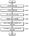
- FIG. 3 is a flowchart illustrating a method of forming an ultrasound image based on a PRF disable signal according to a second embodiment.
- the transceiver 120 provided in the high intensity focused ultrasound therapy apparatus 100 transmits a diagnostic ultrasound to an object and receives an ultrasound echo signal reflected from the object to form a received signal (S310).
- the ultrasound generator 122 provided in the high intensity focused ultrasound therapy apparatus 100 transmits the high intensity ultrasound to a specific region of the object (S320).
- the ultrasonic generator 122 provided in the high intensity focused ultrasound treatment apparatus 100 generates a PRF disable signal when transmitting the high intensity ultrasound and transmits the generated PRF disable signal to the transceiver 120 or the controller 140 (S330).
- the control unit 140 provided in the high intensity focused ultrasound therapy apparatus 100 may allow the transceiver 120 to switch the transmission of the diagnostic ultrasound to the disabled state while the PRF disable signal is received from the ultrasound generator 122.
- Control (S340).
- the ultrasound generator 122 provided in the high intensity focused ultrasound treatment apparatus 100 stops the transmission of the high intensity ultrasound when there is a command to stop the high intensity ultrasound through the user input unit 110, and the controller 140 generates the ultrasound generator. While the PRF disable signal is not received from the 122, the transceiver 120 controls the transmission of the diagnostic ultrasound to be enabled (S350).
- Transmitting and receiving unit 120 provided in the high-intensity focused ultrasound therapy apparatus 100 when receiving the ultrasound echo signal corresponding to the diagnostic ultrasound transmitted to the object, the transition period and enable to the disabled state according to the PRF disable signal And receiving the third ultrasonic echo signal reflecting the period to the state to form the third received signal.
- the image processor 160 of the high intensity focused ultrasound therapy apparatus 100 forms a B-mode (or C-mode) image from which interference by the high intensity ultrasound is removed based on the third received signal.
- a mode (or C-mode) image is output through the display unit 170 provided with the image.
- steps S310 to S360 are described as being sequentially executed. However, this is merely illustrative of the technical idea of the present embodiment, and a person having ordinary knowledge in the technical field to which the present embodiment belongs may use the present embodiment. 3 may be modified and modified by changing the order described in FIG. 3 or executing one or more steps of steps S310 to S360 in parallel without departing from the essential characteristics thereof. It is not limited.
- the method of forming an ultrasound image based on the PRF disable signal according to the second embodiment of FIG. 3 may be implemented by a program and recorded on a computer-readable recording medium.
- a program for realizing a method of forming an ultrasound image based on a PRF disable signal according to the second embodiment is recorded, and a computer-readable recording medium records all kinds of data in which data that can be read by a computer system is stored.
- Examples of such computer-readable recording media include ROM, RAM, CD-ROM, magnetic tape, floppy disk, optical data storage, and the like, and are implemented in the form of a carrier wave (for example, transmission over the Internet). It includes being.
- the computer readable recording medium can also be distributed over network coupled computer systems so that the computer readable code is stored and executed in a distributed fashion. Also, functional programs, codes, and code segments for implementing the present embodiment may be easily inferred by programmers in the art to which the present embodiment belongs.
- FIG. 4 is an exemplary view of forming an ultrasound image based on a PRF setting value and a duty for the high intensity ultrasound according to the first embodiment.
- 'Treatment Module' illustrated in FIG. 4 corresponds to the ultrasonic generator 122 in the present embodiment
- 'Imaging Module' refers to the present embodiment.
- the transmission / reception unit 120, the image processing unit 160, and the display unit 170 correspond to each other.
- 'Treatment Module' and 'Imaging Module' may operate under the control of the controller 140 according to the present embodiment.
- the controller 140 sets a PRF set value or a preset duty of the high intensity ultrasound in the 'Treatment Module' and the 'Imaging Module' based on the information input by the user input unit 110. This may be referred to as 'Set Desited HIFU PRF and Duty'.
- the 'Imaging Module' transmits the diagnostic ultrasound to the object and receives the ultrasound echo signal reflected from the object to form a received signal. Thereafter, the 'Imaging Module' transmits a trigger signal to the 'Treatment Module' based on the preset duty so that the 'Treatment Module' transmits the high intensity ultrasound. At this time, the 'Imaging Module' switches the transmission of the diagnostic ultrasound to the disabled state based on the preset duty. If the 'Treatment Module' stops the transmission of the high intensity ultrasound based on the preset duty, the 'Imaging Module' converts the transmission of the diagnostic ultrasound to the enabled state.
- the 'Imaging Module' transmits a trigger signal to the 'Treatment Module' based on the preset duty so that the 'Treatment Module' transmits the high intensity ultrasound.
- the 'Imaging Module' switches the transmission of the diagnostic ultrasound to the disabled state based on the preset duty. If the 'Treatment Module' stops the transmission of the high intensity ultrasound based on the preset duty, the 'Imaging Module' converts the transmission of the diagnostic ultrasound to the enabled state.
- the 'Imaging Module' receives an ultrasonic echo signal corresponding to the diagnostic ultrasound transmitted to the object, but includes a second transition period in which the transition to the disable state and the enable state for the diagnostic ultrasound are reflected.
- the ultrasonic echo signal is received to form a second received signal.
- the 'Imaging Module' forms a B-mode (or C-mode) image from which interference by high-intensity ultrasound is removed based on the second received signal, and displays a B-mode (or C-mode) image. It is operated to output through the unit 170.
- FIG. 5 illustrates an example of forming an ultrasound image based on a PRF disable signal according to a second embodiment.
- 'Treatment Module' illustrated in FIG. 5 corresponds to the ultrasonic wave generator 122 in the present embodiment
- 'Imaging Module' refers to the present embodiment.
- the transmission / reception unit 120, the image processing unit 160, and the display unit 170 correspond to each other.
- 'Treatment Module' and 'Imaging Module' may operate under the control of the controller 140 according to the present embodiment.
- the 'Imaging Module' forms a received signal by transmitting diagnostic ultrasound to the object and receiving an ultrasound echo signal reflected from the object.
- the PRF disable signal is transmitted to the 'imagining module'.
- 'Imaging Module' disables the transmission of diagnostic ultrasound when the PRF disable signal is received from the 'Treatment Module' and enables the transmission of diagnostic ultrasound when the transmission of the PRF disable signal from the 'Treatment Module' is stopped. .
- the 'Imaging Module' receives an ultrasonic echo signal corresponding to the diagnostic ultrasound transmitted to the object, but reflects the switching cycle to the disabled state and the cycle to the enabled state according to the PRF disable signal.
- the third ultrasonic echo signal is received to form a third received signal.
- the 'Imaging Module' forms a B-mode (or C-mode) image from which interference by high-intensity ultrasound is eliminated based on the third received signal, and displays a B-mode (or C-mode) image. It is operated to output through the unit 170.
- FIG. 6 is an exemplary view showing an image from which interference is removed according to the present embodiment.
- the case of the ultrasound echo signal in which the transition period to the disabled state and the cycle to the enabled state is not reflected for the diagnostic ultrasound is referred to as 'Imaging Module'.
- the diagnostic ultrasound is transmitted, and an ultrasound echo signal that does not reflect the switching cycle to the disabled state and the cycle to the enabled state is received to form a reception signal.
- the 'Imaging Module' forms a B-mode (or C-mode) image from which interference by high-intensity ultrasound is removed based on the received signal, and includes a display unit having a B-mode (or C-mode) image (
- the generated image may cause interference, such as a hatching portion of FIG. 4. Due to such interference shape, it is difficult to accurately identify the image during high-intensity focused ultrasound therapy.
- the 'Imaging Module' receives an ultrasound echo signal corresponding to the diagnostic ultrasound transmitted to the object, but switches to the disabled state for the diagnostic ultrasound and enables the ultrasound.
- the second ultrasonic echo signal reflecting the cycle of the furnace is received to form a second received signal.
- the 'Imaging Module' forms a B-mode (or C-mode) image from which interference by high-intensity ultrasound is removed based on the second received signal, and displays a B-mode (or C-mode) image. It is operated to output through the unit 170. That is, since the removed B-mode (or C-mode) image is formed, it can be accurately confirmed in the corresponding image during the high intensity focused ultrasound treatment.
- Figure 6 (b) receives an ultrasound echo signal corresponding to the diagnostic ultrasound transmitted to the object in the 'Imaging Module', the transition period to the disabled state and the cycle to enable state according to the PRF disable signal Receives the reflected third ultrasonic echo signal to form a third received signal.
- the 'Imaging Module' forms a B-mode (or C-mode) image from which interference by high-intensity ultrasound is eliminated based on the third received signal, and displays a B-mode (or C-mode) image. It is operated to output through the unit 170. That is, since the removed B-mode (or C-mode) image is formed, it can be accurately confirmed in the corresponding image during the high intensity focused ultrasound treatment.
Landscapes
- Health & Medical Sciences (AREA)
- Life Sciences & Earth Sciences (AREA)
- Engineering & Computer Science (AREA)
- Veterinary Medicine (AREA)
- Nuclear Medicine, Radiotherapy & Molecular Imaging (AREA)
- Public Health (AREA)
- Biomedical Technology (AREA)
- General Health & Medical Sciences (AREA)
- Animal Behavior & Ethology (AREA)
- Radiology & Medical Imaging (AREA)
- Surgery (AREA)
- Medical Informatics (AREA)
- Molecular Biology (AREA)
- Physics & Mathematics (AREA)
- Heart & Thoracic Surgery (AREA)
- Pathology (AREA)
- Biophysics (AREA)
- Computer Vision & Pattern Recognition (AREA)
- Plasma & Fusion (AREA)
- Otolaryngology (AREA)
- Ultra Sonic Daignosis Equipment (AREA)
- Surgical Instruments (AREA)
Abstract
Description
Claims (24)
- 대상체로 진단용 초음파를 송신하고 상기 대상체로부터 반사되는 초음파 에코 신호를 수신하여 수신 신호를 형성하도록 동작하는 송수신부;상기 수신 신호에 기초하여 B-모드 영상이 형성되도록 하며, 상기 B-모드 영상이 구비된 디스플레이부를 통해 출력하도록 동작하는 영상 처리부;상기 대상체의 특정 영역으로 고강도 초음파를 송신하는 초음파 발생부; 및상기 고강도 초음파에 대한 PRF(Pelse Repetition Frequency) 설정값, 기 설정된 듀티(Duty) 및 상기 초음파 발생부를 통해 생성되는 PRF 디세이블 신호 중 적어도 하나 이상의 정보에 근거하여 상기 송수신부와 상기 초음파 발생부로 하여금, 상기 진단용 초음파와 상기 고강도 초음파의 송신 주기를 제어하도록 하는 제어부를 포함하는 것을 특징으로 하는 고강도 집속 초음파 치료 장치.
- 제 1 항에 있어서,상기 제어부는,상기 PRF 설정값과 상기 기 설정된 듀티에 근거하여 상기 초음파 발생부에서 상기 고강도 초음파의 송신 주기가 도래하기 전까지 상기 송수신부로 하여금 상기 진단용 초음파의 송신을 이네이블(Enable) 상태를 유지하도록 제어하는 것을 특징으로 하는 고강도 집속 초음파 치료 장치.
- 제 2 항에 있어서,상기 제어부는,상기 초음파 발생부에서 상기 PRF 설정값에 해당하는 주기로 상기 기 설정된 듀티 만큼의 상기 고강도 초음파를 송신할 때, 상기 송수신부로 하여금 상기 PRF 설정값에 해당하는 주기로 상기 기설정된 듀티 동안 상기 진단용 초음파의 송신을 디세이블(Disable) 상태로 전환하도록 제어하는 것을 특징으로 하는 고강도 집속 초음파 치료 장치.
- 제 3 항에 있어서,상기 제어부는,상기 초음파 발생부에서 상기 기 설정된 듀티에 근거하여 상기 고강도 초음파의 송신이 중단되는 경우, 상기 송수신부로 하여금 상기 진단용 초음파의 송신이 상기 이네이블 상태로 전환되도록 제어하는 것을 특징으로 하는 고강도 집속 초음파 치료 장치.
- 제 4 항에 있어서,상기 송수신부는,상기 대상체로 송신된 상기 진단용 초음파에 대응하는 초음파 에코 신호를 수신하되, 상기 진단용 초음파에 대한 상기 디세이블 상태로의 전환 주기와 상기 이네이블 상태로의 주기가 반영된 상기 제 2 초음파 에코 신호를 수신하여 상기 제 2 수신 신호를 형성하도록 동작하는 것을 특징으로 하는 고강도 집속 초음파 치료 장치.
- 제 5 항에 있어서,상기 영상 처리부는,상기 제 2 수신 신호에 기초하여 상기 고강도 초음파에 의한 간섭이 제거된 상기 B-모드 영상이 형성되도록 하며, 상기 B-모드 영상이 구비된 상기 디스플레이부를 통해 출력하도록 동작하는 것을 특징으로 하는 고강도 집속 초음파 치료 장치.
- 제 3 항에 있어서,상기 제어부는,상기 기 설정된 듀티에 근거하여 상기 송수신부로 하여금 상기 진단용 초음파의 송신을 상기 디세이블 상태로 전환할 때, 상기 초음파 발생부로 트리거 신호를 전송하여 상기 초음파 발생부에서 상기 고강도 초음파를 송신하도록 하는 것을 특징으로 하는 고강도 집속 초음파 치료 장치.
- 제 1 항에 있어서,상기 초음파 발생부는 상기 고강도 초음파를 송신할 때 상기 PRF 디세이블 신호를 생성하여 상기 송수신부 또는 상기 제어부로 전송하며,상기 제어부는 상기 PRF 디세이블 신호가 수신되는 동안, 상기 송수신부로 하여금 상기 진단용 초음파의 송신을 디세이블 상태로 전환하도록 제어하는 것을 특징으로 하는 고강도 집속 초음파 치료 장치.
- 제 8 항에 있어서,상기 초음파 발생부는 상기 고강도 초음파의 송신이 중단된 경우, 상기 PRF 디세이블 신호의 전송을 중단하며,상기 제어부는 상기 PRF 디세이블 신호가 수신되지 않는 동안, 상기 송수신부로 하여금 상기 진단용 초음파의 송신이 이네이블 상태로 전환되도록 제어하는 것을 특징으로 하는 고강도 집속 초음파 치료 장치.
- 제 9 항에 있어서,상기 송수신부는,상기 대상체로 송신된 상기 진단용 초음파에 대응하는 초음파 에코 신호를 수신하되, 상기 PRF 디세이블 신호에 따른 상기 디세이블 상태로의 전환 주기와 상기 이네이블 상태로의 주기가 반영된 상기 제 3 초음파 에코 신호를 수신하여 상기 제 3 수신 신호를 형성하도록 동작하는 것을 특징으로 하는 고강도 집속 초음파 치료 장치.
- 제 10 항에 있어서,상기 영상 처리부는,상기 제 3 수신 신호에 기초하여 상기 고강도 초음파에 의한 간섭이 제거된 상기 B-모드 영상이 형성되도록 하며, 상기 B-모드 영상이 구비된 상기 디스플레이부를 통해 출력하도록 동작하는 것을 특징으로 하는 고강도 집속 초음파 치료 장치.
- 제 1 항에 있어서,상기 제어부는,구비된 사용자 입력부에 의해 입력된 정보에 근거하여 상기 PRF 설정값와 상기 기 설정된 듀티를 설정하는 것을 특징으로 하는 고강도 집속 초음파 치료 장치.
- 송수신부에서 대상체로 진단용 초음파를 송신하고 상기 대상체로부터 반사되는 초음파 에코 신호를 수신하여 수신 신호를 형성하도록 동작하는 송수신 과정;영상 처리부에서 상기 수신 신호에 기초하여 B-모드 영상이 형성되도록 하며, 상기 B-모드 영상이 구비된 디스플레이부를 통해 출력하도록 동작하는 영상 처리 과정;초음파 발생부에서 상기 대상체의 특정 영역으로 고강도 초음파를 송신하는 고강도 초음파 발생 과정; 및제어부에서 상기 고강도 초음파에 대한 PRF 설정값, 기 설정된 듀티 및 상기 초음파 발생부를 통해 생성되는 PRF 디세이블 신호 중 적어도 하나 이상의 정보에 근거하여 상기 송수신부와 상기 초음파 발생부로 하여금, 상기 진단용 초음파와 상기 고강도 초음파의 송신 주기를 제어하도록 하는 제어 과정을 포함하는 것을 특징으로 하는 초음파 진단을 위한 송수신 신호를 이용한 초음파 영상 형성 방법.
- 제 13 항에 있어서,상기 제어 과정은,상기 제어부에서 상기 PRF 설정값과 상기 기 설정된 듀티에 근거하여 상기 초음파 발생부에서 상기 고강도 초음파의 송신 주기가 도래하기 전까지 상기 송수신부로 하여금 상기 진단용 초음파의 송신을 이네이블 상태를 유지하도록 제어하는 과정을 포함하는 것을 특징으로 하는 초음파 진단을 위한 송수신 신호를 이용한 초음파 영상 형성 방법.
- 제 14 항에 있어서,상기 제어 과정은,상기 초음파 발생부에서 상기 PRF 설정값에 해당하는 주기로 상기 기 설정된 듀티 만큼의 상기 고강도 초음파를 송신할 때, 상기 제어부가 상기 송수신부로 하여금 상기 PRF 설정값에 해당하는 주기로 상기 기설정된 듀티 동안 상기 진단용 초음파의 송신을 디세이블 상태로 전환하도록 제어하는 과정을 포함하는 것을 특징으로 하는 초음파 진단을 위한 송수신 신호를 이용한 초음파 영상 형성 방법.
- 제 15 항에 있어서,상기 제어 과정은,상기 초음파 발생부에서 상기 기 설정된 듀티에 근거하여 상기 고강도 초음파의 송신이 중단되는 경우, 상기 제어부가 상기 송수신부로 하여금 상기 진단용 초음파의 송신이 상기 이네이블 상태로 전환되도록 제어하는 과정을 포함하는 것을 특징으로 하는 초음파 진단을 위한 송수신 신호를 이용한 초음파 영상 형성 방법.
- 제 16 항에 있어서,상기 송수신 과정은,상기 송수신부에서 상기 대상체로 송신된 상기 진단용 초음파에 대응하는 초음파 에코 신호를 수신하되, 상기 진단용 초음파에 대한 상기 디세이블 상태로의 전환 주기와 상기 이네이블 상태로의 주기가 반영된 상기 제 2 초음파 에코 신호를 수신하여 상기 제 2 수신 신호를 형성하도록 동작하는 과정을 포함하는 것을 특징으로 하는 초음파 진단을 위한 송수신 신호를 이용한 초음파 영상 형성 방법.
- 제 17 항에 있어서,상기 영상 처리 과정은,상기 영상 처리부에서 상기 제 2 수신 신호에 기초하여 상기 고강도 초음파에 의한 간섭이 제거된 상기 B-모드 영상이 형성되도록 하며, 상기 B-모드 영상이 구비된 상기 디스플레이부를 통해 출력하도록 동작하는 과정을 포함하는 것을 특징으로 하는 초음파 진단을 위한 송수신 신호를 이용한 초음파 영상 형성 방법.
- 제 15 항에 있어서,상기 제어 과정은,상기 제어부에서 상기 기 설정된 듀티에 근거하여 상기 송수신부로 하여금 상기 진단용 초음파의 송신을 상기 디세이블 상태로 전환할 때, 상기 초음파 발생부로 트리거 신호를 전송하여 상기 초음파 발생부에서 상기 고강도 초음파를 송신하도록 하는 과정을 포함하는 것을 특징으로 하는 초음파 진단을 위한 송수신 신호를 이용한 초음파 영상 형성 방법.
- 제 13 항에 있어서,상기 제어 과정은,상기 초음파 발생부에서 상기 고강도 초음파를 송신할 때 상기 PRF 디세이블 신호를 생성하여 상기 송수신부 또는 상기 제어부로 전송하는 과정; 및상기 제어부에서 상기 PRF 디세이블 신호가 수신되는 동안, 상기 송수신부로 하여금 상기 진단용 초음파의 송신을 디세이블 상태로 전환하도록 제어하는 과정을 포함하는 것을 특징으로 하는 초음파 진단을 위한 송수신 신호를 이용한 초음파 영상 형성 방법.
- 제 20 항에 있어서,상기 제어 과정은,상기 초음파 발생부에서 상기 고강도 초음파의 송신이 중단된 경우, 상기 PRF 디세이블 신호의 전송을 중단하는 과정; 및상기 제어부에서 상기 PRF 디세이블 신호가 수신되지 않는 동안, 상기 송수신부로 하여금 상기 진단용 초음파의 송신이 이네이블 상태로 전환되도록 제어하는 과정을 포함하는 것을 특징으로 하는 초음파 진단을 위한 송수신 신호를 이용한 초음파 영상 형성 방법.
- 제 21 항에 있어서,상기 송수신부에서 상기 대상체로 송신된 상기 진단용 초음파에 대응하는 초음파 에코 신호를 수신하되, 상기 PRF 디세이블 신호에 따른 상기 디세이블 상태로의 전환 주기와 상기 이네이블 상태로의 주기가 반영된 상기 제 3 초음파 에코 신호를 수신하여 상기 제 3 수신 신호를 형성하도록 동작하는 과정을 추가로 포함하는 것을 특징으로 하는 초음파 진단을 위한 송수신 신호를 이용한 초음파 영상 형성 방법.
- 제 22 항에 있어서,상기 영상 처리부에서 상기 제 3 수신 신호에 기초하여 상기 고강도 초음파에 의한 간섭이 제거된 상기 B-모드 영상이 형성되도록 하며, 상기 B-모드 영상이 구비된 상기 디스플레이부를 통해 출력하도록 동작하는 과정을 추가로 포함하는 것을 특징으로 하는 초음파 진단을 위한 송수신 신호를 이용한 초음파 영상 형성 방법.
- 제 13 항에 있어서,구비된 사용자 입력부에 의해 입력된 정보에 근거하여 상기 PRF 설정값와 상기 기 설정된 듀티를 설정하는 과정을 추가로 포함하는 것을 특징으로 하는 초음파 진단을 위한 송수신 신호를 이용한 초음파 영상 형성 방법.
Priority Applications (6)
| Application Number | Priority Date | Filing Date | Title |
|---|---|---|---|
| CN201180076076.7A CN104039392A (zh) | 2011-12-29 | 2011-12-29 | 一种用于超声诊断的利用信号收发的超声成像方法及其高强度聚焦超声治疗装置 |
| JP2014549947A JP2015503967A (ja) | 2011-12-29 | 2011-12-29 | 超音波診断のための送受信信号を用いた超音波映像形成方法及びそのための高強度集束超音波治療装置 |
| PCT/KR2011/010334 WO2013100232A1 (ko) | 2011-12-29 | 2011-12-29 | 초음파 진단을 위한 송수신 신호를 이용한 초음파 영상 형성 방법과 그를 위한 고강도 집속 초음파 치료 장치 |
| KR1020147017522A KR101629701B1 (ko) | 2011-12-29 | 2011-12-29 | 초음파 진단을 위한 송수신 신호를 이용한 초음파 영상 형성 방법과 그를 위한 고강도 집속 초음파 치료 장치 |
| US14/369,568 US20150011880A1 (en) | 2011-12-29 | 2011-12-29 | Method using transmitted and received signals for forming ultrasonic images for ultrasonic diagnosis, and high-intensity focused ultrasonic therapeutic device performing the same |
| EP11879148.2A EP2799113A4 (en) | 2011-12-29 | 2011-12-29 | METHOD USING SIGNALS TRANSMITTED AND RECEIVED TO FORM ULTRASONIC IMAGES FOR ULTRASONIC DIAGNOSIS, AND HIGH INTENSITY FOCUSED ULTRASONIC THERAPEUTIC DEVICE PROVIDING THE SAME |
Applications Claiming Priority (1)
| Application Number | Priority Date | Filing Date | Title |
|---|---|---|---|
| PCT/KR2011/010334 WO2013100232A1 (ko) | 2011-12-29 | 2011-12-29 | 초음파 진단을 위한 송수신 신호를 이용한 초음파 영상 형성 방법과 그를 위한 고강도 집속 초음파 치료 장치 |
Publications (1)
| Publication Number | Publication Date |
|---|---|
| WO2013100232A1 true WO2013100232A1 (ko) | 2013-07-04 |
Family
ID=48697683
Family Applications (1)
| Application Number | Title | Priority Date | Filing Date |
|---|---|---|---|
| PCT/KR2011/010334 WO2013100232A1 (ko) | 2011-12-29 | 2011-12-29 | 초음파 진단을 위한 송수신 신호를 이용한 초음파 영상 형성 방법과 그를 위한 고강도 집속 초음파 치료 장치 |
Country Status (6)
| Country | Link |
|---|---|
| US (1) | US20150011880A1 (ko) |
| EP (1) | EP2799113A4 (ko) |
| JP (1) | JP2015503967A (ko) |
| KR (1) | KR101629701B1 (ko) |
| CN (1) | CN104039392A (ko) |
| WO (1) | WO2013100232A1 (ko) |
Cited By (1)
| Publication number | Priority date | Publication date | Assignee | Title |
|---|---|---|---|---|
| KR20220097734A (ko) * | 2020-12-31 | 2022-07-08 | (주)아이엠지티 | 집속 초음파 장치 및 초음파 신호 간 무간섭 방법 |
Families Citing this family (8)
| Publication number | Priority date | Publication date | Assignee | Title |
|---|---|---|---|---|
| CN106102584B (zh) | 2014-03-14 | 2019-06-21 | 爱飞纽医疗机械贸易有限公司 | 基于软件的超声波成像系统 |
| US10123782B2 (en) | 2014-07-07 | 2018-11-13 | The Board Of Trustees Of The Leland Stanford Junior University | Integrated system for ultrasound imaging and therapy using per-pixel switches |
| US20170281982A1 (en) * | 2016-03-31 | 2017-10-05 | Family Health International | Methods and systems for generating an occlusion using ultrasound |
| JP6780447B2 (ja) * | 2016-11-02 | 2020-11-04 | コニカミノルタ株式会社 | 超音波診断装置及び画像形成方法 |
| EP3923815A4 (en) * | 2019-02-12 | 2022-11-09 | The Board of Trustees of the Leland Stanford Junior University | SYSTEMS AND METHODS FOR FOCUSED HIGH INTENSITY ULTRASOUND |
| CN110433406B (zh) * | 2019-09-04 | 2021-05-28 | 珠海医凯电子科技有限公司 | 超声聚焦定位图像优化方法 |
| CN113332620B (zh) * | 2021-07-12 | 2023-03-14 | 重庆融海超声医学工程研究中心有限公司 | 一种超声医疗设备 |
| KR102700077B1 (ko) * | 2023-11-22 | 2024-08-29 | (주)아이엠지티 | 집속 초음파 장치 및 초음파 펄스 신호 간 무간섭 방법 |
Citations (5)
| Publication number | Priority date | Publication date | Assignee | Title |
|---|---|---|---|---|
| US5558092A (en) * | 1995-06-06 | 1996-09-24 | Imarx Pharmaceutical Corp. | Methods and apparatus for performing diagnostic and therapeutic ultrasound simultaneously |
| JP2008513148A (ja) * | 2004-09-16 | 2008-05-01 | ユニヴァーシティ オブ ワシントン | ソフトウェアツールを用いた、hifu治療中の無干渉超音波イメージング |
| KR20100120091A (ko) * | 2009-05-04 | 2010-11-12 | 지멘스 메디컬 솔루션즈 유에스에이, 인크. | 고강도 집속된 초음파를 위한 의료용 초음파 영상화에서의 피드백 |
| KR20100121277A (ko) * | 2009-05-08 | 2010-11-17 | 알피니언메디칼시스템 주식회사 | 초음파 치료기용 헤드, 초음파 치료기 및 초음파 치료기의 동작 방법 |
| KR20110076377A (ko) * | 2009-12-29 | 2011-07-06 | 서강대학교산학협력단 | 모델링을 이용한 하이푸 치료 장치, 그 방법 및 기록 매체 |
Family Cites Families (12)
| Publication number | Priority date | Publication date | Assignee | Title |
|---|---|---|---|---|
| US6425867B1 (en) * | 1998-09-18 | 2002-07-30 | University Of Washington | Noise-free real time ultrasonic imaging of a treatment site undergoing high intensity focused ultrasound therapy |
| US7520856B2 (en) * | 1999-09-17 | 2009-04-21 | University Of Washington | Image guided high intensity focused ultrasound device for therapy in obstetrics and gynecology |
| JP3863414B2 (ja) * | 2001-11-22 | 2006-12-27 | 株式会社東芝 | 超音波診断装置 |
| JP2006136441A (ja) * | 2004-11-11 | 2006-06-01 | Toshiba Corp | 超音波照射装置及び超音波照射方法 |
| US9198680B2 (en) * | 2005-08-30 | 2015-12-01 | Koninklijke Philips N.V. | Combination imaging and therapy transducer with therapy transducer amplifier |
| DE102005053918A1 (de) * | 2005-11-11 | 2007-05-16 | Zimmer Elektromedizin Gmbh | Verfahren und Vorrichtung zur Einstrahlung von Ultraschall in Gewebe |
| JP4958475B2 (ja) * | 2006-05-19 | 2012-06-20 | 株式会社日立メディコ | 超音波装置 |
| US20080021321A1 (en) * | 2006-05-22 | 2008-01-24 | Siemens Medical Solutions Usa, Inc. | Contrast agent destruction or therapy event indication in ultrasound medical imaging |
| US20080097207A1 (en) * | 2006-09-12 | 2008-04-24 | Siemens Medical Solutions Usa, Inc. | Ultrasound therapy monitoring with diagnostic ultrasound |
| US20080071173A1 (en) * | 2006-09-18 | 2008-03-20 | Aldrich William N | Visualizing Formation of Ablation Lesions |
| FR2935097A1 (fr) * | 2008-08-22 | 2010-02-26 | Theraclion | Dispositif de traitement therapeutique |
| BRPI1006245A2 (pt) * | 2009-04-15 | 2019-04-02 | Koninl Philips Electronics Nv | "dispositivo para o exercício do controle sobre o crescimento no tecido corporal" |
-
2011
- 2011-12-29 CN CN201180076076.7A patent/CN104039392A/zh active Pending
- 2011-12-29 KR KR1020147017522A patent/KR101629701B1/ko active IP Right Grant
- 2011-12-29 JP JP2014549947A patent/JP2015503967A/ja active Pending
- 2011-12-29 WO PCT/KR2011/010334 patent/WO2013100232A1/ko active Application Filing
- 2011-12-29 EP EP11879148.2A patent/EP2799113A4/en not_active Withdrawn
- 2011-12-29 US US14/369,568 patent/US20150011880A1/en not_active Abandoned
Patent Citations (5)
| Publication number | Priority date | Publication date | Assignee | Title |
|---|---|---|---|---|
| US5558092A (en) * | 1995-06-06 | 1996-09-24 | Imarx Pharmaceutical Corp. | Methods and apparatus for performing diagnostic and therapeutic ultrasound simultaneously |
| JP2008513148A (ja) * | 2004-09-16 | 2008-05-01 | ユニヴァーシティ オブ ワシントン | ソフトウェアツールを用いた、hifu治療中の無干渉超音波イメージング |
| KR20100120091A (ko) * | 2009-05-04 | 2010-11-12 | 지멘스 메디컬 솔루션즈 유에스에이, 인크. | 고강도 집속된 초음파를 위한 의료용 초음파 영상화에서의 피드백 |
| KR20100121277A (ko) * | 2009-05-08 | 2010-11-17 | 알피니언메디칼시스템 주식회사 | 초음파 치료기용 헤드, 초음파 치료기 및 초음파 치료기의 동작 방법 |
| KR20110076377A (ko) * | 2009-12-29 | 2011-07-06 | 서강대학교산학협력단 | 모델링을 이용한 하이푸 치료 장치, 그 방법 및 기록 매체 |
Non-Patent Citations (1)
| Title |
|---|
| See also references of EP2799113A4 * |
Cited By (2)
| Publication number | Priority date | Publication date | Assignee | Title |
|---|---|---|---|---|
| KR20220097734A (ko) * | 2020-12-31 | 2022-07-08 | (주)아이엠지티 | 집속 초음파 장치 및 초음파 신호 간 무간섭 방법 |
| KR102549574B1 (ko) * | 2020-12-31 | 2023-06-30 | (주)아이엠지티 | 집속 초음파 장치 및 초음파 신호 간 무간섭 방법 |
Also Published As
| Publication number | Publication date |
|---|---|
| CN104039392A (zh) | 2014-09-10 |
| EP2799113A4 (en) | 2015-11-11 |
| JP2015503967A (ja) | 2015-02-05 |
| KR101629701B1 (ko) | 2016-06-14 |
| EP2799113A1 (en) | 2014-11-05 |
| US20150011880A1 (en) | 2015-01-08 |
| KR20140108238A (ko) | 2014-09-05 |
Similar Documents
| Publication | Publication Date | Title |
|---|---|---|
| WO2013100232A1 (ko) | 초음파 진단을 위한 송수신 신호를 이용한 초음파 영상 형성 방법과 그를 위한 고강도 집속 초음파 치료 장치 | |
| WO2019225840A1 (ko) | 체외 충격파 치료 장치 | |
| EP3199973A1 (en) | Subject information processing apparatus using acoustic waves received from the subject | |
| WO2014133208A1 (ko) | 초점 보상 방법과 그를 위한 초음파 의료 장치 | |
| JP2012519557A (ja) | 超音波処置撮像用アプリケータ | |
| CN1342057A (zh) | 超声波治疗装置 | |
| WO2014133209A1 (ko) | 캐비테이션 검출 방법과 그를 위한 초음파 의료 장치 | |
| CN103123721B (zh) | 一种实时减少图像中伪影的方法以及装置 | |
| CN104383646A (zh) | 一种超声介入治疗系统 | |
| WO2012096443A2 (ko) | 주파수 변화를 이용한 고강도 집속 초음파 제어 방법과 그를 위한 고강도 집속 초음파 치료 장치 | |
| WO2013047960A1 (ko) | 하이푸 초점 영상을 얻기 위한 초음파 영상 시스템 및 이를 이용한 초음파 영상 생성 방법 | |
| JP2001327495A (ja) | 超音波装置 | |
| CN106037804A (zh) | 一种脑部病变区域的定位系统 | |
| JP2023156101A (ja) | 超音波診断装置、超音波診断装置の制御方法、及び、超音波診断装置の制御プログラム | |
| KR20230100686A (ko) | 치료 및 이미징 동시 수행방법 및 이를 위한 다기능 초음파 프로브 | |
| WO2012141517A2 (ko) | 움직임 추적을 이용한 초음파 치료 장치와 그를 위한 방법 | |
| WO2014014133A1 (ko) | 복수의 주파수를 이용한 고강도 집속 초음파 제어 방법과 그를 위한 고강도 집속 초음파 치료 장치 | |
| WO2020082269A1 (zh) | 一种成像方法以及成像系统 | |
| CN112971842A (zh) | 一种超声诊断设备低功耗控制的方法及装置 | |
| JP2006192031A (ja) | 超音波画像診断装置 | |
| US11083914B2 (en) | Ultrasonic treatment device | |
| JP7137682B1 (ja) | 超音波治療装置 | |
| JP7170359B1 (ja) | 超音波画像処理装置 | |
| JP2009125383A (ja) | 超音波治療診断装置 | |
| WO2013100246A1 (ko) | 가변 인덕터를 이용한 초음파 진단 방법 및 장치 |
Legal Events
| Date | Code | Title | Description |
|---|---|---|---|
| 121 | Ep: the epo has been informed by wipo that ep was designated in this application |
Ref document number: 11879148 Country of ref document: EP Kind code of ref document: A1 |
|
| ENP | Entry into the national phase |
Ref document number: 20147017522 Country of ref document: KR Kind code of ref document: A |
|
| ENP | Entry into the national phase |
Ref document number: 2014549947 Country of ref document: JP Kind code of ref document: A |
|
| WWE | Wipo information: entry into national phase |
Ref document number: 14369568 Country of ref document: US |
|
| NENP | Non-entry into the national phase |
Ref country code: DE |
|
| REEP | Request for entry into the european phase |
Ref document number: 2011879148 Country of ref document: EP |
|
| WWE | Wipo information: entry into national phase |
Ref document number: 2011879148 Country of ref document: EP |