WO2013099397A1 - Nebulizer and nebulizer kit - Google Patents
Nebulizer and nebulizer kit Download PDFInfo
- Publication number
- WO2013099397A1 WO2013099397A1 PCT/JP2012/076115 JP2012076115W WO2013099397A1 WO 2013099397 A1 WO2013099397 A1 WO 2013099397A1 JP 2012076115 W JP2012076115 W JP 2012076115W WO 2013099397 A1 WO2013099397 A1 WO 2013099397A1
- Authority
- WO
- WIPO (PCT)
- Prior art keywords
- compressed air
- forming body
- see
- path forming
- liquid
- Prior art date
Links
Images


Classifications
-
- A—HUMAN NECESSITIES
- A61—MEDICAL OR VETERINARY SCIENCE; HYGIENE
- A61M—DEVICES FOR INTRODUCING MEDIA INTO, OR ONTO, THE BODY; DEVICES FOR TRANSDUCING BODY MEDIA OR FOR TAKING MEDIA FROM THE BODY; DEVICES FOR PRODUCING OR ENDING SLEEP OR STUPOR
- A61M11/00—Sprayers or atomisers specially adapted for therapeutic purposes
- A61M11/02—Sprayers or atomisers specially adapted for therapeutic purposes operated by air or other gas pressure applied to the liquid or other product to be sprayed or atomised
-
- B—PERFORMING OPERATIONS; TRANSPORTING
- B05—SPRAYING OR ATOMISING IN GENERAL; APPLYING FLUENT MATERIALS TO SURFACES, IN GENERAL
- B05B—SPRAYING APPARATUS; ATOMISING APPARATUS; NOZZLES
- B05B7/00—Spraying apparatus for discharge of liquids or other fluent materials from two or more sources, e.g. of liquid and air, of powder and gas
- B05B7/24—Spraying apparatus for discharge of liquids or other fluent materials from two or more sources, e.g. of liquid and air, of powder and gas with means, e.g. a container, for supplying liquid or other fluent material to a discharge device
- B05B7/2402—Apparatus to be carried on or by a person, e.g. by hand; Apparatus comprising containers fixed to the discharge device
- B05B7/2405—Apparatus to be carried on or by a person, e.g. by hand; Apparatus comprising containers fixed to the discharge device using an atomising fluid as carrying fluid for feeding, e.g. by suction or pressure, a carried liquid from the container to the nozzle
- B05B7/2429—Apparatus to be carried on or by a person, e.g. by hand; Apparatus comprising containers fixed to the discharge device using an atomising fluid as carrying fluid for feeding, e.g. by suction or pressure, a carried liquid from the container to the nozzle the carried liquid and the main stream of atomising fluid being brought together after discharge
-
- A—HUMAN NECESSITIES
- A61—MEDICAL OR VETERINARY SCIENCE; HYGIENE
- A61M—DEVICES FOR INTRODUCING MEDIA INTO, OR ONTO, THE BODY; DEVICES FOR TRANSDUCING BODY MEDIA OR FOR TAKING MEDIA FROM THE BODY; DEVICES FOR PRODUCING OR ENDING SLEEP OR STUPOR
- A61M11/00—Sprayers or atomisers specially adapted for therapeutic purposes
- A61M11/001—Particle size control
- A61M11/002—Particle size control by flow deviation causing inertial separation of transported particles
-
- A—HUMAN NECESSITIES
- A61—MEDICAL OR VETERINARY SCIENCE; HYGIENE
- A61M—DEVICES FOR INTRODUCING MEDIA INTO, OR ONTO, THE BODY; DEVICES FOR TRANSDUCING BODY MEDIA OR FOR TAKING MEDIA FROM THE BODY; DEVICES FOR PRODUCING OR ENDING SLEEP OR STUPOR
- A61M11/00—Sprayers or atomisers specially adapted for therapeutic purposes
- A61M11/06—Sprayers or atomisers specially adapted for therapeutic purposes of the injector type
-
- B—PERFORMING OPERATIONS; TRANSPORTING
- B05—SPRAYING OR ATOMISING IN GENERAL; APPLYING FLUENT MATERIALS TO SURFACES, IN GENERAL
- B05B—SPRAYING APPARATUS; ATOMISING APPARATUS; NOZZLES
- B05B7/00—Spraying apparatus for discharge of liquids or other fluent materials from two or more sources, e.g. of liquid and air, of powder and gas
- B05B7/0012—Apparatus for achieving spraying before discharge from the apparatus
-
- B—PERFORMING OPERATIONS; TRANSPORTING
- B05—SPRAYING OR ATOMISING IN GENERAL; APPLYING FLUENT MATERIALS TO SURFACES, IN GENERAL
- B05B—SPRAYING APPARATUS; ATOMISING APPARATUS; NOZZLES
- B05B7/00—Spraying apparatus for discharge of liquids or other fluent materials from two or more sources, e.g. of liquid and air, of powder and gas
- B05B7/02—Spray pistols; Apparatus for discharge
- B05B7/06—Spray pistols; Apparatus for discharge with at least one outlet orifice surrounding another approximately in the same plane
- B05B7/062—Spray pistols; Apparatus for discharge with at least one outlet orifice surrounding another approximately in the same plane with only one liquid outlet and at least one gas outlet
- B05B7/063—Spray pistols; Apparatus for discharge with at least one outlet orifice surrounding another approximately in the same plane with only one liquid outlet and at least one gas outlet one fluid being sucked by the other
- B05B7/064—Spray pistols; Apparatus for discharge with at least one outlet orifice surrounding another approximately in the same plane with only one liquid outlet and at least one gas outlet one fluid being sucked by the other the liquid being sucked by the gas
-
- A—HUMAN NECESSITIES
- A61—MEDICAL OR VETERINARY SCIENCE; HYGIENE
- A61M—DEVICES FOR INTRODUCING MEDIA INTO, OR ONTO, THE BODY; DEVICES FOR TRANSDUCING BODY MEDIA OR FOR TAKING MEDIA FROM THE BODY; DEVICES FOR PRODUCING OR ENDING SLEEP OR STUPOR
- A61M2206/00—Characteristics of a physical parameter; associated device therefor
- A61M2206/10—Flow characteristics
- A61M2206/14—Static flow deviators in tubes disturbing laminar flow in tubes, e.g. archimedes screws
-
- A—HUMAN NECESSITIES
- A61—MEDICAL OR VETERINARY SCIENCE; HYGIENE
- A61M—DEVICES FOR INTRODUCING MEDIA INTO, OR ONTO, THE BODY; DEVICES FOR TRANSDUCING BODY MEDIA OR FOR TAKING MEDIA FROM THE BODY; DEVICES FOR PRODUCING OR ENDING SLEEP OR STUPOR
- A61M2209/00—Ancillary equipment
- A61M2209/06—Packaging for specific medical equipment
-
- A—HUMAN NECESSITIES
- A61—MEDICAL OR VETERINARY SCIENCE; HYGIENE
- A61M—DEVICES FOR INTRODUCING MEDIA INTO, OR ONTO, THE BODY; DEVICES FOR TRANSDUCING BODY MEDIA OR FOR TAKING MEDIA FROM THE BODY; DEVICES FOR PRODUCING OR ENDING SLEEP OR STUPOR
- A61M2209/00—Ancillary equipment
- A61M2209/10—Equipment for cleaning
Definitions
- the present invention relates to a nebulizer and a nebulizer kit.
- Nebulizers generate aerosols by atomizing chemicals that treat diseases such as water, saline, bronchi, or liquids such as vaccines.
- a typical nebulizer includes a nebulizer kit that generates an aerosol.
- Patent Document 1 Japanese Patent Laid-Open No. 06-285168 is known as a document disclosing a nebulizer kit.
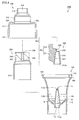
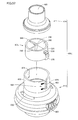
- FIG. 60 is a cross-sectional view showing the nebulizer kit 1000Z.
- the nebulizer kit 1000Z includes a case body 900, an atomization part forming body 920, a flow path forming body 930, and an atomization part M.
- the case body 900 is formed in a bottomed cylindrical shape.
- An upper opening 902 is provided in the upper part of the case body 900.
- a compressed air introduction pipe 913 and a liquid storage portion 916 are provided inside the case body 900.
- the compressed air introduction pipe 913 extends from the bottom surface (liquid storage unit 916) side of the case body 900 toward the upper side. Compressed air (not shown) is introduced into the compressed air introduction pipe 913.
- a nozzle hole 915 for ejecting compressed air is provided at the upper end 913a of the compressed air introduction pipe 913.
- the liquid storage part 916 for storing the liquid W is provided on the lower side of the compressed air introduction pipe 913 so as to surround the outer peripheral surface of the compressed air introduction pipe 913.
- the atomization part forming body 920 includes a liquid absorption pipe forming part 924, a baffle part 922, and a baffle support part 923.
- the liquid absorption pipe forming part 924 is formed in a cylindrical shape.
- the diameter of the liquid suction pipe forming portion 924 decreases as it goes from the lower side to the upper side.
- An opening 924 a is provided at the top of the liquid suction pipe forming part 924.
- the baffle portion 922 has a protrusion 925 positioned directly above the opening 924a.
- the protrusion 925 is provided as necessary.
- the baffle support part 923 extends from the outer surface of the liquid suction pipe forming part 924 toward the side part of the baffle part 922.
- the baffle portion 922 and the protrusion 925 are opposed to the opening portion 924a with a space therebetween.
- the atomization part forming body 920 is accommodated and arranged inside the case body 900 such that the outer surface of the compressed air introduction pipe 913 is covered with the liquid absorption pipe forming part 924.
- the flow path forming body 930 is attached to the case body 900 so as to close the upper opening 902 of the case body 900.
- the flow path forming body 930 includes an aerosol discharge port 932 and an outside air introduction tube 934.
- the aerosol discharge port 932 is provided in the upper part of the flow path forming body 930.
- the aerosol generated inside the case body 900 (atomization part M) is discharged to the outside through the aerosol discharge port 932.
- the outside air introduction pipe 934 is provided so as to penetrate the flow path forming body 930 from the upper side to the lower side.
- the outside air used for the generation of the aerosol is introduced from the outside of the case body 900 toward the inside of the case body 900 (atomization part M) through the outside air introduction tube 934.
- FIG. 61 is an enlarged cross-sectional view showing the atomizing portion M in the nebulizer kit 1000Z.
- the atomization part M is formed between the baffle part 922 (protrusion 925) provided in the atomization part forming body 920 and the nozzle hole 915 (see FIG. 60) provided in the compressed air introduction pipe 913.
- Compressed air introduced into the compressed air introduction pipe 913 is ejected through a nozzle hole 915 provided in the upper end portion 913a (see arrow AR913).
- the compressed air is ejected from the nozzle hole 915 toward the protrusion 925, and then collides with the protrusion 925 and the baffle portion 922, and the direction is changed to spread radially (see arrow AR922).
- the negative pressure which is a state lower than the surrounding pressure generate
- the liquid W is sucked up from the liquid storage part 916 to the vicinity of the atomization part M by the effect
- the liquid W is pulverized by collision with the compressed air flowing in the direction of the arrow AR922, and changes to mist-like particles (fine droplets) (not shown).
- the mist particles are added to the outside air (see arrow AR934) introduced into the case body 900 through the outside air introduction tube 934.
- aerosol is produced
- the aerosol is swung toward the aerosol discharge port 932 (see FIG. 60) (see arrow AR932) and discharged outside through the aerosol discharge port 932 (see FIG. 60).
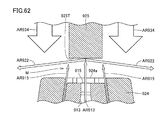
- FIG. 62 is a cross-sectional view further showing the atomizing portion M in the nebulizer kit 1000Z.
- the compressed air see arrow AR913
- the baffle portion 922 see FIG. 61
- the compressed air that collides with the lower end 925T of the protrusion 925 changes its direction and spreads radially (see arrow AR922).
- Compressed air pulverizes the liquid W by air pressure (wind pressure) and then collides with the inner peripheral surface of the baffle support portion 923 (see FIG. 61) or the outside air introduction pipe 934 (see FIG. 61).
- the compressed air that has become the aerosol moves toward the aerosol discharge port 932 (see FIG. 60) in a swirling manner (see the arrow AR932 in FIG. 61), and passes outside through the aerosol discharge port 932 (see FIG. 60). Discharged.
- the compressed air ejected from the nozzle hole 915 first collides with the protrusion 925 (and / or the baffle portion 922), and then collides with the baffle support portion 923 (see FIG. 61). Then, it further collides with the inner peripheral surface of the outside air introduction pipe 934 (see FIG. 61). The compressed air ejected from the nozzle hole 915 loses pressure at each collision.
- Compressed air introduced into the compressed air introduction pipe 913 needs to be prepared in advance with sufficient pressure necessary for generating the nebulizer after allowing for pressure loss. Therefore, in a conventional nebulizer kit such as the nebulizer kit 1000Z, it is necessary to use a compressor having a large capacity (flow rate) and a large size in order to generate compressed air having a large flow rate.
- the present invention has been made in view of the above circumstances, and it is an object of the present invention to provide a nebulizer kit and a nebulizer capable of reducing loss of compressed air pressure when an aerosol is generated.
- a nebulizer kit includes a compressed air introduction pipe extending upward, into which compressed air is introduced, and having a nozzle hole for ejecting the compressed air formed at an upper tip, and the compressed air
- a compressed air introduction pipe extending upward, into which compressed air is introduced, and having a nozzle hole for ejecting the compressed air formed at an upper tip
- the compressed air By covering the outer peripheral surface of the compressed air introduction pipe with the case body opened on the upper side including the liquid storage portion provided so as to surround the outer peripheral surface of the compressed air introduction pipe on the lower side of the introduction pipe Forming a suction path for sucking up the liquid stored in the liquid storage part toward the upper tip of the compressed air introduction pipe, and mist in the outlet area of the nozzle hole provided in the compressed air introduction pipe
- the liquid suction port is located on the opening region of the nozzle hole.
- the nozzle hole is circular, and the center line of the nozzle hole is located on the surface including the liquid suction port.
- a liquid reservoir portion having a larger channel cross-sectional area than the second wicking path is provided in an intersection region between the first wicking path and the second wicking path.
- the liquid suction port has an opening shape extending in the lateral direction.
- the nozzle hole is defined by a cylindrical inner peripheral surface, and the inner peripheral surface is a tapered surface whose diameter increases toward the outside.
- a nebulizer based on the present invention includes a main body having a compressor for sending out compressed air, a compressed air pipe part to which compressed air sent from the compressor is introduced, and one end of the compressed air pipe part connected to each other to generate an aerosol.
- a nebulizer kit according to the invention includes a main body having a compressor for sending out compressed air, a compressed air pipe part to which compressed air sent from the compressor is introduced, and one end of the compressed air pipe part connected to each other to generate an aerosol.
- a nebulizer kit and a nebulizer capable of reducing loss of compressed air pressure when aerosol is generated.
- FIG. 1 is a perspective view showing a nebulizer in Embodiment 1.
- FIG. 1 is a perspective view showing a nebulizer kit in Embodiment 1.
- FIG. 3 is a perspective view showing an exploded state of the nebulizer kit in the first embodiment. 3 is a cross-sectional view showing a disassembled state of the nebulizer kit according to Embodiment 1.
- FIG. 5 is a cross-sectional view taken along line VV in FIG. 2.
- FIG. 3 is a first perspective view showing a suction channel forming body used in the nebulizer kit in the first embodiment.
- FIG. 7 is a cross-sectional perspective view taken along the line VII-VII in FIG.
- FIG. 6 is a first cross-sectional perspective view showing a suction path forming body used in the nebulizer kit in the first embodiment.
- FIG. 6 is a second perspective view showing a suction channel forming body used in the nebulizer kit in the first embodiment.
- FIG. 9 is a cross-sectional perspective view taken along the line IX-IX in FIG. 8 and is a second cross-sectional perspective view showing a suction channel forming body used in the nebulizer kit in the first embodiment. It is a cross-sectional perspective view which shows the state by which the suction path formation body used for the nebulizer kit in Embodiment 1 was accommodated and arrange
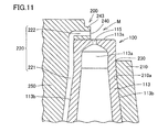
- FIG. 11 is a cross-sectional view taken along line XI-XI in FIG. 10.
- 3 is a perspective view showing a particle sorting unit used in the nebulizer kit according to Embodiment 1.
- FIG. FIG. 3 is a cross-sectional view showing an atomization portion and its vicinity when aerosol is formed by the nebulizer kit in the first embodiment.
- 2 is a cross-sectional view showing an overall state of the nebulizer kit when an aerosol is formed by the nebulizer kit in Embodiment 1.
- FIG. FIG. 6 is a cross-sectional view showing an atomizing portion of the nebulizer kit in the second embodiment and its vicinity.
- FIG. 6 is a cross-sectional view showing an atomizing portion of a nebulizer kit in the third embodiment and its vicinity. It is a perspective view which shows the atomization part of the nebulizer kit in Embodiment 4, and its vicinity. It is a perspective view which shows the atomization part of the nebulizer kit in Embodiment 5, and its vicinity. It is a perspective view which shows the atomization part of the nebulizer kit in Embodiment 6, and its vicinity. It is sectional drawing which shows the atomization part of the nebulizer kit in Embodiment 7, and its vicinity. It is a perspective view which shows the atomization part of the nebulizer kit in Embodiment 8, and its vicinity.
- FIG. It is a perspective view which shows the atomization part of the nebulizer kit in Embodiment 9, and its vicinity. It is a perspective view which shows the wicking path
- FIG. It is sectional drawing which shows the atomization part of the nebulizer kit in Embodiment 10, and its vicinity. It is a perspective view which shows the atomization part of the nebulizer kit in Embodiment 11, and its vicinity. It is a perspective view which shows a mode when the suction path formation body of the nebulizer kit in Embodiment 11 is attached to a case body (compressed air introduction pipe
- FIG. 28 is a cross-sectional view taken along the line XXVIII-XXVIII in FIG. It is sectional drawing which shows typically a mode when an aerosol is produced
- FIG. It is a perspective view which shows the atomization part of the nebulizer kit in Embodiment 13, and its vicinity. It is the top view seen from the arrow XXI direction in FIG.
- FIG. 31 is a cross-sectional view taken along the line XXXII-XXXII in FIG. 30.
- FIG. 34 is a cross-sectional view taken along the line XXXIV-XXXIV in FIG. 33. It is a perspective view which shows the atomization part of the nebulizer kit in Embodiment 15, and its vicinity.
- FIG. 36 is a cross-sectional view taken along the line XXXVI-XXXVI in FIG.
- FIG. 38 is a perspective view showing a particle sorting unit used in the nebulizer kit in the sixteenth embodiment.
- FIG. 38 is a cross-sectional perspective view showing a particle sorting portion used in the nebulizer kit in the sixteenth embodiment.
- FIG. 38 is a perspective view showing an exploded state of a particle sorting unit and a flow path forming body used in the nebulizer kit in the seventeenth embodiment.
- FIG. 40 is a cross-sectional view taken along line XL-XL in FIG. 39.
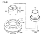
- FIG. 38 is a perspective view showing a state where a particle sorting unit and a flow path forming body used in the nebulizer kit in the eighteenth embodiment are disassembled.
- FIG. 38 is a perspective view showing a state where a particle sorting unit and a flow path forming body used in the nebulizer kit in the nineteenth embodiment are disassembled.
- FIG. 40 is a cross-sectional view taken along line XL-XL in FIG. 39.
- FIG. 38 is a perspective view showing a state where a particle sorting unit and a flow path forming body used in the nebulizer kit in the eighteenth embodiment are disassembled.
- FIG. 38 is a perspective view
- FIG. 38 is a perspective view showing a state where a particle sorting unit and a flow path forming body used in the nebulizer kit in the twentieth embodiment are disassembled.
- FIG. 38 is a perspective view showing a state where a particle sorting unit and a flow path forming body used in the nebulizer kit in Embodiment 21 are disassembled.
- FIG. 38 is a perspective view showing a nebulizer kit in a twenty-second embodiment.
- FIG. 38 is a perspective view showing an exploded state of a nebulizer kit in a twenty-second embodiment.
- FIG. 38 is a cross-sectional perspective view showing a case body and a suction path forming body used in a nebulizer kit in a twenty-second embodiment.
- FIG. 38 is a perspective view showing an upper cylindrical part of a flow path forming body used for a nebulizer kit in a twenty-second embodiment.
- FIG. 38 is a cross-sectional perspective view showing a state when a particle sorting portion used in a nebulizer kit in Embodiment 22 is fixed to an upper cylindrical portion of a flow path forming body.
- FIG. 38 is a cross-sectional perspective view showing a state when a particle sorting portion used in a nebulizer kit in Embodiment 22 is fixed to a lower cylindrical portion of a flow path forming body.
- FIG. 38 is a perspective view showing the operation of the nebulizer kit in the twenty-second embodiment.
- FIG. 38 is a first plan view showing a particle sorting portion and a flow path forming body used in the nebulizer kit in the twenty-second embodiment.
- FIG. 38 is a second plan view showing a particle sorting portion and a flow path forming body used in the nebulizer kit in the twenty-second embodiment.
- FIG. 38 is a third plan view showing a particle sorting portion and a flow path forming body used for the nebulizer kit in the twenty-second embodiment.
- FIG. 38 is a perspective view showing a disassembled state of a particle sorting section and a flow path forming body used in a nebulizer kit in a twenty-third embodiment.
- FIG. 38 is a cross-sectional perspective view showing a particle sorting portion used for a nebulizer kit in a twenty-third embodiment.
- FIG. 38 is a perspective view showing a state in which a particle sorting unit and a flow path forming body used in the nebulizer kit in Embodiment 24 are disassembled.
- FIG. 38 is a perspective view showing a state in which a particle sorting unit and a flow path forming body used in the nebulizer kit in Embodiment 25 are disassembled.
- FIG. 26 is a cross-sectional perspective view showing a particle sorting portion used for a nebulizer kit in a twenty-fifth embodiment. It is sectional drawing which shows a common nebulizer kit. It is sectional drawing which expands and shows the atomization part in a common nebulizer kit. It is sectional drawing which expands and shows the atomization part in a common nebulizer kit further.
- the nebulizer 2000 includes a main body 510, a tube 512 (compressed air pipe section), a nebulizer kit 1000, and a mouthpiece 500.
- the main body 510 incorporates a compressor that sends out compressed air, electronic components, and the like.
- the tube 512 has flexibility. One end of the tube 512 is connected to a compressed air blowing port 511 provided in the main body 510. The other end of the tube 512 is connected to the nebulizer kit 1000.
- the mouthpiece 500 is attached to the aerosol outlet 420 (see FIG. 2) of the nebulizer kit 1000.
- the mouthpiece 500 is used for suction to the nose or mouth by the user.
- the mouthpiece 500 is formed in a tubular shape, for example, as shown in FIG.
- the mouthpiece 500 may be formed in a mask shape.
- the mouthpiece 500 is a so-called disposable type, and is discarded after use from the viewpoint of hygiene.
- the nebulizer kit 1000 When the nebulizer kit 1000 is used, as shown in FIG. 1, the nebulizer kit 1000 is held by the user so that the longitudinal direction of the nebulizer kit 1000 is substantially parallel to the vertical direction.
- the upper and lower portions in the nebulizer kit 1000 correspond to an upper portion in the vertical direction and a lower portion in the vertical direction as viewed from the nebulizer kit 1000 in this use state (basic posture when the nebulizer kit 1000 is used).
- FIG. 2 is a perspective view showing the nebulizer kit 1000.
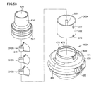
- FIG. 3 is a perspective view showing the nebulizer kit 1000 in an exploded state.
- FIG. 4 is a cross-sectional view showing the nebulizer kit 1000 in an exploded state.
- FIG. 5 is a cross-sectional view taken along line VV in FIG. 2 to 5, a nebulizer kit 1000 includes a case body 100, a suction channel forming body 200 (see FIGS. 3 to 5), a particle sorting unit 300 (see FIGS. 3 to 5), and a flow.
- a path forming body 400 is provided.
- the case body 100 includes a cylindrical portion 110, an opening 102 (upper opening), a compressed air introduction pipe 113, and a liquid storage portion 116, and is configured in a bottomed cylindrical shape as a whole. .
- the cylindrical part 110 is closed at the lower side by the liquid storage part 116 and is opened at the upper side where the opening 102 is provided.
- a fitting hole 180 is provided in the vicinity of the opening 102 of the cylindrical portion 110. In a state where the flow path forming body 400 is attached to the case body 100, the fitting hole 180 is fitted to the fitting convex portion 480 of the flow path forming body 400 (see FIGS. 2, 3, and 5). ).
- the compressed air introduction pipe 113 extends so as to reduce the diameter in a tapered shape from the lower center of the cylindrical portion 110 upward.
- a nozzle hole 115 is provided in the upper tip portion 113 a of the compressed air introduction tube 113.
- the nozzle hole 115 passes through substantially the center of the tip surface 113s of the upper tip portion 113a.
- a tube 512 (see FIG. 1) is attached to the lower end portion of the compressed air introduction tube 113.
- the compressor incorporated in the main body 510 (see FIG. 1) of the nebulizer 2000 introduces compressed air into the compressed air introduction pipe 113 through the compressed air blowing port 511 (see FIG. 1) and the tube 512 (see FIG. 1). .
- the compressed air introduced into the compressed air introduction pipe 113 is ejected from the nozzle hole 115 toward the inside of the case body 100.
- the liquid reservoir 116 is provided on the lower side of the compressed air introduction tube 113 so as to surround the outer peripheral surface 113b of the compressed air introduction tube 113.
- the liquid storage unit 116 temporarily stores a liquid W such as a chemical solution for curing diseases such as water, saline, and bronchi, or a vaccine.
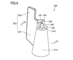
- FIG. 6 is a first perspective view showing the wicking path forming body 200, and shows the entire configuration of the wicking path forming body 200 as viewed obliquely from above.
- 7 is a cross-sectional perspective view taken along the line VII-VII in FIG. 6, and is a first perspective cross-sectional view showing the suction path forming body 200.
- FIG. 7 shows the internal structure of the wicking path forming body 200 as viewed obliquely from above.
- FIG. 8 is a second perspective view showing the wicking path forming body 200, and shows the entire configuration of the wicking path forming body 200 as viewed from obliquely below.
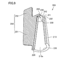
- FIG. 9 is a cross-sectional perspective view taken along the line IX-IX in FIG. 8 and is a second cross-sectional view showing the wicking path forming body 200.
- FIG. 9 shows the internal structure of the wicking path forming body 200 as viewed obliquely from below.
- the wicking path forming body 200 includes a cylindrical portion 210, a wicking path forming portion 220 (see FIGS. 7 to 9), an opening 230 (see FIGS. 6 and 7), An opening 235 (see FIGS. 8 and 9), a liquid suction port 240, and a plate-like gripping part 250 are provided.
- the cylindrical part 210 is formed in a cylindrical shape whose diameter is reduced in a tapered shape upward.
- An opening 230 is formed at the top of the cylindrical portion 210.
- An opening 235 is formed at the bottom of the cylindrical portion 210.
- the shape of the inner peripheral surface 210a of the cylindrical portion 210 corresponds to the shape of the outer peripheral surface 113b of the compressed air introduction tube 113 provided in the case body 100 (see FIG. 5).
- a bulging portion 241 formed in a half-column shape is provided on the upper end surface 232 of the cylindrical portion 210.
- a liquid suction port forming body 243 protruding in a columnar shape is provided on the end surface 242 of the bulging portion 241.
- the liquid suction port forming body 243 protrudes in a direction perpendicular to the end surface 242.
- the plate-like gripping portion 250 is provided so as to extend from the outer surface of the tubular portion 210 toward the outer side in the normal direction of the tubular portion 210.
- the plate-like gripping part 250 includes a plate part 251 and a convex part 252.
- the convex portion 252 is provided integrally with the plate portion 251 above the plate portion 251, and protrudes further upward than the height position of the top surface of the bulging portion 241.
- the suction channel forming part 220 is formed in a substantially L shape as a whole.
- the suction path forming portion 220 is recessed on the inner peripheral surface 210a of the tubular portion 210 so as to extend substantially linearly from the opening 235 side toward the opening 230 side, and the bulging portion 241.
- the liquid suction port forming body 243 is provided so as to penetrate the inside.
- the tip in the extending direction of the suction channel forming part 220 penetrating the liquid suction port forming body 243 reaches the surface of the liquid suction port forming body 243.
- a liquid suction port 240 is formed at the tip portion of the suction path forming portion 220 that reaches the surface of the liquid suction port forming body 243.
- the diameter of the liquid suction port 240 is, for example, not less than 0.45 mm and not more than 0.5 mm.
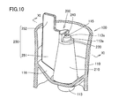
- FIG. 10 is a cross-sectional perspective view showing a state in which the suction path forming body 200 is accommodated and arranged inside the case body 100.
- 11 is a cross-sectional view taken along the line XI-XI in FIG.
- the air suction path forming body 200 is accommodated and arranged inside the case body 100 such that the outer peripheral surface 113 b of the compressed air introduction pipe 113 is covered with the cylindrical portion 210.
- the nozzle hole 115 and the liquid suction port 240 are arranged such that the center line of the nozzle hole 115 and the center line of the liquid suction port 240 are substantially orthogonal to each other.
- the inner peripheral surface 210a of the cylindrical portion 210 and the outer peripheral surface 113b of the compressed air introduction tube 113 are substantially the same except for the portion where the suction path forming portion 220 is provided on the inner peripheral surface 210a of the cylindrical portion 210. It is in close contact.
- a suction channel 221 (first suction channel) is formed between the suction channel forming part 220 and the outer peripheral surface 113b of the compressed air introduction pipe 113.
- the suction path 221 extends upward along the outer peripheral surface 113b of the compressed air introduction pipe 113 from the liquid reservoir 116 (see FIG. 10) side toward the nozzle hole 115 side.
- a wicking path 222 (second wicking path) is formed so as to be continuous with the upper end of the wicking path 221.
- the wicking path 222 extends in a direction orthogonal to the tip of the wicking path 221.
- the suction path 222 extends on the distal end side of the compressed air introduction pipe 113 from the distal end of the suction path 221 toward the nozzle hole 115 in a direction substantially orthogonal to the central axis direction of the nozzle hole 115.
- a liquid suction port 240 is formed at the tip portion of the suction channel 222. In the present embodiment, the liquid suction port 240 does not overlap the nozzle hole 115 but is disposed at a position slightly retracted with respect to the nozzle hole 115.
- FIG. 12 is a perspective view showing the particle sorting unit 300.
- the particle sorting unit 300 is configured in a substantially cylindrical shape that extends while decreasing in diameter from the lower side toward the upper side.
- the particle sorting unit 300 includes a lower cylindrical part 310, an upper cylindrical part 320, a central shaft part 330, and four blade parts 340.
- the lower cylindrical portion 310 is disposed coaxially with the upper cylindrical portion 320.
- the diameter of the lower cylindrical portion 310 is larger than the diameter of the upper cylindrical portion 320.
- the four blade portions 340 are provided between the central shaft portion 330 located at the center of the upper cylindrical portion 320 and the inner peripheral surface of the upper cylindrical portion 320. Each of the four blade portions 340 is formed in a plate shape having substantially the same shape. Each of the four blade portions 340 are arranged so as to be spaced apart from each other by 90 °. Each of the four blade portions 340 is curved while turning from the lower side of the upper cylindrical portion 320 toward the upper side of the upper cylindrical portion 320. The four blade portions 340 are arranged in a so-called screw shape as a whole. Each of the four blade portions 340 shields the space between the atomizing portion M and the aerosol discharge port 420 in a fan shape.
- the particle sorting unit 300 is disposed above the wicking path forming body 200 disposed inside the case body 100.
- the lower end of the particle sorting unit 300 is in contact with the upper end of the convex portion 252 of the wicking path forming body 200.
- the upper cylindrical part 320 of the particle sorting part 300 is fixed inside the central cylindrical part 412 of the flow path forming body 400 described below (see FIG. 5).
- the particle selector 300 is positioned by fixing the flow path forming body 400 to the case body 100.
- the suction path forming body 200 is fixed to the case body 100 by the lower end of the positioned particle sorting part 300 and the upper end of the convex part 252 of the suction path forming body 200 coming into contact with each other.
- the fixing By the fixing, the vertical movement of the suction path forming body 200 with respect to the case body 100 is restricted.
- the flow path forming body 400 is attached to the case body 100 so as to cover the opening 102 of the case body 100.
- the flow path forming body 400 includes a lower cylindrical portion 410, a central cylindrical portion 412, an upper cylindrical portion 414, an aerosol discharge port 420, an outside air introduction port 430, and a fitting convex portion 480.
- the lower cylindrical portion 410, the central cylindrical portion 412, and the upper cylindrical portion 414 are arranged coaxially with each other.
- the diameter of the central cylindrical part 412 is larger than the diameter of the upper cylindrical part 414.
- the diameter of the lower cylindrical portion 410 is larger than the diameter of the central cylindrical portion 412.
- the flow path forming body 400 as a whole is configured in a substantially cylindrical shape that extends while decreasing in diameter from the lower side toward the upper side.
- the aerosol discharge port 420 is formed inside the upper cylindrical portion 414.
- the outside air introduction port 430 is provided at a portion where the lower tubular portion 410 and the central tubular portion 412 are connected to each other (see FIG. 3).
- the fitting convex portion 480 is provided in the vicinity of the lower end of the lower cylindrical portion 410. As described above, when the flow path forming body 400 is attached to the case body 100, the fitting convex portion 480 is fitted to the fitting hole 180 of the case body 100 (FIGS. 2, 3, and 3). 5).
- the upper cylindrical part 320 of the particle sorting part 300 is fixed inside the central cylindrical part 412 (see FIG. 5).
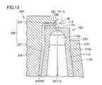
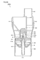
- FIG. 13 is a cross-sectional view showing the atomizing portion M and its vicinity when aerosol is formed by the nebulizer kit 1000 (see FIG. 2 and the like).
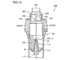
- FIG. 14 is a cross-sectional view showing the overall state of the nebulizer kit 1000 when aerosol is formed by the nebulizer kit 1000.
- the atomizing section M has an outlet region R115 of the nozzle hole 115 provided in the compressed air introduction pipe 113 (a central axis of the nozzle hole 115 provided in the compressed air introduction pipe 113 and a suction path formation). A region where the central axis of the liquid suction port 240 provided in the body 200 intersects) and its vicinity.
- Compressed air introduced into the compressed air introduction pipe 113 is ejected through a nozzle hole 115 provided in the upper tip 113a (see arrow AR113).
- a negative pressure that is lower than the surrounding pressure is generated in the atomizing portion M and in the vicinity thereof.
- the liquid W passes through the suction channel 221 and the suction channel 222 from the liquid storage unit 116 (see FIG. 14) to the vicinity of the atomization unit M by the action of the negative pressure generated in the atomization unit M and its vicinity. (See arrow AR220 in FIG. 13).
- the liquid W is gradually discharged from the liquid suction port 240 toward the atomizing portion M side.
- a small amount of the liquid W discharged from the liquid suction port 240 is pulverized by the collision with the compressed air flowing in the direction of the arrow AR113 in the atomizing portion M, and is changed into atomized particles (fine droplets) (not shown). .
- the mist particles are added to the outside air (see arrow AR430) introduced into the case body 100 through the outside air inlet 430.
- aerosol is produced
- the aerosol moves through the inside of the particle sorting unit 300 toward the aerosol discharge port 420.
- the blade portion 340 of the particle sorting unit 300 is disposed between the atomization unit M and the aerosol discharge port 420.
- those having a large particle diameter for example, 10 ⁇ m or more
- Aerosol having a desired particle size for example, 2 ⁇ m or more and less than 10 ⁇ m
- the aerosol is sucked into the user's nose or mouth through the mouthpiece 500 (see FIG. 1).
- the nebulizer kit 1000 When generating the aerosol having the same spray amount in the nebulizer kit 1000 and the nebulizer kit 1000Z, the nebulizer kit 1000 may be prepared with compressed air having a smaller flow rate than the nebulizer kit 1000Z.
- a compressor having a smaller capacity (flow rate) and a smaller size than the nebulizer kit 1000Z can be used. Therefore, the nebulizer kit 1000 can be manufactured not only at a low cost, but also can reduce the amount of energy required for generating aerosol.
- nebulizer kit 1000 individual parts can be easily cleaned by disassembling the individual parts.
- a plate-shaped gripping part 250 is provided on the suction path forming body 200. By using the plate-like gripping part 250 during cleaning, it is possible to prevent the suction path forming body 200 from being lost.
- the direction in which the suction channel 222 extends and the position where the liquid suction port 240 is provided are opposite to the direction in which the plate-like gripping portion 250 extends. It is.
- the spray of the aerosol generated in the atomizing part M is not hindered by the plate-shaped gripping part 250.
- the lower end of the particle sorting unit 300 comes into contact with the upper end of the convex portion 252 of the wicking path forming body 200 (see FIG. 5).
- the suction path forming body 200 is fixed (positioned) in the vertical direction with respect to the case body 100.
- the suction path forming body 200 is reliably prevented from being pushed up by the compressed air ejected from the nozzle hole 115.
- the aerosol can be continuously generated in the atomization part M.
- the suction path formation body 200 is not fixed in the rotational direction with respect to the case body 100, and the suction path formation body 200 is around the compressed air introduction pipe 113 with respect to the case body 100. You may comprise so that it can rotate freely.
- the suction path forming body 200 rotates according to the weight of the plate-shaped gripping part 250 so that the plate-shaped gripping part 250 is positioned at the lowest position in the gravity direction.
- the lower end of the suction channel 221 can be always immersed in the liquid W stored in the liquid storage unit 116. Even when the nebulizer kit 1000 is tilted, the wicking path 221 can continuously suck up the liquid W.
- the particle sorting unit 300 is fixed to the flow path forming body 400 (central cylindrical portion 412).
- the particle sorting unit 300 is also removed together with the flow path forming body 400.
- the particle sorting unit 300 and the flow path forming body 400 in the nebulizer kit 1000 are highly convenient for disassembly and cleaning.
- a blade portion 340 is provided inside the upper cylindrical portion 320.
- the blade part 340 is located on one side (end part) in the longitudinal direction of the particle sorting part 300.
- the blade portion 340 can be easily cleaned.
- the particle sorting unit 300 is reduced in diameter from the lower cylindrical unit 310 toward the upper cylindrical unit 320.
- the particle sorting unit 300 can effectively sort particles.
- the particle sorting unit 300 is mainly intended to sort aerosol particles according to the particle size, but particles having a necessary particle size may be obtained without using the particle sorting unit 300.
- the nebulizer kit 1000 may be used with the particle sorting unit 300 removed.
- the nebulizer kit 1000 may be used in a state where
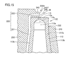
- the present embodiment will be described with reference to FIG.
- the nebulizer kit in the present embodiment includes a wicking path forming body 200A instead of the wicking path forming body 200 (see FIG. 13 and the like) in the first embodiment.
- the liquid suction port 240 in the suction path forming body 200 does not overlap the nozzle hole 115 but is disposed at a position slightly retracted from the nozzle hole 115.
- the suction channel formation body 200 ⁇ / b> A when the nozzle hole 115 is viewed from the liquid suction port 240, the liquid suction port 240 is located on the opening region of the nozzle hole 115.
- the position of the liquid suction port 240 is closer to the nozzle hole 115 in the suction path forming body 200A than in the suction path forming body 200 (see FIG. 13 and the like).
- the suction path forming body 200A is more likely to generate a negative pressure in the atomizing section M than the suction path forming body 200 (see FIG. 13 and the like). Therefore, compared to the suction path formation body 200 (see FIG. 13 and the like), the suction path formation body 200A can reduce the amount of compressed air introduced into the compressed air introduction pipe 113.
- the center line 115c of the nozzle hole 115 is positioned in a planar shape including the liquid suction port 240. May be.
- the front end portion 243T of the liquid suction port forming body 243 and the center line 115c of the nozzle hole 115 are located on the same plane.
- the position of the liquid suction port 240 with respect to the nozzle hole 115 (the distance between the liquid suction port 240 and the nozzle hole 115) is set in the compressed air introduction tube 113 so that the aerosol is generated more efficiently in the atomizing section M. It may be optimized according to the air volume of the compressed air to be introduced. According to the experimental results, when the amount of compressed air is relatively large, more aerosol is sprayed when the nozzle hole 115 is more than half exposed. On the other hand, when the amount of compressed air is relatively small, more aerosol is sprayed when the nozzle hole 115 is exposed about half.
- the nebulizer kit in the present embodiment includes a wicking path forming body 200B instead of the wicking path forming body 200A (see FIG. 15 and the like) in the second embodiment.
- a liquid reservoir 260 having a larger channel cross-sectional area than the suction channel 222 is provided in a region where the suction channel 221 and the suction channel 222 intersect (intersection region).
- the liquid W sucked up by the negative pressure action passes through the suction path 221 and then reaches the liquid reservoir 260.
- the liquid W is once stored in the liquid reservoir 260 and then discharged from the liquid suction port 240 through the suction passage 222.
- the liquid W can be discharged from the liquid suction port 240 continuously and stably without interruption.
- the nebulizer kit in the present embodiment includes a wicking path forming body 200C instead of the wicking path forming body 200 (see FIG. 10 and the like) in the first embodiment described above.
- the liquid suction port 240 is formed in an oval shape.
- the liquid suction port 240 has an opening shape extending in a direction (lateral direction) parallel to the tip surface 113 s of the compressed air introduction tube 113.
- the opening shape of the liquid suction port 240 may be formed so as to intersect at right angles to the central axis of the nozzle hole 115.
- the liquid W sucked up by the negative pressure action is discharged from the liquid suction port 240.
- the liquid W discharged from the liquid suction port 240 contacts the compressed air ejected from the nozzle hole 115 in a state where a thin liquid film is formed by spreading in the lateral direction.
- a small amount of liquid W in a liquid film gradually comes into contact with the compressed air ejected from the nozzle hole 115. Since the liquid W is easily pulverized by the compressed air ejected from the nozzle hole 115, the spray efficiency can be improved.
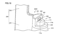
- the present embodiment will be described with reference to FIG.
- the nebulizer kit in the present embodiment includes a wicking path forming body 200D instead of the wicking path forming body 200 (see FIG. 10 and the like) in the first embodiment.
- a plurality of liquid suction ports 240 are provided in the suction path forming body 200D.
- the plurality of liquid suction ports 240 are arranged so as to be aligned in a direction (lateral direction) parallel to the tip surface 113 s of the compressed air introduction tube 113.
- the plurality of liquid suction ports 240 may be arranged so as to intersect at right angles to the central axis of the nozzle hole 115.
- the liquid W sucked up by the negative pressure action is discharged from each of the plurality of liquid suction ports 240.
- the amount of the liquid W ejected from each liquid suction port 240 is smaller than that in the case of the suction path forming body 200 in the first embodiment.
- a small amount of liquid W discharged from each liquid suction port 240 comes into contact with compressed air ejected from the nozzle hole 115.
- each liquid suction port 240 gradually contacts the compressed air ejected from the nozzle hole 115. Since the liquid W is easily pulverized by the compressed air ejected from the nozzle hole 115, the spray efficiency can be improved.
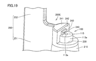
- the present embodiment will be described with reference to FIG.
- the nebulizer kit in the present embodiment includes a wicking path forming body 200E instead of the wicking path forming body 200 (see FIG. 10 and the like) in the first embodiment.
- the liquid suction port 240 is formed in a W shape.
- the liquid W sucked up by the negative pressure is gradually discharged from a narrow portion at the lower end of the liquid suction port 240.
- the amount of the liquid W discharged from the liquid suction port 240 is smaller than that in the case of the suction path forming body 200 in the first embodiment described above.
- a very small amount of liquid W discharged from the liquid suction port 240 comes into contact with compressed air ejected from the nozzle hole 115.
- a small amount of liquid W discharged from the liquid suction port 240 gradually comes into contact with the compressed air ejected from the nozzle hole 115. Since the liquid W is easily pulverized by the compressed air ejected from the nozzle hole 115, the spray efficiency can be improved. Even when the liquid suction port 240 is formed in a V shape or an M shape, the same operation and effect as in the present embodiment can be obtained.
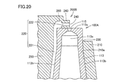
- the nebulizer kit in the present embodiment includes a case body 100A instead of the case body 100 (see FIG. 16 and the like) in the above-described third embodiment.
- the configuration of the case body 100A described below includes the above-described first embodiment (see FIG. 10), second embodiment (see FIG. 15), fourth embodiment (see FIG. 17), and fifth embodiment (see FIG. 18). ) And Embodiment 6 (see FIG. 19).
- the nozzle hole 115 defined by the cylindrical inner peripheral surface is composed of a tapered surface that expands toward the outside.
- the diameter of the nozzle hole 115 gradually increases along the flow direction of the compressed air.
- the nebulizer kit in the present embodiment includes a case body 100B instead of the case body 100 (see FIG. 10 and the like) in the above-described first embodiment.
- the configuration of the case body 100B described below includes the above-described second embodiment (see FIG. 15), third embodiment (see FIG. 16), fourth embodiment (see FIG. 17), and fifth embodiment (see FIG. 18). ) And Embodiment 6 (see FIG. 19).
- the nozzle hole 115 is formed in an oval shape.
- the nozzle hole 115 has an opening shape extending in a direction (lateral direction) orthogonal to the central axis direction of the liquid suction port 240 (the suction path 222 in FIG. 11).
- the compressed air is ejected from the nozzle hole 115 in a plate shape (cuboid shape) by spreading in the lateral direction.
- the liquid W sucked up by the negative pressure action is discharged from the liquid suction port 240.
- the liquid W discharged from the liquid suction port 240 is in contact with the compressed air that is ejected in a substantially rectangular parallelepiped shape.
- the liquid W contacts the compressed air over a wide area. Since the liquid W is easily pulverized by the compressed air ejected from the nozzle hole 115, the spray efficiency can be improved.
- the nebulizer kit in the present embodiment includes a case body 100C instead of the case body 100 (see FIG. 10 and the like) in the above-described first embodiment.
- the configuration of the case body 100C described below includes the above-described second embodiment (see FIG. 15), third embodiment (see FIG. 16), fourth embodiment (see FIG. 17), and fifth embodiment (see FIG. 18). ) And Embodiment 6 (see FIG. 19).
- a plurality of nozzle holes 115 are provided in the case body 100C.
- the plurality of nozzle holes 115 are arranged so as to be aligned in a direction (lateral direction) orthogonal to the central axis direction of the liquid suction port 240 (the suction path 222 in FIG. 11).
- the liquid W sucked up by the negative pressure action is discharged from the liquid suction port 240.
- the liquid W ejected from the liquid suction port 240 comes into contact with the compressed air ejected from each of the plurality of nozzle holes 115.
- the liquid W contacts the compressed air over a wide area. Since the liquid W is easily pulverized by the compressed air ejected from the nozzle hole 115, the spray efficiency can be improved.
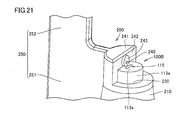
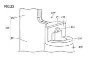
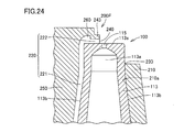
- FIG. 10 This embodiment will be described with reference to FIGS. 23 and 24.
- FIG. The nebulizer kit in the present embodiment includes a wicking path forming body 200F instead of the wicking path forming body 200 (see FIGS. 6, 7 and the like) in the first embodiment.
- the structure of the suction path forming body 200F described below is the same as that of the second embodiment (see FIG. 15), the third embodiment (see FIG. 16), the fourth embodiment (see FIG. 17), and the fifth embodiment (see FIG. 15). 18), Embodiment 6 (see FIG. 19), Embodiment 7 (see FIG. 20), Embodiment 8 (see FIG. 21), and Embodiment 9 (see FIG. 22). be able to.
- the wicking path forming portion 220 in the wicking path forming body 200 (see FIGS. 6, 7, etc.) of the first embodiment described above is formed on the inner peripheral surface 210 a of the cylindrical portion 210 from the opening 235 side through the opening 230.
- the concave portion is provided so as to extend substantially linearly toward the side, and is provided so as to penetrate the inside of the bulging portion 241 and the liquid suction port forming body 243.
- the suction path forming portion 220 in the suction path forming body 200F of the present embodiment is recessed in a groove shape as a whole and penetrates the liquid suction port forming body 243. Is not configured as such.
- the liquid suction port forming body 243 is formed in a U shape.
- the suction path forming body 200F is also accommodated and arranged inside the case body 100 such that the outer peripheral surface 113b of the compressed air introduction tube 113 is covered by the cylindrical portion 210.
- the suction path 221 is formed along the outer peripheral surface 113 b of the compressed air introduction pipe 113.
- the suction path 222 is formed along the tip surface 113 s of the compressed air introduction tube 113. Also with the suction path forming body 200F, the same operation and effect as in the first embodiment can be obtained.
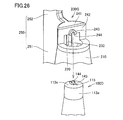
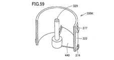
- FIG. 11 This embodiment will be described with reference to FIGS. 25 and 26.
- FIG. The nebulizer kit in the present embodiment includes a suction path forming body 200G instead of the suction path forming body 200 (see FIG. 6, FIG. 7, etc.) in the above-described first embodiment, and in the above-described first embodiment.
- a case body 100D is provided instead of the case body 100 (see FIG. 10 and the like).
- the wicking path forming part 220 (see FIG. 26) as a whole is a groove like the wicking path forming body 200F (see FIGS. 23 and 24) of the tenth embodiment described above. And is not configured to penetrate the liquid suction port forming body 243.
- the liquid suction port forming body 243 is formed in a U shape.
- a base 143 having a recess 144 is provided on the tip surface 113s of the upper tip 113a.
- the suction path forming body 200G is attached to the case body 100D (the compressed air introduction pipe 113).
- the pedestal 143 is fitted into the inner side 244 of the liquid suction port forming body 243.
- a liquid suction port 240 (see FIG. 25) is formed by the concave portion 144 of the base 143 and the inner side 244 of the liquid suction port forming body 243.
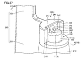
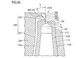
- FIG. 27 is a perspective view showing an atomizing portion of the nebulizer kit in the present embodiment and the vicinity thereof.
- 28 is a cross-sectional view taken along line XXVIII-XXVIII in FIG.
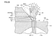
- FIG. 29 is a cross-sectional view schematically showing a state when aerosol is generated in the atomization portion of the nebulizer kit in the present embodiment.
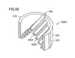
- the nebulizer kit in the present embodiment includes a wicking path forming body 200H instead of the wicking path forming body 200 (see FIGS. 6, 7 and the like) in the first embodiment described above.
- the structure of the suction path forming body 200H described below is the same as that of the second embodiment (see FIG. 15), the third embodiment (see FIG. 16), the fourth embodiment (see FIG. 17), and the fifth embodiment (see FIG. 15). 18), Embodiment 6 (see FIG. 19), Embodiment 7 (see FIG. 20), Embodiment 8 (see FIG. 21), and Embodiment 9 (see FIG. 22). be able to.
- the tip surface of the liquid suction port forming body 243 provided so as to protrude from the end surface 242 of the bulging portion 241 is inclined.
- an upper inclined surface region 270 that is inclined so as to be directed toward the suction path 221 as it goes upward is provided above the liquid suction port 240.
- the inclination angle ⁇ of the upper inclined surface region 270 with respect to the central axis of the nozzle hole 115 is set to 20 ° or more and 45 ° or less, for example. From the viewpoint of further improving the spray efficiency, the inclination angle ⁇ is set to 35 °.
- the tip end portion 243T of the liquid suction port forming body 243 is arranged along the inner peripheral end face of the nozzle hole 115 (in contact with the outer edge of the nozzle hole 115).
- the tip 243T may be arranged so as to coincide with the center line of the nozzle hole 115 (center line 115c in FIG. 15).
- two bulging portions 246 are provided on the end surface 242 of the bulging portion 241.
- the bulging portion 246 is disposed so as to sandwich the upper tip portion 113a from both outer sides of the upper tip portion 113a.
- the distal end surface of the bulging portion 246 and the distal end portion 243T of the liquid suction port forming body 243 are located on the same plane.
- the upper inclined surface region 270 is provided above the liquid suction port 240.
- the liquid suction port 240 and the upper inclined surface region 270 are inclined so as to gradually move away from the travel path of compressed air ejected from the nozzle hole 115 (see arrow AR113). Since the liquid suction port 240 is formed to be inclined (in other words, the liquid suction port 240 is formed so as to be gradually separated from the nozzle hole 115 as it goes upward), the degree of the inclination of the liquid suction port 240. It is possible to adjust the supply amount of the liquid W by increasing / decreasing.
- the supply amount of the liquid W can be reduced to an optimum value.
- the energy of the compressed air ejected from the nozzle hole 115 can be used for pulverizing the liquid W as much as possible.
- the liquid suction port 240 is formed to be inclined, the compressed air ejected from the nozzle hole 115 is also reliably prevented from entering the liquid suction port 240. Therefore, according to the wicking path forming body 200H, it is possible to further improve the energy use efficiency in atomizing the liquid W.
- an inclined surface 272 is also provided below the liquid suction port 240.
- the upper inclined surface region 270, the liquid suction port 240, and the inclined surface 272 are inclined in the same direction toward the nozzle hole 115.
- the liquid W discharged from the liquid suction port 240 becomes a droplet W1 and slides down on the inclined surface 272 (see arrow AR272).
- the droplet W1 gradually moves from the front side portion in the sliding-down direction to the upper region of the nozzle hole 115, and then contacts the compressed air. Due to the contact with the compressed air, the droplet W1 is crushed from the front portion in the sliding-down direction.
- the inclined surface 272 (a region located between the liquid suction port 240 and the nozzle hole 115 in the suction channel forming body 200) is inclined by the suction channel forming body 200H. It is preferable that the region 272 is more hydrophilic than the region where the surface 272 is provided. By reducing the size of the droplet W1, smaller particles can be obtained when the droplet W1 is pulverized. In order to increase the hydrophilicity of the inclined surface 272, a liquid rich in hydrophilicity may be applied to the inclined surface 272, or fine unevenness may be applied to the inclined surface 272.
- the aerosol W2 By providing the upper inclined surface region 270 above the liquid suction port 240, a large space is provided for the diffusion of the aerosol W2 generated by pulverizing the droplet W1. In a wider space (atomization part M), the aerosol W2 can be generated.
- the inclination angle ⁇ of the upper inclined surface region 270 with respect to the central axis of the nozzle hole 115 depends on the amount of compressed air introduced into the compressed air introduction pipe 113 so that the aerosol is generated more efficiently in the atomizing portion M. It should be optimized accordingly.
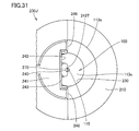
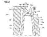
- FIG. 30 is a perspective view showing an atomizing portion of the nebulizer kit in the present embodiment and the vicinity thereof.
- FIG. 31 is a plan view showing the case body 100 and the like as seen from the direction of the arrow XXXI in FIG. 32 is a cross-sectional view taken along line XXXII-XXXII in FIG.
- the nebulizer kit in the present embodiment includes a wicking path forming body 200J instead of the wicking path forming body 200H (see FIG. 27 and the like) in the above-described twelfth embodiment.
- the configuration of the suction path forming body 200J described below is the same as that in the first embodiment (see FIG. 10), the second embodiment (see FIG. 15), the third embodiment (see FIG. 16), and the fourth embodiment (see FIG. 17), Embodiment 5 (see FIG. 18), Embodiment 6 (see FIG. 19), Embodiment 7 (see FIG. 20), Embodiment 8 (see FIG. 21), and Embodiment 9 (See FIG. 22).
- the lower inclined surface region that inclines toward the suction channel 221 (see FIG. 32) as it goes downward below the liquid suction port 240. 280 is provided.
- the lower end portion of the lower inclined surface region 280 is disposed so as to contact the outer edge of the nozzle hole 115.
- the tip 243T of the liquid suction port forming body 243 is located at a portion where the upper inclined surface region 270 and the lower inclined surface region 280 (see FIG. 32) intersect. Between the lower inclined surface region 280 and the liquid suction port 240, the inclined surface 272 (see FIG. 29) in the above-described Embodiment 12 may be further provided.
- the tip end portion 243 ⁇ / b> T of the liquid suction port forming body 243 is located at the center of the nozzle hole 115.
- the compressed air ejected from the nozzle hole 115 gradually changes its traveling direction along the lower inclined surface region 280 and spreads away from the liquid suction port 240.
- the compressed air ejected from the nozzle hole 115 is reliably suppressed from entering the liquid suction port 240. Therefore, according to the wicking path forming body 200J, the use efficiency of compressed air is high when generating an aerosol.
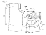
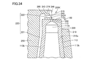
- FIG. 33 is a perspective view showing an atomizing portion of the nebulizer kit in the present embodiment and the vicinity thereof.
- 34 is a cross-sectional view taken along the line XXXIV-XXXIV in FIG.
- the nebulizer kit in the present embodiment includes a wicking path forming body 200K instead of the wicking path forming body 200J (see FIG. 30 and the like) in the thirteenth embodiment.
- the structure of the suction channel forming body 200K described below is the same as that of the first embodiment (see FIG. 10), the second embodiment (see FIG. 15), the third embodiment (see FIG. 16), and the fourth embodiment (see FIG. 10). 17), Embodiment 5 (see FIG. 18), Embodiment 6 (see FIG. 19), Embodiment 7 (see FIG. 20), Embodiment 8 (see FIG. 21), and Embodiment 9 (See FIG. 22).
- a convex portion 274 is provided on the surface of the upper inclined surface region 270.
- the convex part 274 has a rectangular parallelepiped shape.
- the protruding dimension of the convex portion 274 from the upper inclined surface region 270 is about 0.2 mm.
- the convex part 274 may be semispherical.
- the convex portion 274 is provided on the upper inclined surface region 270, whereby the value of the negative pressure generated in the atomizing portion M and the vicinity thereof can be increased (in other words, The pressure in the atomizing portion M and the vicinity thereof is lower than the surrounding pressure).
- the spray amount of aerosol can be increased.
- the inclination angle ⁇ (see FIG. 28) of the upper inclined surface region 270 with respect to the central axis of the nozzle hole 115 is set to 20 ° to 45 °, for example.
- the inclination angle ⁇ is larger than 45 ° (50 °, 60 °, etc.)
- the convex portion 274 is provided, the negative pressure is insufficient when the convex portion 274 is not provided. What has been difficult to absorb can be made to absorb liquid.
- the inclination angle ⁇ is set to 45 ° or less, it is possible to increase the amount of aerosol sprayed by providing the convex portion 274 (effective when the capacity of the compressor is low). .
- FIG. 35 is a perspective view showing an atomizing portion of the nebulizer kit and the vicinity thereof in the present embodiment.
- FIG. 36 is a cross-sectional view taken along line XXXVI-XXXVI in FIG.
- the nebulizer kit in the present embodiment includes a wicking path forming body 200L instead of the wicking path forming body 200J (see FIG. 30 and the like) in the above-described thirteenth embodiment.
- the configuration of the suction path forming body 200L described below is the same as that in the first embodiment (see FIG. 10), the second embodiment (see FIG. 15), the third embodiment (see FIG. 16), and the fourth embodiment (see FIG. 10). 17), Embodiment 5 (see FIG. 18), Embodiment 6 (see FIG. 19), Embodiment 7 (see FIG. 20), Embodiment 8 (see FIG. 21), and Embodiment 9 (See FIG. 22).
- the tip surface of the liquid suction port forming body 243 is formed to be curved in a convex shape.
- the upper inclined surface region 270 is curved in a convex shape, and the lower inclined surface region 280 is also curved in a convex shape.
- the liquid W discharged from the liquid suction port 240 is likely to spread over a wide range, and a liquid film is easily formed. Since the liquid W in which the liquid film has been formed is easily pulverized by the compressed air ejected from the nozzle hole 115, the spray efficiency can be improved.
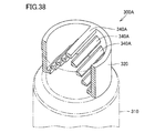
- FIG. 16 This embodiment will be described with reference to FIGS. 37 and 38.
- FIG. The nebulizer kit in the present embodiment includes a particle sorting unit 300A instead of the particle sorting unit 300 (see FIG. 3 and the like) in the first embodiment.
- the configuration of the particle sorting unit 300A described below can also be applied to the above second to fifteenth embodiments.
- each of the four blade sections 340 has a space between the atomizing section M (see FIG. 14 and the like) and the aerosol discharge port 420 (see FIG. 14 and the like). Shield like a fan.
- the particle sorting unit 300A in the present embodiment has a plurality of blade portions 340A.
- the plurality of blade portions 340 ⁇ / b> A are formed in a rod shape, and are arranged in a substantially triangular shape in sectional view from the lower cylindrical portion 310 side toward the upper cylindrical portion 320 side.
- the plurality of blade portions 340A are in a positional relationship parallel to each other (see FIG. 38).
- Each of the plurality of blade portions 340A shields the space between the atomizing portion M and the aerosol discharge port 420 in a linear manner.
- the particle sorting unit 300A Even in the case where the particle sorting unit 300A is used, among the aerosols moving from the atomizing unit M toward the aerosol discharge port 420, those having a large particle size (for example, 10 ⁇ m or more) adhere to the surface of the blade unit 340A. .
- the aerosol having a desired particle size (for example, 2 ⁇ m or more and less than 10 ⁇ m) selected by the blade portion 340A is discharged to the outside through the aerosol discharge port 420 (see FIG. 3 and the like). The aerosol is sucked into the user's nose or mouth through the mouthpiece 500 (see FIG. 1).
- FIG. The nebulizer kit in the present embodiment includes a particle sorting unit 300B instead of the particle sorting unit 300 (see FIG. 3 and the like) in the first embodiment, and instead of the flow path forming body 400 (see FIG. 3 and the like).
- a flow path forming body 400B is provided.
- the configurations of the particle sorting unit 300B and the flow path forming body 400B described below can also be applied to the above-described second to fifteenth embodiments.
- the upper tubular portion 414 and the lower tubular portion 410 of the flow path forming body 400B are configured separately from each other, and the particle sorting portion 300B is disposed on the inner side of the lower tubular portion 410. 410 is provided integrally.
- the upper cylindrical part 414 is fitted into the upper end of the upper cylindrical part 320 of the particle sorting part 300B.
- the aerosol that moves from the atomization unit M (see FIG. 14 and the like) toward the aerosol discharge port 420 has a large particle size (for example, 10 ⁇ m or more) and adheres to the surface of the blade portion 340. Aerosol having a desired particle size (for example, 2 ⁇ m or more and less than 10 ⁇ m) selected by the blade portion 340 is discharged to the outside through the aerosol discharge port 420. The aerosol is sucked into the user's nose or mouth through the mouthpiece 500 (see FIG. 1).
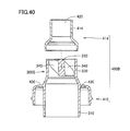
- the nebulizer kit in the present embodiment includes a particle sorting unit 300C instead of the particle sorting unit 300 (see FIG. 3 and the like) in the first embodiment, and instead of the flow path forming body 400 (see FIG. 3 and the like).
- a flow path forming body 400C is provided.
- the configurations of the particle sorting section 300C and the flow path forming body 400C described below can also be applied to the above second to fifteenth embodiments.
- the upper cylindrical portion 414 and the lower cylindrical portion 410 of the flow path forming body 400C are configured as separate bodies.
- the lower cylindrical portion 410 is provided with a cylindrical fixing portion 470.
- a step 472 is provided inside the cylindrical fixing portion 470.
- the cylindrical part 322 of the particle sorting part 300C is fitted inside the cylindrical fixing part 470.
- Four blade portions 340 are provided inside the cylindrical portion 322.
- the particle sorting section 300C is fixed to the flow path forming body 400C by being sandwiched between the upper cylindrical section 414 and the lower cylindrical section 410.
- the aerosol that moves from the atomization unit M (see FIG. 14 and the like) toward the aerosol discharge port 420 has a large particle size (for example, 10 ⁇ m or more) and adheres to the surface of the blade portion 340. Aerosol having a desired particle size (for example, 2 ⁇ m or more and less than 10 ⁇ m) selected by the blade portion 340 is discharged to the outside through the aerosol discharge port 420. The aerosol is sucked into the user's nose or mouth through the mouthpiece 500 (see FIG. 1).
- the nebulizer kit in the present embodiment includes a particle sorting unit 300D instead of the particle sorting unit 300 (see FIG. 3 and the like) in the above-described first embodiment, and instead of the flow path forming body 400 (see FIG. 3 and the like).
- a flow path forming body 400D is provided.
- the configurations of the particle sorting unit 300D and the flow path forming body 400D described below can also be applied to the above second to fifteenth embodiments.
- the upper cylindrical portion 414 and the lower cylindrical portion 410 of the flow path forming body 400D are configured as separate bodies.
- the lower cylindrical portion 410 is provided with a cylindrical fixing portion 470.
- a step 472 is provided inside the cylindrical fixing portion 470.
- the cylindrical portion 322 of the particle sorting portion 300D is fitted inside the cylindrical fixing portion 470.
- a plurality of blade portions 340 ⁇ / b> A are provided inside the tubular portion 322.
- the particle sorting section 300D is fixed to the flow path forming body 400D by being sandwiched between the upper cylindrical section 414 and the lower cylindrical section 410.
- the aerosol that moves from the atomizing unit M (see FIG. 14 and the like) toward the aerosol discharge port 420 has a large particle size (for example, 10 ⁇ m or more) and adheres to the surface of the blade portion 340A.
- Aerosol having a desired particle size (for example, 2 ⁇ m or more and less than 10 ⁇ m) selected by the blade portion 340 ⁇ / b> A is discharged to the outside through the aerosol discharge port 420. The aerosol is sucked into the user's nose or mouth through the mouthpiece 500 (see FIG. 1).
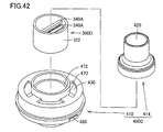
- the nebulizer kit in the present embodiment includes a particle sorting unit 300E instead of the particle sorting unit 300 (see FIG. 3 and the like) in the first embodiment, and instead of the flow path forming body 400 (see FIG. 3 and the like).
- a flow path forming body 400E is provided.
- the configurations of the particle sorting unit 300E and the flow path forming body 400E described below can also be applied to the above-described second to fifteenth embodiments.
- the upper cylindrical portion 414 and the lower cylindrical portion 410 of the flow path forming body 400E are configured as separate bodies.
- the lower cylindrical portion 410 is provided with a cylindrical fixing portion 470.
- a fitting recess 474 is provided inside the cylindrical fixing portion 470.
- the cylindrical part 322 of the particle sorting part 300E is fitted inside the cylindrical fixing part 470.
- Four blade portions 340 are provided inside the cylindrical portion 322.
- a fitting convex portion 374 is provided outside the tubular portion 322.
- the particle sorting part 300E is sandwiched between the upper cylindrical part 414 and the lower cylindrical part 410 in a state where the fitting convex part 374 and the fitting concave part 474 are fitted to each other, whereby a flow path forming body. Fixed to 400E.
- the aerosol that moves from the atomizing unit M (see FIG. 14 and the like) toward the aerosol discharge port 420 has a large particle size (for example, 10 ⁇ m or more) and adheres to the surface of the blade portion 340. Aerosol having a desired particle size (for example, 2 ⁇ m or more and less than 10 ⁇ m) selected by the blade portion 340 is discharged to the outside through the aerosol discharge port 420. Since the particle sorting unit 300E is restricted from moving in the rotational direction with respect to the flow path forming body 400E, an aerosol having a particle diameter closer to the design value is discharged to the outside. The aerosol is sucked into the user's nose or mouth through the mouthpiece 500 (see FIG. 1).
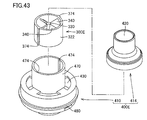
- the present embodiment will be described with reference to FIG.
- the nebulizer kit in the present embodiment includes a particle sorting unit 300F instead of the particle sorting unit 300 (see FIG. 3 and the like) in the above-described first embodiment, and instead of the flow path forming body 400 (see FIG. 3 and the like).
- a flow path forming body 400F is provided.
- the configurations of the particle sorting unit 300F and the flow path forming body 400F described below can also be applied to the above-described second to fifteenth embodiments.
- the upper tubular portion 414 and the lower tubular portion 410 of the flow path forming body 400F are configured as separate bodies.
- the lower cylindrical portion 410 is provided with a cylindrical fixing portion 470.
- a fitting recess 474 is provided inside the cylindrical fixing portion 470.
- Inside the cylindrical fixing part 470 the cylindrical part 322 of the particle sorting part 300F is fitted.
- a plurality of blade portions 340 ⁇ / b> A are provided inside the tubular portion 322.
- a fitting convex portion 374 is provided outside the tubular portion 322.
- the particle sorting unit 300F is sandwiched between the upper cylindrical part 414 and the lower cylindrical part 410 in a state where the fitting convex part 374 and the fitting concave part 474 are fitted to each other, whereby a flow path forming body. Fixed to 400F.
- the aerosol that moves from the atomizing unit M (see FIG. 14 and the like) toward the aerosol discharge port 420 has a large particle size (for example, 10 ⁇ m or more) and adheres to the surface of the blade portion 340A. Aerosol having a desired particle size (for example, 2 ⁇ m or more and less than 10 ⁇ m) selected by the blade portion 340 ⁇ / b> A is discharged to the outside through the aerosol discharge port 420. Since the particle sorting unit 300F is restricted from moving in the rotational direction with respect to the flow path forming body 400F, an aerosol having a particle diameter closer to the design value is discharged to the outside. The aerosol is sucked into the user's nose or mouth through the mouthpiece 500 (see FIG. 1).
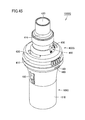
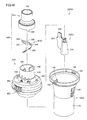
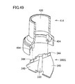
- FIG. 45 is a perspective view showing a nebulizer kit 1000G.
- FIG. 46 is a perspective view showing an exploded state of the nebulizer kit 1000G.
- the nebulizer kit 1000G includes a case body 100G, a suction channel forming body 200G (see FIG. 46), a particle sorting unit 300G (see FIG. 46), and a flow path forming body 400G.
- FIG. 47 is a cross-sectional perspective view showing the case body 100G and the suction path forming body 200G.
- the cylindrical portion 110 of the case body 100 ⁇ / b> G is provided with a concave portion 190 that is recessed from the inner side of the cylindrical portion 110 toward the outer side of the cylindrical portion 110.
- a configuration may be employed.
- the plate-like gripping portion 250 of the suction path forming body 200G is provided with a convex portion 290 that protrudes away from the cylindrical portion 210.
- the convex portion 290 of the suction path forming body 200G is fitted inside the concave portion 190 of the case body 100G (see FIG. 47).
- the suction path forming body 200G is fixed to the case body 100G.
- the wicking path forming body 200 see FIG. 3
- 200A see FIG. 15
- 200B see FIG. 16
- 200C in the above-described embodiments.
- FIG. 17 See FIG. 17), 200D (see FIG. 18), 200E (see FIG. 19), 200F (see FIG. 24), 200G (see FIG. 25) may be employed.
- the particle sorting unit 300G is provided with two blade portions 340 around the central shaft portion 330.
- the two blade portions 340 are independent from the cylindrical fixing portion 470 (corresponding to the upper cylindrical portion 320 in FIGS. 39 and 40).
- Each of the two blade portions 340 shields the space between the atomizing portion M and the aerosol discharge port 420 in a fan shape.
- a thin plate portion 344 extending upward is provided at the upper end of the blade portion 340.
- wing part 340 is adjusted by the blade
- the upper cylindrical portion 414 and the lower cylindrical portion 410 are fixed separately from each other.
- the lower cylindrical portion 410 is provided with a cylindrical fixing portion 470 extending upward.
- Two blade portions 440 are provided inside the cylindrical fixing portion 470 (see also FIG. 50).
- the shape of the blade portion 440 is formed in the same manner as the blade portion 340.
- the blade portion 440 is viewed from the cylindrical fixing portion 470 as the upper cylindrical portion 320 (see FIGS. 39 and 40) in the particle sorting portion 300G, the blade portion 440 is located inside the upper cylindrical portion 320 (particle sorting portion). (Close to the end).
- a scale 490 is provided outside the cylindrical fixing portion 470.
- FIG. 48 is a perspective view showing the upper cylindrical portion 414 of the flow path forming body 400G.
- a mounting recess 494 is provided inside the upper tubular portion 414.
- the mounting recess 494 corresponds to the shape of the thin plate portion 344 (see FIG. 46) of the particle sorting portion 300G (see FIG. 46).
- An instruction portion 492 corresponding to the scale 490 is suspended from the lower end of the upper cylindrical portion 414 (see also FIG. 46).
- FIG. 49 is a cross-sectional perspective view showing a state when the particle sorting part 300G and the upper cylindrical part 414 of the flow path forming body 400G are fixed to each other.
- the particle sorting section 300G is configured to be detachable from the flow path forming body 400G, and is sandwiched between the upper cylindrical section 414 and the lower cylindrical section 410 (see FIG. 46), whereby the flow path forming body. Fixed to 400G.
- the thin plate part 344 of the particle sorting part 300G is fitted inside the mounting recess 494 of the upper cylindrical part 414.
- the upper cylindrical portion 414 is rotated (see arrow AR492 in FIG. 51), the upper cylindrical portion 414 and the particle sorting unit 300G rotate integrally in the same direction.
- FIG. 50 is a cross-sectional perspective view showing a state when the particle sorting part 300G and the lower cylindrical part 410 of the flow path forming body 400G are fixed to each other.
- the particle sorting section 300G is fixed to the flow path forming body 400G by being sandwiched between the upper cylindrical section 414 (see FIG. 46) and the lower cylindrical section 410.
- the blade part 340 of the particle sorting part 300G is configured to be detachable from the lower cylindrical part 410 of the flow path forming body 400G.
- the particle sorting part 300G When the particle sorting part 300G is fixed to the flow path forming body 400G, the lower end of the central shaft part 330 of the particle sorting part 300G is fitted into a receiving part 450 provided at the center of the cylindrical fixing part 470.
- the upper cylindrical portion 414 see FIG. 49 and the like
- the particle sorting unit 300G rotates integrally with the upper cylindrical portion 414 around the receiving portion 450.
- FIG. 51 is a perspective view showing the operation of the nebulizer kit 1000G.
- the suction path forming body 200G (see FIG. 47) is fixed to the case body 100G (see FIG. 47).
- the aerosol generated in the atomizing section M (see FIG. 11, FIG. 32, etc.) moves toward the aerosol outlet 420 with a predetermined direction.
- the blade portion 340 (see FIG. 46 and the like) is located between the atomization portion M and the aerosol discharge port 420.
- wing part 340 is comprised so that adjustment is possible.
- FIG. 52 is a first plan view showing the particle sorting unit 300G and the flow path forming body 400G when looking down at the nebulizer kit 1000G from the aerosol discharge port 420.
- the indication part 492 of the upper cylindrical part 414 points to “MIN” on the scale 490 (see FIG. 51).
- FIG. 53 is a second plan view showing the particle sorting unit 300G and the flow path forming body 400G when the nebulizer kit 1000G is looked down from the aerosol discharge port 420.
- the indication part 492 of the upper cylindrical part 414 points to the part between “MIN” and “MAX” of the scale 490 (see FIG. 51).
- the blade portion 340 shown in FIG. 53 rotates in the clockwise direction by a predetermined angle with the rotation of the upper tubular portion 414, compared to the blade portion 340 shown in FIG.
- a part of the blade part 340 enters the lower part of the blade part 440.
- the aerosol passage formed between the atomizing section M and the aerosol discharge port 420 is slightly shielded by the blade section 340 and the blade section 440 (a part of the liquid storage section 116 is exposed).
- those having a large particle diameter may pass between the blades 340 and 440 and be discharged to the outside from the aerosol discharge port 420. it can.
- FIG. 54 is a third plan view showing the particle sorting unit 300G and the flow path forming body 400G when the nebulizer kit 1000G is looked down from the aerosol discharge port 420.
- the indication part 492 of the upper cylindrical part 414 points to “MAX” of the scale 490 (see FIG. 51).
- the blade portion 340 shown in FIG. 54 further rotates clockwise by a predetermined angle as the upper tubular portion 414 rotates, compared to the blade portion 340 shown in FIG.
- the posture of the blade portion 340 with respect to the atomizing portion M is adjusted.
- the rotation of the blade portion 340 increases or decreases the size of the aerosol passage formed between the atomizing portion M and the aerosol discharge port 420 (the shielding rate by the blade portion 340).
- the particle diameter of the aerosol discharged from the aerosol discharge port 420 depends on the size of the aerosol passage formed between the atomizing portion M and the aerosol discharge port 420. Therefore, according to the nebulizer kit 1000G, it is possible to obtain an aerosol having an optimum particle size according to a drug solution for treating diseases such as water, saline, bronchi, etc., or a vaccine administered to the user. .
- the inner diameter becomes smaller from the lower side (the portion near the atomizing portion M) toward the cylindrical fixing portion 470 (the aerosol discharge port 420). The diameter is reduced.
- the blade portion 440 and the blade portion 340 can effectively sort particles.
- the present embodiment will be described with reference to FIGS. 55 and 56.
- the nebulizer kit in the present embodiment includes a particle sorting unit 300H instead of the particle sorting unit 300G (see FIG. 46 and the like) in the above-described twenty-second embodiment, and instead of the flow path forming body 400G (see FIG. 46 and the like).
- a flow path forming body 400H is provided.
- the particle sorting unit 300H in the present embodiment has a plurality of blade portions 340A inside the cylindrical portion 322.
- the plurality of blade portions 340A are formed in a rod shape and are arranged in a substantially triangular shape in cross-sectional view.
- the plurality of blade portions 340A are in a positional relationship parallel to each other (see FIG. 56).
- Each of the plurality of blade portions 340A shields the space between the atomizing portion M and the aerosol discharge port 420 in a linear manner.
- a thin plate portion 344 that is fitted into the mounting concave portion 494 of the upper cylindrical portion 414 (see FIG. 46) is provided.
- a fitting convex portion 374 that is fitted into the fitting concave portion 474 of the cylindrical fixing portion 470 is provided.
- the aerosol generated in the atomizing section M moves toward the aerosol discharge port 420 (see FIG. 46) with a predetermined direction.
- the blade part 340A is located between the atomization part M and the aerosol discharge port 420.
- the posture of the blade portion 340A with respect to the atomizing portion M is configured to be adjustable.
- the posture of the blade portion 340A with respect to the atomizing portion M is adjusted.
- the rotation of the blade portion 340A increases or decreases the size of the aerosol passage formed between the atomizing portion M and the aerosol discharge port 420 (the shielding rate by the blade portion 340A).
- the particle diameter of the aerosol discharged from the aerosol discharge port 420 depends on the size of the aerosol passage formed between the atomizing portion M and the aerosol discharge port 420. Therefore, even with the nebulizer kit in the present embodiment, an aerosol having an optimal particle size can be obtained according to a drug solution for treating a disease such as water, saline, bronchi, etc., or a vaccine administered to a user. It becomes possible.
- the nebulizer kit in the present embodiment includes a particle sorting unit 300J instead of the particle sorting unit 300G (see FIG. 46 and the like) in the above-described twenty-second embodiment, and instead of the flow path forming body 400G (see FIG. 46 and the like).
- a flow path forming body 400J is provided.
- a connecting part 376, a gripping part 378, and a protruding part 388 are provided on the outer peripheral surface of the cylindrical part 322.
- the connection part 376 protrudes in the normal direction with respect to the cylindrical part 322.
- the grip portion 378 is provided so as to hang down from the distal end of the connecting portion 376 in the protruding direction.
- the shape of the connecting portion 376 corresponds to the shape of the uneven portion 476 of the flow path forming body 400J described below.
- the shape of the protrusion 388 corresponds to the shape of the groove 478 of the flow path forming body 400J described below.
- the protrusion 388 is fitted into the concave groove 478.
- the cylindrical fixing portion 470 is provided with an uneven portion 476.
- the concavo-convex portion 476 is provided along a direction parallel to the cylindrical axis direction of the cylindrical fixing portion 470.
- a connecting portion 376 of the particle sorting unit 300J is fitted into the uneven portion 476.
- the concavo-convex portion 476 can hold the particle sorting portion 300J at a predetermined height position by engaging with the connecting portion 376.
- a scale 496 is provided in the vicinity of the uneven portion 476 on the outer surface of the cylindrical fixing portion 470.
- the aerosol generated in the atomizing section M moves toward the aerosol discharge port 420 (see FIG. 57) with a predetermined direction.
- a blade portion 340 is located between the atomization portion M and the aerosol discharge port 420. The position of the blade part 340 with respect to the atomization part M is configured to be adjustable.
- the interval between the blade part 340 and the atomizing part M is increased or decreased by changing the position of the particle sorting part 300J with respect to the flow path forming body 400J using the gripping part 378.
- the particle diameter of the aerosol discharged from the aerosol discharge port 420 also depends on the distance between the blade portion 340 and the atomizing portion M. Therefore, even with the nebulizer kit in the present embodiment, an aerosol having an optimal particle size can be obtained according to a drug solution for treating a disease such as water, saline, bronchi, etc., or a vaccine administered to a user. It becomes possible.
- the nebulizer kit in the present embodiment includes a particle sorting unit 300K instead of the particle sorting unit 300G (see FIG. 46 and the like) in the above-described twenty-second embodiment, and instead of the flow path forming body 400G (see FIG. 46 and the like).
- a flow path forming body 400K is provided.
- a protruding portion 377 and a fitting convex portion 374 are provided on the outer peripheral surface of the cylindrical portion 322.
- the shape of the protruding portion 377 corresponds to the shape of the fitting long hole 427 of the flow path forming body 400K (upper cylindrical portion 414).
- the shape of the fitting convex portion 374 corresponds to the shape of the fitting concave portion 474 of the flow path forming body 400K (lower cylindrical portion 410).
- the fitting convex part 374 is fitted into the fitting concave part 474.
- a single blade portion 440 is provided inside the cylindrical portion 322, and the rod-shaped shaft portion 329 is supported by the blade portion 440.
- the rod-shaped shaft portion 329 is arranged along the tube axis of the tube-shaped portion 322.
- the particle sorting unit 300K has three blade portions 340B.
- a fitting hole 349 is provided in each of the three blade portions 340B.
- the three blade portions 340 ⁇ / b> B are sequentially fitted into the rod-shaped shaft portion 329 using the fitting hole portion 349.
- the fitting hole portion 349 may be configured to be frictionally engaged with the rod-shaped shaft portion 329.
- the aerosol generated in the atomizing section M moves toward the aerosol discharge port 420 (see FIG. 58) with a predetermined direction.
- wing part 340B is located between the atomization part M and the aerosol discharge port 420.
- wing part 340B is comprised so that adjustment is possible.
- the posture of the blade portion 340B with respect to the atomizing portion M is adjusted.
- the rotation of the blade portion 340B increases or decreases the size of the aerosol passage formed between the atomizing portion M and the aerosol discharge port 420 (the shielding rate by the blade portion 340B).
- the particle diameter of the aerosol discharged from the aerosol discharge port 420 depends on the size of the aerosol passage formed between the atomizing portion M and the aerosol discharge port 420. Therefore, even with the nebulizer kit in the present embodiment, an aerosol having an optimal particle size can be obtained according to a drug solution for treating a disease such as water, saline, bronchi, etc., or a vaccine administered to a user. It becomes possible.
- the three blade portions 340B can be attached at an independent angle with respect to the rod-shaped shaft portion 329. Since the shielding rate by the blade part 340B can be adjusted in a smaller range, the convenience in obtaining an aerosol having an optimum particle diameter is high. Moreover, since the blade
Abstract
Description
ケース体900は、有底筒状に形成される。ケース体900の上部には、上部開口902が設けられる。ケース体900の内部には、圧縮空気導入管913および液体貯留部916が設けられる。圧縮空気導入管913は、ケース体900の底面(液体貯留部916)側から上方側に向かって延在する。圧縮空気導入管913の内部には、圧縮空気(図示せず)が導入される。 (Case body 900)
The
霧化部形成体920は、吸液管形成部924、バッフル部922、およびバッフル支持部923を含む。吸液管形成部924は、筒状に形成される。吸液管形成部924の直径は、下方側から上方側に向かうにつれて小さくなる。吸液管形成部924の頂部には、開口部924aが設けられる。バッフル部922は、開口部924aの真上に位置する突起925を有する。突起925は必要に応じて設けられる。 (Atomization part forming body 920)
The atomization
流路形成体930は、ケース体900の上部開口902を塞ぐようにケース体900に取り付けられる。流路形成体930は、エアロゾル排出口932および外気導入管934を含む。エアロゾル排出口932は、流路形成体930の上部に設けられる。ケース体900の内部(霧化部M)で生成されたエアロゾルは、エアロゾル排出口932を通して外部に排出される。外気導入管934は、流路形成体930を上方から下方に向かって貫通するように設けられる。エアロゾルの生成に用いられる外気は、外気導入管934を通して、ケース体900の外部からケース体900の内部(霧化部M)に向かって導入される。 (Flow path forming body 930)
The flow
図61は、ネブライザキット1000Zにおける霧化部Mを拡大して示す断面図である。霧化部Mは、霧化部形成体920に設けられたバッフル部922(突起925)と、圧縮空気導入管913に設けられたノズル孔915(図60参照)との間に形成される。 (Atomization part M)
FIG. 61 is an enlarged cross-sectional view showing the atomizing portion M in the
好ましくは、上記ノズル孔は、円筒形状の内周面によって規定され、上記内周面は、外側に向かって拡径するテーパー面である。 Preferably, the liquid suction port has an opening shape extending in the lateral direction.
Preferably, the nozzle hole is defined by a cylindrical inner peripheral surface, and the inner peripheral surface is a tapered surface whose diameter increases toward the outside.
(ネブライザ2000)
図1を参照して、本実施の形態におけるネブライザ2000について説明する。ネブライザ2000は、本体510、チューブ512(圧縮空気管部)、ネブライザキット1000、およびマウスピース500を備える。本体510は、圧縮空気を送り出すコンプレッサー、および電子部品等を内蔵している。チューブ512は、可撓性を有する。チューブ512の一端は、本体510に設けられた圧縮空気送風口511に連結される。チューブ512の他端は、ネブライザキット1000に連結される。 [Embodiment 1]
(Nebulizer 2000)
A
図2は、ネブライザキット1000を示す斜視図である。図3は、ネブライザキット1000の分解した状態を示す斜視図である。図4は、ネブライザキット1000の分解した状態を示す断面図である。図5は、図2中におけるV-V線に沿った矢視断面図である。図2~図5を参照して、ネブライザキット1000は、ケース体100、吸上経路形成体200(図3~図5参照)、粒子選別部300(図3~図5参照)、および、流路形成体400を備える。 (Nebulizer kit 1000)
FIG. 2 is a perspective view showing the
図4を主として参照して、ケース体100は、筒状部110、開口部102(上方開口)、圧縮空気導入管113、および液体貯留部116を含み、全体として有底筒状に構成される。筒状部110は、下方側が液体貯留部116によって閉塞され、開口部102が設けられる上方側は開放される。筒状部110の開口部102の近傍には、嵌合孔部180が設けられる。流路形成体400がケース体100に取り付けられた状態においては、嵌合孔部180は、流路形成体400の嵌合凸部480と互いに嵌合する(図2,図3,図5参照)。 (Case body 100)
Referring mainly to FIG. 4, the
図6は、吸上経路形成体200を示す第1斜視図であり、斜め上方から見た吸上経路形成体200の全体構成を示している。図7は、図6におけるVII-VII線に沿った矢視断面斜視図であり、吸上経路形成体200を示す第1斜視断面図である。図7は、斜め上方から見た吸上経路形成体200の内部構造を示している。図8は、吸上経路形成体200を示す第2斜視図であり、斜め下方から見た吸上経路形成体200の全体構成を示している。図9は、図8におけるIX-IX線に沿った矢視断面斜視図であり、吸上経路形成体200を示す第2断面図である。図9は、斜め下方から見た吸上経路形成体200の内部構造を示している。 (Suction channel forming body 200)
FIG. 6 is a first perspective view showing the wicking
図12は、粒子選別部300を示す斜視図である。粒子選別部300は、全体としては、下方側から上方側に向かって縮径しつつ延在する略筒状に構成される。粒子選別部300は、下方筒状部310、上方筒状部320、中心軸部330、および4つの羽根部340を備える。下方筒状部310は、上方筒状部320と同軸状に配置される。下方筒状部310の直径は、上方筒状部320の直径よりも大きい。 (Particle sorting unit 300)
FIG. 12 is a perspective view showing the
図3~図5を再び参照して、流路形成体400は、ケース体100の開口部102を覆うようにケース体100に取り付けられる。流路形成体400は、下方筒状部410、中央筒状部412、上方筒状部414、エアロゾル排出口420、外気導入口430、および嵌合凸部480を備える。 (Flow path forming body 400)
3 to 5 again, the flow
図13および図14を参照して、ネブライザキット1000の動作について説明する。図13は、ネブライザキット1000(図2等参照)によってエアロゾルが形成される際の霧化部Mおよびその近傍を示す断面図である。図14は、ネブライザキット1000によってエアロゾルが形成される際のネブライザキット1000の全体の様子を示す断面図である。 (Operation of nebulizer kit 1000)
The operation of the
ネブライザキット1000においてエアロゾルが生成される際、ノズル孔115から噴き出された圧縮空気は、そのまま直線状に流れつつ(図13,図14における矢印AR113参照)、吸液口240から吐出された液体Wに接触する。ノズル孔115から噴き出された圧縮空気は、冒頭に説明したネブライザキット1000Z(図60~図62参照)とは異なり、他の部材に接触したり、大きく旋回したりすることなく、エアロゾルの生成に供される。圧縮空気導入管113に導入される圧縮空気としては、エアロゾルを生成する際に、圧力を損失することがほとんどない。 (Action / Effect)
When the aerosol is generated in the
図15を参照して、本実施の形態について説明する。本実施の形態におけるネブライザキットは、上述の実施の形態1における吸上経路形成体200(図13等参照)の代わりに、吸上経路形成体200Aを備える。 [Embodiment 2]
The present embodiment will be described with reference to FIG. The nebulizer kit in the present embodiment includes a wicking
図16を参照して、本実施の形態について説明する。本実施の形態におけるネブライザキットは、上述の実施の形態2における吸上経路形成体200A(図15等参照)の代わりに、吸上経路形成体200Bを備える。 [Embodiment 3]
This embodiment will be described with reference to FIG. The nebulizer kit in the present embodiment includes a wicking
図17を参照して、本実施の形態について説明する。本実施の形態におけるネブライザキットは、上述の実施の形態1における吸上経路形成体200(図10等参照)の代わりに、吸上経路形成体200Cを備える。 [Embodiment 4]
This embodiment will be described with reference to FIG. The nebulizer kit in the present embodiment includes a wicking
図18を参照して、本実施の形態について説明する。本実施の形態におけるネブライザキットは、上述の実施の形態1における吸上経路形成体200(図10等参照)の代わりに、吸上経路形成体200Dを備える。 [Embodiment 5]
The present embodiment will be described with reference to FIG. The nebulizer kit in the present embodiment includes a wicking
図19を参照して、本実施の形態について説明する。本実施の形態におけるネブライザキットは、上述の実施の形態1における吸上経路形成体200(図10等参照)の代わりに、吸上経路形成体200Eを備える。 [Embodiment 6]
The present embodiment will be described with reference to FIG. The nebulizer kit in the present embodiment includes a wicking
図20を参照して、本実施の形態について説明する。本実施の形態におけるネブライザキットは、上述の実施の形態3におけるケース体100(図16等参照)の代わりに、ケース体100Aを備える。以下に述べるケース体100Aの構成は、上述の実施の形態1(図10参照)、実施の形態2(図15参照)、実施の形態4(図17参照)、実施の形態5(図18参照)、および実施の形態6(図19参照)にも適用されることができる。 [Embodiment 7]
This embodiment will be described with reference to FIG. The nebulizer kit in the present embodiment includes a
図21を参照して、本実施の形態について説明する。本実施の形態におけるネブライザキットは、上述の実施の形態1におけるケース体100(図10等参照)の代わりに、ケース体100Bを備える。以下に述べるケース体100Bの構成は、上述の実施の形態2(図15参照)、実施の形態3(図16参照)、実施の形態4(図17参照)、実施の形態5(図18参照)、および実施の形態6(図19参照)にも適用されることができる。 [Embodiment 8]
This embodiment will be described with reference to FIG. The nebulizer kit in the present embodiment includes a
図22を参照して、本実施の形態について説明する。本実施の形態におけるネブライザキットは、上述の実施の形態1におけるケース体100(図10等参照)の代わりに、ケース体100Cを備える。以下に述べるケース体100Cの構成は、上述の実施の形態2(図15参照)、実施の形態3(図16参照)、実施の形態4(図17参照)、実施の形態5(図18参照)、および実施の形態6(図19参照)にも適用されることができる。 [Embodiment 9]
This embodiment will be described with reference to FIG. The nebulizer kit in the present embodiment includes a
図23および図24を参照して、本実施の形態について説明する。本実施の形態におけるネブライザキットは、上述の実施の形態1における吸上経路形成体200(図6,図7等参照)の代わりに、吸上経路形成体200Fを備える。以下に述べる吸上経路形成体200Fの構成は、上述の実施の形態2(図15参照)、実施の形態3(図16参照)、実施の形態4(図17参照)、実施の形態5(図18参照)、実施の形態6(図19参照)、実施の形態7(図20参照)、実施の形態8(図21参照)、および実施の形態9(図22参照)にも適用されることができる。 [Embodiment 10]
This embodiment will be described with reference to FIGS. 23 and 24. FIG. The nebulizer kit in the present embodiment includes a wicking
図25および図26を参照して、本実施の形態について説明する。本実施の形態におけるネブライザキットは、上述の実施の形態1における吸上経路形成体200(図6,図7等参照)の代わりに吸上経路形成体200Gを備え、上述の実施の形態1におけるケース体100(図10等参照)の代わりにケース体100Dを備える。 [Embodiment 11]
This embodiment will be described with reference to FIGS. 25 and 26. FIG. The nebulizer kit in the present embodiment includes a suction
図27~図29を参照して、本実施の形態について説明する。図27は、本実施の形態におけるネブライザキットの霧化部およびその近傍を示す斜視図である。図28は、図27におけるXXVIII-XXVIII線に沿った矢視断面図である。図29は、本実施の形態におけるネブライザキットの霧化部においてエアロゾルが生成される際の様子を模式的に示す断面図である。 [Embodiment 12]
This embodiment will be described with reference to FIGS. 27 to 29. FIG. FIG. 27 is a perspective view showing an atomizing portion of the nebulizer kit in the present embodiment and the vicinity thereof. 28 is a cross-sectional view taken along line XXVIII-XXVIII in FIG. FIG. 29 is a cross-sectional view schematically showing a state when aerosol is generated in the atomization portion of the nebulizer kit in the present embodiment.
図29を参照して、吸上経路形成体200Hによれば、吸液口240の上方に上部傾斜面領域270が設けられる。吸液口240および上部傾斜面領域270は、ノズル孔115から噴出された圧縮空気の進行経路(矢印AR113参照)に対して徐々に遠ざかるように傾斜している。吸液口240が傾斜して形成されるため(換言すると、吸液口240が上方に向かうにつれてノズル孔115から次第に離れるように形成されるため)、このような吸液口240の傾斜の程度を増減することによって、液体Wの供給量を調節することが可能となる。たとえば、吸液口240の傾斜の程度を大きくする(傾斜角度αの値を大きくする)ことによって、液体Wの供給量を減らして最適な値にすることができる。吸液口240の傾斜の程度を最適化することによって、ノズル孔115から噴き出される圧縮空気のエネルギーができるだけ多くの割合で液体Wの粉砕に使用されるようにすることができる。また、吸液口240が傾斜して形成されるため、ノズル孔115から噴出された圧縮空気が、吸液口240内に入り込むことも確実に抑制される。したがって、吸上経路形成体200Hによれば、液体Wを微粒化する上でのエネルギー使用効率をより一層向上させることが可能となる。 (Action / Effect)
Referring to FIG. 29, according to the suction
図30~図32を参照して、本実施の形態について説明する。図30は、本実施の形態におけるネブライザキットの霧化部およびその近傍を示す斜視図である。図31は、図30における矢印XXXI方向からみたケース体100などを示す平面図である。図32は、図30におけるXXXII-XXXII線に沿った矢視断面図である。 [Embodiment 13]
With reference to FIGS. 30 to 32, the present embodiment will be described. FIG. 30 is a perspective view showing an atomizing portion of the nebulizer kit in the present embodiment and the vicinity thereof. FIG. 31 is a plan view showing the
図33および図34を参照して、本実施の形態について説明する。図33は、本実施の形態におけるネブライザキットの霧化部およびその近傍を示す斜視図である。図34は、図33におけるXXXIV-XXXIV線に沿った矢視断面図である。 [Embodiment 14]
This embodiment will be described with reference to FIGS. 33 and 34. FIG. FIG. 33 is a perspective view showing an atomizing portion of the nebulizer kit in the present embodiment and the vicinity thereof. 34 is a cross-sectional view taken along the line XXXIV-XXXIV in FIG.
図35および図36を参照して、本実施の形態について説明する。図35は、本実施の形態におけるネブライザキットの霧化部およびその近傍を示す斜視図である。図36は、図35におけるXXXVI-XXXVI線に沿った矢視断面図である。 [Embodiment 15]
This embodiment will be described with reference to FIGS. 35 and 36. FIG. FIG. 35 is a perspective view showing an atomizing portion of the nebulizer kit and the vicinity thereof in the present embodiment. FIG. 36 is a cross-sectional view taken along line XXXVI-XXXVI in FIG.
図37および図38を参照して、本実施の形態について説明する。本実施の形態におけるネブライザキットは、上述の実施の形態1における粒子選別部300(図3等参照)の代わりに、粒子選別部300Aを備える。以下に述べる粒子選別部300Aの構成は、上述の実施の形態2~15にも適用されることができる。 [Embodiment 16]
This embodiment will be described with reference to FIGS. 37 and 38. FIG. The nebulizer kit in the present embodiment includes a
図39および図40を参照して、本実施の形態について説明する。本実施の形態におけるネブライザキットは、上述の実施の形態1における粒子選別部300(図3等参照)の代わりに粒子選別部300Bを備え、流路形成体400(図3等参照)の代わりに流路形成体400Bを備える。以下に述べる粒子選別部300Bおよび流路形成体400Bの構成は、上述の実施の形態2~15にも適用されることができる。 [Embodiment 17]
This embodiment will be described with reference to FIGS. 39 and 40. FIG. The nebulizer kit in the present embodiment includes a
図41を参照して、本実施の形態について説明する。本実施の形態におけるネブライザキットは、上述の実施の形態1における粒子選別部300(図3等参照)の代わりに粒子選別部300Cを備え、流路形成体400(図3等参照)の代わりに流路形成体400Cを備える。以下に述べる粒子選別部300Cおよび流路形成体400Cの構成は、上述の実施の形態2~15にも適用されることができる。 [Embodiment 18]
This embodiment will be described with reference to FIG. The nebulizer kit in the present embodiment includes a particle sorting unit 300C instead of the particle sorting unit 300 (see FIG. 3 and the like) in the first embodiment, and instead of the flow path forming body 400 (see FIG. 3 and the like). A flow
図42を参照して、本実施の形態について説明する。本実施の形態におけるネブライザキットは、上述の実施の形態1における粒子選別部300(図3等参照)の代わりに粒子選別部300Dを備え、流路形成体400(図3等参照)の代わりに流路形成体400Dを備える。以下に述べる粒子選別部300Dおよび流路形成体400Dの構成は、上述の実施の形態2~15にも適用されることができる。 [Embodiment 19]
This embodiment will be described with reference to FIG. The nebulizer kit in the present embodiment includes a
図43を参照して、本実施の形態について説明する。本実施の形態におけるネブライザキットは、上述の実施の形態1における粒子選別部300(図3等参照)の代わりに粒子選別部300Eを備え、流路形成体400(図3等参照)の代わりに流路形成体400Eを備える。以下に述べる粒子選別部300Eおよび流路形成体400Eの構成は、上述の実施の形態2~15にも適用されることができる。 [Embodiment 20]
This embodiment will be described with reference to FIG. The nebulizer kit in the present embodiment includes a
図44を参照して、本実施の形態について説明する。本実施の形態におけるネブライザキットは、上述の実施の形態1における粒子選別部300(図3等参照)の代わりに粒子選別部300Fを備え、流路形成体400(図3等参照)の代わりに流路形成体400Fを備える。以下に述べる粒子選別部300Fおよび流路形成体400Fの構成は、上述の実施の形態2~15にも適用されることができる。 [Embodiment 21]
The present embodiment will be described with reference to FIG. The nebulizer kit in the present embodiment includes a
図45~図54を参照して、本実施の形態におけるネブライザキット1000Gについて説明する。図45は、ネブライザキット1000Gを示す斜視図である。図46は、ネブライザキット1000Gの分解した状態を示す斜視図である。 [Embodiment 22]
With reference to FIGS. 45 to 54,
図45および図46に示すように、ネブライザキット1000Gは、ケース体100G、吸上経路形成体200G(図46参照)、粒子選別部300G(図46参照)、および流路形成体400Gを備える。 (
As shown in FIGS. 45 and 46, the
図47は、ケース体100Gおよび吸上経路形成体200Gを示す断面斜視図である。図46および図47に示すように、ケース体100Gの筒状部110には、筒状部110の内側から筒状部110の外側に向かって凹む凹部190が設けられる。ケース体100Gにおける凹部190以外の構成としては、上述の各実施の形態におけるケース体100A(図20参照),100B(図21参照),100C(図22参照),100D(図25参照)の各構成が採用されてもよい。 (
FIG. 47 is a cross-sectional perspective view showing the
図46を再び参照して、粒子選別部300Gは、中心軸部330の周りに、2枚の羽根部340が設けられる。粒子選別部300Gにおいては、筒状固定部470(図39,図40における上方筒状部320に相当)から2枚の羽根部340が独立した構成となっている。2枚の羽根部340の各々は、霧化部Mとエアロゾル排出口420との間の空間を扇状に遮蔽する。羽根部340の上端には、上方に向かって延在する薄板部344が設けられる。本実施の形態においては、羽根部340の霧化部M(図11,図32等参照)に対する姿勢が、羽根部340が回転することによって調節される。 (
Referring to FIG. 46 again, the
図51は、ネブライザキット1000Gの動作を示す斜視図である。ネブライザキット1000Gにおいては、吸上経路形成体200G(図47参照)がケース体100G(図47参照)に対して固定されている。霧化部M(図11,図32等参照)において生成されたエアロゾルは、所定の方向性を持ってエアロゾル排出口420に向かって移動する。ネブライザキット1000Gにおいては、霧化部Mとエアロゾル排出口420との間に、羽根部340(図46等参照)が位置する。羽根部340の霧化部Mに対する姿勢は、調節可能に構成される。 (Operation of
FIG. 51 is a perspective view showing the operation of the
羽根部340が回転することによって、羽根部340の霧化部Mに対する姿勢が調節される。羽根部340の回転によって、霧化部Mとエアロゾル排出口420との間に形成されるエアロゾルの通路の広さ(羽根部340による遮蔽率)が増減する。エアロゾル排出口420から排出されるエアロゾルの粒子径は、霧化部Mとエアロゾル排出口420との間に形成されるエアロゾルの通路の広さに依存する。したがって、ネブライザキット1000Gによれば、使用者に投与される水、食塩水、気管支等の疾患を治療する薬液、または、ワクチンに応じて、最適な粒子径を有するエアロゾルを得ることが可能となる。 (Action / Effect)
As the
図55および図56を参照して、本実施の形態について説明する。本実施の形態におけるネブライザキットは、上述の実施の形態22における粒子選別部300G(図46等参照)の代わりに粒子選別部300Hを備え、流路形成体400G(図46等参照)の代わりに流路形成体400Hを備える。 [Embodiment 23]
The present embodiment will be described with reference to FIGS. 55 and 56. The nebulizer kit in the present embodiment includes a
図57を参照して、本実施の形態について説明する。本実施の形態におけるネブライザキットは、上述の実施の形態22における粒子選別部300G(図46等参照)の代わりに粒子選別部300Jを備え、流路形成体400G(図46等参照)の代わりに流路形成体400Jを備える。 [Embodiment 24]
This embodiment will be described with reference to FIG. The nebulizer kit in the present embodiment includes a
図58および図59を参照して、本実施の形態について説明する。本実施の形態について説明する。本実施の形態におけるネブライザキットは、上述の実施の形態22における粒子選別部300G(図46等参照)の代わりに粒子選別部300Kを備え、流路形成体400G(図46等参照)の代わりに流路形成体400Kを備える。 [Embodiment 25]
This embodiment will be described with reference to FIGS. 58 and 59. This embodiment will be described. The nebulizer kit in the present embodiment includes a
Claims (7)
- 上方に向かって延在し、内部に圧縮空気が導入され、前記圧縮空気を噴出させるノズル孔(115)が上方先端部(113a)に形成された圧縮空気導入管(113)、および、前記圧縮空気導入管の下方側において前記圧縮空気導入管の外周面(113b)を取り囲むように設けられる液体貯留部(116)を含む、上方側が開放されたケース体(100)と、
前記圧縮空気導入管の前記外周面に覆い被せられることにより、前記液体貯留部に貯留された液体を前記圧縮空気導入管の前記上方先端部に向けて吸い上げる吸上経路(220)を形成するとともに、前記圧縮空気導入管に設けられた前記ノズル孔の出口領域(R115)に霧化部(M)を形成する吸上経路形成体(200)と、
前記霧化部で形成されたエアロゾルを外部に吐出するエアロゾル排出口(420)を含み、前記ケース体の上方開口(102)を覆うように前記ケース体に取り付けられる流路形成体(400)と、を備え、
前記吸上経路は、
前記圧縮空気導入管の前記外周面に沿って上方に向かって延在する第1吸上経路(221)と、
前記圧縮空気導入管の先端側において、前記第1吸上経路から前記ノズル孔側に向かって延在し、吸い上げられた前記液体を吐出する吸液口(240)を有する第2吸上経路(222)と、を含む、ネブライザキット。 A compressed air introduction pipe (113) that extends upward, into which compressed air is introduced, and has a nozzle hole (115) through which the compressed air is ejected is formed at the upper tip (113a); and the compression A case body (100) whose upper side is opened, including a liquid reservoir (116) provided so as to surround the outer peripheral surface (113b) of the compressed air introduction pipe on the lower side of the air introduction pipe;
By covering the outer peripheral surface of the compressed air introduction pipe, a suction path (220) for sucking the liquid stored in the liquid storage section toward the upper tip of the compressed air introduction pipe is formed. A suction path forming body (200) that forms an atomizing portion (M) in an outlet region (R115) of the nozzle hole provided in the compressed air introduction pipe,
A flow path forming body (400) that includes an aerosol discharge port (420) that discharges the aerosol formed in the atomizing portion to the outside and is attached to the case body so as to cover the upper opening (102) of the case body; With
The wicking path is
A first suction path (221) extending upward along the outer peripheral surface of the compressed air introduction pipe;
On the tip side of the compressed air introduction pipe, a second suction path (240) extending from the first suction path toward the nozzle hole side and having a liquid suction port (240) for discharging the sucked liquid. 222) and a nebulizer kit. - 前記吸液口から前記ノズル孔を見た場合に、前記ノズル孔の開口領域上に前記吸液口が位置している、
請求項1に記載のネブライザキット。 When viewing the nozzle hole from the liquid suction port, the liquid suction port is located on the opening region of the nozzle hole,
The nebulizer kit according to claim 1. - 前記ノズル孔は円形であり、
前記ノズル孔の中心線(115c)が、前記吸液口を含む面上に位置している、
請求項2に記載のネブライザキット。 The nozzle hole is circular;
The center line (115c) of the nozzle hole is located on the surface including the liquid suction port,
The nebulizer kit according to claim 2. - 前記第1吸上経路と前記第2吸上経路との交差領域には、前記第2吸上経路よりも流路断面積が大きい液溜まり部(260)が設けられている、
請求項1に記載のネブライザキット。 A liquid reservoir (260) having a larger cross-sectional area than the second wicking path is provided in an intersecting region between the first wicking path and the second wicking path.
The nebulizer kit according to claim 1. - 前記吸液口は、横方向に延在する開口形状である、
請求項1に記載のネブライザキット。 The liquid suction port has an opening shape extending in the lateral direction.
The nebulizer kit according to claim 1. - 前記ノズル孔は、円筒形状の内周面によって規定され、
前記内周面は、外側に向かって拡径するテーパー面である、
請求項1に記載のネブライザキット。 The nozzle hole is defined by a cylindrical inner peripheral surface,
The inner peripheral surface is a tapered surface that expands toward the outside.
The nebulizer kit according to claim 1. - 圧縮空気を送り出すコンプレッサーを有する本体(510)と、
前記コンプレッサーから送り出される圧縮空気が導入される圧縮空気管部(512)と、
前記圧縮空気管部の一端が連結され、エアロゾルを生成する請求項1に記載のネブライザキットと、を備える、
ネブライザ。 A body (510) having a compressor for delivering compressed air;
A compressed air pipe section (512) into which compressed air sent out from the compressor is introduced;
The nebulizer kit according to claim 1, wherein one end of the compressed air pipe part is connected to generate an aerosol.
Nebulizer.
Priority Applications (3)
| Application Number | Priority Date | Filing Date | Title |
|---|---|---|---|
| DE112012005482.2T DE112012005482T5 (en) | 2011-12-27 | 2012-10-09 | Nebulizer and nebulizer kit |
| CN201280065021.0A CN104023773B (en) | 2011-12-27 | 2012-10-09 | Sprayer and sprayer external member |
| US14/288,941 US9522242B2 (en) | 2011-12-27 | 2014-05-28 | Nebulizer and nebulizer kit |
Applications Claiming Priority (2)
| Application Number | Priority Date | Filing Date | Title |
|---|---|---|---|
| JP2011-285861 | 2011-12-27 | ||
| JP2011285861A JP5929176B2 (en) | 2011-12-27 | 2011-12-27 | Nebulizer and nebulizer kit |
Related Child Applications (1)
| Application Number | Title | Priority Date | Filing Date |
|---|---|---|---|
| US14/288,941 Continuation US9522242B2 (en) | 2011-12-27 | 2014-05-28 | Nebulizer and nebulizer kit |
Publications (1)
| Publication Number | Publication Date |
|---|---|
| WO2013099397A1 true WO2013099397A1 (en) | 2013-07-04 |
Family
ID=48696902
Family Applications (1)
| Application Number | Title | Priority Date | Filing Date |
|---|---|---|---|
| PCT/JP2012/076115 WO2013099397A1 (en) | 2011-12-27 | 2012-10-09 | Nebulizer and nebulizer kit |
Country Status (5)
| Country | Link |
|---|---|
| US (1) | US9522242B2 (en) |
| JP (1) | JP5929176B2 (en) |
| CN (1) | CN104023773B (en) |
| DE (1) | DE112012005482T5 (en) |
| WO (1) | WO2013099397A1 (en) |
Cited By (7)
| Publication number | Priority date | Publication date | Assignee | Title |
|---|---|---|---|---|
| CN106029139A (en) * | 2014-02-27 | 2016-10-12 | 欧姆龙健康医疗事业株式会社 | Nebulizer and nebulizer kit |
| US9539408B2 (en) | 2012-10-31 | 2017-01-10 | Trudell Medical International | Nebulizer apparatus |
| US10786638B2 (en) | 2016-07-08 | 2020-09-29 | Trudell Medical International | Nebulizer apparatus and method |
| US11497867B2 (en) | 2016-12-09 | 2022-11-15 | Trudell Medical International | Smart nebulizer |
| US11666801B2 (en) | 2018-01-04 | 2023-06-06 | Trudell Medical International | Smart oscillating positive expiratory pressure device |
| US11712175B2 (en) | 2019-08-27 | 2023-08-01 | Trudell Medical International | Smart oscillating positive expiratory pressure device with feedback indicia |
| US11839716B2 (en) | 2016-07-08 | 2023-12-12 | Trudell Medical International | Smart oscillating positive expiratory pressure device |
Families Citing this family (17)
| Publication number | Priority date | Publication date | Assignee | Title |
|---|---|---|---|---|
| JP1515878S (en) * | 2014-03-12 | 2015-01-26 | ||
| USD796664S1 (en) * | 2014-05-13 | 2017-09-05 | Khalil A Hill | Visual flow indicator rotating nebulizer |
| USD806857S1 (en) * | 2014-06-19 | 2018-01-02 | Shenzhen Lfs Medical Device Co., Ltd. | Super-micro nebulizer |
| TWD168862S (en) * | 2014-11-21 | 2015-07-01 | 台達電子工業股份有限公司 | Spray can part |
| TWD169846S (en) * | 2014-12-12 | 2015-08-11 | 李文欽 | Sprayer(2) |
| KR101870431B1 (en) * | 2016-11-01 | 2018-06-22 | 주식회사 위그린 | apparatus for vapouring chemical treatment liquid to disinfecting air |
| KR101929013B1 (en) * | 2017-03-15 | 2018-12-13 | 주식회사 에스엠뿌레 | Device typed desktop for spraying chemical liquid |
| DE102017119462A1 (en) * | 2017-08-25 | 2019-02-28 | Gelupas Gmbh | Dispensing device for spraying a sprayable fluid or powder |
| CN109718433B (en) * | 2017-10-31 | 2024-02-20 | 正大天晴药业集团股份有限公司 | Inhalation atomizer kit |
| CN208711985U (en) * | 2017-11-26 | 2019-04-09 | 广州丹绮环保科技有限公司 | A kind of humidifier |
| CN110652648B (en) * | 2018-08-01 | 2021-05-28 | 浙江探针生物科技有限公司 | Device for delivering medicament, and apparatus and assembly thereof |
| CN108704202B (en) * | 2018-08-15 | 2024-04-05 | 威海盛洁医疗科技有限公司 | Medical administration atomizing cup |
| JP7182104B2 (en) * | 2019-03-28 | 2022-12-02 | パナソニックIpマネジメント株式会社 | spraying device |
| US11815704B2 (en) * | 2019-03-29 | 2023-11-14 | Panasonic Intellectual Property Corporation Of America | Light beam emission system |
| JP7409557B2 (en) | 2021-03-26 | 2024-01-09 | 株式会社村田製作所 | atomizer |
| DE112022000633T5 (en) | 2021-03-26 | 2023-11-02 | Murata Manufacturing Co., Ltd. | ATOMIZER |
| CN116439872B (en) * | 2023-06-16 | 2023-08-22 | 内蒙古美羊牧业科技有限公司 | Vaccine atomizing device |
Citations (5)
| Publication number | Priority date | Publication date | Assignee | Title |
|---|---|---|---|---|
| JPS5652070A (en) * | 1979-07-25 | 1981-05-09 | Bard Inc C R | Nebulizer device |
| JPS581463A (en) * | 1981-06-26 | 1983-01-06 | テルモ株式会社 | Neburizer with heater |
| JPS602545U (en) * | 1983-06-17 | 1985-01-10 | ノトヤ医科器械株式会社 | nebulizer |
| JP2000217916A (en) * | 1999-01-01 | 2000-08-08 | Masakazu Imai | Particle selective nebulizer which is operated by both man power and electrical power and its manufacture |
| JP2007508078A (en) * | 2003-10-16 | 2007-04-05 | パリ ゲーエムベーハー シュペツィアリステン フューア エフェクティブ インハレツィオーン | Inhalation therapy device with nozzle nebulizer |
Family Cites Families (5)
| Publication number | Priority date | Publication date | Assignee | Title |
|---|---|---|---|---|
| US3762409A (en) * | 1970-11-03 | 1973-10-02 | V Lester | Nebulizer |
| ES2029248T3 (en) * | 1986-09-22 | 1992-08-01 | Omron Tateisi Electronics Co. | SPRAYER. |
| DK0540774T3 (en) | 1991-11-07 | 1995-07-10 | Ritzau Pari Werk Gmbh Paul | liquid sprayer |
| GB9422821D0 (en) * | 1994-11-11 | 1995-01-04 | Aid Medic Ltd | Atomizer |
| US5584285A (en) * | 1995-06-07 | 1996-12-17 | Salter Labs | Breathing circuit apparatus for a nebulizer |
-
2011
- 2011-12-27 JP JP2011285861A patent/JP5929176B2/en active Active
-
2012
- 2012-10-09 DE DE112012005482.2T patent/DE112012005482T5/en active Pending
- 2012-10-09 CN CN201280065021.0A patent/CN104023773B/en active Active
- 2012-10-09 WO PCT/JP2012/076115 patent/WO2013099397A1/en active Application Filing
-
2014
- 2014-05-28 US US14/288,941 patent/US9522242B2/en active Active
Patent Citations (5)
| Publication number | Priority date | Publication date | Assignee | Title |
|---|---|---|---|---|
| JPS5652070A (en) * | 1979-07-25 | 1981-05-09 | Bard Inc C R | Nebulizer device |
| JPS581463A (en) * | 1981-06-26 | 1983-01-06 | テルモ株式会社 | Neburizer with heater |
| JPS602545U (en) * | 1983-06-17 | 1985-01-10 | ノトヤ医科器械株式会社 | nebulizer |
| JP2000217916A (en) * | 1999-01-01 | 2000-08-08 | Masakazu Imai | Particle selective nebulizer which is operated by both man power and electrical power and its manufacture |
| JP2007508078A (en) * | 2003-10-16 | 2007-04-05 | パリ ゲーエムベーハー シュペツィアリステン フューア エフェクティブ インハレツィオーン | Inhalation therapy device with nozzle nebulizer |
Cited By (8)
| Publication number | Priority date | Publication date | Assignee | Title |
|---|---|---|---|---|
| US9539408B2 (en) | 2012-10-31 | 2017-01-10 | Trudell Medical International | Nebulizer apparatus |
| US10668229B2 (en) | 2012-10-31 | 2020-06-02 | Trude Medical International | Nebulizer apparatus |
| CN106029139A (en) * | 2014-02-27 | 2016-10-12 | 欧姆龙健康医疗事业株式会社 | Nebulizer and nebulizer kit |
| US10786638B2 (en) | 2016-07-08 | 2020-09-29 | Trudell Medical International | Nebulizer apparatus and method |
| US11839716B2 (en) | 2016-07-08 | 2023-12-12 | Trudell Medical International | Smart oscillating positive expiratory pressure device |
| US11497867B2 (en) | 2016-12-09 | 2022-11-15 | Trudell Medical International | Smart nebulizer |
| US11666801B2 (en) | 2018-01-04 | 2023-06-06 | Trudell Medical International | Smart oscillating positive expiratory pressure device |
| US11712175B2 (en) | 2019-08-27 | 2023-08-01 | Trudell Medical International | Smart oscillating positive expiratory pressure device with feedback indicia |
Also Published As
| Publication number | Publication date |
|---|---|
| US9522242B2 (en) | 2016-12-20 |
| US20140263740A1 (en) | 2014-09-18 |
| JP5929176B2 (en) | 2016-06-01 |
| JP2013132471A (en) | 2013-07-08 |
| CN104023773A (en) | 2014-09-03 |
| CN104023773B (en) | 2016-05-18 |
| DE112012005482T5 (en) | 2014-09-11 |
Similar Documents
| Publication | Publication Date | Title |
|---|---|---|
| JP5929176B2 (en) | Nebulizer and nebulizer kit | |
| WO2013099399A1 (en) | Nebulizer and nebulizer kit | |
| JP6035738B2 (en) | Nebulizer and nebulizer kit | |
| JP6174056B2 (en) | Inhalation device and mixing channel for inhalation device | |
| CN103041480B (en) | Atomization device and nozzle thereof | |
| JP5517139B1 (en) | Nebulizer | |
| WO2011114813A1 (en) | Nebulizer kit and nebulizer | |
| CN109718431B (en) | Medical vaporizer with improved internal air flow | |
| JP3218212U (en) | Chemical atomizer | |
| US20140060526A1 (en) | Medical atomizer | |
| JPH05277188A (en) | Drug sprayer with improved aerosol room | |
| CN103405835A (en) | Integrated medical vaporizer | |
| CN105833398B (en) | High-efficient atomizing cup with guiding device | |
| JP2010519963A (en) | Nozzle type spraying system | |
| JP2007195838A (en) | Nebulizer | |
| CN209316733U (en) | Vaporizer | |
| JPH04244168A (en) | Spray for drug | |
| CN110251782A (en) | A kind of medical atomization device | |
| CN108704202B (en) | Medical administration atomizing cup | |
| CN208959018U (en) | A kind of medical administration atomizing cup | |
| CA3067131A1 (en) | Multiliquid-nozzle | |
| CN208362004U (en) | It is a kind of for stain disease administer plugflow aeration machine on atomizer | |
| NL2023033B1 (en) | Spray inhaler device | |
| TWI500432B (en) | Nebulizer and nozzle thereof | |
| TWM451977U (en) | Medicine spray bottle |
Legal Events
| Date | Code | Title | Description |
|---|---|---|---|
| DPE2 | Request for preliminary examination filed before expiration of 19th month from priority date (pct application filed from 20040101) | ||
| 121 | Ep: the epo has been informed by wipo that ep was designated in this application |
Ref document number: 12861772 Country of ref document: EP Kind code of ref document: A1 |
|
| WWE | Wipo information: entry into national phase |
Ref document number: 1120120054822 Country of ref document: DE Ref document number: 112012005482 Country of ref document: DE |
|
| 122 | Ep: pct application non-entry in european phase |
Ref document number: 12861772 Country of ref document: EP Kind code of ref document: A1 |
|
| 122 | Ep: pct application non-entry in european phase |
Ref document number: 12861772 Country of ref document: EP Kind code of ref document: A1 |