WO2013094362A1 - Measurement device, measurement method, program, and recording medium - Google Patents
Measurement device, measurement method, program, and recording medium Download PDFInfo
- Publication number
- WO2013094362A1 WO2013094362A1 PCT/JP2012/080334 JP2012080334W WO2013094362A1 WO 2013094362 A1 WO2013094362 A1 WO 2013094362A1 JP 2012080334 W JP2012080334 W JP 2012080334W WO 2013094362 A1 WO2013094362 A1 WO 2013094362A1
- Authority
- WO
- WIPO (PCT)
- Prior art keywords
- measurement
- living body
- unit
- measurement light
- light
- Prior art date
Links
- 238000005259 measurement Methods 0.000 title claims abstract description 441
- 238000000691 measurement method Methods 0.000 title claims abstract description 10
- 230000010287 polarization Effects 0.000 claims abstract description 228
- 238000001514 detection method Methods 0.000 claims abstract description 108
- 230000003287 optical effect Effects 0.000 claims abstract description 92
- 238000004458 analytical method Methods 0.000 claims abstract description 73
- 230000008859 change Effects 0.000 claims abstract description 39
- 238000000034 method Methods 0.000 claims description 19
- 239000008280 blood Substances 0.000 claims description 16
- 210000004369 blood Anatomy 0.000 claims description 16
- WQZGKKKJIJFFOK-GASJEMHNSA-N Glucose Natural products OC[C@H]1OC(O)[C@H](O)[C@@H](O)[C@@H]1O WQZGKKKJIJFFOK-GASJEMHNSA-N 0.000 claims description 13
- 239000008103 glucose Substances 0.000 claims description 13
- 230000010349 pulsation Effects 0.000 claims description 10
- 238000001228 spectrum Methods 0.000 claims description 8
- 210000001367 artery Anatomy 0.000 claims description 6
- 230000002123 temporal effect Effects 0.000 claims description 6
- 238000000862 absorption spectrum Methods 0.000 claims description 5
- 239000000306 component Substances 0.000 description 73
- 230000006870 function Effects 0.000 description 19
- 239000000126 substance Substances 0.000 description 18
- 238000004891 communication Methods 0.000 description 17
- 238000010586 diagram Methods 0.000 description 11
- 238000012545 processing Methods 0.000 description 11
- 230000005540 biological transmission Effects 0.000 description 10
- HVYWMOMLDIMFJA-DPAQBDIFSA-N cholesterol Chemical compound C1C=C2C[C@@H](O)CC[C@]2(C)[C@@H]2[C@@H]1[C@@H]1CC[C@H]([C@H](C)CCCC(C)C)[C@@]1(C)CC2 HVYWMOMLDIMFJA-DPAQBDIFSA-N 0.000 description 6
- 239000012503 blood component Substances 0.000 description 5
- 238000004364 calculation method Methods 0.000 description 5
- 239000004065 semiconductor Substances 0.000 description 5
- 239000013598 vector Substances 0.000 description 5
- 230000008569 process Effects 0.000 description 4
- 102000009027 Albumins Human genes 0.000 description 3
- 108010088751 Albumins Proteins 0.000 description 3
- 235000012000 cholesterol Nutrition 0.000 description 3
- 238000004590 computer program Methods 0.000 description 3
- 239000000463 material Substances 0.000 description 3
- 238000000491 multivariate analysis Methods 0.000 description 3
- 238000000926 separation method Methods 0.000 description 3
- 102000001554 Hemoglobins Human genes 0.000 description 2
- 108010054147 Hemoglobins Proteins 0.000 description 2
- XUMBMVFBXHLACL-UHFFFAOYSA-N Melanin Chemical compound O=C1C(=O)C(C2=CNC3=C(C(C(=O)C4=C32)=O)C)=C2C4=CNC2=C1C XUMBMVFBXHLACL-UHFFFAOYSA-N 0.000 description 2
- 230000000295 complement effect Effects 0.000 description 2
- 238000009434 installation Methods 0.000 description 2
- 230000031700 light absorption Effects 0.000 description 2
- 229910044991 metal oxide Inorganic materials 0.000 description 2
- 150000004706 metal oxides Chemical class 0.000 description 2
- 238000005070 sampling Methods 0.000 description 2
- 239000013076 target substance Substances 0.000 description 2
- OKTJSMMVPCPJKN-UHFFFAOYSA-N Carbon Chemical compound [C] OKTJSMMVPCPJKN-UHFFFAOYSA-N 0.000 description 1
- 229910000530 Gallium indium arsenide Inorganic materials 0.000 description 1
- 235000019687 Lamb Nutrition 0.000 description 1
- 238000003491 array Methods 0.000 description 1
- QVGXLLKOCUKJST-UHFFFAOYSA-N atomic oxygen Chemical compound [O] QVGXLLKOCUKJST-UHFFFAOYSA-N 0.000 description 1
- 239000012620 biological material Substances 0.000 description 1
- 230000015572 biosynthetic process Effects 0.000 description 1
- 229910052799 carbon Inorganic materials 0.000 description 1
- 239000013078 crystal Substances 0.000 description 1
- 238000007405 data analysis Methods 0.000 description 1
- 238000013500 data storage Methods 0.000 description 1
- 238000003384 imaging method Methods 0.000 description 1
- 230000003993 interaction Effects 0.000 description 1
- 239000004973 liquid crystal related substance Substances 0.000 description 1
- 239000000203 mixture Substances 0.000 description 1
- 238000012986 modification Methods 0.000 description 1
- 230000004048 modification Effects 0.000 description 1
- 229910052760 oxygen Inorganic materials 0.000 description 1
- 239000001301 oxygen Substances 0.000 description 1
- 206010033675 panniculitis Diseases 0.000 description 1
- 230000002093 peripheral effect Effects 0.000 description 1
- 239000000049 pigment Substances 0.000 description 1
- 238000011160 research Methods 0.000 description 1
- 239000007787 solid Substances 0.000 description 1
- 230000005236 sound signal Effects 0.000 description 1
- 210000004304 subcutaneous tissue Anatomy 0.000 description 1
- 239000000758 substrate Substances 0.000 description 1
- 230000001360 synchronised effect Effects 0.000 description 1
- 238000003786 synthesis reaction Methods 0.000 description 1
- 239000010409 thin film Substances 0.000 description 1
Images

Classifications
-
- A—HUMAN NECESSITIES
- A61—MEDICAL OR VETERINARY SCIENCE; HYGIENE
- A61B—DIAGNOSIS; SURGERY; IDENTIFICATION
- A61B5/00—Measuring for diagnostic purposes; Identification of persons
- A61B5/145—Measuring characteristics of blood in vivo, e.g. gas concentration, pH value; Measuring characteristics of body fluids or tissues, e.g. interstitial fluid, cerebral tissue
- A61B5/1455—Measuring characteristics of blood in vivo, e.g. gas concentration, pH value; Measuring characteristics of body fluids or tissues, e.g. interstitial fluid, cerebral tissue using optical sensors, e.g. spectral photometrical oximeters
-
- A—HUMAN NECESSITIES
- A61—MEDICAL OR VETERINARY SCIENCE; HYGIENE
- A61B—DIAGNOSIS; SURGERY; IDENTIFICATION
- A61B5/00—Measuring for diagnostic purposes; Identification of persons
- A61B5/0059—Measuring for diagnostic purposes; Identification of persons using light, e.g. diagnosis by transillumination, diascopy, fluorescence
- A61B5/0082—Measuring for diagnostic purposes; Identification of persons using light, e.g. diagnosis by transillumination, diascopy, fluorescence adapted for particular medical purposes
- A61B5/0084—Measuring for diagnostic purposes; Identification of persons using light, e.g. diagnosis by transillumination, diascopy, fluorescence adapted for particular medical purposes for introduction into the body, e.g. by catheters
-
- A—HUMAN NECESSITIES
- A61—MEDICAL OR VETERINARY SCIENCE; HYGIENE
- A61B—DIAGNOSIS; SURGERY; IDENTIFICATION
- A61B5/00—Measuring for diagnostic purposes; Identification of persons
- A61B5/02—Detecting, measuring or recording pulse, heart rate, blood pressure or blood flow; Combined pulse/heart-rate/blood pressure determination; Evaluating a cardiovascular condition not otherwise provided for, e.g. using combinations of techniques provided for in this group with electrocardiography or electroauscultation; Heart catheters for measuring blood pressure
- A61B5/024—Detecting, measuring or recording pulse rate or heart rate
- A61B5/02416—Detecting, measuring or recording pulse rate or heart rate using photoplethysmograph signals, e.g. generated by infrared radiation
- A61B5/02427—Details of sensor
-
- A—HUMAN NECESSITIES
- A61—MEDICAL OR VETERINARY SCIENCE; HYGIENE
- A61B—DIAGNOSIS; SURGERY; IDENTIFICATION
- A61B5/00—Measuring for diagnostic purposes; Identification of persons
- A61B5/145—Measuring characteristics of blood in vivo, e.g. gas concentration, pH value; Measuring characteristics of body fluids or tissues, e.g. interstitial fluid, cerebral tissue
- A61B5/14532—Measuring characteristics of blood in vivo, e.g. gas concentration, pH value; Measuring characteristics of body fluids or tissues, e.g. interstitial fluid, cerebral tissue for measuring glucose, e.g. by tissue impedance measurement
-
- A—HUMAN NECESSITIES
- A61—MEDICAL OR VETERINARY SCIENCE; HYGIENE
- A61B—DIAGNOSIS; SURGERY; IDENTIFICATION
- A61B5/00—Measuring for diagnostic purposes; Identification of persons
- A61B5/145—Measuring characteristics of blood in vivo, e.g. gas concentration, pH value; Measuring characteristics of body fluids or tissues, e.g. interstitial fluid, cerebral tissue
- A61B5/1455—Measuring characteristics of blood in vivo, e.g. gas concentration, pH value; Measuring characteristics of body fluids or tissues, e.g. interstitial fluid, cerebral tissue using optical sensors, e.g. spectral photometrical oximeters
- A61B5/14551—Measuring characteristics of blood in vivo, e.g. gas concentration, pH value; Measuring characteristics of body fluids or tissues, e.g. interstitial fluid, cerebral tissue using optical sensors, e.g. spectral photometrical oximeters for measuring blood gases
- A61B5/14552—Details of sensors specially adapted therefor
-
- A—HUMAN NECESSITIES
- A61—MEDICAL OR VETERINARY SCIENCE; HYGIENE
- A61B—DIAGNOSIS; SURGERY; IDENTIFICATION
- A61B5/00—Measuring for diagnostic purposes; Identification of persons
- A61B5/145—Measuring characteristics of blood in vivo, e.g. gas concentration, pH value; Measuring characteristics of body fluids or tissues, e.g. interstitial fluid, cerebral tissue
- A61B5/1455—Measuring characteristics of blood in vivo, e.g. gas concentration, pH value; Measuring characteristics of body fluids or tissues, e.g. interstitial fluid, cerebral tissue using optical sensors, e.g. spectral photometrical oximeters
- A61B5/14558—Measuring characteristics of blood in vivo, e.g. gas concentration, pH value; Measuring characteristics of body fluids or tissues, e.g. interstitial fluid, cerebral tissue using optical sensors, e.g. spectral photometrical oximeters by polarisation
-
- A—HUMAN NECESSITIES
- A61—MEDICAL OR VETERINARY SCIENCE; HYGIENE
- A61B—DIAGNOSIS; SURGERY; IDENTIFICATION
- A61B2560/00—Constructional details of operational features of apparatus; Accessories for medical measuring apparatus
- A61B2560/02—Operational features
- A61B2560/0223—Operational features of calibration, e.g. protocols for calibrating sensors
-
- A—HUMAN NECESSITIES
- A61—MEDICAL OR VETERINARY SCIENCE; HYGIENE
- A61B—DIAGNOSIS; SURGERY; IDENTIFICATION
- A61B5/00—Measuring for diagnostic purposes; Identification of persons
- A61B5/01—Measuring temperature of body parts ; Diagnostic temperature sensing, e.g. for malignant or inflamed tissue
Definitions
- the present disclosure relates to a measuring device, a measuring method, a program, and a recording medium.
- the concentration of the biological component is measured based on the intensity of light (transmitted light) that has passed through the living body. It is an object that scatters well, and part of the irradiated light is absorbed by each biological component contained in the living body, so there is a possibility that sufficient transmitted light cannot be obtained depending on the intensity of the irradiated light is there. Therefore, in the biological component concentration measuring apparatus using the non-invasive optical method as shown in Patent Document 1, a light source capable of emitting light with sufficient intensity and a detector capable of detecting weak transmitted light are used. The device tends to be large. Further, when measuring blood glucose concentration as a biological component, it is necessary to measure changes due to scatter of transmitted light and pulsation of transmitted light, which makes the apparatus large. Therefore, it is required to reduce the size of the apparatus while maintaining the detection accuracy.
- the present disclosure proposes a measuring device, a measuring method, a program, and a recording medium that can further reduce the size of the device.
- a light source unit that emits measurement light having at least one wavelength for measuring a biological component contained in a living body, and a detection unit that detects the measurement light emitted from the inside of the living body
- a measurement unit having a polarization control unit that is provided between at least one of the light source unit and the living body or between the living body and the detection unit and controls the polarization direction of the measurement light.
- An analysis unit that calculates an optical rotation based on a change in a polarization state of the measurement light using a measurement result by the measurement unit, and analyzes a concentration of the biological component based on the calculated optical rotation A measuring device is provided.
- the present disclosure emitting measurement light having at least one wavelength for measuring a biological component contained in a living body, between the light source of the measuring light and the living body, or Controlling the polarization direction of the measurement light at at least one of the position between the living body and the detection unit for detecting the measurement light emitted from the inside of the living body; Detecting the measurement light, and calculating the optical rotation based on a change in the polarization state of the measurement light using the detection result of the measurement light, and the concentration of the biological component based on the calculated optical rotation And a measurement method is provided.
- a light source unit that emits measurement light having at least one wavelength for measuring a biological component contained in the living body, and the measurement light emitted from the living body is detected.
- Measurement having a detection unit and a polarization control unit that is provided between at least one of the light source unit and the living body or between the living body and the detection unit and controls the polarization direction of the measurement light.
- a program for realizing the analysis function is provided.
- a light source unit that emits measurement light having at least one wavelength for measuring a biological component contained in the living body, and the measurement light emitted from the living body is detected.
- Measurement having a detection unit and a polarization control unit that is provided between at least one of the light source unit and the living body or between the living body and the detection unit and controls the polarization direction of the measurement light.
- a recording medium on which a program for realizing the analysis function is recorded is provided.
- a light source unit that emits measurement light having at least one wavelength for measuring a biological component contained in the living body, and the measurement light emitted from the living body is detected.
- Measurement having a detection unit and a polarization control unit that is provided between at least one of the light source unit and the living body or between the living body and the detection unit and controls the polarization direction of the measurement light.
- an analysis unit that calculates the optical rotation based on a change in the polarization state of the measurement light using a measurement result by the measurement unit, and analyzes the concentration of the biological component based on the calculated optical rotation
- a measurement control unit that controls the measurement unit, and the measurement unit detects the measurement light emitted from the living body as a result of the measurement light scattered inside the living body being reflected inside the living body.
- Measurement unit The measurement control unit, to switch in a time division polarization direction of the measurement light measuring device is provided.
- a light source unit that emits measurement light having at least one wavelength for measuring a biological component contained in the living body, and the measurement light emitted from the living body is detected.
- a detection unit, and a polarization control unit that is provided between at least one of the light source unit and the living body, or between the living body and the detection unit, and controls the polarization direction of the measurement light.
- the measurement light scattered inside the living body is reflected inside the living body, and as a result, the computer can communicate with the measuring equipment that detects the measurement light emitted from the living body.
- An optical rotation is calculated based on a change in the polarization state of the measurement light, and an analysis function for analyzing the concentration of the biological component based on the calculated optical rotation and a control function for the measurement instrument are realized.
- Professional Lamb is provided.
- the polarization direction of the measurement light is controlled by the polarization control unit until the measurement light emitted from the light source unit is emitted from the living body and detected by the detection unit.
- the analysis unit calculates the optical rotation based on the change in the polarization state of the measurement light using the measurement result measured by the measurement unit, and analyzes the concentration of the biological component based on the calculated optical rotation.
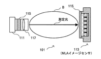
- FIG. 1 is an explanatory diagram for explaining the principle of concentration measurement based on optical rotation.
- an electromagnetic wave including light can be considered as a transverse wave oscillating in various directions perpendicular to the traveling direction (for example, a vertical direction, a horizontal direction, an oblique direction, etc.).
- a specific direction there may be light oscillating in a specific direction.
- Such light oscillating in a specific direction is called polarized light.
- polarized light there is circular polarized light whose vibration direction forms a circle as light propagates, planar polarized light (also referred to as plane polarized light) that vibrates only in a specific direction, and the like.
- the circularly polarized light includes two types of circularly polarized light, right circularly polarized light and left circularly polarized light, depending on the rotation direction (clockwise or counterclockwise).
- the plane polarized light can be considered as a vector sum of right circularly polarized light and left circularly polarized light traveling with exactly the same vibration and period.
- FIG. 1 it is assumed that circularly polarized light is emitted from a certain light source.
- a polarizer polarization filter
- polarization filter which is an optical element that can extract specific polarized light (for example, light that vibrates only in the longitudinal direction)
- the light that can be generated is only plane polarized light that vibrates only in the vertical direction.
- the measurement substance is a solution of a substance having an asymmetric carbon such as glucose or a solid such as a crystal having a polarized surface
- the speed of right circularly polarized light traveling in the material differs from the speed of left circularly polarized light.
- the plane of polarization of plane-polarized light that can be considered as the vector sum of right-handed circularly polarized light and left-handed circularly-polarized light is rotated by an angle ⁇ from the plane of polarization when incident.
- the magnitude of the optical rotation ⁇ measured by the detector is obtained by using a constant (specific optical rotation) specific to the target substance, the concentration of the target substance, and the transmission distance. It is known that it is represented by the following formula 10.
- the specific rotation is a value inherent to the substance. Therefore, if it is possible to obtain the length of light traveled through the substance (parameter L in Expression 10 above) and the actual measured value of the optical rotation, the above expression can be obtained. 10 can be used to specify the concentration of the target measurement substance.
- the measurement apparatus paying attention to the optical rotation expressed by the above formula 10, using the measurement result obtained by measuring the living body using the polarization, the polarization (The optical rotation is calculated from the change in the polarization state of the measurement light.
- the measurement device specifies the concentration of the biological substance based on the calculated optical rotation.
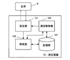
- FIG. 2 is a block diagram showing the configuration of the measuring apparatus 10 according to the present embodiment.
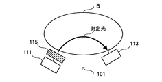
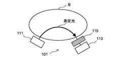
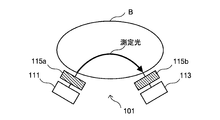
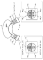
- 3A to 3C are explanatory diagrams showing an outline of the measurement unit according to the present embodiment.
- FIG. 4 is an explanatory diagram for explaining the measurement unit according to the present embodiment.
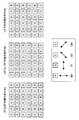
- 5 and 6 are explanatory diagrams for describing the polarization control unit according to the present embodiment.
- 7A and 7B are explanatory diagrams for describing the light source unit according to the present embodiment.
- 8 to 14 are explanatory diagrams showing specific examples of the measurement unit according to the present embodiment.
- FIG. 15 is an explanatory diagram for explaining the analysis processing in the analysis unit according to the present embodiment.
- the measuring apparatus 10 measures at least a part of the living body B, which is a measurement object, using at least one kind of measuring light having a predetermined wavelength, and based on the obtained measurement result, The concentration of the biological component contained inside is calculated.
- the measurement apparatus 10 controls the polarization direction of the measurement light, and calculates the optical rotation based on the detected change in the polarization state of the measurement light (change in the polarization direction).
- the measuring apparatus 10 calculates the concentration of the biological substance (for example, the concentration of blood components such as blood glucose, albumin, cholesterol, etc.) based on the calculated optical rotation.
- the measurement apparatus 10 not only the analysis of the concentration of the biological material based on the optical rotation but also the secondary calculation can be performed from the measurement result such as the scattering characteristic spectrum and the absorption spectrum obtained from the measurement result.
- the concentrations of various biological components can be specified by, for example, multivariate analysis.
- the measurement apparatus 10 mainly includes a measurement unit 101 that measures the measurement region of the living body B, a measurement control unit 103, an analysis unit 105, and a storage unit 107.
- the measurement unit 101 mainly includes a light source unit 111, a detection unit 113, and a polarization control unit 115.
- emits the measurement light which has at least 1 type of wavelength for measuring the biological component contained in the inside of a biological body.
- the wavelength of the measurement light emitted from the light source unit 111 can be set as appropriate according to the biological component of interest. For example, when measuring oxygenated hemoglobin, it is possible to use near infrared light with a wavelength of around 940 nm, and when measuring reduced hemoglobin, it is possible to use red light with a wavelength of around 660 nm. It is. Moreover, the knowledge regarding the fat which exists in a subcutaneous tissue can be acquired because the light source part 111 inject
- dye can be acquired because the light source part 111 inject
- Obtaining knowledge about glucose by emitting light with a plurality of characteristic wavelengths such as 1600 nm in a time-sharing manner and analyzing the obtained detection results using various analysis methods such as multivariate analysis be able to.
- Such light having a plurality of wavelengths is emitted from the light source unit 111 in a time division manner, for example.
- the various wavelengths described above are merely examples, and the light emitted from the light source unit 111 of the measurement apparatus 10 according to the present embodiment is not limited to the above examples.
- a light source unit 111 for example, a light emitting diode (LED), a small laser, or the like can be used, and one or a plurality of such light emitting devices are provided as the light source unit 111.
- LED light emitting diode
- small laser small laser
- the measurement control unit 103 controls the emission timing of the measurement light, the intensity of the measurement light to be emitted, switching of the light emitting device when there are a plurality of light emitting devices, and the like.
- the detection unit 113 detects the measurement light emitted from the inside of the living body B, converts the intensity of the detected measurement light into an electric signal, and outputs it to the analysis unit 105 described later.
- the detection unit 113 includes, for example, a CCD (Charge Coupled Devices) type image sensor, a CMOS (Complementary Metal Oxide Semiconductor) type image sensor, a sensor using an organic EL as a light receiving element, a TFT (Thin Film Transistor) type image sensor, and the like.
- a so-called image sensor such as a two-dimensional area sensor is used.
- microlens array image sensor having a microlens array (MLA) optical system in which a plurality of microlenses are arranged in a grid pattern.
- MLA microlens array
- a one-dimensional sensor such as a line sensor can be mounted on the detection unit 113.
- various detectors such as a photodiode (PD) and an InGaAs detector can be used as the detection unit 113.
- PD photodiode
- InGaAs detector InGaAs detector
- the detection unit 113 has scanning timing and the like controlled by a measurement control unit 103 described later, and can output the detection intensity of the measurement light to the analysis unit 105 at an arbitrary timing.
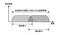
- the width of the wavelength band that can be detected by a detector is larger than the wavelength band required for measurement of the biological component of interest.
- Narrow cases can also occur.
- the detection unit 113 can be configured by using a combination of a plurality of types of detectors having different detectable wavelength band widths.
- the wavelength bands required for the measurement of biological components using two types of detectors that are different while overlapping the detectable wavelength bands. This is illustrated for securing.
- the polarization control unit 115 is an optical element capable of controlling the polarization direction of light used as measurement light, as represented by a polarizer such as a polarization filter, for example, and the measurement unit according to the present embodiment.
- a polarizer such as a polarization filter
- the measurement unit according to the present embodiment.
- at least two types of polarization control units 115 are used so that at least the measurement light becomes two types of plane polarized light orthogonal to each other.
- such a polarization control unit 115 is provided between the light source unit 111 and the living body (corresponding to FIG. 3A), between the living body and the detecting unit 113 (corresponding to FIG. 3B), Alternatively, they are provided both between the light source unit 111 and the living body and between the living body and the detection unit 113 (corresponding to FIG. 3C).
- the polarization control unit 115 such as a polarizing filter between the light source unit 111 and the living body, it is possible to irradiate the living body with surface polarized light having different polarization directions (at least two kinds of surface polarized light orthogonal to each other). It becomes possible. Further, by providing a polarization control unit 115 such as a polarization filter between the living body and the detector 113, the polarization direction of the measurement light emitted from the living body via the living body can be selected. It is possible to separately detect the measurement light beams having different polarization planes emitted by the detection unit 113. In addition, as shown in FIG.
- the polarization controller 115 between both the light source unit 111 and the living body and between the living body detection unit 113, the measurement light focused on as the measuring unit 101 can be measured. It is possible to further increase the number of combinations of polarization states.
- polarization control units 115 polarization filters or the like are used so that at least the measurement light becomes two types of plane-polarized light orthogonal to each other.
- plane polarized light different from the two types of plane polarized light orthogonal to each other can be obtained (in other words, orthogonal to each other).
- a polarization controller 115 capable of selecting another polarization direction may be used (so that two types of polarization directions are interpolated). That is, in the measurement unit 101 according to the present embodiment, a plurality of polarization filters can be appropriately combined so that an appropriate combination of polarizations can be realized in order to obtain measurement data effective for analysis.
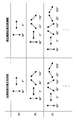
- FIG. 5 shows a combination example of polarization directions when a plurality of polarization controllers having different polarization directions are used.
- the polarization control unit 115 has two types of polarization filters (for example, 0 ° direction) so that at least the measurement light becomes two plane polarizations orthogonal to each other. And deflection filters corresponding to two kinds of polarization directions of 90 ° direction).
- the polarization direction positioned between the two types of directions so as to interpolate the two types of deflection directions orthogonal to each other.
- a polarizing filter capable of selecting the above may be further used.
- the polarizing filter corresponding to the 45 ° direction and the 135 ° direction in addition to the polarizing filter corresponding to the 0 ° direction and the polarizing filter corresponding to the 90 ° direction.
- the polarizing filter corresponding to in addition to the polarizing filter corresponding to the 0 ° direction and the polarizing filter corresponding to the 90 ° direction, it corresponds to 30 °, 60 °, 120 °, and 150 °.
- the case where a polarizing filter is used is shown.
- the polarization controller 115 provided between the light source unit 111 and the living body and the polarization controller 115 provided between the living body and the detector 113 are, for example, 0 °.
- the selectable polarization planes are set to be a pair, such as 0 °, 90 °, and 90 °.
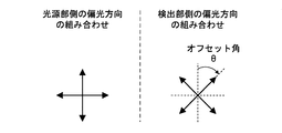
- the polarization direction selected by the polarization control unit 115 provided between the living body and the detection unit 113 is the light source unit 111 and the living body. May be set so as to be rotated by a predetermined offset angle with respect to the polarization direction selected by the polarization controller 115 provided therebetween.
- FIG. 6 by setting the polarization control units (polarization filters) 115 provided at two positions to be shifted, it is possible to select many polarization states while reducing the number of polarization filters to be used. It becomes possible.
- the installation angle of the polarization control unit 115 provided between the light source unit 111 and the living body is different from the installation angle of the polarization control unit 115 provided between the living body and the detection unit 113. Can be prevented from being blacked out by the polarization controller 115.
- the later-described analysis unit 105 it is possible to avoid a situation such as division by zero (that is, the calculation result becomes infinite) when performing calculation based on the signal strength. The accuracy can be improved.
- the measurement unit 101 according to this embodiment has been described in detail above with reference to FIGS. 3A to 6.
- control of polarized light having a plurality of wavelengths As described above, in the measurement unit 101 according to the present embodiment, measurement for analyzing concentrations of biological components using light of a plurality of wavelengths having a plurality of types of polarization planes. It can be used as light.
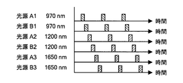
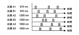
- a method for controlling measurement light having a plurality of wavelengths having a plurality of polarization planes will be briefly described with reference to FIGS. 7A and 7B.
- a case where measurement light having three types of wavelengths (970 nm, 1200 nm, and 1650 nm) having two types of polarization directions of polarization direction A and polarization direction B is used will be described as an example.
- the accuracy of the detection signal obtained is improved by switching the surface polarized light to be radiated at random as shown in FIG. 7B instead of switching with regularity as shown in FIG. 7A. Can be made. This is because data having a frequency higher than the sampling frequency can be detected by performing switching at random.
- the analysis unit 107 calculates the time change of the detection signal (that is, the pulse waveform, etc.) as the secondary information and uses it for the analysis of the biological component. The accuracy can be improved, and more accurate measurement can be performed.
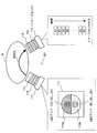
- the measurement unit 101 illustrated in FIG. 8 includes two units, an irradiation unit that irradiates a living body with measurement light, and a detection unit that detects measurement light emitted from the living body.
- the measurement unit 101 is a so-called reflection / scattering type measurement unit that detects measurement light emitted from a living body as a result of the measurement light scattered inside the living body B being reflected inside the living body. In such a reflection / scattering type measurement unit, the measurement light travels in a substantially U shape inside the living body B and is detected by the detection unit 113.
- two identical LED arrays capable of emitting n types of wavelengths 1 to n are used as the light source unit 111, and different polarization directions can be selected above each LED array.
- Various polarizing filters polarizing filters 115a and 115b are provided. Further, the measurement light transmitted through the polarizing filter 115 is irradiated toward the living body B after passing through the objective lens 117.
- the measurement light that has passed through the inside of the living body B in a substantially U-shaped path is polarized by the polarizing filter 115 on the detection unit 113 side (more specifically, the polarizing filters 115a and 115b similar to the polarizing filter on the light source unit 111 side). A direction is selected. Thereafter, the measurement light transmitted through the polarization filter 115 is collected by the objective lens 117 and formed on an image sensor that functions as the detection unit 113.
- the detection result is acquired for each plane polarization, and the detection result is output to the analysis unit 107.
- a light source group set in advance to have a predetermined plane polarization is provided.
- the group is electrically switched for use.
- an LED array (A1, A2,..., An) that can emit n types of measurement light having a certain polarization (for example, plane polarization in the 0 ° direction) and a polarization that is different from this LED array (for example, LED array (B1, B2,..., Bn) capable of emitting n types of measurement light having a plane direction of 90 °) can be realized.
- a certain polarization for example, plane polarization in the 0 ° direction
- a polarization that is different from this LED array for example, LED array (B1, B2,..., Bn) capable of emitting n types of measurement light having a plane direction of 90 °
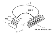
- a normal image sensor is used as the detection unit.
- a micro lens array (MLA) image sensor provided with a polarization filter 115 is used as the detection unit. It is also possible to do.
- the irradiation unit shown in FIG. 9 has the same configuration as the example shown in FIG.
- the MLA image sensor is an image sensor having a microlens array optical system.
- the microlens array is composed of a plurality of microlenses that are light receiving lenses, and each microlens is arranged in a lattice pattern on a predetermined substrate. Each microlens guides measurement light incident on the microlens to the image sensor.
- the microlens array is a lens array with little curvature of field and no distortion in the depth direction, good measurement data can be obtained by using such a microlens array.
- the depth of field of each microlens constituting the microlens array includes the skin structure to which attention is paid by the measurement apparatus 10 according to the present embodiment even when the living body B exists at the close-up distance. (For example, a range from the body surface to a depth of several millimeters to several tens of millimeters is focused).
- a light shield is provided between adjacent microlenses to control the directivity of light, and crosstalk of detection light between microlenses can be prevented. Further, it is possible to selectively acquire signals from one or a plurality of pixels of the image sensor corresponding to each microlens. Therefore, by using an MLA image sensor, it is possible to obtain a detection signal with excellent spatial resolution and temporal resolution.
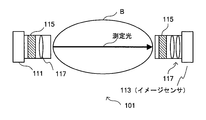
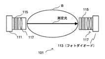
- FIG. 10 shows that the irradiation unit and the detection unit shown in FIG. 8 are arranged so as to face each other with the living body interposed therebetween, and are used as a transmission type measuring unit that detects measurement light completely transmitted through the inside of the living body B.
- a transmission type measuring unit that detects measurement light completely transmitted through the inside of the living body B.
- An example is shown. Even in the case of such a transmission type measurement unit, it is possible to use an MLA image sensor as shown in FIG.
- the measurement light passes through the living body by using the reflection / scattering type measurement unit as shown in FIGS.
- the length of the path can be shortened as compared with the transmission type.
- the image sensor is used as the detection unit 113.
- a photodiode PD
- FIG. 12 shows a specific example of the measurement unit 101 when a photodiode is used as the detection unit 113.
- the structure of the irradiation unit shown on the left side of FIG. 12 is the same as that of the irradiation unit shown in FIG.
- the detection unit of the measurement unit 101 shown in FIG. 12 includes a polarization filter 115 corresponding to the polarization filter 115 (polarization filters 115a and 115b) in the irradiation unit, an objective lens 117, And a photodiode functioning as the detection unit 113.
- two types of photodiodes PD_a and PD_b having different wavelength bands are used as the photodiodes as described in FIG.
- Two sets of photodiode groups each made up of these two types of photodiodes are used, and each photodiode group is arranged below the polarizing filters 115a and 115b.
- components of a certain polarization direction for example, plane polarization in the 0 ° direction
- the component of the polarization direction (for example, plane polarization in the 90 ° direction) is detected by the photodiodes PD_a and PD_b provided below the polarization filter 115b.
- a reflection / scattering type measurement unit is illustrated in the example shown in FIG. 12.
- the irradiation unit and the detection unit shown in FIG. It is also possible to arrange them in a transmission type measurement unit.
- the polarization filter is arranged as the polarization control unit 115 above the detection unit 113 .
- FIG. 14 for example, for each pixel of the image sensor. It is also possible to select the polarization direction of the received light. That is, as shown in FIG. 14, by arranging a polarization filter for each pixel, it is possible to simultaneously measure plane polarized light having different polarization planes with one image sensor.
- a combination of two kinds of polarization directions may be realized on the pixel of the image sensor, or on the pixel of the image sensor so that a combination of four kinds of polarization directions can be realized.
- a polarizing filter may be disposed on the surface.
- the polarization direction of the light used as the measurement light is electrically switched to be used for measurement of biological components. Therefore, compared to a measurement apparatus using a conventional non-invasive optical method. As a result, the device can be further downsized. Further, by adopting a reflection / scattering type optical system as the measurement unit 101, it is possible to further reduce the size of the apparatus and improve the convenience of the measurement subject.
- the measurement unit 101 included in the measurement apparatus 10 according to the present embodiment has been described in detail above with reference to FIGS.
- the measurement control unit 103 is realized by, for example, a CPU (Central Processing Unit), a ROM (Read Only Memory), a RAM (Random Access Memory), and the like.
- the measurement control unit 103 controls the whole measurement process of the living body B in the measurement unit 101 by performing drive control of the light source unit 111 and the detection unit 113 provided in the measurement unit 101, control of the polarization control unit 115, and the like. .
- the measurement control unit 103 performs drive control of the detection unit such as scanning timing of the detection unit 113 and selection of the detection unit 113 that acquires information based on a predetermined synchronization signal and the like. In addition, the measurement control unit 103 also performs switching control such as switching of the light source and drive control related to the emission timing and intensity of the measurement light with respect to the light source unit 111.
- the light source unit 111 of the measurement unit 101 can emit measurement light having different wavelengths and different polarization directions in a time-division manner, and on the detection unit 113. It is possible to obtain measurement data at any position of the time-division.
- Measurement data measured by the measurement unit 101 controlled by the measurement control unit 103 is output to the analysis unit 105 described later, and measurement data analysis processing is performed.
- control unit 103 can refer to various programs, parameters, databases, and the like recorded in the storage unit 107 to be described later when the measurement unit 101 is controlled.
- the analysis unit 105 included in the measurement apparatus 10 according to the present embodiment is realized by a CPU, a ROM, a RAM, and the like, for example.
- the analysis unit 105 calculates the optical rotation based on the change in the polarization state of the measurement light using the measurement result obtained by the measurement unit 101, and analyzes the concentration of the biological component based on the calculated optical rotation.
- the measurement unit 101 uses a polarization control unit 115 such as a polarization filter, and thereby uses a plane polarization component having a polarization direction defined by the polarization control unit 115 such as a polarization filter.
- the analysis unit 105 uses the ratio of the detected intensity of each plane-polarized light detected by the detection unit 113 (the ratio of the sensor gain), and the ratio of the light in what polarization direction. To determine if they are mixed.
- the analysis unit 105 performs vector calculation (vector synthesis processing) based on the obtained ratio and the vectors represented by the respective polarization directions defined by the polarization filter.
- vector calculation vector synthesis processing
- the analysis unit 105 obtains information about what polarization direction the measurement result of interest acquired from the measurement control unit 103 was measured by using measurement light (such as shown in FIGS. 7A and 7B).
- the optical rotation can be calculated based on the information obtained from the time-division timing chart) and the direction of the obtained polarization plane.
- the analysis unit 105 calculates the optical rotation by the method as described above, the analysis unit 105 refers to the specific rotation of the biological component of interest (for example, blood glucose, albumin, cholesterol, etc.) stored in the storage unit 107 or the like.
- the concentration of the biological component of interest is calculated based on Equation 10 above.
- the transmission distance L is calculated based on the light source unit 111 and the detection unit 113 in the measurement unit 101. It is possible to use a preset constant with reference to the separation distance between the two.
- the analysis unit 105 can obtain a scattering characteristic spectrum and an absorption spectrum by using respective measurement results when measuring light having various wavelengths is used. Therefore, the analysis unit 105 can calculate the concentrations of various biological components by further using such a scattering characteristic spectrum and absorption spectrum. At this time, the analysis unit 105 may calculate the concentration of the biological component of interest based on a predetermined arithmetic expression, or may calculate the concentration of the biological component of interest by performing so-called multivariate analysis. .
- the analysis unit 105 transmits the scattered light scattered inside the living body and the living body based on the polarization plane of the measuring light emitted toward the living body and the polarization plane of the measuring light emitted from the living body.
- Transmitted light in other words, light traveling straight through the living body
- Such separation of scattered light and transmitted light can be performed based on the polarization plane of the measurement light at each wavelength used as measurement light.
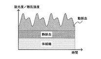
- the signal detected by the detection unit 113 after passing through the inside of the living body B from the light source unit 111 includes the amount of arterial blood that has been subjected to fluctuation due to arterial pulsation (pulse). Changes are included. Therefore, for example, as shown in FIG. 15, by extracting a quantitative change in arterial blood as a pulse waveform, the analysis unit 105 estimates blood oxygen saturation in the artery based on a known method. Can do.
- the measurement control unit 103 and the analysis unit 105 cooperate with each other to combine time-division sampling with a high-speed multi-wavelength light source by combining measurement light having a plurality of types of wavelengths, By injecting in a divided manner, the analysis unit 105 can also estimate the concentration of biological components in other arterial blood such as glucose. Specifically, the analysis unit 105 pays attention to the time change of the optical rotation calculated from the measurement result of the measurement light of each wavelength and the time change of the scattering characteristic spectrum, for example, as shown in FIG. Data representing the pulse waveform can be obtained. The analysis unit 105 uses the peak value and bottom value of the data representing the obtained pulse waveform, and the concentration of biological components in arterial blood (for example, glucose concentration, albumin concentration, cholesterol concentration, etc.) by a known method. Can be estimated.
- the storage unit 107 is realized by a RAM, a storage device, or the like provided in the measurement apparatus 10 according to the present embodiment.
- the storage unit 107 stores various data used for analysis processing in the analysis unit 105, various databases, a lookup table, and the like.
- the storage unit 107 stores measurement data measured by the measurement unit 101 according to the present embodiment, various programs and parameters used for processing performed by the measurement control unit 103 and the analysis unit 105 according to the present embodiment, and the like. Data or the like may be recorded.
- the storage unit 107 can appropriately store various parameters that need to be saved when the measurement apparatus 10 performs some processing, the progress of the processing, and the like. .
- the storage unit 107 can be freely accessed by each processing unit such as the measurement unit 101, the measurement control unit 103, and the analysis unit 105, and can write and read data.
- the measurement control unit 103 and the analysis unit 105 according to the present embodiment may be part of the measurement apparatus 10 according to the present embodiment, or may be realized in an external device such as a computer connected to the measurement apparatus 10. May be.
- measurement data generated by the measurement unit 101 is stored in a removable storage medium or the like, and this storage medium is removed from the measurement apparatus 10 and connected to another apparatus having the analysis unit 105, whereby the measurement data is stored. It may be analyzed.
- each component described above may be configured using a general-purpose member or circuit, or may be configured by hardware specialized for the function of each component.
- the CPU or the like may perform all functions of each component. Therefore, it is possible to appropriately change the configuration to be used according to the technical level at the time of carrying out the present embodiment.
- a computer program for realizing each function of the measuring apparatus according to the present embodiment as described above can be produced and mounted on a personal computer or the like.
- a computer-readable recording medium storing such a computer program can be provided.
- the recording medium is, for example, a magnetic disk, an optical disk, a magneto-optical disk, a flash memory, or the like.
- the above computer program may be distributed via a network, for example, without using a recording medium.
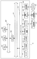
- FIG. 16 is a block diagram for describing a hardware configuration of the measurement apparatus 10 according to the embodiment of the present disclosure.
- the measuring apparatus 10 mainly includes a CPU 901, a ROM 903, and a RAM 905.
- the measurement apparatus 10 further includes a host bus 907, a bridge 909, an external bus 911, an interface 913, a sensor 914, an input device 915, an output device 917, a storage device 919, a drive 921, a connection port 923, and a communication device 925. .
- the CPU 901 functions as an arithmetic processing device and a control device, and controls all or a part of the operation in the measuring device 10 according to various programs recorded in the ROM 903, the RAM 905, the storage device 919, or the removable recording medium 927.
- the ROM 903 stores programs used by the CPU 901, calculation parameters, and the like.
- the RAM 905 primarily stores programs used by the CPU 901, parameters that change as appropriate during execution of the programs, and the like. These are connected to each other by a host bus 907 constituted by an internal bus such as a CPU bus.
- the host bus 907 is connected to an external bus 911 such as a PCI (Peripheral Component Interconnect / Interface) bus via a bridge 909.
- PCI Peripheral Component Interconnect / Interface
- the sensor 914 is, for example, detection means for detecting biological information unique to the user or various information used for acquiring such biological information.
- Examples of the sensor 914 include various image pickup devices such as a CCD (Charge Coupled Device) and a CMOS (Complementary Metal Oxide Semiconductor).
- the sensor 914 may further include an optical system such as a lens and a light source used for imaging a living body part.
- the sensor 914 may be a microphone or the like for acquiring sound or the like.
- the sensor 914 may include various measuring devices such as a thermometer, an illuminometer, a hygrometer, a speedometer, and an accelerometer in addition to the above-described ones.
- the input device 915 is an operation means operated by the user such as a mouse, a keyboard, a touch panel, a button, a switch, and a lever. Further, the input device 915 may be, for example, remote control means (so-called remote control) using infrared rays or other radio waves, or an external connection device 929 such as a mobile phone or a PDA corresponding to the operation of the measuring device 10. It may be. Furthermore, the input device 915 includes an input control circuit that generates an input signal based on information input by a user using the above-described operation means and outputs the input signal to the CPU 901, for example. The user of the measuring device 10 can input various data and instruct processing operations to the measuring device 10 by operating the input device 915.
- the output device 917 is a device that can notify the user of the acquired information visually or audibly. Examples of such devices include CRT display devices, liquid crystal display devices, plasma display devices, EL display devices and display devices such as lamps, audio output devices such as speakers and headphones, printer devices, mobile phones, and facsimiles.
- the output device 917 outputs, for example, results obtained by various processes performed by the measurement device 10. Specifically, the display device displays the results obtained by various processes performed by the measurement device 10 as text or images.
- the audio output device converts an audio signal composed of reproduced audio data, acoustic data, and the like into an analog signal and outputs the analog signal.
- the storage device 919 is a data storage device configured as an example of a storage unit of the measurement device 10.
- the storage device 919 includes, for example, a magnetic storage device such as an HDD (Hard Disk Drive), a semiconductor storage device, an optical storage device, or a magneto-optical storage device.
- the storage device 919 stores programs executed by the CPU 901, various data, various data acquired from the outside, and the like.
- the drive 921 is a reader / writer for a recording medium, and is built in or externally attached to the measuring apparatus 10.
- the drive 921 reads information recorded on a removable recording medium 927 such as a mounted magnetic disk, optical disk, magneto-optical disk, or semiconductor memory, and outputs the information to the RAM 905.
- the drive 921 can write a record on a removable recording medium 927 such as a magnetic disk, an optical disk, a magneto-optical disk, or a semiconductor memory.
- the removable recording medium 927 is, for example, a DVD medium, an HD-DVD medium, a Blu-ray medium, or the like.
- the removable recording medium 927 may be a compact flash (registered trademark) (CompactFlash: CF), a flash memory, or an SD memory card (Secure Digital memory card). Further, the removable recording medium 927 may be, for example, an IC card (Integrated Circuit card) on which a non-contact IC chip is mounted, an electronic device, or the like.
- CompactFlash CompactFlash: CF
- flash memory a flash memory
- SD memory card Secure Digital memory card
- the removable recording medium 927 may be, for example, an IC card (Integrated Circuit card) on which a non-contact IC chip is mounted, an electronic device, or the like.
- the connection port 923 is a port for directly connecting a device to the measurement apparatus 10.
- Examples of the connection port 923 include a USB (Universal Serial Bus) port, an IEEE 1394 port, a SCSI (Small Computer System Interface) port, and the like.
- As another example of the connection port 923 there are an RS-232C port, an optical audio terminal, an HDMI (High-Definition Multimedia Interface) port, and the like.
- the communication device 925 is a communication interface configured with, for example, a communication device for connecting to the communication network 931.
- the communication device 925 is, for example, a communication card for a wired or wireless LAN (Local Area Network), Bluetooth (registered trademark), or WUSB (Wireless USB).
- the communication device 925 may be a router for optical communication, a router for ADSL (Asymmetric Digital Subscriber Line), or a modem for various communication.
- the communication device 925 can transmit and receive signals and the like according to a predetermined protocol such as TCP / IP, for example, with the Internet or other communication devices.
- the communication network 931 connected to the communication device 925 is configured by a wired or wireless network, and may be, for example, the Internet, a home LAN, infrared communication, radio wave communication, satellite communication, or the like. .
- each component described above may be configured using a general-purpose member, or may be configured by hardware specialized for the function of each component. Therefore, it is possible to change the hardware configuration to be used as appropriate according to the technical level at the time of carrying out this embodiment.
- a light source unit that emits measurement light having at least one wavelength for measuring a biological component contained in the living body, a detection unit that detects the measurement light emitted from the inside of the living body, and the light source unit And a measurement unit having a polarization control unit that is provided between at least one of the living body or between the living body and the detection unit and controls a polarization direction of the measurement light;
- An analysis unit that calculates the optical rotation based on a change in the polarization state of the measurement light using a measurement result by the measurement unit, and analyzes the concentration of the biological component based on the calculated optical rotation;
- a measuring device that emits measurement light having at least one wavelength for measuring a biological component contained in the living body, a detection unit that detects the measurement light emitted from the inside of the living body, and the light source unit And a measurement unit having a polarization control unit that is provided between at least one of the living body or between the living body and the detection unit and controls a polarization direction of the measurement light;
- the measurement apparatus controls a polarization direction of the measurement light so that the measurement light becomes two types of plane polarized light orthogonal to each other.
- the measurement apparatus further includes a measurement control unit that controls the measurement unit, The measurement apparatus according to (1) or (2), wherein the measurement control unit switches a polarization direction of the measurement light in a time division manner.
- the analysis unit specifies a polarization direction of the measurement light detected using a ratio of detection intensity of each of the plane polarized lights detected by the detection unit, and calculates the optical rotation based on the specification result.
- the measuring apparatus according to any one of (3).
- the polarization control unit controls the polarization direction of the measurement light so that the polarization is different from the two types of plane polarization orthogonal to each other and different from the two types of plane polarization orthogonal to each other.
- the measuring apparatus according to any one of (4) to (4).
- the light source unit emits the measurement light having a plurality of different wavelengths from each other,
- the measurement control unit is configured to select the wavelength of the measurement light emitted from the light source unit and control the polarization direction of the measurement light by the polarization control unit in a time division manner.
- the measuring apparatus according to any one of (1) to (5), wherein a combination of polarization states is randomly changed.
- the polarization control unit is provided between the light source unit and the living body, and between the living body and the detection unit, The polarization direction selected by the polarization control unit provided between the living body and the detection unit is relative to the polarization direction selected by the polarization control unit provided between the light source unit and the living body.
- the measuring apparatus according to any one of (1) to (6), wherein the measuring apparatus is rotated by a predetermined offset angle.
- the measurement unit is a measurement unit that detects the measurement light emitted from the living body as a result of the measurement light scattered inside the living body being reflected inside the living body. Any one of (1) to (7) The measuring apparatus as described in any one.
- the light source unit emits the measurement light having a plurality of different wavelengths from each other
- the analysis unit obtains a pulse waveform representing a pulsation caused by a pulsation of an artery existing inside the living body based on a temporal change of the optical rotation obtained from a detection result of the measurement light at each wavelength.
- the measurement apparatus according to any one of (1) to (8), wherein the concentration of the biological component in arterial blood is calculated using the acquired peak value and bottom value of the pulse waveform.
- the light source unit emits the measurement light having a plurality of different wavelengths from each other,
- the analysis unit further calculates a concentration of the biological component by further using a scattering characteristic spectrum or an absorption spectrum obtained from the detection result of the measurement light at each wavelength, and any one of (1) to (8)
- the measuring apparatus according to one.
- the analysis unit generates a pulse waveform representing a pulsation caused by a pulsation of an artery existing inside the living body based on a temporal change of the scattering characteristic spectrum obtained from the detection result of the measurement light at each wavelength.
- the measurement apparatus according to (10), wherein the concentration is acquired and the concentration of the biological component in arterial blood is calculated using the acquired peak value and bottom value of the pulse waveform.
- the measurement apparatus according to any one of (1) to (11), wherein the analysis unit calculates a blood glucose concentration.
- the analysis unit based on a polarization plane of the measurement light emitted toward the living body and a polarization plane of the measurement light emitted from the living body, scattered light scattered inside the living body, The measuring apparatus according to any one of (1) to (12), wherein the transmitted light transmitted through the living body is separated.
- the light source unit emits the measurement light having a plurality of different wavelengths from each other, The measurement device according to (13), wherein the analysis unit separates the scattered light and the transmitted light based on a polarization plane of the measurement light at each wavelength.
- a light source unit that emits measurement light having at least one wavelength for measuring a biological component contained in the living body, a detection unit that detects the measurement light emitted from the inside of the living body, and the light source unit
- a computer capable of communicating with a measuring instrument provided between at least one of the living body or between the living body and the detection unit and having a polarization control unit that controls the polarization direction of the measurement light;
- a light source unit that emits measurement light having at least one wavelength for measuring a biological component contained in the living body, a detection unit that detects the measurement light emitted from the inside of the living body, and the light source unit And a measurement unit having a polarization control unit that is provided between at least one of the living body or between the living body and the detection unit and controls a polarization direction of the measurement light;
- An analysis unit that calculates the optical rotation based on a change in the polarization state of the measurement light using a measurement result by the measurement unit, and analyzes the concentration of the biological component based on the calculated optical rotation;
- a measurement control unit for controlling the measurement unit; With The measurement unit is a measurement unit that detects the measurement light emitted from the living body as a result of the measurement light scattered inside the living body being reflected inside the living body,
- the measurement control unit is a measurement device that switches the polarization direction of the measurement light in a time-sharing manner.
- a light source unit that emits measurement light having at least one wavelength for measuring a biological component contained in the living body, a detection unit that detects the measurement light emitted from the inside of the living body, and the light source unit And a living body, or at least one of the living body and the detection unit, and has a polarization control unit that controls the polarization direction of the measurement light, and is scattered inside the living body.
- a computer capable of communicating with the measuring device that detects the measurement light emitted from the living body, An analysis function for calculating the optical rotation based on the change in the polarization state of the measurement light using the measurement result by the measuring device, and analyzing the concentration of the biological component based on the calculated optical rotation; A control function of the measuring instrument; A program to realize
Abstract
Provided are a measurement device, measurement method, program, and recording medium that allow further miniaturization of the device. This measurement device is provided with a measurement unit and an analysis unit. The measurement unit has the following: a light-source unit that emits measuring light having at least one wavelength for measuring a biological component inside a body; a detection unit that detects measuring light emitted from inside the body; and a polarization control unit that controls the polarization direction of the measuring light and is provided between the light-source unit and the body and/or between the body and the detection unit. The analysis unit uses measurement results from the measurement unit to compute an optical rotation on the basis of the change in the polarization state of the measuring light and analyzes the concentration of the abovementioned biological component on the basis of the computed optical rotation.
Description
本開示は、測定装置、測定方法、プログラム及び記録媒体に関する。
The present disclosure relates to a measuring device, a measuring method, a program, and a recording medium.
生体の皮下に存在する体内物質や血液中に含まれる血中成分(生体成分)を、各種の光を用いて非侵襲で計測する技術に関する研究が進んでいる。このような非侵襲光学方式による生体成分の分析技術では、一般的に、光吸収率を利用して生体成分の濃度を特定することが行われてきた(例えば、以下の特許文献1を参照。)。
Research on techniques for non-invasive measurement of body substances existing in the skin of a living body and blood components (biological components) contained in blood using various types of light is in progress. In such a biological component analysis technique using a non-invasive optical method, generally, the concentration of the biological component has been specified using the light absorption rate (see, for example, Patent Document 1 below). ).
ここで、上記特許文献1に示したような生体成分濃度測定装置では、生体を透過した光(透過光)の強度に基づいて生体成分の濃度が測定されるものであるが、生体は光を良く散乱させる物体であるとともに、生体内に含まれるそれぞれの生体成分により照射した光の一部が吸収されてしまうため、照射する光の強度によっては、十分な透過光が得られない可能性がある。従って、上記特許文献1に示したような非侵襲光学方式を利用した生体成分濃度測定装置では、十分な強度の光を射出可能な光源や、微弱な透過光を検出可能な検出器を用いることが好ましく、装置が大型化する傾向があった。また、生体成分として血中グルコース濃度を測定する場合には、透過光の散乱特性や透過光の脈動による変化を計測する必要があり、装置が大掛かりなものとなってしまう。そのため、検出精度を維持しつつ、装置の小型化を図ることが求められている。
Here, in the biological component concentration measuring apparatus as shown in Patent Document 1, the concentration of the biological component is measured based on the intensity of light (transmitted light) that has passed through the living body. It is an object that scatters well, and part of the irradiated light is absorbed by each biological component contained in the living body, so there is a possibility that sufficient transmitted light cannot be obtained depending on the intensity of the irradiated light is there. Therefore, in the biological component concentration measuring apparatus using the non-invasive optical method as shown in Patent Document 1, a light source capable of emitting light with sufficient intensity and a detector capable of detecting weak transmitted light are used. The device tends to be large. Further, when measuring blood glucose concentration as a biological component, it is necessary to measure changes due to scatter of transmitted light and pulsation of transmitted light, which makes the apparatus large. Therefore, it is required to reduce the size of the apparatus while maintaining the detection accuracy.
そこで、本開示では、上記事情に鑑みて、装置の更なる小型化を図ることが可能な測定装置、測定方法、プログラム及び記録媒体を提案する。
Therefore, in view of the above circumstances, the present disclosure proposes a measuring device, a measuring method, a program, and a recording medium that can further reduce the size of the device.
本開示によれば、生体の内部に含まれる生体成分を測定するための少なくとも1種の波長を有する測定光を射出する光源部、前記生体の内部から射出された前記測定光を検出する検出部、及び、前記光源部と前記生体との間、又は、前記生体と前記検出部との間の少なくとも何れか一方に設けられ、前記測定光の偏光方向を制御する偏光制御部を有する測定部と、前記測定部による測定結果を利用して前記測定光の偏光状態の変化に基づいて旋光度を算出し、算出した前記旋光度に基づいて前記生体成分の濃度を解析する解析部と、を備える測定装置が提供される。
According to the present disclosure, a light source unit that emits measurement light having at least one wavelength for measuring a biological component contained in a living body, and a detection unit that detects the measurement light emitted from the inside of the living body And a measurement unit having a polarization control unit that is provided between at least one of the light source unit and the living body or between the living body and the detection unit and controls the polarization direction of the measurement light. An analysis unit that calculates an optical rotation based on a change in a polarization state of the measurement light using a measurement result by the measurement unit, and analyzes a concentration of the biological component based on the calculated optical rotation A measuring device is provided.
また、本開示によれば、生体の内部に含まれる生体成分を測定するための少なくとも1種の波長を有する測定光を射出することと、前記測定光の光源と前記生体との間、又は、前記生体の内部から射出された前記測定光を検出する検出部と前記生体との間の少なくとも何れか一方の位置で、前記測定光の偏光方向を制御することと、前記生体の内部から射出された前記測定光を検出することと、前記測定光の検出結果を利用して前記測定光の偏光状態の変化に基づいて旋光度を算出し、算出した前記旋光度に基づいて前記生体成分の濃度を解析することと、を含む測定方法が提供される。
Further, according to the present disclosure, emitting measurement light having at least one wavelength for measuring a biological component contained in a living body, between the light source of the measuring light and the living body, or Controlling the polarization direction of the measurement light at at least one of the position between the living body and the detection unit for detecting the measurement light emitted from the inside of the living body; Detecting the measurement light, and calculating the optical rotation based on a change in the polarization state of the measurement light using the detection result of the measurement light, and the concentration of the biological component based on the calculated optical rotation And a measurement method is provided.
また、本開示によれば、生体の内部に含まれる生体成分を測定するための少なくとも1種の波長を有する測定光を射出する光源部、前記生体の内部から射出された前記測定光を検出する検出部、及び、前記光源部と前記生体との間、又は、前記生体と前記検出部との間の少なくとも何れか一方に設けられ、前記測定光の偏光方向を制御する偏光制御部を有する測定機器と通信可能なコンピュータに、前記測定機器による測定結果を利用して前記測定光の偏光状態の変化に基づいて旋光度を算出し、算出した前記旋光度に基づいて前記生体成分の濃度を解析する解析機能を実現させるためのプログラムが提供される。
According to the present disclosure, a light source unit that emits measurement light having at least one wavelength for measuring a biological component contained in the living body, and the measurement light emitted from the living body is detected. Measurement having a detection unit and a polarization control unit that is provided between at least one of the light source unit and the living body or between the living body and the detection unit and controls the polarization direction of the measurement light. Calculates the optical rotation based on the change in the polarization state of the measurement light using a measurement result of the measurement device, and analyzes the concentration of the biological component based on the calculated optical rotation on a computer capable of communicating with the device A program for realizing the analysis function is provided.
また、本開示によれば、生体の内部に含まれる生体成分を測定するための少なくとも1種の波長を有する測定光を射出する光源部、前記生体の内部から射出された前記測定光を検出する検出部、及び、前記光源部と前記生体との間、又は、前記生体と前記検出部との間の少なくとも何れか一方に設けられ、前記測定光の偏光方向を制御する偏光制御部を有する測定機器と通信可能なコンピュータに、前記測定機器による測定結果を利用して前記測定光の偏光状態の変化に基づいて旋光度を算出し、算出した前記旋光度に基づいて前記生体成分の濃度を解析する解析機能を実現させるためのプログラムが記録された記録媒体が提供される。
According to the present disclosure, a light source unit that emits measurement light having at least one wavelength for measuring a biological component contained in the living body, and the measurement light emitted from the living body is detected. Measurement having a detection unit and a polarization control unit that is provided between at least one of the light source unit and the living body or between the living body and the detection unit and controls the polarization direction of the measurement light. Calculates the optical rotation based on the change in the polarization state of the measurement light using a measurement result of the measurement device, and analyzes the concentration of the biological component based on the calculated optical rotation on a computer capable of communicating with the device A recording medium on which a program for realizing the analysis function is recorded is provided.
また、本開示によれば、生体の内部に含まれる生体成分を測定するための少なくとも1種の波長を有する測定光を射出する光源部、前記生体の内部から射出された前記測定光を検出する検出部、及び、前記光源部と前記生体との間、又は、前記生体と前記検出部との間の少なくとも何れか一方に設けられ、前記測定光の偏光方向を制御する偏光制御部を有する測定部と、前記測定部による測定結果を利用して前記測定光の偏光状態の変化に基づいて旋光度を算出し、算出した前記旋光度に基づいて前記生体成分の濃度を解析する解析部と、前記測定部の制御を行う測定制御部と、を備え、前記測定部は、前記生体の内部で散乱した前記測定光が当該生体の内部で反射した結果前記生体から射出される前記測定光を検出する測定ユニットであり、前記測定制御部は、前記測定光の偏光方向を時分割で切り替えさせる測定装置が提供される。
According to the present disclosure, a light source unit that emits measurement light having at least one wavelength for measuring a biological component contained in the living body, and the measurement light emitted from the living body is detected. Measurement having a detection unit and a polarization control unit that is provided between at least one of the light source unit and the living body or between the living body and the detection unit and controls the polarization direction of the measurement light. And an analysis unit that calculates the optical rotation based on a change in the polarization state of the measurement light using a measurement result by the measurement unit, and analyzes the concentration of the biological component based on the calculated optical rotation, A measurement control unit that controls the measurement unit, and the measurement unit detects the measurement light emitted from the living body as a result of the measurement light scattered inside the living body being reflected inside the living body. Measurement unit The measurement control unit, to switch in a time division polarization direction of the measurement light measuring device is provided.
また、本開示によれば、生体の内部に含まれる生体成分を測定するための少なくとも1種の波長を有する測定光を射出することと、前記測定光の光源と前記生体との間、又は、前記生体の内部から射出された前記測定光を検出する検出部と前記生体との間の少なくとも何れか一方の位置で、前記測定光の偏光方向を制御することと、前記生体の内部から射出された前記測定光を検出することと、前記測定光の検出結果を利用して前記測定光の偏光状態の変化に基づいて旋光度を算出し、算出した前記旋光度に基づいて前記生体成分の濃度を解析することと、を含み、前記測定光の射出及び検出は、前記生体の内部で散乱した前記測定光が当該生体の内部で反射した結果前記生体から射出される前記測定光を検出する測定ユニットにより行われ、前記測定光の偏光方向は、時分割で切り替えられる、測定方法が提供される。
Further, according to the present disclosure, emitting measurement light having at least one wavelength for measuring a biological component contained in a living body, between the light source of the measuring light and the living body, or Controlling the polarization direction of the measurement light at at least one of the position between the living body and the detection unit for detecting the measurement light emitted from the inside of the living body; Detecting the measurement light, and calculating the optical rotation based on a change in the polarization state of the measurement light using the detection result of the measurement light, and the concentration of the biological component based on the calculated optical rotation And measuring and detecting the measurement light emitted from the living body as a result of the measurement light scattered inside the living body being reflected inside the living body. Done by unit , The polarization direction of the measurement light, when switched division, the measurement method is provided.
また、本開示によれば、生体の内部に含まれる生体成分を測定するための少なくとも1種の波長を有する測定光を射出する光源部、前記生体の内部から射出された前記測定光を検出する検出部、及び、前記光源部と前記生体との間、又は、前記生体と前記検出部との間の少なくとも何れか一方に設けられ、前記測定光の偏光方向を制御する偏光制御部を有し、生体の内部で散乱した前記測定光が当該生体の内部で反射した結果前記生体から射出される前記測定光を検出する測定機器と通信可能なコンピュータに、前記測定機器による測定結果を利用して前記測定光の偏光状態の変化に基づいて旋光度を算出し、算出した前記旋光度に基づいて前記生体成分の濃度を解析する解析機能と、前記測定機器の制御機能と、を実現させるためのプログラムが提供される。
According to the present disclosure, a light source unit that emits measurement light having at least one wavelength for measuring a biological component contained in the living body, and the measurement light emitted from the living body is detected. A detection unit, and a polarization control unit that is provided between at least one of the light source unit and the living body, or between the living body and the detection unit, and controls the polarization direction of the measurement light. The measurement light scattered inside the living body is reflected inside the living body, and as a result, the computer can communicate with the measuring equipment that detects the measurement light emitted from the living body. An optical rotation is calculated based on a change in the polarization state of the measurement light, and an analysis function for analyzing the concentration of the biological component based on the calculated optical rotation and a control function for the measurement instrument are realized. Professional Lamb is provided.
本開示によれば、光源部から射出された測定光が生体から射出されて検出部によって検出されるまでの間に、偏光制御部により測定光の偏光方向が制御される。また、解析部は、測定部により測定された測定結果を利用し、測定光の偏光状態の変化に基づいて旋光度を算出し、算出した旋光度に基づいて生体成分の濃度を解析する。
According to the present disclosure, the polarization direction of the measurement light is controlled by the polarization control unit until the measurement light emitted from the light source unit is emitted from the living body and detected by the detection unit. The analysis unit calculates the optical rotation based on the change in the polarization state of the measurement light using the measurement result measured by the measurement unit, and analyzes the concentration of the biological component based on the calculated optical rotation.
以上説明したように本開示によれば、装置の更なる小型化を図ることが可能である。
As described above, according to the present disclosure, it is possible to further reduce the size of the apparatus.
以下に添付図面を参照しながら、本開示の好適な実施の形態について詳細に説明する。なお、本明細書及び図面において、実質的に同一の機能構成を有する構成要素については、同一の符号を付することにより重複説明を省略する。
Hereinafter, preferred embodiments of the present disclosure will be described in detail with reference to the accompanying drawings. In addition, in this specification and drawing, about the component which has the substantially same function structure, duplication description is abbreviate | omitted by attaching | subjecting the same code | symbol.
なお、説明は、以下の順序で行うものとする。
(1)旋光度に基づく濃度測定の原理について
(2)第1の実施形態
(2-1)測定装置の構成について
(3)本開示の実施形態に係る測定装置のハードウェア構成について The description will be made in the following order.
(1) Principle of concentration measurement based on optical rotation (2) First embodiment (2-1) Configuration of measurement device (3) Hardware configuration of measurement device according to embodiment of present disclosure
(旋光度に基づく濃度測定の原理について)
本開示の実施形態に係る測定装置、測定方法、プログラム及び記録媒体について説明するに先立ち、以下では、図1を参照しながら、旋光度に基づく濃度測定の原理について、簡単に説明する。図1は、旋光度に基づく濃度測定の原理について説明するための説明図である。 (About the principle of concentration measurement based on optical rotation)
Prior to describing the measurement apparatus, measurement method, program, and recording medium according to the embodiment of the present disclosure, the principle of concentration measurement based on the optical rotation will be briefly described below with reference to FIG. FIG. 1 is an explanatory diagram for explaining the principle of concentration measurement based on optical rotation.
光は電磁波の一種であるが、光を含む電磁波は、進行方向に対して垂直な様々な方向(例えば、縦方向、横方向、斜め方向等)に振動している横波として考えることができる。このような様々な方向に振動している光の中には、特定の方向に振動しているものも存在しうる。このような特定の方向に振動している光は、偏光と呼ばれる。このような偏光の一種として、振動方向が光の伝播に伴って円を描く円偏光や、特定の方向にのみ振動している平面偏光(面偏光ともいう。)等が存在する。また、上記円偏光には、回転方向(時計回りか反時計回りか)に応じて、右円偏光と左円偏光という2種類の円偏光が存在することが知られている。また、平面偏光は、全く同じ振動と周期で進行している右円偏光と左円偏光のベクトル和として考えることができる。
Although light is a kind of electromagnetic wave, an electromagnetic wave including light can be considered as a transverse wave oscillating in various directions perpendicular to the traveling direction (for example, a vertical direction, a horizontal direction, an oblique direction, etc.). Among such light oscillating in various directions, there may be light oscillating in a specific direction. Such light oscillating in a specific direction is called polarized light. As one type of such polarized light, there is circular polarized light whose vibration direction forms a circle as light propagates, planar polarized light (also referred to as plane polarized light) that vibrates only in a specific direction, and the like. In addition, it is known that the circularly polarized light includes two types of circularly polarized light, right circularly polarized light and left circularly polarized light, depending on the rotation direction (clockwise or counterclockwise). Further, the plane polarized light can be considered as a vector sum of right circularly polarized light and left circularly polarized light traveling with exactly the same vibration and period.
いま、図1に示したように、ある光源から円偏光の光が射出されたものとする。この円偏光の光路中に、特定の偏光(例えば、縦方向にのみ振動している光)を取り出すことが可能な光学素子である偏光子(偏光フィルタ)が設置されると、偏光フィルタを透過できる光は、図1に示したように、縦方向にのみ振動している面偏光のみとなる。
Now, as shown in FIG. 1, it is assumed that circularly polarized light is emitted from a certain light source. When a polarizer (polarization filter), which is an optical element that can extract specific polarized light (for example, light that vibrates only in the longitudinal direction), is installed in the optical path of this circularly polarized light, it passes through the polarizing filter. As shown in FIG. 1, the light that can be generated is only plane polarized light that vibrates only in the vertical direction.
ここで、図1に示したように、面偏光がある物質(測定物質)に入射した場合を考える。測定物質が、グルコース等のように不斉炭素を有する物質の溶液であったり、偏極面を有する結晶等の固体であったりすると、面偏光と測定物質との間で相互作用が生じて、物質内を進む右円偏光の速度と左円偏光の速度とが異なってしまう場合が生じうる。この場合、右円偏光と左円偏光とのベクトル和として考えられる面偏光の偏光面は、入射した際の偏光面から角度αだけ回転してしまうこととなる。この場合に、右円偏光の速度が左円偏光の速度よりも大きい場合には、物質を射出した際の偏光面は、入射した際の偏光面から右に回転することとなり、左円偏光の速度が右円偏光の速度よりも大きい場合には、物質を射出した際の偏光面は、入射した際の偏光面から左に回転することとなる。このような現象は旋光と呼ばれ、回転した角度αは、旋光度と呼ばれている。
Here, as shown in FIG. 1, consider a case where the light is incident on a substance having a surface polarization (measurement substance). When the measurement substance is a solution of a substance having an asymmetric carbon such as glucose or a solid such as a crystal having a polarized surface, an interaction occurs between the plane polarized light and the measurement substance, There may be a case where the speed of right circularly polarized light traveling in the material differs from the speed of left circularly polarized light. In this case, the plane of polarization of plane-polarized light that can be considered as the vector sum of right-handed circularly polarized light and left-handed circularly-polarized light is rotated by an angle α from the plane of polarization when incident. In this case, when the speed of the right circularly polarized light is larger than the speed of the left circularly polarized light, the polarization plane when the material is emitted rotates to the right from the polarization plane when the material is incident. When the velocity is larger than the velocity of right-handed circularly polarized light, the plane of polarization when the substance is emitted rotates to the left from the plane of polarization when incident. Such a phenomenon is called optical rotation, and the rotated angle α is called optical rotation.
ここで、検出器により測定される旋光度αの大きさは、着目している物質に固有の定数(比旋光度)と、着目している物質の濃度と、透過距離と、を利用して、以下の式10で表されることが知られている。
Here, the magnitude of the optical rotation α measured by the detector is obtained by using a constant (specific optical rotation) specific to the target substance, the concentration of the target substance, and the transmission distance. It is known that it is represented by the following formula 10.

ここで、上記式10において、
α(λ):波長λの面偏光により測定した温度tにおける物質の旋光度の実測値
[α]t λ:波長λの面偏光により測定した温度tにおける物質の比旋光度
C:物質の濃度[g/ml]
L:透過距離[mm]
である。 Here, inEquation 10 above,
α (λ): Measured value of optical rotation of substance at temperature t measured by plane polarization with wavelength λ [α] t λ : Specific rotation of substance at temperature t measured with plane polarization of wavelength λ C: Concentration of substance [G / ml]
L: Transmission distance [mm]
It is.
α(λ):波長λの面偏光により測定した温度tにおける物質の旋光度の実測値
[α]t λ:波長λの面偏光により測定した温度tにおける物質の比旋光度
C:物質の濃度[g/ml]
L:透過距離[mm]
である。 Here, in
α (λ): Measured value of optical rotation of substance at temperature t measured by plane polarization with wavelength λ [α] t λ : Specific rotation of substance at temperature t measured with plane polarization of wavelength λ C: Concentration of substance [G / ml]
L: Transmission distance [mm]
It is.
上記のように比旋光度は物質に固有の値であるため、物質中を光が進んだ長さ(上記式10におけるパラメータL)と、旋光度の実測値とを得ることができれば、上記式10を利用して着目する測定物質の濃度を特定することが可能となる。
As described above, the specific rotation is a value inherent to the substance. Therefore, if it is possible to obtain the length of light traveled through the substance (parameter L in Expression 10 above) and the actual measured value of the optical rotation, the above expression can be obtained. 10 can be used to specify the concentration of the target measurement substance.
以下で説明する本開示の実施形態に係る測定装置では、上記式10で表される旋光度に着目し、偏光を利用して生体を測定した測定結果を利用して、測定に用いた偏光(測定光)の偏光状態の変化から旋光度を算出する。その上で、本開示の実施形態に係る測定装置は、算出した旋光度に基づいて生体物質の濃度を特定する。
In the measurement apparatus according to the embodiment of the present disclosure described below, paying attention to the optical rotation expressed by the above formula 10, using the measurement result obtained by measuring the living body using the polarization, the polarization ( The optical rotation is calculated from the change in the polarization state of the measurement light. In addition, the measurement device according to the embodiment of the present disclosure specifies the concentration of the biological substance based on the calculated optical rotation.
(第1の実施形態)
<測定装置の構成について>
続いて、図2~図15を参照しながら、本開示の第1の実施形態に係る測定装置及び測定方法について、詳細に説明する。図2は、本実施形態に係る測定装置10の構成について示したブロック図である。図3A~図3Cは、本実施形態に係る測定部の概略を示した説明図である。図4は、本実施形態に係る測定部について説明するための説明図である。図5及び図6は、本実施形態に係る偏光制御部について説明するための説明図である。図7A及び図7Bは、本実施形態に係る光源部について説明するための説明図である。図8~図14は、本実施形態に係る測定部の具体例を示した説明図である。図15は、本実施形態に係る解析部における解析処理について説明するための説明図である。 (First embodiment)
<About the configuration of the measuring device>
Subsequently, the measurement apparatus and the measurement method according to the first embodiment of the present disclosure will be described in detail with reference to FIGS. FIG. 2 is a block diagram showing the configuration of the measuringapparatus 10 according to the present embodiment. 3A to 3C are explanatory diagrams showing an outline of the measurement unit according to the present embodiment. FIG. 4 is an explanatory diagram for explaining the measurement unit according to the present embodiment. 5 and 6 are explanatory diagrams for describing the polarization control unit according to the present embodiment. 7A and 7B are explanatory diagrams for describing the light source unit according to the present embodiment. 8 to 14 are explanatory diagrams showing specific examples of the measurement unit according to the present embodiment. FIG. 15 is an explanatory diagram for explaining the analysis processing in the analysis unit according to the present embodiment.
<測定装置の構成について>
続いて、図2~図15を参照しながら、本開示の第1の実施形態に係る測定装置及び測定方法について、詳細に説明する。図2は、本実施形態に係る測定装置10の構成について示したブロック図である。図3A~図3Cは、本実施形態に係る測定部の概略を示した説明図である。図4は、本実施形態に係る測定部について説明するための説明図である。図5及び図6は、本実施形態に係る偏光制御部について説明するための説明図である。図7A及び図7Bは、本実施形態に係る光源部について説明するための説明図である。図8~図14は、本実施形態に係る測定部の具体例を示した説明図である。図15は、本実施形態に係る解析部における解析処理について説明するための説明図である。 (First embodiment)
<About the configuration of the measuring device>
Subsequently, the measurement apparatus and the measurement method according to the first embodiment of the present disclosure will be described in detail with reference to FIGS. FIG. 2 is a block diagram showing the configuration of the measuring
まず、図2を参照しながら、本実施形態に係る測定装置10の全体構成について、詳細に説明する。
本実施形態に係る測定装置10は、測定対象物である生体Bの少なくとも一部を所定の波長を有する少なくとも1種の測定光を用いて測定し、得られた測定結果に基づいて、生体の内部に含まれる生体成分の濃度を算出する。この際、測定装置10では、測定光の偏光方向を制御しており、検出された測定光の偏光状態の変化(偏光方向の変化)に基づいて旋光度を算出する。その上で、測定装置10は、算出した旋光度に基づいて生体物質の濃度(例えば、血中グルコースや、アルブミンや、コレステロール等といった血中成分の濃度)を算出する。 First, the overall configuration of themeasurement apparatus 10 according to the present embodiment will be described in detail with reference to FIG.
The measuringapparatus 10 according to the present embodiment measures at least a part of the living body B, which is a measurement object, using at least one kind of measuring light having a predetermined wavelength, and based on the obtained measurement result, The concentration of the biological component contained inside is calculated. At this time, the measurement apparatus 10 controls the polarization direction of the measurement light, and calculates the optical rotation based on the detected change in the polarization state of the measurement light (change in the polarization direction). Then, the measuring apparatus 10 calculates the concentration of the biological substance (for example, the concentration of blood components such as blood glucose, albumin, cholesterol, etc.) based on the calculated optical rotation.
本実施形態に係る測定装置10は、測定対象物である生体Bの少なくとも一部を所定の波長を有する少なくとも1種の測定光を用いて測定し、得られた測定結果に基づいて、生体の内部に含まれる生体成分の濃度を算出する。この際、測定装置10では、測定光の偏光方向を制御しており、検出された測定光の偏光状態の変化(偏光方向の変化)に基づいて旋光度を算出する。その上で、測定装置10は、算出した旋光度に基づいて生体物質の濃度(例えば、血中グルコースや、アルブミンや、コレステロール等といった血中成分の濃度)を算出する。 First, the overall configuration of the
The measuring
また、本実施形態に係る測定装置10では、旋光度に基づく生体物質の濃度の解析のみならず、測定結果から得られる散乱特性スペクトルや吸収スペクトル等といった、測定結果から二次的に算出可能な情報を利用して、様々な生体成分の濃度を例えば多変量解析等により特定することも可能である。
Further, in the measurement apparatus 10 according to the present embodiment, not only the analysis of the concentration of the biological material based on the optical rotation but also the secondary calculation can be performed from the measurement result such as the scattering characteristic spectrum and the absorption spectrum obtained from the measurement result. Using information, it is also possible to specify the concentrations of various biological components by, for example, multivariate analysis.
この測定装置10は、図2に示したように、生体Bの測定領域を測定する測定部101と、測定制御部103と、解析部105と、記憶部107と、を主に備える。
2, the measurement apparatus 10 mainly includes a measurement unit 101 that measures the measurement region of the living body B, a measurement control unit 103, an analysis unit 105, and a storage unit 107.
[測定部101について]
以下では、まず、図3~図14を参照しながら、本実施形態に係る測定部101の構成について、具体的に説明する。
本実施形態に係る測定部101は、図3A~図3Cに示したように、光源部111と、検出部113と、偏光制御部115と、を主に備える。 [About measuring unit 101]
Hereinafter, first, the configuration of themeasurement unit 101 according to the present embodiment will be specifically described with reference to FIGS. 3 to 14.
As shown in FIGS. 3A to 3C, themeasurement unit 101 according to the present embodiment mainly includes a light source unit 111, a detection unit 113, and a polarization control unit 115.
以下では、まず、図3~図14を参照しながら、本実施形態に係る測定部101の構成について、具体的に説明する。
本実施形態に係る測定部101は、図3A~図3Cに示したように、光源部111と、検出部113と、偏光制御部115と、を主に備える。 [About measuring unit 101]
Hereinafter, first, the configuration of the
As shown in FIGS. 3A to 3C, the
○光源部について
光源部111は、生体の内部に含まれる生体成分を測定するための少なくとも1種の波長を有する測定光を射出するものである。 About light source part Thelight source part 111 inject | emits the measurement light which has at least 1 type of wavelength for measuring the biological component contained in the inside of a biological body.
光源部111は、生体の内部に含まれる生体成分を測定するための少なくとも1種の波長を有する測定光を射出するものである。 About light source part The
光源部111が射出する測定光の波長は、着目する生体成分に応じて適宜設定することが可能である。例えば、酸素化ヘモグロビンを測定する場合には、波長940nm前後の近赤外光を使用することが可能であり、還元ヘモグロビンを測定する場合には、波長660nm前後の赤色光を使用することが可能である。また、光源部111が940nm、950nmのような波長の光を射出することで、皮下組織に存在する脂肪に関する知見を得ることができる。また、光源部111が568nm、580nm、660nm、890nmのような波長の光を射出することで、メラニン色素に関する知見を得ることができる。また、光源部111が、一般的に知られているグルコースの特徴的なスペクトルのピークである970nm、1160nm、1250nm、1400nm付近、1550nm、1650nm、2200nm、あるいはボトムとしての特徴である1200nm、1300nm付近、1600nm等の複数の特徴的な波長の光を時間分割的に射出し、得られた検出結果を、例えば多変量解析等といった各種の解析手法を用いて解析することで、グルコースに関する知見を得ることができる。このような複数の波長の光は、例えば、光源部111から時分割で射出される。
The wavelength of the measurement light emitted from the light source unit 111 can be set as appropriate according to the biological component of interest. For example, when measuring oxygenated hemoglobin, it is possible to use near infrared light with a wavelength of around 940 nm, and when measuring reduced hemoglobin, it is possible to use red light with a wavelength of around 660 nm. It is. Moreover, the knowledge regarding the fat which exists in a subcutaneous tissue can be acquired because the light source part 111 inject | emits the light of wavelengths, such as 940 nm and 950 nm. Moreover, the knowledge regarding a melanin pigment | dye can be acquired because the light source part 111 inject | emits the light of wavelengths, such as 568 nm, 580 nm, 660 nm, and 890 nm. Further, the light source unit 111 has a generally known characteristic peak of glucose of 970 nm, 1160 nm, 1250 nm, near 1400 nm, 1550 nm, 1650 nm, 2200 nm, or a characteristic as a bottom, near 1200 nm, 1300 nm. Obtaining knowledge about glucose by emitting light with a plurality of characteristic wavelengths such as 1600 nm in a time-sharing manner and analyzing the obtained detection results using various analysis methods such as multivariate analysis be able to. Such light having a plurality of wavelengths is emitted from the light source unit 111 in a time division manner, for example.
なお、前述の各種波長は、あくまでも一例であって、本実施形態に係る測定装置10の光源部111が射出する光が、上記の例に限定されるわけではない。
The various wavelengths described above are merely examples, and the light emitted from the light source unit 111 of the measurement apparatus 10 according to the present embodiment is not limited to the above examples.
このような光源部111としては、例えば、発光ダイオード(Light Emitting Diode:LED)や小型のレーザ等を利用可能であり、このような発光デバイスが、光源部111として1又は複数個設けられる。
As such a light source unit 111, for example, a light emitting diode (LED), a small laser, or the like can be used, and one or a plurality of such light emitting devices are provided as the light source unit 111.
また、光源部111は、後述する測定制御部103により、上記測定光の射出タイミングや射出される測定光の強度や、複数の発光デバイスが存在する場合における発光デバイスの切り替え等が制御される。
In the light source unit 111, the measurement control unit 103, which will be described later, controls the emission timing of the measurement light, the intensity of the measurement light to be emitted, switching of the light emitting device when there are a plurality of light emitting devices, and the like.
○検出部について
検出部113は、生体Bの内部から射出された測定光を検出し、検出した測定光の強度を電気信号に変換して、後述する解析部105へと出力する。この検出部113は、例えば、CCD(Charge Coupled Devices)型画像センサ、CMOS(Complementary Metal Oxide Semiconductor)型画像センサ、有機ELを受光素子としたセンサ、TFT(Thin Film Transistor)型画像センサや等の2次元エリアセンサ等といった、いわゆるイメージセンサを用いて構成されている。また、かかるイメージセンサとして、複数のマイクロレンズが格子状に配列されたマイクロレンズアレイ(MLA)光学系を有するマイクロレンズアレイイメージセンサを利用することも可能である。なお、単純化したモデルとしては、この検出部113に、ラインセンサ等の1次元センサを実装することも可能である。 About Detection Unit Thedetection unit 113 detects the measurement light emitted from the inside of the living body B, converts the intensity of the detected measurement light into an electric signal, and outputs it to the analysis unit 105 described later. The detection unit 113 includes, for example, a CCD (Charge Coupled Devices) type image sensor, a CMOS (Complementary Metal Oxide Semiconductor) type image sensor, a sensor using an organic EL as a light receiving element, a TFT (Thin Film Transistor) type image sensor, and the like. A so-called image sensor such as a two-dimensional area sensor is used. As such an image sensor, it is also possible to use a microlens array image sensor having a microlens array (MLA) optical system in which a plurality of microlenses are arranged in a grid pattern. Note that, as a simplified model, a one-dimensional sensor such as a line sensor can be mounted on the detection unit 113.
検出部113は、生体Bの内部から射出された測定光を検出し、検出した測定光の強度を電気信号に変換して、後述する解析部105へと出力する。この検出部113は、例えば、CCD(Charge Coupled Devices)型画像センサ、CMOS(Complementary Metal Oxide Semiconductor)型画像センサ、有機ELを受光素子としたセンサ、TFT(Thin Film Transistor)型画像センサや等の2次元エリアセンサ等といった、いわゆるイメージセンサを用いて構成されている。また、かかるイメージセンサとして、複数のマイクロレンズが格子状に配列されたマイクロレンズアレイ(MLA)光学系を有するマイクロレンズアレイイメージセンサを利用することも可能である。なお、単純化したモデルとしては、この検出部113に、ラインセンサ等の1次元センサを実装することも可能である。 About Detection Unit The
また、検出部113として、イメージセンサ以外にも、フォトダイオード(PD)や、InGaAs検出器等といった各種の光検出器等を用いることも可能である。
In addition to the image sensor, various detectors such as a photodiode (PD) and an InGaAs detector can be used as the detection unit 113.
この検出部113は、後述する測定制御部103により走査タイミング等が制御されており、任意のタイミングで測定光の検出強度を解析部105に出力することができる。
The detection unit 113 has scanning timing and the like controlled by a measurement control unit 103 described later, and can output the detection intensity of the measurement light to the analysis unit 105 at an arbitrary timing.
なお、本実施形態に係る測定装置10で着目する生体成分によっては、イメージセンサやフォトダイオード等の検出器において検出可能な波長帯域の幅が、着目する生体成分の測定に求められる波長帯域よりも狭い場合も生じうる。このような場合には、例えば図4に示したように、検出可能な波長帯域の幅が異なる複数種類の検出器を組み合わせて利用することで、検出部113とすることも可能である。図4に示した場合では、検出可能な波長帯域が一部重複しながら相違している2種類の検出器(検出器A及び検出器B)を用いて、生体成分の測定に求められる波長帯域を確保する場合について図示している。
Depending on the biological component of interest in the measurement apparatus 10 according to the present embodiment, the width of the wavelength band that can be detected by a detector such as an image sensor or a photodiode is larger than the wavelength band required for measurement of the biological component of interest. Narrow cases can also occur. In such a case, for example, as illustrated in FIG. 4, the detection unit 113 can be configured by using a combination of a plurality of types of detectors having different detectable wavelength band widths. In the case shown in FIG. 4, the wavelength bands required for the measurement of biological components using two types of detectors (detector A and detector B) that are different while overlapping the detectable wavelength bands. This is illustrated for securing.
○偏光制御部について
偏光制御部115は、例えば偏光フィルタ等の偏光子に代表されるように、測定光として用いられる光の偏光方向を制御可能な光学素子であり、本実施形態に係る測定部101では、少なくとも測定光が互いに直交する2種類の面偏光となるように、少なくとも2種類の偏光制御部115(偏光フィルタ等)が利用される。 About the polarization control unit Thepolarization control unit 115 is an optical element capable of controlling the polarization direction of light used as measurement light, as represented by a polarizer such as a polarization filter, for example, and the measurement unit according to the present embodiment. In 101, at least two types of polarization control units 115 (polarization filters or the like) are used so that at least the measurement light becomes two types of plane polarized light orthogonal to each other.
偏光制御部115は、例えば偏光フィルタ等の偏光子に代表されるように、測定光として用いられる光の偏光方向を制御可能な光学素子であり、本実施形態に係る測定部101では、少なくとも測定光が互いに直交する2種類の面偏光となるように、少なくとも2種類の偏光制御部115(偏光フィルタ等)が利用される。 About the polarization control unit The
このような偏光制御部115は、図3A~図3Cに示したように、光源部111と生体との間(図3Aに対応)、生体と検出部113との間(図3Bに対応)、又は、光源部111と生体との間及び生体と検出部113との間の両方(図3Cに対応)に設けられている。
As shown in FIGS. 3A to 3C, such a polarization control unit 115 is provided between the light source unit 111 and the living body (corresponding to FIG. 3A), between the living body and the detecting unit 113 (corresponding to FIG. 3B), Alternatively, they are provided both between the light source unit 111 and the living body and between the living body and the detection unit 113 (corresponding to FIG. 3C).
偏光フィルタ等の偏光制御部115を、光源部111と生体との間に設けることにより、互いに異なる偏光方向を有する面偏光(少なくとも互いに直交する2種類の面偏光)を、生体に照射することが可能となる。また、偏光フィルタ等の偏光制御部115を、生体と検出器113との間に設けることにより、生体内を経由して生体から射出された測定光の偏光方向を選択することができ、生体から射出された偏光面の異なる測定光を検出部113で別個に検出することが可能となる。また、図3Cに示したように、光源部111と生体との間、及び、生体の検出部113との間の両方に偏光制御部115を設けることで、測定部101として着目する測定光の偏光状態の組み合わせ数を、更に増加させることが可能となる。
By providing the polarization control unit 115 such as a polarizing filter between the light source unit 111 and the living body, it is possible to irradiate the living body with surface polarized light having different polarization directions (at least two kinds of surface polarized light orthogonal to each other). It becomes possible. Further, by providing a polarization control unit 115 such as a polarization filter between the living body and the detector 113, the polarization direction of the measurement light emitted from the living body via the living body can be selected. It is possible to separately detect the measurement light beams having different polarization planes emitted by the detection unit 113. In addition, as shown in FIG. 3C, by providing the polarization controller 115 between both the light source unit 111 and the living body and between the living body detection unit 113, the measurement light focused on as the measuring unit 101 can be measured. It is possible to further increase the number of combinations of polarization states.
以下では、図3Cに示したように、偏光制御部115が、光源部111と生体との間、及び、生体の検出部113との間の両方に設けられる場合を例にとって、説明を行うものとする。
In the following, as illustrated in FIG. 3C, an example in which the polarization control unit 115 is provided between the light source unit 111 and the living body and between the living body detection unit 113 will be described. And
本実施形態に係る測定部101では、先述のように、少なくとも測定光が互いに直交する2種類の面偏光となるように、少なくとも2種類の偏光制御部115(偏光フィルタ等)が利用される。また、本実施形態に係る測定部101では、互いに直交する2種類の面偏光に加え、この互いに直交する2種類の面偏光とは異なる面偏光が得られるように(換言すれば、互いに直交する2種類の偏光方向を補間するように)、更に別の偏光方向を選択可能な偏光制御部115が利用されてもよい。すなわち、本実施形態に係る測定部101では、解析に有効な測定データを得るために適切な偏光の組み合わせを実現可能なように、複数の偏光フィルタを適宜組み合わせることが可能である。
In the measurement unit 101 according to the present embodiment, as described above, at least two types of polarization control units 115 (polarization filters or the like) are used so that at least the measurement light becomes two types of plane-polarized light orthogonal to each other. Further, in the measurement unit 101 according to the present embodiment, in addition to two types of plane polarized light orthogonal to each other, plane polarized light different from the two types of plane polarized light orthogonal to each other can be obtained (in other words, orthogonal to each other). A polarization controller 115 capable of selecting another polarization direction may be used (so that two types of polarization directions are interpolated). That is, in the measurement unit 101 according to the present embodiment, a plurality of polarization filters can be appropriately combined so that an appropriate combination of polarizations can be realized in order to obtain measurement data effective for analysis.
図5は、互いに異なる偏光方向を有する複数の偏光制御部を用いる場合での偏光方向の組み合わせ例を示したものである。図5(a)に示したように、本実施形態に係る偏光制御部115としては、少なくとも測定光が互いに直交する2つの面偏光となるように、2種類の偏光フィルタ(例えば、0°方向と90°方向の2種類の偏光方向に対応する偏向フィルタ)が用いられる。また、本実施形態では、例えば図5(b)や図5(c)に示したように、互いに直交する2種類の偏向方向を補間するように、2種類の方向の間に位置する偏光方向を選択可能な偏光フィルタを更に利用しても良い。すなわち、図5(b)に示した例では、0°方向に対応する偏光フィルタ、及び、90°方向に対応する偏光フィルタに加えて、45°方向に対応する偏光フィルタ、及び、135°方向に対応する偏光フィルタを用いる場合を示している。また、図5(c)に示した例では、0°方向に対応する偏光フィルタ、及び、90°方向に対応する偏光フィルタに加えて、30°、60°、120°及び150°に対応する偏光フィルタを用いる場合を示している。
FIG. 5 shows a combination example of polarization directions when a plurality of polarization controllers having different polarization directions are used. As shown in FIG. 5A, the polarization control unit 115 according to the present embodiment has two types of polarization filters (for example, 0 ° direction) so that at least the measurement light becomes two plane polarizations orthogonal to each other. And deflection filters corresponding to two kinds of polarization directions of 90 ° direction). In this embodiment, for example, as shown in FIG. 5B and FIG. 5C, the polarization direction positioned between the two types of directions so as to interpolate the two types of deflection directions orthogonal to each other. A polarizing filter capable of selecting the above may be further used. That is, in the example shown in FIG. 5B, in addition to the polarizing filter corresponding to the 0 ° direction and the polarizing filter corresponding to the 90 ° direction, the polarizing filter corresponding to the 45 ° direction and the 135 ° direction. The case where the polarizing filter corresponding to is used is shown. In the example shown in FIG. 5C, in addition to the polarizing filter corresponding to the 0 ° direction and the polarizing filter corresponding to the 90 ° direction, it corresponds to 30 °, 60 °, 120 °, and 150 °. The case where a polarizing filter is used is shown.
図5(b)及び図5(c)に示したように、互いに直交する偏光方向を補間するように更なる偏光フィルタを用いることで、後述する解析部105によって旋光度を特定する際に、より正確に旋光度を特定することが可能となる。
As shown in FIGS. 5B and 5C, by using a further polarization filter to interpolate mutually orthogonal polarization directions, when the optical rotation is specified by the analysis unit 105 described later, It becomes possible to specify the optical rotation more accurately.
また、図5に示したように、光源部111と生体との間に設けられる偏光制御部115と、生体と検出部113との間に設けられる偏光制御部115とは、例えば、0°と0°、90°と90°等のように、選択可能な偏光面が対となるように設定される。しかしながら、本実施形態に係る測定部101では、例えば図6に示したように、生体と検出部113との間に設けられた偏光制御部115によって選択される偏光方向が、光源部111と生体との間に設けられた偏光制御部115によって選択される偏光方向に対して所定のオフセット角だけ回転したものとなるように、設定されていてもよい。図6に示したように、2箇所に設けられる偏光制御部(偏光フィルタ)115の角度をずらして設定することによって、用いる偏光フィルタの個数を削減しながら、多くの偏光状態を選択することが可能となる。
In addition, as illustrated in FIG. 5, the polarization controller 115 provided between the light source unit 111 and the living body and the polarization controller 115 provided between the living body and the detector 113 are, for example, 0 °. The selectable polarization planes are set to be a pair, such as 0 °, 90 °, and 90 °. However, in the measurement unit 101 according to the present embodiment, as illustrated in FIG. 6, for example, the polarization direction selected by the polarization control unit 115 provided between the living body and the detection unit 113 is the light source unit 111 and the living body. May be set so as to be rotated by a predetermined offset angle with respect to the polarization direction selected by the polarization controller 115 provided therebetween. As illustrated in FIG. 6, by setting the polarization control units (polarization filters) 115 provided at two positions to be shifted, it is possible to select many polarization states while reducing the number of polarization filters to be used. It becomes possible.
また、光源部111と生体との間に設けられる偏光制御部115の設置角度と、生体と検出部113との間に設けられる偏光制御部115の設置角度とが異なるようにすることで、検出する光が偏光制御部115によってブラックアウトすることを防止できる。これにより、後述する解析部105において、信号強度に基づく演算を行う際に、ゼロで割り算をする(すなわち、演算結果が無限大となってしまう)といったような状況を回避することができ、解析精度を向上させることが可能となる。
In addition, the installation angle of the polarization control unit 115 provided between the light source unit 111 and the living body is different from the installation angle of the polarization control unit 115 provided between the living body and the detection unit 113. Can be prevented from being blacked out by the polarization controller 115. As a result, in the later-described analysis unit 105, it is possible to avoid a situation such as division by zero (that is, the calculation result becomes infinite) when performing calculation based on the signal strength. The accuracy can be improved.
以上、図3A~図6を参照しながら、本実施形態に係る測定部101について、詳細に説明した。
The measurement unit 101 according to this embodiment has been described in detail above with reference to FIGS. 3A to 6.
○複数の波長を有する偏光の制御について
以上説明したように、本実施形態に係る測定部101では、複数種類の偏光面を有する複数の波長の光を、生体成分の濃度を分析するための測定光として利用することが可能である。以下では、図7A及び図7Bを参照しながら、このような複数の偏光面を有する複数の波長の測定光の制御方法について、簡単に説明する。なお、以下では、偏光方向A、偏光方向Bという2種類の偏光方向を有する3種類の波長(970nm、1200nm、1650nm)の測定光を用いる場合を例に挙げて、説明を行うものとする。 Control of polarized light having a plurality of wavelengths As described above, in themeasurement unit 101 according to the present embodiment, measurement for analyzing concentrations of biological components using light of a plurality of wavelengths having a plurality of types of polarization planes. It can be used as light. Hereinafter, a method for controlling measurement light having a plurality of wavelengths having a plurality of polarization planes will be briefly described with reference to FIGS. 7A and 7B. In the following description, a case where measurement light having three types of wavelengths (970 nm, 1200 nm, and 1650 nm) having two types of polarization directions of polarization direction A and polarization direction B is used will be described as an example.
以上説明したように、本実施形態に係る測定部101では、複数種類の偏光面を有する複数の波長の光を、生体成分の濃度を分析するための測定光として利用することが可能である。以下では、図7A及び図7Bを参照しながら、このような複数の偏光面を有する複数の波長の測定光の制御方法について、簡単に説明する。なお、以下では、偏光方向A、偏光方向Bという2種類の偏光方向を有する3種類の波長(970nm、1200nm、1650nm)の測定光を用いる場合を例に挙げて、説明を行うものとする。 Control of polarized light having a plurality of wavelengths As described above, in the
本実施形態に係る測定部101では、偏光方向2種類×波長3種類=6種類の面偏光を生体に向けて照射する際に、図7Aに示したように、光源及び偏光フィルタの組み合わせをシーケンシャルに切り替えて、6種類の面偏光を時分割で照射することが可能である。
When the measurement unit 101 according to the present embodiment irradiates a living body with two types of polarization directions × three types of wavelengths = six types of plane polarized light toward a living body, as shown in FIG. It is possible to irradiate six types of plane polarized light in a time division manner.
ここで、測定光として用いる光の波長の種類が増加すると、得られる検出信号のピーク形状がなまってしまう可能性がある。そこで、照射する面偏光の切り替えを図7Aに示したように規則性を持たせて行うのではなく、図7Bに示したように切り替えをランダムに行うことで、得られる検出信号の精度を向上させることができる。これは、切り替えをランダムに行うことで、サンプリング周波数よりも高い周波数を有するデータを検出することが可能となるためである。このような制御を行うことで、後述する解析部107において、二次的情報として検出信号の時間変化(すなわち、脈波形等)を算出して生体成分の解析に利用する際に、波形形状の精度を向上させることができ、より正確な測定を行うことが可能となる。
Here, if the type of wavelength of light used as measurement light increases, the peak shape of the detection signal obtained may be lost. Therefore, the accuracy of the detection signal obtained is improved by switching the surface polarized light to be radiated at random as shown in FIG. 7B instead of switching with regularity as shown in FIG. 7A. Can be made. This is because data having a frequency higher than the sampling frequency can be detected by performing switching at random. By performing such control, the analysis unit 107 (to be described later) calculates the time change of the detection signal (that is, the pulse waveform, etc.) as the secondary information and uses it for the analysis of the biological component. The accuracy can be improved, and more accurate measurement can be performed.
○測定部の具体例について
続いて、図8~図14を参照しながら、本実施形態に係る測定部101の具体例について説明する。
まず、図8に示した測定部101の具体例について説明する。図8に示した測定部101は、測定光を生体に照射する照射ユニットと、生体から射出された測定光を検出する検出ユニットの2つのユニットを有している。この測定部101は、生体Bの内部で散乱した測定光が当該生体の内部で反射した結果生体から射出される測定光を検出する、いわゆる反射散乱型の測定ユニットとなっている。このような反射散乱型の測定ユニットでは、測定光は生体Bの内部を略U字形状に進行して、検出部113に検出されることとなる。 Specific Example of Measuring Unit Next, a specific example of the measuringunit 101 according to the present embodiment will be described with reference to FIGS.
First, a specific example of themeasurement unit 101 illustrated in FIG. 8 will be described. The measurement unit 101 illustrated in FIG. 8 includes two units, an irradiation unit that irradiates a living body with measurement light, and a detection unit that detects measurement light emitted from the living body. The measurement unit 101 is a so-called reflection / scattering type measurement unit that detects measurement light emitted from a living body as a result of the measurement light scattered inside the living body B being reflected inside the living body. In such a reflection / scattering type measurement unit, the measurement light travels in a substantially U shape inside the living body B and is detected by the detection unit 113.
続いて、図8~図14を参照しながら、本実施形態に係る測定部101の具体例について説明する。
まず、図8に示した測定部101の具体例について説明する。図8に示した測定部101は、測定光を生体に照射する照射ユニットと、生体から射出された測定光を検出する検出ユニットの2つのユニットを有している。この測定部101は、生体Bの内部で散乱した測定光が当該生体の内部で反射した結果生体から射出される測定光を検出する、いわゆる反射散乱型の測定ユニットとなっている。このような反射散乱型の測定ユニットでは、測定光は生体Bの内部を略U字形状に進行して、検出部113に検出されることとなる。 Specific Example of Measuring Unit Next, a specific example of the measuring
First, a specific example of the
図8に示した例では、光源部111として、1~nのn種類の波長を射出可能な同一のLEDアレイを2つ利用し、それぞれのLEDアレイの上方に、互いに異なる偏光方向を選択可能な偏光フィルタ(偏光フィルタ115a、115b)を設けている。また、偏光フィルタ115を透過した測定光は、対物レンズ117を透過した後に生体Bに向かって照射される。
In the example shown in FIG. 8, two identical LED arrays capable of emitting n types of wavelengths 1 to n are used as the light source unit 111, and different polarization directions can be selected above each LED array. Various polarizing filters ( polarizing filters 115a and 115b) are provided. Further, the measurement light transmitted through the polarizing filter 115 is irradiated toward the living body B after passing through the objective lens 117.
略U字形状のパスで生体Bの内部を通過した測定光は、検出部113側の偏光フィルタ115(より詳細には、光源部111側の偏光フィルタと同様の偏光フィルタ115a、115b)によって偏光方向が選択される。その後、偏光フィルタ115を透過した測定光は、対物レンズ117によって集光されて、検出部113として機能するイメージセンサに結像される。
The measurement light that has passed through the inside of the living body B in a substantially U-shaped path is polarized by the polarizing filter 115 on the detection unit 113 side (more specifically, the polarizing filters 115a and 115b similar to the polarizing filter on the light source unit 111 side). A direction is selected. Thereafter, the measurement light transmitted through the polarization filter 115 is collected by the objective lens 117 and formed on an image sensor that functions as the detection unit 113.
イメージセンサでは、図8右側に示したように、光源部111と同期したタイミングで、各面偏光について検出結果を取得し、解析部107に検出結果を出力する。
In the image sensor, as shown on the right side of FIG. 8, at the timing synchronized with the light source unit 111, the detection result is acquired for each plane polarization, and the detection result is output to the analysis unit 107.
図8左側に示したように、本具体例では、LEDアレイと偏光フィルタとを組み合わせて用いることで、予め所定の面偏光となるように設定された光源群を設けておき、このような光源群を電気的に切り替えて用いる。これにより、ある偏光(例えば、0°方向の面偏光)を有するn種類の測定光を射出可能なLEDアレイ(A1、A2、・・・、An)と、このLEDアレイとは異なる偏光(例えば、90°方向の面方向)を有するn種類の測定光を射出可能なLEDアレイ(B1、B2、・・・、Bn)と、を実現することができる。このような照射ユニットを用いることで、異なる偏光面を有する測定光を時分割で照射することが可能となる。
As shown on the left side of FIG. 8, in this specific example, by using a combination of an LED array and a polarizing filter, a light source group set in advance to have a predetermined plane polarization is provided. The group is electrically switched for use. As a result, an LED array (A1, A2,..., An) that can emit n types of measurement light having a certain polarization (for example, plane polarization in the 0 ° direction) and a polarization that is different from this LED array (for example, LED array (B1, B2,..., Bn) capable of emitting n types of measurement light having a plane direction of 90 °) can be realized. By using such an irradiation unit, measurement light having different polarization planes can be irradiated in a time-sharing manner.
図8に示した例では、検出ユニットに通常のイメージセンサを用いているが、図9に示したように、検出ユニットとして、偏光フィルタ115が設けられたマイクロレンズアレイ(MLA)イメージセンサを利用することも可能である。ここで、図9に示した照射ユニットは、図8に示した例と同様の構成となっている。
In the example shown in FIG. 8, a normal image sensor is used as the detection unit. However, as shown in FIG. 9, a micro lens array (MLA) image sensor provided with a polarization filter 115 is used as the detection unit. It is also possible to do. Here, the irradiation unit shown in FIG. 9 has the same configuration as the example shown in FIG.
MLAイメージセンサは、マイクロレンズアレイ光学系を有しているイメージセンサである。マイクロレンズアレイは、受光レンズである複数のマイクロレンズから構成されており、各マイクロレンズは、所定の基板上に格子状に配列されている。各マイクロレンズは、マイクロレンズに入射した測定光を、イメージセンサへと導光する。
The MLA image sensor is an image sensor having a microlens array optical system. The microlens array is composed of a plurality of microlenses that are light receiving lenses, and each microlens is arranged in a lattice pattern on a predetermined substrate. Each microlens guides measurement light incident on the microlens to the image sensor.
マイクロレンズアレイは、像面湾曲が少なく深さ方向のひずみがないレンズアレイであるため、このようなマイクロレンズアレイを用いることで、良好な測定データを得ることができる。なお、マイクロレンズアレイを構成する各マイクロレンズの被写界深度は、生体Bが接写距離に存在している場合であっても本実施形態に係る測定装置10で着目する皮膚構造を包括するように(例えば、体表から数ミリ~十数ミリの深さの範囲までがフォーカスされるように)設定される。
Since the microlens array is a lens array with little curvature of field and no distortion in the depth direction, good measurement data can be obtained by using such a microlens array. Note that the depth of field of each microlens constituting the microlens array includes the skin structure to which attention is paid by the measurement apparatus 10 according to the present embodiment even when the living body B exists at the close-up distance. (For example, a range from the body surface to a depth of several millimeters to several tens of millimeters is focused).
MLAイメージセンサでは、隣接するマイクロレンズ間に遮光体が設けられて、光の指向性が制御されており、マイクロレンズ間での検出光のクロストークを防止することができる。また、各マイクロレンズに対応するイメージセンサの1又は複数の画素から選択的に信号を取得することが可能である。そのために、MLAイメージセンサを利用することで、空間分解能及び時間分解能の優れた検出信号を得ることが可能となる。
In the MLA image sensor, a light shield is provided between adjacent microlenses to control the directivity of light, and crosstalk of detection light between microlenses can be prevented. Further, it is possible to selectively acquire signals from one or a plurality of pixels of the image sensor corresponding to each microlens. Therefore, by using an MLA image sensor, it is possible to obtain a detection signal with excellent spatial resolution and temporal resolution.
図10は、図8に示した照射ユニット及び検出ユニットを、生体を挟んで互いに対向するように配置して、生体Bの内部を完全に透過した測定光を検出する透過型の測定ユニットとして利用した例を示している。このような透過型の測定ユニットの場合であっても、図11に示したように、MLAイメージセンサを利用することも可能である。
FIG. 10 shows that the irradiation unit and the detection unit shown in FIG. 8 are arranged so as to face each other with the living body interposed therebetween, and are used as a transmission type measuring unit that detects measurement light completely transmitted through the inside of the living body B. An example is shown. Even in the case of such a transmission type measurement unit, it is possible to use an MLA image sensor as shown in FIG.
ここで、図10及び図11に示したような透過型の測定ユニットではなく、図8及び図9に示したような反射散乱型の測定ユニットを用いることで、測定光が生体内を通過するパスの長さを、透過型の場合に比べて短くすることが可能となる。測定光が生体内を通過する距離が短くなることで、生体内に存在する様々な生体成分等により測定光が吸収されたり散乱されたりする度合いを減少させることができる。その結果、透過方式では困難であった1000nm以上の波長帯域における生体成分の検出が可能となり、例えばグルコース等のように温度変動の大きな物質を測定する際であっても、測定結果に重畳される変動の影響を軽減することができる。更に、射出可能な強度の低い低光量の光源を用いた場合であっても生体から射出される光量の割合が増加することから、従来に比べ光源に消費される電力を軽減することが可能となる。
Here, instead of the transmission type measurement unit as shown in FIGS. 10 and 11, the measurement light passes through the living body by using the reflection / scattering type measurement unit as shown in FIGS. The length of the path can be shortened as compared with the transmission type. By reducing the distance that the measurement light passes through the living body, it is possible to reduce the degree to which the measurement light is absorbed or scattered by various biological components existing in the living body. As a result, it is possible to detect a biological component in a wavelength band of 1000 nm or more, which is difficult with the transmission method, and even when measuring a substance having a large temperature fluctuation such as glucose, it is superimposed on the measurement result. The influence of fluctuation can be reduced. Furthermore, even when a low-light-source light source with low intensity that can be emitted is used, the ratio of the amount of light emitted from the living body increases, so that it is possible to reduce the power consumed by the light source compared to the conventional case. Become.
また、図8~11に示した例では、検出部113としてイメージセンサを用いていたが、図12に示したように、検出部113として、フォトダイオード(PD)を利用することも可能である。図12は、検出部113としてフォトダイオードを利用した場合における測定部101の一具体例について示している。
8 to 11, the image sensor is used as the detection unit 113. However, as shown in FIG. 12, a photodiode (PD) may be used as the detection unit 113. . FIG. 12 shows a specific example of the measurement unit 101 when a photodiode is used as the detection unit 113.
図12に示した測定部101のうち、図12左側に示した照射ユニットの構造については、図8に示した照射ユニットと同様であるため、以下では詳細な説明は省略する。
図12に示した測定部101の検出ユニットは、図12右側に示したように、照射ユニットにおける偏光フィルタ115(偏光フィルタ115a、115b)と対応している偏光フィルタ115と、対物レンズ117と、検出部113として機能するフォトダイオードと、を有している。 In themeasurement unit 101 shown in FIG. 12, the structure of the irradiation unit shown on the left side of FIG. 12 is the same as that of the irradiation unit shown in FIG.
As shown on the right side of FIG. 12, the detection unit of themeasurement unit 101 shown in FIG. 12 includes a polarization filter 115 corresponding to the polarization filter 115 (polarization filters 115a and 115b) in the irradiation unit, an objective lens 117, And a photodiode functioning as the detection unit 113.
図12に示した測定部101の検出ユニットは、図12右側に示したように、照射ユニットにおける偏光フィルタ115(偏光フィルタ115a、115b)と対応している偏光フィルタ115と、対物レンズ117と、検出部113として機能するフォトダイオードと、を有している。 In the
As shown on the right side of FIG. 12, the detection unit of the
図12に示した例では、フォトダイオードとして、図4にて説明したように、波長帯域の異なる2種類のフォトダイオードPD_a、PD_bを用いている。この2種類のフォトダイオードからなるフォトダイオード群を2セット用い、それぞれのフォトダイオード群を偏光フィルタ115a、115bそれぞれの下方に配置する。これにより、検出すべき測定光のうち、ある偏光方向(例えば、0°方向の面偏光)の成分は、偏光フィルタ115aの下方に設けられたフォトダイオードPD_a、PD_bにより検出されることとなり、異なる偏光方向(例えば、90°方向の面偏光)の成分は、偏光フィルタ115bの下方に設けられたフォトダイオードPD_a、PD_bにより検出されることとなる。
In the example shown in FIG. 12, two types of photodiodes PD_a and PD_b having different wavelength bands are used as the photodiodes as described in FIG. Two sets of photodiode groups each made up of these two types of photodiodes are used, and each photodiode group is arranged below the polarizing filters 115a and 115b. As a result, components of a certain polarization direction (for example, plane polarization in the 0 ° direction) in the measurement light to be detected are detected by the photodiodes PD_a and PD_b provided below the polarization filter 115a, which are different. The component of the polarization direction (for example, plane polarization in the 90 ° direction) is detected by the photodiodes PD_a and PD_b provided below the polarization filter 115b.
図12に示した例では、反射散乱型の測定ユニットが図示されているが、例えば図13に示したように、図12に示した照射ユニット及び検出ユニットを、生体を挟んで互いに対向するように配置して、透過型の測定ユニットとすることも可能である。
In the example shown in FIG. 12, a reflection / scattering type measurement unit is illustrated. However, as shown in FIG. 13, for example, the irradiation unit and the detection unit shown in FIG. It is also possible to arrange them in a transmission type measurement unit.
また、図8~図13に示した例では、検出部113の上方に偏光制御部115として偏光フィルタを配置する場合について説明したが、図14に示したように、例えばイメージセンサの画素毎に、受光する光の偏光方向を選択することも可能である。すなわち、図14に示したように、画素毎に偏光フィルタを配置することで、一つのイメージセンサで異なる偏光面を有する面偏光を同時に測定することが可能となる。この場合、図14に示したように、ある2種類の偏光方向の組み合わせをイメージセンサの画素上に実現してもよく、4種類の偏光方向の組み合わせが実現できるように、イメージセンサの画素上に偏光フィルタを配置してもよい。
In the examples shown in FIGS. 8 to 13, the case where the polarization filter is arranged as the polarization control unit 115 above the detection unit 113 has been described. However, as shown in FIG. 14, for example, for each pixel of the image sensor. It is also possible to select the polarization direction of the received light. That is, as shown in FIG. 14, by arranging a polarization filter for each pixel, it is possible to simultaneously measure plane polarized light having different polarization planes with one image sensor. In this case, as shown in FIG. 14, a combination of two kinds of polarization directions may be realized on the pixel of the image sensor, or on the pixel of the image sensor so that a combination of four kinds of polarization directions can be realized. A polarizing filter may be disposed on the surface.
このように、本実施形態に係る測定装置10では、測定光として用いられる光の偏光方向を電気的に切り替えて生体成分の測定に用いるため、従来の非侵襲光学方式を利用した測定装置に比べて、装置の更なる小型化を図ることが可能となる。また、測定部101として、反射散乱型の光学系を採用することにより、装置の更なる小型化を図ることが可能となるとともに、被測定者の利便性を向上させることも可能となる。
As described above, in the measurement apparatus 10 according to the present embodiment, the polarization direction of the light used as the measurement light is electrically switched to be used for measurement of biological components. Therefore, compared to a measurement apparatus using a conventional non-invasive optical method. As a result, the device can be further downsized. Further, by adopting a reflection / scattering type optical system as the measurement unit 101, it is possible to further reduce the size of the apparatus and improve the convenience of the measurement subject.
以上、図2~図14を参照しながら、本実施形態に係る測定装置10が備える測定部101について、詳細に説明した。
The measurement unit 101 included in the measurement apparatus 10 according to the present embodiment has been described in detail above with reference to FIGS.
[測定制御部103について]
再び図2に戻って、本実施形態に係る測定装置10が備える測定制御部103について説明する。
測定制御部103は、例えば、CPU(Central Processing Unit)、ROM(Read Only Memory)、RAM(Random Access Memory)等により実現される。測定制御部103は、測定部101に設けられた光源部111、検出部113等の駆動制御や偏光制御部115の制御等を行うことにより、測定部101における生体Bの測定処理全般を統括する。より詳細には、測定制御部103は、所定の同期信号等に基づいて、検出部113の走査タイミングや、情報を取得する検出部113の選択等といった検出部の駆動制御を行う。また、測定制御部103は、光源部111に対しても、光源の切り替えといった切り替え制御や、測定光の射出タイミングや強度に関する駆動制御を行う。 [Measurement control unit 103]
Returning to FIG. 2 again, themeasurement control unit 103 provided in the measurement apparatus 10 according to the present embodiment will be described.
Themeasurement control unit 103 is realized by, for example, a CPU (Central Processing Unit), a ROM (Read Only Memory), a RAM (Random Access Memory), and the like. The measurement control unit 103 controls the whole measurement process of the living body B in the measurement unit 101 by performing drive control of the light source unit 111 and the detection unit 113 provided in the measurement unit 101, control of the polarization control unit 115, and the like. . More specifically, the measurement control unit 103 performs drive control of the detection unit such as scanning timing of the detection unit 113 and selection of the detection unit 113 that acquires information based on a predetermined synchronization signal and the like. In addition, the measurement control unit 103 also performs switching control such as switching of the light source and drive control related to the emission timing and intensity of the measurement light with respect to the light source unit 111.
再び図2に戻って、本実施形態に係る測定装置10が備える測定制御部103について説明する。
測定制御部103は、例えば、CPU(Central Processing Unit)、ROM(Read Only Memory)、RAM(Random Access Memory)等により実現される。測定制御部103は、測定部101に設けられた光源部111、検出部113等の駆動制御や偏光制御部115の制御等を行うことにより、測定部101における生体Bの測定処理全般を統括する。より詳細には、測定制御部103は、所定の同期信号等に基づいて、検出部113の走査タイミングや、情報を取得する検出部113の選択等といった検出部の駆動制御を行う。また、測定制御部103は、光源部111に対しても、光源の切り替えといった切り替え制御や、測定光の射出タイミングや強度に関する駆動制御を行う。 [Measurement control unit 103]
Returning to FIG. 2 again, the
The
測定制御部103が以上のような制御を行うことで、測定部101の光源部111は、時分割で異なる波長及び異なる偏光方向の測定光を射出することが可能となるとともに、検出部113上の任意の位置の測定データを時分割で取得することが可能となる。
When the measurement control unit 103 performs the control as described above, the light source unit 111 of the measurement unit 101 can emit measurement light having different wavelengths and different polarization directions in a time-division manner, and on the detection unit 113. It is possible to obtain measurement data at any position of the time-division.
測定制御部103により制御された測定部101により測定された測定データは、後述する解析部105へと出力されて、測定データの解析処理が実施される。
Measurement data measured by the measurement unit 101 controlled by the measurement control unit 103 is output to the analysis unit 105 described later, and measurement data analysis processing is performed.
ここで、制御部103は、測定部101の制御を行うにあたり、後述する記憶部107に記録されている各種のプログラムやパラメータやデータベース等を参照することが可能である。
Here, the control unit 103 can refer to various programs, parameters, databases, and the like recorded in the storage unit 107 to be described later when the measurement unit 101 is controlled.
[解析部105について]
本実施形態に係る測定装置10が備える解析部105は、例えば、CPU、ROM、RAM等により実現される。解析部105は、測定部101による測定結果を利用して測定光の偏光状態の変化に基づいて旋光度を算出し、算出した旋光度に基づいて生体成分の濃度を解析する。 [About Analysis Unit 105]
Theanalysis unit 105 included in the measurement apparatus 10 according to the present embodiment is realized by a CPU, a ROM, a RAM, and the like, for example. The analysis unit 105 calculates the optical rotation based on the change in the polarization state of the measurement light using the measurement result obtained by the measurement unit 101, and analyzes the concentration of the biological component based on the calculated optical rotation.
本実施形態に係る測定装置10が備える解析部105は、例えば、CPU、ROM、RAM等により実現される。解析部105は、測定部101による測定結果を利用して測定光の偏光状態の変化に基づいて旋光度を算出し、算出した旋光度に基づいて生体成分の濃度を解析する。 [About Analysis Unit 105]
The
先だって説明したように、本実施形態に係る測定部101では、偏光フィルタ等の偏光制御部115を利用することで、偏光フィルタ等の偏光制御部115により規定される偏光方向を有する面偏光の成分が、検出部113により検出される測定光にどの程度含まれているかを測定することができる。そこで、本実施形態に係る解析部105では、検出部113が検出したそれぞれの面偏光の検出強度の比率(センサゲインの比率)を利用して、どのような偏光方向の光がどの程度の割合で混合しているのかを特定する。このような比率を得ることができると、解析部105は、得られた比率と、偏光フィルタで規定されているそれぞれの偏光方向が表すベクトルと、に基づくベクトル計算(ベクトルの合成処理)を行うことで、検出された測定光の偏光面の方向を特定することができる。解析部105は、測定制御部103から取得した、着目している測定結果がどのような偏光方向の測定光を用いて測定されたのか、という情報(図7A、図7B等に示したような時分割のタイミングチャートから得られる情報)と、得られた偏光面の方向と、に基づいて、旋光度を算出することができる。
As described above, the measurement unit 101 according to the present embodiment uses a polarization control unit 115 such as a polarization filter, and thereby uses a plane polarization component having a polarization direction defined by the polarization control unit 115 such as a polarization filter. However, it can be measured how much is included in the measurement light detected by the detection unit 113. Therefore, the analysis unit 105 according to the present embodiment uses the ratio of the detected intensity of each plane-polarized light detected by the detection unit 113 (the ratio of the sensor gain), and the ratio of the light in what polarization direction. To determine if they are mixed. If such a ratio can be obtained, the analysis unit 105 performs vector calculation (vector synthesis processing) based on the obtained ratio and the vectors represented by the respective polarization directions defined by the polarization filter. Thus, the direction of the polarization plane of the detected measurement light can be specified. The analysis unit 105 obtains information about what polarization direction the measurement result of interest acquired from the measurement control unit 103 was measured by using measurement light (such as shown in FIGS. 7A and 7B). The optical rotation can be calculated based on the information obtained from the time-division timing chart) and the direction of the obtained polarization plane.
解析部105は、以上のような方法により旋光度を算出すると、記憶部107等に格納されている着目生体成分(例えば、血中グルコースや、アルブミンや、コレステロール等)の比旋光度を参照して、上記式10に基づいて、着目生体成分の濃度を算出する。
When the analysis unit 105 calculates the optical rotation by the method as described above, the analysis unit 105 refers to the specific rotation of the biological component of interest (for example, blood glucose, albumin, cholesterol, etc.) stored in the storage unit 107 or the like. Thus, the concentration of the biological component of interest is calculated based on Equation 10 above.
ここで、上記式10に基づいて生体成分の濃度を算出するためには、光の透過距離Lを用いることが求められるが、透過距離Lは、測定部101における光源部111と検出部113との間の離隔距離を参考にして予め設定された定数を利用することが可能である。
Here, in order to calculate the concentration of the biological component based on the above formula 10, it is required to use the light transmission distance L. The transmission distance L is calculated based on the light source unit 111 and the detection unit 113 in the measurement unit 101. It is possible to use a preset constant with reference to the separation distance between the two.
また、解析部105は、上記のような旋光度に加え、様々な波長の測定光を利用した際のそれぞれの測定結果を利用して、散乱特性スペクトルや吸収スペクトルを得ることができる。そこで、解析部105は、このような散乱特性スペクトルや吸収スペクトルを更に利用して、様々な生体成分の濃度を算出することが可能である。この際、解析部105は、ある所定の演算式に基づいて着目する生体成分の濃度を算出してもよいし、いわゆる多変量解析を行うことで着目する生体成分の濃度を算出してもよい。
In addition to the optical rotation as described above, the analysis unit 105 can obtain a scattering characteristic spectrum and an absorption spectrum by using respective measurement results when measuring light having various wavelengths is used. Therefore, the analysis unit 105 can calculate the concentrations of various biological components by further using such a scattering characteristic spectrum and absorption spectrum. At this time, the analysis unit 105 may calculate the concentration of the biological component of interest based on a predetermined arithmetic expression, or may calculate the concentration of the biological component of interest by performing so-called multivariate analysis. .
また、解析部105は、生体に向かって射出される測定光の偏光面と、生体から射出された測定光の偏光面とに基づいて、生体の内部で散乱された散乱光と、生体を透過した透過光(換言すれば、生体内を直進した光)と、を分離することができる。このような散乱光と透過光との分離処理は、測定光として利用したそれぞれの波長での測定光の偏光面に基づいて、行うことが可能である。
The analysis unit 105 transmits the scattered light scattered inside the living body and the living body based on the polarization plane of the measuring light emitted toward the living body and the polarization plane of the measuring light emitted from the living body. Transmitted light (in other words, light traveling straight through the living body) can be separated. Such separation of scattered light and transmitted light can be performed based on the polarization plane of the measurement light at each wavelength used as measurement light.
また、先だって説明した本実施形態に係る測定方式においても、物質の光吸収率を利用した公知の方式と同様にして、動脈中の成分の時間変動を利用して動脈血内の成分のみを抽出することができる。古くはパルスオキシメータに代表されるように、光源部111から生体Bの内部を通過して検出部113で検出された信号には、動脈の拍動(脈拍)により変動を受けた動脈血の量的な変化が含まれている。従って、例えば図15に示したように、動脈血の量的な変化を脈波形として抽出することで、解析部105は、公知の方法に基づいて動脈内の血中酸素飽和度等を推定することができる。
Also, in the measurement method according to the present embodiment described above, only the components in the arterial blood are extracted using temporal variation of the components in the artery in the same manner as the known method using the light absorption rate of the substance. be able to. In the past, as represented by a pulse oximeter, the signal detected by the detection unit 113 after passing through the inside of the living body B from the light source unit 111 includes the amount of arterial blood that has been subjected to fluctuation due to arterial pulsation (pulse). Changes are included. Therefore, for example, as shown in FIG. 15, by extracting a quantitative change in arterial blood as a pulse waveform, the analysis unit 105 estimates blood oxygen saturation in the artery based on a known method. Can do.
また、測定制御部103及び解析部105が互いに連携し、複数種類の波長を有する測定光を組み合わせて高速な多波長光源による時分割サンプリングを実施して、これら複数種類の波長の測定光を時間分割で射出することにより、解析部105は、グルコース等といった他の動脈血中の生体成分の濃度も推定が可能である。具体的には、解析部105は、それぞれの波長の測定光における測定結果から算出された旋光度の時間変化や、散乱特性スペクトルの時間変化に着目することで、例えば図15に示したように、脈波形を表すデータを得ることができる。解析部105は、得られた脈波形を表すデータのピーク値及びボトム値を利用して、公知の方法により動脈血中の生体成分の濃度(例えば、グルコース濃度や、アルブミン濃度や、コレステロール濃度等)を推定することができる。
In addition, the measurement control unit 103 and the analysis unit 105 cooperate with each other to combine time-division sampling with a high-speed multi-wavelength light source by combining measurement light having a plurality of types of wavelengths, By injecting in a divided manner, the analysis unit 105 can also estimate the concentration of biological components in other arterial blood such as glucose. Specifically, the analysis unit 105 pays attention to the time change of the optical rotation calculated from the measurement result of the measurement light of each wavelength and the time change of the scattering characteristic spectrum, for example, as shown in FIG. Data representing the pulse waveform can be obtained. The analysis unit 105 uses the peak value and bottom value of the data representing the obtained pulse waveform, and the concentration of biological components in arterial blood (for example, glucose concentration, albumin concentration, cholesterol concentration, etc.) by a known method. Can be estimated.
グルコース等の血中成分を物質の光吸収率に着目して測定する場合、これらの血中成分の中には温度変動が非常に大きいものも存在するため、実用化が困難とされてきた。しかしながら、本実施形態に係る測定方式のように、変化率がより大きい散乱特性や旋光度を利用することによって、温度変動の非常に大きいグルコース等のような血中成分であっても、安定した分離が可能となる。
When measuring blood components such as glucose by paying attention to the light absorptance of a substance, some of these blood components have extremely large temperature fluctuations, so that it has been difficult to put into practical use. However, as in the measurement method according to the present embodiment, by utilizing scattering characteristics and optical rotation with a high rate of change, even a blood component such as glucose having a very large temperature fluctuation can be stabilized. Separation is possible.
[記憶部107について]
再び図2に戻って、本実施形態に係る測定装置10が備える記憶部107について説明する。
記憶部107は、本実施形態に係る測定装置10に設けられたRAMやストレージ装置等により実現される。記憶部107には、解析部105における解析処理に用いられる各種のデータや、各種のデータベースやルックアップテーブル等が格納されている。また、記憶部107には、本実施形態に係る測定部101により測定された測定データや、本実施形態に係る測定制御部103や解析部105が実施する処理に用いられる各種のプログラムやパラメータやデータ等が記録されていてもよい。また、記憶部107には、これらのデータ以外にも、測定装置10が、何らかの処理を行う際に保存する必要が生じた様々なパラメータや処理の途中経過等を適宜記憶することが可能である。この記憶部107は、測定部101、測定制御部103、解析部105等の各処理部が、自由にアクセスし、データを書き込んだり読み出したりすることができる。 [About the storage unit 107]
Returning to FIG. 2 again, thestorage unit 107 provided in the measurement apparatus 10 according to the present embodiment will be described.
Thestorage unit 107 is realized by a RAM, a storage device, or the like provided in the measurement apparatus 10 according to the present embodiment. The storage unit 107 stores various data used for analysis processing in the analysis unit 105, various databases, a lookup table, and the like. In addition, the storage unit 107 stores measurement data measured by the measurement unit 101 according to the present embodiment, various programs and parameters used for processing performed by the measurement control unit 103 and the analysis unit 105 according to the present embodiment, and the like. Data or the like may be recorded. In addition to these data, the storage unit 107 can appropriately store various parameters that need to be saved when the measurement apparatus 10 performs some processing, the progress of the processing, and the like. . The storage unit 107 can be freely accessed by each processing unit such as the measurement unit 101, the measurement control unit 103, and the analysis unit 105, and can write and read data.
再び図2に戻って、本実施形態に係る測定装置10が備える記憶部107について説明する。
記憶部107は、本実施形態に係る測定装置10に設けられたRAMやストレージ装置等により実現される。記憶部107には、解析部105における解析処理に用いられる各種のデータや、各種のデータベースやルックアップテーブル等が格納されている。また、記憶部107には、本実施形態に係る測定部101により測定された測定データや、本実施形態に係る測定制御部103や解析部105が実施する処理に用いられる各種のプログラムやパラメータやデータ等が記録されていてもよい。また、記憶部107には、これらのデータ以外にも、測定装置10が、何らかの処理を行う際に保存する必要が生じた様々なパラメータや処理の途中経過等を適宜記憶することが可能である。この記憶部107は、測定部101、測定制御部103、解析部105等の各処理部が、自由にアクセスし、データを書き込んだり読み出したりすることができる。 [About the storage unit 107]
Returning to FIG. 2 again, the
The
以上、図2~図15を参照しながら、本実施形態に係る測定装置10の構成について、詳細に説明した。
The configuration of the measurement apparatus 10 according to the present embodiment has been described in detail above with reference to FIGS.
なお、本実施形態に係る測定制御部103及び解析部105は、本実施形態に係る測定装置10の一部であってもよいし、測定装置10に接続されているコンピュータ等の外部機器に実現されていてもよい。また、測定部101によって生成される測定データがリムーバブル記憶媒体等に格納され、この記憶媒体が測定装置10から取り外されて、解析部105を有する他の装置に接続されることで、測定データが解析されてもよい。
The measurement control unit 103 and the analysis unit 105 according to the present embodiment may be part of the measurement apparatus 10 according to the present embodiment, or may be realized in an external device such as a computer connected to the measurement apparatus 10. May be. In addition, measurement data generated by the measurement unit 101 is stored in a removable storage medium or the like, and this storage medium is removed from the measurement apparatus 10 and connected to another apparatus having the analysis unit 105, whereby the measurement data is stored. It may be analyzed.
以上、本実施形態に係る測定装置10の機能の一例を示した。上記の各構成要素は、汎用的な部材や回路を用いて構成されていてもよいし、各構成要素の機能に特化したハードウェアにより構成されていてもよい。また、各構成要素の機能を、CPU等が全て行ってもよい。従って、本実施形態を実施する時々の技術レベルに応じて、適宜、利用する構成を変更することが可能である。
Heretofore, an example of the function of the measuring apparatus 10 according to the present embodiment has been shown. Each component described above may be configured using a general-purpose member or circuit, or may be configured by hardware specialized for the function of each component. In addition, the CPU or the like may perform all functions of each component. Therefore, it is possible to appropriately change the configuration to be used according to the technical level at the time of carrying out the present embodiment.
なお、上述のような本実施形態に係る測定装置の各機能を実現するためのコンピュータプログラムを作製し、パーソナルコンピュータ等に実装することが可能である。また、このようなコンピュータプログラムが格納された、コンピュータで読み取り可能な記録媒体も提供することができる。記録媒体は、例えば、磁気ディスク、光ディスク、光磁気ディスク、フラッシュメモリなどである。また、上記のコンピュータプログラムは、記録媒体を用いずに、例えばネットワークを介して配信してもよい。
It should be noted that a computer program for realizing each function of the measuring apparatus according to the present embodiment as described above can be produced and mounted on a personal computer or the like. In addition, a computer-readable recording medium storing such a computer program can be provided. The recording medium is, for example, a magnetic disk, an optical disk, a magneto-optical disk, a flash memory, or the like. Further, the above computer program may be distributed via a network, for example, without using a recording medium.
(ハードウェア構成について)
次に、図16を参照しながら、本開示の実施形態に係る測定装置10のハードウェア構成について、詳細に説明する。図16は、本開示の実施形態に係る測定装置10のハードウェア構成を説明するためのブロック図である。 (About hardware configuration)
Next, the hardware configuration of themeasurement apparatus 10 according to the embodiment of the present disclosure will be described in detail with reference to FIG. FIG. 16 is a block diagram for describing a hardware configuration of the measurement apparatus 10 according to the embodiment of the present disclosure.
次に、図16を参照しながら、本開示の実施形態に係る測定装置10のハードウェア構成について、詳細に説明する。図16は、本開示の実施形態に係る測定装置10のハードウェア構成を説明するためのブロック図である。 (About hardware configuration)
Next, the hardware configuration of the
測定装置10は、主に、CPU901と、ROM903と、RAM905と、を備える。また、測定装置10は、更に、ホストバス907、ブリッジ909、外部バス911、インターフェース913、センサ914、入力装置915、出力装置917、ストレージ装置919、ドライブ921、接続ポート923および通信装置925を備える。
The measuring apparatus 10 mainly includes a CPU 901, a ROM 903, and a RAM 905. The measurement apparatus 10 further includes a host bus 907, a bridge 909, an external bus 911, an interface 913, a sensor 914, an input device 915, an output device 917, a storage device 919, a drive 921, a connection port 923, and a communication device 925. .
CPU901は、演算処理装置および制御装置として機能し、ROM903、RAM905、ストレージ装置919、またはリムーバブル記録媒体927に記録された各種プログラムに従って、測定装置10内の動作全般またはその一部を制御する。ROM903は、CPU901が使用するプログラムや演算パラメータ等を記憶する。RAM905は、CPU901が使用するプログラムや、プログラムの実行において適宜変化するパラメータ等を一次記憶する。これらはCPUバス等の内部バスにより構成されるホストバス907により相互に接続されている。
The CPU 901 functions as an arithmetic processing device and a control device, and controls all or a part of the operation in the measuring device 10 according to various programs recorded in the ROM 903, the RAM 905, the storage device 919, or the removable recording medium 927. The ROM 903 stores programs used by the CPU 901, calculation parameters, and the like. The RAM 905 primarily stores programs used by the CPU 901, parameters that change as appropriate during execution of the programs, and the like. These are connected to each other by a host bus 907 constituted by an internal bus such as a CPU bus.
ホストバス907は、ブリッジ909を介して、PCI(Peripheral Component Interconnect/Interface)バスなどの外部バス911に接続されている。
The host bus 907 is connected to an external bus 911 such as a PCI (Peripheral Component Interconnect / Interface) bus via a bridge 909.
センサ914は、例えば、ユーザに固有の生体情報、または、かかる生体情報を取得するために用いられる各種情報を検出する検出手段である。このセンサ914として、例えば、CCD(Charge Coupled Device)やCMOS(Complementary Metal Oxide Semiconductor)等の各種の撮像素子を挙げることができる。また、センサ914は、生体部位を撮像するために用いられるレンズ等の光学系や光源等を更に有していてもよい。また、センサ914は、音声等を取得するためのマイクロフォン等であってもよい。なお、センサ914は、上述のもの以外にも、温度計、照度計、湿度計、速度計、加速度計などの様々な測定機器を備えていてもよい。
The sensor 914 is, for example, detection means for detecting biological information unique to the user or various information used for acquiring such biological information. Examples of the sensor 914 include various image pickup devices such as a CCD (Charge Coupled Device) and a CMOS (Complementary Metal Oxide Semiconductor). The sensor 914 may further include an optical system such as a lens and a light source used for imaging a living body part. The sensor 914 may be a microphone or the like for acquiring sound or the like. The sensor 914 may include various measuring devices such as a thermometer, an illuminometer, a hygrometer, a speedometer, and an accelerometer in addition to the above-described ones.
入力装置915は、例えば、マウス、キーボード、タッチパネル、ボタン、スイッチおよびレバーなどユーザが操作する操作手段である。また、入力装置915は、例えば、赤外線やその他の電波を利用したリモートコントロール手段(いわゆる、リモコン)であってもよいし、測定装置10の操作に対応した携帯電話やPDA等の外部接続機器929であってもよい。さらに、入力装置915は、例えば、上記の操作手段を用いてユーザにより入力された情報に基づいて入力信号を生成し、CPU901に出力する入力制御回路などから構成されている。測定装置10のユーザは、この入力装置915を操作することにより、測定装置10に対して各種のデータを入力したり処理動作を指示したりすることができる。
The input device 915 is an operation means operated by the user such as a mouse, a keyboard, a touch panel, a button, a switch, and a lever. Further, the input device 915 may be, for example, remote control means (so-called remote control) using infrared rays or other radio waves, or an external connection device 929 such as a mobile phone or a PDA corresponding to the operation of the measuring device 10. It may be. Furthermore, the input device 915 includes an input control circuit that generates an input signal based on information input by a user using the above-described operation means and outputs the input signal to the CPU 901, for example. The user of the measuring device 10 can input various data and instruct processing operations to the measuring device 10 by operating the input device 915.
出力装置917は、取得した情報をユーザに対して視覚的または聴覚的に通知することが可能な装置で構成される。このような装置として、CRTディスプレイ装置、液晶ディスプレイ装置、プラズマディスプレイ装置、ELディスプレイ装置およびランプなどの表示装置や、スピーカおよびヘッドホンなどの音声出力装置や、プリンタ装置、携帯電話、ファクシミリなどがある。出力装置917は、例えば、測定装置10が行った各種処理により得られた結果を出力する。具体的には、表示装置は、測定装置10が行った各種処理により得られた結果を、テキストまたはイメージで表示する。他方、音声出力装置は、再生された音声データや音響データ等からなるオーディオ信号をアナログ信号に変換して出力する。
The output device 917 is a device that can notify the user of the acquired information visually or audibly. Examples of such devices include CRT display devices, liquid crystal display devices, plasma display devices, EL display devices and display devices such as lamps, audio output devices such as speakers and headphones, printer devices, mobile phones, and facsimiles. The output device 917 outputs, for example, results obtained by various processes performed by the measurement device 10. Specifically, the display device displays the results obtained by various processes performed by the measurement device 10 as text or images. On the other hand, the audio output device converts an audio signal composed of reproduced audio data, acoustic data, and the like into an analog signal and outputs the analog signal.
ストレージ装置919は、測定装置10の記憶部の一例として構成されたデータ格納用の装置である。ストレージ装置919は、例えば、HDD(Hard Disk Drive)等の磁気記憶部デバイス、半導体記憶デバイス、光記憶デバイス、または光磁気記憶デバイス等により構成される。このストレージ装置919は、CPU901が実行するプログラムや各種データ、および外部から取得した各種データなどを格納する。
The storage device 919 is a data storage device configured as an example of a storage unit of the measurement device 10. The storage device 919 includes, for example, a magnetic storage device such as an HDD (Hard Disk Drive), a semiconductor storage device, an optical storage device, or a magneto-optical storage device. The storage device 919 stores programs executed by the CPU 901, various data, various data acquired from the outside, and the like.
ドライブ921は、記録媒体用リーダライタであり、測定装置10に内蔵、あるいは外付けされる。ドライブ921は、装着されている磁気ディスク、光ディスク、光磁気ディスク、または半導体メモリ等のリムーバブル記録媒体927に記録されている情報を読み出して、RAM905に出力する。また、ドライブ921は、装着されている磁気ディスク、光ディスク、光磁気ディスク、または半導体メモリ等のリムーバブル記録媒体927に記録を書き込むことも可能である。リムーバブル記録媒体927は、例えば、DVDメディア、HD-DVDメディア、Blu-rayメディア等である。また、リムーバブル記録媒体927は、コンパクトフラッシュ(登録商標)(CompactFlash:CF)、フラッシュメモリ、または、SDメモリカード(Secure Digital memory card)等であってもよい。また、リムーバブル記録媒体927は、例えば、非接触型ICチップを搭載したICカード(Integrated Circuit card)または電子機器等であってもよい。
The drive 921 is a reader / writer for a recording medium, and is built in or externally attached to the measuring apparatus 10. The drive 921 reads information recorded on a removable recording medium 927 such as a mounted magnetic disk, optical disk, magneto-optical disk, or semiconductor memory, and outputs the information to the RAM 905. In addition, the drive 921 can write a record on a removable recording medium 927 such as a magnetic disk, an optical disk, a magneto-optical disk, or a semiconductor memory. The removable recording medium 927 is, for example, a DVD medium, an HD-DVD medium, a Blu-ray medium, or the like. The removable recording medium 927 may be a compact flash (registered trademark) (CompactFlash: CF), a flash memory, or an SD memory card (Secure Digital memory card). Further, the removable recording medium 927 may be, for example, an IC card (Integrated Circuit card) on which a non-contact IC chip is mounted, an electronic device, or the like.
接続ポート923は、機器を測定装置10に直接接続するためのポートである。接続ポート923の一例として、USB(Universal Serial Bus)ポート、IEEE1394ポート、SCSI(Small Computer System Interface)ポート等がある。接続ポート923の別の例として、RS-232Cポート、光オーディオ端子、HDMI(High-Definition Multimedia Interface)ポート等がある。この接続ポート923に外部接続機器929を接続することで、測定装置10は、外部接続機器929から直接各種データを取得したり、外部接続機器929に各種データを提供したりする。
The connection port 923 is a port for directly connecting a device to the measurement apparatus 10. Examples of the connection port 923 include a USB (Universal Serial Bus) port, an IEEE 1394 port, a SCSI (Small Computer System Interface) port, and the like. As another example of the connection port 923, there are an RS-232C port, an optical audio terminal, an HDMI (High-Definition Multimedia Interface) port, and the like. By connecting the external connection device 929 to the connection port 923, the measurement apparatus 10 acquires various data directly from the external connection device 929 or provides various data to the external connection device 929.
通信装置925は、例えば、通信網931に接続するための通信デバイス等で構成された通信インターフェースである。通信装置925は、例えば、有線または無線LAN(Local Area Network)、Bluetooth(登録商標)、またはWUSB(Wireless USB)用の通信カード等である。また、通信装置925は、光通信用のルータ、ADSL(Asymmetric Digital Subscriber Line)用のルータ、または、各種通信用のモデム等であってもよい。この通信装置925は、例えば、インターネットや他の通信機器との間で、例えばTCP/IP等の所定のプロトコルに則して信号等を送受信することができる。また、通信装置925に接続される通信網931は、有線または無線によって接続されたネットワーク等により構成され、例えば、インターネット、家庭内LAN、赤外線通信、ラジオ波通信または衛星通信等であってもよい。
The communication device 925 is a communication interface configured with, for example, a communication device for connecting to the communication network 931. The communication device 925 is, for example, a communication card for a wired or wireless LAN (Local Area Network), Bluetooth (registered trademark), or WUSB (Wireless USB). The communication device 925 may be a router for optical communication, a router for ADSL (Asymmetric Digital Subscriber Line), or a modem for various communication. The communication device 925 can transmit and receive signals and the like according to a predetermined protocol such as TCP / IP, for example, with the Internet or other communication devices. The communication network 931 connected to the communication device 925 is configured by a wired or wireless network, and may be, for example, the Internet, a home LAN, infrared communication, radio wave communication, satellite communication, or the like. .
以上、本開示の実施形態に係る測定装置10の機能を実現可能なハードウェア構成の一例を示した。上記の各構成要素は、汎用的な部材を用いて構成されていてもよいし、各構成要素の機能に特化したハードウェアにより構成されていてもよい。従って、本実施形態を実施する時々の技術レベルに応じて、適宜、利用するハードウェア構成を変更することが可能である。
Heretofore, an example of the hardware configuration capable of realizing the function of the measurement apparatus 10 according to the embodiment of the present disclosure has been shown. Each component described above may be configured using a general-purpose member, or may be configured by hardware specialized for the function of each component. Therefore, it is possible to change the hardware configuration to be used as appropriate according to the technical level at the time of carrying out this embodiment.
以上、添付図面を参照しながら本開示の好適な実施形態について詳細に説明したが、本開示の技術的範囲はかかる例に限定されない。本開示の技術分野における通常の知識を有する者であれば、特許請求の範囲に記載された技術的思想の範疇内において、各種の変更例または修正例に想到し得ることは明らかであり、これらについても、当然に本開示の技術的範囲に属するものと了解される。
The preferred embodiments of the present disclosure have been described in detail above with reference to the accompanying drawings, but the technical scope of the present disclosure is not limited to such examples. It is obvious that a person having ordinary knowledge in the technical field of the present disclosure can come up with various changes or modifications within the scope of the technical idea described in the claims. Of course, it is understood that it belongs to the technical scope of the present disclosure.
なお、以下のような構成も本開示の技術的範囲に属する。
(1)
生体の内部に含まれる生体成分を測定するための少なくとも1種の波長を有する測定光を射出する光源部、前記生体の内部から射出された前記測定光を検出する検出部、及び、前記光源部と前記生体との間、又は、前記生体と前記検出部との間の少なくとも何れか一方に設けられ、前記測定光の偏光方向を制御する偏光制御部を有する測定部と、
前記測定部による測定結果を利用して前記測定光の偏光状態の変化に基づいて旋光度を算出し、算出した前記旋光度に基づいて前記生体成分の濃度を解析する解析部と、
を備える、測定装置。
(2)
前記偏光制御部は、前記測定光が互いに直交する2種類の面偏光となるように、前記測定光の偏光方向を制御する、(1)に記載の測定装置。
(3)
前記測定装置は、前記測定部の制御を行う測定制御部を更に備え、
前記測定制御部は、前記測定光の偏光方向を時分割で切り替えさせる、(1)又は(2)に記載の測定装置。
(4)
前記解析部は、前記検出部が検出したそれぞれの前記面偏光の検出強度の比率を利用して検出された前記測定光の偏光方向を特定し、特定結果に基づいて前記旋光度を算出する、(1)~(3)の何れか1つに記載の測定装置。
(5)
前記偏光制御部は、前記互いに直交する2種類の面偏光に加え、当該互いに直交する2種類の面偏光とは異なる面偏光となるように、前記測定光の偏光方向を制御する、(1)~(4)の何れか1つに記載の測定装置。
(6)
前記光源部は、互いに異なる複数種類の波長の前記測定光を射出し、
前記測定制御部は、前記光源部から射出される前記測定光の波長の選択及び前記偏光制御部による前記測定光の偏光方向の制御を時分割で実施する際に、前記測定光の波長及び前記偏光状態の組み合わせをランダムに変更する、(1)~(5)の何れか1つに記載の測定装置。
(7)
前記偏光制御部は、前記光源部と前記生体との間、及び、前記生体と前記検出部との間の双方に設けられており、
前記生体と前記検出部との間に設けられた前記偏光制御部によって選択される偏光方向は、前記光源部と前記生体との間に設けられた前記偏光制御部によって選択される偏光方向に対して、所定のオフセット角だけ回転したものとなっている、(1)~(6)の何れか1つに記載の測定装置。
(8)
前記測定部は、前記生体の内部で散乱した前記測定光が当該生体の内部で反射した結果前記生体から射出される前記測定光を検出する測定ユニットである、(1)~(7)の何れか1つに記載の測定装置。
(9)
前記光源部は、互いに異なる複数種類の波長の前記測定光を射出し、
前記解析部は、それぞれの波長における前記測定光の検出結果から得られた前記旋光度の時間変化に基づいて、前記生体の内部に存在する動脈の拍動に起因する脈動を表す脈波形を取得し、取得した前記脈波形のピーク値及びボトム値を利用して、動脈血中の前記生体成分の濃度を算出する、(1)~(8)に記載の測定装置。
(10)
前記光源部は、互いに異なる複数種類の波長の前記測定光を射出し、
前記解析部は、それぞれの波長における前記測定光の検出結果から得られた散乱特性スペクトル又は吸収スペクトルを更に利用して、前記生体成分の濃度を算出する、(1)~(8)の何れか1つに記載の測定装置。
(11)
前記解析部は、それぞれの波長における前記測定光の検出結果から得られた前記散乱特性スペクトルの時間変化に基づいて、前記生体の内部に存在する動脈の拍動に起因する脈動を表す脈波形を取得し、取得した前記脈波形のピーク値及びボトム値を利用して、動脈血中の前記生体成分の濃度を算出する、(10)に記載の測定装置。
(12)
前記解析部は、血中グルコースの濃度を算出する、(1)~(11)の何れか1つに記載の測定装置。
(13)
前記解析部は、前記生体に向かって射出される前記測定光の偏光面と、前記生体から射出された前記測定光の偏光面とに基づいて、前記生体の内部で散乱された散乱光と、前記生体を透過した透過光と、を分離する、(1)~(12)の何れか1つに記載の測定装置。
(14)
前記光源部は、互いに異なる複数種類の波長の前記測定光を射出し、
前記解析部は、それぞれの波長における前記測定光の偏光面に基づいて、前記散乱光と前記透過光とを分離する、(13)に記載の測定装置。
(15)
生体の内部に含まれる生体成分を測定するための少なくとも1種の波長を有する測定光を射出することと、
前記測定光の光源と前記生体との間、又は、前記生体の内部から射出された前記測定光を検出する検出部と前記生体との間の少なくとも何れか一方の位置で、前記測定光の偏光方向を制御することと、
前記生体の内部から射出された前記測定光を検出することと、
前記測定光の検出結果を利用して前記測定光の偏光状態の変化に基づいて旋光度を算出し、算出した前記旋光度に基づいて前記生体成分の濃度を解析することと、
を含む、測定方法。
(16)
生体の内部に含まれる生体成分を測定するための少なくとも1種の波長を有する測定光を射出する光源部、前記生体の内部から射出された前記測定光を検出する検出部、及び、前記光源部と前記生体との間、又は、前記生体と前記検出部との間の少なくとも何れか一方に設けられ、前記測定光の偏光方向を制御する偏光制御部を有する測定機器と通信可能なコンピュータに、
前記測定機器による測定結果を利用して前記測定光の偏光状態の変化に基づいて旋光度を算出し、算出した前記旋光度に基づいて前記生体成分の濃度を解析する解析機能
を実現させるためのプログラム。
(17)
生体の内部に含まれる生体成分を測定するための少なくとも1種の波長を有する測定光を射出する光源部、前記生体の内部から射出された前記測定光を検出する検出部、及び、前記光源部と前記生体との間、又は、前記生体と前記検出部との間の少なくとも何れか一方に設けられ、前記測定光の偏光方向を制御する偏光制御部を有する測定機器と通信可能なコンピュータに、
前記測定機器による測定結果を利用して前記測定光の偏光状態の変化に基づいて旋光度を算出し、算出した前記旋光度に基づいて前記生体成分の濃度を解析する解析機能
を実現させるためのプログラムが記録された記録媒体。
(18)
生体の内部に含まれる生体成分を測定するための少なくとも1種の波長を有する測定光を射出する光源部、前記生体の内部から射出された前記測定光を検出する検出部、及び、前記光源部と前記生体との間、又は、前記生体と前記検出部との間の少なくとも何れか一方に設けられ、前記測定光の偏光方向を制御する偏光制御部を有する測定部と、
前記測定部による測定結果を利用して前記測定光の偏光状態の変化に基づいて旋光度を算出し、算出した前記旋光度に基づいて前記生体成分の濃度を解析する解析部と、
前記測定部の制御を行う測定制御部と、
を備え、
前記測定部は、前記生体の内部で散乱した前記測定光が当該生体の内部で反射した結果前記生体から射出される前記測定光を検出する測定ユニットであり、
前記測定制御部は、前記測定光の偏光方向を時分割で切り替えさせる、測定装置。
(19)
生体の内部に含まれる生体成分を測定するための少なくとも1種の波長を有する測定光を射出することと、
前記測定光の光源と前記生体との間、又は、前記生体の内部から射出された前記測定光を検出する検出部と前記生体との間の少なくとも何れか一方の位置で、前記測定光の偏光方向を制御することと、
前記生体の内部から射出された前記測定光を検出することと、
前記測定光の検出結果を利用して前記測定光の偏光状態の変化に基づいて旋光度を算出し、算出した前記旋光度に基づいて前記生体成分の濃度を解析することと、
を含み、
前記測定光の射出及び検出は、前記生体の内部で散乱した前記測定光が当該生体の内部で反射した結果前記生体から射出される前記測定光を検出する測定ユニットにより行われ、
前記測定光の偏光方向は、時分割で切り替えられる、測定方法。
(20)
生体の内部に含まれる生体成分を測定するための少なくとも1種の波長を有する測定光を射出する光源部、前記生体の内部から射出された前記測定光を検出する検出部、及び、前記光源部と前記生体との間、又は、前記生体と前記検出部との間の少なくとも何れか一方に設けられ、前記測定光の偏光方向を制御する偏光制御部を有し、生体の内部で散乱した前記測定光が当該生体の内部で反射した結果前記生体から射出される前記測定光を検出する測定機器と通信可能なコンピュータに、
前記測定機器による測定結果を利用して前記測定光の偏光状態の変化に基づいて旋光度を算出し、算出した前記旋光度に基づいて前記生体成分の濃度を解析する解析機能と、
前記測定機器の制御機能と、
を実現させるためのプログラム。 The following configurations also belong to the technical scope of the present disclosure.
(1)
A light source unit that emits measurement light having at least one wavelength for measuring a biological component contained in the living body, a detection unit that detects the measurement light emitted from the inside of the living body, and the light source unit And a measurement unit having a polarization control unit that is provided between at least one of the living body or between the living body and the detection unit and controls a polarization direction of the measurement light;
An analysis unit that calculates the optical rotation based on a change in the polarization state of the measurement light using a measurement result by the measurement unit, and analyzes the concentration of the biological component based on the calculated optical rotation;
A measuring device.
(2)
The measurement apparatus according to (1), wherein the polarization control unit controls a polarization direction of the measurement light so that the measurement light becomes two types of plane polarized light orthogonal to each other.
(3)
The measurement apparatus further includes a measurement control unit that controls the measurement unit,
The measurement apparatus according to (1) or (2), wherein the measurement control unit switches a polarization direction of the measurement light in a time division manner.
(4)
The analysis unit specifies a polarization direction of the measurement light detected using a ratio of detection intensity of each of the plane polarized lights detected by the detection unit, and calculates the optical rotation based on the specification result. (1) The measuring apparatus according to any one of (3).
(5)
The polarization control unit controls the polarization direction of the measurement light so that the polarization is different from the two types of plane polarization orthogonal to each other and different from the two types of plane polarization orthogonal to each other. (1) The measuring apparatus according to any one of (4) to (4).
(6)
The light source unit emits the measurement light having a plurality of different wavelengths from each other,
The measurement control unit is configured to select the wavelength of the measurement light emitted from the light source unit and control the polarization direction of the measurement light by the polarization control unit in a time division manner. The measuring apparatus according to any one of (1) to (5), wherein a combination of polarization states is randomly changed.
(7)
The polarization control unit is provided between the light source unit and the living body, and between the living body and the detection unit,
The polarization direction selected by the polarization control unit provided between the living body and the detection unit is relative to the polarization direction selected by the polarization control unit provided between the light source unit and the living body. The measuring apparatus according to any one of (1) to (6), wherein the measuring apparatus is rotated by a predetermined offset angle.
(8)
The measurement unit is a measurement unit that detects the measurement light emitted from the living body as a result of the measurement light scattered inside the living body being reflected inside the living body. Any one of (1) to (7) The measuring apparatus as described in any one.
(9)
The light source unit emits the measurement light having a plurality of different wavelengths from each other,
The analysis unit obtains a pulse waveform representing a pulsation caused by a pulsation of an artery existing inside the living body based on a temporal change of the optical rotation obtained from a detection result of the measurement light at each wavelength. Then, the measurement apparatus according to any one of (1) to (8), wherein the concentration of the biological component in arterial blood is calculated using the acquired peak value and bottom value of the pulse waveform.
(10)
The light source unit emits the measurement light having a plurality of different wavelengths from each other,
The analysis unit further calculates a concentration of the biological component by further using a scattering characteristic spectrum or an absorption spectrum obtained from the detection result of the measurement light at each wavelength, and any one of (1) to (8) The measuring apparatus according to one.
(11)
The analysis unit generates a pulse waveform representing a pulsation caused by a pulsation of an artery existing inside the living body based on a temporal change of the scattering characteristic spectrum obtained from the detection result of the measurement light at each wavelength. The measurement apparatus according to (10), wherein the concentration is acquired and the concentration of the biological component in arterial blood is calculated using the acquired peak value and bottom value of the pulse waveform.
(12)
The measurement apparatus according to any one of (1) to (11), wherein the analysis unit calculates a blood glucose concentration.
(13)
The analysis unit, based on a polarization plane of the measurement light emitted toward the living body and a polarization plane of the measurement light emitted from the living body, scattered light scattered inside the living body, The measuring apparatus according to any one of (1) to (12), wherein the transmitted light transmitted through the living body is separated.
(14)
The light source unit emits the measurement light having a plurality of different wavelengths from each other,
The measurement device according to (13), wherein the analysis unit separates the scattered light and the transmitted light based on a polarization plane of the measurement light at each wavelength.
(15)
Injecting measurement light having at least one wavelength for measuring a biological component contained in the living body;
Polarization of the measurement light at least one position between the light source of the measurement light and the living body, or between the detection unit that detects the measurement light emitted from the inside of the living body and the living body Controlling the direction,
Detecting the measurement light emitted from the inside of the living body;
Calculating the optical rotation based on the change in the polarization state of the measurement light using the detection result of the measurement light, and analyzing the concentration of the biological component based on the calculated optical rotation;
Including a measuring method.
(16)
A light source unit that emits measurement light having at least one wavelength for measuring a biological component contained in the living body, a detection unit that detects the measurement light emitted from the inside of the living body, and the light source unit A computer capable of communicating with a measuring instrument provided between at least one of the living body or between the living body and the detection unit and having a polarization control unit that controls the polarization direction of the measurement light;
A function for calculating an optical rotation based on a change in a polarization state of the measurement light using a measurement result by the measuring device, and for realizing an analysis function for analyzing a concentration of the biological component based on the calculated optical rotation program.
(17)
A light source unit that emits measurement light having at least one wavelength for measuring a biological component contained in the living body, a detection unit that detects the measurement light emitted from the inside of the living body, and the light source unit A computer capable of communicating with a measuring instrument provided between at least one of the living body or between the living body and the detection unit and having a polarization control unit that controls the polarization direction of the measurement light;
A function for calculating an optical rotation based on a change in a polarization state of the measurement light using a measurement result by the measuring device, and for realizing an analysis function for analyzing a concentration of the biological component based on the calculated optical rotation A recording medium on which the program is recorded.
(18)
A light source unit that emits measurement light having at least one wavelength for measuring a biological component contained in the living body, a detection unit that detects the measurement light emitted from the inside of the living body, and the light source unit And a measurement unit having a polarization control unit that is provided between at least one of the living body or between the living body and the detection unit and controls a polarization direction of the measurement light;
An analysis unit that calculates the optical rotation based on a change in the polarization state of the measurement light using a measurement result by the measurement unit, and analyzes the concentration of the biological component based on the calculated optical rotation;
A measurement control unit for controlling the measurement unit;
With
The measurement unit is a measurement unit that detects the measurement light emitted from the living body as a result of the measurement light scattered inside the living body being reflected inside the living body,
The measurement control unit is a measurement device that switches the polarization direction of the measurement light in a time-sharing manner.
(19)
Injecting measurement light having at least one wavelength for measuring a biological component contained in the living body;
Polarization of the measurement light at least one position between the light source of the measurement light and the living body, or between the detection unit that detects the measurement light emitted from the inside of the living body and the living body Controlling the direction,
Detecting the measurement light emitted from the inside of the living body;
Calculating the optical rotation based on the change in the polarization state of the measurement light using the detection result of the measurement light, and analyzing the concentration of the biological component based on the calculated optical rotation;
Including
The measurement light is emitted and detected by a measurement unit that detects the measurement light emitted from the living body as a result of the measurement light scattered inside the living body being reflected inside the living body,
The measurement method, wherein the polarization direction of the measurement light is switched in a time division manner.
(20)
A light source unit that emits measurement light having at least one wavelength for measuring a biological component contained in the living body, a detection unit that detects the measurement light emitted from the inside of the living body, and the light source unit And a living body, or at least one of the living body and the detection unit, and has a polarization control unit that controls the polarization direction of the measurement light, and is scattered inside the living body. As a result of reflection of measurement light inside the living body, a computer capable of communicating with the measuring device that detects the measurement light emitted from the living body,
An analysis function for calculating the optical rotation based on the change in the polarization state of the measurement light using the measurement result by the measuring device, and analyzing the concentration of the biological component based on the calculated optical rotation;
A control function of the measuring instrument;
A program to realize
(1)
生体の内部に含まれる生体成分を測定するための少なくとも1種の波長を有する測定光を射出する光源部、前記生体の内部から射出された前記測定光を検出する検出部、及び、前記光源部と前記生体との間、又は、前記生体と前記検出部との間の少なくとも何れか一方に設けられ、前記測定光の偏光方向を制御する偏光制御部を有する測定部と、
前記測定部による測定結果を利用して前記測定光の偏光状態の変化に基づいて旋光度を算出し、算出した前記旋光度に基づいて前記生体成分の濃度を解析する解析部と、
を備える、測定装置。
(2)
前記偏光制御部は、前記測定光が互いに直交する2種類の面偏光となるように、前記測定光の偏光方向を制御する、(1)に記載の測定装置。
(3)
前記測定装置は、前記測定部の制御を行う測定制御部を更に備え、
前記測定制御部は、前記測定光の偏光方向を時分割で切り替えさせる、(1)又は(2)に記載の測定装置。
(4)
前記解析部は、前記検出部が検出したそれぞれの前記面偏光の検出強度の比率を利用して検出された前記測定光の偏光方向を特定し、特定結果に基づいて前記旋光度を算出する、(1)~(3)の何れか1つに記載の測定装置。
(5)
前記偏光制御部は、前記互いに直交する2種類の面偏光に加え、当該互いに直交する2種類の面偏光とは異なる面偏光となるように、前記測定光の偏光方向を制御する、(1)~(4)の何れか1つに記載の測定装置。
(6)
前記光源部は、互いに異なる複数種類の波長の前記測定光を射出し、
前記測定制御部は、前記光源部から射出される前記測定光の波長の選択及び前記偏光制御部による前記測定光の偏光方向の制御を時分割で実施する際に、前記測定光の波長及び前記偏光状態の組み合わせをランダムに変更する、(1)~(5)の何れか1つに記載の測定装置。
(7)
前記偏光制御部は、前記光源部と前記生体との間、及び、前記生体と前記検出部との間の双方に設けられており、
前記生体と前記検出部との間に設けられた前記偏光制御部によって選択される偏光方向は、前記光源部と前記生体との間に設けられた前記偏光制御部によって選択される偏光方向に対して、所定のオフセット角だけ回転したものとなっている、(1)~(6)の何れか1つに記載の測定装置。
(8)
前記測定部は、前記生体の内部で散乱した前記測定光が当該生体の内部で反射した結果前記生体から射出される前記測定光を検出する測定ユニットである、(1)~(7)の何れか1つに記載の測定装置。
(9)
前記光源部は、互いに異なる複数種類の波長の前記測定光を射出し、
前記解析部は、それぞれの波長における前記測定光の検出結果から得られた前記旋光度の時間変化に基づいて、前記生体の内部に存在する動脈の拍動に起因する脈動を表す脈波形を取得し、取得した前記脈波形のピーク値及びボトム値を利用して、動脈血中の前記生体成分の濃度を算出する、(1)~(8)に記載の測定装置。
(10)
前記光源部は、互いに異なる複数種類の波長の前記測定光を射出し、
前記解析部は、それぞれの波長における前記測定光の検出結果から得られた散乱特性スペクトル又は吸収スペクトルを更に利用して、前記生体成分の濃度を算出する、(1)~(8)の何れか1つに記載の測定装置。
(11)
前記解析部は、それぞれの波長における前記測定光の検出結果から得られた前記散乱特性スペクトルの時間変化に基づいて、前記生体の内部に存在する動脈の拍動に起因する脈動を表す脈波形を取得し、取得した前記脈波形のピーク値及びボトム値を利用して、動脈血中の前記生体成分の濃度を算出する、(10)に記載の測定装置。
(12)
前記解析部は、血中グルコースの濃度を算出する、(1)~(11)の何れか1つに記載の測定装置。
(13)
前記解析部は、前記生体に向かって射出される前記測定光の偏光面と、前記生体から射出された前記測定光の偏光面とに基づいて、前記生体の内部で散乱された散乱光と、前記生体を透過した透過光と、を分離する、(1)~(12)の何れか1つに記載の測定装置。
(14)
前記光源部は、互いに異なる複数種類の波長の前記測定光を射出し、
前記解析部は、それぞれの波長における前記測定光の偏光面に基づいて、前記散乱光と前記透過光とを分離する、(13)に記載の測定装置。
(15)
生体の内部に含まれる生体成分を測定するための少なくとも1種の波長を有する測定光を射出することと、
前記測定光の光源と前記生体との間、又は、前記生体の内部から射出された前記測定光を検出する検出部と前記生体との間の少なくとも何れか一方の位置で、前記測定光の偏光方向を制御することと、
前記生体の内部から射出された前記測定光を検出することと、
前記測定光の検出結果を利用して前記測定光の偏光状態の変化に基づいて旋光度を算出し、算出した前記旋光度に基づいて前記生体成分の濃度を解析することと、
を含む、測定方法。
(16)
生体の内部に含まれる生体成分を測定するための少なくとも1種の波長を有する測定光を射出する光源部、前記生体の内部から射出された前記測定光を検出する検出部、及び、前記光源部と前記生体との間、又は、前記生体と前記検出部との間の少なくとも何れか一方に設けられ、前記測定光の偏光方向を制御する偏光制御部を有する測定機器と通信可能なコンピュータに、
前記測定機器による測定結果を利用して前記測定光の偏光状態の変化に基づいて旋光度を算出し、算出した前記旋光度に基づいて前記生体成分の濃度を解析する解析機能
を実現させるためのプログラム。
(17)
生体の内部に含まれる生体成分を測定するための少なくとも1種の波長を有する測定光を射出する光源部、前記生体の内部から射出された前記測定光を検出する検出部、及び、前記光源部と前記生体との間、又は、前記生体と前記検出部との間の少なくとも何れか一方に設けられ、前記測定光の偏光方向を制御する偏光制御部を有する測定機器と通信可能なコンピュータに、
前記測定機器による測定結果を利用して前記測定光の偏光状態の変化に基づいて旋光度を算出し、算出した前記旋光度に基づいて前記生体成分の濃度を解析する解析機能
を実現させるためのプログラムが記録された記録媒体。
(18)
生体の内部に含まれる生体成分を測定するための少なくとも1種の波長を有する測定光を射出する光源部、前記生体の内部から射出された前記測定光を検出する検出部、及び、前記光源部と前記生体との間、又は、前記生体と前記検出部との間の少なくとも何れか一方に設けられ、前記測定光の偏光方向を制御する偏光制御部を有する測定部と、
前記測定部による測定結果を利用して前記測定光の偏光状態の変化に基づいて旋光度を算出し、算出した前記旋光度に基づいて前記生体成分の濃度を解析する解析部と、
前記測定部の制御を行う測定制御部と、
を備え、
前記測定部は、前記生体の内部で散乱した前記測定光が当該生体の内部で反射した結果前記生体から射出される前記測定光を検出する測定ユニットであり、
前記測定制御部は、前記測定光の偏光方向を時分割で切り替えさせる、測定装置。
(19)
生体の内部に含まれる生体成分を測定するための少なくとも1種の波長を有する測定光を射出することと、
前記測定光の光源と前記生体との間、又は、前記生体の内部から射出された前記測定光を検出する検出部と前記生体との間の少なくとも何れか一方の位置で、前記測定光の偏光方向を制御することと、
前記生体の内部から射出された前記測定光を検出することと、
前記測定光の検出結果を利用して前記測定光の偏光状態の変化に基づいて旋光度を算出し、算出した前記旋光度に基づいて前記生体成分の濃度を解析することと、
を含み、
前記測定光の射出及び検出は、前記生体の内部で散乱した前記測定光が当該生体の内部で反射した結果前記生体から射出される前記測定光を検出する測定ユニットにより行われ、
前記測定光の偏光方向は、時分割で切り替えられる、測定方法。
(20)
生体の内部に含まれる生体成分を測定するための少なくとも1種の波長を有する測定光を射出する光源部、前記生体の内部から射出された前記測定光を検出する検出部、及び、前記光源部と前記生体との間、又は、前記生体と前記検出部との間の少なくとも何れか一方に設けられ、前記測定光の偏光方向を制御する偏光制御部を有し、生体の内部で散乱した前記測定光が当該生体の内部で反射した結果前記生体から射出される前記測定光を検出する測定機器と通信可能なコンピュータに、
前記測定機器による測定結果を利用して前記測定光の偏光状態の変化に基づいて旋光度を算出し、算出した前記旋光度に基づいて前記生体成分の濃度を解析する解析機能と、
前記測定機器の制御機能と、
を実現させるためのプログラム。 The following configurations also belong to the technical scope of the present disclosure.
(1)
A light source unit that emits measurement light having at least one wavelength for measuring a biological component contained in the living body, a detection unit that detects the measurement light emitted from the inside of the living body, and the light source unit And a measurement unit having a polarization control unit that is provided between at least one of the living body or between the living body and the detection unit and controls a polarization direction of the measurement light;
An analysis unit that calculates the optical rotation based on a change in the polarization state of the measurement light using a measurement result by the measurement unit, and analyzes the concentration of the biological component based on the calculated optical rotation;
A measuring device.
(2)
The measurement apparatus according to (1), wherein the polarization control unit controls a polarization direction of the measurement light so that the measurement light becomes two types of plane polarized light orthogonal to each other.
(3)
The measurement apparatus further includes a measurement control unit that controls the measurement unit,
The measurement apparatus according to (1) or (2), wherein the measurement control unit switches a polarization direction of the measurement light in a time division manner.
(4)
The analysis unit specifies a polarization direction of the measurement light detected using a ratio of detection intensity of each of the plane polarized lights detected by the detection unit, and calculates the optical rotation based on the specification result. (1) The measuring apparatus according to any one of (3).
(5)
The polarization control unit controls the polarization direction of the measurement light so that the polarization is different from the two types of plane polarization orthogonal to each other and different from the two types of plane polarization orthogonal to each other. (1) The measuring apparatus according to any one of (4) to (4).
(6)
The light source unit emits the measurement light having a plurality of different wavelengths from each other,
The measurement control unit is configured to select the wavelength of the measurement light emitted from the light source unit and control the polarization direction of the measurement light by the polarization control unit in a time division manner. The measuring apparatus according to any one of (1) to (5), wherein a combination of polarization states is randomly changed.
(7)
The polarization control unit is provided between the light source unit and the living body, and between the living body and the detection unit,
The polarization direction selected by the polarization control unit provided between the living body and the detection unit is relative to the polarization direction selected by the polarization control unit provided between the light source unit and the living body. The measuring apparatus according to any one of (1) to (6), wherein the measuring apparatus is rotated by a predetermined offset angle.
(8)
The measurement unit is a measurement unit that detects the measurement light emitted from the living body as a result of the measurement light scattered inside the living body being reflected inside the living body. Any one of (1) to (7) The measuring apparatus as described in any one.
(9)
The light source unit emits the measurement light having a plurality of different wavelengths from each other,
The analysis unit obtains a pulse waveform representing a pulsation caused by a pulsation of an artery existing inside the living body based on a temporal change of the optical rotation obtained from a detection result of the measurement light at each wavelength. Then, the measurement apparatus according to any one of (1) to (8), wherein the concentration of the biological component in arterial blood is calculated using the acquired peak value and bottom value of the pulse waveform.
(10)
The light source unit emits the measurement light having a plurality of different wavelengths from each other,
The analysis unit further calculates a concentration of the biological component by further using a scattering characteristic spectrum or an absorption spectrum obtained from the detection result of the measurement light at each wavelength, and any one of (1) to (8) The measuring apparatus according to one.
(11)
The analysis unit generates a pulse waveform representing a pulsation caused by a pulsation of an artery existing inside the living body based on a temporal change of the scattering characteristic spectrum obtained from the detection result of the measurement light at each wavelength. The measurement apparatus according to (10), wherein the concentration is acquired and the concentration of the biological component in arterial blood is calculated using the acquired peak value and bottom value of the pulse waveform.
(12)
The measurement apparatus according to any one of (1) to (11), wherein the analysis unit calculates a blood glucose concentration.
(13)
The analysis unit, based on a polarization plane of the measurement light emitted toward the living body and a polarization plane of the measurement light emitted from the living body, scattered light scattered inside the living body, The measuring apparatus according to any one of (1) to (12), wherein the transmitted light transmitted through the living body is separated.
(14)
The light source unit emits the measurement light having a plurality of different wavelengths from each other,
The measurement device according to (13), wherein the analysis unit separates the scattered light and the transmitted light based on a polarization plane of the measurement light at each wavelength.
(15)
Injecting measurement light having at least one wavelength for measuring a biological component contained in the living body;
Polarization of the measurement light at least one position between the light source of the measurement light and the living body, or between the detection unit that detects the measurement light emitted from the inside of the living body and the living body Controlling the direction,
Detecting the measurement light emitted from the inside of the living body;
Calculating the optical rotation based on the change in the polarization state of the measurement light using the detection result of the measurement light, and analyzing the concentration of the biological component based on the calculated optical rotation;
Including a measuring method.
(16)
A light source unit that emits measurement light having at least one wavelength for measuring a biological component contained in the living body, a detection unit that detects the measurement light emitted from the inside of the living body, and the light source unit A computer capable of communicating with a measuring instrument provided between at least one of the living body or between the living body and the detection unit and having a polarization control unit that controls the polarization direction of the measurement light;
A function for calculating an optical rotation based on a change in a polarization state of the measurement light using a measurement result by the measuring device, and for realizing an analysis function for analyzing a concentration of the biological component based on the calculated optical rotation program.
(17)
A light source unit that emits measurement light having at least one wavelength for measuring a biological component contained in the living body, a detection unit that detects the measurement light emitted from the inside of the living body, and the light source unit A computer capable of communicating with a measuring instrument provided between at least one of the living body or between the living body and the detection unit and having a polarization control unit that controls the polarization direction of the measurement light;
A function for calculating an optical rotation based on a change in a polarization state of the measurement light using a measurement result by the measuring device, and for realizing an analysis function for analyzing a concentration of the biological component based on the calculated optical rotation A recording medium on which the program is recorded.
(18)
A light source unit that emits measurement light having at least one wavelength for measuring a biological component contained in the living body, a detection unit that detects the measurement light emitted from the inside of the living body, and the light source unit And a measurement unit having a polarization control unit that is provided between at least one of the living body or between the living body and the detection unit and controls a polarization direction of the measurement light;
An analysis unit that calculates the optical rotation based on a change in the polarization state of the measurement light using a measurement result by the measurement unit, and analyzes the concentration of the biological component based on the calculated optical rotation;
A measurement control unit for controlling the measurement unit;
With
The measurement unit is a measurement unit that detects the measurement light emitted from the living body as a result of the measurement light scattered inside the living body being reflected inside the living body,
The measurement control unit is a measurement device that switches the polarization direction of the measurement light in a time-sharing manner.
(19)
Injecting measurement light having at least one wavelength for measuring a biological component contained in the living body;
Polarization of the measurement light at least one position between the light source of the measurement light and the living body, or between the detection unit that detects the measurement light emitted from the inside of the living body and the living body Controlling the direction,
Detecting the measurement light emitted from the inside of the living body;
Calculating the optical rotation based on the change in the polarization state of the measurement light using the detection result of the measurement light, and analyzing the concentration of the biological component based on the calculated optical rotation;
Including
The measurement light is emitted and detected by a measurement unit that detects the measurement light emitted from the living body as a result of the measurement light scattered inside the living body being reflected inside the living body,
The measurement method, wherein the polarization direction of the measurement light is switched in a time division manner.
(20)
A light source unit that emits measurement light having at least one wavelength for measuring a biological component contained in the living body, a detection unit that detects the measurement light emitted from the inside of the living body, and the light source unit And a living body, or at least one of the living body and the detection unit, and has a polarization control unit that controls the polarization direction of the measurement light, and is scattered inside the living body. As a result of reflection of measurement light inside the living body, a computer capable of communicating with the measuring device that detects the measurement light emitted from the living body,
An analysis function for calculating the optical rotation based on the change in the polarization state of the measurement light using the measurement result by the measuring device, and analyzing the concentration of the biological component based on the calculated optical rotation;
A control function of the measuring instrument;
A program to realize
10 測定装置
101 測定部
103 測定制御部
105 解析部
107 記憶部
111 光源部
113 検出部
115 偏光制御部(偏光フィルタ)
117 対物レンズ
DESCRIPTION OFSYMBOLS 10 Measuring apparatus 101 Measuring part 103 Measurement control part 105 Analysis part 107 Storage part 111 Light source part 113 Detection part 115 Polarization control part (polarization filter)
117 Objective lens
101 測定部
103 測定制御部
105 解析部
107 記憶部
111 光源部
113 検出部
115 偏光制御部(偏光フィルタ)
117 対物レンズ
DESCRIPTION OF
117 Objective lens
Claims (20)
- 生体の内部に含まれる生体成分を測定するための少なくとも1種の波長を有する測定光を射出する光源部、前記生体の内部から射出された前記測定光を検出する検出部、及び、前記光源部と前記生体との間、又は、前記生体と前記検出部との間の少なくとも何れか一方に設けられ、前記測定光の偏光方向を制御する偏光制御部を有する測定部と、
前記測定部による測定結果を利用して前記測定光の偏光状態の変化に基づいて旋光度を算出し、算出した前記旋光度に基づいて前記生体成分の濃度を解析する解析部と、
を備える、測定装置。 A light source unit that emits measurement light having at least one wavelength for measuring a biological component contained in the living body, a detection unit that detects the measurement light emitted from the inside of the living body, and the light source unit And a measurement unit having a polarization control unit that is provided between at least one of the living body or between the living body and the detection unit and controls a polarization direction of the measurement light;
An analysis unit that calculates the optical rotation based on a change in the polarization state of the measurement light using a measurement result by the measurement unit, and analyzes the concentration of the biological component based on the calculated optical rotation;
A measuring device. - 前記偏光制御部は、前記測定光が互いに直交する2種類の面偏光となるように、前記測定光の偏光方向を制御する、請求項1に記載の測定装置。 The measurement apparatus according to claim 1, wherein the polarization control unit controls the polarization direction of the measurement light so that the measurement light becomes two types of plane polarized light orthogonal to each other.
- 前記測定装置は、前記測定部の制御を行う測定制御部を更に備え、
前記測定制御部は、前記測定光の偏光方向を時分割で切り替えさせる、請求項2に記載の測定装置。 The measurement apparatus further includes a measurement control unit that controls the measurement unit,
The measurement apparatus according to claim 2, wherein the measurement control unit switches a polarization direction of the measurement light in a time division manner. - 前記解析部は、前記検出部が検出したそれぞれの前記面偏光の検出強度の比率を利用して検出された前記測定光の偏光方向を特定し、特定結果に基づいて前記旋光度を算出する、請求項3に記載の測定装置。 The analysis unit specifies the polarization direction of the measurement light detected using the ratio of the detection intensity of each of the plane polarized light detected by the detection unit, and calculates the optical rotation based on the specification result, The measuring apparatus according to claim 3.
- 前記偏光制御部は、前記互いに直交する2種類の面偏光に加え、当該互いに直交する2種類の面偏光とは異なる面偏光となるように、前記測定光の偏光方向を制御する、請求項4に記載の測定装置。 The polarization control unit controls the polarization direction of the measurement light so that the polarization is different from the two types of plane polarization orthogonal to each other and different from the two types of plane polarization orthogonal to each other. The measuring device described in 1.
- 前記光源部は、互いに異なる複数種類の波長の前記測定光を射出し、
前記測定制御部は、前記光源部から射出される前記測定光の波長の選択及び前記偏光制御部による前記測定光の偏光方向の制御を時分割で実施する際に、前記測定光の波長及び前記偏光状態の組み合わせをランダムに変更する、請求項3に記載の測定装置。 The light source unit emits the measurement light having a plurality of different wavelengths from each other,
The measurement control unit is configured to select the wavelength of the measurement light emitted from the light source unit and control the polarization direction of the measurement light by the polarization control unit in a time division manner. The measurement apparatus according to claim 3, wherein the combination of polarization states is randomly changed. - 前記偏光制御部は、前記光源部と前記生体との間、及び、前記生体と前記検出部との間の双方に設けられており、
前記生体と前記検出部との間に設けられた前記偏光制御部によって選択される偏光方向は、前記光源部と前記生体との間に設けられた前記偏光制御部によって選択される偏光方向に対して、所定のオフセット角だけ回転したものとなっている、請求項3に記載の測定装置。 The polarization control unit is provided between the light source unit and the living body, and between the living body and the detection unit,
The polarization direction selected by the polarization control unit provided between the living body and the detection unit is relative to the polarization direction selected by the polarization control unit provided between the light source unit and the living body. The measuring apparatus according to claim 3, wherein the measuring apparatus is rotated by a predetermined offset angle. - 前記測定部は、前記生体の内部で散乱した前記測定光が当該生体の内部で反射した結果前記生体から射出される前記測定光を検出する測定ユニットである、請求項1に記載の測定装置。 2. The measurement apparatus according to claim 1, wherein the measurement unit is a measurement unit that detects the measurement light emitted from the living body as a result of the measurement light scattered inside the living body being reflected inside the living body.
- 前記光源部は、互いに異なる複数種類の波長の前記測定光を射出し、
前記解析部は、それぞれの波長における前記測定光の検出結果から得られた前記旋光度の時間変化に基づいて、前記生体の内部に存在する動脈の拍動に起因する脈動を表す脈波形を取得し、取得した前記脈波形のピーク値及びボトム値を利用して、動脈血中の前記生体成分の濃度を算出する、請求項1に記載の測定装置。 The light source unit emits the measurement light having a plurality of different wavelengths from each other,
The analysis unit obtains a pulse waveform representing a pulsation caused by a pulsation of an artery existing inside the living body based on a temporal change of the optical rotation obtained from a detection result of the measurement light at each wavelength. The measurement apparatus according to claim 1, wherein the concentration of the biological component in arterial blood is calculated using the acquired peak value and bottom value of the pulse waveform. - 前記光源部は、互いに異なる複数種類の波長の前記測定光を射出し、
前記解析部は、それぞれの波長における前記測定光の検出結果から得られた散乱特性スペクトル又は吸収スペクトルを更に利用して、前記生体成分の濃度を算出する、請求項1に記載の測定装置。 The light source unit emits the measurement light having a plurality of different wavelengths from each other,
The measurement apparatus according to claim 1, wherein the analysis unit further calculates a concentration of the biological component by further using a scattering characteristic spectrum or an absorption spectrum obtained from a detection result of the measurement light at each wavelength. - 前記解析部は、それぞれの波長における前記測定光の検出結果から得られた前記散乱特性スペクトルの時間変化に基づいて、前記生体の内部に存在する動脈の拍動に起因する脈動を表す脈波形を取得し、取得した前記脈波形のピーク値及びボトム値を利用して、動脈血中の前記生体成分の濃度を算出する、請求項10に記載の測定装置。 The analysis unit generates a pulse waveform representing a pulsation caused by a pulsation of an artery existing inside the living body based on a temporal change of the scattering characteristic spectrum obtained from the detection result of the measurement light at each wavelength. The measurement apparatus according to claim 10, wherein the measurement apparatus acquires the concentration of the biological component in arterial blood using the acquired peak value and bottom value of the pulse waveform.
- 前記解析部は、血中グルコースの濃度を算出する、請求項1に記載の測定装置。 The measuring apparatus according to claim 1, wherein the analysis unit calculates a blood glucose concentration.
- 前記解析部は、前記生体に向かって射出される前記測定光の偏光面と、前記生体から射出された前記測定光の偏光面とに基づいて、前記生体の内部で散乱された散乱光と、前記生体を透過した透過光と、を分離する、請求項1に記載の測定装置。 The analysis unit is configured to scatter light scattered inside the living body based on a polarization plane of the measurement light emitted toward the living body and a polarization plane of the measurement light emitted from the living body, The measuring apparatus according to claim 1, wherein transmitted light that has passed through the living body is separated.
- 前記光源部は、互いに異なる複数種類の波長の前記測定光を射出し、
前記解析部は、それぞれの波長における前記測定光の偏光面に基づいて、前記散乱光と前記透過光とを分離する、請求項13に記載の測定装置。 The light source unit emits the measurement light having a plurality of different wavelengths from each other,
The measurement apparatus according to claim 13, wherein the analysis unit separates the scattered light and the transmitted light based on a polarization plane of the measurement light at each wavelength. - 生体の内部に含まれる生体成分を測定するための少なくとも1種の波長を有する測定光を射出することと、
前記測定光の光源と前記生体との間、又は、前記生体の内部から射出された前記測定光を検出する検出部と前記生体との間の少なくとも何れか一方の位置で、前記測定光の偏光方向を制御することと、
前記生体の内部から射出された前記測定光を検出することと、
前記測定光の検出結果を利用して前記測定光の偏光状態の変化に基づいて旋光度を算出し、算出した前記旋光度に基づいて前記生体成分の濃度を解析することと、
を含む、測定方法。 Injecting measurement light having at least one wavelength for measuring a biological component contained in the living body;
Polarization of the measurement light at least one position between the light source of the measurement light and the living body, or between the detection unit that detects the measurement light emitted from the inside of the living body and the living body Controlling the direction,
Detecting the measurement light emitted from the inside of the living body;
Calculating the optical rotation based on the change in the polarization state of the measurement light using the detection result of the measurement light, and analyzing the concentration of the biological component based on the calculated optical rotation;
Including a measuring method. - 生体の内部に含まれる生体成分を測定するための少なくとも1種の波長を有する測定光を射出する光源部、前記生体の内部から射出された前記測定光を検出する検出部、及び、前記光源部と前記生体との間、又は、前記生体と前記検出部との間の少なくとも何れか一方に設けられ、前記測定光の偏光方向を制御する偏光制御部を有する測定機器と通信可能なコンピュータに、
前記測定機器による測定結果を利用して前記測定光の偏光状態の変化に基づいて旋光度を算出し、算出した前記旋光度に基づいて前記生体成分の濃度を解析する解析機能
を実現させるためのプログラム。 A light source unit that emits measurement light having at least one wavelength for measuring a biological component contained in the living body, a detection unit that detects the measurement light emitted from the inside of the living body, and the light source unit A computer capable of communicating with a measuring instrument provided between at least one of the living body or between the living body and the detection unit and having a polarization control unit that controls the polarization direction of the measurement light;
A function for calculating an optical rotation based on a change in a polarization state of the measurement light using a measurement result by the measuring device, and for realizing an analysis function for analyzing a concentration of the biological component based on the calculated optical rotation program. - 生体の内部に含まれる生体成分を測定するための少なくとも1種の波長を有する測定光を射出する光源部、前記生体の内部から射出された前記測定光を検出する検出部、及び、前記光源部と前記生体との間、又は、前記生体と前記検出部との間の少なくとも何れか一方に設けられ、前記測定光の偏光方向を制御する偏光制御部を有する測定機器と通信可能なコンピュータに、
前記測定機器による測定結果を利用して前記測定光の偏光状態の変化に基づいて旋光度を算出し、算出した前記旋光度に基づいて前記生体成分の濃度を解析する解析機能
を実現させるためのプログラムが記録された記録媒体。 A light source unit that emits measurement light having at least one wavelength for measuring a biological component contained in the living body, a detection unit that detects the measurement light emitted from the inside of the living body, and the light source unit A computer capable of communicating with a measuring instrument provided between at least one of the living body or between the living body and the detection unit and having a polarization control unit that controls the polarization direction of the measurement light;
A function for calculating an optical rotation based on a change in a polarization state of the measurement light using a measurement result by the measuring device, and for realizing an analysis function for analyzing a concentration of the biological component based on the calculated optical rotation A recording medium on which the program is recorded. - 生体の内部に含まれる生体成分を測定するための少なくとも1種の波長を有する測定光を射出する光源部、前記生体の内部から射出された前記測定光を検出する検出部、及び、前記光源部と前記生体との間、又は、前記生体と前記検出部との間の少なくとも何れか一方に設けられ、前記測定光の偏光方向を制御する偏光制御部を有する測定部と、
前記測定部による測定結果を利用して前記測定光の偏光状態の変化に基づいて旋光度を算出し、算出した前記旋光度に基づいて前記生体成分の濃度を解析する解析部と、
前記測定部の制御を行う測定制御部と、
を備え、
前記測定部は、前記生体の内部で散乱した前記測定光が当該生体の内部で反射した結果前記生体から射出される前記測定光を検出する測定ユニットであり、
前記測定制御部は、前記測定光の偏光方向を時分割で切り替えさせる、測定装置。 A light source unit that emits measurement light having at least one wavelength for measuring a biological component contained in the living body, a detection unit that detects the measurement light emitted from the inside of the living body, and the light source unit And a measurement unit having a polarization control unit that is provided between at least one of the living body or between the living body and the detection unit and controls a polarization direction of the measurement light;
An analysis unit that calculates the optical rotation based on a change in the polarization state of the measurement light using a measurement result by the measurement unit, and analyzes the concentration of the biological component based on the calculated optical rotation;
A measurement control unit for controlling the measurement unit;
With
The measurement unit is a measurement unit that detects the measurement light emitted from the living body as a result of the measurement light scattered inside the living body being reflected inside the living body,
The measurement control unit is a measurement device that switches the polarization direction of the measurement light in a time-sharing manner. - 生体の内部に含まれる生体成分を測定するための少なくとも1種の波長を有する測定光を射出することと、
前記測定光の光源と前記生体との間、又は、前記生体の内部から射出された前記測定光を検出する検出部と前記生体との間の少なくとも何れか一方の位置で、前記測定光の偏光方向を制御することと、
前記生体の内部から射出された前記測定光を検出することと、
前記測定光の検出結果を利用して前記測定光の偏光状態の変化に基づいて旋光度を算出し、算出した前記旋光度に基づいて前記生体成分の濃度を解析することと、
を含み、
前記測定光の射出及び検出は、前記生体の内部で散乱した前記測定光が当該生体の内部で反射した結果前記生体から射出される前記測定光を検出する測定ユニットにより行われ、
前記測定光の偏光方向は、時分割で切り替えられる、測定方法。 Injecting measurement light having at least one wavelength for measuring a biological component contained in the living body;
Polarization of the measurement light at least one position between the light source of the measurement light and the living body, or between the detection unit that detects the measurement light emitted from the inside of the living body and the living body Controlling the direction,
Detecting the measurement light emitted from the inside of the living body;
Calculating the optical rotation based on the change in the polarization state of the measurement light using the detection result of the measurement light, and analyzing the concentration of the biological component based on the calculated optical rotation;
Including
The measurement light is emitted and detected by a measurement unit that detects the measurement light emitted from the living body as a result of the measurement light scattered inside the living body being reflected inside the living body,
The measurement method, wherein the polarization direction of the measurement light is switched in a time division manner. - 生体の内部に含まれる生体成分を測定するための少なくとも1種の波長を有する測定光を射出する光源部、前記生体の内部から射出された前記測定光を検出する検出部、及び、前記光源部と前記生体との間、又は、前記生体と前記検出部との間の少なくとも何れか一方に設けられ、前記測定光の偏光方向を制御する偏光制御部を有し、生体の内部で散乱した前記測定光が当該生体の内部で反射した結果前記生体から射出される前記測定光を検出する測定機器と通信可能なコンピュータに、
前記測定機器による測定結果を利用して前記測定光の偏光状態の変化に基づいて旋光度を算出し、算出した前記旋光度に基づいて前記生体成分の濃度を解析する解析機能と、
前記測定機器の制御機能と、
を実現させるためのプログラム。
A light source unit that emits measurement light having at least one wavelength for measuring a biological component contained in the living body, a detection unit that detects the measurement light emitted from the inside of the living body, and the light source unit And a living body, or at least one of the living body and the detection unit, and has a polarization control unit that controls the polarization direction of the measurement light, and is scattered inside the living body. As a result of reflection of measurement light inside the living body, a computer capable of communicating with the measuring device that detects the measurement light emitted from the living body,
An analysis function for calculating the optical rotation based on the change in the polarization state of the measurement light using the measurement result by the measuring device, and analyzing the concentration of the biological component based on the calculated optical rotation;
A control function of the measuring instrument;
A program to realize
Priority Applications (2)
| Application Number | Priority Date | Filing Date | Title |
|---|---|---|---|
| US14/364,580 US9867559B2 (en) | 2011-12-19 | 2012-11-22 | Measurement device, measurement method, program and recording medium |
| CN201280061217.2A CN103987316B (en) | 2011-12-19 | 2012-11-22 | Measurement equipment, measuring method |
Applications Claiming Priority (2)
| Application Number | Priority Date | Filing Date | Title |
|---|---|---|---|
| JP2011-277613 | 2011-12-19 | ||
| JP2011277613A JP5990905B2 (en) | 2011-12-19 | 2011-12-19 | Measuring device, measuring method, program, and recording medium |
Publications (1)
| Publication Number | Publication Date |
|---|---|
| WO2013094362A1 true WO2013094362A1 (en) | 2013-06-27 |
Family
ID=48668261
Family Applications (1)
| Application Number | Title | Priority Date | Filing Date |
|---|---|---|---|
| PCT/JP2012/080334 WO2013094362A1 (en) | 2011-12-19 | 2012-11-22 | Measurement device, measurement method, program, and recording medium |
Country Status (4)
| Country | Link |
|---|---|
| US (1) | US9867559B2 (en) |
| JP (1) | JP5990905B2 (en) |
| CN (1) | CN103987316B (en) |
| WO (1) | WO2013094362A1 (en) |
Cited By (4)
| Publication number | Priority date | Publication date | Assignee | Title |
|---|---|---|---|---|
| CN104414646A (en) * | 2013-08-27 | 2015-03-18 | 索尼公司 | Imaging apparatus and imaging method thereof, and image processing apparatus and image processing method thereof |
| CN106132299A (en) * | 2014-03-31 | 2016-11-16 | 索尼公司 | Measurement apparatus, measuring method, program and recording medium |
| JP2021058408A (en) * | 2019-10-07 | 2021-04-15 | 嘉満 長尾 | Blood oxygen saturation measuring device |
| WO2022176965A1 (en) * | 2021-02-18 | 2022-08-25 | 古河電気工業株式会社 | Biological information measurement device, biological information measurement method, and program |
Families Citing this family (12)
| Publication number | Priority date | Publication date | Assignee | Title |
|---|---|---|---|---|
| JP6642421B2 (en) * | 2014-03-12 | 2020-02-05 | ソニー株式会社 | Measuring device and measuring method |
| US10542920B2 (en) | 2014-03-31 | 2020-01-28 | Sony Corporation | Measurement device, measurement method, program, and recording medium |
| CA3010164C (en) * | 2015-12-31 | 2024-03-12 | Wear2B Ltd | Device, system and method for non-invasive monitoring of physiological measurements |
| US10537270B2 (en) * | 2016-07-25 | 2020-01-21 | Biobeat Technologies Ltd | Method and device for optical measurement of biological properties |
| WO2019035133A1 (en) | 2017-08-17 | 2019-02-21 | Wear2B Ltd. | Device, system and method for non-invasive monitoring of physiological measurements |
| JP2021503982A (en) * | 2017-11-21 | 2021-02-15 | サノフイSanofi | Implantable glucose monitor |
| EP3713488A1 (en) * | 2017-11-21 | 2020-09-30 | Sanofi | Implantable glucose monitor |
| CN111356895A (en) * | 2017-11-24 | 2020-06-30 | 索尼公司 | Detection device and method for producing electronic device |
| KR20200099545A (en) * | 2017-12-20 | 2020-08-24 | 메디컬포토닉스 가부시키가이샤 | Geological measuring device and method thereof |
| US11474334B2 (en) | 2018-02-14 | 2022-10-18 | Sony Corporation | Observation device and observation method |
| KR20210069945A (en) | 2019-12-04 | 2021-06-14 | 삼성전자주식회사 | Apparatus and method for estimating bio-information |
| KR20220008160A (en) * | 2020-07-13 | 2022-01-20 | 삼성전자주식회사 | Biosignal sensor and sensor array and sensor system |
Citations (6)
| Publication number | Priority date | Publication date | Assignee | Title |
|---|---|---|---|---|
| JPS6183924A (en) * | 1984-09-29 | 1986-04-28 | Shimadzu Corp | Optical rotary power property measuring apparatus |
| US5009230A (en) * | 1988-05-31 | 1991-04-23 | Eol, Inc. | Personal glucose monitor |
| JP2004113434A (en) * | 2002-09-26 | 2004-04-15 | Masato Nakamura | Blood sugar measuring instrument |
| JP2005106592A (en) * | 2003-09-30 | 2005-04-21 | Aime Technology Co Ltd | Blood sugar measuring method and its device |
| JP2005274380A (en) * | 2004-03-25 | 2005-10-06 | Optoquest Co Ltd | Double refraction measuring instrument |
| JP4706028B2 (en) * | 2005-09-06 | 2011-06-22 | 国立大学法人群馬大学 | Blood glucose level measuring apparatus and method |
Family Cites Families (8)
| Publication number | Priority date | Publication date | Assignee | Title |
|---|---|---|---|---|
| JPH06183924A (en) * | 1991-02-15 | 1994-07-05 | Jiyumoku Chushutsu Seibun Riyou Gijutsu Kenkyu Kumiai | Antibacterial agent |
| CN1246922A (en) * | 1997-12-09 | 2000-03-08 | 松下电器产业株式会社 | Angle-of-rotation measuring instrument and urine analysis method |
| EP1500369A1 (en) * | 2002-05-01 | 2005-01-26 | Matsushita Electric Industrial Co., Ltd. | Biological information detecting contact |
| JP3566277B1 (en) * | 2003-06-23 | 2004-09-15 | 株式会社日立製作所 | Blood glucose meter |
| US7248907B2 (en) * | 2004-10-23 | 2007-07-24 | Hogan Josh N | Correlation of concurrent non-invasively acquired signals |
| CN100588952C (en) * | 2007-10-19 | 2010-02-10 | 南京大学 | Method and polarimeter for measuring optical right and left rotation direction |
| JP5024153B2 (en) * | 2008-03-27 | 2012-09-12 | ソニー株式会社 | Biological imaging device |
| JP2009273819A (en) * | 2008-05-19 | 2009-11-26 | Panasonic Corp | Device for measuring biological component concentration |
-
2011
- 2011-12-19 JP JP2011277613A patent/JP5990905B2/en active Active
-
2012
- 2012-11-22 US US14/364,580 patent/US9867559B2/en active Active
- 2012-11-22 CN CN201280061217.2A patent/CN103987316B/en active Active
- 2012-11-22 WO PCT/JP2012/080334 patent/WO2013094362A1/en active Application Filing
Patent Citations (6)
| Publication number | Priority date | Publication date | Assignee | Title |
|---|---|---|---|---|
| JPS6183924A (en) * | 1984-09-29 | 1986-04-28 | Shimadzu Corp | Optical rotary power property measuring apparatus |
| US5009230A (en) * | 1988-05-31 | 1991-04-23 | Eol, Inc. | Personal glucose monitor |
| JP2004113434A (en) * | 2002-09-26 | 2004-04-15 | Masato Nakamura | Blood sugar measuring instrument |
| JP2005106592A (en) * | 2003-09-30 | 2005-04-21 | Aime Technology Co Ltd | Blood sugar measuring method and its device |
| JP2005274380A (en) * | 2004-03-25 | 2005-10-06 | Optoquest Co Ltd | Double refraction measuring instrument |
| JP4706028B2 (en) * | 2005-09-06 | 2011-06-22 | 国立大学法人群馬大学 | Blood glucose level measuring apparatus and method |
Cited By (6)
| Publication number | Priority date | Publication date | Assignee | Title |
|---|---|---|---|---|
| CN104414646A (en) * | 2013-08-27 | 2015-03-18 | 索尼公司 | Imaging apparatus and imaging method thereof, and image processing apparatus and image processing method thereof |
| CN106132299A (en) * | 2014-03-31 | 2016-11-16 | 索尼公司 | Measurement apparatus, measuring method, program and recording medium |
| CN106132299B (en) * | 2014-03-31 | 2020-04-14 | 索尼公司 | Measuring device, measuring method, program, and recording medium |
| JP2021058408A (en) * | 2019-10-07 | 2021-04-15 | 嘉満 長尾 | Blood oxygen saturation measuring device |
| JP7009429B2 (en) | 2019-10-07 | 2022-01-25 | 嘉満 長尾 | Blood oxygen saturation measuring device |
| WO2022176965A1 (en) * | 2021-02-18 | 2022-08-25 | 古河電気工業株式会社 | Biological information measurement device, biological information measurement method, and program |
Also Published As
| Publication number | Publication date |
|---|---|
| CN103987316A (en) | 2014-08-13 |
| US9867559B2 (en) | 2018-01-16 |
| JP2013126509A (en) | 2013-06-27 |
| JP5990905B2 (en) | 2016-09-14 |
| CN103987316B (en) | 2016-10-19 |
| US20140350365A1 (en) | 2014-11-27 |
Similar Documents
| Publication | Publication Date | Title |
|---|---|---|
| JP5990905B2 (en) | Measuring device, measuring method, program, and recording medium | |
| US10542920B2 (en) | Measurement device, measurement method, program, and recording medium | |
| US10871503B1 (en) | Methods for depth estimation in laser speckle imaging | |
| US10085656B2 (en) | Measurement device, measurement method, program and recording medium | |
| JP6539876B2 (en) | Measuring device, measuring method, program and recording medium | |
| US11566886B2 (en) | Interferometric parallel detection using digital rectification and integration | |
| US9924874B2 (en) | Measurement device, measurement method, program and recording medium | |
| JP2015152601A (en) | Skin condition diagnosis device and skin condition diagnosis method using the same | |
| US11796467B2 (en) | Interferometric parallel detection using analog data compression | |
| US9833179B2 (en) | Blood component analyzing method and blood component analyzing apparatus | |
| JP5970785B2 (en) | Biological measuring device, biological measuring method, program, and recording medium | |
| JP2008281399A (en) | Three-dimensional measuring device and portable measuring device | |
| US11096586B1 (en) | Systems for detecting carious lesions in teeth using short-wave infrared light | |
| JP2016073483A (en) | Bio-information acquisition device | |
| CN109827907A (en) | Optical signal processing method and device | |
| US20140323831A1 (en) | Measurement device, measurement method, program, and recording medium | |
| KR102574086B1 (en) | Raman probe | |
| WO2013073244A1 (en) | Biometric device, biometric method, program, and recording medium | |
| JP2016106870A (en) | Biological information acquisition device and biological information acquisition method | |
| JP2016106660A (en) | Biological information acquisition device and biological information acquisition method | |
| JP2017213040A (en) | Biological information acquisition device and biological information acquisition method |
Legal Events
| Date | Code | Title | Description |
|---|---|---|---|
| 121 | Ep: the epo has been informed by wipo that ep was designated in this application |
Ref document number: 12858778 Country of ref document: EP Kind code of ref document: A1 |
|
| WWE | Wipo information: entry into national phase |
Ref document number: 14364580 Country of ref document: US |
|
| NENP | Non-entry into the national phase |
Ref country code: DE |
|
| 122 | Ep: pct application non-entry in european phase |
Ref document number: 12858778 Country of ref document: EP Kind code of ref document: A1 |