WO2013088848A1 - 仮設足場 - Google Patents
仮設足場 Download PDFInfo
- Publication number
- WO2013088848A1 WO2013088848A1 PCT/JP2012/078010 JP2012078010W WO2013088848A1 WO 2013088848 A1 WO2013088848 A1 WO 2013088848A1 JP 2012078010 W JP2012078010 W JP 2012078010W WO 2013088848 A1 WO2013088848 A1 WO 2013088848A1
- Authority
- WO
- WIPO (PCT)
- Prior art keywords
- frame
- cane
- horizontal
- horizontal member
- support
- Prior art date
- Legal status (The legal status is an assumption and is not a legal conclusion. Google has not performed a legal analysis and makes no representation as to the accuracy of the status listed.)
- Ceased
Links
Images


Classifications
-
- E—FIXED CONSTRUCTIONS
- E04—BUILDING
- E04G—SCAFFOLDING; FORMS; SHUTTERING; BUILDING IMPLEMENTS OR AIDS, OR THEIR USE; HANDLING BUILDING MATERIALS ON THE SITE; REPAIRING, BREAKING-UP OR OTHER WORK ON EXISTING BUILDINGS
- E04G1/00—Scaffolds primarily resting on the ground
- E04G1/14—Comprising essentially pre-assembled two-dimensional [2D] frame-like elements, e.g. of rods in L- or H-shape, with or without bracing
-
- E—FIXED CONSTRUCTIONS
- E04—BUILDING
- E04G—SCAFFOLDING; FORMS; SHUTTERING; BUILDING IMPLEMENTS OR AIDS, OR THEIR USE; HANDLING BUILDING MATERIALS ON THE SITE; REPAIRING, BREAKING-UP OR OTHER WORK ON EXISTING BUILDINGS
- E04G11/00—Forms, shutterings, or falsework for making walls, floors, ceilings, or roofs
- E04G11/36—Forms, shutterings, or falsework for making walls, floors, ceilings, or roofs for floors, ceilings, or roofs of plane or curved surfaces end formpanels for floor shutterings
- E04G11/48—Supporting structures for shutterings or frames for floors or roofs
-
- E—FIXED CONSTRUCTIONS
- E04—BUILDING
- E04G—SCAFFOLDING; FORMS; SHUTTERING; BUILDING IMPLEMENTS OR AIDS, OR THEIR USE; HANDLING BUILDING MATERIALS ON THE SITE; REPAIRING, BREAKING-UP OR OTHER WORK ON EXISTING BUILDINGS
- E04G7/00—Connections between parts of the scaffold
- E04G7/30—Scaffolding bars or members with non-detachably fixed coupling elements
- E04G7/302—Scaffolding bars or members with non-detachably fixed coupling elements for connecting crossing or intersecting bars or members
- E04G7/306—Scaffolding bars or members with non-detachably fixed coupling elements for connecting crossing or intersecting bars or members the added coupling elements are fixed at several bars or members to connect
- E04G7/308—Scaffolding bars or members with non-detachably fixed coupling elements for connecting crossing or intersecting bars or members the added coupling elements are fixed at several bars or members to connect without tying means for connecting the bars or members
-
- E—FIXED CONSTRUCTIONS
- E04—BUILDING
- E04G—SCAFFOLDING; FORMS; SHUTTERING; BUILDING IMPLEMENTS OR AIDS, OR THEIR USE; HANDLING BUILDING MATERIALS ON THE SITE; REPAIRING, BREAKING-UP OR OTHER WORK ON EXISTING BUILDINGS
- E04G7/00—Connections between parts of the scaffold
- E04G7/30—Scaffolding bars or members with non-detachably fixed coupling elements
- E04G7/32—Scaffolding bars or members with non-detachably fixed coupling elements with coupling elements using wedges
Definitions
- the present invention relates to a temporary scaffold used indoors and outdoors on construction sites such as construction sites and civil engineering sites.
- Temporary scaffolds at construction sites include framework scaffolds and wedge-tight scaffolds used when building and housing are implemented, and system support works (also called formwork support works) made up of tightly structured structures. It is one mode of a temporary scaffold.
- the frame scaffolding is constructed by standing up multiple parallel building frames of H shape or torii shape, etc. composed of vertical pillars (also called building materials) and horizontal rails (also called horizontal materials) in parallel at appropriate intervals.
- a cloth frame with a floor the cloth plate is also placed between the horizontal beams facing each other between the building frames. Is used as a work floor, a passage, a stage, or the like.
- a brace material may be connected for every step and may connect several steps at once.
- pipes made of steel, aluminum, or the like are often used for the vertical columns, horizontal bars, brace materials, and the like.
- the wedge-binding scaffold is a frame-shaped vertical assembly that is assembled from a support member having a connection fitting such as a frame on the side surface and a horizontal connecting material (a short connecting material may be particularly referred to as an arm wood).
- a connection fitting such as a frame on the side surface and a horizontal connecting material
- the vertical surface It is a one-stage or multi-stage scaffolding in which a cloth frame with a floor is bridged between connecting materials facing each other, and is used as a work floor, a passage, a stage, and the like.
- a brace material may be connected for every step and may connect several steps at once.
- pipes made of steel or aluminum are often used for the support members, the connecting material, the brace material, and the like.
- the wedge-binding scaffold is composed of strut members facing each other between the vertical surfaces, instead of connecting the strut members facing each other between the strut members and the frame-shaped vertical surfaces assembled from the connecting members in the horizontal direction. It is also possible to construct a frame made up of a frame-shaped vertical surface and a connecting material by connecting them with another horizontal connecting material. That is, the frame is formed by orthogonalizing the installation direction of the frame using two types of the first binder located in the frame-shaped vertical plane and the second binder connecting the vertical planes of the frame shape. It can also be constructed.
- the length of the first connecting member in the horizontal direction in the vertical plane and the length of the second connecting member that connects the vertical planes in the horizontal direction depend on the horizontal distance between the respective support members. Therefore, there are a case where two types of binder materials are used, and a case where a binder material having the same length is used.
- the wedge-binding scaffold has a brace material connecting the strut members facing each other between the strut members and the frame-shaped vertical surfaces assembled from the connecting members in the horizontal direction, and struts facing each other between the vertical surfaces.
- a frame made of a frame-shaped vertical surface, a connecting material, and a brace material by connecting the members with another horizontal connecting material. That is, the frame is formed by orthogonalizing the installation direction of the frame using two types of the first binder located in the frame-shaped vertical plane and the second binder connecting the vertical planes of the frame shape. Once constructed, the connection of the frame can be further reinforced with brace material. For the same reason as described above, there are a case where two types of binder materials are used, and a case where a binder material having the same length is used.
- the system support is a scaffold often used when constructing concrete structures. It is a frame assembled from the ground or the floor surface, and is used as a scaffold by appropriately laying a cloth frame with a floor on it. That is, a plurality of frame-shaped vertical surfaces assembled from support members having connecting metal fittings on the side surfaces and horizontal connecting members are erected in parallel at appropriate intervals, and another horizontal member is disposed between the vertical support members facing each other between the vertical surfaces.
- a frame consisting of a frame-shaped vertical surface and a connecting material by connecting with direction connecting materials, and one or more floored cloth frames are horizontally placed between the connecting materials facing each other between the frame-shaped vertical surfaces It becomes a temporary scaffold used as a work floor, a passage, a stage, etc.
- the frame is formed by orthogonalizing the installation direction of the frame using two types of the first binder located in the frame-shaped vertical plane and the second binder connecting the vertical planes of the frame shape. Is building.
- the length of the first connecting member in the horizontal direction in the vertical plane and the length of the second connecting member that connects the vertical planes in the horizontal direction depend on the horizontal distance between the respective support members. Therefore, there are a case where two types of binder materials are used, and a case where a binder material having the same length is used.
- a frame made up of a frame-shaped vertical surface, a connecting material, and a brace material. That is, the frame is formed by orthogonalizing the installation direction of the frame using two types of the first binder located in the frame-shaped vertical plane and the second binder connecting the vertical planes of the frame shape. Once constructed, the connection of the frame is further strengthened by brace material.
- a brace material may be connected for every step and may connect several steps at once.
- pipes made of steel or aluminum are often used for the support members, the connecting material, the brace material, and the like.
- the structure of the system support work is the frame shape by connecting the opposite strut members with the second connecting material between the vertical members of the frame shape assembled from the supporting members and the first connecting material in the horizontal direction.
- This is substantially the same as the structure of a wedge-tight scaffold when a frame made of a vertical surface and a connecting material is constructed.
- a temporary scaffolding composed of one or more stages is assembled. And the number of steps can be counted by the number of steps of the cloth frame with a floor to be bridged, and is determined depending on the height of the temporary scaffold to be assembled. Note that when assembling a temporary scaffold having a plurality of stages of cloth frames with a floor, the frames may be assembled one by one, or a plurality of frames may be assembled all at once.
- a plurality of frame-shaped vertical surfaces that are assembled by connecting horizontal strut members with connecting brackets on the side surfaces in parallel at appropriate intervals.
- construct a one-step frame by connecting the connecting materials only on the same plane, and then oppose the vertical surfaces.
- One or more floored cloth frames are horizontally bridged between the connecting materials to form a one-stage scaffolding, and then a separately prepared strut member is added on the strut members constituting the scaffold.
- a plurality of vertical surfaces having a plurality of frame shapes that are assembled from a plurality of horizontal connecting members and a column formed by vertically connecting column members having connecting brackets on the side surfaces are arranged in parallel at appropriate intervals.
- connection fitting provided on the side surface of the column member a plurality of pieces provided on the side surface of the column member, a flange provided annularly on the side surface of the column member, or the like is used. Can do.
- the wedge metal fitting provided in the edge part of a connecting member can be attached to connection metal fittings, such as a top and a flange, and can be fastened with a wedge.
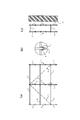
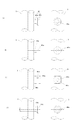
- Figure 1 shows an example of a wedge-tight scaffold.
- (a) is a front view of a wedge-binding scaffold
- (b) is an enlarged view of the periphery of the top indicated by a circle in (a)
- (c) is a right side view of the wedge-binding scaffold.
- Each support column 1 is formed by adding a support member 3 having a plurality of tops 4 on its side surface in the vertical direction via a tenon material (not shown).
- a connecting member 2 is connected in the horizontal direction one above the other via a frame 4 and is fastened with a wedge (not shown) to form a frame shape.
- the vertical plane is assembled.
- a brace member 21 is diagonally attached via a frame 4 between support members 3 facing on the opposite side of the building, and is fastened with a wedge (not shown) to form a frame shape.
- a frame consisting of the vertical plane and brace material is constructed.
- a handrail member 20 is further attached between the same support members 3 via the tops 4 and fastened with wedges. Thereafter, one or two floor cloth frames (not shown) are bridged between the connecting members 2 facing each other to form a first-stage scaffold.
- the second stage scaffolding is formed in the same manner as the first stage scaffolding, if necessary.
- a support member 3, a brace member 21, and a handrail member 20 are joined to a support member 3 prepared separately on the upper end of the support member 3 of the first stage in a vertical direction via a tenon material (not shown).
- the structural members are attached via the tops 4 and these scaffolding structural members are fastened together with wedges (not shown) at the tops 4, the floor-attached cloth frames (not shown) are respectively provided between the facing connecting members 2.
- two or more in parallel to form a second stage scaffold By repeating this sequentially, a multi-stage scaffold is assembled.
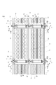
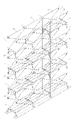
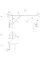
- FIG. 2 is a front view showing an example of the system support work
- FIG. 3 is a right side view of the system support work of FIG. 4 is a cross-sectional plan view taken along line AA in FIG.
- system supporter 100 is installed at a height of several m to several tens m from the ground so as to support the lower surface of the formwork 102 above the concrete structure (slab) 101.
- This system support work 100 is a framework constructed by arranging a plurality of support columns 1 in a matrix at predetermined intervals, and connecting adjacent support columns 1 in a horizontal two direction with a plurality of connecting members 2. Then, it is used as a scaffold by appropriately laying a cloth frame with a floor on it. That is, the horizontal first connecting member 2 is formed between the respective supporting columns 1 formed by adding the supporting members 3 having the plurality of tops 4 on the side surfaces in the vertical direction via the tenon material (not shown).
- a frame is formed by connecting a plurality of vertical surfaces in the horizontal direction with a second connecting member 2 installed in a direction orthogonal to the first connecting member 2 between the vertical surfaces assembled by connecting them with each other. Is built.
- each column 1 is supported by a jack base 5.
- a large jack jack 6 is attached to the upper end of each strut 1, and a plurality of large pull materials 7 are placed on the large jack jack 6.
- a plurality of joists 8 are placed on the plurality of large joists 7 and the formwork 102 is placed on the plurality of joists 8 so as to be orthogonal to the large joists 7.
- each support column 1 On the side surface of each support column 1, four frames 4 are formed in a cross shape at predetermined intervals (see FIG. 4).
- the connecting material 2 is connected to the frame 4 via a wedge metal piece joined to both ends of the connecting material 2 and is fastened by a wedge 2a.
- the connecting material 2 is not attached to the central piece 4 of each support member 3, but the connecting material 2 may be attached to the central piece 4 of each support member 3.
- the cloth frame 9 with a floor is bridged horizontally between the connecting material 2 which opposes.
- a scaffold for use as a work floor, a passage, a stage, or the like can be formed where necessary by laying the cloth frame 9 with a floor horizontally between the other facing connecting members 2.
- one scaffolding frame 9 is horizontally spanned between the opposing first tethers 2 to form one scaffold, which is used as a work floor, a passage or a stage.
- the column members provided with the connecting brackets such as frames are provided on the side surfaces, and the column members can be connected in the horizontal direction by the connecting material.
- the connecting material used here is made of steel or aluminum pipes with a wedge fitting joined to both ends of the pipe by welding or the like. By being fastened together, it can be used fixed to the column member.
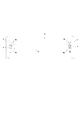
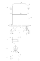
- FIG. 5 is a front view of an example of a connecting material (conventional example) used in a wedge-tight scaffold or system support.
- This connecting material 2 is formed by joining a wedge metal fitting 2b to both ends of a horizontal member 31 made of a pipe made of steel, aluminum or the like by welding or the like, and its total length is adjusted to the interval between the support members 3. .
- the hook member 2b of the connecting member 2 is hooked on a connecting metal member such as the top 4 provided on the side surface of the column member 3 and then fastened by the wedge 2a, whereby the column members 3 can be connected and fixed.
- FIG. 6 is a front view of an example (conventional example) of a binder with a wand disclosed in Patent Document 1.
- the connecting member 30 with a cane is a horizontal member for increasing the strength of the connecting member itself.
- Two wands 32 that support 31 from diagonally below are provided.
- the lower end portion of each cane 32 has a semi-cylindrical vertical plate 33 having an inner diameter substantially the same as the outer diameter of the column member 3, and the vertical plate 33 is pressed against the side surface of the column member 3. It has been.
- one bundle member 34 is installed vertically from the vicinity of the left and right ends of the horizontal member 31, and connects with the respective canes 32.
- each wand 32 is supported from above.
- the hook metal fittings 2b joined to both ends of the horizontal member 31 of the connecting material are hooked on connecting metal fittings such as the tops 4 provided on the side surfaces of the post member 3, respectively, and then fastened by the wedges 2a, whereby the post member 4 It is possible to connect and fix between.
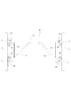
- FIG. 7 is a front view of an example (conventional example) of a connecting material with a cane disclosed in Patent Document 2.
- FIG. 7 is a front view of an example (conventional example) of a connecting material with a cane disclosed in Patent Document 2.
- the tie member 30 with the cane is joined to the two members that support the horizontal member 31 obliquely from below.
- a cane 32 is provided.
- the wedge metal fitting 30b is joined also to the lower end part of each cane 32 by welding etc.
- one bundle member 34 is installed vertically from the vicinity of the left and right ends of the horizontal member 31, and is connected to the respective canes 32. Thus, each wand 32 is supported from above.
- the strength of the tie material itself can be increased by providing a wand to the tie material in which the wedge metal fittings are joined by welding or the like at both ends of a horizontal member made of steel or aluminum.
- the tie material with a wand formed by joining a wedge metal fitting to the lower end of the wand has a great binding effect due to the wedge, the tie material can be firmly connected and fixed to the support column.
- 8 and 9 are examples of binding work by wedges when attaching the tie member with the wand shown in FIG. 7 between the support members.
- the present invention has been made to solve the above-described problems, and can facilitate and reduce the connection work with the support member, and can be firmly connected to the support member.
- An object is to provide a temporary scaffolding that incorporates a tether that can be used.
- the framework scaffolds use H-shaped or torii-shaped building frames in which the vertical columns and crosspieces are integrated, so they are heavy and bulky. Have.
- a wife's face is formed in front of or behind the work floor or passageway. Since it cannot be performed and a gap is generated, there is a problem in terms of safety of workers.
- the strut member and the connecting material are separate members and can be assembled on site. And since it is lightweight and does not become bulky, it is easy to carry. However, since the connecting portion of the support member and the connecting material is not integral, it is necessary to increase its strength.
- a connecting material that can be firmly connected to the support member a basic structure comprising a horizontal member made of a pipe made of steel or aluminum and two canes that support the horizontal member obliquely from below. It is desirable to adopt a structure that can be firmly connected to the left and right support members at a total of four locations, both ends of the horizontal member and the lower ends of the two canes.
- examples of the latching method between the end of the horizontal member and the support member include a combination of a button pin and a notch having a shape that can be latched on the button pin.
- the button pin is composed of a button part (large diameter) and a mounting shaft (small diameter)
- the width of the notch is smaller than the outer diameter of the button part and larger than the outer diameter of the mounting shaft, the end of the horizontal member The part can be hooked on the column member, and the end of the horizontal member is difficult to come off from the column member after hooking.
- a button pin will be provided in either the side surface of a support
- the wedge metal fitting for binding the wedge can be halved to only the two lower end portions of the left and right canes, and the height at the two left and right ends of the horizontal member can be reduced. This eliminates the need for a wedge work at the place. Therefore, it is possible to facilitate and reduce the binding work by the wedge.
- buttons having a shape that can be hooked to the button pin are employed as a hooking means between the end of the horizontal member and the column member, the button pin and the button pin are hooked.
- the combination of notches having a shape that can be formed is the following (i) or (ii).
- a button pin is provided on the side surface of the support member, and on the other hand, an end plate having a downward cutout is provided at the end of the horizontal member, and the end of the horizontal member is moved downward from above. Fit the downward notch on the button pin.
- the width of the downward notch provided on this end plate is larger than the outer diameter of the mounting shaft and smaller than the outer diameter of the button part. To do.
- an opening enough to accommodate the button portion is provided below the end plate or below the end portion of the horizontal member.
- the button pin can be joined to the side surface of the support member by welding or a screw.
- the horizontal member that is hooked on the side surface of the support member is not limited to one direction, and may be 2 to 4 directions on the circumference of the support member.
- the number of button pins to be installed is 1 to 4. When a plurality of button pins are joined to the circumference of the side surface of the support member by screws, it is preferable to use a blind nut.
- An upward notch is provided on the side of the support member, while a button pin is provided at the end of the horizontal member, and the button pin is moved upward by moving the end of the horizontal member downward from above. Fit into the notch.
- the width of the upward notch provided on the side surface of the support member is larger than the outer diameter of the button pin mounting shaft and smaller than the outer diameter of the button portion.
- the upward notch may be formed by attaching a thin frame on the side surface of the column and providing an upward notch on the front wall of the thin frame.
- the thin frame may have a shape with a missing bottom surface.
- the button pin can be joined to the end of the horizontal member by welding or a screw. Considering the labor of joining, it is preferable to join with screws such as blind nuts.
- the end of the horizontal member is moved downward from above, and the button pin provided on the end of the horizontal member is hooked on the upward notch provided on the side surface of the column member.
- the connection is not released unless the end of the horizontal member is moved upward.
- the horizontal member is a part of the connecting material with the cane
- the connection is not released unless the connecting material with the cane is moved upward. Since the end of the horizontal member is rotatable about the upward notch provided on the side surface of the column member as a rotation axis, it is not always necessary to move the end of the horizontal member from above. Even when moved from below, the end of the horizontal member can be hooked on the button pin.
- the wedge metal fittings provided at the lower ends of the left and right wands of the connecting material with the cane have a shape that can be included by sandwiching the connecting metal fittings such as the top and flange of the support member from above and below, for example, a C-shape when viewed from the front Is preferred.
- the wedge metal fitting has such a shape, once the connecting material with the cane is connected to the support member, even if the connecting material with the cane tries to move up and down, it will hit the connecting member of the support member, It can prevent that a binder with a cane comes off from a support
- a circular end plate having an outer diameter larger than the outer diameter of the horizontal member may be provided. Good. That is, an upward notch portion having a width smaller than the outer diameter of the circular end plate is provided on the side surface of the column member, and the circular end plate provided at the end portion of the horizontal member is moved downward from above. This button pin is fitted into the upward cutout.
- the end plate of the horizontal member is moved downward from above, and the circular end plate provided on the end of the horizontal member is hooked on the upward notch provided on the side surface of the column member. Accordingly, even when the circular end plate provided at the end of the horizontal member is connected to the support member, the connection is not released unless the end of the horizontal member is moved upward. In other words, since the horizontal member is a part of the connecting material with the cane, the connection is not released unless the connecting material with the cane is moved upward. Since the end of the horizontal member is rotatable about the upward notch provided on the side surface of the column member as a rotation axis, it is not always necessary to move the end of the horizontal member from above. Even when moved from below, the end of the horizontal member can be hooked on the button pin.
- the end portion of the horizontal member is rotatable about the button pin provided on the side surface of the support member or the upward notch as the rotation axis. That is, the tie material with the cane is rotatable about the button pin provided on the side surface of the support member or the upward notch as the rotation axis. Therefore, after the end of the horizontal member and the support member are connected, the wedge fitting provided at the lower end of the cane is fastened to the connection member of the support member with the wedge, and the wedge fitting and the support member at the lower end of the support member are connected. It is possible to easily align the connecting metal fittings.
- a handrail member is further placed between the strut members facing each other between the vertical surfaces.
- this handrail member can be attached to the handrail member via the connecting bracket between the strut members from the floor cloth frame after the floor-mounted cloth frame is laid.
- a leading handrail member that can be attached in advance. This is because when the leading handrail member is used, when the cloth frame with a floor is horizontally stretched and used for a work floor, a passage, a stage, or the like, the handrail members are already installed on both sides of the scaffold.
- the front handrail member can be rotated and fixed upward after the worker attaches the upper handrail member in advance from the lower scaffold when assembling the scaffold, and conversely the worker when disassembling the scaffold. Can be removed from the lower scaffold after rotating the upper handrail downward.
- a scaffold when forming a scaffold by laying a cloth frame with a floor, it is integrated with the handrail member as a brace material that connects the strut members facing each other between vertical surfaces to prevent the worker from falling. It is also possible to use a brace integrated handrail frame. Moreover, it is also possible to use a tie material with a handrail frame formed by joining the handrail member to a rotatable horizontal member of the tie material as a tie material for connecting the strut members facing each other between the vertical surfaces. At this time, the work efficiency of the assembly can be improved by adding the function of the handrail frame to the brace material.
- the brace member can be connected with a single brace-integrated handrail frame, and the work of attaching the brace material and the handrail material is performed once. You can do it.
- a wife surface is formed in front of or behind the work floor or aisle, but in the case of a wedge binding scaffold or system support, the frame is also continuous at the corners. As a result, the gap does not occur.
- a handrail member can be provided between the support members on the wife surface to prevent the worker from falling from the wife surface. In this case, the worker can attach the handrail member between the strut members on the wife's face from the floor-attached cloth frame after the floor-attached cloth frame is bridged. It is preferable to use a leading handrail member that can be attached to the front.
- the leading handrail member when the cloth frame with a floor is horizontally stretched and used as a work floor or a worker's passage, the handrail member is already installed on the scaffold surface.
- the connecting material it is more preferable to use a connecting material with a leading handrail frame-integrated type wand integrated by joining the preceding handrail frame.
- This tie material with a cane frame-integrated type cane can be rotated around the axis of the horizontal member that forms the tie material with a cane. After the member is attached in advance, it can be rotated and fixed upward. Conversely, when disassembling the scaffold, the operator can rotate the upper handrail downward and remove it from the lower scaffold.
- the present invention has been completed based on the above findings, and the gist of the present invention resides in the following temporary scaffolds (1) to (16).
- the present invention is collectively referred to as the present invention.
- a plurality of frame-shaped vertical surfaces which are assembled from support members having connecting metal fittings on the side surfaces and horizontal connecting members, are erected in parallel at appropriate intervals, and brace materials are provided between the support members facing each other between the vertical surfaces.
- a temporary scaffold constructed by constructing a frame consisting of a frame-shaped vertical surface and a brace material, and horizontally laying one or more floor-attached cloth frames between the facing tethers
- the connecting member in the vertical plane includes a horizontal member and two wands that support the horizontal member from obliquely below, and a hooking means for the column member is provided at both ends of the horizontal member.
- a temporary scaffold characterized in that the material is a tie material with a wand having a wedge metal fitting at the lower end of two wands.
- a column member having a connecting bracket on the side surface and a plurality of frame-shaped vertical surfaces assembled from the first horizontal connecting material in parallel at appropriate intervals, between the column members facing each other between the vertical surfaces Are connected by a second connecting member extending in the horizontal direction to construct a frame including the frame-shaped vertical surface and the first connecting member and the second connecting member, and the first connecting member facing between the vertical surfaces.
- a temporary scaffold formed by horizontally laying one or a plurality of floor-attached cloth frames in between, the first tether in the vertical plane supporting the horizontal member and the horizontal member from diagonally below 2
- Temporary scaffolding characterized by being a tether.
- the hooking means is an end plate that is provided on at least one of both ends of the horizontal member in the connecting member with the cane in the vertical plane and has a downward cutout.
- Temporary scaffolding in any one of 1) to (6).
- a button pin having a mounting shaft and a button portion having a diameter larger than that of the mounting shaft is provided on a side surface of the support member, and the width of the downward notch portion of the end plate is determined by the button portion of the button pin.
- the latch means is a button pin that is provided on at least one of both ends of the horizontal member in the connecting member with the cane in the vertical plane and has a mounting shaft and a button portion having a diameter larger than the mounting shaft.
- the temporary scaffold according to any one of (1) to (6) above.
- the button portion has an outer diameter larger than the width of the upward cutout portion provided on the side surface of the column member, and the mounting shaft has an outer diameter smaller than the width of the cutout portion.
- the hooking means is a circular end plate provided at at least one of both ends of the horizontal member in the connecting member with the cane in the vertical plane and having an outer diameter larger than the outer diameter of the horizontal member.
- the temporary scaffold according to any one of (1) to (6) above, (13) The temporary scaffold according to (12), wherein the end plate has an outer diameter larger than a width of an upward notch portion provided on a side surface of the column member.
- the tie material with a cane that is installed in the vertical plane used for the wife's face of the scaffold is a tie material with a leading handrail frame-integrated type cane that is integrated by joining the preceding handrail frame.
- the temporary scaffold according to any one of (1) to (15) above.
- a temporary scaffold in which a connecting material that can easily and reduce connection work with a support member and can be firmly connected to the support member is incorporated.
- FIG. 4 is a cross-sectional plan view taken along line AA in FIG. 3.
- FIG. 3 It is a front view of an example (conventional example) of a connecting material used in a wedge binding type scaffold or system support work.
- Patent Document 2 It is a front view of an example (conventional example) of a connecting material with a wand disclosed in Patent Document 2.
- (a) is a front view.
- (b) to (d) are enlarged views of part A, in which (b) is a left side view, (c) is a front view, and (d) is a bottom view.
- These are four examples of button pins provided on support members to be connected, all of which are joined to the side surfaces of the support members by welding. In each of the four examples (a) to (d), a front view is shown on the left side and a right side view is shown on the right side.
- FIG. 5D is a top view and FIG. 4D is a cross-sectional view (top view) of the joint portion in a state where the button pin is joined to the hole on the side surface of the support member.
- (a) is a top view
- (b) is a cross-sectional view (top view).
- (a) to (c) are front views
- (d) is an AA arrow view
- (e) is an BB arrow view.
- the state (front view) after connecting the connecting material with the cane of FIG. 10 to the side surface of the support member is shown.
- It is a temporary scaffold which concerns on 1st Embodiment, Comprising: It is a perspective view of the temporary scaffold which incorporates the connecting material with a cane of FIG.
- It is another example of a connecting material with a wand used in the temporary scaffolding according to the second embodiment.
- (a) is a front view.
- (b) to (d) are enlarged views of part A, in which (b) is a left side view, (c) is a front view, and (d) is a bottom view.
- FIG. 1 It is another example of a connecting material with a cane used in the temporary scaffolding according to the fourth embodiment.
- (a) is a front view
- (b) is an enlarged left side view of part A
- (c) is an enlarged front view of part A.
- a front view is shown on the left side
- a right side view is shown on the right side.
- (a) is the front view seen from the inside of a scaffold
- (b) is an enlarged view of the A section.
- (C) is a left side view of (b)
- (d) is a bottom view of (b).
- It is a temporary scaffold which concerns on 5th Embodiment, Comprising: The connecting material with a cane formed by joining the preceding handrail frame of FIG. 27 is incorporated in the wife's face of the scaffold.
- (a) is a plan view of the scaffold,
- (b) is a front view taken along the line AA of (a),
- (c) is a left side view taken along the line BB of (a), and
- (d) is (a) It is a CC arrow rear view of).
- FIG. 10 shows a connecting material with a cane used in the temporary scaffolding according to the first embodiment.
- (a) is a front view.
- (b) to (d) are enlarged views of part A, in which (b) is a left side view, (c) is a front view, and (d) is a bottom view.
- This tie member 30 with a cane is composed of a horizontal member 31 made of a pipe made of steel or aluminum, and two cane 32 that support the horizontal member 31 from obliquely below.
- An end plate 40 having a downward cutout 40a is joined to each end of the horizontal member 31 by welding or the like, and an opening 31a is provided below the end of the horizontal member 31.
- a wedge metal fitting 30b is joined to the lower end of the cane 32 by welding or the like. After the wedge metal fitting 30b is hooked on a connecting metal piece such as a frame provided on the side surface of the column member, the wedge 30a is attached.
- the wedge metal fitting 30b provided at the lower end of the wand 32 has a C shape when viewed from the front, the wedge metal fitting 30b sandwiches the connection metal fitting such as a frame provided on the side surface of the support member from above and below. Can be included. Therefore, once the connecting member 30 with the cane is connected to the support member, even if the connecting member 30 with the cane moves up and down, the connecting member 30 such as the top of the support member collides with the connecting member 30 such as the top member. Can be prevented from coming off from the support member.
- one bundle member 34 is installed vertically from the vicinity of the left and right ends of the horizontal member 31, and the respective canes 32 are connected to each other. The wand 32 is supported from above.
- the width of the downward cutout portion 40a provided on the end plate 40 joined to the end portion of the horizontal member 31 is smaller than the outer diameter of the button portion of the button pin provided on the column member to be connected. And larger than the outer diameter of the mounting shaft.
- the width of the opening 31a provided at the lower part of the end of the horizontal member 31 is larger than the outer diameter of the button portion of the button pin provided in the column member to be connected and the outer diameter of the mounting shaft. Greater than. Therefore, the end portion of the horizontal member 31 can be hooked to the column member, and the end portion of the horizontal member 31 is not easily detached from the column member after the latching.
- FIG. 11 shows four examples of button pins provided on support members to be connected.
- a front view is shown on the left side and a right side view is shown on the right side.
- Each button pin 41 includes a large-diameter button portion 41a and a small-diameter attachment shaft 41b.
- the attachment portion 41b is attached to the side surface of the column member 3 with the button portion 41a as an outer surface. Any joining means for attaching the button pin 41 to the side surface of the column member 3 is by welding.
- the outer diameter of the button portion 41 a is smaller than the width of the opening portion 31 a provided at the lower portion of the end portion of the horizontal member 31, and is provided on the end plate 40 joined to the end portion of the horizontal member 31. It is larger than the width of the downward cutout 40a.
- the outer diameter of the mounting portion 41 b is smaller than the width of the opening portion 31 a provided at the lower portion of the end portion of the horizontal member 31, and is provided on the end plate 40 joined to the end portion of the horizontal member 31. It is smaller than the width of the downward cutout 40a.
- FIG. 11A shows a truncated cone shape with an inclined portion on the back surface of the button portion 41a, and the mounting shaft 41b has a cylindrical shape.
- both the button portion 41a and the mounting shaft 41b are cylindrical.
- (c) is a modification of (b), and the attachment shaft 41b is attached to the side surface of the column member 3 via a columnar column fixing member 41c.
- (d) is a modification of (a). Since the attachment shaft 41b penetrates the column member 3 and can be attached by welding the attachment shaft 41b on the side opposite to the attachment side of the button pin, it can be firmly fixed.
- FIG. 12 shows another example of the button pin provided on the column member to be connected and an example of its joined state.
- (a) is a front view and right side view of the button pin
- (b) is a sectional view (front view) and right side view of the washer
- (c) is a state in which the button pin is joined to the hole on the side surface of the column member.
- FIG. 5D is a top view
- FIG. 4D is a cross-sectional view (top view) of the joint portion in a state where the button pin is joined to the hole on the side surface of the support member.
- the button pin 41 includes a button portion 41a having a truncated cone shape with an inclined portion on the back surface, a cylindrical mounting shaft 41b, and a navel having a male screw cut on the outer surface. It consists of a bolt 41d.
- the navel bolt 41d is screwed into a blind nut 51 previously inserted into a hole 52 formed in the side surface of the support member 3 through a navel washer 50 shown in FIG. As shown in FIGS. 12C and 12D, the button pin 41 is joined to the support member 3.
- the blind nut 51 After inserting the blind nut 51 having an internal thread cut into the hole 52 in a state of being inserted into a drive screw (not shown) at the tip of the tool, the blind nut 51 is inserted into the hole 52 by caulking. It fixes to 52.
- the button pin 41 can be joined to the column member 3 by screwing the navel bolt 41d into the fixed blind nut 51 via the navel washer 50. Therefore, labor can be saved compared to the joining work by welding.
- FIG. 13 shows a state in which the four button pins shown in FIG. 12 are joined on the circumference of the side surface of the column member to be connected.
- (a) is a top view
- (b) is a cross-sectional view (top view).
- the method of joining the button pin 41 to the support member 3 is as described above.
- the connecting members are connected in four directions, the number of button pins 41 to be installed on the circumference of the side surface of the column member 3 is four.
- the button pins are installed by screw joining using the blind nut 51, so that the other button pins do not get in the way during the installation operation.
- FIG. 14 shows a procedure for hooking the end portion of the horizontal member of the tie member with the cane of FIG. 10 on the button pin on the side surface of the column member of FIG. 11 (a).
- (a) to (c) are front views
- (d) is an AA arrow view
- (e) is an BB arrow view.
- (a) is the position where the end of the horizontal member 31 of the tie material with the cane is aligned with the support member 3 provided with the button pin 41 on the side surface, and (b) is the end of the horizontal member on the button pin 41.
- (C) shows the state where the button plate 41 is hooked with the downward notch 40a on the end plate 40 (both are front views). ).
- (D) is a sectional view taken along the line AA in (c), and (e) is a sectional view taken along the line BB in (d).
- a downward opening 31a is formed at the end of the horizontal member 31 of the connecting member with the cane, and the end plate 40 provided at the lower portion of the end of the horizontal member 31 has a downward notch.
- a portion 40a is formed. Then, by moving the end portion of the horizontal member 31 from above to below, the button plate 41 can be hooked with the downward notch portion 40 a of the end plate 40. Since the width of the notch 40a and the outer diameter of the button pin 41a and the mounting shaft 41b of the button pin are in the relationship as described above, the button plate 41 once has a notch 40a facing downward on the end plate 40. It can be seen that the connection of the end portion of the horizontal member 31 to the column member 3 is not released unless the end portion of the horizontal member 31 is lifted upward.
- the end plate 40 has play between the downward notch 40a and the button pin mounting shaft 41b. There is also play between the end plate 40 and the button part 41a of the button pin, so that the end part of the horizontal member rotates about the button pin mounting shaft 41b provided on the side surface of the support member. Be free.
- FIG. 15 shows the steps (a) to (d) for connecting and tightening the entire connecting member with the cane of FIG. 10 to the side surface of the column member (right side view).
- the end plate 40 of the horizontal member of the binder with the cane and the wedge metal fitting 30b joined to the lower end of the cane 32 are illustrated.
- (A) shows a column member 3 having a button pin 41 at the upper part of the side surface and a frame 4 at the lower part.
- (b) shows the middle of moving the end of the horizontal member from the upper side to the button pin 41 on the side surface of the column member 3, and
- (c) shows the state where the downward notch 40 a is hooked on the button pin 41.
- (D) shows that the wedge 30a is driven after the wedge metal fitting 30b joined to the lower end of the wand 32 is hooked on the top 4 on the side surface of the column member 3.
- FIG. 16 is an example of binding work by wedges when attaching the tie member with the wand shown in FIG. 10 between the support members.
- this tie member 30 with a cane no wedge metal fitting is provided at both ends of the horizontal member 31 present at a high place, and the wedge metal fitting 30b is provided at the lower end of the two canes that support the horizontal member 31 from obliquely below. They are only provided. Since the lower end of the cane exists in a low place where the worker can easily reach, the worker can easily perform the binding work of driving the wedge 30a with the hammer 36. In addition, since the wedge metal fitting 30b exists only in two places, the time for tightening work for driving the wedge 30a with the hammer 36 can be reduced.
- both ends of the horizontal member 31 are firmly attached to the column member 3 by the latching means, this cane is coupled with binding means by wedges at the lower ends of the two canes that support the horizontal member 31 from obliquely below. It can be seen that the connecting material 30 is firmly connected to the column member 3.
- FIG. 17 shows a state after the tie member 30 with the cane in FIG. 10 is connected to the side surface of the column member 3.
- FIG. 17 (a) is a front view
- FIG. 17 (b) is a CC view.
- the wedge 30 a for driving into the wedge metal fitting 30 b can be accommodated in a wedge temporary receiving hole 34 a provided in the middle of the bundle 34.
- FIG. 18 is an example (perspective view) of a temporary scaffold in which the tie member 30 with the cane of FIG. 10 is incorporated.
- a frame is constructed using the brace-integrated handrail frame 22 as a member for connecting the struts 1 facing each other between the vertical surfaces of the frame shape assembled from the struts 1 and the tie member 30 with the cane, And two cloth frames 9 with a floor are spanned horizontally between the connecting material 30 with a cane which opposes, respectively, and the scaffold is formed.
- the brace material integrated handrail frame 22 is provided on both sides of the scaffold, it can be installed only on the opposite side of the building.
- the temporary scaffolding incorporating the tie material with the cane is used as the tie material with the wand connected between the support members at the two places on both ends of the horizontal member even if the four parts are not fastened with wedges.
- the tie member with the cane can be firmly connected to the left and right support members by hooking to the support members instead of binding with wedges. Further, the operation of connecting the tie member with the cane between the support members is reduced and facilitated.
- the connecting material with a cane according to the conventional example has a cloth frame with a floor spanned on the connecting material as a support column due to the presence of the wedge metal fittings provided at both ends of the horizontal member.
- FIG. 19 shows a connecting material with a cane used in the temporary scaffolding according to the second embodiment.
- (a) is a front view.
- (b) to (d) are enlarged views of part A, in which (b) is a left side view, (c) is a front view, and (d) is a bottom view.
- FIG. 20 shows a state (front view) after the tie member 30 with the wand is connected to the side surface of the support member 3.
- This long tie material with a cane 30 differs from the tie material with a cane of the first embodiment only in that the horizontal member 31 is long. Therefore, similar to the tie material with the cane shown in the first embodiment, the tie material with the wand connected between the support members can be used at two places on both ends of the horizontal member even if all four places are not fastened with wedges. Can be firmly connected to the left and right column members by hooking to the column members instead of binding with wedges, so that a temporary scaffold similar to FIG. 18 can be constructed. . Further, the operation of connecting the tie member with the cane between the support members is reduced and facilitated. Further, the connecting material with a cane according to the conventional example (see FIGS.
- FIG. 21 is another example of a connecting material with a wand used in the temporary scaffolding according to the third embodiment.
- (A) of FIG. 21 is a front view
- (b) is an enlarged left side view of part A
- (c) is an enlarged front view of part A.
- This tie member 30 with a cane is composed of a horizontal member 31 made of a pipe made of steel or aluminum, and two cane 32 that support the horizontal member 31 from obliquely below.
- a button pin 41 is joined to each of the end portions of the horizontal member 31 via an end plate 40, and the end portion of the horizontal member 31 is secured by hooking the end portion of the horizontal member 31 to the support member. It can be connected to a strut member.
- a wedge metal fitting 30b is joined to the lower end of the cane 32 by welding or the like. After the wedge metal fitting 30b is hooked on a connecting metal piece such as a frame provided on the side surface of the column member, the wedge 30a is attached.
- the wedge metal fitting 30b provided at the lower end of the wand 32 has a C shape when viewed from the front, the wedge metal fitting 30b sandwiches the connection metal fitting such as a frame provided on the side surface of the support member from above and below. Can be included. Therefore, once the connecting member 30 with the cane is connected to the support member, even if the connecting member 30 with the cane moves up and down, the connecting member 30 such as the top of the support member collides with the connecting member 30 such as the top member. Can be prevented from coming off from the support member.
- one bundle member 34 is installed vertically from the vicinity of the left and right ends of the horizontal member 31, and the respective canes 32 are connected to each other. The wand 32 is supported from above.
- the button pin 41 includes a large-diameter button portion 41a and a small-diameter attachment shaft 41b, and is vertically attached to the end plate 40 joined to the end portion of the horizontal member 31.
- the outer diameter of the button part 41a is larger than the width
- the outer diameter of the mounting portion 41b is smaller than the width of the upward cutout portion. Therefore, the end portion of the horizontal member 31 can be hooked to the column member, and the end portion of the horizontal member 31 is not easily detached from the column member after the latching.
- the button pin attached to the end plate 40 joined to the end of the horizontal member 31 can be of the same shape as that shown in FIGS. Also, the button pin can be attached by welding or screwing in the same manner as in FIGS. Considering the labor of joining, it is preferable to join with screws such as blind nuts.
- FIG. 22 is an example of an upward cut-out portion provided in the support member to be connected.
- a front view is shown on the left side, and a right side view is shown on the right side.
- the upward notch 42a is formed by attaching a thin frame 42 to the side surface of the column member 3 and providing a notch on the front wall of the thin frame 42.
- FIG. 23 is a front view showing a procedure for hooking the end of the horizontal member of the tie member with the cane in FIG. 21 to the upward notch on the side surface of the column member in FIG.
- the button pin 41 is joined to the end portion of the horizontal member 31 of the tie material with the cane via the end plate 40. And the button pin 41 of the edge part of the horizontal member 31 is latched by the upward notch part 42a provided in the side surface of the support
- the button pins 41 at the ends of the horizontal members are hooked on the upward notches 42a on the side surfaces of the left and right support members 3, respectively.
- the tie member with the cane is rotated about the upward notch 42a as the rotation axis, and the lower ends of the left and right two canes 32 are aligned with the frames 4 on the side surfaces of the left and right support members 3, respectively.
- a procedure is adopted in which the wedge 30a is fastened by being driven into the wedge fitting 30b.
- the connecting member 30 with the cane can be connected to the side surface of the support member 3.
- the connecting material with a cane has a cloth frame with a floor spanned on the connecting material as a support column due to the presence of the wedge metal fittings provided at both ends of the horizontal member.
- FIG. 24 is another example of a connecting material with a cane used in the temporary scaffolding according to the fourth embodiment.
- (A) of FIG. 24 is a front view
- (b) is an enlarged left side view of part A
- (c) is an enlarged front view of part A.
- This tie member 30 with a cane is composed of a horizontal member 31 made of a pipe made of steel or aluminum, and two cane 32 that support the horizontal member 31 from obliquely below.
- An end plate 40 is joined to each end of the horizontal member 31, and the end of the horizontal member 31 is connected to the support member by hooking the end of the horizontal member 31 to the support member.
- a wedge metal fitting 30b is joined to the lower end of the cane 32 by welding or the like. After the wedge metal fitting 30b is hooked on a connecting metal piece such as a frame provided on the side surface of the column member, the wedge 30a is attached. By driving in, the lower end of the cane 32 can be fastened to the support member.
- the wedge metal fitting 30b provided at the lower end of the wand 32 has a C shape when viewed from the front, the wedge metal fitting 30b sandwiches the connection metal fitting such as a frame provided on the side surface of the support member from above and below. Can be included. Therefore, once the connecting member 30 with the cane is connected to the support member, even if the connecting member 30 with the cane moves up and down, the connecting member 30 such as the top of the support member collides with the connecting member 30 such as the top member. Can be prevented from coming off from the support member.
- one bundle member 34 is installed vertically from the vicinity of the left and right ends of the horizontal member 31, and the respective canes 32 are connected to each other. The wand 32 is supported from above.
- the outer diameter of the end plate 40 joined to the end portion of the horizontal member 31 is larger than the width of the upward notch provided on the front wall of the thin frame attached to the column member to be connected. large. Further, the outer diameter of the horizontal member 31 is smaller than the width of the upward notch. Therefore, the end portion of the horizontal member 31 can be hooked to the column member, and the end portion of the horizontal member 31 is not easily detached from the column member after the latching.
- FIG. 25 is an example of an upward cut-out portion provided in the support member to be connected.
- a front view is shown on the left side, and a right side view is shown on the right side.
- the upward notch 42a is formed by attaching a thin frame 42 to the side surface of the column member 3 and providing an upward notch on the front wall of the thin frame 42.
- FIG. 26 is a front view showing a procedure for hooking the end portion of the horizontal member of the tie member with the cane in FIG. 24 to the upward cut-out portion on the side surface of the column member in FIG.
- the end plate 40 is joined to the end portion of the horizontal member 31 of the binder with the cane. Then, by moving the end portion of the horizontal member 31 from above to below, the end plate 40 at the end portion of the horizontal member 31 is hooked on the upward notch portion 42a provided on the side surface of the support member 3. can do. Since the width of the notch 42a and the outer diameter of the end plate 40 and the horizontal member 31 are in the relationship as described above, once the end plate 40 is once hooked on the upward notch 42a. It can be seen that unless the end of the horizontal member 31 is lifted upward, the connection of the end of the horizontal member 31 to the column member 3 is not released.
- the work of connecting the tie member with the cane between the strut members is performed by first hooking the end plates 40 of the end portions of the horizontal members to the upward notches 42a on the side surfaces of the left and right strut members 3, respectively. After that, the tie member with the cane is rotated about the upward notch 42a as the rotation axis, and the lower ends of the left and right two canes 32 are aligned with the tops 4 on the side surfaces of the left and right support members 3, respectively. Then, a procedure is adopted in which the wedge 30a is fastened by being driven into the wedge fitting 30b.
- the connecting member 30 with the cane can be connected to the side surface of the support member 3.
- the connecting material with a cane has a cloth frame with a floor spanned on the connecting material as a support column due to the presence of the wedge metal fittings provided at both ends of the horizontal member.
- FIG. 27 shows a connecting material with a leading handrail frame integrated type cane used in the temporary scaffolding according to the fifth embodiment.
- (a) is the front view seen from the inside of a scaffold
- (b) is an enlarged view of the A section.
- (C) is a left side view of (b)
- (d) is a bottom view of (b).
- FIG. 28 shows an example of a temporary scaffold formed by incorporating the tie material with the leading handrail frame-integrated wand in FIG. 27 into the wife's face of the scaffold.
- (a) is a plan view
- (b) is a front view taken along arrow AA
- (c) is a left side view taken along arrow BB
- (d) is a rear view taken along arrow CC in FIG. .
- the leading handrail frame-integrated tie member with a wand 65 is composed of a leading handrail frame 61 and a tie member 30 with a wand formed by joining thereto.
- the connecting member 30 with a cane is composed of a horizontal member 31 made of a tube made of steel or aluminum, and two cane 32 supporting the horizontal member 31 from obliquely below, while the leading handrail frame 61 has an upper rail. 61a, left and right horizontal rails 61b, and middle rails 61c that connect the left and right horizontal rails 61b.
- the lower ends of the left and right horizontal rails 61b of the preceding handrail frame 61 are located on the side surfaces near the both ends of the horizontal member 31. Joined by welding or the like.
- the preceding handrail frame 61 can be rotated around the axis of the horizontal member 31, but in order to stop the rotation angle at 180 degrees, in the vicinity of the upper part of the left and right horizontal rails 61b of the preceding handrail frame 61, A pad 63 is attached to each.
- An end plate 40 having a downward cutout 40a is joined to each end of the horizontal member 31 by welding or the like, and an opening 31a is provided below the end of the horizontal member 31.
- the end of the horizontal member 31 can be connected to the support member by hooking the end of the horizontal member 31 to the support member.
- a wedge metal fitting 30b is joined to the lower end of the cane 32 by welding or the like. After hooking the wedge metal fitting 30b on a connecting metal fitting such as a frame provided on the side surface of the support member, the wedge 30a is attached. By driving in, the lower end of the cane 32 can be fastened to the support member.
- the wedge metal fitting 30b provided at the lower end of the wand 32 has a C shape when viewed from the front, the wedge metal fitting 30b sandwiches the connection metal fitting such as a frame provided on the side surface of the support member from above and below. Can be included.
- the tie member 30 with the wand formed by joining the leading handrail frame 61 may move up and down. Since it collides with a connecting bracket such as a frame of the support member, it is possible to prevent the connecting material 30 with the cane formed by joining the preceding handrail frame 61 from being detached from the support member.
- one bundle member 34 is installed vertically from the left and right end portions of the horizontal member 31, respectively. Each wand 32 is supported from above by tying each wand 32. Further, the wedge 30 a for driving into the wedge metal fitting 30 b can be accommodated in a wedge temporary receiving hole (not shown) provided in the middle of the bundle 34.
- the width of the downward cutout portion 40a provided on the end plate 40 joined to the end portion of the horizontal member 31 is smaller than the outer diameter of the button portion of the button pin provided on the column member to be connected. And larger than the outer diameter of the mounting shaft.
- the width of the opening 31a provided at the lower part of the end of the horizontal member 31 is larger than the outer diameter of the button portion of the button pin provided in the column member to be connected and the outer diameter of the mounting shaft. Greater than. Therefore, the end portion of the horizontal member 31 can be hooked to the column member, and the end portion of the horizontal member 31 is not easily detached from the column member after the latching.
- the horizontal member 31 can be rotated around the axis, when the end of the horizontal member 31 is hooked on the support member, the alignment becomes easy. And if it is such a latching structure, after the both ends of the horizontal member 31 are latched, the lower end part of a right and left cane is wedge-stripped, and it connects firmly between support
- the wedge metal fittings for tightening the wedge can be halved to only two places at the lower ends of the left and right canes, and the wedge work at the high places at the two left and right sides of the horizontal member 31 It becomes unnecessary. Therefore, it is possible to facilitate and reduce the binding work by the wedge.
- This tie material with a wand formed by joining the preceding handrail frame is a strut member on the wife's face to prevent the worker from falling from the wife's face formed on the scaffolding installed at the corner of the building. Can be installed between.
- This tie material with a cane that is formed by joining the preceding handrail frame can be attached in advance, so that when the cloth frame with a floor is stretched horizontally and used as a work floor or a worker's passage, the scaffold The handrail member can be in a state in which the handrail member is already installed.
- a temporary scaffold in which a connecting material that can facilitate and reduce the connection work with the support member and can be firmly connected to the support member is incorporated.
Landscapes
- Engineering & Computer Science (AREA)
- Architecture (AREA)
- Mechanical Engineering (AREA)
- Civil Engineering (AREA)
- Structural Engineering (AREA)
- Mutual Connection Of Rods And Tubes (AREA)
- Joining Of Building Structures In Genera (AREA)
Priority Applications (1)
| Application Number | Priority Date | Filing Date | Title |
|---|---|---|---|
| CN201280058611.0A CN103958801B (zh) | 2011-12-16 | 2012-10-30 | 临时脚手架 |
Applications Claiming Priority (2)
| Application Number | Priority Date | Filing Date | Title |
|---|---|---|---|
| JP2011-275952 | 2011-12-16 | ||
| JP2011275952A JP5809955B2 (ja) | 2011-12-16 | 2011-12-16 | 仮設足場 |
Publications (1)
| Publication Number | Publication Date |
|---|---|
| WO2013088848A1 true WO2013088848A1 (ja) | 2013-06-20 |
Family
ID=48612305
Family Applications (1)
| Application Number | Title | Priority Date | Filing Date |
|---|---|---|---|
| PCT/JP2012/078010 Ceased WO2013088848A1 (ja) | 2011-12-16 | 2012-10-30 | 仮設足場 |
Country Status (3)
| Country | Link |
|---|---|
| JP (1) | JP5809955B2 (https=) |
| CN (1) | CN103958801B (https=) |
| WO (1) | WO2013088848A1 (https=) |
Cited By (2)
| Publication number | Priority date | Publication date | Assignee | Title |
|---|---|---|---|---|
| DE102021122295A1 (de) | 2021-08-27 | 2023-03-02 | Peri Se | Gerüstriegel |
| WO2026011215A1 (en) * | 2024-07-12 | 2026-01-15 | Cobra Access Pty Ltd | Scaffold ledger |
Families Citing this family (2)
| Publication number | Priority date | Publication date | Assignee | Title |
|---|---|---|---|---|
| CN104533074B (zh) * | 2014-12-29 | 2016-09-14 | 天津大学 | 一种方便施加于支承架内外的通用节点斜撑 |
| JP6491895B2 (ja) * | 2015-01-30 | 2019-03-27 | エスアールジータカミヤ株式会社 | 仮設構造物の補強フレーム |
Citations (7)
| Publication number | Priority date | Publication date | Assignee | Title |
|---|---|---|---|---|
| JPS5397219A (en) * | 1977-02-03 | 1978-08-25 | Plettac Gmbh | Wedge connecting construction for building members |
| JPS59139607U (ja) * | 1983-03-09 | 1984-09-18 | 青木 育三 | 基材面における他部材の取付金具 |
| JPH0678492U (ja) * | 1993-04-12 | 1994-11-04 | アサヒ産業株式会社 | 仮設足場用ブレース手摺枠 |
| JP2003041766A (ja) * | 2001-05-21 | 2003-02-13 | Rarikku:Kk | 手摺り用仮設部材 |
| JP2009191506A (ja) * | 2008-02-14 | 2009-08-27 | Nippon Steel & Sumikin Metal Products Co Ltd | 手摺及び枠組足場 |
| JP2010019071A (ja) * | 2008-06-12 | 2010-01-28 | Shinwa Kk | 建築用足場の据置先行手摺 |
| JP2010138671A (ja) * | 2008-12-15 | 2010-06-24 | Krh Kk | 仮設足場用筋交い |
Family Cites Families (1)
| Publication number | Priority date | Publication date | Assignee | Title |
|---|---|---|---|---|
| CN201972388U (zh) * | 2011-01-20 | 2011-09-14 | 开平市优赢金属制品有限公司 | 一种桁架通道的脚手架 |
-
2011
- 2011-12-16 JP JP2011275952A patent/JP5809955B2/ja not_active Expired - Fee Related
-
2012
- 2012-10-30 WO PCT/JP2012/078010 patent/WO2013088848A1/ja not_active Ceased
- 2012-10-30 CN CN201280058611.0A patent/CN103958801B/zh not_active Expired - Fee Related
Patent Citations (7)
| Publication number | Priority date | Publication date | Assignee | Title |
|---|---|---|---|---|
| JPS5397219A (en) * | 1977-02-03 | 1978-08-25 | Plettac Gmbh | Wedge connecting construction for building members |
| JPS59139607U (ja) * | 1983-03-09 | 1984-09-18 | 青木 育三 | 基材面における他部材の取付金具 |
| JPH0678492U (ja) * | 1993-04-12 | 1994-11-04 | アサヒ産業株式会社 | 仮設足場用ブレース手摺枠 |
| JP2003041766A (ja) * | 2001-05-21 | 2003-02-13 | Rarikku:Kk | 手摺り用仮設部材 |
| JP2009191506A (ja) * | 2008-02-14 | 2009-08-27 | Nippon Steel & Sumikin Metal Products Co Ltd | 手摺及び枠組足場 |
| JP2010019071A (ja) * | 2008-06-12 | 2010-01-28 | Shinwa Kk | 建築用足場の据置先行手摺 |
| JP2010138671A (ja) * | 2008-12-15 | 2010-06-24 | Krh Kk | 仮設足場用筋交い |
Cited By (2)
| Publication number | Priority date | Publication date | Assignee | Title |
|---|---|---|---|---|
| DE102021122295A1 (de) | 2021-08-27 | 2023-03-02 | Peri Se | Gerüstriegel |
| WO2026011215A1 (en) * | 2024-07-12 | 2026-01-15 | Cobra Access Pty Ltd | Scaffold ledger |
Also Published As
| Publication number | Publication date |
|---|---|
| JP2013124541A (ja) | 2013-06-24 |
| JP5809955B2 (ja) | 2015-11-11 |
| CN103958801B (zh) | 2016-06-22 |
| CN103958801A (zh) | 2014-07-30 |
Similar Documents
| Publication | Publication Date | Title |
|---|---|---|
| US9861190B2 (en) | Wood gang form and method for constructing concrete building using same | |
| JP4567432B2 (ja) | 法面の作業床構築システムと作業床構築装置及び作業床パネル | |
| CN102561669B (zh) | 悬挑式脚手架及其施工方法 | |
| KR100809886B1 (ko) | 교각 코핑 폼 시스템 및 이를 이용하여 교각을 시공하는방법 | |
| JP5789606B2 (ja) | 方杖付つなぎ材および仮設足場 | |
| JP5809955B2 (ja) | 仮設足場 | |
| JP2002317552A (ja) | 仮設構造物の構築方法とこれに用いる手摺り筋交い | |
| KR20100123012A (ko) | 건축용 비계 | |
| JP2014009453A (ja) | 仮設足場組み立て冶具及び組み立て方法 | |
| JP2013124541A5 (https=) | ||
| JP5745898B2 (ja) | 先行手摺枠付き方杖型つなぎ材および仮設足場 | |
| JP7424694B1 (ja) | 仮設ステージ | |
| JP5971878B1 (ja) | 骨組構造物用構造材及びこれを用いた骨組構造物 | |
| JP2004316076A (ja) | 立体構築物 | |
| JP7190225B1 (ja) | 荷受けステージ | |
| US20040040786A1 (en) | Components for assembling scaffolding system | |
| JP6309327B2 (ja) | 木造建築物の水平架構の補強部材および木造建築物の水平架構の補強工法 | |
| JP2006241938A (ja) | 通し柱と梁との連結金具および木造建築物の軸組構造体 | |
| JP2024035126A (ja) | 足場ベース及び仮設足場の組立方法 | |
| US20150144427A1 (en) | Scaffold extension systems and methods | |
| JP2014031623A (ja) | 枠組足場用先行手摺及びその施工方法 | |
| KR200418150Y1 (ko) | 용이한 조립구조를 갖는 호이스트 방호울 | |
| JP2025151245A (ja) | 外壁部施工用足場構造 | |
| JP2707435B2 (ja) | 仮設建築物の組立屋根盤 | |
| JP5502396B2 (ja) | 手摺支柱および先行手摺 |
Legal Events
| Date | Code | Title | Description |
|---|---|---|---|
| WWE | Wipo information: entry into national phase |
Ref document number: 13149620 Country of ref document: CO |
|
| 121 | Ep: the epo has been informed by wipo that ep was designated in this application |
Ref document number: 12857297 Country of ref document: EP Kind code of ref document: A1 |
|
| NENP | Non-entry into the national phase |
Ref country code: DE |
|
| 122 | Ep: pct application non-entry in european phase |
Ref document number: 12857297 Country of ref document: EP Kind code of ref document: A1 |