WO2013086737A1 - 发光二极管的驱动电路与方法及其应用的显示装置 - Google Patents
发光二极管的驱动电路与方法及其应用的显示装置 Download PDFInfo
- Publication number
- WO2013086737A1 WO2013086737A1 PCT/CN2011/084125 CN2011084125W WO2013086737A1 WO 2013086737 A1 WO2013086737 A1 WO 2013086737A1 CN 2011084125 W CN2011084125 W CN 2011084125W WO 2013086737 A1 WO2013086737 A1 WO 2013086737A1
- Authority
- WO
- WIPO (PCT)
- Prior art keywords
- signal
- power switch
- high frequency
- dimming
- dimming signal
- Prior art date
- Legal status (The legal status is an assumption and is not a legal conclusion. Google has not performed a legal analysis and makes no representation as to the accuracy of the status listed.)
- Ceased
Links
Images

Classifications
-
- G—PHYSICS
- G09—EDUCATION; CRYPTOGRAPHY; DISPLAY; ADVERTISING; SEALS
- G09G—ARRANGEMENTS OR CIRCUITS FOR CONTROL OF INDICATING DEVICES USING STATIC MEANS TO PRESENT VARIABLE INFORMATION
- G09G3/00—Control arrangements or circuits, of interest only in connection with visual indicators other than cathode-ray tubes
- G09G3/20—Control arrangements or circuits, of interest only in connection with visual indicators other than cathode-ray tubes for presentation of an assembly of a number of characters, e.g. a page, by composing the assembly by combination of individual elements arranged in a matrix no fixed position being assigned to or needed to be assigned to the individual characters or partial characters
- G09G3/34—Control arrangements or circuits, of interest only in connection with visual indicators other than cathode-ray tubes for presentation of an assembly of a number of characters, e.g. a page, by composing the assembly by combination of individual elements arranged in a matrix no fixed position being assigned to or needed to be assigned to the individual characters or partial characters by control of light from an independent source
- G09G3/3406—Control of illumination source
-
- G—PHYSICS
- G09—EDUCATION; CRYPTOGRAPHY; DISPLAY; ADVERTISING; SEALS
- G09G—ARRANGEMENTS OR CIRCUITS FOR CONTROL OF INDICATING DEVICES USING STATIC MEANS TO PRESENT VARIABLE INFORMATION
- G09G3/00—Control arrangements or circuits, of interest only in connection with visual indicators other than cathode-ray tubes
- G09G3/20—Control arrangements or circuits, of interest only in connection with visual indicators other than cathode-ray tubes for presentation of an assembly of a number of characters, e.g. a page, by composing the assembly by combination of individual elements arranged in a matrix no fixed position being assigned to or needed to be assigned to the individual characters or partial characters
- G09G3/34—Control arrangements or circuits, of interest only in connection with visual indicators other than cathode-ray tubes for presentation of an assembly of a number of characters, e.g. a page, by composing the assembly by combination of individual elements arranged in a matrix no fixed position being assigned to or needed to be assigned to the individual characters or partial characters by control of light from an independent source
- G09G3/36—Control arrangements or circuits, of interest only in connection with visual indicators other than cathode-ray tubes for presentation of an assembly of a number of characters, e.g. a page, by composing the assembly by combination of individual elements arranged in a matrix no fixed position being assigned to or needed to be assigned to the individual characters or partial characters by control of light from an independent source using liquid crystals
- G09G3/3611—Control of matrices with row and column drivers
- G09G3/3648—Control of matrices with row and column drivers using an active matrix
-
- H—ELECTRICITY
- H05—ELECTRIC TECHNIQUES NOT OTHERWISE PROVIDED FOR
- H05B—ELECTRIC HEATING; ELECTRIC LIGHT SOURCES NOT OTHERWISE PROVIDED FOR; CIRCUIT ARRANGEMENTS FOR ELECTRIC LIGHT SOURCES, IN GENERAL
- H05B45/00—Circuit arrangements for operating light-emitting diodes [LED]
- H05B45/30—Driver circuits
- H05B45/32—Pulse-control circuits
- H05B45/325—Pulse-width modulation [PWM]
-
- G—PHYSICS
- G09—EDUCATION; CRYPTOGRAPHY; DISPLAY; ADVERTISING; SEALS
- G09G—ARRANGEMENTS OR CIRCUITS FOR CONTROL OF INDICATING DEVICES USING STATIC MEANS TO PRESENT VARIABLE INFORMATION
- G09G2320/00—Control of display operating conditions
- G09G2320/06—Adjustment of display parameters
- G09G2320/0613—The adjustment depending on the type of the information to be displayed
- G09G2320/062—Adjustment of illumination source parameters
-
- G—PHYSICS
- G09—EDUCATION; CRYPTOGRAPHY; DISPLAY; ADVERTISING; SEALS
- G09G—ARRANGEMENTS OR CIRCUITS FOR CONTROL OF INDICATING DEVICES USING STATIC MEANS TO PRESENT VARIABLE INFORMATION
- G09G2320/00—Control of display operating conditions
- G09G2320/06—Adjustment of display parameters
- G09G2320/0626—Adjustment of display parameters for control of overall brightness
-
- Y—GENERAL TAGGING OF NEW TECHNOLOGICAL DEVELOPMENTS; GENERAL TAGGING OF CROSS-SECTIONAL TECHNOLOGIES SPANNING OVER SEVERAL SECTIONS OF THE IPC; TECHNICAL SUBJECTS COVERED BY FORMER USPC CROSS-REFERENCE ART COLLECTIONS [XRACs] AND DIGESTS
- Y02—TECHNOLOGIES OR APPLICATIONS FOR MITIGATION OR ADAPTATION AGAINST CLIMATE CHANGE
- Y02B—CLIMATE CHANGE MITIGATION TECHNOLOGIES RELATED TO BUILDINGS, e.g. HOUSING, HOUSE APPLIANCES OR RELATED END-USER APPLICATIONS
- Y02B20/00—Energy efficient lighting technologies, e.g. halogen lamps or gas discharge lamps
- Y02B20/30—Semiconductor lamps, e.g. solid state lamps [SSL] light emitting diodes [LED] or organic LED [OLED]
Definitions
- the present invention relates to a driving circuit and method for a light emitting diode, and more particularly to a driving circuit and method for a light emitting diode applicable to a backlight module and a display device.
- Liquid crystal display (Liquid Crystal Display, LCD) has been widely used in a variety of electronic products, most of the liquid crystal display is a backlight type liquid crystal display, which is composed of a liquid crystal display panel and a backlight module (backlight Module).
- the backlight module can be divided into a side-light type and a direct-light type according to the incident position of the light source (Direct-light) Type) Two to provide a backlight to the LCD panel.
- Direct-light Direct-light
- LED Due to light-emitting diodes (Light-Emitting) Diode, LED) has good optoelectronic properties such as low power consumption, low heat generation, long operating life, impact resistance, small volume, fast response, and color light that emits stable wavelengths, so it is suitable for use in backlight modules.
- pulse width modulation In the driving circuit of the LED, pulse width modulation is usually used.
- Modulation, PWM A dimming signal that controls the switching of the LED current to control the brightness of the LED.
- the dimming signal is a low frequency PWM signal
- the brightness of the LED cannot be changed frequently during a specific dimming period for a short period of time, thus affecting the dimming effect of the LED.
- the invention provides a driving circuit and method for a light emitting diode and a display device thereof, to solve the dimming problem of a low frequency PWM signal.
- a main object of the present invention is to provide a driving circuit for driving a plurality of light emitting diodes, the driving circuit comprising:
- the dimming circuit includes a multiplier for multiplying a pulse width modulated dimming signal with a high frequency dimming signal to provide a driving signal to the In the power switch, the high frequency dimming signal is converted by a picture signal of the display panel.
- the power switch is an N-channel MOS transistor.
- a drain of the power switch is connected to the light emitting diode, a source of the power switch is connected to the resistor, and a gate of the power switch is connected to the Dimming circuit.
- the high frequency dimming signal is provided by a timing controller.
- the high frequency dimming signal is a high frequency pulse width modulated signal.
- Still another object of the present invention is to provide a driving method for driving a plurality of light emitting diodes, wherein the light emitting diodes are connected to a power switch, and the driving method includes:
- the pulse width modulated dimming signal is multiplied with the high frequency dimming signal to provide a drive signal to the power switch.
- the high frequency dimming signal is provided by a timing controller.
- the high frequency dimming signal is a high frequency pulse width modulated signal.
- the pulse width modulation dimming signal and the high frequency dimming signal are multiplied by a multiplier of the dimming circuit.
- the backlight module includes:
- the dimming circuit includes a multiplier for multiplying a pulse width modulated dimming signal with a high frequency dimming signal provided by the timing controller And providing a driving signal to the power switch, wherein the high frequency dimming signal is converted by a picture signal of the display panel.
- the driving circuit and method of the light emitting diode of the present invention can further dim the light emitting diode in a specific dimming period for a short time to improve the dimming effect of the light emitting diode and the contrast of the display panel, thereby improving the display of the display device. quality.
- FIG. 1 is a cross-sectional view showing a backlight module and a display panel in accordance with a first embodiment of the present invention
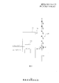
- Figure 2 is a circuit diagram showing a driving circuit in accordance with a first embodiment of the present invention
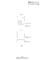
- FIG. 3 is a waveform diagram showing a PWM dimming signal and a high frequency dimming signal in accordance with the present invention.
- the driving circuit 150 of this embodiment can be used to drive a plurality of light emitting diodes (Light-Emitting) Diode, LED) 120, these LEDs 120 can be connected in series to form a string of LEDs to serve as a light source for the backlight module 100.
- the backlight module 100 can be a lateral light input or a direct light input light, which is disposed relative to a display panel 101 (for example, a liquid crystal display panel) to form a display device (for example, a liquid crystal display device).
- the display device of this embodiment includes a timing controller (Timing The controller (Tcon) 102 is configured to provide a picture signal to the display panel 101 and provide a corresponding backlight driving signal to the backlight module 100.
- the backlight module 100 can be, for example, a direct type backlight module, including a back plate 110 , a plurality of light emitting diodes (LEDs) 120 , a circuit board 130 , a reflective layer 140 , a driving circuit 150 , and Optical film 160.
- the backplane 110 is configured to carry the LED 120 and the circuit board 130.
- the LED 120 can be disposed on the circuit board 130 and electrically connected to the driving circuit 150 through the circuit board 130 for emitting light to the display panel 101.
- Circuit board 130 can be a printed circuit board (Printed Circuit board, PCB) or flexible printed circuit board (Flexible Printed Circuits, FPC).
- the reflective layer 140 is formed around the light emitting diode 120 (for example, formed on the circuit board 130 or the back plate 110) to reflect the light of the LED 120.
- the driving circuit 150 can be electrically connected to the light emitting diode 120 through the circuit board 130.
- the optical film 160 is disposed above the light emitting diode 120 to improve the uniformity of illumination or the luminous efficiency of the light emitting diode 120.
- the driving circuit 150 of this embodiment includes a power switch Q1, resistor R1 and dimming circuit 151.
- the power switch Q1 is connected between the light emitting diode 120 and the resistor R1. Resistor R1 is electrically grounded.
- the dimming circuit 151 is connected to the power switch Q1 for transmitting a driving signal to the power switch Q1 to adjust the brightness of the LED 120. Wherein, the dimming circuit 151 can be integrated into an IC chip.
- the power switch Q1 is, for example, an enhancement type N-channel metal oxide semiconductor (NMOS) transistor, the drain of which is connected to the light emitting diode 120; the source thereof is connected to the resistor R1; and the gate thereof is connected to Dimming circuit 151.
- NMOS metal oxide semiconductor
- the dimming circuit 151 of the present embodiment is connected between the timing controller 102 and the power switch Q1, the dimming circuit 151 includes a multiplier 152, and the multiplier 152 is connected to the power switch Q1 and can receive A pulse width modulation (PWM) dimming signal and a high frequency dimming signal.
- PWM dimming signal can be provided by an external system terminal (not shown) and transmitted to the dimming circuit 151 via the timing controller 102.
- this PWM dimming signal is a low frequency PWM signal.
- This high frequency dimming signal is provided by the timing controller 102, and this high frequency dimming signal is a high frequency PWM signal converted from a picture signal supplied to the display panel 101.
- the frequency of the high frequency dimming signal converted into the picture signal is higher than the external PWM dimming signal.
- the frequency of the high frequency dimming signal is twice or more than the PWM dimming signal.
- the multiplier 152 of the dimming circuit 151 can multiply the PWM dimming signal and the high frequency dimming signal transmitted by the timing controller 102 to form a multiplied driving signal, so that the dimming circuit 151 can provide the phase.
- the multiplied drive signal is used as the drive waveform of the power switch Q1.
- the driving method of the embodiment may include the steps of: providing a PWM dimming signal; providing the high frequency dimming signal, wherein the high frequency dimming signal is provided by the display panel 101 The picture signal is converted; and the PWM dimming signal is multiplied with the high frequency dimming signal to provide a driving signal to the power switch Q1 of the driving circuit 150.
- the system terminal When adjusting the brightness of the LED 120, the system terminal (not shown) can transmit a PWM dimming signal to the timing controller 102, and the PWM dimming signal can be supplied to the driving circuit 150 through the timing controller 102.
- the timing controller 102 may convert the picture signal of the display panel 101 into the high frequency dimming signal (high frequency PWM signal) corresponding to different pictures (such as a dark picture or a bright picture) of the display panel 101, and provide
- the dimming circuit 151 to the driving circuit 150 causes the multiplier 152 of the dimming circuit 151 to multiply the PWM dimming signal and the high frequency dimming signal transmitted by the timing controller 102, thereby providing an externally provided low frequency PWM modulation
- a high frequency PWM dimming signal is superimposed in the optical signal, and the driving waveform superimposed with the high frequency PWM signal is supplied to the power switch Q1 of the driving circuit 150 to perform switching control on the power switch Q1, and the adjustable light is adjusted.
- FIG. 3 shows waveform diagrams of a PWM dimming signal and a high frequency dimming signal in accordance with the present invention.
- the low frequency PWM dimming signal can only be used in a short dimming period T.
- the power switch Q1 since the multiplier 152 of the dimming circuit 151 can superimpose the high frequency dimming signal in the PWM dimming signal to provide the driving signal, in this dimming period T, the dimming circuit 151 of the driving circuit 150 can The brightness of the light emitting diode 120 is further adjusted.
- the light emitting diode 120 can be further dimmed in a specific dimming period for a short time to improve the dimming effect of the light emitting diode 120, and Helps to increase the contrast of the display panel 101, thereby improving the display quality of the display device.
- the driving circuit can also be applied to a backlight module that is laterally lighted.
- the backlight module may include a back plate, a plurality of light emitting diodes, a circuit board, a reflective layer, a driving circuit, an optical film, and a light guide plate.
- the light guide plate is disposed on the back plate, and the light emitting diode can be disposed on the circuit board to form a light bar, which can be disposed on one side of the light guide plate for laterally emitting light into the light guide plate, and guided by The light board guides the light out.
- the driving circuit can be electrically connected to the light emitting diode through the circuit board to drive the light emitting diode.
- the driving circuit and method of the light emitting diode of the present invention can multiply the PWM dimming signal and the high frequency dimming signal compared to the conventional method of dimming using the low frequency PWM signal. Therefore, in a specific dimming period of a short time, the driving circuit and the method of the LED of the present invention can further dim the LED to improve the dimming effect of the LED and the contrast of the display panel. The display quality of the display device can be improved.
Landscapes
- Engineering & Computer Science (AREA)
- Physics & Mathematics (AREA)
- Computer Hardware Design (AREA)
- General Physics & Mathematics (AREA)
- Theoretical Computer Science (AREA)
- Chemical & Material Sciences (AREA)
- Crystallography & Structural Chemistry (AREA)
- Control Of Indicators Other Than Cathode Ray Tubes (AREA)
- Liquid Crystal Display Device Control (AREA)
Abstract
本发明提供一种发光二极管的驱动电路与方法及其应用的显示装置。此驱动电路包括功率开关及调光电路。此方法包括提供脉冲宽度调制调光信号及高频调光信号;以及将所述脉冲宽度调制调光信号与所述高频调光信号进行相乘,以提供一驱动信号至所述功率开关。本发明可改善发光二极管的调光效果。
Description
本发明涉及一种发光二极管的驱动电路与方法,特别是涉及一种可应用于背光模块与显示装置的发光二极管的驱动电路与方法。
液晶显示器(Liquid Crystal
Display,LCD)已被广泛应用于各种电子产品中,液晶显示器大部分为背光型液晶显示器,其是由液晶显示面板及背光模块(backlight
module)所组成。背光模块可依照光源入射位置的不同分成侧向式入光(Side-light type)与直下式入光(Direct-light
type)两种,藉以提供背光源至液晶显示面板。
由于发光二极管(Light-Emitting
Diode,LED)具有低耗电量、低发热量、操作寿命长、耐撞击、体积小、反应速度快、以及可发出稳定波长的色光等良好光电特性,因而适合应用于背光模块的光源。
在LED的驱动电路中,通常使用脉冲宽度调制(pulse width
modulation,PWM)调光信号来控制LED电流的开关,以控制LED的亮度。
然而,当调光信号为低频的PWM信号,因此,在一短时间的特定调光期间中,LED的亮度无法频繁地进行改变,因而影响LED的调光效果。
故,有必要提供一种发光二极管的驱动电路与方法及其应用的显示装置,以解决现有技术所存在的问题。
本发明提供一种发光二极管的驱动电路与方法及其应用的显示装置,以解决低频的PWM信号的调光问题。
本发明的主要目的在于提供一种驱动电路,用于驱动多个发光二极管,所述驱动电路包括:
功率开关,连接于所述发光二极管;
电阻,连接于所述功率开关,并电性接地;
调光电路,连接于所述功率开关,其中所述调光电路包括一乘法器,用于将一脉冲宽度调制调光信号与一高频调光信号进行相乘,以提供一驱动信号至所述功率开关,所述高频调光信号是由显示面板的一画面信号所转换而成。
在本发明的一实施例中,所述功率开关为N沟道金属氧化物半导体晶体管。
在本发明的一实施例中,所述功率开关的漏极是连接于所述发光二极管,所述功率开关的源极是连接于所述电阻,所述功率开关的栅极是连接于所述调光电路。
在本发明的一实施例中,所述高频调光信号是由时序控制器所提供。
在本发明的一实施例中,所述高频调光信号是高频脉冲宽度调制信号。
本发明的又一目的在于提供一种驱动方法,用于驱动多个发光二极管,其中所述发光二极管是连接于一功率开关,所述驱动方法包括:
提供一脉冲宽度调制调光信号;
提供一高频调光信号,其中所述高频调光信号是由显示面板的一画面信号所转换而成;以及
将所述脉冲宽度调制调光信号与所述高频调光信号进行相乘,以提供一驱动信号至所述功率开关。
在本发明的一实施例中,所述高频调光信号是由时序控制器所提供。
在本发明的一实施例中,所述高频调光信号是高频脉冲宽度调制信号。
在本发明的一实施例中,所述所述脉冲宽度调制调光信号与所述高频调光信号是通过调光电路的乘法器来进行相乘。
本发明的又一目的在于提供一种显示装置,所述显示装置包括:
显示面板;
时序控制器;以及
背光模块,包括:
背板;
多个发光二极管,设置于所述背板上;以及
驱动电路,电性连接于所述发光二极管,用于驱动所述多个发光二极管,其中所述驱动电路包括:
功率开关,连接于所述发光二极管;
电阻,连接于所述功率开关,并电性接地;
调光电路,连接于所述功率开关,其中所述调光电路包括一乘法器,用于将一脉冲宽度调制调光信号与所述时序控制器所提供的一高频调光信号进行相乘,以提供一驱动信号至所述功率开关,所述高频调光信号是由显示面板的一画面信号所转换而成。
本发明的发光二极管的驱动电路与方法可在短时间的特定调光期间中进一步地对发光二极管进行调光,以改善发光二极管的调光效果以及显示面板的对比度,进而可改善显示装置的显示质量。
图1显示依照本发明的第一实施例的背光模块与显示面板的剖面示意图;
图2显示依照本发明的第一实施例的驱动电路的电路图;
[根据细则91更正 08.03.2012]
图3显示依照本发明的PWM调光信号及高频调光信号的波形图。
图3显示依照本发明的PWM调光信号及高频调光信号的波形图。
[根据细则91更正 08.03.2012]
以下各实施例的说明是参考附加的图式,用以例示本发明可用以实施的特定实施例。本发明所提到的方向用语,例如「上」、「下」、「前」、「后」、「左」、「右」、「内」、「外」、「侧面」等,仅是参考附加图式的方向。因此,使用的方向用语是用以说明及理解本发明,而非用以限制本发明。
在图中,结构相似的单元是以相同标号表示。
请参照图1,其显示依照本发明的第一实施例的背光模块与显示面板的剖面示意图。本实施例的驱动电路150可用以驱动多个发光二极管(Light-Emitting
Diode,LED)120,这些发光二极管120可串联成一发光二极管串,以作为背光模块100的光源。此背光模块100可为侧向式入光或直下式入光,其相对于一显示面板101(例如液晶显示面板)来设置,而形成一显示装置(例如液晶显示装置)。本实施例的显示装置包括一时序控制器(Timing
Controller,Tcon)102,用于提供画面信号至显示面板101,且提供对应的背光驱动信号至背光模块100。
如图1所示,在本实施例中,背光模块100可例如为直下式背光模块,其包括背板110、多个发光二极管(LED)120、电路板130、反射层140、驱动电路150及光学膜片160。背板110用以承载发光二极管120及电路板130,发光二极管120可设置于电路板130上,并通过电路板130来电性连接于驱动电路150,用以发光来提供光线至显示面板101。电路板130可为印刷电路板(Printed
circuit board,PCB)或柔性印刷电路板(Flexible Printed
Circuits,FPC)。反射层140是形成于发光二极管120的周围(例如形成于电路板130或背板110上),用以反射发光二极管120的光线。驱动电路150可通过电路板130来电性连接于发光二极管120。光学膜片160是设置于发光二极管120上方,用以改善发光二极管120的发光均匀性或发光效率。
请参照图2,其显示依照本发明的第一实施例的驱动电路的电路图。本实施例的驱动电路150包括功率开关
Q1、电阻R1及调光电路151。功率开关Q1是连接于发光二极管120与电阻R1之间。电阻R1是电性接地。调光电路151是连接于所述功率开关Q1,用于传送一驱动信号至功率开关Q1,以调整发光二极管120的亮度。其中,调光电路151可整合成一IC芯片
在本实施例中,功率开关Q1例如为增强型N沟道金属氧化物半导体(NMOS)晶体管,其漏极是连接于发光二极管120;其源极是连接于电阻R1;其栅极是连接于调光电路151。
如图2所示,本实施例的调光电路151是连接于时序控制器102与功率开关Q1之间,调光电路151包括乘法器152,乘法器152是连接于功率开关Q1,并可接收一脉冲宽度调制(PWM)调光信号与一高频调光信号。此PWM调光信号可由外部的系统端(未显示)所提供,并通过时序控制器102来传送至调光电路151。一般地,此PWM调光信号为低频的PWM信号。此高频调光信号是由时序控制器102所提供,且此高频调光信号是由所提供至显示面板101的画面信号来转换成的高频PWM信号。画面信号来转换成的高频调光信号的频率是高于外部传来的PWM调光信号。例如,高频调光信号的频率是PWM调光信号的2倍或3倍以上。调光电路151的乘法器152可将时序控制器102所传送的PWM调光信号及高频调光信号进行相乘,以形成一相乘后的驱动信号,使得调光电路151可提供此相乘后的驱动信号来作为所述功率开关Q1的驱动波形。
当利用驱动电路150来驱动发光二极管120时,本实施例的驱动方法可包括如下步骤:提供PWM调光信号;提供此高频调光信号,其中所述高频调光信号是由显示面板101的画面信号所转换而成;以及将PWM调光信号与此高频调光信号进行相乘,以提供驱动信号至驱动电路150的所述功率开关Q1。
当调整发光二极管120的亮度时,系统端(未显示)可传送一PWM调光信号至时序控制器102,通过时序控制器102,PWM调光信号可被提供至驱动电路150。同时,时序控制器102可对应于显示面板101的不同画面(如暗画面或亮画面),而将显示面板101的画面信号转换成此高频调光信号(高频的PWM信号),并提供至驱动电路150的调光电路151,使得调光电路151的乘法器152将时序控制器102所传送的PWM调光信号及高频调光信号进行相乘,因而可在外部提供的低频PWM调光信号中迭加高频的PWM调光信号,并提供此迭加有高频PWM信号的驱动波形至驱动电路150的所述功率开关Q1,以对功率开关Q1进行开关控制,而可调整发光二极管120的亮度。
请参照图3,其显示依照本发明的PWM调光信号及高频调光信号的波形图。相较于亮画面的PWM调光信号及高频调光信号,当显示面板101显示暗画面或亮度较低的画面时,在一短暂的调光期间T中,低频PWM调光信号仅能用于开启功率开关Q1。此时,由于调光电路151的乘法器152可迭加高频调光信号于PWM调光信号中来提供驱动信号,因此,在此调光期间T中,驱动电路150的调光电路151可进一步调整发光二极管120的亮度。
因此,通过本实施例的发光二极管的驱动电路与方法,在一短时间的特定调光期间中,可进一步地对发光二极管120进行调光,以改善发光二极管120的调光效果,并可有助于提高显示面板101的对比度,因而可改善显示装置的显示质量。
[根据细则91更正 08.03.2012]
在本实施例中,驱动电路亦可应用于侧向式入光的背光模块。此时,背光模块可包括背板、多个发光二极管、电路板、反射层、驱动电路、光学膜片及导光板。导光板是设置于背板上,发光二极管可设置于电路板上,而形成发光灯条(lightbar),其可设置于导光板的一侧,用以侧向发光至导光板内,并由导光板来导引出光。驱动电路可通过电路板来电性连接于发光二极管,用以驱动发光二极管。
在本实施例中,驱动电路亦可应用于侧向式入光的背光模块。此时,背光模块可包括背板、多个发光二极管、电路板、反射层、驱动电路、光学膜片及导光板。导光板是设置于背板上,发光二极管可设置于电路板上,而形成发光灯条(lightbar),其可设置于导光板的一侧,用以侧向发光至导光板内,并由导光板来导引出光。驱动电路可通过电路板来电性连接于发光二极管,用以驱动发光二极管。
由上述可知,相较于现有的利用低频PWM信号来调光的方法,本发明的发光二极管的驱动电路与方法可将PWM调光信号与此高频调光信号进行相乘。因此,在一短时间的特定调光期间中,通过本发明的发光二极管的驱动电路与方法,可进一步地对发光二极管进行调光,以改善发光二极管的调光效果以及显示面板的对比度,进而可改善显示装置的显示质量。
综上所述,虽然本发明已以优选实施例揭露如上,但上述优选实施例并非用以限制本发明,本领域的普通技术人员,在不脱离本发明的精神和范围内,均可作各种更动与润饰,因此本发明的保护范围以权利要求界定的范围为准。
Claims (13)
- 一种驱动电路,用于驱动多个发光二极管,其中所述驱动电路包括:功率开关,连接于所述发光二极管;电阻,连接于所述功率开关,并电性接地;调光电路,连接于所述功率开关,其中所述调光电路包括一乘法器,用于将一脉冲宽度调制调光信号与一高频调光信号进行相乘,以提供一驱动信号至所述功率开关,所述高频调光信号是由显示面板的一画面信号所转换而成。
- 根据权利要求1所述的驱动电路,其中所述功率开关为N沟道金属氧化物半导体晶体管。
- 根据权利要求2所述的驱动电路,其中所述功率开关的漏极是连接于所述发光二极管,所述功率开关的源极是连接于所述电阻,所述功率开关的栅极是连接于所述调光电路。
- 根据权利要求1所述的驱动电路,其中所述高频调光信号是由时序控制器所提供。
- 根据权利要求1所述的驱动电路,其中所述高频调光信号是高频脉冲宽度调制信号。
- 一种驱动方法,用于驱动多个发光二极管,其中所述发光二极管是连接于一功率开关,所述驱动方法包括:提供一脉冲宽度调制调光信号;提供一高频调光信号,其中所述高频调光信号是由显示面板的一画面信号所转换而成;以及将所述脉冲宽度调制调光信号与所述高频调光信号进行相乘,以提供一驱动信号至所述功率开关。
- 根据权利要求6所述的驱动方法,其中所述高频调光信号是由时序控制器所提供。
- 根据权利要求6所述的驱动方法,其中所述高频调光信号是高频脉冲宽度调制信号。
- 根据权利要求6所述的驱动方法,其中所述所述脉冲宽度调制调光信号与所述高频调光信号是通过调光电路的乘法器来进行相乘。
- 一种显示装置,包括:显示面板;时序控制器;以及背光模块,包括:背板;多个发光二极管,设置于所述背板上;以及驱动电路,电性连接于所述发光二极管,用于驱动所述多个发光二极管,其中所述驱动电路包括:功率开关,连接于所述发光二极管;电阻,连接于所述功率开关,并电性接地;调光电路,连接于所述功率开关,其中所述调光电路包括一乘法器,用于将一脉冲宽度调制调光信号与所述时序控制器所提供的一高频调光信号进行相乘,以提供一驱动信号至所述功率开关,所述高频调光信号是由显示面板的一画面信号所转换而成。
- 根据权利要求10所述的显示装置,其中所述功率开关为N沟道金属氧化物半导体晶体管。
- 根据权利要求11所述的显示装置,其中所述功率开关的漏极是连接于所述发光二极管,所述功率开关的源极是连接于所述电阻,所述功率开关的栅极是连接于所述调光电路。
- 根据权利要求10所述的显示装置,其中所述高频调光信号是高频脉冲宽度调制信号。
Priority Applications (1)
| Application Number | Priority Date | Filing Date | Title |
|---|---|---|---|
| US13/380,883 US9286835B2 (en) | 2011-12-14 | 2011-12-16 | Driving circuit and driving method for light emitting diode and display apparatus using the same |
Applications Claiming Priority (2)
| Application Number | Priority Date | Filing Date | Title |
|---|---|---|---|
| CN2011104182128A CN102542981A (zh) | 2011-12-14 | 2011-12-14 | 发光二极管的驱动电路与方法及其应用的显示装置 |
| CN201110418212.8 | 2011-12-14 |
Publications (1)
| Publication Number | Publication Date |
|---|---|
| WO2013086737A1 true WO2013086737A1 (zh) | 2013-06-20 |
Family
ID=46349750
Family Applications (1)
| Application Number | Title | Priority Date | Filing Date |
|---|---|---|---|
| PCT/CN2011/084125 Ceased WO2013086737A1 (zh) | 2011-12-14 | 2011-12-16 | 发光二极管的驱动电路与方法及其应用的显示装置 |
Country Status (3)
| Country | Link |
|---|---|
| US (1) | US9286835B2 (zh) |
| CN (1) | CN102542981A (zh) |
| WO (1) | WO2013086737A1 (zh) |
Families Citing this family (4)
| Publication number | Priority date | Publication date | Assignee | Title |
|---|---|---|---|---|
| US9018859B2 (en) | 2013-03-29 | 2015-04-28 | Shenzhen China Star Optoelectronics Technology Co., Ltd. | LED backlight driving circuit and LCD device |
| CN103150999B (zh) * | 2013-03-29 | 2015-07-15 | 深圳市华星光电技术有限公司 | 一种led背光驱动电路和液晶显示装置 |
| CN105448247A (zh) * | 2016-01-04 | 2016-03-30 | 京东方科技集团股份有限公司 | 调制背光源的方法及装置、灯条、背光模组、显示装置 |
| CN119007666A (zh) * | 2024-09-20 | 2024-11-22 | 昂宝集成电路股份有限公司 | Led背光控制电路 |
Citations (4)
| Publication number | Priority date | Publication date | Assignee | Title |
|---|---|---|---|---|
| US20090051629A1 (en) * | 2007-08-23 | 2009-02-26 | Price Erin L | System and Method for Sequential Driving of Information Handling System Display Backlight LED Strings |
| CN101494030A (zh) * | 2008-01-24 | 2009-07-29 | 财团法人工业技术研究院 | 背光控制装置及其控制背光器件的方法 |
| CN101894530A (zh) * | 2009-05-19 | 2010-11-24 | 罗姆股份有限公司 | 驱动电路及其保护方法、发光装置及显示器装置 |
| US20110050110A1 (en) * | 2009-09-01 | 2011-03-03 | Hee-Seok Han | Apparatus and method of driving led, system for driving led using the same, and liquid crystal display apparatus including the system |
Family Cites Families (8)
| Publication number | Priority date | Publication date | Assignee | Title |
|---|---|---|---|---|
| US6784867B1 (en) * | 2000-11-16 | 2004-08-31 | Koninklijke Philips Electronics N.V. | Voltage-fed push LLC resonant LCD backlighting inverter circuit |
| US7071762B2 (en) * | 2001-01-31 | 2006-07-04 | Koninklijke Philips Electronics N.V. | Supply assembly for a led lighting module |
| US7321203B2 (en) * | 2006-03-13 | 2008-01-22 | Linear Technology Corporation | LED dimming control technique for increasing the maximum PWM dimming ratio and avoiding LED flicker |
| US8339067B2 (en) * | 2008-12-12 | 2012-12-25 | O2Micro, Inc. | Circuits and methods for driving light sources |
| CN102215616A (zh) * | 2010-04-08 | 2011-10-12 | 无锡博赛半导体技术有限公司 | 脉宽调制型发光二极管线性调光电路 |
| KR101133497B1 (ko) * | 2010-04-30 | 2012-04-05 | 매그나칩 반도체 유한회사 | 백라이트용 led 구동 회로 및 방법과 백라이트 구동장치 |
| TWM406700U (en) * | 2010-12-15 | 2011-07-01 | Cal Comp Electronics & Comm Co | Driving device of light emitting diode and lighting apparatus using the same |
| JP5834236B2 (ja) * | 2011-05-12 | 2015-12-16 | パナソニックIpマネジメント株式会社 | 固体光源点灯装置およびそれを用いた照明器具 |
-
2011
- 2011-12-14 CN CN2011104182128A patent/CN102542981A/zh active Pending
- 2011-12-16 US US13/380,883 patent/US9286835B2/en not_active Expired - Fee Related
- 2011-12-16 WO PCT/CN2011/084125 patent/WO2013086737A1/zh not_active Ceased
Patent Citations (4)
| Publication number | Priority date | Publication date | Assignee | Title |
|---|---|---|---|---|
| US20090051629A1 (en) * | 2007-08-23 | 2009-02-26 | Price Erin L | System and Method for Sequential Driving of Information Handling System Display Backlight LED Strings |
| CN101494030A (zh) * | 2008-01-24 | 2009-07-29 | 财团法人工业技术研究院 | 背光控制装置及其控制背光器件的方法 |
| CN101894530A (zh) * | 2009-05-19 | 2010-11-24 | 罗姆股份有限公司 | 驱动电路及其保护方法、发光装置及显示器装置 |
| US20110050110A1 (en) * | 2009-09-01 | 2011-03-03 | Hee-Seok Han | Apparatus and method of driving led, system for driving led using the same, and liquid crystal display apparatus including the system |
Also Published As
| Publication number | Publication date |
|---|---|
| US20150054859A1 (en) | 2015-02-26 |
| US9286835B2 (en) | 2016-03-15 |
| CN102542981A (zh) | 2012-07-04 |
Similar Documents
| Publication | Publication Date | Title |
|---|---|---|
| KR101026800B1 (ko) | 액정 표시 장치, 표시 장치용 광원의 구동 장치 및 그방법 | |
| CN1760721B (zh) | 发光元件驱动装置和显示系统 | |
| KR101572692B1 (ko) | 표시 장치, 표시 장치의 광량 조정 방법 및 전자 기기 | |
| US10078985B2 (en) | Liquid crystal display | |
| JP5584504B2 (ja) | 駆動装置、この駆動装置を有するバックライト、及びバックライトの駆動方法 | |
| WO2013082825A1 (zh) | 发光二极管的驱动电路与方法及其应用的显示装置 | |
| KR20060000544A (ko) | 표시 장치용 백라이트, 표시 장치용 광원, 광원용 발광다이오드 | |
| TWI423238B (zh) | 背光模組之驅動系統與具有該系統之液晶顯示裝置及其驅動方法 | |
| CN101617567A (zh) | 光源装置和液晶显示装置 | |
| WO2017152467A1 (zh) | 适应不同液晶面板的背光亮度自动调整系统及液晶显示器 | |
| US20130147381A1 (en) | Driving circuit and driving method for light emitting diode and display apparatus using the same | |
| WO2013086737A1 (zh) | 发光二极管的驱动电路与方法及其应用的显示装置 | |
| KR101438583B1 (ko) | 백라이트 유닛 및 이를 포함하는 표시 장치 | |
| KR20110037331A (ko) | 액정표시장치 | |
| CN102034451A (zh) | 液晶显示装置 | |
| WO2013155736A1 (zh) | 背光模块的驱动电路及其应用的显示装置 | |
| WO2015168934A1 (zh) | 一种液晶显示面板及液晶显示装置 | |
| WO2017020330A1 (zh) | 一种背光源 | |
| KR100628266B1 (ko) | 액정표시장치 | |
| CN104680985A (zh) | 背光单元 | |
| WO2023108723A1 (zh) | 背光模组、显示面板及其显示控制方法和显示装置 | |
| KR20120133810A (ko) | 액정 표시장치와 이의 구동방법 | |
| KR100947776B1 (ko) | 액정표시모듈의 램프 구동장치 및 구동방법 | |
| KR102219578B1 (ko) | 표시장치 | |
| KR20120133814A (ko) | 발광다이오드 어레이 구동 장치 및 방법과 이를 이용한 액정표시장치 |
Legal Events
| Date | Code | Title | Description |
|---|---|---|---|
| 121 | Ep: the epo has been informed by wipo that ep was designated in this application |
Ref document number: 11877443 Country of ref document: EP Kind code of ref document: A1 |
|
| NENP | Non-entry into the national phase |
Ref country code: DE |
|
| WWE | Wipo information: entry into national phase |
Ref document number: 13380883 Country of ref document: US |
|
| 122 | Ep: pct application non-entry in european phase |
Ref document number: 11877443 Country of ref document: EP Kind code of ref document: A1 |