WO2013082278A1 - Monolith geometry design for carbon dioxide capture - Google Patents
Monolith geometry design for carbon dioxide capture Download PDFInfo
- Publication number
- WO2013082278A1 WO2013082278A1 PCT/US2012/067051 US2012067051W WO2013082278A1 WO 2013082278 A1 WO2013082278 A1 WO 2013082278A1 US 2012067051 W US2012067051 W US 2012067051W WO 2013082278 A1 WO2013082278 A1 WO 2013082278A1
- Authority
- WO
- WIPO (PCT)
- Prior art keywords
- monolith
- less
- equal
- value
- parameter
- Prior art date
- Legal status (The legal status is an assumption and is not a legal conclusion. Google has not performed a legal analysis and makes no representation as to the accuracy of the status listed.)
- Ceased
Links
Classifications
-
- B—PERFORMING OPERATIONS; TRANSPORTING
- B28—WORKING CEMENT, CLAY, OR STONE
- B28B—SHAPING CLAY OR OTHER CERAMIC COMPOSITIONS; SHAPING SLAG; SHAPING MIXTURES CONTAINING CEMENTITIOUS MATERIAL, e.g. PLASTER
- B28B1/00—Producing shaped prefabricated articles from the material
-
- B—PERFORMING OPERATIONS; TRANSPORTING
- B01—PHYSICAL OR CHEMICAL PROCESSES OR APPARATUS IN GENERAL
- B01D—SEPARATION
- B01D53/00—Separation of gases or vapours; Recovering vapours of volatile solvents from gases; Chemical or biological purification of waste gases, e.g. engine exhaust gases, smoke, fumes, flue gases, aerosols
- B01D53/02—Separation of gases or vapours; Recovering vapours of volatile solvents from gases; Chemical or biological purification of waste gases, e.g. engine exhaust gases, smoke, fumes, flue gases, aerosols by adsorption, e.g. preparative gas chromatography
- B01D53/04—Separation of gases or vapours; Recovering vapours of volatile solvents from gases; Chemical or biological purification of waste gases, e.g. engine exhaust gases, smoke, fumes, flue gases, aerosols by adsorption, e.g. preparative gas chromatography with stationary adsorbents
- B01D53/0407—Constructional details of adsorbing systems
-
- B—PERFORMING OPERATIONS; TRANSPORTING
- B01—PHYSICAL OR CHEMICAL PROCESSES OR APPARATUS IN GENERAL
- B01J—CHEMICAL OR PHYSICAL PROCESSES, e.g. CATALYSIS OR COLLOID CHEMISTRY; THEIR RELEVANT APPARATUS
- B01J20/00—Solid sorbent compositions or filter aid compositions; Sorbents for chromatography; Processes for preparing, regenerating or reactivating thereof
- B01J20/02—Solid sorbent compositions or filter aid compositions; Sorbents for chromatography; Processes for preparing, regenerating or reactivating thereof comprising inorganic material
- B01J20/10—Solid sorbent compositions or filter aid compositions; Sorbents for chromatography; Processes for preparing, regenerating or reactivating thereof comprising inorganic material comprising silica or silicate
- B01J20/16—Alumino-silicates
- B01J20/18—Synthetic zeolitic molecular sieves
-
- B—PERFORMING OPERATIONS; TRANSPORTING
- B01—PHYSICAL OR CHEMICAL PROCESSES OR APPARATUS IN GENERAL
- B01J—CHEMICAL OR PHYSICAL PROCESSES, e.g. CATALYSIS OR COLLOID CHEMISTRY; THEIR RELEVANT APPARATUS
- B01J20/00—Solid sorbent compositions or filter aid compositions; Sorbents for chromatography; Processes for preparing, regenerating or reactivating thereof
- B01J20/28—Solid sorbent compositions or filter aid compositions; Sorbents for chromatography; Processes for preparing, regenerating or reactivating thereof characterised by their form or physical properties
- B01J20/28014—Solid sorbent compositions or filter aid compositions; Sorbents for chromatography; Processes for preparing, regenerating or reactivating thereof characterised by their form or physical properties characterised by their form
- B01J20/28042—Shaped bodies; Monolithic structures
- B01J20/28045—Honeycomb or cellular structures; Solid foams or sponges
-
- G—PHYSICS
- G06—COMPUTING OR CALCULATING; COUNTING
- G06F—ELECTRIC DIGITAL DATA PROCESSING
- G06F30/00—Computer-aided design [CAD]
-
- B—PERFORMING OPERATIONS; TRANSPORTING
- B01—PHYSICAL OR CHEMICAL PROCESSES OR APPARATUS IN GENERAL
- B01D—SEPARATION
- B01D2253/00—Adsorbents used in seperation treatment of gases and vapours
- B01D2253/10—Inorganic adsorbents
- B01D2253/106—Silica or silicates
- B01D2253/108—Zeolites
-
- B—PERFORMING OPERATIONS; TRANSPORTING
- B01—PHYSICAL OR CHEMICAL PROCESSES OR APPARATUS IN GENERAL
- B01D—SEPARATION
- B01D2253/00—Adsorbents used in seperation treatment of gases and vapours
- B01D2253/30—Physical properties of adsorbents
- B01D2253/34—Specific shapes
- B01D2253/342—Monoliths
-
- B—PERFORMING OPERATIONS; TRANSPORTING
- B01—PHYSICAL OR CHEMICAL PROCESSES OR APPARATUS IN GENERAL
- B01D—SEPARATION
- B01D2257/00—Components to be removed
- B01D2257/50—Carbon oxides
- B01D2257/504—Carbon dioxide
-
- Y—GENERAL TAGGING OF NEW TECHNOLOGICAL DEVELOPMENTS; GENERAL TAGGING OF CROSS-SECTIONAL TECHNOLOGIES SPANNING OVER SEVERAL SECTIONS OF THE IPC; TECHNICAL SUBJECTS COVERED BY FORMER USPC CROSS-REFERENCE ART COLLECTIONS [XRACs] AND DIGESTS
- Y02—TECHNOLOGIES OR APPLICATIONS FOR MITIGATION OR ADAPTATION AGAINST CLIMATE CHANGE
- Y02C—CAPTURE, STORAGE, SEQUESTRATION OR DISPOSAL OF GREENHOUSE GASES [GHG]
- Y02C20/00—Capture or disposal of greenhouse gases
- Y02C20/40—Capture or disposal of greenhouse gases of CO2
Definitions
- the present disclosure relates generally to methods for designing monolith articles used in the removal of CO 2 from a gas, and in particular analytical models for predicting optimal monolith geometry for flow-through monolith substrates.
- a method for determining an optimal monolith geometry for a honeycomb monolith comprising the steps of: calculating a design index, S, according to the following formula: s _ t r _ ⁇ I K _ u _ V
- t r is the reaction time-scale
- tf is the flow time-scale
- u is the velocity of feed gas inside the channel
- K is the reaction rate
- L is the length of the reactor
- OFA is open frontal area
- V is the velocity of feed gas outside the monolith
- the method of aspect 1 is provided, wherein the monolith parameter is monolith OFA.
- the method of aspect 1 is provided, wherein the monolith parameter is monolith porosity, ⁇ .
- the method of aspect 1 is provided, wherein the monolith parameter is cells per square inch, CPSI.
- the method of aspect 1 is provided, wherein the monolith parameter is wall thickness.
- the method of aspect 1 is provided, wherein the desirable value for S is equal to or less than 0.35.
- the method of aspect 1 is provided, wherein the desirable value for S is equal to or less than 0.30.
- the method of aspect 1 is provided, wherein the desirable value for S is equal to or less than 0.25.
- the method of aspect 1 is provided, wherein the desirable value for S is equal to or less than 0.2.
- the method of aspect 1 is provided, wherein the desirable value for S is equal to or less than 0.15.
- the method of aspect 1 is provided, wherein the desirable value for S is equal to or less than 0.1.
- a monolith for CO 2 capture having an S value equal to or less than 0.4, wherein S is defined by the formula:
- the monolith of aspect 16 is provided wherein the S value is equal to or less than 0.35.
- the monolith of aspect 16 is provided wherein the S value is equal to or less than 0.30.
- the monolith of aspect 16 is provided wherein the S value is equal to or less than 0.25.
- the monolith of aspect 16 is provided wherein the S value is equal to or less than 0.2.
- the monolith of aspect 16 is provided wherein the S value is equal to or less than 0.15.
- the monolith of aspect 16 is provided wherein the S value is equal to or less than 0.1.
- FIG. 1 is a schematic drawing of a cross-section of a channel of a monolith.
- FIG. 2 is a graph showing the outlet CO 2 mole fraction as calculated using an embodiment of a packed bed model compared to experimental results of a packed bed.
- FIG. 3 is a graph showing the outlet CO 2 mole fraction as calculated using an embodiment of a monolith model compared to experimental results of a monolith.
- FIG. 4 is a graph plotting error (%) against design index, S, showing the error between Comprehensive and Analytical model predictions.
- FIG. 5 is a graph plotting performance (calculated as the reciprocal of time to saturate the bed) with cell density (per square inch or CPSI), indicating the optimum CPSI, according to a model.
- FIG. 6 is a graph plotting the optimal cell density (CPSI) against the open frontal area of a monolith, showing the optimal cell density for various reactor sizes.
- FIG. 7 is a graph showing normalized performance/normalized backpressure vs CPSI.
- FIG. 8 is a graph showing normalized performance/normalized backpressure vs normalized performance.
- FIG. 9 is a graph illustrating normalized backpressure vs. normalized performance.
- FIG. 10 is a flow chart showing an embodiment of the disclosed method. DETAILED DESCRIPTION
- CO 2 capture is traditionally performed using packed-bed reactors.
- increasing demand for faster cycle times (e.g., faster adsorption followed by desorption) and low back-pressure in performing CO2 capture introduces the opportunity to use different types of reactors.
- Honeycomb monoliths are an alternative type of reactor for use in a CO2 capture process.
- a critical question is whether a monolith can provide enough surface area and sorbent required to match or exceed packed-bed performance.
- Increasing surface area in a monolith generally requires an increase in the cell density of a monolith (described as "cells per square inch" or "CPSI").
- “Monolith” means an extruded honeycomb structure having a plurality of parallel, gas conducting cells defined by cell walls, extending from one end-face to another end face.
- the model predicts geometric design of a monolith vs. CO 2 capture performance.
- the predicted design vs. CO 2 capture performance is applicable to, but not limited to, various zeolite compositions.
- the model predicts that that for a fixed amount of sorbent, one gets diminishing returns for increasing CPSI beyond a certain critical point, and that there is an optimal CPSI which can give good performance while also balancing the need for low backpressure and cost. It thereby provides parameters for the design of monoliths for CO2 capture (balancing optimal geometry, sorbent content, and minimum back-pressure).
- the CO 2 adsorption and desorption process in a monolith exhibits the following independent limiting characteristics: (1) Reaction rate of CO 2 gas with sorbent (K) which includes diffusion into layers of sorbent such that the entire sorbent layer participates in the adsorption/ desorption process, sticking (and bond formation) of CO2 with the sorbent layer in adsorption, and vice versa in case of desorption; and (2) flow rate time scale (t ) which describes how quickly the CO 2 adsorbed from the feed is replenished.
- K Reaction rate of CO 2 gas with sorbent
- t flow rate time scale
- one or both of the above-listed phenomena may be the dominating or controlling, or the limiting factor, in the adsorption/desorption process.
- the flow rate is extremely fast, then adsorbed CO2 is replenished in the monolith almost instantly, and therefore flow rate of feed does not control the adsorption/ desorption process anymore.
- the time required for C0 2 to adsorb or desorb (the reaction rate) from the sorbent is extremely fast, the reaction rate is not a limiting factor.
- time-scale analysis was performed. In this analysis, time-scales of each of the phenomena were estimated and compared.
- a Design Index is provided to predict a honeycomb monolith suitable for use in CO 2 capture applications. This index can be used to understand the dominating phenomenon in a CO 2 capture application, and design a monolith to optimize the geometry of the monolith to optimize the efficiency of a CO2 capture application. Using embodiments of the Design Index, one can predict optimal CPSI at various Open Frontal Areas (OF A) of monoliths for CO 2 adsorption applications. In embodiments, this index may also serve as a scale-up predictor for moving from laboratory scale to field conditions for CO 2 adsorption applications. For example, a value (S) for the Design Index may be calculated. If the Design Index is less than a threshold value, then changes in the geometry of the monolith will affect the efficiency of the CO 2 adsorption reaction.
- OPF A Open Frontal Areas
- Using embodiments of the Design Index for selecting an optimal geometry of a honeycomb monolith for CO2 capture application can provide several advantages. For example, by using the Design Index the CO 2 , capture performance (amount of CO 2 adsorbed per time) will be optimized. The high performance will be obtained while keeping the adsorbent loading low, therefore allowing for manufacture of monoliths at lower cost. The high performance will be obtained while keeping the backpressure low, therefore make this more attractive for application to the customer.
- Use of the Design Index is applicable for a broad number of extruded monolithic substrates and sorbent materials which are limited in performance by pore diffusion limitations.
- embodiments of the Design Index allow manufacturers to design monoliths with high sorbent utilization in the walls of the monolith.
- t r is the reaction time-scale and tf is the flow time-scale
- u is the velocity of feed gas inside the channel
- K is the reaction rate
- u is the velocity of feed gas inside the monolith
- V is the velocity of feed gas outside the monolith
- L is the length of the reactor
- OFA Open Frontal Area, the percentage of the end face of a monolith which is open for gas flow.
- the flow time-scale tf is calculated as the time spent by a feed gas inside a reactor, given by length of the reactor divided by the velocity in the channel.
- the reciprocal of flow time-scale is also called the spatial velocity.
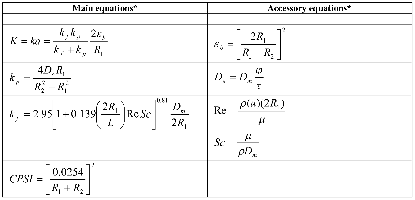
- the reaction rate, K is calculated using the mathematical relationship for monoliths reported in Rezaei and Webley (Rezaei and Webley, 2009, Optimum structured adsorbents for gas separation processes. Chemical Engineering Science, 64(24): 5182-5191.)
- the reaction rate, K is a function of the geometry of the monolith and the material properties and sorbent properties of the monolith. Sorbent properties are, for example, sorbent tortuosity and sorbent porosity. These sorbent properties define K, as shown in Table 2. [0047]
- the reaction rate, K can be calculated using the mathematical relationship for monoliths reported in Rezaei and Webley (2009), shown in Table 2:
- FIG. 1 is a schematic drawing of a cross-section of a channel of a monolith.
- FIG. 1 shows walls 100 forming a channel 101 extending along a length L from one end face 110 to a second end face 111 of a monolith.
- FIG. 1 illustrates Ri and R2.
- Ri and R2 are length dimensions.
- Ri is a channel radius.
- R2 is a channel radius plus the thickness of a channel wall.
- Ri represents flow in a channel.
- R2 represents flow in a channel, plus flow in a channel wall (see FIG. 1).
- K the reaction coefficient
- kf the film mass transfer coefficient
- k p the pore mass transfer coefficient
- reaction time scale (t r ) when the reaction time scale (t r ) is very small, S «l, the reaction occurs very quickly. If S « 1, then reaction time-scale is much smaller than the flow-rate time scale. Therefore, when S «l , the reaction time-scale is not dominating (or limiting) in the overall CO2 adsorption/desorption process. Instead, when S «l, flow rate is the dominating phenomenon.
- the flow time-scale is the time spent by a feed gas inside the reactor, defined by length of the reactor divided by the velocity of the gas in the channel.
- the effective mass transfer zone (henceforth referred as mtz) can be calculated as distance travelled by the feed within reaction time-scale, shown in Formula 2:
- reaction time and flow time are comparable, and both the reaction rate and the flow rate must be considered in calculating an appropriate monolith geometry for CO 2 adsorption and desorption.
- a comprehensive model which includes both reaction and flow, was solved for various input conditions to estimate the value of S when reaction is not dominating (or limiting). This is done by comparing the breakthrough time obtained by the comprehensive model (Zhang et al., 2008) with an analytical model (Equation. 4). Therefore, when reaction is not dominating, the analytical model should match closely with the comprehensive model. The error between the comprehensive model and the analytical model is close to 0% when reaction is not dominating. To estimate the value of S when reaction is not dominating, the error between analytical and comprehensive is plotted against S.
- FIG.4 is a graph plotting error (%) against design index, S, showing the error between Comprehensive and Analytical model predictions. As can be seen in FIG.
- the present disclosure provides a method for determining an optimal monolith geometry for a honeycomb monolith is provided, comprising the steps of:
- FIG. 5 is a graph plotting performance (calculated as the reciprocal of time to saturate the bed) with cell density (per square inch or CPSI), indicating the optimum CPSI, according to a model.
- FIG. 6 is a graph plotting the optimal cell density (CPSI) against the open frontal area of a monolith, showing the optimal cell density for various reactor sizes. The optimum cell density for various reactor sizes are shown. As the length and diameter decreases, the optimum cell density increases due to increase in velocity inside the monolith, (u or V/OFA). The effect of diameter on optimum cell density is more than length.
- Adsorbent is Zeolite 13X (extruded as monolith). If S « 1, then the breakthrough time is not a function of reaction rate.
- FIG. 7 is a graph showing normalized performance/normalized backpressure vs CPSI .
- a higher number for performance and low number for backpressure is desirable. Therefore, a high value on the y-axis of the graph shown in FIG. 7 is desirable.
- 500 cell-density gives the highest value. This gives a picture of optimization when two variables, adsorption kinetics and backpressure, are important.
- FIG. 9 is a graph illustrating normalized backpressure vs. normalized performance.
- optimal performance resides in the right lower corner, indicating high performance and low back-pressure.
- the backpressure increases with a very steep slope (meaning increase in backpressure is significant compared to increase in performance.
- FIG. 10 is a flow chart showing an embodiment of the disclosed method. According to Equation (1), for a given monolith size and length, flow rate, OFA, CPSI, and reaction rate, it is possible to characterize and calculate a Design Index, "S". Step (1) of the flow chart shown in FIG. 10 illustrates calculating S. Taking into account the parameters discussed above, and shown in 5 and FIGs. 7-9, an S of less than or equal to 0.4 is desirable, in embodiments. In additional
- an S of less than .35, less than or equal to.3, less than or equal to.25, less than or equal to.2, less than or equal to.15, less than or equal to. l , less than or equal to.05 or less than or equal to.01 are also desirable.
- step (2) as shown in FIG. 10, a determination can be made of whether S is at a desirable value or less.
- the monolith parameters may be changed to reduce S.
- Monolith parameters include geometric parameters including OFV, CPSI and length of the monolith.
- Monolith parameters also include system parameters such as gas velocity inside the monolith, gas velocity outside the monolith.
- Monolith parameters that affect overall adsorption rate (K) such wall thickness and channel size can also be changed.
- a monolith having an S value less than or equal to 0.1 is desirable because when the S value is less than or equal to 0.1, the flow time scale and not the reaction time scale is dominating.
- Monoliths having a range of S values from 0.1 to 0.4 are desirable.
- monoliths having S values less than or equal to 0.4, less than or equal to .35, less or equal to than .3, less or equal to than .25, less than or equal to.2, less than or equal to .15, less than or equal to .1, less than or equal to.05 or less than or equal to .01 are disclosed.
- the present disclosure provides a method for determining an optimal monolith geometry for a honeycomb monolith is provided, comprising the steps of:
- t r is the reaction time-scale
- tf is the flow time-scale
- u is the velocity of feed gas inside the channel
- K is the reaction rate
- L is the length of the reactor
- OFA is open frontal area
- V is the velocity of feed gas outside the monolith
- the desirable value of S may be, for example, 0.4, 0.35, 0.3, 0.25, 0.2, 0.15, 0.1, 0.05, or 0.01.
- the present disclosure provides a monolith for CO2 capture or separation having an S value equal to or less than 0.4, wherein S is defined by the formula:
- the S value may be equal to or less than 0.35, equal to or less than 0.30, equal to or less than 0.25, is equal to or less than 0.2, equal to or less than 0.15, equal to or less than 0.1, equal to or less than 0.05 or equal to or less than 0.01.
Landscapes
- Chemical & Material Sciences (AREA)
- Engineering & Computer Science (AREA)
- Analytical Chemistry (AREA)
- Chemical Kinetics & Catalysis (AREA)
- Organic Chemistry (AREA)
- Inorganic Chemistry (AREA)
- Oil, Petroleum & Natural Gas (AREA)
- General Chemical & Material Sciences (AREA)
- Physics & Mathematics (AREA)
- Theoretical Computer Science (AREA)
- General Engineering & Computer Science (AREA)
- Manufacturing & Machinery (AREA)
- Computer Hardware Design (AREA)
- Evolutionary Computation (AREA)
- Geometry (AREA)
- Ceramic Engineering (AREA)
- General Physics & Mathematics (AREA)
- Mechanical Engineering (AREA)
- Solid-Sorbent Or Filter-Aiding Compositions (AREA)
- Separation Of Gases By Adsorption (AREA)
- Architecture (AREA)
- Software Systems (AREA)
- Carbon And Carbon Compounds (AREA)
Abstract
Description

Claims
Priority Applications (4)
| Application Number | Priority Date | Filing Date | Title |
|---|---|---|---|
| CN201280067635.2A CN104203517A (en) | 2011-11-30 | 2012-11-29 | Monolith geometry design for carbon dioxide capture |
| US14/361,121 US9477788B2 (en) | 2011-11-30 | 2012-11-29 | Monolith geometry design for carbon dioxide capture |
| AU2012345954A AU2012345954A1 (en) | 2011-11-30 | 2012-11-29 | Monolith geometry design for carbon dioxide capture |
| JP2014544883A JP2015511166A (en) | 2011-11-30 | 2012-11-29 | Monolith geometry design for carbon dioxide capture |
Applications Claiming Priority (2)
| Application Number | Priority Date | Filing Date | Title |
|---|---|---|---|
| US201161565122P | 2011-11-30 | 2011-11-30 | |
| US61/565,122 | 2011-11-30 |
Publications (1)
| Publication Number | Publication Date |
|---|---|
| WO2013082278A1 true WO2013082278A1 (en) | 2013-06-06 |
Family
ID=48536050
Family Applications (1)
| Application Number | Title | Priority Date | Filing Date |
|---|---|---|---|
| PCT/US2012/067051 Ceased WO2013082278A1 (en) | 2011-11-30 | 2012-11-29 | Monolith geometry design for carbon dioxide capture |
Country Status (5)
| Country | Link |
|---|---|
| US (1) | US9477788B2 (en) |
| JP (1) | JP2015511166A (en) |
| CN (1) | CN104203517A (en) |
| AU (1) | AU2012345954A1 (en) |
| WO (1) | WO2013082278A1 (en) |
Cited By (1)
| Publication number | Priority date | Publication date | Assignee | Title |
|---|---|---|---|---|
| WO2024086036A1 (en) * | 2022-10-20 | 2024-04-25 | Corning Incorporated | Monolithic substrates |
Families Citing this family (2)
| Publication number | Priority date | Publication date | Assignee | Title |
|---|---|---|---|---|
| CN116348412A (en) | 2020-06-09 | 2023-06-27 | 全球温控营运有限责任公司 | Continuous Motion Direct Air Capture System |
| JP2025518138A (en) | 2022-05-27 | 2025-06-12 | ゼロ カーボン システムズ インコーポレイテッド | High Throughput Moving Panel Direct Air Capture System |
Citations (1)
| Publication number | Priority date | Publication date | Assignee | Title |
|---|---|---|---|---|
| US20070207917A1 (en) * | 2006-02-14 | 2007-09-06 | Chester Wayne Sink | Activated carbon monoliths and methods of making them |
Family Cites Families (19)
| Publication number | Priority date | Publication date | Assignee | Title |
|---|---|---|---|---|
| CN100523805C (en) | 2006-05-25 | 2009-08-05 | 重庆大学 | Pressure investigating method for deabsorbent dynamic parameter of adsorbent-gas system |
| US20080148936A1 (en) * | 2006-12-22 | 2008-06-26 | Mohamed Safdar Allie Baksh | Composite structured adsorbents |
| CN101214151B (en) * | 2007-12-29 | 2010-08-18 | 广州医学院第一附属医院 | Method and device for pressure dividing monitoring and estimating arterial blood CO2 by using respiratory gas CO2 |
| US8496734B2 (en) | 2009-02-26 | 2013-07-30 | Corning Incorporated | Sorbent structure applicable for carbon dioxide capture |
| US8500880B2 (en) | 2009-11-24 | 2013-08-06 | Corning Incorporated | Amino acid salt articles and methods of making and using them |
| US8163069B2 (en) | 2009-11-24 | 2012-04-24 | Corning Incorporated | Carboxylic acid salt articles and methods of making and using them |
| EP2563495B1 (en) * | 2010-04-30 | 2019-09-25 | Peter Eisenberger | Method for carbon dioxide capture |
| US8647412B2 (en) | 2011-02-28 | 2014-02-11 | Corning Incorporated | Sorbent articles for CO2 capture |
| EP2680939A1 (en) | 2011-02-28 | 2014-01-08 | Corning Incorporated | Article for carbon dioxide capture |
| US9011583B2 (en) | 2011-04-29 | 2015-04-21 | Corning Incorporated | Article for CO2 capture having heat exchange capability |
| US8858690B2 (en) | 2011-08-24 | 2014-10-14 | Corning Incorporated | Thermally integrated adsorption-desorption systems and methods |
| US8728218B2 (en) | 2011-09-15 | 2014-05-20 | Corning Incorporated | Sorbent substrates for CO2 capture and methods for forming the same |
| US20130207034A1 (en) | 2012-02-09 | 2013-08-15 | Corning Incorporated | Substrates for carbon dioxide capture and methods for making same |
| US9073000B2 (en) | 2012-03-14 | 2015-07-07 | Corning Incorporated | Segmented reactors for carbon dioxide capture and methods of capturing carbon dioxide using segmented reactors |
| US9062586B2 (en) | 2012-04-05 | 2015-06-23 | Corning Incorporated | Impermeable polymer coating on selected honeycomb channel surfaces |
| WO2014105456A1 (en) | 2012-12-28 | 2014-07-03 | Corning Incorporated | Shaped articles and methods for making the same |
| US8974577B2 (en) | 2013-04-23 | 2015-03-10 | Corning Incorporated | Sorbent compositions, sorbent articles, methods for preparing sorbent articles, and methods for capturing target gases using the sorbent articles |
| WO2015054332A1 (en) | 2013-10-10 | 2015-04-16 | Corning Incorporated | Composite honeycombs for gas storage |
| WO2015080998A1 (en) | 2013-11-26 | 2015-06-04 | Corning Incorporated | Laminates for rapid co2 capture from gas mixtures |
-
2012
- 2012-11-29 JP JP2014544883A patent/JP2015511166A/en not_active Abandoned
- 2012-11-29 US US14/361,121 patent/US9477788B2/en not_active Expired - Fee Related
- 2012-11-29 CN CN201280067635.2A patent/CN104203517A/en active Pending
- 2012-11-29 WO PCT/US2012/067051 patent/WO2013082278A1/en not_active Ceased
- 2012-11-29 AU AU2012345954A patent/AU2012345954A1/en not_active Abandoned
Patent Citations (1)
| Publication number | Priority date | Publication date | Assignee | Title |
|---|---|---|---|---|
| US20070207917A1 (en) * | 2006-02-14 | 2007-09-06 | Chester Wayne Sink | Activated carbon monoliths and methods of making them |
Non-Patent Citations (2)
| Title |
|---|
| CHEN ET AL.: "Mathematical modeling of monolith catalysts and reactors for gas phase reactions", APPLIED CATALYSIS A: GENERAL, vol. 345, no. 1, 2008, pages 1 - 11, XP022765285 * |
| FERRIZZ ET AL.: "Monolithic Supports with Unique Geometries and Enhanced Mass Transfer", IND. ENG. CHEM. RES., vol. 44, no. 2, January 2004 (2004-01-01), pages 302 - 308, XP055070659 * |
Cited By (1)
| Publication number | Priority date | Publication date | Assignee | Title |
|---|---|---|---|---|
| WO2024086036A1 (en) * | 2022-10-20 | 2024-04-25 | Corning Incorporated | Monolithic substrates |
Also Published As
| Publication number | Publication date |
|---|---|
| JP2015511166A (en) | 2015-04-16 |
| US9477788B2 (en) | 2016-10-25 |
| CN104203517A (en) | 2014-12-10 |
| US20140367611A1 (en) | 2014-12-18 |
| AU2012345954A1 (en) | 2014-07-03 |
Similar Documents
| Publication | Publication Date | Title |
|---|---|---|
| Jee et al. | Adsorption characteristics of hydrogen mixtures in a layered bed: binary, ternary, and five-component mixtures | |
| Abdeljaoued et al. | Simulation and experimental results of a PSA process for production of hydrogen used in fuel cells | |
| Lopes et al. | Adsorption of H2, CO2, CH4, CO, N2 and H2O in activated carbon and zeolite for hydrogen production | |
| Hasan et al. | Cost-effective CO 2 capture based on in silico screening of zeolites and process optimization | |
| Morales-Ospino et al. | Assessment of CO2 desorption from 13X zeolite for a prospective TSA process | |
| Haghpanah et al. | Multiobjective optimization of a four-step adsorption process for postcombustion CO2 capture via finite volume simulation | |
| Ribeiro et al. | A parametric study of layered bed PSA for hydrogen purification | |
| Casas et al. | A parametric study of a PSA process for pre-combustion CO2 capture | |
| Boone et al. | Designing optimal core–shell MOFs for direct air capture | |
| Ahn et al. | Effects of capillary condensation on adsorption and thermal desorption dynamics of water in zeolite 13X and layered beds | |
| Lawson et al. | Effects of process parameters on CO2/H2 separation performance of 3D-printed MOF-74 monoliths | |
| Ribeiro et al. | Four beds pressure swing adsorption for hydrogen purification: case of humid feed and activated carbon beds | |
| Ahn et al. | Adsorption dynamics of water in layered bed for air-drying TSA process | |
| US9073000B2 (en) | Segmented reactors for carbon dioxide capture and methods of capturing carbon dioxide using segmented reactors | |
| Daff et al. | Evaluation of carbon nanoscroll materials for post-combustion CO2 capture | |
| Fakhroleslam et al. | Comparative simulation study of PSA, VSA, and TSA processes for purification of methane from CO2 via SAPO-34 core-shell adsorbent | |
| WO2013082278A1 (en) | Monolith geometry design for carbon dioxide capture | |
| Mattox et al. | Carbon dioxide removal system for closed loop atmosphere revitalization, candidate sorbents screening and test results | |
| Walton et al. | A novel adsorption cycle for CO2 recovery: Experimental and theoretical investigations of a temperature swing compression process | |
| Akhtar et al. | Thin zeolite laminates for rapid and energy-efficient carbon capture | |
| Peh et al. | Direct contact TSA cycle based on a hydrophobic MOF sorbent for post-combustion CO2 capture from wet flue gas | |
| Jee et al. | Effects of nonisobaric and isobaric steps on O2 pressure swing adsorption for an aerator | |
| Kim et al. | Parametric study of pressure swing adsorption process to purify oxygen using carbon molecular sieve | |
| Zhang et al. | Optimization of pressure swing adsorption in a three-layered bed for hydrogen purification using machine learning model | |
| Claessens | How does structured adsorbent channel heterogeneity influence the efficiency of adsorptive CO2 capture? |
Legal Events
| Date | Code | Title | Description |
|---|---|---|---|
| 121 | Ep: the epo has been informed by wipo that ep was designated in this application |
Ref document number: 12854525 Country of ref document: EP Kind code of ref document: A1 |
|
| WWE | Wipo information: entry into national phase |
Ref document number: 14361121 Country of ref document: US |
|
| ENP | Entry into the national phase |
Ref document number: 2014544883 Country of ref document: JP Kind code of ref document: A |
|
| NENP | Non-entry into the national phase |
Ref country code: DE |
|
| ENP | Entry into the national phase |
Ref document number: 2012345954 Country of ref document: AU Date of ref document: 20121129 Kind code of ref document: A |
|
| 122 | Ep: pct application non-entry in european phase |
Ref document number: 12854525 Country of ref document: EP Kind code of ref document: A1 |