WO2013076933A1 - Wireless telecommunication network - Google Patents
Wireless telecommunication network Download PDFInfo
- Publication number
- WO2013076933A1 WO2013076933A1 PCT/JP2012/007281 JP2012007281W WO2013076933A1 WO 2013076933 A1 WO2013076933 A1 WO 2013076933A1 JP 2012007281 W JP2012007281 W JP 2012007281W WO 2013076933 A1 WO2013076933 A1 WO 2013076933A1
- Authority
- WO
- WIPO (PCT)
- Prior art keywords
- relay node
- base station
- type
- enb
- wireless communication
- Prior art date
- Legal status (The legal status is an assumption and is not a legal conclusion. Google has not performed a legal analysis and makes no representation as to the accuracy of the status listed.)
- Ceased
Links
Images


Classifications
-
- H—ELECTRICITY
- H04—ELECTRIC COMMUNICATION TECHNIQUE
- H04W—WIRELESS COMMUNICATION NETWORKS
- H04W36/00—Hand-off or reselection arrangements
- H04W36/0005—Control or signalling for completing the hand-off
-
- H—ELECTRICITY
- H04—ELECTRIC COMMUNICATION TECHNIQUE
- H04B—TRANSMISSION
- H04B7/00—Radio transmission systems, i.e. using radiation field
- H04B7/14—Relay systems
- H04B7/15—Active relay systems
-
- H—ELECTRICITY
- H04—ELECTRIC COMMUNICATION TECHNIQUE
- H04W—WIRELESS COMMUNICATION NETWORKS
- H04W36/00—Hand-off or reselection arrangements
- H04W36/0005—Control or signalling for completing the hand-off
- H04W36/0011—Control or signalling for completing the hand-off for data sessions of end-to-end connection
- H04W36/0016—Hand-off preparation specially adapted for end-to-end data sessions
-
- H—ELECTRICITY
- H04—ELECTRIC COMMUNICATION TECHNIQUE
- H04W—WIRELESS COMMUNICATION NETWORKS
- H04W36/00—Hand-off or reselection arrangements
- H04W36/0005—Control or signalling for completing the hand-off
- H04W36/0055—Transmission or use of information for re-establishing the radio link
- H04W36/0061—Transmission or use of information for re-establishing the radio link of neighbour cell information
-
- H—ELECTRICITY
- H04—ELECTRIC COMMUNICATION TECHNIQUE
- H04W—WIRELESS COMMUNICATION NETWORKS
- H04W84/00—Network topologies
- H04W84/02—Hierarchically pre-organised networks, e.g. paging networks, cellular networks, WLAN [Wireless Local Area Network] or WLL [Wireless Local Loop]
- H04W84/04—Large scale networks; Deep hierarchical networks
- H04W84/042—Public Land Mobile systems, e.g. cellular systems
- H04W84/045—Public Land Mobile systems, e.g. cellular systems using private Base Stations, e.g. femto Base Stations, home Node B
-
- H—ELECTRICITY
- H04—ELECTRIC COMMUNICATION TECHNIQUE
- H04W—WIRELESS COMMUNICATION NETWORKS
- H04W84/00—Network topologies
- H04W84/02—Hierarchically pre-organised networks, e.g. paging networks, cellular networks, WLAN [Wireless Local Area Network] or WLL [Wireless Local Loop]
- H04W84/04—Large scale networks; Deep hierarchical networks
- H04W84/042—Public Land Mobile systems, e.g. cellular systems
- H04W84/047—Public Land Mobile systems, e.g. cellular systems using dedicated repeater stations
Definitions
- the present invention relates to a relay node, and a wireless telecommunication system including same. Particularly, The present invention relates to the C-plane (control plane) handling of a Mobile Relay Handover needed for out-band, in-band relay types with or without resource partitioning as applicable in the context of 3GPP Long Term Evolution (LTE)-Advanced.
- C-plane control plane
- LTE Long Term Evolution
- the first release of the LTE was referred to as release-8, and provided a peak rate of 300 Mbps, a radio network delay of less than 5ms, an increase in spectrum efficiency and new architecture to reduce cost and simplify operation.
- LTE-A or LTE Advanced is currently being standardized by the 3GPP as an enhancement of LTE.
- LTE mobile communication systems are expected to be deployed from 2010 onwards as a natural evolution of GSM and UMTS.
- LTE Being defined as 3.9G (3G+) technology, LTE does not meet the requirements for 4G, also called IMT Advanced, that has requirements such as peak data rates up to 1 Gbps.
- LTE Long Term Evolution
- FIG. 1 shows a simplified example of part of the LTE network.
- a base station typically called an evolved node B (eNB) 10, a relay node (RN) 14 and a plurality of user equipment (UE) 18 and 20.
- eNB evolved node B
- RN relay node
- UE user equipment
- a controlling eNB is sometimes referred to as a donor eNB, or D-eNB.
- D-eNB controls network traffic within a domain (containing one or more cells). Said domain may include a plurality of further nodes. Domains located geographically next to one another may be termed neighbouring domains.
- the D-eNB is typically wired to the core network 16. This connection is often termed the eNB's backhaul.
- the D-eNB can communicate wirelessly with UE 18. This connection is termed the access link.
- the D-eNB 10 can also communicate with UE 20 via RN 14.
- the RN 14 thus has an access link to UE 20 and a backhaul link to the D-eNB.
- the access link is via the Uu interface, whilst the backhaul link is via the Un interface.
- a communication from a UE or node back towards the core network is called the uplink (sometimes abbreviated to UL), whereas communication in the opposite direction (i.e. D-eNB or RN to UE) is called the downlink (sometimes abbreviated to DL).
- the communication from the RN to the D-eNB is the downlink in respect to the RN, whilst the reciprocal communication is the uplink.
- relays are broadly defined in two categories: type 1 and type 2.
- Type 1 relay nodes have their own PCI (Physical Cell ID) and are operable to transmit its common channel/signals. UEs receive scheduling information and HARQ feedback directly from the relay node. It is also possible for type 1 relay nodes to appear differently to eNBs to allow for further performance enhancement.
- Type 1 relays may be considered as containing the functionalities of both an eNB (control node) and UE (user equipment), depending on how its functionalities are viewed.
- the relay behaves like a UE (which is operated by the functionality of a UE), whereas in the access link it behaves like an eNB (which is operated by the functionality of an eNB).
- the D-eNB sees the relay as a UE, whereas the UE sees the relay as an ordinary eNB.
- Type 1 relays are further categorized into Type 1, Type 1a and Type 1b. Within the Rel-10 timeframe, RNs that are of type-1, 1a and 1b are predominantly considered.
- the RN connects to the D-eNB via the Un interface using the same radio protocols and procedures as a UE connecting to an eNB.
- Rel-10 RN is fundamentally classified into:
- Type 1 (In band) Relaying - in which case the Un interface shares the same carrier frequency with RN-UE link and it is not capable of isolating the outgoing and incoming signals. In this case, isolation is performed in the time domain. Some of the subframes are reserved for the backhaul link and cannot be used for the access link operation;
- Type 1a (Out band) Relaying - in which case the Un interface does not operate in the same carrier frequency as RN-UE link and subframe configuration is not required for the communication over Un interface. In this case, isolation is performed in the frequency domain;
- Type 1b in band with antenna isolation
- Relay operation happens in-band, but isolation is not performed in the time domain, but via adequate antenna configuration.
- In-band relay operation is more complex, since isolation in the time domain needs sophisticated configuration of the Un interface.
- out-band relay operation is more straightforward, since it only requires adequate frequency planning.
- the backhaul link gets assigned the lower carrier frequency, such that it suffers less from distance-dependent attenuation and can be located close to the edge of the macro cell.
- no additional functionality beyond Rel-8 is required, i.e., the Un interface behaves in the same way as a legacy Uu link.
- In-band relaying operation without adequate antenna isolation requires reservation of certain subframes for the backhaul link.
- the blocking of UE transmissions is straightforward, since the RN performs the uplink grant scheduling itself and therefore has full control over when it wants to transmit and receive data.
- the D-eNB needs to ascertain whether Un subframe configuration/reconfiguration (i.e., RN requiring one type of Un resource partitioning) should be applied on Un interface or not for a given RN.
- Un subframe configuration/reconfiguration i.e., RN requiring one type of Un resource partitioning
- subframes need to be configured such that half-duplex operation can be ensured in the case of Type 1 relays.
- the RRC layer (the radio resource control) of the Un interface has functionality to configure or reconfigure and activate specific subframe configurations (e.g. DL subframe configuration) for transmissions between an RN and a D-eNB, for RNs of Type 1. This means that the D-eNB needs to be aware of RN's type before initiating the RRC signalling for such configurations. The RN applies the configuration immediately upon reception.
- Type A relays are in band that operate in half-duplex mode - i.e., when the access link is operational the backhaul cannot operate and vice-versa.
- Main downlink transmission occurs on the backhaul on MBSFN sub-frames.
- MBSFN sub-frames cannot be configured in the downlink on sub-frames 0, 4, 5 and 9: this sub-frame configuration concerns making the backhaul and access link function without interference.
- Time-frequency resources for eNB-RN transmissions are achieved by time multiplexing eNB-RN and RN-UE transmissions. Subframes during which eNB-RN transmission may take place are configured by higher layers. Downlink subframes configured for eNB-to-RN transmission shall be configured as MBSFN subframes by the relay node. eNB-to-RN transmissions occur in downlink subframes and RN-to-eNB transmissions occur in uplink subframes. For frame structure type 1, eNB-to-RN and RN-to-UE transmissions occur in the downlink frequency band, while RN-to-eNB and UE-to-RN transmissions occur in the uplink frequency band. (Reference: 3GPP TS 36.216)
- Downlink subframes configured for eNB-to-RN transmission shall be configured as MBSFN subframes by the relay node;
- Relay-to-D-eNB transmissions can be facilitated by not allowing any UE-to-relay transmissions in some subframes;
- Subframes during which eNB-RN transmission may take place are configured by higher layers.
- MME mobility management entity
- a UE is associated to one particular MME for its communications. This creates a context in this MME for the UE. This particular MME is selected by NAS Node Selection Function (NNSF) in the first eNB from which the UE enters the network. Whenever a UE becomes active, the MME provides the UE context information to the eNB.
- NSF NAS Node Selection Function
- a relay-MME works in a similar manner, but relates to RNs, rather than UEs.
- the present invention seeks advancements to relaying technology, specifically with relation to how mobile relaying can improve network performance.
- Relay types (especially Type 1 and 1a) defined by the 3GPP are tied to their capability in terms of the number of transceivers a relay node is equipped with, their operating frequency range, and whether the relay node can support full/half-duplex operation. If a relay node (RN) comprises more than one transceiver it will have the capability to operate in different frequency bands simultaneously on both the access link and the backhaul link. However, there is a possibility for a relay node to be Type-1 when it is attached to one D-eNB (say, a source D-eNB) but operate in Type-1a type/mode when it is attached to a different D-eNB (say, Target D-eNB).
- D-eNB say, a source D-eNB
- Target D-eNB Target D-eNB
- D-eNBs and RNs operate with different frequency spectrums, and as such a given RN may be regarded by one eNB as being one particular type, but seen by a different eNB to be a different type. The main occasions when this will occur are between type 1 and type 1a RNs.
- the present invention seeks to introduce efficiencies and advancements within the network.
- a wireless communication network comprising:
- relay node being one of a plurality of types present within the network
- said relay node is connected to the first base station
- said first base station when handover is required, sends a handover request to the second base station of information pertaining to the handover, including information regarding the relay node's type.
- a relay node operable to function in a wireless communications network, said relay node being one of a plurality of types possible within said wireless communications network, wherein the relay node is operable to handover its backhaul link from a first base station to a second base station, wherein information regarding the relay node's type is communicated to the second base station.
- a base station operable to function within a wireless communications network, said base station comprising a wireless link to a relay node, said relay node being one type within a plurality of types with the wireless communications network, wherein said base station is operable to handover the wireless link to a further base station, wherein the handover includes details of the relay node's type.
- a wireless telecommunications network comprising:
- the relay node when the relay node has cause to attach to the wireless telecommunications network, either 1) it communicates its type to said base station, or 2) the core network communicates the relay node's type to the base station.
- Figure 1 shows an example of LTE-A network architecture incorporating a static relay.
- Figure 2 shows an example of LTE-A network architecture incorporating a mobile relay.
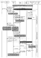
- Figure 3 is a diagram showing intra-MME/serving gateway handover procedure as applicable to the present arrangement.
- Figure 4 is a diagram showing a signalling diagram showing a handover procedure as applicable to the present arrangement.
- the present invention is primarily concerned with mobile relay attachment and handover within the LTE-A wireless networks.
- the present arrangement is applicable to static relay nodes when said static relay node is subject to a handover between base stations for load balancing purposes.
- relay nodes may be passed from one base station to a second base station. This is termed a handover.
- the first base station is termed a source D-eNB, whilst the second base station is termed a target D-eNB.
- LTE-A networks can comprise multiple types of relay nodes (e.g. type 1, type 1a, type 1b, type 2, repeaters) it is important when a relay node (RN) attaches to D-eNB or is handed over from one D-eNB to another that the relevant D-eNB can readily ascertain the RN's type.
- RN relay node
- Different relay nodes may have different capabilities which effect the way they operate within the network. Relevant information on RN capability includes:
- a source D-eNB can inform a target D-eNB as to how many component carriers the RN is capable of operating in the downlink and the uplink.
- the information can be provided to the D-eNB or to a target D-eNB from the MME serving the RN by means of S1 signalling. This information is used by a target D-eNB for optimum carrier configuration for the backhaul link.
- Resource Partitioning may be decided individually for each component carrier, if needed.
- the passed on information passed on may also contain a given RN's eNB-like capability details on supported multi-carrier operation schemes - it may include:
- RNs relay nodes
- Such RNs are typically termed mobile relays.
- mobile relays have recently started drawing the attention of the 3gpp because of their ability to minimize or completely avoid the high and bursty signalling load at the time of group mobility.
- a mobile relay being mounted on a vehicle can perform a group mobility instead of individual mobility procedures for every user equipment (UE).
- UEs connected to a mobile relay do not have to individually handover between D-eNBs as they pass through different domains; the mobile relay can maintain connection with each UE and handover its backhaul link between D-eNBs.
- the actual relay type(s) for mobile relays is not finalized by the 3GPP, it is acknowledged that it would be advantageous if they are equipped with advanced antenna systems. Hence their spectral efficiency would be superior to that of a normal UE. Separate antennas for the backhaul and the access link can improve the performance.
- mobile relays will also be categorized into different types - it can be in line with the existing categorization as outlined in the previous paragraphs or can support entirely new categorization. However, it is very likely that the RNs may be either in-band or out-band.
- FIG 2 shows an example of LTE architecture with a mobile relay.
- mobile RN 14 is mounted on train 16.
- trains travel at high speeds, and as such will pass through multiple domains (or cells), and as such have to interact with multiple D-eNBs 10, 12.
- RN 14 is connected to D-eNB 10, but as it moves away from this node and towards D-eNB 12, it will becomes necessary for the RN to be handed over from D-eNB 10 to D-eNB 12.
- a mobile RN handover is a common occurrence, and consideration has to be made for a mechanism for a target D-eNB 12 to ascertain the relay type before it can decide whether or not it can support the relay to be handed over.
- the target D-eNB 12 has to quickly decide on whether any type of resource partitioning is needed (e.g., in the form of subframe configuration).
- pre-configured RN-D-eNB pair pre-configured pairs of D-eNB - RN are for static RNs that will always be in communication with the same D-eNB, and as such the subframes on the RNs backhaul will always be configured
- a D-eNB in case of a mobile relay attachment or for a target D-eNB in case of a relay handover, to configure subframes or partition resources dynamically, depending on the mobile relay type and/or its capabilities in terms of frequency-bands or radio access technologies (RATs) being supported, full-/half-duplex operation being possibly, carrier-aggregation support and the like.
- RATs radio access technologies
- the present arrangement proposes a methodology to achieve this while making sure that it is in conformity with existing network protocols.
- a modified UE capability container is part of the UE capability transfer procedure.
- the E-UTRAN can indicate for each RAT whether it wants to receive associated capabilities of UE.
- a UE provides the requested capabilities using a separate container for each RAT). In the present case the RN would use a RN capability container.
- the second option is for the core network (e.g., OAM, EPC, Relay-MME) to pass the RN's operating frequencies on to the D-eNB 12 at the time of mobile relay attachment or relay handover.
- the core network can include the type in the RN/UE context as the establishment and the modification of UE/RN context is initiated by an MME - a Rel-8/9 UE context normally includes E-RAB quality of service and transport parameters, security context (cipher key), handover restriction, trace activation, CSFB, SRVCC ops status, UE radio and security capabilities.
- the D-eNB 12 will configure the mobile RN 14 depending on its capabilities, and the extent of support that it can provide.
- a wireless telecommunications network that includes a mobile RN of one of a plurality of types (ie type 1, type 1a, type 1b etc) and a base station.
- the RN When the RN has cause to attach to the wireless telecommunications network, either 1) it communicates its type to the D-eNB (base station), or 2) the core network communicates the RN's type to the D-eNB (base station).
- the Source D-eNB 10 For mobile relay handover, it is appropriate for the Source D-eNB 10 to pass the relay type onto the target D-eNB 12 with/without additional details such as different radio access technologies (RATs) being supported by a given relay and whether a given RN can operate in half-duplex or full-duplex mode in the frequency domain, time domain or space domain under each RAT, and the frequency bands the RN can support under each RAT including how many component carriers the RN is capable of operating in the downlink and the uplink of the backhaul, and the RN's eNB-like capability details on supported multi-carrier operation on the backhaul.
- RATs radio access technologies
- the type of the mobile relay and/or its capability details can be included as part of Handover Request parameters and notified to the target D-eNB 12.
- the above concepts are also equally applicable to fixed (static) relays, given that a fixed relay may be handed over to a neighbouring D-eNB due to load-balancing purposes.
- the present arrangement relates to a wireless communication network, such as an LTE-A network.
- the network includes a first base station and a second base station, which are typically eNBs that are capable of supporting relays.
- the network also comprises a relay node being one of a plurality of types present within the network (e.g. type 1, type 1a, type 1b or type 2).
- the relay node is connected to the first base station such that, when handover a is required, said first base station sends a handover request to the second base station of information pertaining to the handover, including information regarding the relay node's type and/or a given relay's capability details.
- the arrangement is particularly relevant to mobile relays, due to their frequent need to pass between base stations (D-eNBs).
- the first base station/eNB is operable to send to the second base station/eNB a relay node capability container for each RAT being supported by a relay in the handover request.
- This mechanism is similar to a source eNB sending a target D-eNB a UE capability container in a UE handover.
- the second base station can request the relay node capability container from the first base station on demand.
- second base station Another possibility for a target D-eNB (second base station) is to acquire the relay node capability container from the core network.
- second base station is operable to demand one or a plurality of radio capability details of the RN, such as different radio access technologies (RATs) being supported by the relay node, and whether the RN can operate in half-duplex or full-duplex mode in the frequency domain, time domain or space domain under each RAT, and the frequency bands the RN can support under each RAT, including how many component carriers the RN is capable of operating in the downlink and the uplink of the backhaul, and the RN's eNB-like capability details on supported multi-carrier operation on the backhaul from the core network (e.g., OAM, EPC, Relay-MME).
- RATs radio access technologies
- relay architecture A (Alt1) that is inline with the 3GPP TS 36.300. Further details about different relay architectures may be found in the present applicant's application number GB 2475906. The numbering of each step refers to the steps illustrated in figure 3. Where possible, wording used in TS 36300 has been maintained.
- the UE/RN context within the source D-eNB contains information regarding roaming restrictions which were provided either at connection establishment or at the last TA update.
- the source D-eNB configures the UE/RN measurement procedures according to the area restriction information. Measurements provided by the source D-eNB may assist the function controlling the UE's/RN's connection mobility.
- the UE/RN is triggered to send MEASUREMENT REPORT by the rules set by i.e. system information, specification etc.
- the source D-eNB makes decision based on MEASUREMENT REPORT and RRM information to hand off the UE/RN.
- the source D-eNB issues a HANDOVER REQUEST message to the target D-eNB passing necessary information to prepare the handover at the target side (relay type and/or a capability container including details such as different radio access technologies (RATs) being supported by a given relay and whether a given RN can operate in half-duplex or full-duplex mode in the frequency domain, time domain or space domain under each RAT, and the frequency bands the RN can support under each RAT including how many component carriers the RN is capable of operating in the downlink and the uplink of the backhaul, and the RN's eNB-like capability details on supported multi-carrier operation on the backhaul, UE X2 signalling context reference at source eNB, UE S1 EPC signalling context reference, target cell ID, KeNB*, RRC context including the C-RNTI of the UE/RN in the source D-eNB, AS-configuration, E-RAB context and physical layer ID of the source cell + short MAC-I for possible RLF recovery).
- the E-RAB context includes necessary RNL and TNL addressing information, and QoS profiles of the E-RABs.
- the target D-eNB On receiving the HO Request along with the information as to the type along with a radio capabilities of relay node being handed over, the target D-eNB will examine the relay's capability based on the information being passed on in the capability container and deciding its supported relay type.
- Admission Control may be performed by the target D-eNB dependent on the received RN type and its resource configuration details gathered as part of 4a/b stage above and E-RAB QoS information to increase the likelihood of a successful HO, if the resources can be granted by target D-eNB.
- the target D-eNB configures the required resources according to the received RN type and E-RAB QoS information and reserves a C-RNTI and optionally a RACH preamble.
- the AS-configuration to be used in the target cell can either be specified independently (i.e. an "establishment") or as a delta compared to the AS-configuration used in the source cell (i.e. a "reconfiguration").
- the target D-eNB prepares HO with L1/L2 and sends the HANDOVER REQUEST ACKNOWLEDGE to the source D-eNB.
- the HANDOVER REQUEST ACKNOWLEDGE message includes a transparent container to be sent to the UE/RN as an RRC message to perform the handover.
- the container includes a new C-RNTI, target D-eNB security algorithm identifiers for the selected security algorithms, may include a dedicated RACH preamble, control channel configuration and other control information that is normally carried by a MIB/SIBs, and possibly some other parameters i.e. access parameters, SIBs, etc.
- the HANDOVER REQUEST ACKNOWLEDGE message may also include RNL/TNL information for the forwarding tunnels, if necessary.
- Steps 7 to 16 provide means to avoid data loss during HO and are further detailed in 10.1.2.1.2 and 10.1.2.3 of 3GPP TS 36.300, (and are incorporated herein by reference).
- the relay type can be included in the Forward Relocation Request being originated by Source Relay-MME destined to Target Relay-MME.
- the arrangement illustrated in figure 4 is related to that shown in figure 3, except that the information regarding relay type and the RN capability container information are not passed from the source D-eNB to the source D-eNB in the initial handover request. Instead, required information is fetched by the target D-eNB on demand in the following two steps:
- the target D-eNB On receiving the HO Request along with the information as to the type of relay node being handed over, the target D-eNB issue a new message to acquire further capability details of the RN either from a source D-eNB (shown in Figure 4) or from the core/EPC (not shown) once the relay identifier is known.
- RATs radio access technologies
- either the source D-eNB or the core network (e.g., EPC) will supply the RN capability container according to the request.
- the system have to have the source D-eNB initially pass the relay type to the target D-eNB, and await a request from the target D-eNB for further information.
- a wireless communication network comprising:
- relay node being one of a plurality of types present within the network
- said relay node is connected to the first base station
- said first base station when handover is required, sends a handover request to the second base station of information pertaining to the handover, including information regarding the relay node's type.
- the first base station and the second base station are evolved nodeBs - typically termed eNBs. It is particularly desirable that the network is an LTE-A network.
- the first eNB base station
- the second eNB base station
- the target D-eNB the target D-eNB.
- the first base station may include an RN capability container in the Handover Request that indicates different radio access technologies (RATs) being supported by the RN and whether the RN can operate in half-duplex or full-duplex mode in the frequency domain, time domain or space domain under each RAT, and the frequency bands the RN can support under each RAT including how many component carriers the RN is capable of operating in the downlink and the uplink of the backhaul, and the RN's eNB-like capability details on supported multi-carrier operation on the backhaul.
- RATs radio access technologies
- the second base station after receipt of the handover request, requests the first base station to send a relay node capability container.
- the second base station issues a request to the first base station (source D-eNB) to acquire subframe configuration/reconfiguration and/or resource partitioning details.
- the second base station issues a request to the first base station (source D-eNB) to acquire subframe configuration/reconfiguration and/or resource partitioning details if the relay node is a type 1 relay.
- the wireless communications network further comprises a core network, and after receipt of the handover request, the second base station requests the core network to supply a relay node capability container.
- the second base station may issue a request to the core network to acquire subframe configuration/reconfiguration and/or resource partitioning details and/or an RN capability container to indicate different radio access technologies (RATs) being supported by the RN, and whether the RN can operate in half-duplex or full-duplex mode in the frequency domain, time domain or space domain under each RAT, and the frequency bands the RN can support under each RAT including how many component carriers the RN is capable of operating in the downlink and the uplink of the backhaul, and the RN's eNB-like capability details on supported multi-carrier operation on the backhaul.
- RATs radio access technologies
- the relay node is a mobile relay node. It is particularly preferred that the mobile relay node is mounted upon a public transport vehicle, with it being specifically desirable for the mobile relay node to be mounted upon a train. However, it will be appreciated that the mobile relay may be mounted upon any vehicle
- the relay node is of type 1, type 1a or type 1b.
- other relay types - such as type 2 - are possible within the present arrangement.
- the present invention also relates to a relay node operable to function within the above described wireless communication network, and also to a base station that may operate in the capacity of either the first base station or the second base station
- a wireless telecommunications network comprising:
- the relay node when the relay node has cause to attach to the wireless telecommunications network, either 1) it communicates its type to said base station, or 2) the core network communicates the relay node's type to the base station.
- the above aspect relates to relay attachment to a wireless network.
- the network is an LTE network
- the relay node is a mobile node and particularly of type 1, type 1a or type 1b
- the base stations are eNBs.
- the present arrangement is particularly relevant in LTE-A, although it may be applied for WiMAX (both IEEE 802.16e and IEEE 802.20) and Long range WiFi.
Landscapes
- Engineering & Computer Science (AREA)
- Computer Networks & Wireless Communication (AREA)
- Signal Processing (AREA)
- Mobile Radio Communication Systems (AREA)
Abstract
Description
LTE-A release 10 (Rel-10) is the current release.
In LTE-A, relays are broadly defined in two categories:
Claims (22)
- A wireless communication network comprising:
a first base station;
a second base station; and
a relay node, said relay node being one of a plurality of types present within the network,
said relay node is connected to the first base station,
wherein,
when handover is required, said first base station sends a handover request to the second base station of information pertaining to the handover, including information regarding the relay node's type. - A wireless communication network according to claim 1, wherein the relay node is a mobile relay node.
- A wireless communication network according to claim 2, wherein the mobile relay node is mounted upon a public transport vehicle.
- A wireless communication network according to any preceding claim, wherein the first base station and the second base station are evolved nodeBs (eNBs).
- A wireless communication network according to any preceding claim wherein the network is an LTE-A network.
- A wireless communication network according to any preceding claim, wherein the first base station sends a relay node capability container to the second base station in the handover request.
- A wireless communication network according to any of claim 1 to 5, wherein the second base station, after receipt of the handover request, requests a relay node capability container from the first base station.
- A wireless communication network according to any of claim 1 to 5, wherein the network comprises a core network, and after receipt of the handover request, the second base station requests the core network to supply a relay node capability container.
- A wireless communication network according to claim 6 to 8, wherein the relay node capability container includes details of different radio access technologies (RATs) supported by the relay node.
- A wireless communication network according to claim 6 to 9, wherein the relay node capability container indicates whether the relay node can operate in half-duplex or full-duplex mode in the frequency domain, time domain or space domain.
- A wireless communication network according to claim 6 to 10, wherein the relay node capability container further indicates the frequency bands the relay node can support under each radio access technology (RAT), including the number of component carriers the relay node is capable of operating in a downlink and an uplink of a backhaul link.
- A wireless communication network according to claim 6 to 11, wherein the relay node capability container further indicates a relay node's capability on supported multi-carrier operation on the backhaul link.
- A wireless communication network according to claims 6 to 12, wherein the relay node capability container allows the second base station to determine whether or not it can accommodate the relay node while allowing the relay node to continue operating in the same relay type or the relay node to take a different operating relay type.
- A wireless communication network according to any preceding claim, wherein the relay node is of type 1, type 1a or type 1b.
- A wireless communication network according to claim 13, wherein on receipt of the handover request the second base station issues a request to the first base station so as to acquire subframe configuration/reconfiguration and/or resource partitioning details.
- A wireless communication network according to claim 14, wherein the second base station issues a request to the first base station to acquire subframe configuration/reconfiguration and/or resource partitioning details if the relay node is a type 1 relay.
- A wireless communication network according to claim 8, wherein on receipt of the handover request the second base station issues a request to the core network to acquire subframe configuration/reconfiguration and/or resource partitioning details and/or a relay node capability container to indicate different radio access technologies (RATs) being supported by the relay node, and whether the relay node can operate in half-duplex or full-duplex mode in the frequency domain, time domain or space domain under each RAT, and the frequency bands the relay node can support under each RAT including how many component carriers the relay node is capable of operating in the downlink and the uplink of the backhaul, and the relay node's eNB-like capability details on supported multi-carrier operation on the backhaul.
- A relay node operable to function in the wireless communication system according to any of claims 1 to 17.
- A base station operable to function as either the first base station or second base station in the wireless communication system according to any of claims 1 to 17.
- A relay node operable to function in a wireless communications network, said relay node being one of a plurality of types possible within said wireless communications network, wherein the relay node is operable to handover its backhaul link from a first base station to a second base station, wherein information regarding the relay node's type is communicated to the second base station.
- A base station operable to function within a wireless communications network, said base station comprising a wireless link to a relay node, said relay node being one type within a plurality of types with the wireless communications network, wherein said base station is operable to handover the wireless link to a further base station, wherein the handover includes details of the relay node's type.
- A wireless telecommunications network comprising:
a mobile relay node of one of a plurality of types used within the wireless telecommunications network; and
a base station,
wherein, when the relay node has cause to attach to the wireless telecommunications network, either 1) it communicates its type to said base station, or 2) the core network communicates the relay node's type to the base station.
Priority Applications (3)
| Application Number | Priority Date | Filing Date | Title |
|---|---|---|---|
| JP2014517292A JP6067692B2 (en) | 2011-11-24 | 2012-11-13 | Wireless communication network |
| US14/353,799 US20140301370A1 (en) | 2011-11-24 | 2012-11-13 | Wireless telecommunication network |
| CN201280057834.5A CN104025639A (en) | 2011-11-24 | 2012-11-13 | Wireless telecommunication network |
Applications Claiming Priority (2)
| Application Number | Priority Date | Filing Date | Title |
|---|---|---|---|
| GB1120290.0A GB2497078A (en) | 2011-11-24 | 2011-11-24 | Mobile relay handover in a wireless telecommunications system |
| GB1120290.0 | 2011-11-24 |
Publications (1)
| Publication Number | Publication Date |
|---|---|
| WO2013076933A1 true WO2013076933A1 (en) | 2013-05-30 |
Family
ID=45475663
Family Applications (1)
| Application Number | Title | Priority Date | Filing Date |
|---|---|---|---|
| PCT/JP2012/007281 Ceased WO2013076933A1 (en) | 2011-11-24 | 2012-11-13 | Wireless telecommunication network |
Country Status (5)
| Country | Link |
|---|---|
| US (1) | US20140301370A1 (en) |
| JP (1) | JP6067692B2 (en) |
| CN (1) | CN104025639A (en) |
| GB (1) | GB2497078A (en) |
| WO (1) | WO2013076933A1 (en) |
Cited By (3)
| Publication number | Priority date | Publication date | Assignee | Title |
|---|---|---|---|---|
| KR20150018464A (en) * | 2013-08-09 | 2015-02-23 | 한국전자통신연구원 | Method of relay between devices |
| EP3056060A4 (en) * | 2013-10-10 | 2017-05-31 | Telefonaktiebolaget LM Ericsson (publ) | Nomadic node attachment procedure |
| CN109479304A (en) * | 2016-07-15 | 2019-03-15 | 华为技术有限公司 | A method and system for generating and processing user equipment to user equipment probe signals |
Families Citing this family (34)
| Publication number | Priority date | Publication date | Assignee | Title |
|---|---|---|---|---|
| GB201000449D0 (en) | 2010-01-12 | 2010-02-24 | Nec Corp | Relay communication system |
| NZ611993A (en) * | 2011-01-14 | 2015-02-27 | Ericsson Telefon Ab L M | Capability reporting for relay nodes in wireless networks |
| JP5484399B2 (en) * | 2011-05-31 | 2014-05-07 | 株式会社Nttドコモ | Mobile communication method, relay node, and radio base station |
| GB2503942A (en) * | 2012-07-13 | 2014-01-15 | Nec Corp | Mobile relay node handover in a wireless communication system |
| US9319127B2 (en) * | 2013-08-09 | 2016-04-19 | Electronics And Telecommunications Research Institute | Method of relay between devices |
| CN107172890B (en) | 2014-09-12 | 2020-11-06 | 日本电气株式会社 | Radio station, radio terminal, and method for terminal measurement |
| EP3225078A4 (en) * | 2014-11-25 | 2017-12-13 | Telefonaktiebolaget LM Ericsson (publ) | Radio node, network node, methods therein, computer programs and computer-readable mediums comprising the computer programs, for establishing a direct control link |
| EP3062559B1 (en) * | 2015-02-24 | 2019-10-09 | Nash Innovations GmbH | Apparatus, method and computer program for a transceiver of a mobile communication system |
| EP3285451B1 (en) * | 2015-05-05 | 2019-09-04 | Huawei Technologies Co., Ltd. | Method for configuring base station, micro cell and control channel |
| CN106658581A (en) * | 2015-10-30 | 2017-05-10 | 中兴通讯股份有限公司 | Method and network element for realizing mobile management |
| EP3399824B1 (en) * | 2016-01-07 | 2020-01-08 | Huawei Technologies Co., Ltd. | Data scheduling method, base station and system |
| US10149207B1 (en) * | 2016-03-24 | 2018-12-04 | Sprint Spectrum L.P. | Management of carrier usage by replays and CSFB capable UEs |
| US10148340B1 (en) | 2016-03-30 | 2018-12-04 | Sprint Communications Company L.P. | Multi-core communication system to serve wireless relays and user equipment |
| EP3499966B1 (en) | 2016-08-10 | 2024-08-14 | Nec Corporation | Radio access network node, wireless terminal, and methods for these |
| WO2018029933A1 (en) * | 2016-08-10 | 2018-02-15 | 日本電気株式会社 | Radio access network node, wireless terminal, core network node, and methods for these |
| WO2018029931A1 (en) | 2016-08-10 | 2018-02-15 | 日本電気株式会社 | Radio access network node, wireless terminal, core network node, and methods for these |
| EP3499968B1 (en) | 2016-08-10 | 2022-11-16 | Nec Corporation | Radio access network node, wireless terminal, core network node, and methods for these |
| CN107734573B (en) * | 2016-08-12 | 2020-08-07 | 华为技术有限公司 | Switching method, base station and communication system |
| JP2018067817A (en) * | 2016-10-20 | 2018-04-26 | ソフトバンク株式会社 | Relay device and relay method |
| CN108632921B (en) * | 2017-03-23 | 2022-07-01 | 中兴通讯股份有限公司 | Core network switching method and device |
| EP3634083B1 (en) * | 2017-05-27 | 2025-08-06 | Beijing Xiaomi Mobile Software Co., Ltd. | Communications network architecture and signaling transport method and apparatus |
| KR101885041B1 (en) * | 2017-11-29 | 2018-08-02 | 화신주방산업(주) | Ignition switch for cooking ignition device |
| KR101867243B1 (en) * | 2017-12-11 | 2018-06-12 | 화신주방산업(주) | Gas griddle |
| KR101867244B1 (en) * | 2017-12-11 | 2018-06-12 | 화신주방산업(주) | Gas Table Range |
| CN110392403B (en) | 2018-04-19 | 2021-03-30 | 华为技术有限公司 | Communication method and device |
| US10638475B2 (en) * | 2018-09-12 | 2020-04-28 | Verizon Patent And Licensing Inc. | Systems and methods for dynamically adjusting subframes |
| EP3895500A4 (en) * | 2018-12-14 | 2022-06-08 | Samsung Electronics Co., Ltd. | APPARATUS AND METHOD FOR INITIAL ACCESS IN A WIRELESS COMMUNICATION SYSTEM |
| US11051312B1 (en) | 2019-03-21 | 2021-06-29 | Sprint Spectrum L.P. | Controlling carrier assignment based on quantities of relay-served UEs |
| CN111757544B (en) * | 2019-03-29 | 2022-11-22 | 华为技术有限公司 | Communication method and device |
| US11647383B2 (en) | 2019-06-11 | 2023-05-09 | Qualcomm Incorporated | UE capability signaling techniques for wireless communications systems with relays |
| KR102916169B1 (en) * | 2020-02-17 | 2026-01-21 | 지티이 코포레이션 | Method and system for transmitting integrated access and backhaul information |
| US11831389B2 (en) * | 2020-08-04 | 2023-11-28 | Qualcomm Incorporated | Techniques for reporting repeater communication capability |
| CN114765860B (en) * | 2021-01-11 | 2026-03-24 | 中国移动通信有限公司研究院 | Transmission methods, apparatus, devices and readable storage media |
| US11877354B2 (en) * | 2021-07-08 | 2024-01-16 | Qualcomm Incorporated | Assistance information for full-duplex relay user equipment selection |
Citations (1)
| Publication number | Priority date | Publication date | Assignee | Title |
|---|---|---|---|---|
| WO2011135764A1 (en) * | 2010-04-27 | 2011-11-03 | 日本電気株式会社 | Mobile communication system, relay station, and relay station control method and program |
Family Cites Families (6)
| Publication number | Priority date | Publication date | Assignee | Title |
|---|---|---|---|---|
| KR101655325B1 (en) * | 2009-03-06 | 2016-09-09 | 삼성전자주식회사 | Group handover method and apparatus in broadband wireless communication system that supports mobile relay station |
| WO2010107234A2 (en) * | 2009-03-17 | 2010-09-23 | 한국전자통신연구원 | Data transmission method for wireless communication system involving relay |
| CN101998554A (en) * | 2009-08-18 | 2011-03-30 | 中兴通讯股份有限公司 | Switching method based on mobile relay and mobile radio relay system |
| WO2011061264A1 (en) * | 2009-11-18 | 2011-05-26 | Research In Motion Limited | Optimized resource allocation for wireless device in packet transfer mode |
| CN102752820A (en) * | 2011-04-22 | 2012-10-24 | 中兴通讯股份有限公司 | Cell handover method and system |
| CN102752821A (en) * | 2011-04-22 | 2012-10-24 | 中兴通讯股份有限公司 | Cell switching method, equipment and system |
-
2011
- 2011-11-24 GB GB1120290.0A patent/GB2497078A/en not_active Withdrawn
-
2012
- 2012-11-13 WO PCT/JP2012/007281 patent/WO2013076933A1/en not_active Ceased
- 2012-11-13 JP JP2014517292A patent/JP6067692B2/en not_active Expired - Fee Related
- 2012-11-13 CN CN201280057834.5A patent/CN104025639A/en active Pending
- 2012-11-13 US US14/353,799 patent/US20140301370A1/en not_active Abandoned
Patent Citations (1)
| Publication number | Priority date | Publication date | Assignee | Title |
|---|---|---|---|---|
| WO2011135764A1 (en) * | 2010-04-27 | 2011-11-03 | 日本電気株式会社 | Mobile communication system, relay station, and relay station control method and program |
Non-Patent Citations (2)
| Title |
|---|
| HUAWEI ET AL: "RN role indicator and RN type indication", 3GPP TSG RAN WG2 MEETING #71BIS R2-105550, 11 October 2010 (2010-10-11) - 15 October 2010 (2010-10-15), pages 1 - 3, XP050452341 * |
| HUAWEI: "Consideration on RN Type Decision Issue", 3GPP TSG RAN WG2 MEETING #71 R2-104701, 23 August 2010 (2010-08-23) - 27 August 2010 (2010-08-27), MADRID, SPAIN, pages 1 - 4, XP050451764 * |
Cited By (6)
| Publication number | Priority date | Publication date | Assignee | Title |
|---|---|---|---|---|
| KR20150018464A (en) * | 2013-08-09 | 2015-02-23 | 한국전자통신연구원 | Method of relay between devices |
| KR102120431B1 (en) | 2013-08-09 | 2020-06-09 | 한국전자통신연구원 | Method of relay between devices |
| EP3056060A4 (en) * | 2013-10-10 | 2017-05-31 | Telefonaktiebolaget LM Ericsson (publ) | Nomadic node attachment procedure |
| US10021571B2 (en) | 2013-10-10 | 2018-07-10 | Telefonaktiebolaget Lm Ericsson (Publ) | Nomadic node attachment procedure |
| CN109479304A (en) * | 2016-07-15 | 2019-03-15 | 华为技术有限公司 | A method and system for generating and processing user equipment to user equipment probe signals |
| CN109479304B (en) * | 2016-07-15 | 2021-08-20 | 华为技术有限公司 | A method and system for generating and processing user equipment to user equipment probe signals |
Also Published As
| Publication number | Publication date |
|---|---|
| GB201120290D0 (en) | 2012-01-04 |
| JP6067692B2 (en) | 2017-01-25 |
| CN104025639A (en) | 2014-09-03 |
| GB2497078A (en) | 2013-06-05 |
| JP2015502056A (en) | 2015-01-19 |
| US20140301370A1 (en) | 2014-10-09 |
Similar Documents
| Publication | Publication Date | Title |
|---|---|---|
| WO2013076933A1 (en) | Wireless telecommunication network | |
| US10939337B2 (en) | Method for establishing/releasing a MAC (medium access control) entity in a wireless communication system and a device therefor | |
| US9451510B2 (en) | Relay node configuration in preparation for handover | |
| US9191098B2 (en) | Capability reporting for relay nodes in wireless networks | |
| US10015832B2 (en) | System and method for communications in communications systems with relay nodes | |
| EP2612521B1 (en) | Cooperative relay system | |
| US8305965B2 (en) | Protocol stack and scheduler for L3 relay | |
| US9246662B2 (en) | Mechanisms addressing dynamic component carrier change in relay systems | |
| US9131424B2 (en) | Method and apparatus for releasing user equipment context in wireless communication system | |
| EP2476284B1 (en) | Methods and apparatuses for interference coordination in a telecommunications system | |
| US8923871B2 (en) | Mobile communication system, relay station, base station, control method thereof, and computer readable medium | |
| US20110249558A1 (en) | Apparatus and Method for Dynamically Deploying a Network Node | |
| US20150296390A1 (en) | Method and a system for communication in lte networks | |
| JP2017521004A (en) | Method and apparatus for processing a PDCP PDU in a double connection system by a terminal | |
| WO2012142823A1 (en) | Method, device, and system for cell handover | |
| WO2015018495A1 (en) | Apparatuses, methods and computer programs for base station transceivers and for a mobile transceiver relating to change of payload data reception | |
| KR101372125B1 (en) | Method of data transmitting using shared relay station in mobile communication system | |
| Bulakci et al. | Slice-aware 5g dynamic small cells | |
| WO2024074000A1 (en) | Method and apparatus for communicating in iab network | |
| GB2486727A (en) | Measurement of layer 2 network characteristics involving consideration of relay nodes and remote user terminals associated with a donor base station | |
| Lee et al. | A multi-link relay station and a fast inter-cell handover procedure | |
| Aronsson et al. | Document Title: Relay configurations | |
| HK1235924A1 (en) | Apparatus, system and method of relay backhauling with millimeter wave carrier aggregation |
Legal Events
| Date | Code | Title | Description |
|---|---|---|---|
| 121 | Ep: the epo has been informed by wipo that ep was designated in this application |
Ref document number: 12851298 Country of ref document: EP Kind code of ref document: A1 |
|
| ENP | Entry into the national phase |
Ref document number: 2014517292 Country of ref document: JP Kind code of ref document: A |
|
| WWE | Wipo information: entry into national phase |
Ref document number: 14353799 Country of ref document: US |
|
| NENP | Non-entry into the national phase |
Ref country code: DE |
|
| 122 | Ep: pct application non-entry in european phase |
Ref document number: 12851298 Country of ref document: EP Kind code of ref document: A1 |