WO2013073729A1 - 자기공진유도 방식 기반 충전기기의 충전 시스템 및 충전 방법 - Google Patents
자기공진유도 방식 기반 충전기기의 충전 시스템 및 충전 방법 Download PDFInfo
- Publication number
- WO2013073729A1 WO2013073729A1 PCT/KR2011/008855 KR2011008855W WO2013073729A1 WO 2013073729 A1 WO2013073729 A1 WO 2013073729A1 KR 2011008855 W KR2011008855 W KR 2011008855W WO 2013073729 A1 WO2013073729 A1 WO 2013073729A1
- Authority
- WO
- WIPO (PCT)
- Prior art keywords
- charging
- charger
- base station
- energy
- charging base
- Prior art date
- Legal status (The legal status is an assumption and is not a legal conclusion. Google has not performed a legal analysis and makes no representation as to the accuracy of the status listed.)
- Ceased
Links
Images

Classifications
-
- H—ELECTRICITY
- H01—ELECTRIC ELEMENTS
- H01M—PROCESSES OR MEANS, e.g. BATTERIES, FOR THE DIRECT CONVERSION OF CHEMICAL ENERGY INTO ELECTRICAL ENERGY
- H01M10/00—Secondary cells; Manufacture thereof
- H01M10/42—Methods or arrangements for servicing or maintenance of secondary cells or secondary half-cells
- H01M10/46—Accumulators structurally combined with charging apparatus
-
- H—ELECTRICITY
- H02—GENERATION; CONVERSION OR DISTRIBUTION OF ELECTRIC POWER
- H02J—ELECTRIC POWER NETWORKS; CIRCUIT ARRANGEMENTS OR SYSTEMS FOR SUPPLYING OR DISTRIBUTING ELECTRIC POWER; SYSTEMS FOR STORING ELECTRIC ENERGY
- H02J50/00—Circuit arrangements or systems for wireless supply or distribution of electric power
- H02J50/10—Circuit arrangements or systems for wireless supply or distribution of electric power using inductive coupling
-
- H—ELECTRICITY
- H02—GENERATION; CONVERSION OR DISTRIBUTION OF ELECTRIC POWER
- H02J—ELECTRIC POWER NETWORKS; CIRCUIT ARRANGEMENTS OR SYSTEMS FOR SUPPLYING OR DISTRIBUTING ELECTRIC POWER; SYSTEMS FOR STORING ELECTRIC ENERGY
- H02J50/00—Circuit arrangements or systems for wireless supply or distribution of electric power
- H02J50/10—Circuit arrangements or systems for wireless supply or distribution of electric power using inductive coupling
- H02J50/12—Circuit arrangements or systems for wireless supply or distribution of electric power using inductive coupling of the resonant type
-
- H—ELECTRICITY
- H02—GENERATION; CONVERSION OR DISTRIBUTION OF ELECTRIC POWER
- H02J—ELECTRIC POWER NETWORKS; CIRCUIT ARRANGEMENTS OR SYSTEMS FOR SUPPLYING OR DISTRIBUTING ELECTRIC POWER; SYSTEMS FOR STORING ELECTRIC ENERGY
- H02J50/00—Circuit arrangements or systems for wireless supply or distribution of electric power
- H02J50/60—Circuit arrangements or systems for wireless supply or distribution of electric power responsive to the presence of foreign objects, e.g. detection of living beings
-
- H—ELECTRICITY
- H02—GENERATION; CONVERSION OR DISTRIBUTION OF ELECTRIC POWER
- H02J—ELECTRIC POWER NETWORKS; CIRCUIT ARRANGEMENTS OR SYSTEMS FOR SUPPLYING OR DISTRIBUTING ELECTRIC POWER; SYSTEMS FOR STORING ELECTRIC ENERGY
- H02J50/00—Circuit arrangements or systems for wireless supply or distribution of electric power
- H02J50/80—Circuit arrangements or systems for wireless supply or distribution of electric power involving the exchange of data, concerning supply or distribution of electric power, between transmitting devices and receiving devices
-
- H—ELECTRICITY
- H02—GENERATION; CONVERSION OR DISTRIBUTION OF ELECTRIC POWER
- H02J—ELECTRIC POWER NETWORKS; CIRCUIT ARRANGEMENTS OR SYSTEMS FOR SUPPLYING OR DISTRIBUTING ELECTRIC POWER; SYSTEMS FOR STORING ELECTRIC ENERGY
- H02J7/00—Circuit arrangements for charging or discharging batteries or for supplying loads from batteries
- H02J7/40—Circuit arrangements for charging or discharging batteries or for supplying loads from batteries characterised by the exchange of charge or discharge related data
- H02J7/42—Circuit arrangements for charging or discharging batteries or for supplying loads from batteries characterised by the exchange of charge or discharge related data with electronic devices having internal batteries, e.g. mobile phones
-
- H—ELECTRICITY
- H04—ELECTRIC COMMUNICATION TECHNIQUE
- H04B—TRANSMISSION
- H04B5/00—Near-field transmission systems, e.g. inductive or capacitive transmission systems
- H04B5/20—Near-field transmission systems, e.g. inductive or capacitive transmission systems characterised by the transmission technique; characterised by the transmission medium
- H04B5/24—Inductive coupling
- H04B5/26—Inductive coupling using coils
-
- H—ELECTRICITY
- H04—ELECTRIC COMMUNICATION TECHNIQUE
- H04B—TRANSMISSION
- H04B5/00—Near-field transmission systems, e.g. inductive or capacitive transmission systems
- H04B5/70—Near-field transmission systems, e.g. inductive or capacitive transmission systems specially adapted for specific purposes
- H04B5/79—Near-field transmission systems, e.g. inductive or capacitive transmission systems specially adapted for specific purposes for data transfer in combination with power transfer
-
- Y—GENERAL TAGGING OF NEW TECHNOLOGICAL DEVELOPMENTS; GENERAL TAGGING OF CROSS-SECTIONAL TECHNOLOGIES SPANNING OVER SEVERAL SECTIONS OF THE IPC; TECHNICAL SUBJECTS COVERED BY FORMER USPC CROSS-REFERENCE ART COLLECTIONS [XRACs] AND DIGESTS
- Y02—TECHNOLOGIES OR APPLICATIONS FOR MITIGATION OR ADAPTATION AGAINST CLIMATE CHANGE
- Y02E—REDUCTION OF GREENHOUSE GAS [GHG] EMISSIONS, RELATED TO ENERGY GENERATION, TRANSMISSION OR DISTRIBUTION
- Y02E60/00—Enabling technologies; Technologies with a potential or indirect contribution to GHG emissions mitigation
- Y02E60/10—Energy storage using batteries
Definitions
- the present invention relates to a method of wirelessly providing a charging service to a plurality of chargers using a magnetic resonance induction method, and more particularly, to recognize information of chargers without consuming additional frequency bands using magnetic field communication technology.
- the present invention relates to a charging method for enabling efficient charging service.
- a charger for charging electricity to the battery of the portable terminal is a terminal supply method for supplying power to the battery pack through a power supply terminal to receive electricity from a general power source.
- the terminal supply method when the power is supplied by the terminal supply method, when the charger and the battery are coupled to or separated from each other, the terminals on both sides have different potential differences, and thus a momentary discharge phenomenon occurs. As a result, foreign materials gradually accumulate on both terminals, which may cause a fire.
- the contactless charger according to the prior art is located on the upper portion of the primary coil of the contactless charger, the terminal is embedded with the battery to be charged, it is charged by the secondary coil of the battery. That is, the secondary coil is charged with electricity induced by induced electromotive force by the magnetic field generated by the primary coil.
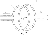
- the wireless power supply method mainly uses a magnetic coupling principle, as shown in FIG. 1, which can be implemented through a simple coil structure. That is, the induced current I2 is generated by the magnetic coupling generated by the mutual inductance (M) between the primary coil 1 corresponding to the power transmission stage and the secondary coil 2 corresponding to the power receiving stage. Power is supplied to the power receiving end by this induced current I2.
- M mutual inductance
- the magnitude of the induced current (I2) changes depending on the distance (O, misalignment) between the center of the primary coil 1 and the center of the secondary coil 2, the separation distance (d, separation) of both coils, According to the general principles of electromagnetism, these two distances get smaller as they get larger. This is because a magnetic field is formed around the primary coil 1 by the current I1 (sending current) applied from the power source to the primary coil 1, and the strength of the formed magnetic field decreases with distance. Therefore, the strength of the magnetic field formed around the primary coil 1 decreases as the two distances increase according to Ampere'slaw or Biot-Savart's law. The intensity of the magnetic field induced around the secondary coil 2 by mutual inductance from the magnetic field is also reduced, and the magnitude of the induced current I2 induced by the magnetic field induced around the secondary coil 2 is also reduced. .
- Such a conventional contactless charger only supplies power to a portable terminal (charger), and can not be used for other purposes, thereby limiting its practicality.
- the general contactless charger is limited to use because the transmission distance is short to transmit power wirelessly, it is an urgent task to develop a technology for transmitting to a wireless device at a distance.
- the problem to be solved by the present invention relates to a system and a method for providing a charging service to a mobile terminal remotely using a magnetic resonance induction method, using a magnetic field communication technology without the need for additional frequency band charger information
- the present invention proposes a method of performing an efficient charging service by recognizing this.
- Another problem to be solved by the present invention is to use a magnetic resonance induction method to enable remote long-range energy wireless charging, low frequency (LF) to satisfy a wide charge coverage, high charging efficiency and charging direction at the same time And high frequency (HF) are used together.
- LF low frequency
- HF high frequency
- Another problem to be solved by the present invention is to use a magnetic field communication technology of a plurality of chargers in order to be able to know the identification number of the corresponding device (ID), the battery status and the device distance and the like in the charging base station Based on this, we propose a method to perform efficient charging service through setting the priority of charging based on battery status, setting the charging band based on distance, and setting beamforming to increase the direction.
- ID identification number
- the charging base station we propose a method to perform efficient charging service through setting the priority of charging based on battery status, setting the charging band based on distance, and setting beamforming to increase the direction.
- Another object of the present invention to solve the problem is that when there is a foreign matter in the charging environment to interfere with the transfer of magnetic energy using the magnetic field communication in the charging base station to the presence of the foreign matter to the charging device, by adjusting the energy transmission power to provide an effective charging service Suggest ways to do it.
- Another problem to be solved by the present invention proposes a method of performing an efficient charging service by providing a service for the selective charging or simultaneous charging to a plurality of chargers using a Q-band conversion technique.
- Another problem to be solved by the present invention is to find a device capable of providing a charging service when the device that needs to be charged does not have a nearby charging base station. Suggest.
- the charging base station of the present invention transmits energy by matching the resonant frequency with the charger, and stores information about the charger requesting the charging with the communication unit including the coil and stores information for driving the charging base station. And a control unit controlling the communication unit to transfer energy to the charger requesting the charging.
- the charging system of the present invention requests charging to receive energy according to a magnetic resonance induction method, and stores information about a charger including a coil therein and the charger requesting charging, and the charger and the resonant frequency. It delivers energy by matching the, and includes a charging base station having a coil therein.
- the charging service method of the charger using the magnetic resonance induction method according to the present invention can provide an efficient charging service in consideration of charging distance, directionality, charging efficiency, etc. by using a low frequency and a high frequency band at the same time instead of a conventional single band system.
- the charging service method according to the present invention can prevent the additional frequency band loss by communicating with the magnetic field LF band at the same time as the charging service and at the same time can provide a service to a plurality of chargers.
- the present invention has the advantage of providing simultaneous charging service to multiple chargers using a Q band conversion technique and providing charging service between chargers without a charging base station.
- FIG. 2 is a diagram illustrating a process of wirelessly transferring energy between two resonant objects according to one embodiment of the present invention.
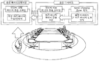
- FIG. 3 illustrates a charging area of a charging base station according to an embodiment of the present invention.
- FIG. 4 is a view illustrating an operation when a foreign material is present in a wireless charging environment according to an embodiment of the present invention.
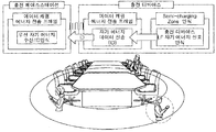
- FIG 5 is a view illustrating an operation when the position of the charger is changed by the movement of the user according to an embodiment of the present invention.
- FIG. 6 illustrates a case where another charger enters a quasi-charge region while performing charging according to an embodiment of the present invention.
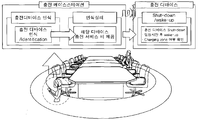
- FIG. 7 is a view illustrating an operation of identifying an identifier of a charging base station charger according to an embodiment of the present invention.
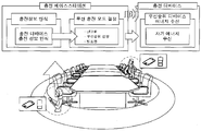
- FIG. 8 illustrates an operation of a charging base station when a plurality of chargers requests charging according to an embodiment of the present invention.
- FIG. 9 is a diagram illustrating a process of performing a charger period charging service according to an embodiment of the present invention.
- FIG. 2 is a diagram illustrating a process of wirelessly transferring energy between two resonant objects according to an embodiment of the present invention.
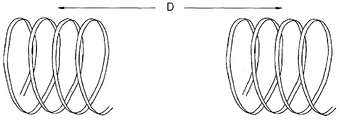
- energy is transferred between two magnetic resonance wire coils. Different resonant wire coils are interconnected by a magnetic field. Each self resonant wire coil uses the same resonant frequency to maximize energy transfer efficiency. That is, the conventional wireless energy transmission method using magnetic induction transmits energy using induced electromotive force induced by a magnetic field that changes with time. As described above, the wireless energy transmission method using magnetic induction can efficiently transmit power only at a close distance of several mm or less.
- the magnetic resonance induction method proposed in the present invention transmits energy using magnetic field resonance to increase charging distance and charging efficiency. That is, the magnetic field resonance occurs during the charging base station and the charger period, thereby increasing the charging efficiency.
- the charging terminal must enter the chargeable area of the charging base station in order to receive energy from the charging base station.
- the charging base station includes a control unit, a communication unit, and a storage unit.
- the communication unit communicates with the charger and includes a coil for energy transmission.
- the storage unit stores information for driving the charging base station and information about the chargers.
- the storage unit stores the identifier for the charger requesting the charging and information on whether the charger is charged.
- the control unit controls the communication unit and the storage unit constituting the charging base station, and controls a series of operations performed in the charging base station mentioned below.
- FIG. 3 illustrates a charging area of a charging base station according to an embodiment of the present invention.
- the charging area of the charging base station will be described with reference to FIG. 3.
- the charging area of the charging base station is divided into a charging zone and a semi-charging zone.
- the charging area is an area where direct charging from the charging base station 100 to the charger 200 is performed
- the semi-charging area is an area where pre-step operations for performing charging are performed. That is, the quasi-charge area is an area in which it is possible to identify whether or not charge is possible by performing previous steps for performing charging. 3 shows the charging area shown in yellow and the quasi-charge area shown in blue.
- the charger 200 When the charger 200 enters the quasi-charge region of the charging base station 100, the charger 200 transmits a join request packet to the charging base station 100. Receiving the join request packet from the charger 200, the charging base station 100 determines whether to allow or reject the join. When the charger 200 receives the join permission packet allowing the joining from the charging base station 100, the charger 200 performs a series of procedures for receiving the charging from the charging base station 100. The charger 200 does not receive the join permission packet allowing the join from the charging base station 200, or if an error occurs in the received join allow packet, the charger 200 retransmits the join request packet to the charging base station 100. .
- the charger 200 transmits a join request packet including its identifier (ID) to the charging base station 100 using the LF band, and the charging base station 100 It is determined whether the join permission packet is transmitted using the received ID.
- ID its identifier
- Packets allowed to join then receive energy from the charging base station 100 using their identifiers. That is, when the charger 200 entering the quasi-charging region enters the charging region, it receives energy from the charging base station 100 using its identifier.
- the charging base station 100 transfers energy to the charger using a magnetic resonance induction method. To this end, the charging base station 100 and the charger 200 transmit and receive information on the resonant frequency to each other to match the resonant frequency to efficiently perform the charging.
- the frequency used for packet transmission and reception performed between the charger 200 and the charging base station 100 uses the same frequency as the frequency used for charging.
- the frequency used for energy transmission between the charger 200 and the charging base station 100 is a low frequency
- the packet transmitted and received between the charger 200 and the charging base station 100 also uses a low frequency so that an additional frequency is unnecessary. Done.
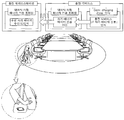
- FIG. 4 is a diagram illustrating an operation when there is a foreign matter (interference material) in the wireless charging environment according to an embodiment of the present invention.
- a foreign matter interference material
- the charging base station when there is a foreign matter in the wireless charging environment that interferes with the transfer of magnetic energy, the charging base station notifies the charger of the presence of the foreign matter.
- the charging base station notifying the presence of foreign matter, regulates the energy transfer power to ensure efficient energy transfer. That is, when the charging base station recognizes that the foreign matter is present in the wireless charging environment, the charging base station transmits information about it to the charger and simultaneously adjusts the energy transmission power automatically.
- an object made of a foreign material metallic material that interferes with the transfer of magnetic energy is included. If there is a foreign object in the wireless charging environment that interferes with the transfer of magnetic energy, the base station detects a change in the magnetic field caused by the foreign material and recognizes the presence of the foreign material. 4 illustrates various foreign matters that interfere with various energy transmissions related to the present invention.
- the charging base station when the charging base station detects a foreign material, the charging base station provides information about it.
- the charger displays the received information on the display unit or outputs it using a speaker.
- the charger user uses the output information to remove foreign objects that interfere with energy transmission.
- FIG. 5 is a view illustrating an operation when the position of the charger is changed by the movement of the user according to an embodiment of the present invention.
- the operation in the case where the position of the charger is changed by the movement of the user will be described in detail with reference to FIG. 5.
- the charging base station tracks the position of the charger in a certain time or real time using a location tracking algorithm.
- the charging base station determines the distance through communication with the charger and performs a peripheral scan using a three-axis (3D) antenna to match the antenna with the most efficient charger.
- the charging base station uses a location tracking algorithm to recognize the location of the changed charger.
- the charging base station selects one of the LF mode, the HF mode, and the dual mode so as to perform optimal charging when the position of the charger is changed, and performs charging using the selected mode.
- the LF mode transmits energy to a charger located at a remote location with low transmission efficiency
- the HF mode delivers energy to a charger located at a short distance with high transmission efficiency.
- the charging base station transmits energy in a mode capable of performing optimal charging according to the distance of the charger.
- the charging base station improves charging efficiency through 3D beamforming when the charger is located in the shaded area.
- 3D beamforming transfers the magnetic energy from the triaxial antenna of the charging base station to the energy focus using resonance when the position of the charger is not confirmed.
- a plurality of antennas receive magnetic energy by using resonance as energy, and two antennas receive precoded signals simultaneously and perform beamforming.
- the charging base station performs a peripheral scan operation using the 3D antenna to determine the most efficient antenna and transmits energy to the charger using the antenna.
- FIG. 6 illustrates a case where another charger enters a quasi-charge region while performing charging according to an embodiment of the present invention.
- another charger entering the quasi-charge region transmits a join request packet including its identifier to the charging base station.
- the charging base station recognizes another charger entering the quasi-charge area through the reception of the join request packet. Since the operation performed in the charging base station is the same as FIG.
- the charging base station recognizes the identifier of the charger requesting the charging.
- the charging base station shuts down the charger so that the charging service of the charger is not provided. That is, the charging base station shuts down between the charging board of the charger and the antenna coil when the charger is not certified.
- the shut down charger switches to a wake-up state after a certain period of time and reconfirms whether the charger is in the charging region.
- the charger retransmits the charge request message including its identifier to the charging base station in the charging area.
- the charging base station stores the information about the charger requesting the charging and the charger which has transmitted the actual energy and the charger which has failed to transmit energy.
- the charging base station may separately store and manage information about a charger whose identifier is not recognized.
- the charging base station may store information about the charger that has actually performed the charging and the charging amount of the charger, the charger that has not been charged, and the uncharged cause of the charger.
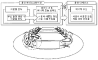
- FIG. 8 illustrates an operation of a charging base station when a plurality of chargers requests charging according to an embodiment of the present invention.
- the charging base station when a plurality of chargers request charging, the charging base station performs a charging service according to priority.
- the priority may be listed according to the battery level of the charger requesting charging, the distance from the charging base station, and the like. That is, the charging base station first transmits energy to a charger located far from the charging base station, and finally delivers energy to a charger located close to the charging base station.
- the charging base station performs charging in order of higher priority chargers when a plurality of chargers request charging.
- the charging base station may perform a charging service for all chargers requesting charging.
- the charging base station widens the Q band even though the transmission rate is low so as to perform the charging service for the plurality of chargers, thereby enabling charging even if the resonant frequencies do not match.
- the Q band By widening the Q band in this way, a plurality of chargers can receive energy simultaneously. In other words, the wider the Q band, the greater the number of chargers capable of receiving energy from the charging base station. Therefore, it is possible to select a charger to provide a charging service by adjusting the width of the Q band.
- the width of the Q band is adjusted using the R, L, and C parameters.
- FIG. 9 is a diagram illustrating a process of performing a charger period charging service according to an embodiment of the present invention.
- a process of performing another charger period charging service according to an embodiment of the present invention will be described with reference to FIG. 9.
- the charger in order to receive energy from the charging base station, the charger must enter the charging area of the charging base station and search for the charging base station. However, when the charger fails to enter the charging area of the charging base station, or enters the charging area of the charging base station, the charging base station cannot be found. In this case, the charger may receive energy from an adjacent charger. That is, the charger searches for a charger capable of transmitting energy among adjacent chargers. The charger transmits an energy transfer request packet including its identifier to a charger capable of transmitting energy. The charger capable of transmitting energy determines whether to approve the energy transmission by analyzing the information included in the received energy transmission request packet. In this case, a charger capable of transmitting energy may determine whether to approve energy transmission by referring to its battery capacity. As such, the charger of the present invention receives energy from an adjacent charger as well as a charging base station to perform charging.
Landscapes
- Engineering & Computer Science (AREA)
- Computer Networks & Wireless Communication (AREA)
- Power Engineering (AREA)
- Manufacturing & Machinery (AREA)
- Chemical & Material Sciences (AREA)
- Chemical Kinetics & Catalysis (AREA)
- Electrochemistry (AREA)
- General Chemical & Material Sciences (AREA)
- Signal Processing (AREA)
- Charge And Discharge Circuits For Batteries Or The Like (AREA)
Abstract
본 발명은 자기공진유도 방식을 이용하여 다수의 충전기기들에게 무선으로 충전 서비스를 제공하는 방법에 관한 것으로, 더욱 상세하게는 자기장 통신 기술을 이용하여 추가적인 주파수 밴드의 소모없이 충전기기들의 정보를 인식하여 효율적인 충전 서비스가 가능하도록 하는 충전 방법에 관한 것이다. 이를 위해 본 발명의 충전 시스템은 자기공진유도 방식에 따라 에너지를 제공받기 위해 충전을 요청하며, 내부에 코일을 포함하고 있는 충전기기와 충전을 요청한 상기 충전기기에 대한 정보를 저장하며, 상기 충전기기와 공진 주파수를 일치시켜 에너지를 전달하며, 내부에 코일을 포함하고 있는 충전 베이스 스테이션을 포함한다.
Description
본 발명은 자기공진유도 방식을 이용하여 다수의 충전기기들에게 무선으로 충전 서비스를 제공하는 방법에 관한 것으로, 더욱 상세하게는 자기장 통신 기술을 이용하여 추가적인 주파수 밴드의 소모없이 충전기기들의 정보를 인식하여 효율적인 충전 서비스가 가능하도록 하는 충전 방법에 관한 것이다.
일반적으로 휴대폰, PDA, PMP, DMB 단말기, MP3 또는 노트북과 같은 휴대 단말들은 일반 가정 전원을 이용할 수 없어 일회용 배터리를 장착하거나 충방전이 가능한 배터리가 장착된다. 그리고 이러한 휴대 단말의 배터리에 전기를 충전시키기 위한 충전기는 일반전원으로부터 전기를 공급받아 배터리터리에 전원공급단자를 통하여 배터리팩에 전원을 공급하는 단자공급방식이 이용되고 있다. 하지만 이러한 단자공급방식으로 전원을 공급하면, 충전기와 배터리가 서로 결합되거나 분리될 경우, 양측의 단자들이 서로 다른 전위차를 가지고 있어서 순간방전현상이 발생된다. 이로써 양측 단자들에는 점점 이물질이 쌓이게 되며, 이로 인해서 화재가 발생할 우려가 있는 것이다. 또한 습기가 묻어 자연 방전되는 등 충전기 및 배터리의 수명 및 성능을 저하시키는 문제점이 있다.
이와 같은 단자공급방식의 문제점을 해결하기 위하여, 무접점 충전기가 개발되었다. 이러한 종래기술에 따른 무접점 충전기는 무접점충전기의 1차코일의 상부로, 충전하고자 하는 배터리가 내재된 단말기를 위치시키면, 배터리의 2차코일에 의하여 충전이 된다. 즉 1차코일에서 발생되는 자기장에 의해 2차코일에서는 유도기전력으로 유도되는 전기를 충전하는 것이다.
부가하여 설명하면, 무선 전력의 공급 방식은 주로 자기 결합 원리를 이용하는데, 도 1에 제시된 바와 같이, 간단한 코일(coil) 구조를 통해 구현할 수 있다. 즉, 송전단에 해당하는 1차 코일(1)과 수전단에 해당하는 2차 코일(2)간 상호 인덕턴스(Mutual inductance, M)로 인해 발생하는 자기 결합에 의해 유도 전류(I2)가 발생되며, 이 유도전류(I2)에 의해 수전단에 전력이 공급된다.
이때 유도 전류(I2)의 크기는 1차 코일(1)의 중심부와 2차 코일(2)의 중심부와의 거리(O, misalignment), 양 코일의 분리 간격(d, separation)에 따라 변화하는데, 전자기학의 일반원칙에 따르면 이들 두 거리가 커질수록 작아진다. 왜냐하면 전원 소스로부터 1차 코일(1)에 인가되는 전류(I1, 송출 전류)에 의해 1차 코일(1) 주변에 자기장이 형성되고, 형성되는 자기장의 세기는 거리에 따라 감소하기 때문이다. 따라서 앙페르의 법칙(Ampere'slaw) 내지는 비오-사바르의 법칙(Biot-Savart's law)에 의해 상기 두 거리가 커질수록 1차 코일(1) 주변에 형성되는 자기장의 세기는 감소하며, 이렇게 형성되는 자기장으로부터 상호 인덕턴스에 의해 2차 코일(2) 주변에 유도되는 자기장의 세기도 감소하며, 2차 코일(2) 주변에 유도되는 자기장에 의해 유도되는 유도 전류(I2)의 크기도 작아지는 것이다.
그러나 이러한 종래의 무접점 충전기는 단지 휴대 단말(충전기기)에 전력을 공급할 뿐, 다른 용도로 이용할 수 없어 실용성에 제한이 있는 것이다. 또한 일반적인 무접점 충전기는 무선으로 전력을 전송하기에 전송거리가 짧아 이용에 제한이 되고 있어 이격된 거리의 무선기기에 전송하기 위한 기술 개발이 시급한 과제이다.
본 발명이 해결하려는 과제는 자기공진유도 방식을 이용하여 휴대 단말에 원격으로 충전 서비스를 제공할 수 있도록 하는 시스템 및 방법에 관한 것으로, 자기장 통신 기술을 이용하여 추가적인 주파수 밴드의 소모없이 충전기기들의 정보를 인식하여 효율적인 충전 서비스를 수행하는 방안을 제안한다.
본 발명이 해결하려는 다른 과제는 원격으로 중거리 에너지 무선 충전이 가능할 수 있도록 자기공진유도 방식을 사용하며, 넓은 충전 커버리지, 높은 충전 효율 및 충전 방향성 등을 동시에 만족시킬 수 있도록 저주파 (low frequency, LF) 및 고주파 (high frequency ,HF)를 같이 사용한다. 두 개의 밴드의 선택적 사용, 동시 사용 등의 서비스 모드를 가지고 보다 효율적인 충전 서비스를 수행하는 방안을 제안한다.
본 발명이 해결하려는 또 다른 과제는 다수의 충전기기들을 LF 대역의 자기장 통신 기술을 이용하여 해당 기기들의 고유번호 (ID) 인식, 배터리 상태 및 기기 거리 등을 정보를 충전 베이스 스테이션에서 알 수 있게 하고, 이를 기반으로 배터리 상태 기반의 충전 우선순위 설정, 거리 기반의 충전 밴드 설정, 방향성을 높일 수 있는 빔포밍 설정 등으로 통해서 효율적인 충전 서비스를 수행하는 방안을 제안한다.
본 발명이 해결하려는 또 다른 과제는 자기장 통신을 이용하여 충전 환경내에 자기 에너지 전달에 방해가 되는 이물질이 있을 경우 충전 베이스 스테이션에서 충전 디바이스에 이물질 존재를 알려, 에너지 전송 파워를 조절하여 효과적인 충전 서비스를 수행하는 방안을 제안한다.
본 발명이 해결하려는 또 다른 과제는 Q밴드 변환 기법을 이용하여 다수의 충전기기들에게 선택적 충전 혹은 동시 충전을 할 수 있도록 서비스를 제공하여 효율적인 충전 서비스를 수행하는 방안을 제안한다.
본 발명이 해결하려는 또 다른 과제는 충전이 필요한 기기가 주변에 충전 베이스 스테이션이 없을 경우, 주변에 충전 서비스 제공이 가능한 기기를 찾아 충전 서비스를 요청하여 충전기기 간의 에너지 전송을 제공할 수 있는 방안을 제안한다.
이를 위해 본 발명의 충전 베이스 스테이션은 상기 충전기기와 공진 주파수를 일치시켜 에너지를 전달하며, 코일을 포함하고 있는 통신부와 충전을 요청한 충전기기에 대한 정보 및 상기 충전 베이스 스테이션의 구동을 위한 정보를 저장하는 저장부와 상기 충전을 요청한 충전기기에 대해 에너지 전달하도록 상기 통신부를 제어하는 제어부를 포함한다.
이를 위해 본 발명의 충전 시스템은 자기공진유도 방식에 따라 에너지를 제공받기 위해 충전을 요청하며, 내부에 코일을 포함하고 있는 충전기기와 충전을 요청한 상기 충전기기에 대한 정보를 저장하며, 상기 충전기기와 공진 주파수를 일치시켜 에너지를 전달하며, 내부에 코일을 포함하고 있는 충전 베이스 스테이션을 포함한다.
본 발명에 따른 자기공진유도 방식을 이용한 충전기기의 충전 서비스 방법은 기존의 싱글 밴드 시스템이 아닌 저주파 및 고주파 밴드를 동시에 사용하여 충전거리, 방향성, 충전 효율 등을 고려하여 효율적인 충전 서비스를 제공할 수 있게 한다. 또한 본 발명에 따른 충전 서비스 방법은 충전 서비스와 동시에 자기장 LF 밴드를 이용한 통신을 함으로써 추가적인 주파수 밴드 손실을 막을 수 있음과 동시에 다수의 충전기기들에게 서비스를 제공할 수 있게 한다. 부가하여 본 발명은 Q 밴드 변환 기법을 이용하여 여러 충전기기들에게 동시 충전 서비스를 제공하며, 충전 베이스 스테이션 없이도 충전기기들 간의 충전 서비스를 제공할 수 있게 한다는 장점을 가지게 된다.
도 1은 자기 결합 원리를 이용한 무선 전력 공급 방식을 도시하고 있으며,
도 2는 본 발명의 일실시 예에 따른 두 개의 공진 물체 사이를 에너지가 무선으로 전달되는 과정을 도시한 도면이며,
도 3은 본 발명의 일실시 예에 따른 충전 베이스 스테이션의 충전 영역을 도시하고 있으며,
도 4는 본 발명의 일실시 예에 따른 무선 충전 환경 내에 이물질이 있는 경우의 동작을 도시하고 있으며,
도 5는 본 발명의 일실시 예에 따른 사용자의 이동으로 충전기기의 위치가 변동되는 경우의 동작을 도시하고 있으며,
도 6은 본 발명의 일실시 예에 따른 충전 수행 중 다른 충전기기가 준-충전영역으로 진입하는 경우를 도시하고 있으며,
도 7은 본 발명의 일실시 예에 따른 충전 베이스 스테이션 충전기기의 식별자 인식에 따른 동작을 도시하고 있으며,
도 8은 본 발명의 일실시 예에 따른 복수의 충전기기가 충전을 요청한 경우 충전 베이스 스테이션의 동작을 도시하고 있으며,
도 9는 본 발명의 일실시 예에 따른 충전기기간 충전 서비스를 수행하는 과정을 도시한 도면이다.
전술한, 그리고 추가적인 본 발명의 양상들은 첨부된 도면을 참조하여 설명되는 바람직한 실시 예들을 통하여 더욱 명백해질 것이다. 이하에서는 본 발명의 이러한 실시 예를 통해 당업자가 용이하게 이해하고 재현할 수 있도록 상세히 설명하기로 한다.
도 2는 본 발명의 일실시 예에 따른 두 개의 공진 물체 사이를 에너지가 무선으로 전달되는 과정을 도시한 도면이다. 도 2를 참조하면, 두 개의 자기 공진 와이어 코일간에 에너지가 전달된다. 서로 다른 공진 와이어 코일은 자기장으로 상호 연결된다. 각 자기 공진 와이어 코일은 동일한 공진 주파수를 사용함으로써 에너지 전송 효율을 극대화한다. 즉 종래 자기 유도를 이용한 무선 에너지 전송방법은 시간에 따라 변하는 자기장이 유도하는 유도 기전력을 이용하여 에너지를 전송한다. 상술한 바와 같이 자기 유도를 이용한 무선 에너지 전송 방법은 수mm 이하의 가까운 거리에서만 효율적인 전력 전송이 가능하다.
하지만, 본 발명에서 제안하는 자기공진유도 방식은 충전거리와 충전효율을 높이기 위해 자기장 공진을 이용하여 에너지를 전송한다. 즉, 충전 베이스 스테이션과 충전기기간에 자기장 공진을 일으켜서 충전 효율을 높이게 된다.
이하에서는 충전 단말과 충전 단말로 에너지를 전달하는 충전 베이스 스테이션간에 수행되는 동작에 대해 알아보기로 한다. 충전 단말은 충전 베이스 스테이션으로부터 에너지를 전달받기 위해서는 충전 베이스 스테이션의 충전 가능 영역으로 진입해야 한다.
본 발명과 관련하여 충전 베이스 스테이션은 제어부와 통신부, 저장부를 포함한다. 통신부는 충전기기와의 통신을 수행하며, 에너지 전송을 위한 코일을 포함한다.
저장부는 충전 베이스 스테이션을 구동하기 위한 정보와 충전기기들에 대한 정보가 저장된다. 저장부는 충전을 요청한 충전기기에 대한 식별자 및 충전 여부에 대한 정보가 저장된다. 제어부는 충전 베이스 스테이션을 구성하고 있는 통신부와 저장부를 제어하며, 하기에서 언급하고 있는 충전 베이스 스테이션에서 수행되는 일련의 동작들을 제어한다.
도 3은 본 발명의 일실시 예에 따른 충전 베이스 스테이션의 충전 영역을 도시하고 있다. 이하 도 3을 이용하여 충전 베이스 스테이션의 충전 영역에 대해 알아보기로 한다.
도 3에 의하면, 충전 베이스 스테이션의 충전 영역은 충전 영역(charging zone)과 준-충전 영역(semi-charging zone)으로 구분된다. 충전 영역은 충전 베이스 스테이션(100)에서 충전기기(200)로 직접적인 충전이 이루어지는 영역이며, 준-충전 영역은 충전을 수행하기 위한 전 단계 동작들이 수행되는 영역이다. 즉, 준-충전 영역은 충전을 수행하기 위한 전 단계 동작들의 수행함으로써 충전 가능 여부를 식별할 수 있는 영역이다. 도 3은 노란색으로 표시된 충전 영역과 파란색으로 표시된 준-충전 영역을 나타내고 있다.
충전기기(200)가 충전 베이스 스테이션(100)의 준-충전 영역으로 진입하면, 충전기기(200)는 충전 베이스 스테이션(100)으로 합류 요청 패킷을 전송한다. 충전기기(200)로부터 합류 요청 패킷을 수신한 충전 베이스 스테이션(100)은 합류를 허용할 지 거절할지 여부를 결정한다. 충전기기(200)는 충전 베이스 스테이션(100)으로부터 합류를 허용하는 합류 허용 패킷을 수신하면 충전 베이스 스테이션(100)으로부터 충전을 받기 위한 일련의 과정들을 수행한다. 충전기기(200)는 충전 베이스 스테이션(200)으로부터 합류를 허용하는 합류 허용 패킷을 수신하지 못하거나, 수신된 합류 허용 패킷에 오류가 발생한 경우에는 합류 요청 패킷을 충전 베이스 스테이션(100)으로 재송신한다.
즉, 충전기기(200)는 준-충전영역으로 진입하면 LF 대역을 이용하여 자신의 식별자(ID)가 포함된 합류 요청 패킷을 충전 베이스 스테이션(100)으로 전송하고, 충전 베이스 스테이션(100)은 수신된 ID를 이용하여 합류 허용 패킷의 전송 여부를 판단한다.
합류가 허용된 패킷은 이후 자신의 식별자를 이용하여 충전 베이스 스테이션(100)으로부터 에너지를 전달받는다. 즉, 준-충전영역에 진입한 충전기기(200)가 충전영역으로 진입하게 되면, 자신의 식별자를 이용하여 충전 베이스 스테이션(100)으로부터 에너지를 전달받게 된다. 충전 베이스 스테이션(100)은 자기공진 유도 방식을 이용하여 충전기기로 에너지를 전달한다. 이를 위해 충전 베이스 스테이션(100)과 충전기기(200)는 상호간에 공진 주파수에 대한 정보를 송수신하여 공진 주파수를 일치시켜 효율적으로 충전을 수행할 수 있도록 한다.
본 발명과 관련하여 충전기기(200)와 충전 베이스 스테이션(100)간의 수행되는 패킷 송수신에 사용되는 주파수는 충전에 사용되는 주파수와 동일한 주파수를 사용한다. 일예로 충전기기(200)와 충전 베이스 스테이션(100)간에 에너지 전송에 사용되는 주파수가 저주파인 경우 충전기기(200)와 충전 베이스 스테이션(100)간에 송수신되는 패킷 역시 저주파를 이용함으로써 추가적인 주파수를 불필요하게 된다.
도 4는 본 발명의 일실시 예에 따른 무선 충전 환경 내에 이물질(방해물질)이 있는 경우의 동작을 도시하고 있다. 이하 도 4를 이용하여 본 발명의 일실시 예에 따른 무선 충전 환경 내에 이물질이 있는 경우의 동작에 대해 알아보기로 한다.
도 4에 의하면, 무선 충전 환경 내에 자기 에너지 전달에 방해가 되는 이물질이 있는 경우 충전 베이스 스테이션은 충전기기로 이물질의 존재를 통보한다. 이물질의 존재를 통보한 충전 베이스 스테이션은 에너지 전송 파워를 조절하여 효율적인 에너지 전송이 이루어지도록 한다. 즉, 충전 베이스 스테이션은 무선 충전 환경 내에 이물질이 존재하고 있음을 인식하게 되면, 충전기기로 이에 대한 정보를 전송하며 동시에 자동으로 에너지 전송 파워를 조절한다. 본 발명과 관련하여 자기 에너지 전달에 방해가 되는 이물질 금속재질의 물건이 포함된다. 베이스 스테이션은 무선 충전 환경 내에 자기 에너지 전달에 방해가 되는 이물질이 있는 경우, 이물질에 의한 자기장의 변화를 감지하여 이물질의 존재를 인식하게 된다. 도 4는 본 발명과 관련된 다양한 에너지 전송에 방해가 되는 다양한 이물질을 도시하고 있다.
본 발명과 관련하여 충전 베이스 스테이션은 이물질을 감지한 경우, 충전기기로 이에 대한 정보를 제공한다. 충전기기는 제공받은 정보를 표시부에 표시하거나, 스피커를 이용하여 출력한다. 충전기기 사용자는 출력된 정보를 이용하여 에너지 전송에 방해가 되는 이물질을 제거한다.
도 5는 본 발명의 일실시 예에 따른 사용자의 이동으로 충전기기의 위치가 변경되는 경우의 동작을 도시하고 있다. 이하 도 5를 이용하여 사용자의 이동으로 충전기기의 위치가 변경되는 경우의 동작에 대해 상세하게 알아보기로 한다.
도 5에 의하면, 충전 베이스 스테이션은 위치 추적 알고리즘을 이용하여 충전기기의 위치를 일정시간 또는 실시간으로 추적한다. 본 발명과 관련하여 충전 베이스 스테이션은 충전기기와의 통신을 통해 거리를 파악한 후 3축(3D) 안테나를 이용하여 주변 스캔 작업을 수행하여 가장 효율이 높은 안테나와 충전기기를 매칭시킨다.
충전 베이스 스테이션은 위치 추적 알고리즘을 이용하여 변경된 충전기기의 위치를 인지한다. 충전 베이스 스테이션은 충전기기의 위치가 변경되면 최적의 충전을 수행할 수 있도록 LF 모드, HF 모드, 듀얼 모드 중 하나의 모드를 선택하고, 선택된 모드를 이용하여 충전을 수행한다. LF 모드는 전송 효율은 낮으나 원거리에 위치하고 있는 충전기기로 에너지를 전달할 수 있으며, HF 모드는 전송 효율은 높고 근거리에 위치하고 있는 충전기기로 에너지를 전달할 수 있다. 따라서 충전 베이스 스테이션은 충전기기의 거리에 따라 최적의 충전을 수행할 수 있는 모드로 에너지를 전송한다. 충전 베이스 스테이션은 충전기기가 음영지역에 위치하고 있는 경우에는 3D 빔포밍을 통해 충전 효율을 높인다. 3D 빔포밍은 충전기기의 위치가 확인되지 않은 경우에 충전 베이스 스테이션의 3축 안테나에서 나오는 자기 에너지를 공진을 이용하여 에너지 집속형(Energy Focus)으로 전달한다. 예를 들어 통신에서 두개의 안테나가 동시에 프리코딩된 신호를 받아서 빔포밍을 수행하는 것과 동일하게 복수의 안테나가 자기 에너지를 공진을 이용하여 에너지를 집속적으로 전달받는다.
물론 충전기기의 위치가 확인되는 경우에는 상술한 바와 같이 충전 베이스 스테이션은 3D 안테나를 이용하여 주변 스캔 작업을 수행하여 가장 효율이 높은 안테나를 결정하고, 해당 안테나를 이용하여 충전기기로 에너지를 전송한다.
도 6은 본 발명의 일실시 예에 따른 충전 수행 중 다른 충전기기가 준-충전영역으로 진입하는 경우를 도시하고 있다. 도 6에 의하면 준-충전영역에 진입한 다른 충전기기는 자신의 식별자가 포함된 합류 요청 패킷을 충전 베이스 스테이션으로 전송한다. 충전 베이스 스테이션은 합류 요청 패킷의 수신을 통해 준-충전영역으로 진입한 다른 충전기기를 인식하게 된다. 이후 충전 베이스 스테이션에서 수행되는 동작은 도 3과 동일하다.
도 7은 본 발명의 일실시 예에 따른 충전 베이스 스테이션 충전기기의 식별자 인식에 따른 동작을 도시하고 있다. 도 7에 의하면, 충전 베이스 스테이션은 충전을 요청한 충전기기의 식별자를 인식한다. 충전 베이스 스테이션은 충전을 요청한 충전기기의 식별자를 인식하지 못한 경우 해당 충전기기의 충전 서비스가 제공되지 않도록 충전기기를 셔트-다운(shut-down, 차단)시킨다. 즉, 충전 베이스 스테이션은 충전기기 미인증시 충전기기의 충전 보드와 안테나 코일 사이를 셔트 다운시킨다. 셔트 다운된 충전기기는 일정 시간 경과 후 웨이크-업(wake-up) 상태로 전환되어 충전 영역인지 여부를 재확인한다. 충전기기는 충전 영역인 경우 충전 베이스 스테이션으로 자신의 식별자가 포함된 충전 요청 메시지를 재전송한다.
충전 베이스 스테이션은 충전을 요청한 충전기기에 대한 정보 및 실제 에너지를 전송한 충전기기 및 에너지 전송에 실패한 충전기기에 대한 정보를 저장한다. 충전 베이스 스테이션은 식별자가 인식되지 않는 충전기기에 대한 정보는 별도로 저장 및 관리할 수 있다. 또한, 과금과 관련하여 충전 베이스 스테이션은 실제 충전을 수행한 충전기기 및 해당 충전기기의 충전 금액, 충전이 수행되지 않은 충전기기 및 해당 충전기기의 미충전 원인에 대한 정보를 저장할 수 있다.
도 8은 본 발명의 일실시 예에 따른 복수의 충전기기가 충전을 요청한 경우 충전 베이스 스테이션의 동작을 도시하고 있다. 도 8에 의하면 복수의 충전기기가 충전을 요청한 경우, 충전 베이스 스테이션은 우선순위에 따라 충전 서비스를 수행한다. 우선순위는 충전을 요청한 충전기기의 배터리 잔량, 충전 베이스 스테이션과의 거리 등에 따라 나열될 수 있다. 즉, 충전 베이스 스테이션은 충전 베이스 스테이션으로부터 먼거리에 위치하고 있는 충전기기에 대해 먼저 에너지를 전달하며, 충전 베이스 스테이션으로부터 가까운 거리에 위치하고 있는 충전기기에 대해서는 마지막으로 에너지를 전달할 수 있다.
충전 베이스 스테이션은 복수의 충전기기가 충전을 요청하면 우선순위가 높은 충전기기 순으로 충전을 수행한다. 물론 충전 베이스 스테이션은 복수의 충전기기가 충전을 요청하면, 충전을 요청한 모든 충전기기들에 대해 충전 서비스를 수행할 수 있다. 충전 베이스 스테이션은 복수의 충전기기들에 대해 충전 서비스를 수행하기 위해 전송율은 낮더라도 Q 밴드를 와이드(wide)하게 하여 공진주파수가 일치하지 않더라도 충전이 가능하게 한다. 이와 같이 Q밴드를 와이드하게 함으로써 복수의 충전기기들이 동시에 에너지를 전달받을 수 있다. 즉, Q 밴드의 폭이 넓을수록 충전 베이스 스테이션으로부터 에너지를 전달받을 수 있는 충전기기의 수 역시 증가한다. 따라서 Q 밴드의 폭을 조절하여 충전 서비스를 제공할 충전기기를 선택할 수 있게 된다. Q 밴드의 폭은 R, L, C 파라미터를 이용하여 조절한다.
도 9는 본 발명의 일실시 예에 따른 충전기기간 충전 서비스를 수행하는 과정을 도시한 도면이다. 이하 도 9를 이용하여 본 발명의 일실시 예에 다른 충전기기간 충전 서비스를 수행하는 과정에 대해 알아보기로 한다.
상술한 바와 같이 충전기기가 충전 베이스 스테이션으로부터 에너지를 전달받기 위해서는 충전 베이스 스테이션의 충전 영역으로 진입하여 충전 베이스 스테이션을 탐색하여야 한다. 하지만 충전기기가 충전 베이스 스테이션의 충전 영역으로 진입하지 못한 경우, 또는 충전 베이스 스테이션의 충전 영역으로 진입하였으나 충전 베이스 스테이션을 탐색하지 못하는 경우가 발생한다. 이 경우 충전기기는 인접한 충전기기로부터 에너지를 전달받을 수 있다. 즉, 충전기기는 인접 충전기기들 중 에너지 전송이 가능한 충전기기를 탐색한다. 충전기기는 에너지 전송이 가능한 충전기기로 자신의 식별자 포함된 에너지 전송 요청 패킷을 전송한다. 에너지 전송이 가능한 충전기기는 전송받은 에너지 전송 요청 패킷에 포함되어 있는 정보를 분석하여 에너지 전송을 승인할 지 여부를 결정한다. 이 경우 에너지 전송이 가능한 충전기기는 자신의 배터리 용량을 참고하여 에너지 전송을 승인할 지 여부를 결정한다. 이와 같이 본 발명의 충전기기는 충전 베이스 스테이션뿐만 아니라 인접 충전기기로부터 에너지를 전달받아 충전을 수행한다.
본 발명은 도면에 도시된 일실시 예를 참고로 설명되었으나, 이는 예시적인 것에 불과하며, 본 기술분야의 통상의 지식을 가진 자라면 이로부터 다양한 변형 및 균등한 타 실시예가 가능하다는 점을 이해할 것이다.
Claims (13)
- 충전을 요청한 충전기기로 에너지를 전달하는 충전 베이스 스테이션에 있어서,상기 충전기기와 공진 주파수를 일치시켜 에너지를 전달하며, 코일을 포함하고 있는 통신부;충전을 요청한 충전기기에 대한 정보 및 상기 충전 베이스 스테이션의 구동을 위한 정보를 저장하는 저장부;상기 충전을 요청한 충전기기에 대해 에너지 전달하도록 상기 통신부를 제어하는 제어부를 포함함을 특징으로 하는 충전 베이스 스테이션.
- 제 1항에 있어서,상기 충전 베이스 스테이션은 충전을 위한 충전기기의 식별자를 인식하는 준-충전 영역과 상기 식별자를 인식한 충전기기에 대해 에너지를 전달하는 충전 영역을 형성함을 특징으로 충전 베이스 스테이션.
- 제 2항에 있어서,정보 전송을 위해 상기 준-충전영역에서 상기 충전 베이스 스테이션과 상기 충전기기간에 송수신되는 주파수 밴드와 상기 에너지 전달을 위해 상기 충전영역에서 상기 충전 베이스 스테이션로부터 상기 충전기기로 전달되는 주파수 밴드는 동일함을 특징으로 하는 충전 베이스 스테이션.
- 제 2항에 있어서, 상기 제어부는,상기 충전기기의 위치의 위치에 따라 저주파(LF) 통신 모드, 고주파(HF) 통신 모드 및 듀얼 통신 모드 중 하나를 이용하여 에너지를 전송하도록 지시함을 특징으로 하는 충전 베이스 스테이션.
- 제 2항에 있어서, 상기 제어부는,에너지 전송에 방해가 되는 방해 물질이 상기 충전 영역에 존재하는 여부를 실시간으로 감시함을 특징으로 하는 충전 베이스 스테이션.
- 제 2항에 있어서, 상기 제어부는,충전을 요청한 상기 충전기기의 위치를 인식되기 않으면 X축 안테나, Y축 안테나, Z축 안테나로 상기 에너지를 전송하도록 지시함을 특징으로 하는 충전 베이스 스테이션.
- 제 2항에 있어서, 상기 제어부는,충전을 요청한 상기 충전기기의 식별자가 인식되지 않으면 상기 충전기기의 충전 회로를 차단하도록 지시함을 특징으로 하는 충전 베이스 스테이션.
- 제 2항에 있어서, 상기 제어부는,복수의 충전기기로부터 충전이 요청되면, 충전 우선순위에 따라 충전을 수행하도록 지시함을 특징으로 하는 충전 베이스 스테이션.
- 자기공진유도 방식에 따라 에너지를 제공받기 위해 충전을 요청하며, 내부에 코일을 포함하고 있는 충전기기;충전을 요청한 상기 충전기기에 대한 정보를 저장하며, 상기 충전기기와 공진 주파수를 일치시켜 에너지를 전달하며, 내부에 코일을 포함하고 있는 충전 베이스 스테이션을 포함하는 충전 시스템.
- 제 9항에 있어서, 상기 충전기기와 충전 베이스 스테이션은 공진 주파수를 일치시키기 위해 공진 주파수에 대한 정보를 송수신함을 특징으로 하는 충전 시스템.
- 제 9항에 있어서, 상기 충전 베이스 스테이션은,복수의 충전기기로부터 충전이 요청되면, R, L, C 파라미터를 이용하여 Q 밴드 폭을 조절하며,상기 충전기기는 상기 충전 베이스 스테이션과 공진주파수가 일치하지 않더라도 에너지를 수신함을 특징으로 하는 충전 시스템.
- 제 9항에 있어서, 상기 충전기기는,상기 충전 베이스 스테이션, 인접한 충전기기로부터 에너지를 전달받음을 특징으로 하는 충전 시스템.
- 제 9항에 있어서, 상기 충전 베이스 스테이션은,충전을 요청한 상기 충전기기의 식별자를 인식되지 않으면, 상기 충전기기의 충전회로를 차단하며,충전회로가 차단된 상기 충전기기는 설정된 시간 경과 후 차단된 상기 충전회로를 활성시킴을 특징으로 하는 충전 시스템.
Priority Applications (1)
| Application Number | Priority Date | Filing Date | Title |
|---|---|---|---|
| PCT/KR2011/008855 WO2013073729A1 (ko) | 2011-11-18 | 2011-11-18 | 자기공진유도 방식 기반 충전기기의 충전 시스템 및 충전 방법 |
Applications Claiming Priority (1)
| Application Number | Priority Date | Filing Date | Title |
|---|---|---|---|
| PCT/KR2011/008855 WO2013073729A1 (ko) | 2011-11-18 | 2011-11-18 | 자기공진유도 방식 기반 충전기기의 충전 시스템 및 충전 방법 |
Publications (1)
| Publication Number | Publication Date |
|---|---|
| WO2013073729A1 true WO2013073729A1 (ko) | 2013-05-23 |
Family
ID=48429776
Family Applications (1)
| Application Number | Title | Priority Date | Filing Date |
|---|---|---|---|
| PCT/KR2011/008855 Ceased WO2013073729A1 (ko) | 2011-11-18 | 2011-11-18 | 자기공진유도 방식 기반 충전기기의 충전 시스템 및 충전 방법 |
Country Status (1)
| Country | Link |
|---|---|
| WO (1) | WO2013073729A1 (ko) |
Citations (4)
| Publication number | Priority date | Publication date | Assignee | Title |
|---|---|---|---|---|
| KR20110032260A (ko) * | 2009-09-22 | 2011-03-30 | 전자부품연구원 | 공진 및 자기장 통신을 이용한 무선 충전 시스템 |
| KR20110055903A (ko) * | 2009-11-20 | 2011-05-26 | 전자부품연구원 | 공진자기유도 기반의 차량용 무선충전장치, 방법 및 시스템 |
| KR20110099485A (ko) * | 2010-03-02 | 2011-09-08 | 전자부품연구원 | 공진자기유도 방식을 이용한 멀티노드 무선 에너지 전송 시스템 |
| KR20110103368A (ko) * | 2010-03-12 | 2011-09-20 | 삼성전자주식회사 | 이동 단말의 무선 충전을 위한 방법 및 그를 위한 이동 단말 |
-
2011
- 2011-11-18 WO PCT/KR2011/008855 patent/WO2013073729A1/ko not_active Ceased
Patent Citations (4)
| Publication number | Priority date | Publication date | Assignee | Title |
|---|---|---|---|---|
| KR20110032260A (ko) * | 2009-09-22 | 2011-03-30 | 전자부품연구원 | 공진 및 자기장 통신을 이용한 무선 충전 시스템 |
| KR20110055903A (ko) * | 2009-11-20 | 2011-05-26 | 전자부품연구원 | 공진자기유도 기반의 차량용 무선충전장치, 방법 및 시스템 |
| KR20110099485A (ko) * | 2010-03-02 | 2011-09-08 | 전자부품연구원 | 공진자기유도 방식을 이용한 멀티노드 무선 에너지 전송 시스템 |
| KR20110103368A (ko) * | 2010-03-12 | 2011-09-20 | 삼성전자주식회사 | 이동 단말의 무선 충전을 위한 방법 및 그를 위한 이동 단말 |
Similar Documents
| Publication | Publication Date | Title |
|---|---|---|
| KR101672736B1 (ko) | 이동체를 이용한 전력 및 데이터 전송 장치 및 방법 | |
| US10056790B2 (en) | Wireless transfer station for transferring energy | |
| EP3322069B1 (en) | Wireless power charging system | |
| US9667085B2 (en) | Wireless charger for electronic device | |
| WO2013125849A1 (en) | Wireless charging apparatus and method | |
| CA2788091C (en) | Modular pocket with inductive power and data | |
| US8633616B2 (en) | Modular pocket with inductive power and data | |
| EP2503660A1 (en) | Method for controlling power in wireless power transmission assembly and wireless power assembly thereof | |
| WO2011112064A2 (ko) | 이동 단말의 무선 충전을 위한 방법 및 그를 위한 이동 단말 | |
| WO2012074166A1 (ko) | 근거리 무선 전력 통신용 코일 공진 커플러 및 이를 포함하는 근거리 무선 전력 전송 장치 | |
| WO2011112010A2 (en) | Wireless power charging method and apparatus | |
| CN106230062A (zh) | 无线电力接收器及其控制方法 | |
| EP2731231A2 (en) | Wireless power transmitting and charging system, and method for controlling communication and power in the wireless power transmitting and charging system | |
| US11223390B2 (en) | Power feeding unit and power feeding system | |
| KR20120047548A (ko) | 무선 전력 전송 장치에서의 전력 전송 코일 선택 제어 방법, 이를 적용한 무선 전력 전송 장치, 및 이를 적용하는 무선 전력 전송 시스템 | |
| WO2016098927A1 (ko) | 멀티 모드 무선 전력 수신 장치 및 방법 | |
| KR20110103295A (ko) | 통신망을 이용한 무선 충전 방법 | |
| WO2012091211A1 (ko) | 자기장 통신을 이용한 멀티노드 무선 충전 시스템의 충전 방법 | |
| KR20130102218A (ko) | 멀티 코일을 구비하는 무선 전력 수신 장치 및 무선 전력 수신 방법 | |
| WO2012091209A1 (ko) | 자기공진유도 방식을 이용한 멀티노드 무선 전력 전송 시스템 및 무선 충전기기 | |
| EP3235095B1 (en) | Charging station, charging system and method for inductive charging | |
| US20130015811A1 (en) | Wireless mobile communication device utilizing antenna for power charging and wireless charging system having the same | |
| KR20170066732A (ko) | 차량용 무선 충전 시스템 | |
| KR101142388B1 (ko) | 자기공진유도 방식 기반 충전기기의 충전 시스템 및 충전 방법 | |
| WO2012091208A1 (ko) | 배터리 정보 기반 멀티노드 무선 전력 전송 시스템 및 그 충전 방법 |
Legal Events
| Date | Code | Title | Description |
|---|---|---|---|
| 121 | Ep: the epo has been informed by wipo that ep was designated in this application |
Ref document number: 11875893 Country of ref document: EP Kind code of ref document: A1 |
|
| NENP | Non-entry into the national phase |
Ref country code: DE |
|
| 122 | Ep: pct application non-entry in european phase |
Ref document number: 11875893 Country of ref document: EP Kind code of ref document: A1 |