WO2013065497A1 - Device and method for trapping and inactivating micro-organisms and viruses - Google Patents
Device and method for trapping and inactivating micro-organisms and viruses Download PDFInfo
- Publication number
- WO2013065497A1 WO2013065497A1 PCT/JP2012/076953 JP2012076953W WO2013065497A1 WO 2013065497 A1 WO2013065497 A1 WO 2013065497A1 JP 2012076953 W JP2012076953 W JP 2012076953W WO 2013065497 A1 WO2013065497 A1 WO 2013065497A1
- Authority
- WO
- WIPO (PCT)
- Prior art keywords
- high voltage
- electrode
- microorganisms
- filter
- virus
- Prior art date
Links
Images


Classifications
-
- A—HUMAN NECESSITIES
- A61—MEDICAL OR VETERINARY SCIENCE; HYGIENE
- A61L—METHODS OR APPARATUS FOR STERILISING MATERIALS OR OBJECTS IN GENERAL; DISINFECTION, STERILISATION OR DEODORISATION OF AIR; CHEMICAL ASPECTS OF BANDAGES, DRESSINGS, ABSORBENT PADS OR SURGICAL ARTICLES; MATERIALS FOR BANDAGES, DRESSINGS, ABSORBENT PADS OR SURGICAL ARTICLES
- A61L9/00—Disinfection, sterilisation or deodorisation of air
- A61L9/16—Disinfection, sterilisation or deodorisation of air using physical phenomena
- A61L9/22—Ionisation
-
- B—PERFORMING OPERATIONS; TRANSPORTING
- B03—SEPARATION OF SOLID MATERIALS USING LIQUIDS OR USING PNEUMATIC TABLES OR JIGS; MAGNETIC OR ELECTROSTATIC SEPARATION OF SOLID MATERIALS FROM SOLID MATERIALS OR FLUIDS; SEPARATION BY HIGH-VOLTAGE ELECTRIC FIELDS
- B03C—MAGNETIC OR ELECTROSTATIC SEPARATION OF SOLID MATERIALS FROM SOLID MATERIALS OR FLUIDS; SEPARATION BY HIGH-VOLTAGE ELECTRIC FIELDS
- B03C3/00—Separating dispersed particles from gases or vapour, e.g. air, by electrostatic effect
- B03C3/017—Combinations of electrostatic separation with other processes, not otherwise provided for
-
- B—PERFORMING OPERATIONS; TRANSPORTING
- B03—SEPARATION OF SOLID MATERIALS USING LIQUIDS OR USING PNEUMATIC TABLES OR JIGS; MAGNETIC OR ELECTROSTATIC SEPARATION OF SOLID MATERIALS FROM SOLID MATERIALS OR FLUIDS; SEPARATION BY HIGH-VOLTAGE ELECTRIC FIELDS
- B03C—MAGNETIC OR ELECTROSTATIC SEPARATION OF SOLID MATERIALS FROM SOLID MATERIALS OR FLUIDS; SEPARATION BY HIGH-VOLTAGE ELECTRIC FIELDS
- B03C3/00—Separating dispersed particles from gases or vapour, e.g. air, by electrostatic effect
- B03C3/02—Plant or installations having external electricity supply
- B03C3/04—Plant or installations having external electricity supply dry type
- B03C3/09—Plant or installations having external electricity supply dry type characterised by presence of stationary flat electrodes arranged with their flat surfaces at right angles to the gas stream
-
- B—PERFORMING OPERATIONS; TRANSPORTING
- B03—SEPARATION OF SOLID MATERIALS USING LIQUIDS OR USING PNEUMATIC TABLES OR JIGS; MAGNETIC OR ELECTROSTATIC SEPARATION OF SOLID MATERIALS FROM SOLID MATERIALS OR FLUIDS; SEPARATION BY HIGH-VOLTAGE ELECTRIC FIELDS
- B03C—MAGNETIC OR ELECTROSTATIC SEPARATION OF SOLID MATERIALS FROM SOLID MATERIALS OR FLUIDS; SEPARATION BY HIGH-VOLTAGE ELECTRIC FIELDS
- B03C3/00—Separating dispersed particles from gases or vapour, e.g. air, by electrostatic effect
- B03C3/02—Plant or installations having external electricity supply
- B03C3/04—Plant or installations having external electricity supply dry type
- B03C3/12—Plant or installations having external electricity supply dry type characterised by separation of ionising and collecting stations
-
- B—PERFORMING OPERATIONS; TRANSPORTING
- B03—SEPARATION OF SOLID MATERIALS USING LIQUIDS OR USING PNEUMATIC TABLES OR JIGS; MAGNETIC OR ELECTROSTATIC SEPARATION OF SOLID MATERIALS FROM SOLID MATERIALS OR FLUIDS; SEPARATION BY HIGH-VOLTAGE ELECTRIC FIELDS
- B03C—MAGNETIC OR ELECTROSTATIC SEPARATION OF SOLID MATERIALS FROM SOLID MATERIALS OR FLUIDS; SEPARATION BY HIGH-VOLTAGE ELECTRIC FIELDS
- B03C3/00—Separating dispersed particles from gases or vapour, e.g. air, by electrostatic effect
- B03C3/02—Plant or installations having external electricity supply
- B03C3/04—Plant or installations having external electricity supply dry type
- B03C3/14—Plant or installations having external electricity supply dry type characterised by the additional use of mechanical effects, e.g. gravity
- B03C3/155—Filtration
-
- B—PERFORMING OPERATIONS; TRANSPORTING
- B03—SEPARATION OF SOLID MATERIALS USING LIQUIDS OR USING PNEUMATIC TABLES OR JIGS; MAGNETIC OR ELECTROSTATIC SEPARATION OF SOLID MATERIALS FROM SOLID MATERIALS OR FLUIDS; SEPARATION BY HIGH-VOLTAGE ELECTRIC FIELDS
- B03C—MAGNETIC OR ELECTROSTATIC SEPARATION OF SOLID MATERIALS FROM SOLID MATERIALS OR FLUIDS; SEPARATION BY HIGH-VOLTAGE ELECTRIC FIELDS
- B03C3/00—Separating dispersed particles from gases or vapour, e.g. air, by electrostatic effect
- B03C3/34—Constructional details or accessories or operation thereof
- B03C3/36—Controlling flow of gases or vapour
- B03C3/368—Controlling flow of gases or vapour by other than static mechanical means, e.g. internal ventilator or recycler
-
- B—PERFORMING OPERATIONS; TRANSPORTING
- B03—SEPARATION OF SOLID MATERIALS USING LIQUIDS OR USING PNEUMATIC TABLES OR JIGS; MAGNETIC OR ELECTROSTATIC SEPARATION OF SOLID MATERIALS FROM SOLID MATERIALS OR FLUIDS; SEPARATION BY HIGH-VOLTAGE ELECTRIC FIELDS
- B03C—MAGNETIC OR ELECTROSTATIC SEPARATION OF SOLID MATERIALS FROM SOLID MATERIALS OR FLUIDS; SEPARATION BY HIGH-VOLTAGE ELECTRIC FIELDS
- B03C3/00—Separating dispersed particles from gases or vapour, e.g. air, by electrostatic effect
- B03C3/34—Constructional details or accessories or operation thereof
- B03C3/38—Particle charging or ionising stations, e.g. using electric discharge, radioactive radiation or flames
-
- B—PERFORMING OPERATIONS; TRANSPORTING
- B03—SEPARATION OF SOLID MATERIALS USING LIQUIDS OR USING PNEUMATIC TABLES OR JIGS; MAGNETIC OR ELECTROSTATIC SEPARATION OF SOLID MATERIALS FROM SOLID MATERIALS OR FLUIDS; SEPARATION BY HIGH-VOLTAGE ELECTRIC FIELDS
- B03C—MAGNETIC OR ELECTROSTATIC SEPARATION OF SOLID MATERIALS FROM SOLID MATERIALS OR FLUIDS; SEPARATION BY HIGH-VOLTAGE ELECTRIC FIELDS
- B03C3/00—Separating dispersed particles from gases or vapour, e.g. air, by electrostatic effect
- B03C3/34—Constructional details or accessories or operation thereof
- B03C3/40—Electrode constructions
- B03C3/41—Ionising-electrodes
-
- B—PERFORMING OPERATIONS; TRANSPORTING
- B03—SEPARATION OF SOLID MATERIALS USING LIQUIDS OR USING PNEUMATIC TABLES OR JIGS; MAGNETIC OR ELECTROSTATIC SEPARATION OF SOLID MATERIALS FROM SOLID MATERIALS OR FLUIDS; SEPARATION BY HIGH-VOLTAGE ELECTRIC FIELDS
- B03C—MAGNETIC OR ELECTROSTATIC SEPARATION OF SOLID MATERIALS FROM SOLID MATERIALS OR FLUIDS; SEPARATION BY HIGH-VOLTAGE ELECTRIC FIELDS
- B03C3/00—Separating dispersed particles from gases or vapour, e.g. air, by electrostatic effect
- B03C3/34—Constructional details or accessories or operation thereof
- B03C3/40—Electrode constructions
- B03C3/45—Collecting-electrodes
- B03C3/47—Collecting-electrodes flat, e.g. plates, discs, gratings
-
- F—MECHANICAL ENGINEERING; LIGHTING; HEATING; WEAPONS; BLASTING
- F24—HEATING; RANGES; VENTILATING
- F24F—AIR-CONDITIONING; AIR-HUMIDIFICATION; VENTILATION; USE OF AIR CURRENTS FOR SCREENING
- F24F8/00—Treatment, e.g. purification, of air supplied to human living or working spaces otherwise than by heating, cooling, humidifying or drying
- F24F8/10—Treatment, e.g. purification, of air supplied to human living or working spaces otherwise than by heating, cooling, humidifying or drying by separation, e.g. by filtering
- F24F8/117—Treatment, e.g. purification, of air supplied to human living or working spaces otherwise than by heating, cooling, humidifying or drying by separation, e.g. by filtering using wet filtering
- F24F8/133—Treatment, e.g. purification, of air supplied to human living or working spaces otherwise than by heating, cooling, humidifying or drying by separation, e.g. by filtering using wet filtering by direct contact with liquid, e.g. with sprayed liquid
-
- F—MECHANICAL ENGINEERING; LIGHTING; HEATING; WEAPONS; BLASTING
- F24—HEATING; RANGES; VENTILATING
- F24F—AIR-CONDITIONING; AIR-HUMIDIFICATION; VENTILATION; USE OF AIR CURRENTS FOR SCREENING
- F24F8/00—Treatment, e.g. purification, of air supplied to human living or working spaces otherwise than by heating, cooling, humidifying or drying
- F24F8/10—Treatment, e.g. purification, of air supplied to human living or working spaces otherwise than by heating, cooling, humidifying or drying by separation, e.g. by filtering
- F24F8/192—Treatment, e.g. purification, of air supplied to human living or working spaces otherwise than by heating, cooling, humidifying or drying by separation, e.g. by filtering by electrical means, e.g. by applying electrostatic fields or high voltages
-
- A—HUMAN NECESSITIES
- A61—MEDICAL OR VETERINARY SCIENCE; HYGIENE
- A61L—METHODS OR APPARATUS FOR STERILISING MATERIALS OR OBJECTS IN GENERAL; DISINFECTION, STERILISATION OR DEODORISATION OF AIR; CHEMICAL ASPECTS OF BANDAGES, DRESSINGS, ABSORBENT PADS OR SURGICAL ARTICLES; MATERIALS FOR BANDAGES, DRESSINGS, ABSORBENT PADS OR SURGICAL ARTICLES
- A61L2209/00—Aspects relating to disinfection, sterilisation or deodorisation of air
- A61L2209/10—Apparatus features
- A61L2209/16—Connections to a HVAC unit
-
- B—PERFORMING OPERATIONS; TRANSPORTING
- B03—SEPARATION OF SOLID MATERIALS USING LIQUIDS OR USING PNEUMATIC TABLES OR JIGS; MAGNETIC OR ELECTROSTATIC SEPARATION OF SOLID MATERIALS FROM SOLID MATERIALS OR FLUIDS; SEPARATION BY HIGH-VOLTAGE ELECTRIC FIELDS
- B03C—MAGNETIC OR ELECTROSTATIC SEPARATION OF SOLID MATERIALS FROM SOLID MATERIALS OR FLUIDS; SEPARATION BY HIGH-VOLTAGE ELECTRIC FIELDS
- B03C2201/00—Details of magnetic or electrostatic separation
- B03C2201/04—Ionising electrode being a wire
-
- F—MECHANICAL ENGINEERING; LIGHTING; HEATING; WEAPONS; BLASTING
- F24—HEATING; RANGES; VENTILATING
- F24F—AIR-CONDITIONING; AIR-HUMIDIFICATION; VENTILATION; USE OF AIR CURRENTS FOR SCREENING
- F24F8/00—Treatment, e.g. purification, of air supplied to human living or working spaces otherwise than by heating, cooling, humidifying or drying
- F24F8/10—Treatment, e.g. purification, of air supplied to human living or working spaces otherwise than by heating, cooling, humidifying or drying by separation, e.g. by filtering
- F24F8/175—Treatment, e.g. purification, of air supplied to human living or working spaces otherwise than by heating, cooling, humidifying or drying by separation, e.g. by filtering using biological materials, plants or microorganisms
-
- F—MECHANICAL ENGINEERING; LIGHTING; HEATING; WEAPONS; BLASTING
- F24—HEATING; RANGES; VENTILATING
- F24F—AIR-CONDITIONING; AIR-HUMIDIFICATION; VENTILATION; USE OF AIR CURRENTS FOR SCREENING
- F24F8/00—Treatment, e.g. purification, of air supplied to human living or working spaces otherwise than by heating, cooling, humidifying or drying
- F24F8/10—Treatment, e.g. purification, of air supplied to human living or working spaces otherwise than by heating, cooling, humidifying or drying by separation, e.g. by filtering
- F24F8/192—Treatment, e.g. purification, of air supplied to human living or working spaces otherwise than by heating, cooling, humidifying or drying by separation, e.g. by filtering by electrical means, e.g. by applying electrostatic fields or high voltages
- F24F8/194—Treatment, e.g. purification, of air supplied to human living or working spaces otherwise than by heating, cooling, humidifying or drying by separation, e.g. by filtering by electrical means, e.g. by applying electrostatic fields or high voltages by filtering using high voltage
-
- F—MECHANICAL ENGINEERING; LIGHTING; HEATING; WEAPONS; BLASTING
- F24—HEATING; RANGES; VENTILATING
- F24F—AIR-CONDITIONING; AIR-HUMIDIFICATION; VENTILATION; USE OF AIR CURRENTS FOR SCREENING
- F24F8/00—Treatment, e.g. purification, of air supplied to human living or working spaces otherwise than by heating, cooling, humidifying or drying
- F24F8/20—Treatment, e.g. purification, of air supplied to human living or working spaces otherwise than by heating, cooling, humidifying or drying by sterilisation
-
- Y—GENERAL TAGGING OF NEW TECHNOLOGICAL DEVELOPMENTS; GENERAL TAGGING OF CROSS-SECTIONAL TECHNOLOGIES SPANNING OVER SEVERAL SECTIONS OF THE IPC; TECHNICAL SUBJECTS COVERED BY FORMER USPC CROSS-REFERENCE ART COLLECTIONS [XRACs] AND DIGESTS
- Y02—TECHNOLOGIES OR APPLICATIONS FOR MITIGATION OR ADAPTATION AGAINST CLIMATE CHANGE
- Y02A—TECHNOLOGIES FOR ADAPTATION TO CLIMATE CHANGE
- Y02A50/00—TECHNOLOGIES FOR ADAPTATION TO CLIMATE CHANGE in human health protection, e.g. against extreme weather
- Y02A50/20—Air quality improvement or preservation, e.g. vehicle emission control or emission reduction by using catalytic converters
Definitions
- the present invention relates to a microorganism / virus capturing / inactivating apparatus and method for capturing and inactivating microorganisms and viruses floating in space.
- the pre-filter, charged part, photocatalytic filter, ultraviolet lamp, virus capture filter, electrostatic filter are arranged in this order, and the function of capturing and inactivating pathogenic viruses such as influenza virus can be maintained for a long time.
- An apparatus for removing suspended microorganisms and suspended viruses has been disclosed (for example, see Patent Document 2).
- JP-T 2007-512131 (7th page, 17th line to 10th page, 30th line, FIG. 1 etc.)
- JP-A-11-188214 page 7, line 41 to page 8, line 51, FIG. 1, etc.
- the floating microorganism / floating virus removal apparatus as described in Patent Document 2, a photocatalytic filter, a water dropping filter, an electrostatic filter and three filters are provided to remove floating microorganisms and floating viruses. Yes.
- the floating microorganism / floating virus removal apparatus described in Patent Document 2 has a problem in that pressure loss increases and energy loss, noise, and the like occur.
- the present invention has been made to solve the above-described problems, and enables the removal of microorganisms / viruses to be performed stably and to reduce the pressure loss and to prevent the capture / impact of microorganisms / viruses.
- An object is to provide an activation device and method.
- the method for capturing / inactivating microorganisms / viruses includes a step of taking floating microorganisms into an air passage housing, a charging step of charging the floating microorganisms taken into the air passage housing, and the charged floating microorganisms.
- a filter supplementing step of trapping with a dielectric filter, and a step of inactivating the suspended microorganisms trapped with the filter with plasma, and trapping with the filter after the charging step and the filter trapping step are completed.
- the process of inactivating the suspended microorganisms with plasma is started.
- the method for capturing and inactivating microorganisms / viruses includes a step of taking floating microorganisms into an air passage housing, and the first high voltage applying electrode and the first high voltage applying electrode are opposed to each other in the air passage housing. And a step of charging the suspended microorganisms taken into the air passage housing and capturing the charged suspended microorganisms with a precharged filter; And the step of inactivating the suspended microorganisms after completion of the trapping step and the blowing, and the above steps are continuously performed.
- the microorganism / virus capturing / inactivating apparatus includes an air passage housing, a first high-voltage applying electrode to which a voltage is applied and charges floating microorganisms taken into the air passage housing, and the first A first counter electrode disposed opposite to the high voltage application electrode, a filter that captures suspended microorganisms charged by the first high voltage application electrode, a voltage is applied, the filter is dielectric, and the A second high-voltage applying electrode that inactivates suspended microorganisms trapped in the filter; a second counter-electrode disposed opposite to the second high-voltage applying electrode; the first high-voltage applying electrode; and the second high-voltage A power source for applying a voltage to the voltage application electrode, the surface of the filter has hydrophilicity, and the filter is insulated between the second high voltage application electrode and the second counter electrode. Installed in between It is intended.
- microorganisms and viruses floating in the air can be captured at low pressure loss, and microorganisms and viruses floating in the air can be captured.
- the captured virus can be captured after being charged, and the captured virus can be inactivated by discharge, so that the portion where the microorganism or virus is captured can be kept hygienic at all times.
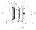
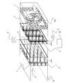
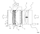
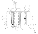
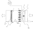
- FIG. 1 is a cross-sectional view showing a schematic longitudinal cross-sectional configuration of a microorganism / virus capture / inactivation apparatus according to Embodiment 1 of the present invention.
- 1 is a perspective view showing a schematic configuration of a microorganism / virus capturing / inactivating apparatus according to Embodiment 1 of the present invention. It is the schematic which shows roughly the structural example of the charging part high voltage electrode and trapping / inactivation part high voltage electrode which are illustrated by FIG. It is a flowchart which shows the flow of the microbe / virus capture / inactivation method which the microbe / virus capture / inactivation apparatus which concerns on Embodiment 1 of this invention performs.
- FIG. 1 is a cross-sectional view showing a schematic longitudinal cross-sectional configuration of a microorganism / virus capturing / inactivating apparatus (hereinafter referred to as apparatus 100) according to Embodiment 1 of the present invention.
- FIG. 2 is a perspective view showing a schematic configuration of the apparatus 100. Based on FIG.1 and FIG.2, the structure and operation
- the apparatus 100 captures microorganisms and viruses floating in the space (hereinafter referred to as suspended microorganisms) and inactivates the captured suspended microorganisms.
- the apparatus 100 includes an air blower 1, a charging unit high-voltage electrode (first high voltage application electrode) 2, a charging unit ground electrode (first counter electrode) 3, from the windward (upstream) side, inside the air passage housing 10.
- the trapping / inactivating part high-voltage electrode (second high voltage application electrode) 5, the hydrophilic filter 6, and the trapping / inactivating part ground electrode (second counter electrode) 7 are arranged in this order.
- the blower 1 takes air into the air passage housing 10.
- the charged portion high-voltage electrode 2 is provided with a large number of conductive thin wires (tungsten, titanium, stainless steel, platinum clad wires coated with platinum or conductive resin) having a wire diameter of about 0.05 to 0.5 mm, for example.
- a high voltage is applied from a high voltage power supply 8 that is configured by electrodes and connected thereto.
- the charged portion ground electrode 3 is composed of an electrode made of, for example, a metal mesh, and is connected to the ground.
- the charging unit high-voltage electrode 2 and the charging unit ground electrode 3 constitute a charging unit.
- the distance between the charged portion high-voltage electrode 2 and the charged portion ground electrode 3 is about 3 mm to 15 mm, and the voltage applied between the electrodes is about 1 to 15 kV.
- the first counter electrode is described as the charged portion ground electrode 3 in the embodiment, it is sufficient that a voltage is applied between the charged portion high-voltage electrode 2 and the charged portion ground electrode 3.
- the electrode 3 is not necessarily used while being grounded.
- the charged part high-voltage electrode 2 is made of a rectangular ribbon having a cross-sectional area of 0.1 mm ⁇ 0.5 mm or a similar shape thereof (the short side is the thickness of the ribbon, the thickness is 0.05 mm to 0.5 mm, the width is The same effect can be obtained even if it is made of about 0.3 mm to 1 mm and made of materials such as tungsten, titanium, stainless steel, and conductive resin.
- the charged portion high-voltage electrode 2 may be used by bending the periphery such as hemming bending or by reinforcing with an insulator or the like.
- the high voltage electrode 5 of the trapping / inactivating part is composed of, for example, an electrode in which a large number of thin wires having a wire diameter of about 0.1 mm to 0.5 mm are stretched, and a corona discharge as a partial discharge is generated from the connected high voltage power source 4 A possible high voltage of about 1 to 15 kV is applied.
- the capture / inactivation portion ground electrode 7 is composed of an electrode made of, for example, a metal mesh, and is connected to the ground.
- the second counter electrode is described as the capture / inactivation part ground electrode 7.
- a voltage is generated between the capture / inactivation part high-voltage electrode 5 and the capture / inactivation part ground electrode 7.
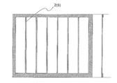
- the trapping / inactivating portion ground electrode 7 is not necessarily used while being grounded. Further, the same effect can be obtained even if the high-voltage electrode 5 of the trapping / inactivating portion is composed of a rectangular ribbon having a cross-sectional area of 0.1 mm ⁇ 0.5 mm or a similar shape thereof (thickness 0.1 mm). In this case, the surface on the short side (0.1 mm) side of the cross-sectional area may be directed toward the charged portion ground electrode 3. Alternatively, as shown in FIG.
- a flat plate (thickness 0.05 to 0.5 mm) is processed so that strips with a width of 0.3 to 1.0 mm are arranged by etching, wire processing, laser processing, sheet metal punching,
- the surroundings may be used as the high voltage electrode 5 for trapping / inactivating part by bending such as hemming bending, or by reinforcing with an insulator or the like.
- the hydrophilic filter 6 is insulated and installed by a bushing 9 so as to be sandwiched between a pair of the capture / inactivation part high-voltage electrode 5 and the capture / inactivation part ground electrode 7.
- the capturing / inactivating part high voltage electrode 5, the hydrophilic filter 6, and the capturing / inactivating part ground electrode 7 constitute a capturing / inactivating part.
- the high voltage power supply 4 can supply at least two levels of voltage to the high voltage electrode 5 for the capturing / inactivating part.
- FIG. 3 is a schematic diagram schematically showing a configuration example of the charging unit high-voltage electrode 2 and the trapping / inactivating unit high-voltage electrode 5 shown in FIG. Further, as shown in FIG. 1, the apparatus 100 is provided with a controller 50 that performs overall control of the apparatus 100. Furthermore, a controller 50 is also provided for the devices 100a to 100j described in the following embodiments.
- the hydrophilic filter 6 sandwiched between the high voltage electrode 5 of the capturing / inactivating part and the grounding electrode 7 of the capturing / inactivating part and insulated and grounded has a dielectric effect, that is, polarization.
- An electrostatic field is formed on the surface of the hydrophilic filter 6. Therefore, the floating microorganisms charged by the charging unit composed of the charging unit high-voltage electrode 2 and the charging unit ground electrode 3, that is, to which the charge is added, are attracted to the electric field formed on the surface of the hydrophilic filter 6. Will collide with.
- the microorganisms and viruses cannot be scattered again. Moreover, the microorganisms and viruses captured by the hydrophilic filter 6 are inactivated by the discharge product discharged and formed by the high-voltage electrode 5 of the capture / inactivation part.
- a part of the capturing / inactivating part is constituted by the hydrophilic filter 6, and the hydrophilic filter 6 is dielectrically induced to efficiently induce charged floating microorganisms.
- the suspended microbes that collided with the surface of the water can be held together with water. Therefore, the apparatus 100 can capture floating microorganisms with a low-pressure loss, and can prevent the captured microorganisms and viruses from re-scattering.
- the type of hydrophilic filter 6 is not particularly limited as long as it can absorb the collided water (mist-like water). In addition, if the hydrophilic filter 6 does not form water droplets on the surface of the filter when it collides with water, it is possible to suppress the re-scattering of the retained water and maintain high capture performance. Become.
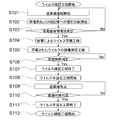
- FIG. 4 is a flowchart showing a flow of a microorganism / virus capturing / inactivating method executed by the apparatus 100.
- the feature of the apparatus 100 is that a part for trapping suspended microorganisms and a part for inactivating the captured suspended microorganisms are shared. That is, the apparatus 100 can efficiently remove microorganisms and viruses by sequentially executing the capture process of microorganisms and viruses and the inactivation process of captured microorganisms and viruses.
- step S101 When the apparatus 100 starts operation, first, the blower 1 is activated (step S101). Then, a high voltage is applied from the high voltage power source 8 to the charging unit high-voltage electrode 2, and a high voltage is applied from the high voltage power source 4 to the trapping / inactivating unit high-voltage electrode 5 (step S102). As a result, a discharge occurs between the charged portion high-voltage electrode 2 and the charged portion ground electrode 3, and a discharge current flows to the charged portion ground electrode 3.
- the current flowing through the charging unit ground electrode 3 is measured by a current determination unit provided on a control board or the like of the controller 50. The measured current value is compared with a set current value set in advance by the current determination unit (step S103). If there is no problem, the process proceeds to the next step (step S103; YES).
- step S104 If the measured current value is lower than the set current value, the voltage applied to the charged part high voltage electrode 2 is increased, and if the measured current value is higher than the set current value, it is applied to the charged part high voltage electrode 2. Voltage is lowered (step S104). In this way, it is confirmed that the floating microorganisms and viruses are always charged efficiently (step S105).
- step S104 When the microorganism / virus charging process by discharge (step S104) and the charged microorganism / virus dielectric capture process (step S105) are started, a timer is activated and the operation time of these processes is measured (step S106).
- the set current value may be set manually, or may be written in a table in advance in a predetermined combination in the storage device. Furthermore, setting this set value in relation to temperature and humidity makes it easier to obtain a predetermined charge rate.
- step S106 When the operation time of these steps reaches the set time (step S106; YES), the high voltage application to the charging unit high voltage electrode 2 is stopped and the high voltage application to the capture / inactivation unit high voltage electrode 5 is stopped. Is done. Thereafter, the series of steps (microorganism / virus capturing step) ends (step S107).
- the microorganism / virus inactivation process is started.
- a high voltage is applied from the high voltage power source 4 to the high voltage electrode 5 in the trapping / inactivating part.
- a discharge occurs between the high voltage electrode 5 of the capture / inactivation part and the ground electrode 7 of the capture / inactivation part, and a discharge current flows to the ground electrode 7 of the capture / inactivation part.
- the current flowing through the capture / inactivation part ground electrode 7 is measured by the current determination part.
- the measured current value is compared with a set current value set in advance by the current determination unit. If there is no problem, the microorganism / virus inactivation step is started as it is (step S108).
- the microorganism / virus inactivation step if the measured current value is lower than the set current value, the voltage applied to the capture / inactivation unit high-voltage electrode 5 is increased, and the measured current value is less than the set current value. If it is higher, the voltage applied to the trapping / inactivating portion high voltage electrode 5 is lowered. In this way, it is confirmed that the captured microorganisms and viruses are always inactivated efficiently.
- the microorganism / virus inactivation step by discharge step S108
- the blower 1 is stopped (step S109), the timer is activated, and the operation time of these steps is measured (step S110).
- step S110 When the operation time of these steps reaches the set time (step S110; YES), the high voltage application to the trapping / inactivation portion high voltage electrode 5 is stopped, and the inactivation step ends (step S111). Thereafter, the microorganism / virus charge / capture process is started again (step S112), and these operations are repeated.
- the step of charging the floating microorganisms (step of charging the floating microorganisms), the step of capturing the charged floating microorganisms with the dielectric hydrophilic filter 6, and the trapping with the hydrophilic filter 6 are performed.
- the portion (hydrophilic filter 6) that has captured the floating microorganisms can be always kept hygienic. Therefore, the air in the space where the apparatus 100 is installed (for example, a living space) can be always sanitary.
- Table 1 compares the pressure loss (Pa) and the transient virus capture rate (%) between the method of the apparatus 100 and the conventional filter method.
- the dielectric method of the hydrophilic filter 6 that is a method of the device 100 has a pressure loss of about 10 Pa, which is equivalent to that of a normal filter, when the wind flows at a linear velocity of 1 m / s. .
- the transient virus capture rate at that time was about 95%, which was much higher than the transient virus capture rate of 5% in the normal filter. This is considered to be because the virus can efficiently collide with the filter by the electrostatic force, and the collided virus is not re-scattered by the water adsorption force.
- the HEPA filter High Efficiency Particulate Air Filter
- the pressure loss is greatly increased.
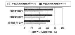
- FIG. 5 is a graph showing the relationship between the electric field strength (kV / cm) between the capture / inactivation part high voltage electrode 5 and the hydrophilic filter 6 and the transient virus capture rate (%).
- the horizontal axis represents the electric field strength
- the vertical axis represents the transient virus capture rate.
- the transient virus capture rate was about 30% (black square shown in FIG. 5).
- the transient virus capture rate was improved to 70% (open squares shown in FIG. 5).
- the hydrophilic filter 6 was dielectricized, the transient virus capture rate increased to 95% (black triangles shown in FIG. 5).
- FIG. 6 is a graph showing the investigation of the influence of the voltage polarity applied to the high-voltage electrode 2 on the transient virus capture rate (%) and ozone generation concentration (ppm).
- the horizontal axis represents the applied voltage (kV) when the distance between the charged portion high-voltage electrode 2 and the charged portion ground electrode 3 is 10 mm
- the vertical axis on the left represents the transient virus capture rate
- the vertical axis on the right The ozone generation concentration is shown respectively.
- the voltage applied by applying a negative voltage to the charged portion high-voltage electrode 2 could be reduced (black square shown in FIG. 6).
- FIG. 7 is a graph showing a study of the influence of the polarity of the voltage applied to the charged part high voltage electrode 2 and the capture / inactivation part high voltage electrode 5 on the transient virus capture rate (%).
- the transient virus capture rate was increased by making the voltage applied to the capture / inactivation part high voltage electrode 5 negative.
- the transient virus capture rate was increased by making the voltage applied to the capture / inactivation part high voltage electrode 5 positive.
- the transient virus capture rate is improved by setting the polarity of the voltage applied to the charged part high voltage electrode 2 and the capture / inactivation part high voltage electrode 5 to the opposite polarity.
- the device 100 has a structure that inactivates the virus by the discharge product derived from the discharge generated by the voltage application.
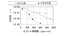
- FIG. 8 is a graph showing a comparison of virus survival rates when the captured virus is treated only with ozone gas and when not only ozone gas but also other discharge products are used (plasma treatment). Is.
- the horizontal axis represents ozone concentration ⁇ time product (ppm ⁇ min), and the vertical axis represents survival rate ( ⁇ ).
- ppm ⁇ min time product
- ⁇ survival rate
- FIG. 8 even when the ozone concentration was the same, the virus could be inactivated in a short time by treating it with a plasma field. This is considered to be because the virus is inactivated by electrons, radicals, ions, etc. in the plasma by installing the trapped virus in the plasma field.
- a filter that removes coarse dust in the air before charging floating microorganisms is not described.
- a filter that removes coarse dust before air flows into a charged portion that charges floating microorganisms.
- the case where the blower 1 is installed on the windward side and the air is pushed into the virus capturing unit has been described.
- the blower 1 is installed on the leeward side and air is sucked from the virus capturing unit. Needless to say, the same bactericidal effect can be obtained.
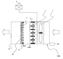
- FIG. FIG. 9 is a cross-sectional view showing a schematic longitudinal cross-sectional configuration of a microorganism / virus capturing / inactivating apparatus (hereinafter referred to as apparatus 100a) according to Embodiment 2 of the present invention. Based on FIG. 9, the configuration and operation of the apparatus 100a will be described. In the second embodiment, differences from the first embodiment will be mainly described, and the same parts as those in the first embodiment are denoted by the same reference numerals. In FIG. 9, the air flow is indicated by arrows.
- a charging unit including a charging unit high-voltage electrode 2 and a charging unit ground electrode 11 is provided on the leeward side of the blower 1. That is, apparatus 100a is different from apparatus 100 according to Embodiment 1 in the configuration of the charging unit.
- the charged portion high-voltage electrode 2 is composed of an electrode in which a large number of conductive thin wires having a wire diameter of about 0.1 mm to 0.3 mm are stretched, for example, so that a high voltage is applied from the connected high voltage power supply 8. It has become.
- the charged portion ground electrode 11 is formed of an electrode made of a metal plate, for example, and is connected to the ground.
- the entire amount of air taken into the discharge space (space a shown in FIG. 9) formed by the charged portion high-voltage electrode 2 and the charged portion ground electrode 11 The airborne microorganisms in the air can be efficiently charged. Therefore, according to the apparatus 100a, the capture rate of microorganisms / viruses in the capture / inactivation part including the capture / inactivation part high-voltage electrode 5, the hydrophilic filter 6, and the capture / inactivation part ground electrode 7 is maximized. Can be increased.
- the charged portion high-voltage electrode 2 is made of a conductive ribbon having a rectangular shape with a cross-sectional area of 0.1 mm ⁇ 0.5 mm or a similar shape (thickness 0.1 mm to 0.3 mm, material tungsten, titanium, stainless steel, conductive resin, etc. The same effect can be obtained even if it is configured with). In this case, the surface on the short side (0.1 mm) side of the cross-sectional area can be more efficiently charged if the surface is directed to the charged portion ground electrode 11, and the influence of disconnection due to electrode wear due to sputtering during discharge is affected. There is an effect that can be reduced.
- FIG. 10 is a cross-sectional view showing a schematic longitudinal cross-sectional configuration of a microorganism / virus capture / inactivation apparatus (hereinafter referred to as apparatus 100b) according to Embodiment 3 of the present invention. Based on FIG. 10, the configuration and operation of the apparatus 100b will be described. In the third embodiment, differences from the first and second embodiments will be mainly described, and the same parts as those in the first and second embodiments are denoted by the same reference numerals. In FIG. 10, the air flow is indicated by arrows.
- the charging unit high-voltage electrode 2 made of a thin wire is installed on the leeward side, and the charging unit ground electrode 3 made of a wire mesh is installed on the leeward side, so that floating microorganisms in the air are charged.
- the charged portion high-voltage electrode 12 is constituted by an electrode provided with a plurality of conductive protrusions.
- the charged portion high-voltage electrode 12 may be configured by attaching protrusions to a wire mesh or plate through which air can pass without pressure loss by welding or the like.
- the charged portion high-voltage electrode 12 may be configured so that a metal plate is cut with a wire cutter or the like to form a protruding portion.
- the charging unit high-voltage electrode 12 can be prevented from being damaged by abnormal discharge due to dust flowing in from the outside, and stable discharge can be maintained. It becomes easy.
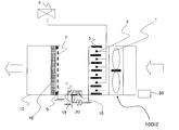
- FIG. 11 is a cross-sectional view showing a schematic longitudinal cross-sectional configuration of a microorganism / virus capture / inactivation apparatus (hereinafter referred to as apparatus 100c) according to Embodiment 4 of the present invention. Based on FIG. 11, the configuration and operation of the apparatus 100c will be described. In the fourth embodiment, differences from the first to third embodiments will be mainly described, and the same parts as those in the first to third embodiments are denoted by the same reference numerals. In FIG. 11, the air flow is indicated by arrows.
- the high-voltage power supply 8 supplied to the charging unit high-voltage electrode 2 and the high-voltage power supply 4 supplied to the capture / inactivation unit high-voltage electrode 5 are configured.
- a voltage is supplied from the high-voltage power supply 4 to both the charging unit high-voltage electrode 2 and the capture / inactivation unit high-voltage electrode 5.
- a safety guard 13 is provided in the lee of the device 100c to prevent a user from accidentally putting a finger or the like.
- the safety guard 13 is made of, for example, a mesh having a conductivity of about 1 to 10 mm that can be inserted by a human finger, and is kept at a potential of 0 by being grounded.
- FIG. 12 is a flowchart showing a flow of a microorganism / virus capturing / inactivating method executed by the apparatus 100c.
- a feature of the apparatus 100c is that a part for capturing the suspended microorganism and a part for inactivating the captured suspended microorganism are shared, and the same power source is used in both processes. That is, the apparatus 100c can efficiently remove microorganisms and viruses by sequentially executing the capture process of microorganisms and viruses and the inactivation process of captured microorganisms and viruses.
- step S201 When the apparatus 100c starts operation, first, the blower 1 is activated (step S201). Then, a high voltage is applied from the high voltage power supply 4 to the charging unit high voltage electrode 2, and a high voltage is also applied from the high voltage power supply 4 to the capture / inactivation unit high voltage electrode 5 (step S202). As a result, a discharge occurs between the charged portion high-voltage electrode 2 and the charged portion ground electrode 3, and a discharge current flows to the charged portion ground electrode 3.
- the current flowing through the charging unit ground electrode 3 is measured by a current determination unit provided on a control board or the like of the controller 50. The measured current value is compared with a preset current value set in advance by the current determination unit (step S203). If there is no problem, the process proceeds to the next step (step S203; YES).
- step S204 If the measured current value is lower than the set current value, the voltage applied to the charged part high voltage electrode 2 is increased, and if the measured current value is higher than the set current value, it is applied to the charged part high voltage electrode 2. Voltage is lowered (step S204). In this way, it is confirmed that floating microorganisms and viruses are always charged efficiently (step S205).
- step S204 When the microorganism / virus charging process by discharge (step S204) and the charged microorganism / virus dielectric capture process (step S205) are started, a timer is activated and the operation time of these processes is measured (step S206).
- step S206 When the operation time of these steps reaches the set time (step S206; YES), high voltage application to the charging unit high voltage electrode 2 is stopped and high voltage application to the trapping / inactivation unit high voltage electrode 5 is stopped. Is done. Thereafter, the blower 1 is stopped (step S207), and the series of steps (microorganism / virus capturing step) is ended (step S208).
- the microorganism / virus inactivation process is started.
- a high voltage is applied from the high voltage power source 4 to the high voltage electrode 5 in the trapping / inactivating part.
- a discharge occurs between the high voltage electrode 5 of the capture / inactivation part and the ground electrode 7 of the capture / inactivation part, and a discharge current flows to the ground electrode 7 of the capture / inactivation part.
- the current flowing through the capture / inactivation part ground electrode 7 is measured by the current determination part.
- the measured current value is compared with a set current value set in advance by the current determination unit. If there is no problem, the microorganism / virus inactivation step is started as it is (step S209).
- the microorganism / virus inactivation step if the measured current value is lower than the set current value, the voltage applied to the capture / inactivation unit high-voltage electrode 5 is increased, and the measured current value is less than the set current value. If it is higher, the voltage applied to the trapping / inactivating portion high voltage electrode 5 is lowered. In this way, it is confirmed that the captured microorganisms and viruses are always inactivated efficiently.
- a timer is activated and the operation time of these processes is measured (step S210).
- step S210 When the operation time of these steps reaches the set time (step S210; YES), the high voltage application to the trapping / inactivation portion high voltage electrode 5 is stopped, and the inactivation step ends (step S211). Thereafter, the microorganism / virus charge / capture process is started again (step S212), and these operations are repeated.
- the step of charging the floating microorganisms (step of charging the floating microorganisms), the step of capturing the charged floating microorganisms with the dielectric hydrophilic filter 6, and the trapping with the hydrophilic filter 6 are performed.
- the portion (hydrophilic filter 6) that has captured the floating microorganisms can be always kept hygienic.
- the blower 1 In the inactivation process, the blower 1 is stopped, and the discharge between the charged part high voltage electrode 2 and the charged part ground electrode 3 is continued from the microorganism / virus inactivation process. At this time, the ozone concentration in the part (hydrophilic filter 6) captured by the blower 1 being stopped increases. At the time of inactivation, when ozone and plasma are used in combination, the treatment can be performed in a shorter time as the ozone concentration is higher.
- the grounded safety guard 13 prevents the user from accidentally coming into contact with the high voltage, and neutralizes the charged particles such as ions with the safety guard 13 so that the charged particles It is possible to prevent discharge from the apparatus 100c. Therefore, the air in the space where the device 100c is installed (for example, a living space) can be always hygienic.
- FIG. FIG. 13 is a cross-sectional view showing a schematic cross-sectional configuration of a microorganism / virus capture / inactivation apparatus (hereinafter referred to as apparatus 100d) according to Embodiment 5 of the present invention.
- FIG. 14 is a cross-sectional view showing a schematic cross-sectional configuration of a modified example of the device 100g (hereinafter referred to as the device 100e).
- FIG. 15 is a cross-sectional view illustrating a schematic cross-sectional configuration of a modified example of the device 100d (hereinafter, referred to as a device 100f).
- the configurations and operations of the devices 100d to 100f will be described with reference to FIGS.
- differences from the first to fourth embodiments will be mainly described, and the same parts as those in the first to fourth embodiments are denoted by the same reference numerals.
- the air flow is indicated by arrows.
- the voltage is supplied from the high-voltage power supply 4 to both the charging unit high-voltage electrode 2 and the capture / inactivation unit high-voltage electrode 5 as shown in FIG.
- the voltage supplied to the high voltage electrode 5 of the trapping / inactivating part can be adjusted by the voltage regulator 14.
- a voltage is applied to the charged part high-voltage electrode 2 from the high-voltage power supply 4, and a discharge occurs between the charged part high-voltage electrode 2 and the charged part ground electrode 3. .
- a voltage is applied to the capture / inactivation part high-voltage electrode 5 from the high-voltage power supply 4 to form an electric field between the capture / inactivation part high-voltage electrode 5 and the capture / inactivation part ground electrode 7. ⁇ The virus is being captured.
- the voltage regulator 14 is attached to the device 100d.
- the voltage regulator 14 applies a voltage to the trapping / inactivating portion high-voltage electrode 5 by, for example, connecting high-voltage resistors in series and dividing the voltage by the resistance ratio. This makes it possible to apply different voltages to the charging unit high-voltage electrode 2 and the trapping / inactivating unit high-voltage electrode 5.
- a signal can be sent from the controller 50 to the voltage adjusting device 14, and different voltages can be applied during trapping and inactivation.
- the voltage adjusting device 14 is connected to the high voltage electrode 5 of the capturing / inactivating portion, but the voltage adjusting device 14a is captured to the high voltage electrode 2 of the charging portion as in the device 100e shown in FIG. -You may comprise by connecting the voltage regulator 14b to the inactivation part high voltage electrode 5.
- FIG. Thereby, the voltage applied to the charged part and the capture / inactivation part can be freely changed, and the voltage setting according to the microorganism / virus removal environmental conditions is set to each of the charge part and the capture / inactivation part. It becomes possible.
- the charging unit high voltage electrode 2 and the trapping / inactivating unit high voltage can be obtained even if different voltages can be supplied to each of the electrodes 5.
- the air in the space where the devices 100d to 100f are installed (for example, a living space) can be always hygienic.
- FIG. 16 is a cross-sectional view showing a schematic longitudinal cross-sectional configuration of a microorganism / virus capturing / inactivating apparatus (hereinafter referred to as apparatus 100g1) according to Embodiment 6 of the present invention.
- FIG. 17 is a cross-sectional view showing a schematic vertical cross-sectional configuration of a modified example of the device 100g1 (hereinafter referred to as the device 100g2).
- the configuration and operation of the device 100g1 and the device 100g2 will be described with reference to FIGS.
- differences from the first to fifth embodiments will be mainly described, and the same parts as those in the first to fifth embodiments are denoted by the same reference numerals.
- FIG.16 and FIG.17 the flow of air is shown by the arrow.
- the capturing part is configured by the capturing / inactivating part high-voltage electrode 5, the hydrophilic filter 6, and the capturing / inactivating part ground electrode 7, and the capturing / inactivating part
- the high-voltage electrode 5 is connected to the high-voltage power supply 4, the capture / inactivation part ground electrode 7 is grounded, and the hydrophilic filter 6 is sandwiched between the pair of electrodes so as to capture airborne microorganisms in the air.
- the hydrophilic filter is constituted by a honeycomb structure (hereinafter referred to as honeycomb 15) carrying a hydrophilic adsorbent on the surface.
- the honeycomb 15 is constituted by carrying a hydrophilic adsorbent on a honeycomb surface made of, for example, metal (stainless steel, aluminum, etc.), ceramic, paper or the like.
- a hydrophilic adsorbent for example, hydrophilic zeolite or the like is effective, but the type is not particularly limited as long as the adsorbent has a high water hygroscopicity.
- the honeycomb 15 can be obtained, for example, by immersing a metal honeycomb in a slurry-like solution in which activated carbon is dissolved and firing it at an appropriate temperature after drying.
- the trapping part is composed of the trapping / inactivation part high-voltage electrode 5, the honeycomb 15, and the trapping / inactivation part ground electrode 7, so that not only floating microorganisms but also chemical substances such as odor components can be increased. The effect that it can capture efficiently is acquired.
- a hydrophilic adsorbent is attached to a honeycomb member made of metal or the like.
- manganese dioxide (MnO 2 ), titanium dioxide (TiO 2 ) You may make it carry
- the catalyst itself can be activated during the plasma treatment, or the catalyst can convert the discharge product into a more active substance.
- Viruses and microorganisms can be inactivated in a short time.
- chemical substances attached to the honeycomb 15 can be decomposed and removed.
- the honeycomb 15 may be composed of two or more types of honeycombs (for example, the hydrophilic honeycomb 15a and the catalyst-implanted honeycomb 15b).
- the hydrophilic honeycomb 15a may be provided on the side close to the charging portion (upstream side)
- the catalyst-added honeycomb 15b may be provided on the side remote from the charging portion (downstream side). That is, the honeycomb installed closest to the charged portion may be made hydrophilic, and the other honeycombs are not particularly limited.
- An adsorbent for adsorbing odor gas, a catalyst for decomposing and reducing the odor components described above, and the like are attached to the catalyst-added honeycomb 15b.
- the catalyst-impregnated honeycomb 15b may be either hydrophilic or hydrophobic, but a combination of hydrophilic and hydrophobic adsorbents is added because the number of gases that can be adsorbed or decomposed increases. It is preferable to constitute by this.
- the discharge product for example, ozone
- the discharge product for example, ozone
- the capture efficiency of floating microorganisms in the capture unit can be increased to the limit, and the removal efficiency of viruses and microorganisms is further improved.
- FIG. FIG. 18 is a cross-sectional view showing a schematic longitudinal cross-sectional configuration of a microorganism / virus capture / inactivation apparatus (hereinafter, referred to as apparatus 100h) according to Embodiment 7 of the present invention. Based on FIG. 18, the configuration and operation of the apparatus 100h will be described. In the seventh embodiment, differences from the first to sixth embodiments will be mainly described, and the same parts as those in the first to sixth embodiments are denoted by the same reference numerals. In FIG. 18, the air flow is indicated by arrows.
- the capturing part is configured by the capturing / inactivating part high voltage electrode 5, the hydrophilic filter 6, and the capturing / inactivating part ground electrode 7, and the capturing / inactivating part
- the high-voltage electrode 5 is connected to the high-voltage power supply 4, the capture / inactivation part ground electrode 7 is grounded, and the hydrophilic filter 6 is sandwiched between the pair of electrodes so as to capture airborne microorganisms in the air.
- the electrostatic filter 16 and the capture / inactivation part ground electrode 7 installed on the upstream side of the filter via an insulator (bushing 9) are configured. ing.
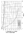
- FIG. 19 shows an example of changes in the microorganism / virus capture rate when the capture / inactivation portion ground electrode 7 is included in the configuration and when it is not included.
- the horizontal axis represents the time from the start of capture, and the vertical axis represents the change rate of the microorganism / virus capture rate when time 0 minutes is set to 1.
- the microorganism / virus capture rate decreases with time, whereas on the windward side of the electrostatic filter 16,
- the microorganism / virus capture rate can be maintained with high efficiency.
- the ions generated in the charging unit generate an electric field in the opposite direction to that generated by the charging unit electrodes (charging unit high-voltage electrode 2 and charging unit ground electrode 3) generated by being deposited on the electrostatic filter 16.
- the electric field in the direction opposite to that generated by the charged portion electrode serves to reduce the charging efficiency of the charged portion.
- the trapping / inactivating part ground electrode 7 neutralizes ions generated by the charging part electrode, thereby preventing charge accumulation in the electrostatic filter 16 and maintaining the microorganism / virus trapping rate with high efficiency.
- the microorganisms / viruses captured by the electrostatic filter 16 can be inactivated by exposing ozone generated between the charged portion high-voltage electrode 2 and the charged portion ground electrode 3 for a long time.
- the electrostatic filter 16 has a honeycomb shape (infinite number of holes, that is, a shape having partition walls), it can be configured with low pressure loss.
- the air in the space where the device 100h is installed (for example, a living space) can be always hygienic.
- the electrostatic filter 16 is desirably in a state having permanent static electricity.
- FIG. 20 is a cross-sectional view showing a schematic longitudinal cross-sectional configuration of a microorganism / virus capture / inactivation apparatus (hereinafter, referred to as apparatus 100i1) according to Embodiment 8 of the present invention.
- FIG. 21 is a cross-sectional view showing another example of a schematic longitudinal cross-sectional configuration of a microorganism / virus capture / inactivation apparatus (hereinafter, referred to as apparatus 100i2) according to Embodiment 8 of the present invention.
- apparatus 100i2 the configuration and operation of the device 100i1 and the device 100i2 will be described.
- differences from the first to seventh embodiments will be mainly described, and the same parts as those in the first to seventh embodiments are denoted by the same reference numerals. 20 and 21, the air flow is indicated by arrows.
- the charging unit high-voltage electrode (charging unit high-voltage electrode 2, charging unit high-voltage electrode 12) is installed on the windward side, and the charging unit ground electrode (charging unit grounding electrode 3, charging unit grounding electrode). 11) is installed on the leeward side so that the floating microorganisms in the air are charged and inactivated by the ozone generated by the charged portion high-voltage electrode 2 and the charged portion ground electrode 3 when inactivated.
- form 8 as shown in FIG. 20, between the charged part (charge part high voltage electrode 2, charged part ground electrode 3) and the capture / inactivation part (electrostatic filter 16, capture / inactivation part ground electrode 7).
- a discharge electrode (first high voltage application electrode) 17, a ground electrode 18, a fan 19, and a high voltage power supply 8 are provided on an inner surface of the air passage housing 10, for example, on a wall surface to generate ions To charge the floating microorganisms There.
- a charging mist generating unit including the charging mist spray electrode 20, the ground electrode 18, the fan 19, and the high voltage power supply 8 is provided on, for example, a wall surface inside the air passage housing 10.
- the floating microorganisms may be charged with a charging mist.
- the number of parts increases, but microorganisms / viruses can be quickly inactivated.
- FIG. FIG. 22 is a cross-sectional view showing a schematic longitudinal cross-sectional configuration of a microorganism / virus capture / inactivation apparatus (hereinafter, referred to as apparatus 100j) according to Embodiment 9 of the present invention. Based on FIG. 22, the configuration and operation of the apparatus 100j will be described. In the ninth embodiment, differences from the first to eighth embodiments will be mainly described, and the same parts as those in the first to eighth embodiments are denoted by the same reference numerals. Further, in FIG. 22, the air flow is indicated by arrows.
- the charging unit high-voltage electrode (charging unit high-voltage electrode 2, charging unit high-voltage electrode 12) is installed on the windward side, and the charging unit ground electrode (charging unit grounding electrode 3, charging unit grounding electrode). 11) is installed on the leeward side so that the floating microorganisms in the air are charged and inactivated by the ozone generated by the charged portion high-voltage electrode 2 and the charged portion ground electrode 3 when inactivated.
- the ninth embodiment as shown in FIG. 22, between the charged part (charged part high-voltage electrode 2, charged part grounded electrode 3) and the capture / inactivation part (electrostatic filter 16, capture / inactivated part grounded electrode 7).
- a humidifier 21 is provided to mix the floating microorganisms charged by the charging unit and the water supplied from the humidifier 21.
- moisture can be supplied to the charged floating microorganisms. It becomes possible to increase more.
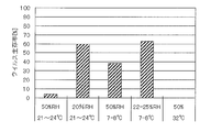
- FIG. 23 shows changes in the survival rate after leaving the influenza virus for 6 hours in a state where nothing is done by changing the temperature and humidity.
- the activity of viruses increases at low temperatures and low humidity, and the activity decreases at high temperatures and high humidity.
- the activity of microorganisms increases at a relatively high temperature and is weak against drying, so that the activity decreases at low humidity. Therefore, virus can be inactivated more effectively by supplying water during virus inactivation.
- microorganism / virus capture / inactivation apparatus and method have been described separately in the first to ninth embodiments, the features of each embodiment can be combined as appropriate to control the microorganism / virus. You may make it comprise a capture and inactivation apparatus and its method.
Abstract
Description
実施の形態1.
図1は、本発明の実施の形態1に係る微生物・ウイルスの捕捉・不活化装置(以下、装置100と称する)の概略縦断面構成を示す断面図である。図2は、装置100の概略構成を示す斜視図である。図1及び図2に基づいて、装置100の構成及び動作について説明する。なお、図1を含め、以下の図面では各構成部材の大きさの関係が実際のものとは異なる場合がある。また、図1及び図2では、空気の流れを矢印で示している。 Hereinafter, embodiments of the present invention will be described with reference to the drawings.
FIG. 1 is a cross-sectional view showing a schematic longitudinal cross-sectional configuration of a microorganism / virus capturing / inactivating apparatus (hereinafter referred to as apparatus 100) according to
図4は、装置100が実行する微生物・ウイルスの捕捉・不活化方法の流れを示すフローチャートである。装置100の特徴は、浮遊微生物を捕捉する部分と、捕捉した浮遊微生物を不活化する部分と、を共通化した点である。すなわち、装置100は、微生物やウイルスの捕捉処理と、捕捉した微生物やウイルスの不活化処理と、をシーケンシャルに実行可能としたことにより、効率的に微生物やウイルスを除去できるようになっている。 Next, the operation of the
FIG. 4 is a flowchart showing a flow of a microorganism / virus capturing / inactivating method executed by the
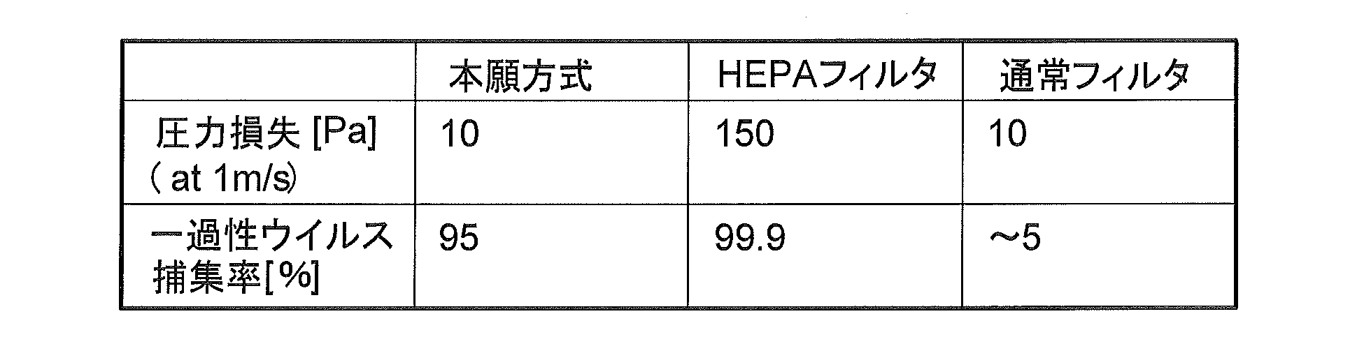
図9は、本発明の実施の形態2に係る微生物・ウイルスの捕捉・不活化装置(以下、装置100aと称する)の概略縦断面構成を示す断面図である。図9に基づいて、装置100aの構成及び動作について説明する。なお、実施の形態2では実施の形態1との相違点を中心に説明し、実施の形態1と同一部分には、同一符号を付している。また、図9では、空気の流れを矢印で示している。
FIG. 9 is a cross-sectional view showing a schematic longitudinal cross-sectional configuration of a microorganism / virus capturing / inactivating apparatus (hereinafter referred to as
図10は、本発明の実施の形態3に係る微生物・ウイルスの捕捉・不活化装置(以下、装置100bと称する)の概略縦断面構成を示す断面図である。図10に基づいて、装置100bの構成及び動作について説明する。なお、実施の形態3では実施の形態1及び実施の形態2との相違点を中心に説明し、実施の形態1及び実施の形態2と同一部分には、同一符号を付している。また、図10では、空気の流れを矢印で示している。
FIG. 10 is a cross-sectional view showing a schematic longitudinal cross-sectional configuration of a microorganism / virus capture / inactivation apparatus (hereinafter referred to as
図11は、本発明の実施の形態4に係る微生物・ウイルスの捕捉・不活化装置(以下、装置100cと称する)の概略縦断面構成を示す断面図である。図11に基づいて、装置100cの構成及び動作について説明する。なお、実施の形態4では実施の形態1~実施の形態3との相違点を中心に説明し、実施の形態1~実施の形態3と同一部分には、同一符号を付している。また、図11では、空気の流れを矢印で示している。
FIG. 11 is a cross-sectional view showing a schematic longitudinal cross-sectional configuration of a microorganism / virus capture / inactivation apparatus (hereinafter referred to as
図12は、装置100cが実行する微生物・ウイルスの捕捉・不活化方法の流れを示すフローチャートである。装置100cの特徴は、浮遊微生物を捕捉する部分と、捕捉した浮遊微生物を不活化する部分と、を共通化し、両方の過程において同一の電源で構成した点である。すなわち、装置100cは、微生物やウイルスの捕捉処理と、捕捉した微生物やウイルスの不活化処理と、をシーケンシャルに実行可能としたことにより、効率的に微生物やウイルスを除去できるようになっている。 Next, the operation of the
FIG. 12 is a flowchart showing a flow of a microorganism / virus capturing / inactivating method executed by the
図13は、本発明の実施の形態5に係る微生物・ウイルスの捕捉・不活化装置(以下、装置100dと称する)の概略断面構成を示す断面図である。図14は、装置100gの変形例(以下、装置100eと称する)の概略断面構成を示す断面図である。図15は、装置100dの変形例(以下、装置100fと称する)の概略断面構成を示す断面図である。図13~図15に基づいて、装置100d~装置100fの構成及び動作について説明する。なお、実施の形態5では実施の形態1~実施の形態4との相違点を中心に説明し、実施の形態1~実施の形態4と同一部分には、同一符号を付している。また、図13~図15では、空気の流れを矢印で示している。
FIG. 13 is a cross-sectional view showing a schematic cross-sectional configuration of a microorganism / virus capture / inactivation apparatus (hereinafter referred to as
図16は、本発明の実施の形態6に係る微生物・ウイルスの捕捉・不活化装置(以下、装置100g1と称する)の概略縦断面構成を示す断面図である。図17は、装置100g1の変形例(以下、装置100g2と称する)の概略縦断面構成を示す断面図である。図16及び図17に基づいて、装置100g1及び装置100g2の構成及び動作について説明する。なお、実施の形態6では実施の形態1~実施の形態5との相違点を中心に説明し、実施の形態1~実施の形態5と同一部分には、同一符号を付している。また、図16及び図17では、空気の流れを矢印で示している。
FIG. 16 is a cross-sectional view showing a schematic longitudinal cross-sectional configuration of a microorganism / virus capturing / inactivating apparatus (hereinafter referred to as apparatus 100g1) according to
図18は、本発明の実施の形態7に係る微生物・ウイルスの捕捉・不活化装置(以下、装置100hと称する)の概略縦断面構成を示す断面図である。図18に基づいて、装置100hの構成及び動作について説明する。なお、実施の形態7では実施の形態1~実施の形態6との相違点を中心に説明し、実施の形態1~実施の形態6と同一部分には、同一符号を付している。また、図18では、空気の流れを矢印で示している。
FIG. 18 is a cross-sectional view showing a schematic longitudinal cross-sectional configuration of a microorganism / virus capture / inactivation apparatus (hereinafter, referred to as
図20は、本発明の実施の形態8に係る微生物・ウイルスの捕捉・不活化装置(以下、装置100i1と称する)の概略縦断面構成を示す断面図である。図21は、本発明の実施の形態8に係る微生物・ウイルスの捕捉・不活化装置(以下、装置100i2と称する)の概略縦断面構成の別の例を示す断面図である。図20及び図21に基づいて、装置100i1及び装置100i2の構成及び動作について説明する。なお、実施の形態8では実施の形態1~実施の形態7との相違点を中心に説明し、実施の形態1~実施の形態7と同一部分には、同一符号を付している。また、図20及び図21では、空気の流れを矢印で示している。
FIG. 20 is a cross-sectional view showing a schematic longitudinal cross-sectional configuration of a microorganism / virus capture / inactivation apparatus (hereinafter, referred to as apparatus 100i1) according to
図22は、本発明の実施の形態9に係る微生物・ウイルスの捕捉・不活化装置(以下、装置100jと称する)の概略縦断面構成を示す断面図である。図22に基づいて、装置100jの構成及び動作について説明する。なお、実施の形態9では実施の形態1~実施の形態8との相違点を中心に説明し、実施の形態1~実施の形態8と同一部分には、同一符号を付している。また、図22では、空気の流れを矢印で示している。
FIG. 22 is a cross-sectional view showing a schematic longitudinal cross-sectional configuration of a microorganism / virus capture / inactivation apparatus (hereinafter, referred to as
Claims (10)
- 浮遊微生物を風路筐体内に取り込む工程と、
前記風路筐体内に取り込んだ浮遊微生物を荷電する荷電工程と、
前記荷電された浮遊微生物を誘電されたフィルターで捕捉するフィルター補足工程と、
前記フィルターで捕捉した浮遊微生物をプラズマで不活化する工程と、を有し、
前記荷電工程、前記フィルター捕捉工程が終了した後に、前記フィルターで捕捉した浮遊微生物をプラズマで不活化する工程を開始する
ことを特徴とする微生物・ウイルスの捕捉・不活化方法。 Taking airborne microorganisms into the airway housing;
A charging step for charging the floating microorganisms taken into the air passage housing;
A filter supplementing step of capturing the charged floating microorganisms with a dielectric filter;
And inactivating the suspended microorganisms captured by the filter with plasma,
After the charging step and the filter capturing step are finished, a step of inactivating the suspended microorganisms captured by the filter with plasma is started. A method for capturing and inactivating microorganisms / viruses. - 上記工程が連続的に行われる
ことを特徴とする請求項1記載の微生物・ウイルスの捕捉・不活化方法 The method for capturing / inactivating microorganisms / viruses according to claim 1, wherein the steps are continuously performed. - 前記フィルターが親水性である
ことを特徴とする請求項1又は2記載の微生物・ウイルスの捕捉・不活化方法 The method for capturing / inactivating microorganisms / viruses according to claim 1 or 2, wherein the filter is hydrophilic. - 風路筐体と、
電圧が印加され、前記風路筐体内に取り込んだ浮遊微生物を荷電する第1高電圧印加電極と、
前記第1高電圧印加電極と対向して設置された第1対向電極と、
前記第1高電圧印加電極により荷電された浮遊微生物を捕捉する第2高電圧印加電極と第2対向電極との間に挟まれたフィルターと、
前記第1高電圧印加電極と前記第2高電圧印加電極に電圧を供給する1つの高電圧電源と、
を備えた
ことを特徴とする請求項1~3のいずれか一項に記載の微生物・ウイルスの捕捉・不活化方法。 An airway housing;
A first high voltage application electrode to which a voltage is applied and charges floating microorganisms taken into the air passage housing;
A first counter electrode disposed to face the first high voltage application electrode;
A filter sandwiched between a second high voltage application electrode and a second counter electrode for capturing floating microorganisms charged by the first high voltage application electrode;
One high voltage power source for supplying a voltage to the first high voltage application electrode and the second high voltage application electrode;
The microorganism / virus capturing / inactivating method according to any one of claims 1 to 3, wherein the microorganism / virus capturing / inactivating method is provided. - 風路筐体と、
電圧が印加され、前記風路筐体内に取り込んだ浮遊微生物を荷電する第1高電圧印加電極と、
前記第1高電圧印加電極と対向して設置された第1対向電極と、
前記第1高電圧印加電極により荷電された浮遊微生物を捕捉する予め帯電されたフィルターと、
前記フィルターの風上に設けられた接地電極と、
を備えた
ことを特徴とする請求項1~3のいずれか一項に記載の微生物・ウイルスの捕捉・不活化方法。 An airway housing;
A first high voltage application electrode to which a voltage is applied and charges floating microorganisms taken into the air passage housing;
A first counter electrode disposed to face the first high voltage application electrode;
A pre-charged filter that captures suspended microorganisms charged by the first high voltage application electrode;
A ground electrode provided on the windward side of the filter;
The microorganism / virus capturing / inactivating method according to any one of claims 1 to 3, wherein the microorganism / virus capturing / inactivating method is provided. - 前記フィルターには、
親水性触媒、吸着剤、及び、脱臭触媒のうち少なくとも一つが添着されている
ことを特徴とする請求項1~5のいずれか一項に記載の微生物・ウイルスの捕捉・不活化方法。 The filter includes
6. The microorganism / virus capturing / inactivating method according to claim 1, wherein at least one of a hydrophilic catalyst, an adsorbent, and a deodorizing catalyst is attached. - 浮遊微生物を風路筐体内に取り込む工程と、
前記風路筐体内において第1高電圧印加電極と該第1高電圧印加電極と対向して設置された第1対向電極との間に放電を起こし、前記風路筐体内に取り込んだ浮遊微生物を荷電する工程と、
前記荷電された浮遊微生物を予め帯電されたフィルターで捕捉する補足工程と、
前記捕捉工程および送風終了後に浮遊微生物を不活化する工程と、を有し、
上記工程が連続的に行われる
ことを特徴とする微生物・ウイルスの捕捉・不活化方法。 Taking airborne microorganisms into the airway housing;
In the air passage housing, a discharge is caused between the first high voltage applying electrode and the first counter electrode disposed opposite to the first high voltage applying electrode, and the floating microorganisms taken into the air passage housing Charging step;
A supplementary step of capturing the charged floating microorganisms with a pre-charged filter;
A step of inactivating the floating microorganisms after the capturing step and the air blowing,
A method for capturing and inactivating microorganisms / viruses, characterized in that the above steps are carried out continuously. - 風路筐体と、
電圧が印加され、前記風路筐体内に取り込んだ浮遊微生物を荷電する第1高電圧印加電極と、
前記第1高電圧印加電極と対向して設置された第1対向電極と、
前記第1高電圧印加電極により荷電された浮遊微生物を捕捉するフィルターと、
電圧が印加され、前記フィルターを誘電し、かつ、前記フィルターに捕捉した浮遊微生物を不活化する第2高電圧印加電極と、
前記第2高電圧印加電極と対向して設置された第2対向電極と、
前記第1高電圧印加電極、前記第2高電圧印加電極に電圧を印加するための電源と、
を備え、
前記フィルターの表面は、親水性を有し 、
前記フィルターは、
前記第2高電圧印加電極と前記第2対向電極との間に絶縁的に挟み込んで設置される
ことを特徴とする微生物・ウイルスの捕捉・不活化装置。 An airway housing;
A first high voltage application electrode to which a voltage is applied and charges floating microorganisms taken into the air passage housing;
A first counter electrode disposed to face the first high voltage application electrode;
A filter for capturing suspended microorganisms charged by the first high voltage application electrode;
A second high voltage application electrode to which a voltage is applied, which inducts the filter and inactivates suspended microorganisms captured by the filter;
A second counter electrode disposed opposite to the second high voltage application electrode;
A power source for applying a voltage to the first high voltage application electrode and the second high voltage application electrode;
With
The surface of the filter has hydrophilicity,
The filter is
A microorganism / virus capturing / inactivating device, wherein the device is installed so as to be insulatively sandwiched between the second high voltage application electrode and the second counter electrode. - 前記第1高電圧印加電極及び前記第2高電圧印加電極のうち少なくとも一つに印加する電圧を調整可能にした
ことを特徴とする請求項8に記載の微生物・ウイルスの捕捉・不活化装置。 9. The microorganism / virus capturing / inactivating device according to claim 8, wherein a voltage applied to at least one of the first high voltage application electrode and the second high voltage application electrode is adjustable. - 前記第1高電圧印加電極及び前記第2高電圧印加電極のうち少なくとも一つに印加する電圧を同一の電源から供することを可能とした
ことを特徴とする請求項8に記載の微生物・ウイルスの捕捉・不活化装置。 The microorganism / virus virus according to claim 8, wherein a voltage applied to at least one of the first high voltage application electrode and the second high voltage application electrode can be supplied from the same power source. Capture and inactivation device.
Priority Applications (4)
| Application Number | Priority Date | Filing Date | Title |
|---|---|---|---|
| CN201280042878.0A CN103764178B (en) | 2011-11-02 | 2012-10-18 | The seizure inactivating device of microbial virus and method thereof |
| JP2013541700A JP5855122B2 (en) | 2011-11-02 | 2012-10-18 | Microbe / virus capture / inactivation apparatus and method thereof |
| US14/241,612 US9216233B2 (en) | 2011-11-02 | 2012-10-18 | Apparatus and method for capture and inactivation of microbes and viruses |
| EP12845939.3A EP2774628B1 (en) | 2011-11-02 | 2012-10-18 | Device and method for trapping and inactivating micro-organisms and viruses |
Applications Claiming Priority (4)
| Application Number | Priority Date | Filing Date | Title |
|---|---|---|---|
| JP2011241636 | 2011-11-02 | ||
| JP2011-241636 | 2011-11-02 | ||
| PCT/JP2012/002184 WO2013065206A1 (en) | 2011-11-02 | 2012-03-29 | Device and method for trapping and inactivating micro-organisms and viruses |
| JPPCT/JP2012/002184 | 2012-03-29 |
Publications (1)
| Publication Number | Publication Date |
|---|---|
| WO2013065497A1 true WO2013065497A1 (en) | 2013-05-10 |
Family
ID=48191593
Family Applications (2)
| Application Number | Title | Priority Date | Filing Date |
|---|---|---|---|
| PCT/JP2012/002184 WO2013065206A1 (en) | 2011-11-02 | 2012-03-29 | Device and method for trapping and inactivating micro-organisms and viruses |
| PCT/JP2012/076953 WO2013065497A1 (en) | 2011-11-02 | 2012-10-18 | Device and method for trapping and inactivating micro-organisms and viruses |
Family Applications Before (1)
| Application Number | Title | Priority Date | Filing Date |
|---|---|---|---|
| PCT/JP2012/002184 WO2013065206A1 (en) | 2011-11-02 | 2012-03-29 | Device and method for trapping and inactivating micro-organisms and viruses |
Country Status (5)
| Country | Link |
|---|---|
| US (1) | US9216233B2 (en) |
| EP (1) | EP2774628B1 (en) |
| JP (1) | JP5855122B2 (en) |
| CN (1) | CN103764178B (en) |
| WO (2) | WO2013065206A1 (en) |
Cited By (2)
| Publication number | Priority date | Publication date | Assignee | Title |
|---|---|---|---|---|
| CN106029864A (en) * | 2014-02-27 | 2016-10-12 | Lg电子株式会社 | Airborne microbial measurement apparatus and measurement method |
| EP3166728A4 (en) * | 2014-07-08 | 2018-03-21 | LG Electronics Inc. -1- | Electric dust collecting device and air conditioner including the same |
Families Citing this family (29)
| Publication number | Priority date | Publication date | Assignee | Title |
|---|---|---|---|---|
| WO2015042960A1 (en) * | 2013-09-30 | 2015-04-02 | Schneider Electric It Corporation | Method and system for detecting dust accumulation in a hvac filtering system |
| KR102199381B1 (en) * | 2013-12-05 | 2021-01-06 | 엘지전자 주식회사 | Air cleaner for air conditioner |
| US20150343454A1 (en) * | 2014-06-03 | 2015-12-03 | Restless Noggins Design, Llc | Charged filtration system |
| CN107530715A (en) * | 2015-04-14 | 2018-01-02 | 环境管理联合公司 | Corrugated filter medium for polarized air clarifier |
| CN104976708A (en) * | 2015-06-25 | 2015-10-14 | 杭州三智科技有限公司 | Progressive layered filtration technique |
| US20170354979A1 (en) * | 2016-06-14 | 2017-12-14 | Pacific Air Filtration Holdings, LLC | Electrostatic air cleaner |
| US20170354980A1 (en) | 2016-06-14 | 2017-12-14 | Pacific Air Filtration Holdings, LLC | Collecting electrode |
| US10882053B2 (en) | 2016-06-14 | 2021-01-05 | Agentis Air Llc | Electrostatic air filter |
| US10828646B2 (en) | 2016-07-18 | 2020-11-10 | Agentis Air Llc | Electrostatic air filter |
| CN207599883U (en) * | 2017-06-01 | 2018-07-10 | 新威离子科技有限公司 | Air purifier |
| PL233491B1 (en) * | 2017-11-27 | 2019-10-31 | Cwik Krzysztof Pro Vent Systemy Wentylacyjne | Electrostatic air filter |
| RU188998U1 (en) * | 2017-12-29 | 2019-05-06 | Федеральное государственное бюджетное образовательное учреждение высшего образования "Государственный аграрный университет Северного Зауралья" (ФГБОУ ВО ГАУ Северного Зауралья) | Wet single-zone electrostatic precipitator with ozone function |
| US11103881B2 (en) * | 2018-08-02 | 2021-08-31 | Faurecia Interior Systems, Inc. | Air vent |
| US10792673B2 (en) | 2018-12-13 | 2020-10-06 | Agentis Air Llc | Electrostatic air cleaner |
| US10875034B2 (en) | 2018-12-13 | 2020-12-29 | Agentis Air Llc | Electrostatic precipitator |
| US11268711B2 (en) * | 2018-12-21 | 2022-03-08 | Robert Bosch Gmbh | Electrostatic charging air cleaning device |
| US11524304B2 (en) * | 2018-12-21 | 2022-12-13 | Robert Bosch Gmbh | Electrostatic charging air cleaning device and collection electrode |
| KR102599228B1 (en) * | 2018-12-28 | 2023-11-08 | 한온시스템 주식회사 | Electrification device and electric Dust device having the same |
| CN111467551A (en) * | 2020-04-16 | 2020-07-31 | 四川大学 | Aerosol spreading virus inactivation device based on atomization, heating and corona discharge multi-effect synergy |
| US20210354958A1 (en) * | 2020-05-14 | 2021-11-18 | Man-D-Tec, Inc. | Elevator system ventilation |
| US11635221B2 (en) * | 2020-06-01 | 2023-04-25 | Energy Cloud Inc. | Cloud based HVAC management apparatus and system for air purification, indoor air quality monitoring, and methods for implementing the same |
| US20210396408A1 (en) * | 2020-06-22 | 2021-12-23 | Carl Saieva | Anti-viral and antibacterial air filtration system |
| CN113827258A (en) * | 2020-06-24 | 2021-12-24 | 浙江天诚电力载波技术有限公司 | Carrier medical robot based on laser and nanotechnology |
| KR20220021677A (en) * | 2020-08-14 | 2022-02-22 | 엘지전자 주식회사 | Electrostatic dust filter |
| KR102234718B1 (en) | 2021-02-22 | 2021-04-01 | 성진코퍼레이션(주) | Air sterilization device using Electrostatic filter, ultraviolet lamp and air purification filter |
| US20220333800A1 (en) * | 2021-04-16 | 2022-10-20 | Joy Design Company Limited | Air filtering device |
| DE102021119751A1 (en) | 2021-07-29 | 2023-02-02 | Woco Gmbh & Co. Kg | Room air purifier with fog generator for ozone depletion |
| US11471551B1 (en) | 2021-09-09 | 2022-10-18 | Micron Pure, Llc | Apparatus for inactivation of airborne pathogens |
| DE102021125570A1 (en) * | 2021-10-01 | 2023-04-06 | Woco Gmbh & Co. Kg | Room air purifier with ozone catalyst |
Citations (6)
| Publication number | Priority date | Publication date | Assignee | Title |
|---|---|---|---|---|
| JPH01249145A (en) * | 1988-03-31 | 1989-10-04 | Akira Mizuno | Air filter |
| JPH0266248U (en) * | 1988-10-31 | 1990-05-18 | ||
| JPH0429765A (en) * | 1990-05-25 | 1992-01-31 | Matsushita Seiko Co Ltd | Air purifier |
| JPH11188214A (en) | 1997-12-26 | 1999-07-13 | Daikin Ind Ltd | Air purifying device, air conditioning device and heat exchanging ventilating device |
| JP2005304821A (en) * | 2004-04-22 | 2005-11-04 | Matsushita Electric Ind Co Ltd | Air purification apparatus |
| JP2007512131A (en) | 2003-11-25 | 2007-05-17 | ストリオンエアー, インコーポレイテッド | Electrically enhanced air filtration with improved efficacy |
Family Cites Families (13)
| Publication number | Priority date | Publication date | Assignee | Title |
|---|---|---|---|---|
| JPH0266248A (en) | 1988-09-01 | 1990-03-06 | Nippon Steel Metal Prod Co Ltd | Deck plate closed in end part and manufacture thereof |
| JPH07256140A (en) | 1994-03-23 | 1995-10-09 | Daikin Ind Ltd | Air cleaner and electrostatic filter used therefor |
| JP3507691B2 (en) | 1998-03-18 | 2004-03-15 | 松下エコシステムズ株式会社 | Electret filter and air purifier and water filter and water purifier and functional water generator |
| US6245126B1 (en) | 1999-03-22 | 2001-06-12 | Enviromental Elements Corp. | Method for enhancing collection efficiency and providing surface sterilization of an air filter |
| ATE345497T1 (en) * | 2001-02-07 | 2006-12-15 | Massachusetts Inst Technology | OPTOELECTRONIC DETECTION SYSTEM |
| JP4457603B2 (en) * | 2002-08-09 | 2010-04-28 | 三菱電機株式会社 | Gas purification device |
| ATE537905T1 (en) | 2003-08-29 | 2012-01-15 | Daikin Ind Ltd | GAS TREATMENT DEVICE |
| JP2006029664A (en) * | 2004-07-15 | 2006-02-02 | Daikin Ind Ltd | Ceiling embedded type or ceiling suspension type air conditioner, and air cleaning unit |
| JP2006043550A (en) * | 2004-08-03 | 2006-02-16 | Mitsubishi Electric Corp | Air cleaner |
| CA2640870A1 (en) * | 2005-12-17 | 2007-06-21 | Airinspace B.V. | Air purification devices |
| US7452410B2 (en) | 2005-12-17 | 2008-11-18 | Airinspace B.V. | Electrostatic filter having insulated electrodes |
| JP2008221077A (en) * | 2007-03-09 | 2008-09-25 | Mitsubishi Electric Corp | Air cleaning apparatus and filter |
| ES2643130T3 (en) * | 2010-06-02 | 2017-11-21 | Mitsubishi Electric Corporation | Device for capturing and inactivating microbes and viruses |
-
2012
- 2012-03-29 WO PCT/JP2012/002184 patent/WO2013065206A1/en active Application Filing
- 2012-10-18 JP JP2013541700A patent/JP5855122B2/en active Active
- 2012-10-18 US US14/241,612 patent/US9216233B2/en active Active
- 2012-10-18 WO PCT/JP2012/076953 patent/WO2013065497A1/en active Application Filing
- 2012-10-18 CN CN201280042878.0A patent/CN103764178B/en active Active
- 2012-10-18 EP EP12845939.3A patent/EP2774628B1/en active Active
Patent Citations (6)
| Publication number | Priority date | Publication date | Assignee | Title |
|---|---|---|---|---|
| JPH01249145A (en) * | 1988-03-31 | 1989-10-04 | Akira Mizuno | Air filter |
| JPH0266248U (en) * | 1988-10-31 | 1990-05-18 | ||
| JPH0429765A (en) * | 1990-05-25 | 1992-01-31 | Matsushita Seiko Co Ltd | Air purifier |
| JPH11188214A (en) | 1997-12-26 | 1999-07-13 | Daikin Ind Ltd | Air purifying device, air conditioning device and heat exchanging ventilating device |
| JP2007512131A (en) | 2003-11-25 | 2007-05-17 | ストリオンエアー, インコーポレイテッド | Electrically enhanced air filtration with improved efficacy |
| JP2005304821A (en) * | 2004-04-22 | 2005-11-04 | Matsushita Electric Ind Co Ltd | Air purification apparatus |
Non-Patent Citations (1)
| Title |
|---|
| See also references of EP2774628A4 |
Cited By (6)
| Publication number | Priority date | Publication date | Assignee | Title |
|---|---|---|---|---|
| CN106029864A (en) * | 2014-02-27 | 2016-10-12 | Lg电子株式会社 | Airborne microbial measurement apparatus and measurement method |
| JP2017512489A (en) * | 2014-02-27 | 2017-05-25 | エルジー エレクトロニクス インコーポレイティド | Suspended microorganism measuring apparatus and measuring method thereof |
| CN106029864B (en) * | 2014-02-27 | 2018-06-19 | Lg电子株式会社 | Air microbe detection device and detection method |
| US10392648B2 (en) | 2014-02-27 | 2019-08-27 | Lg Electronics Inc. | Airborne microbial measurement apparatus and measurement method |
| EP3166728A4 (en) * | 2014-07-08 | 2018-03-21 | LG Electronics Inc. -1- | Electric dust collecting device and air conditioner including the same |
| US10537901B2 (en) | 2014-07-08 | 2020-01-21 | Lg Electronics Inc. | Electric dust collecting device and air conditioner including the same |
Also Published As
| Publication number | Publication date |
|---|---|
| EP2774628A1 (en) | 2014-09-10 |
| WO2013065206A1 (en) | 2013-05-10 |
| US20140205495A1 (en) | 2014-07-24 |
| JPWO2013065497A1 (en) | 2015-04-02 |
| CN103764178A (en) | 2014-04-30 |
| CN103764178B (en) | 2016-01-27 |
| JP5855122B2 (en) | 2016-02-09 |
| US9216233B2 (en) | 2015-12-22 |
| EP2774628A4 (en) | 2015-11-11 |
| EP2774628B1 (en) | 2019-07-31 |
Similar Documents
| Publication | Publication Date | Title |
|---|---|---|
| JP5855122B2 (en) | Microbe / virus capture / inactivation apparatus and method thereof | |
| JP5546630B2 (en) | Microbe / virus capture / inactivation equipment | |
| JP3852429B2 (en) | Air cleaner | |
| KR100625425B1 (en) | Discharge device and air purifier | |
| US20170341088A1 (en) | Low Temperature Plasma Air Purifier with High Speed Ion Wind Self-adsorption | |
| JP2009519819A (en) | Air purification device | |
| JP5774119B2 (en) | Methods for capturing and inactivating microorganisms and viruses | |
| AU2013317235B2 (en) | "Air purification device" | |
| JP2002065836A (en) | Air cleaner provided with ion generating device and air conditioner | |
| JP3770782B2 (en) | Air purifier and air conditioner equipped with an ion generator | |
| KR20130072098A (en) | Air filter with enhanced function of air cleaning | |
| JP2002319471A (en) | Ion generating element and equipment provided with it | |
| JP4706681B2 (en) | Discharge device and air purification device | |
| JP7196550B2 (en) | air purifier | |
| JP2007196199A (en) | Discharge device, air cleaning apparatus and air-flow generating device equipped with the discharge device | |
| KR20210059501A (en) | Air sterilization system | |
| KR101601595B1 (en) | Anti-microbial apparatus using ion and anti-microbial filter | |
| JP5683247B2 (en) | Virus inactivation apparatus, method thereof and air conditioner using the same | |
| JP3709449B1 (en) | Gas processing equipment | |
| CN212618790U (en) | Air purification module, air conditioner and air sterilizing machine | |
| TWI646289B (en) | Air purification apparatus and air purification method | |
| JP2005032710A (en) | Discharge device and air cleaning device | |
| CN117006572A (en) | Filter screen sterilizing equipment and air purifier | |
| JP2006015282A (en) | Air cleaner | |
| JP2001054744A (en) | Air cleaner |
Legal Events
| Date | Code | Title | Description |
|---|---|---|---|
| 121 | Ep: the epo has been informed by wipo that ep was designated in this application |
Ref document number: 12845939 Country of ref document: EP Kind code of ref document: A1 |
|
| ENP | Entry into the national phase |
Ref document number: 2013541700 Country of ref document: JP Kind code of ref document: A |
|
| WWE | Wipo information: entry into national phase |
Ref document number: 14241612 Country of ref document: US |
|
| WWE | Wipo information: entry into national phase |
Ref document number: 2012845939 Country of ref document: EP |
|
| NENP | Non-entry into the national phase |
Ref country code: DE |