WO2013046472A1 - 回転角度検出装置及び回転角度検出方法 - Google Patents
回転角度検出装置及び回転角度検出方法 Download PDFInfo
- Publication number
- WO2013046472A1 WO2013046472A1 PCT/JP2011/072678 JP2011072678W WO2013046472A1 WO 2013046472 A1 WO2013046472 A1 WO 2013046472A1 JP 2011072678 W JP2011072678 W JP 2011072678W WO 2013046472 A1 WO2013046472 A1 WO 2013046472A1
- Authority
- WO
- WIPO (PCT)
- Prior art keywords
- rotation angle
- magnets
- magnet
- cpu
- unit
- Prior art date
- Legal status (The legal status is an assumption and is not a legal conclusion. Google has not performed a legal analysis and makes no representation as to the accuracy of the status listed.)
- Ceased
Links
Images











Classifications
-
- G—PHYSICS
- G01—MEASURING; TESTING
- G01D—MEASURING NOT SPECIALLY ADAPTED FOR A SPECIFIC VARIABLE; ARRANGEMENTS FOR MEASURING TWO OR MORE VARIABLES NOT COVERED IN A SINGLE OTHER SUBCLASS; TARIFF METERING APPARATUS; MEASURING OR TESTING NOT OTHERWISE PROVIDED FOR
- G01D5/00—Mechanical means for transferring the output of a sensing member; Means for converting the output of a sensing member to another variable where the form or nature of the sensing member does not constrain the means for converting; Transducers not specially adapted for a specific variable
- G01D5/12—Mechanical means for transferring the output of a sensing member; Means for converting the output of a sensing member to another variable where the form or nature of the sensing member does not constrain the means for converting; Transducers not specially adapted for a specific variable using electric or magnetic means
- G01D5/244—Mechanical means for transferring the output of a sensing member; Means for converting the output of a sensing member to another variable where the form or nature of the sensing member does not constrain the means for converting; Transducers not specially adapted for a specific variable using electric or magnetic means influencing characteristics of pulses or pulse trains; generating pulses or pulse trains
- G01D5/245—Mechanical means for transferring the output of a sensing member; Means for converting the output of a sensing member to another variable where the form or nature of the sensing member does not constrain the means for converting; Transducers not specially adapted for a specific variable using electric or magnetic means influencing characteristics of pulses or pulse trains; generating pulses or pulse trains using a variable number of pulses in a train
- G01D5/2454—Encoders incorporating incremental and absolute signals
- G01D5/2455—Encoders incorporating incremental and absolute signals with incremental and absolute tracks on the same encoder
- G01D5/2457—Incremental encoders having reference marks
Definitions
- the present invention relates to a rotation angle detection device and a rotation angle detection method for detecting a rotation angle of a bicycle crank.
- a cycle computer that is mounted on a bicycle and calculates and displays information related to the traveling of the bicycle and information related to the movement of the driver.
- the cycle computer calculates predetermined information based on signals transmitted from various sensors provided on the bicycle.
- the cycle computer described in Patent Document 1 calculates and displays the overall power of pedaling based on various data output from a pedal rotation detection magnetic sensor and an acceleration sensor.
- This invention is made
- the purpose is to do.
- a rotation angle detection device is a reference among a plurality of magnets arranged in parallel at a predetermined angular interval around a predetermined base point. And a magnetic sensor including a first element for detecting a reference magnet and a second element for detecting at least a non-reference magnet other than the reference magnet.
- a rotation angle detection method is a rotation angle detection method for detecting a rotation angle of a rotating body that rotates about a predetermined rotation axis.
- (A) is a side view of a bicycle to which a pedaling monitor is attached, and (b) is a front view of the bicycle to which a pedaling monitor is attached.
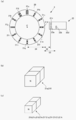
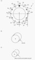
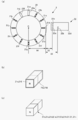
- (A) is a schematic diagram of the crank rotation angle detection sensor of FIG. 1
- (b) is a perspective view of a first magnet
- (c) is a perspective view of a second magnet.
- It is a schematic diagram showing the use condition of a crank rotation angle detection sensor.
- It is a figure showing the attachment condition of the rotation direction component detection sensor of FIG. 1, and a radial direction component detection sensor.
- (A) is a figure showing a mode that a rotation direction distortion sensor unit is affixed on a crankshaft
- (b) is a figure showing a mode that a radial direction distortion sensor unit is affixed on a crankshaft. It is an external view of the cycle computer of FIG.
- It is an electrical block diagram of a pedaling monitor.
- (A) is an electrical block diagram of the right foot unit
- (b) is an electrical block diagram of the left foot unit.
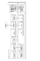
- It is a control block diagram of a pedaling monitor.
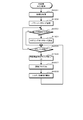
- It is a flowchart which shows the main process for left legs.
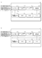
- (A) is a flowchart showing a left foot timer interrupt process in the power meter mode
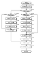
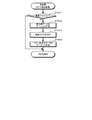
- (b) is a flowchart showing a left foot timer interrupt process in the pedaling monitor mode. It is a flowchart which shows the main process for right feet. It is a flowchart which shows the crank rotation angle detection signal interruption process for right feet. It is a flowchart which shows a left leg data reception interruption process. It is a flowchart which shows the timer interruption process for right feet in power meter mode. It is a flowchart which shows the timer interruption process for right feet in pedaling monitor mode.
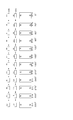
- (A) is a figure showing the rotation angle determination table for right legs
- (b) is a figure showing the rotation angle determination table for left legs.
- FIG. 6 is a schematic diagram illustrating a crank rotation angle detection sensor according to Embodiment 2.
- FIG. 10 is a schematic diagram illustrating a crank rotation angle detection sensor according to Embodiment 3.
- FIG. 10 is a schematic diagram illustrating a crank rotation angle detection sensor according to Embodiment 4.
- FIG. 10 is a schematic diagram illustrating a crank rotation angle detection sensor according to a fifth embodiment. It is a schematic diagram showing the crank rotation angle detection sensor in other embodiment.
- FIG. 1A is a side view showing a state in which a pedaling monitor 100 that calculates and displays pedal action force by pedaling of each foot for each predetermined crank rotation angle and is attached to the bicycle B is shown in FIG.
- FIG. 2 is a front view showing a state where the pedaling monitor 100 is attached to the bicycle B.
- the bicycle B has a vehicle body frame B1 and two wheels B2 (front wheel B21 and rear wheel B22) that support the frame B1 movably by being pivotally supported by the frame B1 before and after the bicycle B.
- the driving mechanism B3 transmits a propulsive force for propelling the bicycle B to the rear wheel B22, the handle B4 for the driver to steer, and the saddle B5 for the driver to sit on.
- the drive mechanism B3 has a rotation shaft (crank shaft) at one end, and the rotation shaft is rotatably supported at the other end of the crank B31.
- a pedal B32 that receives force from the driver, etc., a chainring B34 that is connected to the crank B31 with the crankshaft at the one end of the crank B31 as a common rotating shaft, and rotates integrally with the crank B1, and
- a pedal B32 By connecting to a rear sprocket (not shown) arranged so as to rotate integrally with the rear wheel B22 using the rotation axis of the rear wheel B22 as a common rotation axis, a pedal B32 such as a pedal depression force is provided.
- a chain B33 that transmits a force acting on the rear wheel (hereinafter referred to as “pedal acting force”) to the rear wheel B22 via the crank B31.
- the crank B31 has a right crankshaft B311 disposed on the right side facing the traveling direction of the bicycle B and a left crankshaft B312 disposed on the left side facing the traveling direction of the bicycle B, and these left and right crankshafts B311. , B312 are fixed at a point-symmetrical position with the crankshaft as a symmetric point.
- the pedal B32 is also a right pedal B321 that is rotatably supported by a right pedal shaft (not shown) attached to the tip of the right crankshaft B311 and a left pedal attached to the tip of the left crankshaft B312. And a left pedal B322 rotatably supported by a shaft (not shown).
- the right crankshaft B311 and the left crankshaft B312 and the right pedal B321 and the left pedal B322 have the same shape and structure.
- the pedaling monitor 100 is a crank rotation angle detection sensor 2 that detects the rotation angle of the crank B31, and a rotation that detects the magnitude of the rotation direction component of the crank acting force B31 (hereinafter referred to as “pedal acting force rotation direction component”).
- Directional component detection sensor 3 a radial direction for detecting the magnitude of a radial component (or radial direction of rotation of the crank B31) component (hereinafter referred to as “pedal operational force radial component”) of the pedal acting force as a center.
- the cycle computer 1 Right foot unit 6 for credit, left foot unit 7, and comprises a cycle computer 1 for display of the pedal force acting at a given crank angle.
- the sensors 2 to 5 and the units 6 to 7 are connected by wire. Further, the cycle computer 1, the right foot unit 6, and the left foot unit 7 include a transmitter (not shown) and are connected wirelessly.
- the crank rotation angle is expressed with reference to the right crankshaft B311. That is, when the right crankshaft B311 is positioned in the 12 o'clock direction (the tip is directed upward), the crank rotation angle is “0 °”.
- the crank rotation angle detection sensor 2 indicates the crank rotation angle “90 °” when the right crankshaft B311 indicates the direction of 3 o'clock (the front end faces forward), and the right crankshaft B311 indicates the direction of 9 o'clock.
- the crank rotation angle “270 °” is indicated.
- the range of the crank rotation angle ( ⁇ ) detected by the crank rotation angle detection sensor 2 is 0 ° or more and less than 360 ° (0 ⁇ ⁇ ⁇ 360 °), and the right crankshaft B311 is rotated from the 12 o'clock direction.
- the direction of rotation around is the “+” direction.
- the crank rotation angle detection sensor 2 includes an annular frame-shaped member 20 and a magnet group 21 including a plurality of magnets fixed to the surface of the frame-shaped member 20 at a predetermined interval. Magnets 21a and 21b) and a magnetic sensor 22.
- the frame-shaped member 20 to which the magnet group 21 is fixed has an annular shape with an outer diameter of 54 mm and an inner diameter of 44 mm, and the magnet group 21 faces the crank B31 with the center C of the frame-shaped member 20 and the crankshaft aligned. In this way, it is fixed to the side surface of the frame B1.
- the magnetic sensor 22 is fixed to the chain ring B34 and rotates together with the crank B31.
- the magnet group 21 is composed of twelve magnets 21a to 21l, and is arranged at 30 ° intervals with the center C of the annular frame-shaped member 20 as the center.
- the magnets 21a and 21l are composed of neodymium magnets having very strong magnetic force and coercive force.
- the magnets 21a and 21l are composed of two first neodymium magnets (3 mm ⁇ 3 mm ⁇ 3 mm) in series (both N poles are stacked on the same straight line in the same direction), and the other magnets 21b.
- the magnet 21k includes two second neodymium magnets (2 mm ⁇ 2 mm ⁇ 3 mm) having a smaller magnetic force than the first neodymium magnet. That is, the magnet group 21 includes two types of magnets having different magnetic forces.
- the magnet 21a and the magnet 21b are arranged in a state where the respective central axes coincide with the radial direction of the frame-shaped member 20.
- the magnets whose north pole faces outward and the magnets facing inward (center side) are alternately arranged in the circumferential direction of the frame-shaped member 20.
- the N poles of the magnet 21a, the magnet 21c, the magnet 21e, the magnet 21g, the magnet 21i, and the magnet 21k face outward in the radial direction (radial direction) of the frame-shaped member 20, and the magnet 21b, the magnet 21d, the magnet 21f, The north poles of the magnet 21h, the magnet 21j, and the magnet 21l face the radially inner side (center) of the frame-shaped member 20. Furthermore, the distance L4 between the radially outer ends of the magnets 21a to 21l and the center C of the frame-shaped member 20 is the same.
- the magnetic sensor 22 includes a first element portion 22a, a second element portion 22b, and a third element portion 22c accommodated in a case 22d.
- the first element portion 22a and the second element portion 22b detect magnetic lines of force (magnetic field) in a predetermined direction (horizontal leftward in FIG. 2A), and detect magnetic lines of force opposite to the detection direction (N pole) Hi is output when the opposing magnet is detected), and Lo is output when the magnetic lines of force in the same direction as the detection direction are detected (when the magnet facing the south pole is detected). Note that the first element portion 22a and the second element portion 22b maintain the output state when a magnetic field line having a predetermined strength is not detected.
- the crank rotation angle detection sensor 2 When the crank rotation angle detection sensor 2 is in use (when the frame member 20 and the magnetic sensor 22 are appropriately fixed to the bicycle B), when viewed from the side of the bicycle B, the first element portion 22a and the second element The portion 22b is arranged on the outer side in the radial direction of the frame-shaped member 20, that is, at a position farther from the center C of the frame-shaped member 20 than the magnets 21a to 21l. Further, the detection directions of the element portions 22a and 22b are the same, and the center C of the frame-shaped member 20 is located on each detection direction. The first element portion 22a is disposed closer to the center C of the frame-shaped member 20 than the second element portion 22b, and is closer to the outer tips of the magnets 21a to 21l passing in the detection direction.
- the first element portion 22a is disposed at a position 9.0 mm away from the outer tip of the nearest magnet (the one closer to the intersection of the magnet movement path and the detection direction), and the second element portion 22b is the most It is arranged at a position 13.5 mm away from the outer tip of the adjacent magnet.
- the crank rotation angle ( ⁇ ) “0 °” (when the right crankshaft B311 indicates 12:00)
- the second element portion 22b detects the magnet 21a (the magnet 21a is detected by the second element portion 22).
- the frame-shaped member 20 and the magnetic sensor 22 are fixed to the bicycle B so as to be positioned on the detection direction of the bicycle B.
- the magnetic sensor 22 is provided with a third element part 22c having lower power consumption than the first element part 22a and the second element part 22b.
- the third element portion 22c is provided in the vicinity of the first element portion 22a, and activates the system of the unit 6 when any of the magnets 21a to 21l is detected.
- the first element portion 22a of the magnetic sensor 22 passes in front of the magnets 21a to 21l. Switch the output to Hi or Lo. Similarly, every time the second element portion 22b of the magnetic sensor 22 passes in front of the magnets 21a and 21l, the output is switched between Hi and Lo.
- the “Hi” or “Lo” output from the first element portion 22a detects that the crank B31 has rotated 30 ° (hereinafter referred to as “interval angle detection signal”).
- the crank rotation angle ( ⁇ ) can be detected at intervals of 0 ° to 30 °.
- the Hi output from the second element portion 22b becomes Lo when passing in front of the magnet 21l arranged in the opposite direction with the same magnetic force. That is, it is reset. Therefore, the crank rotation angle can be detected continuously. Therefore, “Lo” output from the second element portion 22b is hereinafter referred to as “reset signal”.
- the reference magnet 21a is a second magnet.
- the second element portion 22b can detect the reference magnet 21a when the element portion 22b is closest to the second element portion 22b in the detection direction of the element portion 22b (hereinafter referred to as “second detection direction”).
- the first element part 22a When the magnet 21l is closest to the first element part 22a in the detection direction of the first element part 22a (hereinafter referred to as “first detection direction”), the first element part 22a can detect the magnets 21b to 21k, It is desirable that the first element portion 22a cannot detect the reference magnet 21a when the reference magnet 21a is farthest from the first element portion 22a in the first detection direction.
- the center C is arranged on the central axis of each of the magnets 21a to 21l, and the directions of the N poles are alternately switched in the circumferential direction.
- the magnets 21a to 21l are arranged at predetermined intervals, and when the magnets 21a to 21l and the element portions 22a and 22b are closest to each other, the magnets 21a to 21l
- the central axis and the detection direction of each element part 22a, 22b correspond.
- the detection accuracy of the crank rotation angle by the crank rotation angle detection sensor 2 is improved. This is because the magnitude of the relative magnetic field with respect to each element part 22a, 22b increases.
- the ratio of the lengths of the magnets 21a to 21l in the central axis direction can be increased. Further, a bobbin can be attached to the magnets 21a to 21l.
- the magnets 21a to 21l are installed on the frame member 20 so that the central axes of the magnets 21a to 21l and the surface of the frame member 20 are parallel to each other.
- the thickness of the frame-shaped member 20 can be suppressed with respect to the magnet having the same thickness, and the cost can be suppressed.
- the rotational direction component detection sensor 3 includes a sensor unit 3a composed of two strain sensors (hereinafter referred to as “rotational direction strain sensor unit 3”). As shown in FIG. 1 and FIG. A right rotation direction component detection sensor 31 and a left crankshaft B312 that are attached to the front surface (the surface that faces the traveling direction when the crankshafts B311 and B312 indicate the 6 o'clock direction). Left rotation direction component detection sensor 32).
- the rotation direction component detection sensor 3 includes a rotation direction distortion detection circuit connected to each terminal of a distortion sensor constituting a rotation direction distortion sensor unit 3a (not shown), and rotation direction component control for comprehensively controlling the sensor 3. Part.
- the strain sensors constituting the rotational direction strain sensor units 31a and 32a are bonded in a state of being orthogonal to each other on the front surfaces of the crankshafts B311 and B312.
- the rotation direction distortion detection circuit amplifies and adjusts the output of each distortion sensor, and transmits information indicating a uniform distortion amount (hereinafter referred to as “rotation direction distortion information”) to the rotation direction component control unit.
- the rotational direction component control part of each sensor 31 and 32 is based on the rotational direction distortion amount information transmitted by each rotational direction distortion detection circuit, and the rotational direction component Fx (N) of the crank acting force from the following number (1).
- a rotation direction component detection signal corresponding to each pedal acting force rotation direction component Fx is transmitted to each unit 6, 7. [Number (1)]
- Fx mg (X ⁇ Xz) / (Xc ⁇ Xz)
- m represents mass
- g represents gravitational acceleration
- X represents the amount of strain detected by the rotational direction strain detection circuit
- Xc represents that the crankshaft B31 is held in a horizontal state.
- Xz is the amount of distortion of the front of the crankshaft B31 when the crankshaft B31 is unloaded.
- Xc and Xz are acquired, for example, by attaching the sensor unit 3a to the front surface of the crankshaft B31 and calibrating it before using the sensor 3.
- the radial direction component detection sensor 4 includes a sensor unit 4a composed of two strain sensors (hereinafter referred to as “radial direction strain sensor unit 4”), and as shown in FIGS. 1 and 4, the outer surface of the crankshaft B31.
- the radial direction component detection sensor 4 is attached to (a right radial direction component detection sensor 41 attached to the right crankshaft B311 and a left radial direction component detection sensor 42 attached to the left crankshaft B312).
- the radial direction component detection sensor 4 includes a radial direction distortion detection circuit connected to each terminal of a strain sensor constituting a radial direction strain sensor unit 4a (not shown), and radial direction component control for comprehensively controlling the sensor 4. Part.
- the strain sensors constituting the radial strain sensor units 41a and 42a are bonded to each other on the outer surfaces of the crankshafts B311 and B312 so as to be orthogonal to each other.
- the radial direction distortion detection circuit amplifies and adjusts the output of each strain sensor, and controls information indicating the unified distortion amount detected by the sensor unit 4a (hereinafter referred to as “radial direction distortion information”).
- m represents mass
- g represents gravitational acceleration
- Y represents the amount of strain detected by the radial strain detection circuit
- Yu represents the pedal B32 located at the bottom dead center.
- Yz is the amount of distortion of the outer surface of the crankshaft B31 when the crankshaft B31 is unloaded.
- Yu and Yz are acquired, for example, by attaching the sensor unit 4a to the outer surface of the crankshaft B31 and calibrating it before using the sensor 4.
- the cadence detection sensor 5 is composed of, for example, a cadence sensor composed of a magnet fixed to the left crankshaft B312 and a magnet detector mounted at a predetermined position of the frame B1, and the magnet is detected per unit time (one minute).
- the number of rotations of the crank B31 per unit time is detected by detecting the number n (rpm) of passing the front of the magnet detector. From this sensor 5, a cadence detection signal corresponding to the rotation speed of the crank B 31 per unit time is transmitted to each unit 6, 7.
- the pedaling monitor 100 is based on the right rotational direction component detection signal transmitted from the right rotational direction component detection sensor 31 and the right radial direction component detection signal transmitted from the right radial direction component detection sensor 41.
- the left foot unit 7 for calculating the torque, power, etc. of the left foot and the cycle computer 1 for visualizing these calculation results comprehensively or in combination based on the calculation results of the units 6 and 7. Is done.
- the cycle computer 1 is fixed to the bicycle B via a predetermined mounting member 8 that can be attached to and detached from the handle B4 of the bicycle B.
- the cycle computer 1 includes an input unit 11 for inputting predetermined information, a display unit 12 for displaying predetermined information, and a control unit 13 having an arithmetic circuit for executing predetermined processing related to pedaling (see FIG. 7). ), And a housing 14 that houses the input unit 11, the display unit 12, and the control unit 13.
- the input unit 11 includes three operable operation units 11a, 11b, and 11c that are juxtaposed in a state of protruding from the upper surface of the housing 14, and a power source that can be slid to perform ON / OFF switching of power supply.
- a switch 11d is provided.
- the input unit 11 includes an input control circuit 11e that relays an input signal associated with the operation of the operation units 11a to 11c and the power switch 11d as control information to the control unit 13.
- Each operation unit 11a, 11c has a button structure, and 11b has a cross key structure.
- the input control circuit 11e converts it into control information corresponding to the operation and transmits it to the control unit 13. Accordingly, the driver can input a plurality of types of input of the operation units 11a to 11c, such as input of specific information regarding the driver and bicycle and start / end of measurement, depending on the combination of operations.
- the display unit 12 includes, for example, a liquid crystal panel 12a for displaying torque, power, etc. for each predetermined crank rotation angle for each foot, and a display for performing display control of the liquid crystal panel 12a according to information to be displayed. And a control circuit 12e.
- the input unit 11 and the display unit 12 can be integrated by using the liquid crystal panel 12a as a touch panel.
- the control unit 13 of the cycle computer 1 includes a CPU 13a, ROM 13b, RAM 13c, oscillation circuit 13d, recording medium I / F 13e, communication I / F 13f, sensor I / F 13g, right foot unit transmission I / F 13h, right foot unit.
- the reception I / F 13i, the left foot unit transmission I / F 13j, and the left foot unit reception I / F 13k are connected by a bus 13l.
- the CPU 13a controls basic operations as a cycle computer including display of predetermined parameters related to pedaling based on a program stored in advance in the ROM 13b.
- the ROM 13b stores in advance a program code for executing basic processing as a cycle computer executed by the CPU 13a.
- the RAM 13c functions as a working area for data and the like in arithmetic processing performed when the CPU 13a executes basic processing as a cycle computer.
- the oscillation circuit 13d includes a crystal resonator as a clock oscillator, and outputs a pulse signal to the CPU 13a at a predetermined cycle by counting generated clocks.
- the recording medium I / F 13e is an interface for recording predetermined information on a recording medium such as a memory card.
- the communication I / F 13f is an interface for transmitting / receiving data to / from an external processing device such as a mobile terminal such as a mobile phone or a PC installed at home or the like.
- the sensor I / F 13g is an interface for taking in various detection signals transmitted from a predetermined sensor.
- the right foot unit transmission I / F 13 h is an interface for transmitting a mode conversion signal to the right foot unit 6.
- the right foot unit receiving I / F 13 i is an interface for receiving data from the right foot unit 6.
- the left foot unit transmission I / F 13 j is an interface for transmitting a mode conversion signal to the left foot unit 7.
- the left foot unit receiving I / F 13 k is an interface for receiving data from the left foot unit 7.
- the input unit 11, the display unit 12, and the control unit 13 described above are configured to transmit and receive necessary information data via the bus 13l.
- the right foot unit 6 is attached to the right crank B311 of the bicycle B.
- the right foot unit 6 includes a control unit 61 that includes a calculation circuit that executes predetermined processing related to calculation of torque and power by pedaling with the right foot, and a housing (case) 62 that houses the control unit 61.
- the left foot unit 7 is attached to the left crank B312 of the bicycle B, and includes a control unit 71 including an arithmetic circuit for executing predetermined processing relating to calculation of torque and power by pedaling on the left foot, and control.
- a housing 72 that accommodates the portion 71 is included.
- the control unit 71 of the left foot unit 7 includes a CPU 71a, a ROM 71b, a RAM 71c, an oscillation circuit 71d, a sensor I / F 71e, a siphon receiving I / F 71f, a siphon transmitting I / F 71g,
- the right foot unit transmission I / F 71h is connected to each other by a bus 71j.
- the CPU 71a controls the basic operation of the left foot unit 7 including calculation of torque and power by pedaling on the left foot based on a program stored in advance in the ROM 13b.
- the ROM 71b stores in advance program codes for executing basic processing as a cycle computer executed by the CPU 71a.
- the RAM 71c functions as a working area for data and the like in arithmetic processing performed when the CPU 71a executes basic processing as the left foot unit 7.
- the oscillation circuit 71d includes a crystal resonator as a clock oscillator, and counts a clock generated according to a function mode (pedaling monitor mode / power meter mode) set when the power is turned on at a predetermined cycle. A pulse signal is output to the CPU 71a.
- the oscillation circuit 71d outputs pulse signals at intervals of 6.05 Hz in the pedaling monitor mode, and outputs pulse signals at intervals of 4.10 Hz in the power meter mode.
- the sensor I / F 71e is an interface for taking in various detection signals transmitted from the crank rotation angle detection sensor 2, the left rotation direction component detection sensor 32, the left radial direction component detection sensor 42, and the cadence detection sensor 5 described above. It is.
- the reciprocal I / F 71 f is an interface for receiving a mode switching signal transmitted from the cycle computer 1.
- the sicon transmission I / F 71g is an interface for transmitting various calculation value data transmitted to the cycle computer 1 in the pedaling monitor mode described later.
- the right foot unit transmission I / F 71h is an interface for transmitting various calculation value data transmitted to the cycle computer 1 in the power meter mode.
- the control unit 61 of the right foot unit 6 includes a CPU 61a, a ROM 61b, a RAM 61c, an oscillation circuit 61d, a sensor I / F 61e, a silicon reception I / F 61f, a silicon transmission I / F 61g,
- the left foot unit receiving I / F 61h is connected to each other by a bus 61j.
- the CPU 61a based on a program stored in the ROM 61b in advance, generates torque and power by pedaling with the right foot, and overall torque and power by pedaling with both feet, cumulative torque, cumulative power, and contribution to the right foot.
- the basic operation of the right foot unit 6 including the calculation of is controlled.
- program codes for executing basic processing as the right foot unit 6 executed by the CPU 61a are stored in advance.
- the RAM 61c functions as a working area for data and the like in arithmetic processing performed when the CPU 61a executes basic processing as the right foot unit 6.
- the oscillation circuit 61d includes a crystal resonator as a clock oscillator, and counts a clock generated according to a function mode (pedaling monitor mode / power meter mode) set when the power is turned on. A pulse signal is output to the CPU 61a.
- the oscillation circuit 61d outputs pulse signals at intervals of 6.00 Hz in the pedaling monitor mode, and outputs pulse signals at intervals of 4.00 Hz in the power meter mode.
- the reciprocal I / F 61e is an interface for receiving a mode switching signal transmitted from the cycle computer 1.
- the sensor I / F 61f is an interface for capturing various detection signals transmitted from the crank rotation angle detection sensor 2, the right rotation direction component detection sensor 31, the right radial direction component detection sensor 41, and the cadence detection sensor 5 described above. It is.
- the Saikon transmission I / F 61 f is an interface for transmitting various calculation value data transmitted to the cycle computer 1.
- the left foot unit receiving I / F 61g is an interface for receiving various calculation value data transmitted from the left foot unit 7 in the power meter mode.
- FIG. 9 is a block diagram showing a controllable (or functional) configuration of the pedaling monitor 100 according to the embodiment of the present invention.
- the left foot unit 7 of the pedaling monitor 100 includes a measurement data receiving unit 7A, a mode switching signal receiving unit 7B, a mode switching unit 7C, a frequency switching unit 7D, a frequency transmitting unit 7E, a calculating unit 7F, and a left foot data transmitting unit 7G.
- the measurement data receiving unit 7A outputs a crank rotation angle detection signal output from the crank rotation angle detection sensor 2, a left rotation direction component detection signal output from the left rotation direction component detection sensor 32, and a left radial direction component detection sensor 42.
- the left radiation direction component detection signal and the cadence detection signal output from the cadence detection sensor 5 are received and stored in each storage area of the RAM 71c.
- the mode switching signal receiving unit 7B receives the mode switching signal output from the cycle computer 1.
- the mode switching unit 7C turns on the pedaling mode flag in the cycle mode flag storage area of the RAM 71c and switches from the power meter mode which is the initial setting to the pedaling mode. Switch.
- the frequency switching unit 7D sets the frequency of the pulse signal output from the frequency transmission unit 7E (oscillation circuit 71d), which will be described later, to the CPU 71a, from the initial setting of 4.10 Hz to 6. Switch to 05 Hz.
- the frequency transmitter 7E has a crystal resonator as a clock oscillator, and counts the clock generated according to the mode (pedaling monitor mode / power meter mode) set when the power is turned on. A pulse signal is output to the CPU 71a.
- the calculation unit 7F Based on the crank rotation angle ( ⁇ ) stored in the RAM 71c, the rotation direction component (N) of the pedal action force relating to the left foot, and the radial direction component (N) of the pedal action force relating to the left foot, the calculation unit 7F The torque and power (energy consumption) related to pedaling are calculated and stored in the left torque storage area and the left power storage area of the RAM 71c.
- the left foot data transmission unit 7G transmits the left torque data and the left work rate data based on the function mode (power meter mode / pedaling mode).
- the left foot data transmission unit 7G transmits the left torque data and the left work rate data to the right foot unit 6 in the power meter mode and to the cycle computer 1 in the pedaling mode.
- the right foot unit 6 of the pedaling monitor 100 includes a measurement data receiving unit 6A, a mode switching signal receiving unit 6B, a mode switching unit 6C, a frequency transmitting unit 6E, a calculating unit 6F, a left foot data receiving unit 6G, and a right foot data transmitting unit 6H.
- the measurement data receiving unit 6A is output from the crank rotation angle detection signal output from the crank rotation angle detection sensor 2, the rotation direction component detection signal output from the right rotation direction component detection sensor 31, and the right radial direction component detection sensor 41. And a cadence detection signal output from the cadence detection sensor 5 and stored in each storage area of the RAM 61c.
- the mode switching signal receiving unit 6B receives the mode switching signal output from the cycle computer 1.
- the mode switching unit 6C turns on the pedaling mode flag in the cycle mode flag storage area of the RAM 61c and switches from the power meter mode which is the initial setting to the pedaling mode. Switch.
- the frequency switching unit 6D changes the frequency of the pulse signal output from the frequency transmission unit 6E (oscillation circuit 61d), which will be described later, to the CPU 61a from the initial setting of 4.00 Hz to 6 Switch to .00Hz.
- the frequency transmitter 6E includes a crystal resonator as a clock oscillator, and counts a clock generated regardless of a function mode (pedaling monitor mode / power meter mode) set when the power is turned on. To output a pulse signal to the CPU 61a.
- the calculation unit 6F Based on the crank rotation angle ( ⁇ ), the rotation direction component (N) of the pedal action force related to the right foot, and the radial direction component (N) of the pedal action force related to the right foot stored in the RAM 61c, the calculation unit 6F The torque and the power related to pedaling are calculated and stored in the right torque storage area and the right power storage area of the RAM 63c.
- the left foot data receiving unit 6G receives the left torque data and the left work rate data transmitted from the left foot unit 7 in the power meter mode, and stores them in the left torque data storage region and the left work rate data storage region of the RAM 61c.
- the right foot data transmission unit 6H transmits predetermined calculation value data to the cycle computer 1 regardless of the mode type.
- step S1001 the CPU 71a performs an initialization process.
- the CPU 71a reads a startup program from the ROM 71b and initializes a predetermined storage area of the RAM 71c.
- step S1002 the CPU 71a sets the function mode to the power meter mode. That is, the power meter mode is set as the initial setting of the function mode. Specifically, a power meter flag (for example, “00H”) is turned on in the function mode flag storage area of the RAM 71c. Then, the CPU 71a determines whether or not a mode switching signal is output from the cycle computer 1 in step S1003. If the CPU 71a determines that the mode switching signal is not output, the process proceeds to step S1005. If the CPU 71a determines that the mode switching signal is output, the pedaling monitor flag (for example, “01H”) is stored in the mode flag of the RAM 71c in step S1004. By turning on the area, the function mode is set to the pedaling monitor mode.
- the pedaling monitor flag for example, “01H
- step S1006 the CPU 71a calculates the average value of torque and the average value of the power related to the left foot in one rotation of the crank B31, and calculates the left torque data indicating the average value of the torque and the left value indicating the average value of the power.
- the work rate data is stored in the left torque data storage region and the left work rate data storage region of the RAM 71c, respectively.
- step S1007 the torque update flag and the work rate are stored in the torque update flag storage region and the work rate update flag storage region of the RAM 71c, respectively. Turn on the update flag. Thereafter, steps S1003 to S1007 are repeated until a predetermined interrupt process is performed.
- the calculation method of the average value of torque concerning the left foot and the average value of power is not particularly limited.
- the left foot unit 7 receives the measurement data (detection signal) transmitted from the left rotation direction component detection sensor 32, the left radial direction component detection sensor 42, and the cadence detection sensor 5 at predetermined time intervals. And stored in a predetermined area of the RAM 71c. And CPU71a calculates the average value of the torque which concerns on a left leg, and the average value of work power using these data. Further, necessary data other than the measurement data such as the crank length L1 is acquired by appropriate processing such as input using the input unit 11 of the cycle computer 1.
- crank rotation angle detection signal interrupt processing Next, the left foot crank rotation angle detection signal interruption process will be described with reference to FIG.
- the crank rotation angle detection signal including the reference angle detection signal or the interval angle detection signal is output to the left foot unit 7 by the crank rotation angle detection sensor 2, and the following left foot crank rotation angle detection signal interrupt processing is executed. Is done.
- step S2001 the CPU 71a determines whether or not the signal is a reference angle detection signal. If the CPU 71a determines that the signal is a reference angle detection signal, the CPU 71a resets the rotation angle determination counter provided in the RAM 71c (sets the counter value to "0") in step S2002, and stores the pedal action force data in the RAM 71c in step S2003. Clear the area and end the interrupt process.
- the CPU 71a determines that it is not a reference angle detection signal, that is, an interval angle detection signal, the CPU 71a updates it by adding “1” to the counter value of the rotation angle determination counter in step S2004, and stores it in the ROM 71b in step S2005.
- the current crank rotation angle is determined using the rotation angle determination table.
- the crank rotation angle detection sensor 2 has the crank B31. Since the interval angle detection signal is transmitted to the left foot unit 7 every rotation of 30 ° (since one rotation of the crank B31 is divided into 12), the counter value range is “1” to “12”.
- crank rotation angle increases by 30 °.
- the right crankshaft B311 faces the 12 o'clock direction
- the left crankshaft B312 faces the 6 o'clock direction. That is, the right crankshaft B311 and the left crankshaft B312 are shifted by 180 °. Therefore, when the counter value is “7”, the crank rotation angle ( ⁇ ) of the left crankshaft B312 is “0 °”.
- the pedal action force data indicating the pedal action force is stored in the pedal action force data storage area of the RAM 71c, and the interruption process is terminated.
- the direction of the pedal action force F (for example, the angle with respect to the ground surface) is determined using the crank rotation angle ( ⁇ ). ⁇ ) can also be calculated, and pedal operation force data indicating the crank rotation angle ( ⁇ ), the pedal operation force (F), and the direction ( ⁇ ) of the pedal operation force can be stored. Further, as will be described later, pedal action force data relating to one rotation of the crank B31 is collectively transmitted when the crank B31 makes one rotation. Therefore, it is assumed that an area for storing data for at least one rotation is secured in the pedal action force data storage area of the RAM 71c (for example, at least twelve pedal action force data can be stored). .
- the clock interrupt is generated at predetermined intervals by the oscillation circuit 71d provided in the left foot unit 7, whereby the following timer interrupt process is executed.
- the CPU 71a receives the pulse signal from the oscillation circuit 71d, the CPU 71a checks the function mode flag storage area. If the power mode flag is ON, the CPU 71a performs steps S3001 to S3003, and the pedaling monitor mode flag is ON. Steps S3501 to S3504 are performed. As described above, in the power meter mode, pulse signals are output to the CPU 71a at intervals of 4.10 Hz. Therefore, the left foot timer interrupt processing in the power meter mode is performed at intervals of 4.10 Hz.
- step S3001 the CPU 71a determines whether or not the update flag is turned on in the update flag storage area of the RAM 71c.
- the CPU 71a transmits the left torque data and the left work rate data stored in the RAM 71c to the right foot unit 6 in step S3002, and turns off the update flag in step S3003.
- the left foot timer interruption process is terminated. If the CPU 71a determines that the update flag is not turned on, the CPU 71a ends the left foot timer interruption process as it is.
- step S3501 the CPU 71a determines whether or not the update flag is turned on in the update flag storage area of the RAM 71c. When determining that the update flag is turned on, the CPU 71a transmits the left torque data and the left power data stored in the RAM 71c to the cycle computer 1 in step S3502, and turns off the update flag in step S3503.
- step S3504 the CPU 71a obtains a plurality of pedal action force data (for one rotation of the crank B31) associated with a predetermined crank rotation angle stored in the pedal action force data storage area of the RAM 71c. This is transmitted to the cycle computer 1 and the left foot timer interruption process is terminated. If the CPU 71a determines in step S3501 that the update flag is not turned on, the CPU 71a directly ends the left foot timer interrupt process.
- step S4001 the CPU 61a performs initialization processing.
- the CPU 61a reads the activation program from the ROM 61b and initializes a predetermined storage area of the RAM 61c.
- step S4002 the CPU 61a sets the function mode to the power meter mode. That is, the power meter mode is set as the initial setting of the function mode. Specifically, a power meter flag (for example, “00H”) is turned on in the function mode flag storage area of the RAM 61c. Then, the CPU 61a determines whether or not a mode switching signal is output from the cycle computer 1 in step S4003. If the CPU 61a determines that the mode switching signal has not been output, the process proceeds to step S4005. If the CPU 61a determines that the mode switching signal has been output, in step S4004, the pedaling monitor flag (eg, “01H”) is stored in the mode flag stored in the RAM 61c. By turning on the area, the function mode is set to the pedaling monitor mode.
- a power meter flag for example, “00H”
- the pedaling monitor flag eg, “01H”
- step S4006 the CPU 61a calculates an average value of torque and an average value of the work rate for the right foot in one rotation of the crank B31, and right torque data indicating the average value of the torque and a right value indicating the average value of the work rate.
- the work rate data is stored in the right torque data storage region and the right work rate data storage region of the RAM 61c, respectively.
- step S4007 the torque update flag and the work rate are stored in the torque update flag storage region and the work rate update flag storage region of the RAM 61c, respectively. Turn on the update flag. Thereafter, steps S4003 to S4007 are repeated until a predetermined interrupt process is performed.
- the calculation method of the average value of the torque concerning the right foot and the average value of the power is not particularly limited.
- the right foot unit 6 receives measurement data (detection signals) transmitted from the right rotation direction component detection sensor 31, the right radial direction component detection sensor 41, and the cadence detection sensor 5 at predetermined time intervals. And stored in a predetermined area of the RAM 61c. And CPU61a calculates the average value of the torque which concerns on a right leg, and the average value of work power using these data. Further, necessary data other than the measurement data such as the crank length L1 is acquired by appropriate processing such as input using the input unit 11 of the cycle computer 1.
- crank rotation angle detection signal interrupt processing Next, the right foot crank rotation angle detection signal interruption process will be described with reference to FIG.
- the crank rotation angle detection signal which is a reference angle detection signal or an interval angle detection signal, is output to the right foot unit 6 by the crank rotation angle detection sensor 2, whereby the following timer interruption process is executed.
- step S5001 the CPU 61a determines whether or not the signal is a reference angle detection signal. If the CPU 61a determines that the signal is the reference angle detection signal, in step S5002, the CPU 61a resets the rotation angle determination counter provided in the RAM 61c (sets the counter value to "0"), and in step S5003, the pedal operation force of the RAM 61c described later. The data storage area is cleared, and the interrupt process ends.
- the CPU 61a determines that it is not the reference angle detection signal, that is, the interval angle detection signal, the CPU 61a updates the counter value of the rotation angle determination counter by adding “1” in step S5004, and stores it in the ROM 61b in step S5005.
- the current crank rotation angle is determined using the rotation angle determination table.
- the pedal action force data indicating the action force is stored in the pedal action force data storage area of the RAM 71c, and the interrupt process is terminated.
- the direction of the pedal action force F (for example, the angle with respect to the ground surface) is determined using the crank rotational angle ( ⁇ ).
- ⁇ ) can also be calculated, and pedal operation force data indicating the crank rotation angle ( ⁇ ), the pedal operation force (F), and the direction ( ⁇ ) of the pedal operation force can be stored.
- pedal action force data relating to one rotation of the crank B31 is collectively transmitted when the crank B31 makes one rotation. Therefore, it is assumed that an area for storing data for at least one rotation is secured in the pedal action force data storage area of the RAM 61c (for example, at least twelve pedal action force data can be stored). .
- the clock interrupt is generated at predetermined intervals by the oscillation circuit 61d provided in the right foot unit 6, whereby the following timer interrupt process is executed.
- the CPU 61a checks the function mode flag storage area. If the power mode flag is ON, the CPU 61a performs steps S7001 to S7016, and the pedaling monitor mode flag is ON. Steps S7501 to S7504 are performed. As described above, in the power meter mode, pulse signals are output to the CPU 61a at 4.0 Hz intervals. Therefore, the right foot timer interrupt processing in the power meter mode is performed at 4.00 Hz intervals.
- step S7003 the CPU 61a determines whether or not the torque update flag is turned on in the torque update flag storage area of the RAM 61c. If the CPU 61a determines that the torque update flag is not ON, it moves the process to step S7007, and if it determines that the torque update flag is ON, it moves the process to step S7004.
- step S7004 the CPU 61a indicates the left torque indicated by the left torque data transmitted from the left foot unit 7 and stored in the left torque data storage area, and the right torque data stored in the right torque data storage area.
- the total torque (by both feet) is calculated by adding the right torque, and the total torque data is stored in the total torque data storage area of the RAM 61c.
- the CPU 61a calculates the accumulated torque in step S7005. For example, the CPU 61a calculates the cumulative torque for a predetermined period, and stores cumulative torque data indicating the cumulative torque in the cumulative torque storage area of the RAM 61c. Here, the CPU 61a calculates a new accumulated torque by adding the current total torque to the previous accumulated torque stored in the accumulated torque storage area, and stores the accumulated torque data in the accumulated torque storage area. .
- step S7006 the CPU 61a turns off the torque update flag.
- step S7007 the CPU 61a transmits the total torque data stored in the total torque data storage area and the cumulative torque data stored in the cumulative torque data storage area to the cycle computer 1. Then, the process proceeds to step S7015.
- step S7008 the CPU 61a determines whether or not the work rate update flag is turned on in the work rate update flag storage area of the RAM 61c. If the CPU 61a determines that the work rate update flag is not turned on, it moves the process to step S7013, and if it determines that the work rate update flag is turned on, it moves the process to step S7009.
- step S7009 the CPU 61a stores the left work rate indicated by the left work rate value data transmitted from the left foot unit 7 and stored in the left work rate data storage area, and the right work rate data storage area.
- the total power (by both feet) is calculated by adding the right power indicated by the right power data, and the total power data indicating the total power is stored in the total power data storage area of the RAM 61c. To do.
- step S7010 the CPU 61a calculates the right foot contribution. That is, the right CPU 61a calculates the right foot contribution, which is the ratio of the right work rate to the total work rate calculated in step S7009, and stores the right foot contribution data in the right foot contribution data storage area.
- the CPU 61a calculates the cumulative power in step S7011. For example, the CPU 61a calculates the cumulative work rate and stores cumulative work rate data indicating the cumulative work rate in the cumulative work rate storage area of the RAM 61c. Here, a new cumulative power is calculated by adding the current power to the previous cumulative power stored in the cumulative power storage area, and the cumulative power data is stored in the cumulative power storage area.
- the CPU 61a turns off the work rate update flag in step S7012, and in step S5013, the total work rate data stored in the total work rate data storage area, the right foot contribution data stored in the right foot contribution data storage area, and The accumulated power data stored in the accumulated power data storage area is transmitted to the cycle computer 1, and the process proceeds to step S7014.
- the processing content determination counter “4” is reset, in the timer interrupt processing in the power meter mode of the right foot unit 6, the work rate, the right foot contribution, and the accumulation at a rate of once every four times. It can be said that the work rate is calculated.
- the CPU 61a acquires cadence data from the cadence detection sensor 5 in step S7015, transmits the cadence data to the cycle computer 1 in step S7016, and ends the right foot timer interrupt process in the power meter mode.
- step S7501 the CPU 61a determines whether or not the update flag is turned on in the update flag storage area of the RAM 61c. If the CPU 61a determines that the update flag is ON, the CPU 61a transmits the right torque data and right work rate data stored in the RAM 61c to the cycle computer 1 in step S7502, and turns OFF the update flag in step S7503.
- step S7504 the CPU 61a obtains a plurality of pedal action force data (for one rotation of the crank B31) associated with a predetermined crank rotation angle stored in the pedal action force data storage area of the RAM 61c. This is transmitted to the cycle computer 1 and the right foot timer interruption process is terminated. If the CPU 61a determines in step S7501 that the update flag is not turned on, the CPU 61a ends the right foot timer interrupt process as it is.
- the pedaling monitor 100 including the right foot unit 6 and the left foot unit 7 separately measures the pedal acting force by the right foot and the pedal acting force by the left foot, and a predetermined crank rotation angle with respect to pedaling by each foot. Can be measured and analyzed.
- the right foot unit 6 and the left foot unit 7 are provided with a power meter mode. In the power meter mode, left torque data and left work rate data measured by the left foot unit 7 are transmitted to the right foot unit 6. The left torque and the left work rate indicated by these data are added to the right torque and the right work rate measured by the right foot unit 6 to calculate the overall torque and the overall work rate. (A predetermined standard such as “ANT”) is transmitted to the cycle computer 1.
- the right foot unit 6 and the left foot unit 7 Can be used for the cycle computer 1. Thereby, the versatility of the right foot unit 6 and the left foot unit 7 can be enhanced.
- the data transmission interval (4.00 Hz) of the right foot unit 6 and the data transmission interval (4.00 Hz) of the left foot unit 7 are different. Therefore, it is possible to suppress an increase in the period during which data cannot be received due to data collision. Furthermore, since the data transmission interval between the units 6 and 7 is shorter than the data transmission interval between the left foot unit 7 and the cycle computer 1, an incomplete overall torque and work rate (data to the cycle computer 1) It is possible to prevent the transmission of the torque measured by the left foot unit 7 to be transmitted and the total torque and work rate consisting only of the work rate.
- the power meter mode is initially set, even for a cycle computer that is not originally designed and designed to separately measure the pedal force of both feet, the right foot unit 6 and the left foot The unit 7 can be applied reliably.
- crank rotation angle detection sensor 2 shown in FIG. 19 will be described as another embodiment. This is the same as the other parts except that the shapes of the magnets 21a to 21l, the fixing position and fixing direction of the frame-like member 20, and the fixing position and fixing direction of the magnetic sensor 22 are different. Therefore, the description about the part using the same name and code
- the frame-like member 20 has an annular shape having an outer diameter of 54 mm and an inner diameter of 44 mm, as in the first embodiment.
- the frame-like member 20 is formed with cylindrical insertion holes 20a to 20l in the thickness direction in which the magnets 21a to 21l are inserted.
- the centers (central axes) of the cross-sections of the respective insertion holes 20a to 20l are arranged at 30 ° intervals on the circumference having a radius of 50 mm from the center C of the frame-shaped member 20.
- the insertion holes 20a to 20l are divided into an insertion hole 20a and an insertion hole 20l, and an insertion hole 20b to an insertion hole 20k. That is, the diameters of the insertion holes 20a and 20l are 6 mm, and the diameters of the insertion holes 20b to 20k are 4 mm.
- the magnets 21a to 21l are inserted and fixed in the insertion holes 20a to 20l. That is, the magnets 21a to 21l also have a cylindrical shape, the cross sections of the magnets 21a and 21l have a circular shape with a diameter of 6 mm, and the cross sections of the magnets 21b to 21k have a circular shape with a diameter of 4 mm. Further, N poles are formed at one end of the magnets 21a and 21b, and S poles are formed at the other end.
- the central axes of the magnets 21a to 21l fitted into the fitting holes 20a to 20l are the crank B31. It is parallel to the direction of the crankshaft. Further, the magnets 21a to 21l are alternately arranged in opposite directions, and the N pole of the reference magnet 21a faces the crank B31.
- the configuration of the magnetic sensor 22 is the same as that in the first embodiment, but the relationship with the magnets 21a to 21l when being fixed to the chain ring B34 is different from that in the first embodiment.
- the magnetic sensor 22 includes the first element portion 22a and the second element portion 22b.
- the measurement direction of the second element portion 22b is parallel to the central axis of the magnets 21a to 21l, that is, orthogonal to the plane of the frame-like member 20, and the movement path of the magnets 21a to 21b and both the element portions 22a and 22b. Are arranged to face each other.
- the crankshaft B311 when the crankshaft B311 is oriented in the 12 o'clock direction (when the crank rotation angle is 0 °), the reference magnet 21a on the frame member 20 and the second element portion of the fixed magnetic sensor 22 are used.
- the frame member 20 and the magnetic sensor 22 are appropriately fixed so as to face 22b.
- the position where the magnetic sensor 22 is fixed is not particularly limited.
- crank rotation angle detection sensor 2 shown in FIG. 20 will be described as another embodiment.
- the configuration of the other parts is the same except that the types of the magnets 21a and 21l of the first embodiment, the fixing position of the frame-like member 20 and the fixing position of the magnetic sensor 22 are different. Therefore, the description about the part using the same name and code
- the magnets 21a to 21l are all composed of the same type of magnet (for example, a magnet having a size of 2 mm ⁇ 2 mm ⁇ 3 mm in the first embodiment).
- the positions where the magnets 21a and 21l are fixed specifically, the distances from the center C of the frame-like member 20 are different.
- the reference magnet 21a and the reset magnet 21l have the outer tips thereof in contact with the outer peripheral surface of the frame member 20, and the other magnets 21b to 21k have the inner tips of the inner periphery of the frame member 20. It is fixed to the frame-like member 20 so as to contact the surface.
- the magnetic sensor 22 is fixed to the chain ring B34 so that the first element portion 22a can detect all the magnets 21a to 21l and the second element portion 22b can detect only the reference magnet 21a and the reset magnet 21l. .
- crank rotation angle detection sensor 2 can be reduced by using a single magnet for the magnets 21a to 21l.
- crank rotation angle detection sensor 2 shown in FIG. 21 will be described as another embodiment.
- the only difference is the configuration of the magnet 21a and the magnet 21b of the first embodiment, and the configuration of the other parts is the same. Therefore, the description about the part using the same name and code
- the magnets 21a to 21l are all composed of the same type of magnet (for example, a magnet having a size of 2 mm ⁇ 2 mm ⁇ 3 mm in the first embodiment).
- the positions where the magnet 21a and the magnet 21l are fixed, specifically, the distance from the center C of the frame member 20 are all the same, but the bobbin 23 is attached only to the reference magnet 21a and the reset magnet 21l.
- the strength of the magnetic field is larger than that of the other magnets 21b to 21k. Therefore, only the reference magnet 21a and the reset magnet 21l can be detected by the second element portion 22b.
- the cost of the crank rotation angle detection sensor 2 can be reduced by unifying all the types of the magnets 21a to 21l.
- crank rotation angle detection sensor 2 shown in FIG. 22 will be described as another embodiment. This is different from the first embodiment in that the types of magnets constituting the magnets 21b to 21k, the orientation of the magnets 21a and 21l, the configuration of the first element portion 22a, and the second element portion 22b are not provided. However, the configuration of the other parts is the same. Therefore, the description about the part using the same name and code
- the magnets 21a to 21l are all composed of the same type of magnet (for example, a magnet having a size of 3 mm ⁇ 3 mm ⁇ 3 mm in the first embodiment). Further, the magnet 21a and the magnet 21l are arranged with their respective central axes orthogonal to the surface of the frame-shaped member 20, and the north pole of the magnet 21a and the south pole of the magnet 21l face the crank B31 (the embodiment). 2). That is, the magnets 21a and 21l and the magnets 21b to 21k differ in the direction of the magnetic flux.
- the 1st element part 22a becomes a structure which can detect separately the magnetism of the direction orthogonal to the radial direction of the frame-shaped member 20b, and the surface of the frame-shaped member 20b. That is, the crank rotation angle detection sensor 2 can detect the reference angle (0 °) and the interval angle by using the difference in the magnetic flux direction between the magnets 21a and 21l and the magnets 21b to 21k. Thereby, restrictions on the distance between the magnets 21a to 21l and the first element portion 22a are relaxed. Specifically, the crank rotation angle can be detected even when the distance between the magnets 21a to 21l and the first element portion 22a is 0 mm.
- the installable range of the crank rotation angle detection sensor 2 is widened and the usability is enhanced.
- the second element portion 22b is not necessary, the number of parts is reduced and the cost is reduced.
- the types of magnets can be unified, costs can be reduced.
- the frame-shaped member 20 and the magnet group 21 are attached to the frame B1, and the magnetic sensor 22 is attached to the chain ring B34. It may be attached to the ring B34 and the magnetic sensor 22 may be attached to the frame B1.
- the crank rotation angle detection sensor 2 is attached to the bicycle B, but a part or all of the crank rotation angle detection sensor 2 may be incorporated in the bicycle B.
- the frame-shaped member 20 and the magnet group 21 may be integrated into the chain ring B34. In this case, there is no frame-shaped member 20, and only the magnet group 21 may be incorporated and integrated into the chain ring B34.
- the crank rotation angle detection sensor 2 has a structure in which the magnet group 21 cannot move with respect to the frame-shaped member 20, but as shown in FIG.
- the frame-shaped member 20 includes an annular base body 20A and a rotary member 20C fitted in an annular groove 20B formed in the base body 20A, and a magnet group 21 is fixed.
- the crank rotation angle detection sensor 2 includes a reference magnet 21a and a dedicated element portion (second element portion) 22b for detecting one specific crank rotation angle (0 °).
- a plurality of reference magnets and dedicated element portions can be provided. That is, the first reference element for detecting the first reference point (for example, 0 °) and the first reference element portion for detecting only the first reference magnet, and the second reference point (180 °) are detected.
- the second reference magnet, the first reference magnet, and the second reference element portion that detects only the second reference magnet may be provided.
- the reset magnet 21l is provided to reset the second element portion 22b that has become Hi. This is the same as the first to fourth embodiments. This is because, when the two-element portion 22b does not detect a magnetic field having a predetermined strength, it is configured to hold Hi. Therefore, when the second element portion 22b is automatically “0” or reset, it is not necessary to provide the reset magnet 21l. However, when the second element portion 22b outputs Lo, the second reference point at the crank rotation angle can be detected.
- neodymium magnets are used, but other types of magnets may be used.
- the interval between the detected crank rotation angles and the reference crank rotation angle are not limited to those in the first to fifth embodiments.
- shape of the frame-shaped member 20 is not limited to the first to fifth embodiments.
- the calculated value data calculated by the left foot unit 7 is transmitted to the right foot unit 6, and the calculated values are summed up by the right foot unit 6.
- the katsura value data calculated by the right foot unit 6 can be transmitted to the left foot unit 7, and the calculated values can be summed and transmitted to the cycle computer 1.
- the strain detection sensor is used to measure the pedal action force, but the type of sensor used is not limited to this.
- the torque and the power are measured in the right foot unit 6 and the left foot unit 7, but the transmission of data is performed by the pedal acting force, and the torque and the power are calculated by the cycle computer 1. You can also.
- the pedaling monitor 100 is a pedal other than a bicycle that travels on the road, such as an exercise bike that is installed in a sports gym or the like and cannot be used for training, or a boat that is manually driven by a pedal (for example, a swan boat).
- the present invention can be applied to a vehicle that rotates a crank connected to the vehicle.
- the pedal operation force and the average torque are displayed by the cycle computer 1, but the pedal operation force and the average torque are displayed by the application software of the mobile terminal such as a mobile phone. Can also be displayed.
- the mobile terminal may be installed on the bicycle B or carried by the driver.
Landscapes
- Physics & Mathematics (AREA)
- General Physics & Mathematics (AREA)
- Force Measurement Appropriate To Specific Purposes (AREA)
- Measurement Of Length, Angles, Or The Like Using Electric Or Magnetic Means (AREA)
- Transmission And Conversion Of Sensor Element Output (AREA)
Abstract
自転車に取り付けることが容易な回転角度検出装置及び回転角度検出方法を提供する。 所定の基点を中心Cに所定の角度間隔をおいて並設された複数の磁石21a~21と、前記複数の磁石の中で基準となる基準磁石21aを検出する第1素子22aと少なくとも基準磁石以外の非基準磁石を検出する第2素子21b~21lとを備える磁気センサ22とを備える。
Description
本発明は、自転車のクランクの回転角度を検出する回転角度検出装置及び回転角度検出方法に関する。
従来、自転車に装着され、自転車の走行に関する情報や運転者の運動に関する情報を算出し、表示するサイクルコンピュータと称される装置がある。サイクルコンピュータは、自転車に設けられた各種センサから送信される信号に基づいて所定の情報を算出する。例えば、特許文献1に記載のサイクルコンピュータは、ペダル回転検出磁気センサや加速度センサから出力される各種データに基づいてペダリングによる全体の仕事率を算出し、表示する。
しかしながら、特許文献1に記載のサイクルコンピュータは、クランクの回転角度を測定していないため、例えば、所定のクランク回転角度位置におけるペダル作用力等を算出することができない。サイクルコンピュータに対する要望は様々であるが、ペダリングスキルに拘るアスリート志向の高い人等は自己のペダリングを分析するために所定のクランク回転角度位置におけるペダル作用力を測定したいという要望もある。ここで特許文献2に記載のような回転角度位置を検出する装置があるものの、これは外周部にN極とS極とが交互に形成された磁極を有する円板と、磁極に対向するように同一円周上にホール素子を支持する静止部材とで構成されるため自転車に取り付けることは非常に困難である。
本発明は、上述した事情に鑑みてなされたものであり、上述のような問題を解決することを課題の一例とするものであり、これらの課題を解決することができる回転角度検出装置を提供することを目的とする。
上記課題を解決するために、本発明に係る回転角度検出装置は、所定の基点を中心に所定の角度間隔をおいて並設された複数の磁石と、前記複数の磁石の中で基準となる基準磁石を検出する第1素子と少なくとも前記基準磁石以外の非基準磁石を検出する第2素子とを備える磁気センサと、を有することを特徴とする。
上記課題を解決するために、本発明に係る回転角度検出方法は、所定の回転軸を中心に回転する回転体の回転角度を検出する回転角度検出方法において、前記回転軸を中心に所定の角度間隔をおいた状態で前記回転体に並設された複数の磁石の中で基準となる基準磁石を検出する基準角度検出工程と、前記複数の磁石の中で少なくとも前記基準磁石を除く非基準磁石を検出する非基準磁石検出工程と、を有することを特徴とする。
上記課題を解決するために、本発明に係る回転角度検出方法は、所定の回転軸を中心に回転する回転体の回転角度を検出する回転角度検出方法において、前記回転軸を中心に所定の角度間隔をおいた状態で前記回転体に並設された複数の磁石の中で基準となる基準磁石を検出する基準角度検出工程と、前記複数の磁石の中で少なくとも前記基準磁石を除く非基準磁石を検出する非基準磁石検出工程と、を有することを特徴とする。
(実施の形態1)
以下、本発明の実施の形態について図面を参照しながら具体的に説明する。図1(a)は、各足のペダリングによるペダル作用力を所定のクランク回転角度毎に算出し、表示するペダリングモニタ100が自転車Bに取り付けられている様子を表す側面図、図1(b)はペダリングモニタ100が自転車Bに取り付けられている様子を表す正面図である。自転車Bは、車体のフレームB1と、当該自転車Bの前後においてフレームB1で回転自在に軸支されることにより、フレームB1を移動自在に支持する二つの車輪B2(前輪B21及び後輪B22)と、自転車Bを推進させるための推進力を後輪B22に伝える駆動機構B3と、運転者が操縦するためのハンドルB4と、運転者が着座するためのサドルB5とを有する。
以下、本発明の実施の形態について図面を参照しながら具体的に説明する。図1(a)は、各足のペダリングによるペダル作用力を所定のクランク回転角度毎に算出し、表示するペダリングモニタ100が自転車Bに取り付けられている様子を表す側面図、図1(b)はペダリングモニタ100が自転車Bに取り付けられている様子を表す正面図である。自転車Bは、車体のフレームB1と、当該自転車Bの前後においてフレームB1で回転自在に軸支されることにより、フレームB1を移動自在に支持する二つの車輪B2(前輪B21及び後輪B22)と、自転車Bを推進させるための推進力を後輪B22に伝える駆動機構B3と、運転者が操縦するためのハンドルB4と、運転者が着座するためのサドルB5とを有する。
駆動機構B3は、一端に回動軸(クランク軸)を有し、斯かる回動軸がフレームB1に対して回転自在に軸支されるクランクB31、クランクB31の他端において回転自在に軸支されると共に、運転者等から力を受けるペダルB32、クランクB31の上記一端にあるクランク軸を共通の回動軸としてクランクB31に接続され、クランクB1と一体的に回動するチェーンリングB34、及び、後輪B22の回動軸を共通の回動軸として後輪B22と一体的に回転するように配されたリアスプロケット(図示せず)とに連結されることで、ペダル踏力等のペダルB32に作用する力(以下、「ペダル作用力」という)をクランクB31を介して後輪B22に伝達するチェーンB33を具備する。
クランクB31は、自転車Bの進行方向を向いて右側に配置される右クランクシャフトB311と、自転車Bの進行方向を向いて左側に配置される左クランクシャフトB312とを有し、これら左右クランクシャフトB311、B312は、上記クランク軸を対称点とする点対称となる位置で固着されている。また、ペダルB32も、右クランクシャフトB311の先端部に取り付けられた右ペダル軸(図示せず)に回転自在に支持される右ペダルB321と、左クランクシャフトB312の先端部に取り付けられた左ペダル軸(図示せず)に回転自在に支持される左ペダルB322とを有する。なお、右クランクシャフトB311と左クランクシャフトB312と、右ペダルB321と左ペダルB322とはそれぞれは同一形状・構造である。
ペダリングモニタ100は、クランクB31の回転角度を検出するクランク回転角度検出センサ2、ペダル作用力のクランクB31の回転方向成分(以下、「ペダル作用力回転方向成分」という)の大きさを検出する回転方向成分検出センサ3、ペダル作用力のクランク軸を中心とする放射方向(又は、クランクB31の回転半径方向)成分(以下、「ペダル作用力放射方向成分」という)の大きさを検出する放射方向成分検出センサ4、クランクB31の回転速度を検出するケイデンス検出センサ5、及び、クランク回転角度センサ2、回転方向成分検出センサ3、並びに放射方向成分検出センサ4から送信される検出信号(計測データ)に基づいて、所定のクランク回転角度におけるペダル作用力を算出し、サイクルコンピュータ1に送信する右足用ユニット6、左足用ユニット7、及び、所定のクランク回転角度におけるペダル作用力の表示等を行うサイクルコンピュータ1を備える。
なお、各センサ2~5と、各ユニット6~7とは有線で接続されている。また、サイクルコンピュータ1、右足用ユニット6及び左足用ユニット7は図示しない発信機を備え、無線で接続されている。
また、本実施の形態において、クランク回転角度は、右クランクシャフトB311を基準に表されるものとする。つまり、右クランクシャフトB311が12時の方向に位置する(先端が上方を向く)ときに、クランク回転角度は「0°」である。また、クランク回転角度検出センサ2は、右クランクシャフトB311が3時の方向を指す(先端が前方を向く)とき、クランク回転角度「90°」を示し、右クランクシャフトB311が9時の方向を指す(先端が後方を向く)とき、クランク回転角度「270°」を示す。そして、クランク回転角度検出センサ2が検出するクランク回転角度(θ)の範囲は0°以上360°未満(0≦θ<360°)となっており、右クランクシャフトB311が12時の方向から時計回りで回転する向きを「+」方向とする。
クランク回転角度検出センサ2は、図2(a)に示すように、円環状の枠状部材20、枠状部材20の表面に所定間隔をおいて固定された複数の磁石からなる磁石群21(磁石21a、21b)及び磁気センサ22からなる。磁石群21が固定された枠状部材20は、外径54mm、内径44mmの円環状を呈し、枠状部材20の中心Cとクランク軸とが一致した状態で、磁石群21がクランクB31に対向する様にフレームB1の側面に固定されている。一方、磁気センサ22はチェーンリングB34に固定され、クランクB31と共に回転する。
磁石群21は12個の磁石21a~磁石21lからなり、円環状の枠状部材20の中心Cを中心として30°間隔で配置されている。磁石21a、磁石21lは、非常に強い磁力及び保磁力を有するネオジム磁石で構成されている。具体的に、磁石21a、21lは第1ネオジム磁石(3mm×3mm×3mm)が2つ直列してなり(双方のN極が同一直線上で同一方向を向いて重ねられ)、その他の磁石21b~磁石21kは、第1ネオジム磁石より磁力が小さい第2ネオジム磁石(2mm×2mm×3mm)が2つ直列してなる。すなわち、磁石群21は、磁力の異なる2種類の磁石からなる。
また、磁石21a、磁石21bは、各中心軸が枠状部材20の半径方向と一致した状態で配置されている。そして、N極の向きが外側を向く磁石と内側(中心側)を向く磁石とが枠状部材20の周方向に交互に入れ替わって配置されている。具体的には、磁石21a、磁石21c、磁石21e、磁石21g、磁石21i、磁石21kのN極が枠状部材20の半径方向(放射方向)外側を向き、磁石21b、磁石21d、磁石21f、磁石21h、磁石21j、磁石21lのN極が枠状部材20の半径方向内側(中心)を向いている。さらに、各磁石21a~21lの半径方向外側先端と枠状部材20の中心Cとの距離L4は同一となっている。
磁気センサ22は、第1素子部22a、第2素子部22b及び第3素子部22cがケース22dに収容されてなる。第1素子部22a及び第2素子部22bは、所定方向において磁力線(磁界)を検出し(図2(a)において水平方向左向き)、その検出方向と逆向きの磁力線を検出する場合(N極が対向する磁石を検出する場合)にHiを出力し、検出方向と同一の向きの磁力線を検出する場合(S極が対向する磁石を検出する場合)にLoを出力する。なお、第1素子部22a及び第2素子部22bは所定の強さの磁力線を検出しない場合、出力状態を保持する。
クランク回転角度検出センサ2の使用状態において(枠状部材20及び磁気センサ22が適切に自転車Bに固定された状態で)、自転車Bの側方からみると、第1素子部22aと第2素子部22bは、枠状部材20の半径方向外側、すなわち、枠状部材20の中心Cから磁石21a~磁石21lより遠い位置に配されている。また、素子部22aと22bの検出方向は一致しており、各検出方向上に枠状部材20の中心Cが位置している。そして、第1素子部22aの方が第2素子部22bより枠状部材20の中心Cから近い位置に配されており、検出方向上を通過する磁石21a~磁石21lの外側先端に近い。具体的に、第1素子部22aは最も近接する磁石の外側先端(磁石の移動経路と検出方向との交点で近い方)から9.0mm離れた位置に配され、第2素子部22bは最も近接する磁石の外側先端から13.5mm離れた位置に配されている。これは、後述するように、第1素子部22aを用いて全ての磁石21a~磁石21lを検出し、第2素子部22bを用いてクランク回転角度=「0°」を示す磁石21aを検出するためである。なお、クランク回転角度(θ)=「0°」のとき(右クランクシャフトB311が12時を示すとき)、第2素子部22bが磁石21aを検出するように(磁石21aが第2素子部22の検出方向上に位置するように)、枠状部材20及び磁気センサ22が自転車Bに固定されている。
また、磁気センサ22には、第1素子部22a及び第2素子部22bより低消費電力の第3素子部22cが設けられている。第3素子部22cは第1素子部22aの近傍に設けられており、いずれかの磁石21a~21lを検出すると、ユニット6のシステムを起動させる。
次に図3を用いて、クランク回転角度検出センサ2によるクランク回転角度の検出方法について説明する。前述したように、円環状の枠状部材20には、その中心Cを中心として30°間隔で磁石21a~磁石21lが配置されており、最も磁力の高い磁石21aはクランク回転角度(θ)=0°となるときに、第2素子部22bに検出される位置に配されている(以下、磁石21aのことを「基準磁石21a」ともいう)。また、磁石21a~磁石21lのN極の向きが交互に入れ替わっている。よって、チェーンリングB34に固定された磁気センサ22が、クランクB31の回転に伴ってクランク軸を中心に回転すると、磁気センサ22の第1素子部22aは磁石21a~磁石21lの前を通過する度にHi又はLoと出力を切り換える。同様に、磁気センサ22の第2素子部22bは磁石21a、21lの前を通過する度にHi又はLoと出力を切り換える。この第1素子部22aから出力される「Hi」又は「Lo」は、クランクB31が30°回転したことを検出するものである(以後「間隔角度検出信号」という)。一方、第2素子部22bから出力する「Hi」は、クランク回転角度(θ)=0°を検出するものである(以後「基準角度検出信号」という)。
このように、間隔角度検出信号と基準角度検出信号とを用いることにより、クランク回転角度(θ)を0°から30°間隔で検出することができる。なお、第2素子部22bから出力されたHiは、同一の磁力で逆向きに配置された磁石21lの前を通過するとLoとなる。すなわち、リセットされる。よって、クランク回転角度を連続して検出することができる。よって、以後、第2素子部22bから出力する「Lo」を「リセット信号」という。
また、第1素子部22aと基準磁石21aとが最も遠く離れた位置関係にあるときに、第1素子部22aが基準磁石21aを検出してしまうことを防ぐためには、基準磁石21aが第2素子部22bの検出方向上(以下、「第2検出方向」という)で第2素子部22bに最も接近したときに第2素子部22bが基準磁石21aを検出でき、最も磁力の小さい磁石21b~磁石21lが第1素子部22aの検出方向上(以下、「第1検出方向」という)で第1素子部22aに最も接近したときに第1素子部22aが磁石21b~磁石21kを検出でき、基準磁石21aが第1検出方向上で第1素子部22aから最も離隔したときに第1素子部22aが基準磁石21aを検出できないことが望ましい。
なお、本実施の形態では、各磁石21a~磁石21lの中心軸上に中心Cが配され、N極の向きが周方向において交互に入れ替わっている。これにより、隣り合う磁石同士の反発が抑えられるので、各磁石21a~磁石21lの保磁力の低下を抑えることができる。
また、本実施の形態では、磁石21a~磁石21lが所定間隔をおいて配置され、各磁石21a~磁石21lと各素子部22a、22bとが最も接近したときに、各磁石21a~磁石21lの中心軸と、各素子部22a、22bの検出方向とが一致する。これにより、クランク回転角度検出センサ2によるクランク回転角度の検出精度が向上する。これは、各素子部22a、22bに対する相対的な磁界の大きさが増大するからである。
また、磁石21a~磁石21lの磁力を高めてクランク回転角度の検出精度を高めるために、各磁石21a~磁石21lの中心軸方向の長さの比率を高くすることもできる。また、磁石21a~21lにボビンを装着させることもできる。
また、磁石21a~21lの中心軸と枠状部材20の表面とが平行になるように磁石21a~21lを枠状部材20に設置する方が、中心軸方向の長さ(又は、磁界の強さ)が同一の磁石に対して枠状部材20の厚さを抑えることができ、コストを抑えることができる。
回転方向成分検出センサ3は、2つの歪みセンサからなるセンサのユニット3a(以下、「回転方向歪みセンサユニット3」という)を備えており、図1及び図4に示すように、クランクシャフトB31の正面(各クランクシャフトB311、B312が6時の方向を指すとき、進行方向を向く面)に取り付けられている(右クランクシャフトB311に取り付けられている右回転方向成分検出センサ31、左クランクシャフトB312に取り付けられている左回転方向成分検出センサ32)。また、回転方向成分検出センサ3は、図示しない回転方向歪みセンサユニット3aを構成する歪みセンサの各端子に接続された回転方向歪み検出回路、及び、センサ3を包括的に制御する回転方向成分制御部も具備する。
図5(a)に示すように、各回転方向歪みセンサユニット31a、32aを構成する歪みセンサは、各クランクシャフトB311、B312の正面において互いに直交した状態で接着されている。回転方向歪み検出回路は、各歪みセンサの出力の増幅及び調整を行い、統一的な歪み量を表す情報(以下、「回転方向歪み情報」という)を回転方向成分制御部に送信する。各センサ31、32の回転方向成分制御部は、各回転方向歪み検出回路が送信した回転方向歪み量情報に基づいて、次の数(1)より、クランク作用力の回転方向成分Fx(N)を算出し、各ペダル作用力回転方向成分Fxに応じた回転方向成分検出信号を各ユニット6、7に送信する。
[数(1)]
Fx=mg(X-Xz)/(Xc-Xz)
[数(1)]
Fx=mg(X-Xz)/(Xc-Xz)
ここで、「m」は質量を表し、「g」は重力加速度を表し、「X」は回転方向歪み検出回路によって検出された歪み量、「Xc」はクランクシャフトB31が水平状態に保持されているときにペダルB32に垂直な力(N)が作用した場合のクランクシャフトB31の正面の歪み量、「Xz」はクランクシャフトB31が無負荷状態である場合におけるクランクシャフトB31の正面の歪み量を表す。なお、Xc、Xzは、例えば、当該センサ3を使用する前にセンサユニット3aをクランクシャフトB31の正面に貼り付けて校正することによって取得される。
放射方向成分検出センサ4は、2つの歪みセンサからなるセンサのユニット4a(以下、「放射方向歪みセンサユニット4」という)を備え、図1及び図4に示すように、クランクシャフトB31の外側面に放射方向成分検出センサ4が取り付けられている(右クランクシャフトB311に取り付けられている右放射方向成分検出センサ41、左クランクシャフトB312に取り付けられている左放射方向成分検出センサ42)。また、放射方向成分検出センサ4は、図示しない放射方向歪みセンサユニット4aを構成する歪みセンサの各端子に接続された放射方向歪み検出回路、及び、センサ4を包括的に制御する放射方向成分制御部を具備している。
図5(b)に示すように、各放射方向歪みセンサユニット41a、42aを構成する歪みセンサは、各クランクシャフトB311、B312の外側面において互いに直交した状態で接着されている。放射方向歪み検出回路は、各歪みセンサの出力の増幅及び調整を行い、当該センサユニット4aが検出した統一的な歪み量を表す情報(以下、「放射方向歪み情報」という)を放射方向成分制御部に送信する。各センサ41、42の放射方向成分制御部は、各放射方向歪み検出回路が送信した放射方向歪み量情報に基づいて、次の数(2)より、クランク作用力の放射方向成分Fyを算出し、各ペダル作用力放射方向成分Fyに応じた放射方向成分検出信号を各測定ユニット6、7に送信する。
[数(2)]
Fy=mg(Y-Yz)/(Yu-Yz)
[数(2)]
Fy=mg(Y-Yz)/(Yu-Yz)
ここで、「m」は質量を表し、「g」は重力加速度を表し、「Y」は放射方向歪み検出回路によって検出された歪み量、「Yu」はペダルB32が下死点に位置するときにペダルB32に垂直な力(N)が作用した場合のクランクシャフトB31の外側面の歪み量、「Yz」はクランクシャフトB31が無負荷状態である場合におけるクランクシャフトB31の外側面の歪み量を表す。なお、Yu、Yzは、例えば、当該センサ4を使用する前にセンサユニット4aをクランクシャフトB31の外側面に貼り付けて校正することによって取得される。
ケイデンス検出センサ5は、例えば左クランクシャフトB312に固定されたマグネットと、フレームB1の所定位置に装着されたマグネット検出器とで構成されるケイデンスセンサからなり、単位時間当たり(1分間)にマグネットがマグネット検出器の正面を通過する回数n(rpm)を検出することで、単位時間当たりのクランクB31の回転数を検出する。このセンサ5からは、単位時間当たりのクランクB31の回転数に応じたケイデンス検出信号が各ユニット6、7に送信される。
次に、図7を用いて、ペダリングモニタ100の構成について構成する。ペダリングモニタ100は、右回転方向成分検出センサ31から送信される右回転方向成分検出信号及び右放射方向成分検出センサ41から送信される右放射方向成分検出信号に基づいて右足によるトルクや仕事率(消費エネルギー)等を計算する右足用ユニット6と、左回転方向成分検出センサ32から送信される左回転方向成分検出信号及び左放射方向成分検出センサ42から送信される左放射方向成分検出信号に基づいて左足によるトルクや仕事率等を計算する左足用ユニット7と、これらの両ユニット6、7による計算結果に基づいてこれらの計算結果を総合的に又は複合的に可視化するサイクルコンピュータ1とで構成される。
図6に示すように、サイクルコンピュータ1は、自転車BのハンドルB4に着脱可能である所定の取付部材8を介して自転車Bに固定されている。サイクルコンピュータ1は、所定の情報を入力するための入力部11、所定の情報を表示するための表示部12、ペダリングに関わる所定の処理を実行する演算回路を具備する制御部13(図7参照)、及び、これら入力部11、表示部12並びに制御部13を収容する筐体14を有する。
入力部11は、筐体14の上面から突出した状態で並設された操作可能な3つの操作部11a、11b、11c、及び、電力供給のON/OFF切り換えを行うためのスライド操作可能な電源スイッチ11dを備えている。
図6に示すように、入力部11は、操作部11a~11c及び電源スイッチ11dの操作に伴う入力信号を制御部13への制御情報として中継する入力制御回路11eを備える。各操作部11a、11cはボタン構造からなり、11bは十字キー構造からなる。各操作部11a~11cが操作されると、入力制御回路11eは操作に対応する制御情報に変換して制御部13に送信する。これによって、運転者は、操作の組み合わせによって、運転者や自転車に関する固有情報の入力や計測の開始/終了等、操作部11a~11cの種類以上の複数の種類の入力が可能となる。
表示部12は、例えば、各足についての所定のクランク回転角度毎のトルクや仕事率等を表示するための液晶パネル12aと、表示すべき情報に応じて当該液晶パネル12aの表示制御を行う表示制御回路12eとを具備する。なお、液晶パネル12aをタッチパネルにして、入力部11と表示部12とを一体化することも可能である。
サイクルコンピュータ1の制御部13は、CPU13a、ROM13b、RAM13c、発振回路13d、記録媒体用I/F13e、通信用I/F13f、センサ用I/F13g、右足用ユニット送信用I/F13h、右足用ユニット受信用I/F13i、左足用ユニット送信用I/F13j、及び、左足用ユニット受信用I/F13kからなり、これら各構成部はバス13lによって接続されている。
CPU13aは、ROM13bに予め記憶されているプログラムに基づいて、ペダリングに係る所定のパラメータの表示等を含むサイクルコンピュータとしての基本動作を制御する。ROM13bには、CPU13aが実行するサイクルコンピュータとしての基本処理を実行するためのプログラムコードが予め記憶されている。RAM13cは、CPU13aがサイクルコンピュータとしての基本処理を実行する際に行う演算処理において、データ等のワーキングエリアとして機能する。
発振回路13dは、クロック発振子としての水晶振動子を具備しており、発生するクロックを計数することにより所定周期でCPU13aにパルス信号を出力する。記録媒体用I/F13eは、所定の情報をメモリカード等の記録媒体に記録する際のインターフェースである。通信用I/F13fは、携帯電話等の移動端末や自宅等に設置されるPCといった外部の処理機器との間でデータの送受信を行うためのインターフェースである。センサ用I/F13gは、所定のセンサから送信される各種検出信号を取り込むためのインターフェースである。右足用ユニット送信用I/F13hは、右足用ユニット6へのモード変換信号の送信を行うためのインターフェースである。右足用ユニット受信用I/F13iは、右足用ユニット6からのデータの受信を行うためのインターフェースである。左足用ユニット送信用I/F13jは、左足用ユニット7へのモード変換信号の送信を行うためのインターフェースである。左足用ユニット受信用I/F13kは、左足用ユニット7からのデータの受信を行うためのインターフェースである。なお、上述した入力部11、表示部12、及び、制御部13は、バス13lを介して必要な情報データの送受信がされる構成である。
図1に示すように、右足用ユニット6は、自転車Bの右クランクB311に装着されている。右足用ユニット6は、右足でのペダリングによるトルク及び仕事率の算出に関する所定の処理を実行する演算回路を具備する制御部61、及び、制御部61を収容する筐体(ケース)62を有する。左足用ユニット7も同様に、自転車Bの左クランクB312に装着されており、左足でのペダリングによるトルク及び仕事率の算出に関する所定の処理を実行する演算回路を具備する制御部71、及び、制御部71を収容する筐体72を有する。
左足用ユニット7の制御部71は、図8(b)に示すように、CPU71a、ROM71b、RAM71c、発振回路71d、センサ用I/F71e、サイコン受信用I/F71f、サイコン送信用I/F71g、及び、右足用ユニット送信用I/F71hからなり、これら各構成部はバス71jによって接続されている。
CPU71aは、ROM13bに予め記憶されているプログラムに基づいて、左足でのペダリングによるトルク及び仕事率の算出を含む左足用ユニット7の基本動作を制御する。ROM71bには、CPU71aが実行するサイクルコンピュータとしての基本処理を実行するためのプログラムコードが予め記憶されている。RAM71cは、CPU71aが左足用ユニット7としての基本処理を実行する際に行う演算処理において、データ等のワーキングエリアとして機能する。
発振回路71dは、クロック発振子としての水晶振動子を具備しており、電源投入時に設定される機能モード(ペダリングモニタモード/パワーメータモード)に応じて発生するクロックを計数することにより所定周期でCPU71aにパルス信号を出力する。発振回路71dは、ペダリングモニタモードにおいて6.05Hz間隔でパルス信号を出力し、パワーメータモードにおいて4.10Hz間隔でパルス信号を出力する。センサ用I/F71eは、上述したクランク回転角度検出センサ2、左回転方向成分検出センサ32、左放射方向成分検出センサ42、及び、ケイデンス検出センサ5から送信される各種検出信号を取り込むためのインターフェースである。サイコン受信用I/F71fは、サイクルコンピュータ1から送信されるモード切換信号の受信を行うためのインターフェースである。サイコン送信用I/F71gは、後述するペダリングモニタモードにおいてサイクルコンピュータ1に送信される各種の計算値データの送信を行うためのインターフェースである。右足ユニット送信用I/F71hは、パワーメータモードにおいてサイクルコンピュータ1に送信される各種の計算値データの送信を行うためのインターフェースである。
右足用ユニット6の制御部61は、図8(a)に示すように、CPU61a、ROM61b、RAM61c、発振回路61d、センサ用I/F61e、サイコン受信用I/F61f、サイコン送信用I/F61g、及び、左足ユニット受信用I/F61hからなり、これら各構成部はバス61jによって接続されている。
CPU61aは、ROM61bに予め記憶されているプログラムに基づいて、右足でのペダリングによるトルク並びに仕事率、及び、両足でのペダリングによる全体的なトルク並びに仕事率、累積トルク並びに累積仕事率、右足貢献度の算出を含む右足用ユニット6の基本動作を制御する。ROM61bには、CPU61aが実行する右足用ユニット6としての基本処理を実行するためのプログラムコードが予め記憶されている。RAM61cは、CPU61aが右足用ユニット6としての基本処理を実行する際に行う演算処理において、データ等のワーキングエリアとして機能する。
発振回路61dは、クロック発振子としての水晶振動子を具備しており、電源投入時に設定される機能モード(ペダリングモニタモード/パワーメータモード)に応じて発生するクロックを計数することにより所定周期でCPU61aにパルス信号を出力する。発振回路61dは、ペダリングモニタモードにおいて6.00Hz間隔でパルス信号を出力し、パワーメータモードにおいて4.00Hz間隔でパルス信号を出力する。サイコン受信用I/F61eは、サイクルコンピュータ1から送信されるモード切換信号の受信を行うためのインターフェースである。センサ用I/F61fは、上述したクランク回転角度検出センサ2、右回転方向成分検出センサ31、右放射方向成分検出センサ41、及び、ケイデンス検出センサ5から送信される各種検出信号を取り込むためのインターフェースである。サイコン送信用I/F61fは、サイクルコンピュータ1に送信される各種の計算値データの送信を行うためのインターフェースである。左足用ユニット受信用I/F61gは、パワーメータモードにおいて左足用ユニット7から送信される各種の計算値データの受信を行うためのインターフェースである。
図9は、本発明の実施の形態に係るペダリングモニタ100の制御的な(又は、機能的な)構成を示すブロック図である。ペダリングモニタ100の左足用ユニット7は、計測データ受信部7A、モード切換信号受信部7B、モード切換部7C、周波数切換部7D、周波数発信部7E、算出部7F及び左足データ送信部7Gを有する。
計測データ受信部7Aは、クランク回転角度検出センサ2から出力されるクランク回転角度検出信号、左回転方向成分検出センサ32から出力される左回転方向成分検出信号、左放射方向成分検出センサ42から出力される左放射方向成分検出信号、及び、ケイデンス検出センサ5から出力されるケイデンス検出信号を受信し、RAM71cの各記憶領域に記憶する機能を有する。
モード切換信号受信部7Bは、サイクルコンピュータ1から出力されるモード切換信号を受信する。モード切換部7Cは、モード切換信号受信部7Bがモード切換信号を受信することを契機に、RAM71cのサイクルモードフラグ記憶領域にペダリングモードフラグをONし、初期設定であるパワーメータモードからペダリングモードに切り換える。周波数切換部7Dは、モード切換部7Cがペダリングモードに切り換えたことを契機に、後述する周波数発信部7E(発振回路71d)がCPU71aに出力するパルス信号の周波数を初期設定の4.10Hzから6.05Hzに切り換える。
周波数発信部7Eは、クロック発振子としての水晶振動子を具備しており、電源投入時に設定されるモード(ペダリングモニタモード/パワーメータモード)に応じて発生するクロックを計数することにより所定周期でCPU71aにパルス信号を出力する。
算出部7Fは、RAM71cに記憶されたクランク回転角度(θ)、左足に係るペダル作用力の回転方向成分(N)及び左足に係るペダル作用力の放射方向成分(N)に基づいて、左足でのペダリングに係るトルク及び仕事率(消費エネルギー)を計算し、RAM71cの左トルク記憶領域及び左仕事率記憶領域に記憶する。
左足データ送信部7Gは、機能モードに基づいて(パワーメータモード/ペダリングモード)左トルクデータ及び左仕事率データを送信する。左足データ送信部7Gは左トルクデータ及び左仕事率データを、パワーメータモードであれば右足用ユニット6に送信し、ペダリングモードであればサイクルコンピュータ1に送信する。
一方、ペダリングモニタ100の右足用ユニット6は、計測データ受信部6A、モード切換信号受信部6B、モード切換部6C、周波数発信部6E、算出部6F、左足データ受信部6G及び右足データ送信部6Hを有する。
計測データ受信部6Aは、クランク回転角度検出センサ2から出力されるクランク回転角度検出信号、右回転方向成分検出センサ31から出力される回転方向成分検出信号、右放射方向成分検出センサ41から出力される放射方向成分検出信号、及び、ケイデンス検出センサ5から出力されるケイデンス検出信号を受信し、RAM61cの各記憶領域に記憶する機能を有する。
モード切換信号受信部6Bは、サイクルコンピュータ1から出力されるモード切換信号を受信する。モード切換部6Cは、モード切換信号受信部6Bがモード切換信号を受信することを契機に、RAM61cのサイクルモードフラグ記憶領域にペダリングモードフラグをONし、初期設定であるパワーメータモードからペダリングモードに切り換える。周波数切換部6Dは、モード切換部6Cがペダリングモードに切り換えたことを契機に、後述する周波数発信部6E(発振回路61d)がCPU61aに出力するパルス信号の周波数を初期設定の4.00Hzから6.00Hzに切り換える。
周波数発信部6Eは、クロック発振子としての水晶振動子を具備しており、電源投入時に設定される機能モード(ペダリングモニタモード/パワーメータモード)に関わらず発生するクロックを計数することにより所定周期でCPU61aにパルス信号を出力する。
算出部6Fは、RAM61cに記憶されたクランク回転角度(θ)、右足に係るペダル作用力の回転方向成分(N)及び右足に係るペダル作用力の放射方向成分(N)に基づいて、右足でのペダリングに係るトルク及び仕事率を計算し、RAM63cの右トルク記憶領域及び右仕事率記憶領域に記憶する。
左足データ受信部6Gは、パワーメータモードにおいて左足用ユニット7から送信される左トルクデータ及び左仕事率データを受信し、RAM61cの左トルクデータ記憶領域及び左仕事率データ記憶領域に記憶する。右足データ送信部6Hは、モードの種類に関わらず所定の計算値データをサイクルコンピュータ1に送信する。
次に、図10~図12を用いて、左足用ユニット7が所定の計算値データ(左トルクデータ及び左仕事率データ)を送信する処理・方法について説明する。
(左足用メイン処理)
左足用ユニット7に電力が供給されると、CPU71aにシステムリセットが発生し、CPU71aは図10に示すメイン処理を行う。CPU71aは、まず、ステップS1001において、初期化処理を行う。この処理において、CPU71aは、ROM71bから起動プログラムを読み込むと共に、RAM71cの所定の記憶領域を初期化する処理を行う。
左足用ユニット7に電力が供給されると、CPU71aにシステムリセットが発生し、CPU71aは図10に示すメイン処理を行う。CPU71aは、まず、ステップS1001において、初期化処理を行う。この処理において、CPU71aは、ROM71bから起動プログラムを読み込むと共に、RAM71cの所定の記憶領域を初期化する処理を行う。
次に、CPU71aはステップS1002において機能モードをパワーメータモードに設定する。すなわち、機能モードの初期設定としてパワーメータモードが設定される。具体的に、RAM71cの機能モードフラグ記憶領域にはパワーメータフラグ(例えば、「00H」)がONされる。そして、CPU71aは、ステップS1003においてサイクルコンピュータ1からモード切換信号が出力されたか否かを判定する。CPU71aは、モード切換信号が出力されていないと判定するとステップS1005に処理を移し、モード切換信号が出力されたと判定すると、ステップS1004においてペダリングモニタフラグ(例えば、「01H」)をRAM71cのモードフラグ記憶領域にONすることで、機能モードをペダリングモニタモードに設定する。
CPU71aは、ステップS1005において、クランクB31が1回転したか否かを判定する。すなわち、CPU71aは、クランク回転角度検出センサ2から、クランク回転角度(θ)=0°を示す基準角度検出信号を受信したか否かを判定する。ここで、基準角度検出信号を受信していないと判定するとステップS1003に処理を戻し、基準角度検出信号を受信したと判定すると、ステップS1006に処理を移す。
CPU71aは、ステップS1006において、当該クランクB31の1回転における左足に係るトルクの平均値及び仕事率の平均値を計算して、トルクの平均値を示す左トルクデータ及び仕事率の平均値を示す左仕事率データをそれぞれRAM71cの左トルクデータ記憶領域及び左仕事率データ記憶領域に記憶し、ステップS1007において、RAM71cのトルク更新フラグ記憶領域及び仕事率更新フラグ記憶領域にそれぞれ、トルク更新フラグ及び仕事率更新フラグをONする。以降は、所定の割込み処理が行われるまで、ステップS1003~ステップS1007を繰り返し行う。
なお、左足に係るトルクの平均値及び仕事率の平均値の計算方法は特に限定されない。上述したように、左足用ユニット7は、左回転方向成分検出センサ32、左放射方向成分検出センサ42及びケイデンス検出センサ5から所定の時間間隔で送信されてくる測定データ(検出信号)を受信し、RAM71cの所定領域に記憶している。そして、CPU71aはこれらのデータを用いて左足に係るトルクの平均値及び仕事率の平均値を計算する。また、クランク長L1等の測定データ以外に必要なデータは、サイクルコンピュータ1の入力部11を用いた入力等の適宜な処理によって取得するものとする。
(左足用クランク回転角度検出信号割込処理)
次に、図11を用いて左足用クランク回転角度検出信号割込処理について説明する。クランク回転角度検出センサ2によって、基準角度検出信号又は間隔角度検出信号からなるクランク回転角度検出信号が左足用ユニット7に出力されることで、以下の左足用クランク回転角度検出信号割込処理が実行される。
次に、図11を用いて左足用クランク回転角度検出信号割込処理について説明する。クランク回転角度検出センサ2によって、基準角度検出信号又は間隔角度検出信号からなるクランク回転角度検出信号が左足用ユニット7に出力されることで、以下の左足用クランク回転角度検出信号割込処理が実行される。
CPU71aは、ステップS2001において、当該信号は基準角度検出信号であるか否かを判定する。CPU71aは、基準角度検出信号であると判定すると、ステップS2002において、RAM71cに設けられた回転角度判定カウンタをリセット(カウンタ値に「0」をセット)し、ステップS2003においてRAM71cのペダル作用力データ記憶領域をクリアし、当該割込処理を終了する。
CPU71aは、基準角度検出信号ではない、すなわち、間隔角度検出信号であると判定すると、ステップS2004において回転角度判定カウンタのカウンタ値を「1」加算することで更新し、ステップS2005において、ROM71bに格納されている回転角度判定テーブルを用いて現在のクランク回転角度を判定する。左足用の回転角度判定テーブルは、図18(a)に示すように、カウンタ値とクランク回転角度とが対応付けられており、本実施の形態では、クランク回転角度検出センサ2は、クランクB31が30°回転する度に間隔角度検出信号を左足用ユニット7に送信することから(クランクB31の1回転が12分割されているから)、カウンタ値の範囲は「1」~「12」となっており、カウンタ値が「1」増加するとクランク回転角度が30°増加する。ここで、基準角度検出信号が出力されたとき、右クランシャフトB311は12時の方向を向いているが、左クランクシャフトB312は6時の方向を向いている。すなわち、右クランクシャフトB311と左クランクシャフトB312とは180°ずれている。よって、カウンタ値が「7」のときに左クランクシャフトB312のクランク回転角度(θ)が「0°」となる。
CPU71aは、ステップS2006において現在のペダル作用力Fを計算し(例えば、F=((Fx)^2+(Fy)^2)^(1/2))、ステップS2007においてクランク回転角度が対応付けられたペダル作用力を示すペダル作用力データをRAM71cのペダル作用力データ記憶領域に記憶し、当該割込処理を終了する。
なお、本実施の形態では、左足に係る回転方向成分Fxと放射方向成分Fyとが検出されているので、当該クランク回転角度(θ)を用いてペダル作用力Fの向き(例えば、地表に対する角度α)も算出して、クランク回転角度(θ)、ペダル作用力(F)及びペダル作用力の向き(α)を示すペダル作用力データを記憶することもできる。また、後述するように、クランクB31が1回転することを契機に、クランクB31の1回転分に係るペダル作用力データがまとめて送信される。よって、RAM71cのペダル作用力データ記憶領域には、少なくも1回転分のデータを記憶する領域が確保されているものとする(例えば、少なくとも12個のペダル作用力データを記憶することができる)。
(パワーメータモードにおける左足用タイマ割込処理)
次に、図12(a)を用いてパワーメータモードにおける左足用タイマ割込処理について説明する。左足用ユニット7に設けられた発振回路71dによって、所定の周期毎にクロックパルスが発生することで、以下のタイマ割込処理が実行される。CPU71aは、発振回路71dからのパルス信号を受信すると、機能モードフラグ記憶領域を確認し、パワーモードフラグがONされていれば、ステップS3001~ステップS3003を行い、ペダリングモニタモードフラグがONされていればステップS3501~ステップS3504を行う。前述したとおり、パワーメータモードにおいては、パルス信号が4.10Hz間隔でCPU71aに出力される。したがって、当該パワーメータモードにおける左足用タイマ割込処理は4.10Hz間隔で行われる。
次に、図12(a)を用いてパワーメータモードにおける左足用タイマ割込処理について説明する。左足用ユニット7に設けられた発振回路71dによって、所定の周期毎にクロックパルスが発生することで、以下のタイマ割込処理が実行される。CPU71aは、発振回路71dからのパルス信号を受信すると、機能モードフラグ記憶領域を確認し、パワーモードフラグがONされていれば、ステップS3001~ステップS3003を行い、ペダリングモニタモードフラグがONされていればステップS3501~ステップS3504を行う。前述したとおり、パワーメータモードにおいては、パルス信号が4.10Hz間隔でCPU71aに出力される。したがって、当該パワーメータモードにおける左足用タイマ割込処理は4.10Hz間隔で行われる。
CPU71aは、ステップS3001において、RAM71cの更新フラグ記憶領域に更新フラグがONされているか否かを判定する。CPU71aは、更新フラグがONされていると判定すると、ステップS3002において、RAM71cに記憶されている左トルクデータ及び左仕事率データを右足用ユニット6に送信し、ステップS3003において更新フラグをOFFし、当該左足用タイマ割込処理を終了する。CPU71aは、更新フラグがONされていないと判定すると、そのまま当該左足用タイマ割込処理を終了する。
(ペダリングモニタモードにおける左足用タイマ割込処理)
次に、図12(b)を用いてペダリングモニタモードにおける左足用タイマ割込処理について説明する。ペダリングモニタモードにおいては、パルス信号が6.05Hz間隔でCPU71aに出力される。したがって、当該ペダリングモニタモードにおける左足用タイマ割込処理は6.05Hz間隔で行われる。
次に、図12(b)を用いてペダリングモニタモードにおける左足用タイマ割込処理について説明する。ペダリングモニタモードにおいては、パルス信号が6.05Hz間隔でCPU71aに出力される。したがって、当該ペダリングモニタモードにおける左足用タイマ割込処理は6.05Hz間隔で行われる。
CPU71aは、ステップS3501において、RAM71cの更新フラグ記憶領域に更新フラグがONされているか否かを判定する。CPU71aは、更新フラグがONされていると判定すると、ステップS3502において、RAM71cに記憶されている左トルクデータ及び左仕事率データをサイクルコンピュータ1に送信し、ステップS3503において更新フラグをOFFする。
次に、CPU71aは、ステップS3504において、RAM71cのペダル作用力データ記憶領域に記憶されている所定のクランク回転角度が対応付けられた複数の(当該クランクB31の1回転分の)ペダル作用力データをサイクルコンピュータ1に送信し、当該左足用タイマ割込処理を終了する。CPU71aは、ステップS3501において更新フラグがONされていないと判定すると、そのまま当該左足用タイマ割込処理を終了する。
次に、図13~図17を用いて、右足用ユニット6が所定の計算値データ(右トルクデータ及び右仕事率データ)を送信する処理・方法について説明する。
(右足用メイン処理)
右足用ユニット6に電力が供給されると、CPU61aにシステムリセットが発生し、CPU61aは図13に示すメイン処理を行う。CPU61aは、まず、ステップS4001において、初期化処理を行う。この処理において、CPU61aは、ROM61bから起動プログラムを読み込むと共に、RAM61cの所定の記憶領域を初期化する処理を行う。
右足用ユニット6に電力が供給されると、CPU61aにシステムリセットが発生し、CPU61aは図13に示すメイン処理を行う。CPU61aは、まず、ステップS4001において、初期化処理を行う。この処理において、CPU61aは、ROM61bから起動プログラムを読み込むと共に、RAM61cの所定の記憶領域を初期化する処理を行う。
次に、CPU61aは、ステップS4002において、機能モードをパワーメータモードに設定する。すなわち、機能モードの初期設定としてパワーメータモードが設定される。具体的には、RAM61cの機能モードフラグ記憶領域にパワーメータフラグ(例えば、「00H」)がONされる。そして、CPU61aは、ステップS4003においてサイクルコンピュータ1からモード切換信号が出力されたか否かを判定する。CPU61aは、モード切換信号が出力されていないと判定するとステップS4005に処理を移し、モード切換信号が出力されたと判定すると、ステップS4004においてペダリングモニタフラグ(例えば、「01H」)をRAM61cのモードフラグ記憶領域にONすることで、機能モードをペダリングモニタモードに設定する。
CPU61aは、ステップS4005において、クランクB31が1回転したか否かを判定する。すなわち、CPU61aは、クランク回転角度センサ2から、クランク回転角度(θ)=0°を示す基準角度検出信号を受信したか否かを判定する。ここで、クランク回転角度(θ)=0°を示す基準角度検出信号を受信していないと判定するとステップS4003に処理を戻し、クランク回転角度(θ)=0°を示す基準角度検出信号を受信したと判定すると、ステップS4006に処理を移す。
CPU61aは、ステップS4006において、当該クランクB31の1回転における右足に係るトルクの平均値及び仕事率の平均値を計算して、トルクの平均値を示す右トルクデータ及び仕事率の平均値を示す右仕事率データをそれぞれRAM61cの右トルクデータ記憶領域及び右仕事率データ記憶領域に記憶し、ステップS4007において、RAM61cのトルク更新フラグ記憶領域及び仕事率更新フラグ記憶領域にそれぞれ、トルク更新フラグ及び仕事率更新フラグをONする。以降は、所定の割込み処理が行われるまで、ステップS4003~ステップS4007を繰り返し行う。
なお、右足に係るトルクの平均値及び仕事率の平均値の計算方法は特に限定されない。上述したように、右足用ユニット6は、右回転方向成分検出センサ31、右放射方向成分検出センサ41及びケイデンス検出センサ5から所定の時間間隔で送信されてくる測定データ(検出信号)を受信し、RAM61cの所定領域に記憶している。そして、CPU61aはこれらのデータを用いて右足に係るトルクの平均値及び仕事率の平均値を計算する。また、クランク長L1等の測定データ以外に必要なデータは、サイクルコンピュータ1の入力部11を用いた入力等の適宜な処理によって取得するものとする。
(右足用クランク回転角度検出信号割込処理)
次に、図14を用いて右足用クランク回転角度検出信号割込処理について説明する。クランク回転角度検出センサ2によって、基準角度検出信号又は間隔角度検出信号からなるクランク回転角度検出信号が右足用ユニット6に出力されることで、以下のタイマ割込処理が実行される。
次に、図14を用いて右足用クランク回転角度検出信号割込処理について説明する。クランク回転角度検出センサ2によって、基準角度検出信号又は間隔角度検出信号からなるクランク回転角度検出信号が右足用ユニット6に出力されることで、以下のタイマ割込処理が実行される。
CPU61aは、ステップS5001において、当該信号は基準角度検出信号であるか否かを判定する。CPU61aは、基準角度検出信号であると判定すると、ステップS5002において、RAM61cに設けられた回転角度判定カウンタをリセット(カウンタ値に「0」をセット)し、ステップS5003において後述するRAM61cのペダル作用力データ記憶領域をクリアし、当該割込処理を終了する。
CPU61aは、基準角度検出信号ではない、すなわち、間隔角度検出信号であると判定すると、ステップS5004において回転角度判定カウンタのカウンタ値を「1」加算することで更新し、ステップS5005において、ROM61bに格納されている回転角度判定テーブルを用いて現在のクランク回転角度を判定する。右足用の回転角度判定テーブルは、図18(b)に示すように、カウンタ値とクランク回転角度とが対応付けられており、本実施の形態では、クランク回転角度検出センサ2は、クランクB31が30°回転する度に間隔角度検出信号を右足用ユニット6に送信することから、カウンタ値の範囲は「1」~「12」となっており、カウンタ値が「1」増加するとクランク回転角度が30°増加する。そして、カウンタ値が「1」のときクランク回転角度(θ)=「0°」を示す。
CPU61aは、ステップS5006において現在のペダル作用力Fを計算し(F=((Fx)^2+(Fy)^2)^(1/2))、ステップS5007においてクランク回転角度が対応付けられたペダル作用力を示すペダル作用力データをRAM71cのペダル作用力データ記憶領域に記憶し、当該割込処理を終了する。
なお、本実施の形態では、右足に係る回転方向成分Fxと放射方向成分Fyとが検出されているので、当該クランク回転角度(θ)を用いてペダル作用力Fの向き(例えば、地表に対する角度α)も算出して、クランク回転角度(θ)、ペダル作用力(F)及びペダル作用力の向き(α)を示すペダル作用力データを記憶することもできる。また、後述するように、クランクB31が1回転することを契機に、クランクB31の1回転分に係るペダル作用力データがまとめて送信される。よって、RAM61cのペダル作用力データ記憶領域には、少なくも1回転分のデータを記憶する領域が確保されているものとする(例えば、少なくとも12個のペダル作用力データを記憶することができる)。
(左足データ受信割込処理)
次に、図15を用いてペダリングモニタモードにおける左足データ受信割込処理について説明する。CPU61aは、左足用ユニット7から左トルクデータ及び左仕事率データを受信すると、ステップS6001において、それぞれRAM61cの左トルクデータ記憶領域及び左仕事率データ記憶領域に記憶し、当該左足データ受信割込処理を終了する。
次に、図15を用いてペダリングモニタモードにおける左足データ受信割込処理について説明する。CPU61aは、左足用ユニット7から左トルクデータ及び左仕事率データを受信すると、ステップS6001において、それぞれRAM61cの左トルクデータ記憶領域及び左仕事率データ記憶領域に記憶し、当該左足データ受信割込処理を終了する。
(パワーメータモードにおける右足用タイマ割込処理)
次に、図16を用いてパワーメータモードにおける右足用タイマ割込処理について説明する。右足用ユニット6に設けられた発振回路61dによって、所定の周期毎にクロックパルスが発生することで、以下のタイマ割込処理が実行される。CPU61aは、発振回路61dからのパルス信号を受信すると、機能モードフラグ記憶領域を確認し、パワーモードフラグがONされていれば、ステップS7001~ステップS7016を行い、ペダリングモニタモードフラグがONされていればステップS7501~ステップS7504を行う。前述したとおり、パワーメータモードにおいては、パルス信号が4.0Hz間隔でCPU61aに出力される。したがって、当該パワーメータモードにおける右足用タイマ割込処理は4.00Hz間隔で行われる。
次に、図16を用いてパワーメータモードにおける右足用タイマ割込処理について説明する。右足用ユニット6に設けられた発振回路61dによって、所定の周期毎にクロックパルスが発生することで、以下のタイマ割込処理が実行される。CPU61aは、発振回路61dからのパルス信号を受信すると、機能モードフラグ記憶領域を確認し、パワーモードフラグがONされていれば、ステップS7001~ステップS7016を行い、ペダリングモニタモードフラグがONされていればステップS7501~ステップS7504を行う。前述したとおり、パワーメータモードにおいては、パルス信号が4.0Hz間隔でCPU61aに出力される。したがって、当該パワーメータモードにおける右足用タイマ割込処理は4.00Hz間隔で行われる。
CPU61は、ステップS7001において、RAM61cに設けられた処理内容判定カウンタのカウンタ値を「1」加算し、ステップS7002において処理内容判定カウンタ=「4」であるか否かを判定する。CPU61aは、処理内容判定カウンタ=「4」であると判定するとステップS7008に処理を移し、処理内容判定カウンタ=「4」ではないと判定するとステップS7003に処理を移す。
CPU61aは、ステップS7003において、RAM61cのトルク更新フラグ記憶領域にトルク更新フラグがONされているか否かを判定する。CPU61aは、トルク更新フラグがONされていないと判定するとステップS7007に処理を移し、トルク更新フラグがONされていると判定するとステップS7004に処理を移す。
CPU61aは、ステップS7004において、左足用ユニット7から送信されてきて左トルクデータ記憶領域に記憶されている左トルクデータが示す左トルクと、右トルクデータ記憶領域に記憶されている右トルクデータが示す右トルクとを足し合わせることで全体の(両足による)トルクを計算し、RAM61cの全体トルクデータ記憶領域に全体トルクデータを記憶する。
CPU61aは、ステップS7005において累積トルクを計算する。例えば、CPU61aは、所定期間のトルクの累計を算出し、RAM61cの累積トルク記憶領域にトルクの累計を示す累積トルクデータを記憶する。ここで、CPU61aは、累積トルク記憶領域に記憶されている前回までの累積トルクに今回の全体トルクを加算することで、新たな累積トルクを算出し、累積トルク記憶領域に累積トルクデータを記憶する。
CPU61aは、ステップS7006においてトルク更新フラグをOFFし、ステップS7007において、全体トルクデータ記憶領域に記憶されている全体トルクデータ及び累積トルクデータ記憶領域に記憶されている累積トルクデータをサイクルコンピュータ1に送信し、ステップS7015に処理を移す。
CPU61aは、ステップS7008において、RAM61cの仕事率更新フラグ記憶領域に仕事率更新フラグがONされているか否かを判定する。CPU61aは、仕事率更新フラグがONされていないと判定するとステップS7013に処理を移し、仕事率更新フラグがONされていると判定するとステップS7009に処理を移す。
CPU61aは、ステップS7009において、左足用ユニット7から送信されてきて左仕事率データ記憶領域に記憶されている左仕事率値データが示す左仕事率と、右仕事率データ記憶領域に記憶されている右仕事率データが示す右仕事率とを足し合わせることで全体の(両足による)仕事率を計算し、RAM61cの全体仕事率データ記憶領域に全体の仕事率を示す仕事率全体仕事率データを記憶する。
CPU61aは、ステップS7010において、右足貢献度を計算する。すなわち、右CPU61aは、ステップS7009で計算した全体の仕事率に対する右仕事率の割合である右足貢献度を計算し、右足貢献度データ記憶領域に右足貢献度データを記憶する。
CPU61aは、ステップS7011において累積仕事率を計算する。例えば、CPU61aは、仕事率の累計を算出し、RAM61cの累積仕事率記憶領域に仕事率の累計を示す累積仕事率データを記憶する。ここでは、累積仕事率記憶領域に記憶されている前回までの累積仕事率に今回の仕事率を加算することで、新たな累積仕事率を算出し、累積仕事率データを累積仕事率記憶領域に記憶する。
CPU61aは、ステップS7012において仕事率更新フラグをOFFし、ステップS5013において、全体仕事率データ記憶領域に記憶されている全体仕事率データ、右足貢献度データ記憶領域に記憶されている右足貢献度データ及び累積仕事率データ記憶領域に記憶されている累積仕事率データをサイクルコンピュータ1に送信し、ステップS7014に処理を移す。
CPU61aは、ステップS7014において処理内容判定カウンタをリセット(=「0」)する。このように、処理内容判定カウンタ=「4」となるとリセットされることから、右足用ユニット6のパワーメータモードにおけるタイマ割込処理では4回に1回の割合で仕事率、右足貢献度及び累積仕事率が計算されると言える。
CPU61aは、ステップS7015において、ケイデンス検出センサ5からケイデンスデータを取得し、ステップS7016においてケイデンスデータをサイクルコンピュータ1に送信し、当該パワーメータモードにおける右足用タイマ割込処理を終了する。
(ペダリングモニタモードにおける右足用タイマ割込処理)
次に、図17を用いてペダリングモニタモードにおける右足用タイマ割込処理について説明する。前述したとおり、ペダリングモニタモードにおいては、パルス信号が6.00Hz間隔でCPU61aに出力される。したがって、当該ペダリングモニタモードにおける右足用タイマ割込処理は6.00Hz間隔で行われる。
次に、図17を用いてペダリングモニタモードにおける右足用タイマ割込処理について説明する。前述したとおり、ペダリングモニタモードにおいては、パルス信号が6.00Hz間隔でCPU61aに出力される。したがって、当該ペダリングモニタモードにおける右足用タイマ割込処理は6.00Hz間隔で行われる。
CPU61aは、ステップS7501において、RAM61cの更新フラグ記憶領域に更新フラグがONされているか否かを判定する。CPU61aは、更新フラグがONされていると判定すると、ステップS7502において、RAM61cに記憶されている右トルクデータ及び右仕事率データをサイクルコンピュータ1に送信し、ステップS7503において更新フラグをOFFする。
次に、CPU61aは、ステップS7504において、RAM61cのペダル作用力データ記憶領域に記憶されている所定のクランク回転角度が対応付けられた複数の(当該クランクB31の1回転分の)ペダル作用力データをサイクルコンピュータ1に送信し、当該右足用タイマ割込処理を終了する。CPU61aは、ステップS7501において更新フラグがONされていないと判定すると、そのまま当該右足用タイマ割込処理を終了する。
以上、右足用ユニット6と左足用ユニット7とを含むペダリングモニタ100は、右足によるペダル作用力と、左足によるペダル作用力とを別々に測定し、各足によるペダリングに対して所定のクランク回転角度におけるペダル作用力を測定して分析することができる。そして、右足用ユニット6及び左足用ユニット7にはパワーメータモードが設けられており、パワーメータモードでは、左足用ユニット7で測定された左トルクデータ、左仕事率データが右足用ユニット6に送信され、これらのデータが示す左トルク、左仕事率が右足用ユニット6で測定された右トルク、右仕事率と合算されることで、全体のトルク、全体の仕事率が算出され、所定の周波数(所定の規格、例えば「ANT」)でサイクルコンピュータ1に送信される。よって、サイクルコンピュータ1が、両足のペダル作用力を別々に測定する設計・仕様になっていない(例えば、単純なパワーメータとして機能する)場合であっても、右足用ユニット6及び左足用ユニット7をそのサイクルコンピュータ1に用いることができる。これにより、右足用ユニット6及び左足用ユニット7の汎用性を高めることができる。
また、パワーメータモードにおいては、右足用ユニット6のデータ送信間隔(4.00Hz)と左足用ユニット7のデータ送信間隔(4.10Hz)とが異なる。よって、データの衝突による受信できない期間の長期化を抑えることができる。さらに、ユニット6、7間のデータ送信間隔の方が、左足用ユニット7とサイクルコンピュータ1との間のデータ送信間隔より短いので、不完全な全体のトルク、仕事率(サイクルコンピュータ1へデータを送信する左足用ユニット7で測定されるトルク、仕事率のみからなる全体のトルク、仕事率)が送信されることを防ぐことができる。
さらに、本実施の形態では、パワーメータモードが初期設定されるので、元々両足のペダル作用力を別々に測定する設計・仕様になっていないサイクルコンピュータであっても、右足用ユニット6及び左足用ユニット7を確実に適用させることができる。
(実施の形態2)
次に、他の実施の形態として、図19に示すクランク回転角度検出センサ2について説明する。これは前述の磁石21a~磁石21lの形状、枠状部材20における固定位置、固定方向及び磁気センサ22の固定位置、固定方向が異なるだけで、他の部分の構成については同一のものである。したがって、既に説明したものと同一の名称・符号を用いた部分についての説明は省略する。
次に、他の実施の形態として、図19に示すクランク回転角度検出センサ2について説明する。これは前述の磁石21a~磁石21lの形状、枠状部材20における固定位置、固定方向及び磁気センサ22の固定位置、固定方向が異なるだけで、他の部分の構成については同一のものである。したがって、既に説明したものと同一の名称・符号を用いた部分についての説明は省略する。
本実施の形態では、枠状部材20は、実施の形態1と同様に、外径54mm、内径44mmからなる円環状を呈している。枠状部材20には、各磁石21a~磁石21lが嵌入する円柱状の嵌入孔20a~20lが厚さ方向に形成されている。各嵌入孔20a~20lの断面の中心(中心軸)は、枠状部材20の中心Cから半径50mmの円周上において30°間隔で配されている。嵌入孔20a~嵌入孔20lは、嵌入孔20a及び嵌入孔20lと、嵌入孔20b~嵌入孔20kとに分けられる。すなわち、嵌入孔20a及び嵌入孔20lの直径が6mmであり、嵌入孔20b~嵌入孔20kの直径が4mmとなっている。
そして、各嵌入孔20a~20lには磁石21a~磁石21lが嵌入されて固定されている。すなわち、磁石21a~21lも円柱状を呈し、磁石21a、21lの断面は6mmの直径からなる円形を呈し、磁石21b~21kの断面は4mmの直径からなる円形を呈している。また、磁石21a、21bの一端部にN極が形成され、他端部にS極が形成されており、嵌入孔20a~20lに嵌入している磁石21a~磁石21lの中心軸はクランクB31のクランク軸の向きと平行になっている。さらに、各磁石21a~磁石21lは交互に逆向きに配されており、基準磁石21aのN極がクランクB31の方を向いている。
磁気センサ22の構成は、実施の形態1の場合と同一であるが、チェーンリングB34に固定される際の磁石21a~磁石21lとの関係が実施の形態1の場合と異なる。具体的には、第1素子部22a及び第2素子部22bにフレームB1に固定れた枠状部材20上の磁石21a~磁石21lを検出させるため、磁気センサ22は、第1素子部22a及び第2素子部22bの測定方向が、磁石21a~磁石21lの中心軸に平行、すなわち、枠状部材20の平面に直交し、且つ、磁石21a~磁石21bと両素子部22a、22bの移動経路とが対向するように配されている。
また、クランクシャフトB311が12時の方向を向いているときに(クランク回転角度=0°のときに)、枠状部材20上の基準磁石21aと、固定された磁気センサ22の第2素子部22bとが対向するように、枠状部材20及び磁気センサ22が適宜に固定されている。磁気センサ22が固定される位置は特に限定されない。
本実施の形態では、第1素子部22aの検出対象となる磁石の反対側に他の磁石が存在し得ないので、中心Cから各磁石21a~磁石21lの中心までの距離と、各磁石21a~磁石21lの外側先端と第2素子部22bとの距離L3等との関係の制約を緩和することができる。これにより、枠状部材20の小型化を図り、コストを削減することができる。
(実施の形態3)
次に、他の実施の形態として、図20に示すクランク回転角度検出センサ2について説明する。実施の形態1の磁石21a、磁石21lを構成する磁石の種類、枠状部材20における固定位置及び磁気センサ22の固定位置が異なるだけで、他の部分の構成については同一のものである。したがって、既に説明したものと同一の名称・符号を用いた部分についての説明は省略する。
次に、他の実施の形態として、図20に示すクランク回転角度検出センサ2について説明する。実施の形態1の磁石21a、磁石21lを構成する磁石の種類、枠状部材20における固定位置及び磁気センサ22の固定位置が異なるだけで、他の部分の構成については同一のものである。したがって、既に説明したものと同一の名称・符号を用いた部分についての説明は省略する。
本実施の形態では、磁石21a~磁石21lは全て同一種類の磁石(例えば、実施の形態1における2mm×2mm×3mmの大きさからなる磁石)で構成される。しかしながら、磁石21a、磁石21lの固定される位置、具体的には、枠状部材20の中心Cからの距離が異なる。具体的には、基準磁石21a及びリセット磁石21lは、その外側先端が枠状部材20の外周面に接するように、その他の磁石21b~磁石21kは、その内側先端が枠状部材20の内周面に接するように枠状部材20に固定されている。そして、磁気センサ22は、第1素子部22aが全ての磁石21a~21lを検出でき、第2素子部22bが基準磁石21a及びリセット磁石21lのみを検出できるようにチェーンリングB34に固定されている。
このように、磁石21a~磁石21lを構成する磁石の種類が単一になることによりクランク回転角度検出センサ2のコストを削減することができる。
(実施の形態4)
次に、他の実施の形態として、図21に示すクランク回転角度検出センサ2について説明する。これは実施の形態1の磁石21a、磁石21bの構成が異なるだけで、他の部分の構成については同一のものである。したがって、既に説明したものと同一の名称・符号を用いた部分についての説明は省略する。
次に、他の実施の形態として、図21に示すクランク回転角度検出センサ2について説明する。これは実施の形態1の磁石21a、磁石21bの構成が異なるだけで、他の部分の構成については同一のものである。したがって、既に説明したものと同一の名称・符号を用いた部分についての説明は省略する。
本実施の形態では、磁石21a~磁石21lは全て同一種類の磁石(例えば、実施の形態1における2mm×2mm×3mmの大きさからなる磁石)で構成される。しかしながら、磁石21a、磁石21lの固定される位置、具体的には、枠状部材20の中心Cからの距離が全て同一であるが、基準磁石21a及びリセット磁石21lにのみボビン23が装着されている点で実施の形態1とは異なる。基準磁石21a及びリセット磁石21lにはボビン23が装着されているので、他の磁石21b~21kより磁界の強さが大きい。よって、基準磁石21a及びリセット磁石21lのみを第2素子部22bで検出させることができる。このように、磁石21a~磁石21lの種類を全て統一することによりクランク回転角度検出センサ2のコストを削減することができる。
(実施の形態5)
次に、他の実施の形態として、図22に示すクランク回転角度検出センサ2について説明する。これは実施の形態1の磁石21b~磁石21kを構成する磁石の種類、磁石21a、磁石21lの向き、第1素子部22aの構成、及び、第2素子部22bが設けられていない点が異なるだけで、他の部分の構成については同一のものである。したがって、既に説明したものと同一の名称・符号を用いた部分についての説明は省略する。
次に、他の実施の形態として、図22に示すクランク回転角度検出センサ2について説明する。これは実施の形態1の磁石21b~磁石21kを構成する磁石の種類、磁石21a、磁石21lの向き、第1素子部22aの構成、及び、第2素子部22bが設けられていない点が異なるだけで、他の部分の構成については同一のものである。したがって、既に説明したものと同一の名称・符号を用いた部分についての説明は省略する。
本実施の形態では、磁石21a~磁石21lは全て同一種類の磁石(例えば、実施の形態1における3mm×3mm×3mmの大きさからなる磁石)で構成される。また、磁石21a、磁石21lは各中心軸が枠状部材20の表面に直交した状態で配置され、磁石21aのN極及び磁石21lのS極がクランクB31の方を向いている(実施の形態2と同様な状態)。すなわち、磁石21a及び磁石21lと、磁石21b~磁石21kとは磁束の方向について異なる。さらに、第1素子部22aは、枠状部材20bの半径方向及び枠状部材20bの表面に直交する方向の磁気を別々に検出することが可能な構成となっている。すなわち、クランク回転角度検出センサ2は、磁石21a及び磁石21lと、磁石21b~磁石21kとの磁束の方向の違いを利用して、基準角度(0°)及び間隔角度を検出することができる。これにより、磁石21a~磁石21lと第1素子部22aとの距離についての制約が緩和される。具体的には、磁石21a~磁石21lと第1素子部22aとの距離が0mmでもクランク回転角度を検出することができる。この結果、クランク回転角度検出センサ2の設置可能範囲が広くなり、使用性が高まる。また、第2素子部22bが不要となるため、部品数が削減され、コストが削減される。さらに、磁石の種類を統一することができるのでコストを削減することができる。
(その他の実施の形態)
実施の形態1~実施の形態5において、枠状部材20及び磁石群21がフレームB1に取り付けられ、磁気センサ22がチェーンリングB34に取り付けられているが、枠状部材20及び磁石群21がチェーンリングB34に取り付けられ、磁気センサ22がフレームB1に取り付けられてもよい。また、クランク回転角度検出センサ2は、自転車Bに取り付けられているが、その一部又は全部が自転車Bに組み込まれる構造であっても良い。例えば、枠状部材20及び磁石群21がチェーンリングB34に組み込まれて一体化されてもよい。この場合、枠状部材20がなく、磁石群21のみがチェーンリングB34に組み込まれて一体化されてもよい。
実施の形態1~実施の形態5において、枠状部材20及び磁石群21がフレームB1に取り付けられ、磁気センサ22がチェーンリングB34に取り付けられているが、枠状部材20及び磁石群21がチェーンリングB34に取り付けられ、磁気センサ22がフレームB1に取り付けられてもよい。また、クランク回転角度検出センサ2は、自転車Bに取り付けられているが、その一部又は全部が自転車Bに組み込まれる構造であっても良い。例えば、枠状部材20及び磁石群21がチェーンリングB34に組み込まれて一体化されてもよい。この場合、枠状部材20がなく、磁石群21のみがチェーンリングB34に組み込まれて一体化されてもよい。
また、実施の形態1~実施の形態5では、クランク回転角度検出センサ2は、磁石群21が枠状部材20に対して移動不可能な構造となっているが、図23に示す様に、枠状部材20が、円環状の基体20Aと、基体20Aに形成された円環状の溝20Bに嵌合し、磁石群21が固定された回転部材20Cとからなり、回転部材20Cは、中心Cを中心に回転可能、且つ、基体20Aに対して所望の位置で固定可能となる構造にすることもできる。この場合、枠状部材20と磁気センサ22を適当に自転車Bに設置した後、回転部材20Cを回転させることでクランク回転角度=0°を調整することができる。すなわち、クランク回転角度検出センサ2の取り付けが容易となる。
また、クランク回転角度検出センサ2は、1つの特定のクランク回転角度(0°)を検出するために、基準磁石21a及びそれ専用の素子部(第2素子部)22bを有しているが、複数の特定のクランク回転角度を検出するために、複数の基準磁石及びそれ専用の素子部を設けることもできる。すなわち、第1基準点(例えば、0°)を検出するための第1基準磁石及び第1基準磁石のみを検出する第1基準用素子部と、第2基準点(180°)を検出するための第2基準磁石及び第1基準磁石並びに第2基準磁石のみを検出する第2基準用素子部等を設けるようにすることもできる。このように、複数の基準点を設けることにより、逆回転やノイズによる影響を排除し、予め設定されたクランク回転角度を検出することができる。
また、実施の形態1~実施の形態4では、Hiとなった第2素子部22bをリセットするためにリセット磁石21lが設けられているが、これは実施の形態1~実施の形態4において第2素子部22bが所定の強さの磁界を検出しない場合、Hiを保持する構成からなるためである。よって、第2素子部22bが自動的に「0」又はリセットされる場合は、リセット磁石21lを設ける必要はない。しかしながら、第2素子部22bがLoを出力することによって、上記のクランク回転角度における第2基準点を検出することができる。
また、実施の形態1~実施の形態5ではネオジム磁石が用いられているが他の種類の磁石であってもよい。また、検出するクランク回転角度の間隔及び基準となるクランク回転角度も実施の形態1~実施の形態5に限られない。さらには、枠状部材20の形状も実施の形態1~実施の形態5に限られない。
また、実施の形態1~実施の形態5では、パワーメータモードにおいて、左足用ユニット7で計算された計算値データを右足用ユニット6に送信し、右足用ユニット6で計算値を合算してサイクルコンピュータ1に送信しているが、右足用ユニット6で計算された桂庵値データを左足用ユニット7に送信し、左足用ユニット7で計算値を合算してサイクルコンピュータ1に送信することもできる。
また、実施の形態1~実施の形態5では、ペダル作用力を測定するために歪み検出センサを用いているが、用いるセンサの種類はこれに限られない。実施の形態1では、右足用ユニット6及び左足用ユニット7においてトルク及び仕事率を測定しているが、データの送信はペダル作用力にして、トルク及び仕事率の算出をサイクルコンピュータ1で行うこともできる。
また、ペダリングモニタ100は路上を走行する自転車以外に、スポーツジム等に設置されるトレーニング用の走行不能なエクササイズバイク、又は、人力でペダルを漕いで推進する船(例えば、スワンボート)等のペダルに連結されたクランクを回転させる乗り物に適用することができる。
また、実施の形態1~実施の形態5では、サイクルコンピュータ1によってペダル作用力やトルクの平均等が表示されているが、携帯電話等の移動端末のアプリケーションソフトウェアによってペダル作用力やトルクの平均等を表示するようにすることもできる。この場合、移動端末は自転車Bに設置しても、運転者が携帯するようにしてもよい。
1 サイクルコンピュータ
2 クランク回転角度検出センサ
3 回転方向成分検出センサ
4 放射方向成分検出センサ
5 ケイデンス検出センサ
6 右足用ユニット
7 左足用ユニット
20 フレーム
20a 嵌入孔
21 磁石
21a 基準磁石
21l リセット磁石
22 磁気センサ
22a 第1素子部
22b 第2素子部
22c 第3素子部
22d
100 ペダリングモニタ
B 自転車
B1 フレーム
B2 車輪
B21 前輪
B22 後輪
B3 駆動機構
B31 クランク
B311 右クランクシャフト
B312 左クランクシャフト
B32 ペダル
B321 右ペダル
B322 左ペダル
B33 チェーン
B34 チェーンリング
B4 ハンドル
B5 サドル
B6 スポーク
B7 チェーンステイ
B8 タイヤ
2 クランク回転角度検出センサ
3 回転方向成分検出センサ
4 放射方向成分検出センサ
5 ケイデンス検出センサ
6 右足用ユニット
7 左足用ユニット
20 フレーム
20a 嵌入孔
21 磁石
21a 基準磁石
21l リセット磁石
22 磁気センサ
22a 第1素子部
22b 第2素子部
22c 第3素子部
22d
100 ペダリングモニタ
B 自転車
B1 フレーム
B2 車輪
B21 前輪
B22 後輪
B3 駆動機構
B31 クランク
B311 右クランクシャフト
B312 左クランクシャフト
B32 ペダル
B321 右ペダル
B322 左ペダル
B33 チェーン
B34 チェーンリング
B4 ハンドル
B5 サドル
B6 スポーク
B7 チェーンステイ
B8 タイヤ
Claims (6)
- 所定の基点を中心に所定の角度間隔をおいて並設された複数の磁石と、
前記複数の磁石の中で基準となる基準磁石を検出する第1素子と少なくとも前記基準磁石以外の非基準磁石を検出する第2素子とを備える磁気センサと、を有することを特徴とする回転角度検出装置。 - 前記複数の磁石は、各磁極が前記基点を中心とした放射方向または放射方向に直交する方向を向くように配されていることを特徴とする請求項1に記載の回転角度検出装置。
- 前記複数の磁石は、前記基点を中心とした周方向に隣り合う磁石の磁極の向きが逆になるよう配されていることを特徴とする請求項2に記載の回転角度検出装置。
- 前記複数の磁石の中で前記基準磁石の磁力の大きさが最も大きいことを特徴とする請求項1乃至3のいずれか一つに記載の回転角度検出装置。
- 前記複数の磁石の中で前記基準磁石の磁極の向きがその他の磁石の磁極の向きと直交していることを特徴とする請求項1乃至4のいずれか一つに記載の回転角度検出装置。
- 所定の回転軸を中心に回転する回転体の回転角度を検出する回転角度検出方法において、
前記回転軸を中心に所定の角度間隔をおいた状態で前記回転体に並設された複数の磁石の中で基準となる基準磁石を検出する基準角度検出工程と、
前記複数の磁石の中で少なくとも前記基準磁石を除く非基準磁石を検出する非基準磁石検出工程と、を有することを特徴とする回転角度検出方法。
Priority Applications (2)
| Application Number | Priority Date | Filing Date | Title |
|---|---|---|---|
| JP2013535809A JP5739000B2 (ja) | 2011-09-30 | 2011-09-30 | 回転角度検出装置及び回転角度検出方法 |
| PCT/JP2011/072678 WO2013046472A1 (ja) | 2011-09-30 | 2011-09-30 | 回転角度検出装置及び回転角度検出方法 |
Applications Claiming Priority (1)
| Application Number | Priority Date | Filing Date | Title |
|---|---|---|---|
| PCT/JP2011/072678 WO2013046472A1 (ja) | 2011-09-30 | 2011-09-30 | 回転角度検出装置及び回転角度検出方法 |
Publications (1)
| Publication Number | Publication Date |
|---|---|
| WO2013046472A1 true WO2013046472A1 (ja) | 2013-04-04 |
Family
ID=47994572
Family Applications (1)
| Application Number | Title | Priority Date | Filing Date |
|---|---|---|---|
| PCT/JP2011/072678 Ceased WO2013046472A1 (ja) | 2011-09-30 | 2011-09-30 | 回転角度検出装置及び回転角度検出方法 |
Country Status (2)
| Country | Link |
|---|---|
| JP (1) | JP5739000B2 (ja) |
| WO (1) | WO2013046472A1 (ja) |
Cited By (6)
| Publication number | Priority date | Publication date | Assignee | Title |
|---|---|---|---|---|
| KR20180060625A (ko) * | 2016-11-29 | 2018-06-07 | 주식회사 해치텍 | 회전각 검출 장치 |
| US10203204B2 (en) | 2014-07-17 | 2019-02-12 | Pioneer Corporation | Rotation angle detection device |
| EP3590812A1 (de) * | 2018-07-05 | 2020-01-08 | Winora-Staiger GmbH | Inkrementelles messwegesystem für ein fahrrad, fahrrad, signalgebermittel und herstellungsverfahren |
| CN113859417A (zh) * | 2020-06-30 | 2021-12-31 | 什拉姆有限责任公司 | 自行车的速度感测装置和系统 |
| CN115042906A (zh) * | 2021-03-08 | 2022-09-13 | 什拉姆有限责任公司 | 用于自行车的速度感测装置和系统 |
| JP2023059636A (ja) * | 2021-10-15 | 2023-04-27 | ミネベアミツミ株式会社 | 磁気エンコーダ用マグネットおよび磁気エンコーダ用マグネットの製造方法 |
Citations (4)
| Publication number | Priority date | Publication date | Assignee | Title |
|---|---|---|---|---|
| JPS573008A (en) * | 1980-06-09 | 1982-01-08 | Japan Electronic Control Syst Co Ltd | Crank rotation angle sensor |
| JPH0662305U (ja) * | 1993-01-29 | 1994-09-02 | 日本精工株式会社 | 回転角度検出装置付転がり軸受 |
| JPH08159708A (ja) * | 1994-12-09 | 1996-06-21 | Nissan Motor Co Ltd | Mr素子式回転センサ |
| JP2007225536A (ja) * | 2006-02-27 | 2007-09-06 | Nikkoshi Co Ltd | 回転運動検出装置 |
Family Cites Families (2)
| Publication number | Priority date | Publication date | Assignee | Title |
|---|---|---|---|---|
| JPS5739314U (ja) * | 1980-08-14 | 1982-03-03 | ||
| JP3886042B2 (ja) * | 2002-07-09 | 2007-02-28 | 株式会社デンソー | モータ制御装置 |
-
2011
- 2011-09-30 JP JP2013535809A patent/JP5739000B2/ja active Active
- 2011-09-30 WO PCT/JP2011/072678 patent/WO2013046472A1/ja not_active Ceased
Patent Citations (4)
| Publication number | Priority date | Publication date | Assignee | Title |
|---|---|---|---|---|
| JPS573008A (en) * | 1980-06-09 | 1982-01-08 | Japan Electronic Control Syst Co Ltd | Crank rotation angle sensor |
| JPH0662305U (ja) * | 1993-01-29 | 1994-09-02 | 日本精工株式会社 | 回転角度検出装置付転がり軸受 |
| JPH08159708A (ja) * | 1994-12-09 | 1996-06-21 | Nissan Motor Co Ltd | Mr素子式回転センサ |
| JP2007225536A (ja) * | 2006-02-27 | 2007-09-06 | Nikkoshi Co Ltd | 回転運動検出装置 |
Cited By (13)
| Publication number | Priority date | Publication date | Assignee | Title |
|---|---|---|---|---|
| US10203204B2 (en) | 2014-07-17 | 2019-02-12 | Pioneer Corporation | Rotation angle detection device |
| KR20180060625A (ko) * | 2016-11-29 | 2018-06-07 | 주식회사 해치텍 | 회전각 검출 장치 |
| KR101963106B1 (ko) * | 2016-11-29 | 2019-04-01 | 주식회사 해치텍 | 회전각 검출 장치 |
| US10557723B2 (en) | 2016-11-29 | 2020-02-11 | Haechitech Corporation | Apparatus for detecting an angle of rotation |
| EP3590812A1 (de) * | 2018-07-05 | 2020-01-08 | Winora-Staiger GmbH | Inkrementelles messwegesystem für ein fahrrad, fahrrad, signalgebermittel und herstellungsverfahren |
| EP3939871A1 (en) * | 2020-06-30 | 2022-01-19 | Sram, Llc | Speed sensing devices and systems for a bicycle |
| CN113859417A (zh) * | 2020-06-30 | 2021-12-31 | 什拉姆有限责任公司 | 自行车的速度感测装置和系统 |
| CN113859417B (zh) * | 2020-06-30 | 2023-11-17 | 什拉姆有限责任公司 | 自行车的速度感测装置和系统 |
| TWI828335B (zh) * | 2020-06-30 | 2024-01-01 | 美商速聯有限責任公司 | 用於自行車之速度感測系統 |
| CN115042906A (zh) * | 2021-03-08 | 2022-09-13 | 什拉姆有限责任公司 | 用于自行车的速度感测装置和系统 |
| EP4056457A1 (en) * | 2021-03-08 | 2022-09-14 | Sram, Llc | Speed sensing devices and systems for a bicycle |
| CN115042906B (zh) * | 2021-03-08 | 2024-05-31 | 什拉姆有限责任公司 | 用于自行车的速度感测装置和系统 |
| JP2023059636A (ja) * | 2021-10-15 | 2023-04-27 | ミネベアミツミ株式会社 | 磁気エンコーダ用マグネットおよび磁気エンコーダ用マグネットの製造方法 |
Also Published As
| Publication number | Publication date |
|---|---|
| JP5739000B2 (ja) | 2015-06-24 |
| JPWO2013046472A1 (ja) | 2015-03-26 |
Similar Documents
| Publication | Publication Date | Title |
|---|---|---|
| JP5719936B2 (ja) | パワーメータ、仕事率測定方法、プログラム及び記録媒体 | |
| JP5739000B2 (ja) | 回転角度検出装置及び回転角度検出方法 | |
| NL2009766C2 (en) | Torque detection device and bicycle including the same. | |
| JP5490916B2 (ja) | ペダリング状態検出装置、ペダリング状態検出方法、ペダリング状態検出プログラム、ペダリング状態検出プログラムを記録した媒体 | |
| DK2686229T3 (en) | Wheels for pedal assisted bicycles | |
| JP3953990B2 (ja) | 計測装置およびセンサ装置 | |
| EP2028097B1 (en) | Torque detector and electrically assisted bicycle | |
| KR101530170B1 (ko) | 전기 자전거 | |
| EP2733047B1 (en) | Steering system | |
| CN106574876A (zh) | 用于在电动辅助移动体中使用的传感器、电动辅助单元、电动辅助移动体及转矩检测方法 | |
| JPWO2018051827A1 (ja) | 荷重推定装置 | |
| JP2019206250A (ja) | 人力駆動車用制御装置 | |
| JP7244391B2 (ja) | 人力駆動車用制御装置および人力駆動車の制御システム | |
| CN116513356B (zh) | 人力驱动车用的组件及人力驱动车用的外置单元 | |
| US20170191825A1 (en) | Rotation angle detection device | |
| WO2002076813A1 (en) | Rotational-speed sensor and power-assisted bicycle with rotational-speed sensor | |
| JP5802825B2 (ja) | 回転角度検出装置及び回転角度検出方法 | |
| JP2024119007A (ja) | 人力駆動車用のコンポーネント、人力駆動車用のコンポーネントに関する制御プログラム、および、人力駆動車用のコンポーネントに関する制御方法 | |
| WO2016009536A1 (ja) | 回転角検出装置 | |
| WO2016009538A1 (ja) | 回転角検出装置 | |
| JP2014134508A (ja) | 測定装置 | |
| WO2016009537A1 (ja) | 回転角検出装置 | |
| JP2006143216A (ja) | 動力アシスト自転車 | |
| JP2014134506A (ja) | 測定装置 | |
| WO2024204341A1 (ja) | 情報提供方法、情報提供プログラム、記憶媒体、及び情報処理装置 |
Legal Events
| Date | Code | Title | Description |
|---|---|---|---|
| 121 | Ep: the epo has been informed by wipo that ep was designated in this application |
Ref document number: 11873047 Country of ref document: EP Kind code of ref document: A1 |
|
| ENP | Entry into the national phase |
Ref document number: 2013535809 Country of ref document: JP Kind code of ref document: A |
|
| NENP | Non-entry into the national phase |
Ref country code: DE |
|
| 122 | Ep: pct application non-entry in european phase |
Ref document number: 11873047 Country of ref document: EP Kind code of ref document: A1 |