WO2013038441A1 - Vehicle battery system and method for controlling same - Google Patents

Vehicle battery system and method for controlling same Download PDF

Info

Publication number
WO2013038441A1
WO2013038441A1 PCT/JP2011/005144 JP2011005144W WO2013038441A1 WO 2013038441 A1 WO2013038441 A1 WO 2013038441A1 JP 2011005144 W JP2011005144 W JP 2011005144W WO 2013038441 A1 WO2013038441 A1 WO 2013038441A1
Authority
WO
WIPO (PCT)
Prior art keywords
assembled battery
power
capacity
battery
output
Prior art date
Application number
PCT/JP2011/005144
Other languages
French (fr)
Japanese (ja)
Inventor
勇二 西
Original Assignee
トヨタ自動車株式会社
Priority date (The priority date is an assumption and is not a legal conclusion. Google has not performed a legal analysis and makes no representation as to the accuracy of the date listed.)
Filing date
Publication date
Application filed by トヨタ自動車株式会社 filed Critical トヨタ自動車株式会社
Priority to PCT/JP2011/005144 priority Critical patent/WO2013038441A1/en
Priority to JP2012519835A priority patent/JP5321742B1/en
Priority to EP11835317.6A priority patent/EP2665151B1/en
Priority to CN201180009809.5A priority patent/CN103222148B/en
Priority to US13/505,648 priority patent/US8884461B2/en
Publication of WO2013038441A1 publication Critical patent/WO2013038441A1/en

Links

Images

Classifications

    • BPERFORMING OPERATIONS; TRANSPORTING
    • B60VEHICLES IN GENERAL
    • B60LPROPULSION OF ELECTRICALLY-PROPELLED VEHICLES; SUPPLYING ELECTRIC POWER FOR AUXILIARY EQUIPMENT OF ELECTRICALLY-PROPELLED VEHICLES; ELECTRODYNAMIC BRAKE SYSTEMS FOR VEHICLES IN GENERAL; MAGNETIC SUSPENSION OR LEVITATION FOR VEHICLES; MONITORING OPERATING VARIABLES OF ELECTRICALLY-PROPELLED VEHICLES; ELECTRIC SAFETY DEVICES FOR ELECTRICALLY-PROPELLED VEHICLES
    • B60L58/00Methods or circuit arrangements for monitoring or controlling batteries or fuel cells, specially adapted for electric vehicles
    • B60L58/10Methods or circuit arrangements for monitoring or controlling batteries or fuel cells, specially adapted for electric vehicles for monitoring or controlling batteries
    • B60L58/12Methods or circuit arrangements for monitoring or controlling batteries or fuel cells, specially adapted for electric vehicles for monitoring or controlling batteries responding to state of charge [SoC]
    • B60L58/14Preventing excessive discharging
    • BPERFORMING OPERATIONS; TRANSPORTING
    • B60VEHICLES IN GENERAL
    • B60LPROPULSION OF ELECTRICALLY-PROPELLED VEHICLES; SUPPLYING ELECTRIC POWER FOR AUXILIARY EQUIPMENT OF ELECTRICALLY-PROPELLED VEHICLES; ELECTRODYNAMIC BRAKE SYSTEMS FOR VEHICLES IN GENERAL; MAGNETIC SUSPENSION OR LEVITATION FOR VEHICLES; MONITORING OPERATING VARIABLES OF ELECTRICALLY-PROPELLED VEHICLES; ELECTRIC SAFETY DEVICES FOR ELECTRICALLY-PROPELLED VEHICLES
    • B60L15/00Methods, circuits, or devices for controlling the traction-motor speed of electrically-propelled vehicles
    • B60L15/007Physical arrangements or structures of drive train converters specially adapted for the propulsion motors of electric vehicles
    • BPERFORMING OPERATIONS; TRANSPORTING
    • B60VEHICLES IN GENERAL
    • B60LPROPULSION OF ELECTRICALLY-PROPELLED VEHICLES; SUPPLYING ELECTRIC POWER FOR AUXILIARY EQUIPMENT OF ELECTRICALLY-PROPELLED VEHICLES; ELECTRODYNAMIC BRAKE SYSTEMS FOR VEHICLES IN GENERAL; MAGNETIC SUSPENSION OR LEVITATION FOR VEHICLES; MONITORING OPERATING VARIABLES OF ELECTRICALLY-PROPELLED VEHICLES; ELECTRIC SAFETY DEVICES FOR ELECTRICALLY-PROPELLED VEHICLES
    • B60L3/00Electric devices on electrically-propelled vehicles for safety purposes; Monitoring operating variables, e.g. speed, deceleration or energy consumption
    • B60L3/0023Detecting, eliminating, remedying or compensating for drive train abnormalities, e.g. failures within the drive train
    • B60L3/0046Detecting, eliminating, remedying or compensating for drive train abnormalities, e.g. failures within the drive train relating to electric energy storage systems, e.g. batteries or capacitors
    • BPERFORMING OPERATIONS; TRANSPORTING
    • B60VEHICLES IN GENERAL
    • B60LPROPULSION OF ELECTRICALLY-PROPELLED VEHICLES; SUPPLYING ELECTRIC POWER FOR AUXILIARY EQUIPMENT OF ELECTRICALLY-PROPELLED VEHICLES; ELECTRODYNAMIC BRAKE SYSTEMS FOR VEHICLES IN GENERAL; MAGNETIC SUSPENSION OR LEVITATION FOR VEHICLES; MONITORING OPERATING VARIABLES OF ELECTRICALLY-PROPELLED VEHICLES; ELECTRIC SAFETY DEVICES FOR ELECTRICALLY-PROPELLED VEHICLES
    • B60L50/00Electric propulsion with power supplied within the vehicle
    • B60L50/10Electric propulsion with power supplied within the vehicle using propulsion power supplied by engine-driven generators, e.g. generators driven by combustion engines
    • B60L50/16Electric propulsion with power supplied within the vehicle using propulsion power supplied by engine-driven generators, e.g. generators driven by combustion engines with provision for separate direct mechanical propulsion
    • BPERFORMING OPERATIONS; TRANSPORTING
    • B60VEHICLES IN GENERAL
    • B60LPROPULSION OF ELECTRICALLY-PROPELLED VEHICLES; SUPPLYING ELECTRIC POWER FOR AUXILIARY EQUIPMENT OF ELECTRICALLY-PROPELLED VEHICLES; ELECTRODYNAMIC BRAKE SYSTEMS FOR VEHICLES IN GENERAL; MAGNETIC SUSPENSION OR LEVITATION FOR VEHICLES; MONITORING OPERATING VARIABLES OF ELECTRICALLY-PROPELLED VEHICLES; ELECTRIC SAFETY DEVICES FOR ELECTRICALLY-PROPELLED VEHICLES
    • B60L50/00Electric propulsion with power supplied within the vehicle
    • B60L50/50Electric propulsion with power supplied within the vehicle using propulsion power supplied by batteries or fuel cells
    • B60L50/51Electric propulsion with power supplied within the vehicle using propulsion power supplied by batteries or fuel cells characterised by AC-motors
    • BPERFORMING OPERATIONS; TRANSPORTING
    • B60VEHICLES IN GENERAL
    • B60LPROPULSION OF ELECTRICALLY-PROPELLED VEHICLES; SUPPLYING ELECTRIC POWER FOR AUXILIARY EQUIPMENT OF ELECTRICALLY-PROPELLED VEHICLES; ELECTRODYNAMIC BRAKE SYSTEMS FOR VEHICLES IN GENERAL; MAGNETIC SUSPENSION OR LEVITATION FOR VEHICLES; MONITORING OPERATING VARIABLES OF ELECTRICALLY-PROPELLED VEHICLES; ELECTRIC SAFETY DEVICES FOR ELECTRICALLY-PROPELLED VEHICLES
    • B60L50/00Electric propulsion with power supplied within the vehicle
    • B60L50/50Electric propulsion with power supplied within the vehicle using propulsion power supplied by batteries or fuel cells
    • B60L50/70Electric propulsion with power supplied within the vehicle using propulsion power supplied by batteries or fuel cells using power supplied by fuel cells
    • B60L50/72Constructional details of fuel cells specially adapted for electric vehicles
    • BPERFORMING OPERATIONS; TRANSPORTING
    • B60VEHICLES IN GENERAL
    • B60LPROPULSION OF ELECTRICALLY-PROPELLED VEHICLES; SUPPLYING ELECTRIC POWER FOR AUXILIARY EQUIPMENT OF ELECTRICALLY-PROPELLED VEHICLES; ELECTRODYNAMIC BRAKE SYSTEMS FOR VEHICLES IN GENERAL; MAGNETIC SUSPENSION OR LEVITATION FOR VEHICLES; MONITORING OPERATING VARIABLES OF ELECTRICALLY-PROPELLED VEHICLES; ELECTRIC SAFETY DEVICES FOR ELECTRICALLY-PROPELLED VEHICLES
    • B60L58/00Methods or circuit arrangements for monitoring or controlling batteries or fuel cells, specially adapted for electric vehicles
    • B60L58/10Methods or circuit arrangements for monitoring or controlling batteries or fuel cells, specially adapted for electric vehicles for monitoring or controlling batteries
    • B60L58/12Methods or circuit arrangements for monitoring or controlling batteries or fuel cells, specially adapted for electric vehicles for monitoring or controlling batteries responding to state of charge [SoC]
    • B60L58/13Maintaining the SoC within a determined range
    • BPERFORMING OPERATIONS; TRANSPORTING
    • B60VEHICLES IN GENERAL
    • B60LPROPULSION OF ELECTRICALLY-PROPELLED VEHICLES; SUPPLYING ELECTRIC POWER FOR AUXILIARY EQUIPMENT OF ELECTRICALLY-PROPELLED VEHICLES; ELECTRODYNAMIC BRAKE SYSTEMS FOR VEHICLES IN GENERAL; MAGNETIC SUSPENSION OR LEVITATION FOR VEHICLES; MONITORING OPERATING VARIABLES OF ELECTRICALLY-PROPELLED VEHICLES; ELECTRIC SAFETY DEVICES FOR ELECTRICALLY-PROPELLED VEHICLES
    • B60L58/00Methods or circuit arrangements for monitoring or controlling batteries or fuel cells, specially adapted for electric vehicles
    • B60L58/10Methods or circuit arrangements for monitoring or controlling batteries or fuel cells, specially adapted for electric vehicles for monitoring or controlling batteries
    • B60L58/12Methods or circuit arrangements for monitoring or controlling batteries or fuel cells, specially adapted for electric vehicles for monitoring or controlling batteries responding to state of charge [SoC]
    • B60L58/15Preventing overcharging
    • BPERFORMING OPERATIONS; TRANSPORTING
    • B60VEHICLES IN GENERAL
    • B60LPROPULSION OF ELECTRICALLY-PROPELLED VEHICLES; SUPPLYING ELECTRIC POWER FOR AUXILIARY EQUIPMENT OF ELECTRICALLY-PROPELLED VEHICLES; ELECTRODYNAMIC BRAKE SYSTEMS FOR VEHICLES IN GENERAL; MAGNETIC SUSPENSION OR LEVITATION FOR VEHICLES; MONITORING OPERATING VARIABLES OF ELECTRICALLY-PROPELLED VEHICLES; ELECTRIC SAFETY DEVICES FOR ELECTRICALLY-PROPELLED VEHICLES
    • B60L58/00Methods or circuit arrangements for monitoring or controlling batteries or fuel cells, specially adapted for electric vehicles
    • B60L58/10Methods or circuit arrangements for monitoring or controlling batteries or fuel cells, specially adapted for electric vehicles for monitoring or controlling batteries
    • B60L58/18Methods or circuit arrangements for monitoring or controlling batteries or fuel cells, specially adapted for electric vehicles for monitoring or controlling batteries of two or more battery modules
    • B60L58/20Methods or circuit arrangements for monitoring or controlling batteries or fuel cells, specially adapted for electric vehicles for monitoring or controlling batteries of two or more battery modules having different nominal voltages
    • BPERFORMING OPERATIONS; TRANSPORTING
    • B60VEHICLES IN GENERAL
    • B60LPROPULSION OF ELECTRICALLY-PROPELLED VEHICLES; SUPPLYING ELECTRIC POWER FOR AUXILIARY EQUIPMENT OF ELECTRICALLY-PROPELLED VEHICLES; ELECTRODYNAMIC BRAKE SYSTEMS FOR VEHICLES IN GENERAL; MAGNETIC SUSPENSION OR LEVITATION FOR VEHICLES; MONITORING OPERATING VARIABLES OF ELECTRICALLY-PROPELLED VEHICLES; ELECTRIC SAFETY DEVICES FOR ELECTRICALLY-PROPELLED VEHICLES
    • B60L58/00Methods or circuit arrangements for monitoring or controlling batteries or fuel cells, specially adapted for electric vehicles
    • B60L58/10Methods or circuit arrangements for monitoring or controlling batteries or fuel cells, specially adapted for electric vehicles for monitoring or controlling batteries
    • B60L58/24Methods or circuit arrangements for monitoring or controlling batteries or fuel cells, specially adapted for electric vehicles for monitoring or controlling batteries for controlling the temperature of batteries
    • HELECTRICITY
    • H02GENERATION; CONVERSION OR DISTRIBUTION OF ELECTRIC POWER
    • H02JCIRCUIT ARRANGEMENTS OR SYSTEMS FOR SUPPLYING OR DISTRIBUTING ELECTRIC POWER; SYSTEMS FOR STORING ELECTRIC ENERGY
    • H02J7/00Circuit arrangements for charging or depolarising batteries or for supplying loads from batteries
    • H02J7/0013Circuit arrangements for charging or depolarising batteries or for supplying loads from batteries acting upon several batteries simultaneously or sequentially
    • BPERFORMING OPERATIONS; TRANSPORTING
    • B60VEHICLES IN GENERAL
    • B60LPROPULSION OF ELECTRICALLY-PROPELLED VEHICLES; SUPPLYING ELECTRIC POWER FOR AUXILIARY EQUIPMENT OF ELECTRICALLY-PROPELLED VEHICLES; ELECTRODYNAMIC BRAKE SYSTEMS FOR VEHICLES IN GENERAL; MAGNETIC SUSPENSION OR LEVITATION FOR VEHICLES; MONITORING OPERATING VARIABLES OF ELECTRICALLY-PROPELLED VEHICLES; ELECTRIC SAFETY DEVICES FOR ELECTRICALLY-PROPELLED VEHICLES
    • B60L2210/00Converter types
    • B60L2210/10DC to DC converters
    • B60L2210/14Boost converters
    • BPERFORMING OPERATIONS; TRANSPORTING
    • B60VEHICLES IN GENERAL
    • B60LPROPULSION OF ELECTRICALLY-PROPELLED VEHICLES; SUPPLYING ELECTRIC POWER FOR AUXILIARY EQUIPMENT OF ELECTRICALLY-PROPELLED VEHICLES; ELECTRODYNAMIC BRAKE SYSTEMS FOR VEHICLES IN GENERAL; MAGNETIC SUSPENSION OR LEVITATION FOR VEHICLES; MONITORING OPERATING VARIABLES OF ELECTRICALLY-PROPELLED VEHICLES; ELECTRIC SAFETY DEVICES FOR ELECTRICALLY-PROPELLED VEHICLES
    • B60L2210/00Converter types
    • B60L2210/20AC to AC converters
    • BPERFORMING OPERATIONS; TRANSPORTING
    • B60VEHICLES IN GENERAL
    • B60LPROPULSION OF ELECTRICALLY-PROPELLED VEHICLES; SUPPLYING ELECTRIC POWER FOR AUXILIARY EQUIPMENT OF ELECTRICALLY-PROPELLED VEHICLES; ELECTRODYNAMIC BRAKE SYSTEMS FOR VEHICLES IN GENERAL; MAGNETIC SUSPENSION OR LEVITATION FOR VEHICLES; MONITORING OPERATING VARIABLES OF ELECTRICALLY-PROPELLED VEHICLES; ELECTRIC SAFETY DEVICES FOR ELECTRICALLY-PROPELLED VEHICLES
    • B60L2210/00Converter types
    • B60L2210/30AC to DC converters
    • BPERFORMING OPERATIONS; TRANSPORTING
    • B60VEHICLES IN GENERAL
    • B60LPROPULSION OF ELECTRICALLY-PROPELLED VEHICLES; SUPPLYING ELECTRIC POWER FOR AUXILIARY EQUIPMENT OF ELECTRICALLY-PROPELLED VEHICLES; ELECTRODYNAMIC BRAKE SYSTEMS FOR VEHICLES IN GENERAL; MAGNETIC SUSPENSION OR LEVITATION FOR VEHICLES; MONITORING OPERATING VARIABLES OF ELECTRICALLY-PROPELLED VEHICLES; ELECTRIC SAFETY DEVICES FOR ELECTRICALLY-PROPELLED VEHICLES
    • B60L2220/00Electrical machine types; Structures or applications thereof
    • B60L2220/10Electrical machine types
    • B60L2220/14Synchronous machines
    • BPERFORMING OPERATIONS; TRANSPORTING
    • B60VEHICLES IN GENERAL
    • B60LPROPULSION OF ELECTRICALLY-PROPELLED VEHICLES; SUPPLYING ELECTRIC POWER FOR AUXILIARY EQUIPMENT OF ELECTRICALLY-PROPELLED VEHICLES; ELECTRODYNAMIC BRAKE SYSTEMS FOR VEHICLES IN GENERAL; MAGNETIC SUSPENSION OR LEVITATION FOR VEHICLES; MONITORING OPERATING VARIABLES OF ELECTRICALLY-PROPELLED VEHICLES; ELECTRIC SAFETY DEVICES FOR ELECTRICALLY-PROPELLED VEHICLES
    • B60L2240/00Control parameters of input or output; Target parameters
    • B60L2240/40Drive Train control parameters
    • B60L2240/54Drive Train control parameters related to batteries
    • B60L2240/545Temperature
    • BPERFORMING OPERATIONS; TRANSPORTING
    • B60VEHICLES IN GENERAL
    • B60LPROPULSION OF ELECTRICALLY-PROPELLED VEHICLES; SUPPLYING ELECTRIC POWER FOR AUXILIARY EQUIPMENT OF ELECTRICALLY-PROPELLED VEHICLES; ELECTRODYNAMIC BRAKE SYSTEMS FOR VEHICLES IN GENERAL; MAGNETIC SUSPENSION OR LEVITATION FOR VEHICLES; MONITORING OPERATING VARIABLES OF ELECTRICALLY-PROPELLED VEHICLES; ELECTRIC SAFETY DEVICES FOR ELECTRICALLY-PROPELLED VEHICLES
    • B60L2240/00Control parameters of input or output; Target parameters
    • B60L2240/40Drive Train control parameters
    • B60L2240/54Drive Train control parameters related to batteries
    • B60L2240/547Voltage
    • BPERFORMING OPERATIONS; TRANSPORTING
    • B60VEHICLES IN GENERAL
    • B60LPROPULSION OF ELECTRICALLY-PROPELLED VEHICLES; SUPPLYING ELECTRIC POWER FOR AUXILIARY EQUIPMENT OF ELECTRICALLY-PROPELLED VEHICLES; ELECTRODYNAMIC BRAKE SYSTEMS FOR VEHICLES IN GENERAL; MAGNETIC SUSPENSION OR LEVITATION FOR VEHICLES; MONITORING OPERATING VARIABLES OF ELECTRICALLY-PROPELLED VEHICLES; ELECTRIC SAFETY DEVICES FOR ELECTRICALLY-PROPELLED VEHICLES
    • B60L2240/00Control parameters of input or output; Target parameters
    • B60L2240/40Drive Train control parameters
    • B60L2240/54Drive Train control parameters related to batteries
    • B60L2240/549Current
    • BPERFORMING OPERATIONS; TRANSPORTING
    • B60VEHICLES IN GENERAL
    • B60LPROPULSION OF ELECTRICALLY-PROPELLED VEHICLES; SUPPLYING ELECTRIC POWER FOR AUXILIARY EQUIPMENT OF ELECTRICALLY-PROPELLED VEHICLES; ELECTRODYNAMIC BRAKE SYSTEMS FOR VEHICLES IN GENERAL; MAGNETIC SUSPENSION OR LEVITATION FOR VEHICLES; MONITORING OPERATING VARIABLES OF ELECTRICALLY-PROPELLED VEHICLES; ELECTRIC SAFETY DEVICES FOR ELECTRICALLY-PROPELLED VEHICLES
    • B60L2240/00Control parameters of input or output; Target parameters
    • B60L2240/80Time limits
    • HELECTRICITY
    • H02GENERATION; CONVERSION OR DISTRIBUTION OF ELECTRIC POWER
    • H02JCIRCUIT ARRANGEMENTS OR SYSTEMS FOR SUPPLYING OR DISTRIBUTING ELECTRIC POWER; SYSTEMS FOR STORING ELECTRIC ENERGY
    • H02J2310/00The network for supplying or distributing electric power characterised by its spatial reach or by the load
    • H02J2310/40The network being an on-board power network, i.e. within a vehicle
    • H02J2310/48The network being an on-board power network, i.e. within a vehicle for electric vehicles [EV] or hybrid vehicles [HEV]
    • YGENERAL TAGGING OF NEW TECHNOLOGICAL DEVELOPMENTS; GENERAL TAGGING OF CROSS-SECTIONAL TECHNOLOGIES SPANNING OVER SEVERAL SECTIONS OF THE IPC; TECHNICAL SUBJECTS COVERED BY FORMER USPC CROSS-REFERENCE ART COLLECTIONS [XRACs] AND DIGESTS
    • Y02TECHNOLOGIES OR APPLICATIONS FOR MITIGATION OR ADAPTATION AGAINST CLIMATE CHANGE
    • Y02TCLIMATE CHANGE MITIGATION TECHNOLOGIES RELATED TO TRANSPORTATION
    • Y02T10/00Road transport of goods or passengers
    • Y02T10/60Other road transportation technologies with climate change mitigation effect
    • Y02T10/64Electric machine technologies in electromobility
    • YGENERAL TAGGING OF NEW TECHNOLOGICAL DEVELOPMENTS; GENERAL TAGGING OF CROSS-SECTIONAL TECHNOLOGIES SPANNING OVER SEVERAL SECTIONS OF THE IPC; TECHNICAL SUBJECTS COVERED BY FORMER USPC CROSS-REFERENCE ART COLLECTIONS [XRACs] AND DIGESTS
    • Y02TECHNOLOGIES OR APPLICATIONS FOR MITIGATION OR ADAPTATION AGAINST CLIMATE CHANGE
    • Y02TCLIMATE CHANGE MITIGATION TECHNOLOGIES RELATED TO TRANSPORTATION
    • Y02T10/00Road transport of goods or passengers
    • Y02T10/60Other road transportation technologies with climate change mitigation effect
    • Y02T10/70Energy storage systems for electromobility, e.g. batteries
    • YGENERAL TAGGING OF NEW TECHNOLOGICAL DEVELOPMENTS; GENERAL TAGGING OF CROSS-SECTIONAL TECHNOLOGIES SPANNING OVER SEVERAL SECTIONS OF THE IPC; TECHNICAL SUBJECTS COVERED BY FORMER USPC CROSS-REFERENCE ART COLLECTIONS [XRACs] AND DIGESTS
    • Y02TECHNOLOGIES OR APPLICATIONS FOR MITIGATION OR ADAPTATION AGAINST CLIMATE CHANGE
    • Y02TCLIMATE CHANGE MITIGATION TECHNOLOGIES RELATED TO TRANSPORTATION
    • Y02T10/00Road transport of goods or passengers
    • Y02T10/60Other road transportation technologies with climate change mitigation effect
    • Y02T10/7072Electromobility specific charging systems or methods for batteries, ultracapacitors, supercapacitors or double-layer capacitors
    • YGENERAL TAGGING OF NEW TECHNOLOGICAL DEVELOPMENTS; GENERAL TAGGING OF CROSS-SECTIONAL TECHNOLOGIES SPANNING OVER SEVERAL SECTIONS OF THE IPC; TECHNICAL SUBJECTS COVERED BY FORMER USPC CROSS-REFERENCE ART COLLECTIONS [XRACs] AND DIGESTS
    • Y02TECHNOLOGIES OR APPLICATIONS FOR MITIGATION OR ADAPTATION AGAINST CLIMATE CHANGE
    • Y02TCLIMATE CHANGE MITIGATION TECHNOLOGIES RELATED TO TRANSPORTATION
    • Y02T10/00Road transport of goods or passengers
    • Y02T10/60Other road transportation technologies with climate change mitigation effect
    • Y02T10/72Electric energy management in electromobility
    • YGENERAL TAGGING OF NEW TECHNOLOGICAL DEVELOPMENTS; GENERAL TAGGING OF CROSS-SECTIONAL TECHNOLOGIES SPANNING OVER SEVERAL SECTIONS OF THE IPC; TECHNICAL SUBJECTS COVERED BY FORMER USPC CROSS-REFERENCE ART COLLECTIONS [XRACs] AND DIGESTS
    • Y02TECHNOLOGIES OR APPLICATIONS FOR MITIGATION OR ADAPTATION AGAINST CLIMATE CHANGE
    • Y02TCLIMATE CHANGE MITIGATION TECHNOLOGIES RELATED TO TRANSPORTATION
    • Y02T90/00Enabling technologies or technologies with a potential or indirect contribution to GHG emissions mitigation
    • Y02T90/40Application of hydrogen technology to transportation, e.g. using fuel cells

Definitions

  • the present invention relates to a battery system that controls charging / discharging of each assembled battery in a vehicle equipped with two types of assembled batteries having different characteristics, and a control method thereof.
  • Patent Document 1 a high power density type secondary battery and a high energy density type secondary battery connected in parallel are used as an assembled battery mounted on an electric vehicle. As a result, a high energy density can be obtained while maintaining a high output density above a certain level.
  • Patent Document 1 does not disclose how to control charging / discharging of the high power density secondary battery and the high energy density secondary battery in terms of improving the running performance of the vehicle. . Depending on the charge / discharge control of the high power density type secondary battery and the high energy density type secondary battery, it may be difficult to ensure the running performance of the vehicle.
  • a battery system includes a motor that is a drive source for running a vehicle, a high-capacity assembled battery and a high-power assembled battery that can supply power to the motor, a high-capacity assembled battery, and a high-output And a controller for controlling charging / discharging of the battery pack.
  • the high-capacity assembled battery has a relatively larger energy capacity than the high-power assembled battery.
  • the high-power assembled battery can be charged and discharged with a relatively larger current than the high-capacity assembled battery.
  • the controller continuously discharges the high-capacity assembled battery.
  • the controller controls charging / discharging of the high-power assembled battery so that the SOC of the high-power assembled battery follows a predetermined value while continuously discharging the high-capacity assembled battery.
  • the controller continuously discharges the high-power assembled battery in a direction in which the SOC of the high-power assembled battery decreases below a predetermined value.
  • the vehicle by continuously discharging the high-capacity assembled battery, the vehicle can be driven using the output power of the high-capacity assembled battery. Since the high-capacity assembled battery has a larger energy capacity than the high-power assembled battery, the travel distance of the vehicle can be ensured by using the output power of the high-capacity assembled battery.
  • the SOC of the high-power assembled battery is changed to a predetermined value by charge / discharge control of the high-power assembled battery.
  • the output power of the high-capacity assembled battery can be converted to the power supplied to the motor.
  • the power supplied from the high-capacity assembled battery to the motor can be maintained at a constant power.
  • the high-capacity assembled battery can be discharged in a state close to a constant current, and the occurrence of overcurrent and overvoltage can be suppressed in the high-capacity assembled battery.
  • a boost converter that boosts the output voltage of the high-capacity assembled battery can be used.
  • the power output from the boost converter to the motor can be maintained at a constant power.
  • the high-power assembled battery can be connected to a power line connecting the power converter and the motor.
  • the constant power can be an average value of required power within a predetermined time.
  • the second invention of the present application is a control method for controlling charging and discharging of a high-capacity assembled battery and a high-power assembled battery.
  • the high-capacity assembled battery and the high-power assembled battery can supply electric power to a motor that is a drive source for running the vehicle.
  • the high-capacity assembled battery has a relatively larger energy capacity than the high-power assembled battery.
  • the high-power assembled battery can be charged and discharged with a relatively larger current than the high-capacity assembled battery.
  • the high-capacity assembled battery is continuously discharged. While discharging the high-capacity assembled battery continuously, charging / discharging of the high-power assembled battery is controlled so that the SOC of the high-power assembled battery follows a predetermined value. When the high-capacity assembled battery is not continuously discharged, the high-power assembled battery is continuously discharged in a direction in which the SOC of the high-power assembled battery decreases below a predetermined value. Also in the second invention of the present application, the same effect as that of the first invention of the present application can be obtained.
  • FIG. 1 is a diagram illustrating a configuration of a battery system according to the present embodiment.
  • the battery system of the present embodiment is mounted on a vehicle.
  • Such vehicles include electric vehicles and hybrid vehicles.
  • the electric vehicle includes only an assembled battery described later as a power source for running the vehicle.
  • the hybrid vehicle includes an engine and a fuel cell as a power source for running the vehicle in addition to the assembled battery described later.
  • the high-capacity assembled battery 10 has a plurality of single cells 11 connected in series.
  • a fuse 12 is connected to two unit cells 11 included in the high-capacity assembled battery 10.
  • the high-power assembled battery 20 has a plurality of single cells 21 connected in series.
  • a fuse 22 is connected to two unit cells 21 included in the high-power assembled battery 20.
  • secondary batteries such as nickel metal hydride batteries and lithium ion batteries can be used.
  • the high capacity assembled battery 10 has a larger energy capacity than the high output assembled battery 20.
  • the high-power assembled battery 20 can be charged and discharged with a larger current than the high-capacity assembled battery 10.
  • the plurality of single cells 11 and 21 constituting the assembled batteries 10 and 20 are connected in series, but the assembled batteries 10 and 20 include a plurality of single cells 11 and 21 connected in parallel. It may be. The difference between the assembled batteries 10 and 20 will be described later.
  • the voltage sensor 13 detects the voltage between the terminals of the high-capacity assembled battery 10 and outputs the detection result to the controller 100.
  • the current sensor 14 detects the charge / discharge current of the high-capacity assembled battery 10 and outputs the detection result to the controller 100.
  • the voltage sensor 23 detects the voltage between the terminals of the high-power assembled battery 20 and outputs the detection result to the controller 100.
  • the current sensor 24 detects the charge / discharge current of the high-power assembled battery 20 and outputs the detection result to the controller 100.
  • the high capacity assembled battery 10 is connected to the boost converter 30 via the positive electrode line PL1 and the negative electrode line NL1.
  • Capacitor 16 is connected to positive electrode line PL1 and negative electrode line NL1, and smoothes voltage fluctuation between positive electrode line PL1 and negative electrode line NL1.
  • the system main relay SMR-G1 is provided in the positive line PL1, and the system main relay SMR-B1 is provided in the negative line NL1.
  • System main relay SMR-P1 and limiting resistor 15 are connected in series to each other and in parallel to system main relay SMR-G1.
  • System main relays SMR-G1, SMR-P1, and SMR-B1 are switched between on and off in response to a control signal from controller 100.
  • the system main relays SMR-P1 and SMR-B1 are switched from OFF to ON.
  • a current flows through the limiting resistor 15.
  • the system main relay SMR-G1 is switched from OFF to ON, and the system main relay SMR-P1 is switched from ON to OFF.
  • the high-power assembled battery 20 is connected to the inverter 40 via the positive electrode line PL2 and the negative electrode line NL2.
  • a system main relay SMR-G2 is provided in the positive electrode line PL2, and a system main relay SMR-B2 is provided in the negative electrode line NL2.
  • System main relay SMR-P2 and limiting resistor 25 are connected in series to each other and in parallel to system main relay SMR-G2.
  • System main relays SMR-G2, SMR-P2, and SMR-B2 are switched between ON and OFF in response to a control signal from controller 100.
  • the system main relays SMR-P2 and SMR-B2 are switched from OFF to ON.
  • a current flows through the limiting resistor 25.
  • the system main relay SMR-G2 is switched from OFF to ON, and the system main relay SMR-P2 is switched from ON to OFF.
  • Boost converter 30 boosts the voltage between positive line PL1 and negative line NL1, and outputs the boosted voltage between bus lines PB and NB.
  • Boost converter 30 has a reactor 31. One end of reactor 31 is connected to positive electrode line PL ⁇ b> 1, and the other end of reactor 31 is connected to the emitter of transistor 32 and the collector of transistor 33.
  • the transistors 32 and 33 are connected in series between the bus lines PB and NB.
  • the transistors 32 and 33 for example, an IGBT (Insulated Gate Bipolar Transistor), an npn transistor, or a power MOSFET (Metal Oxide Semiconductor Field-Effect Transistor) can be used.
  • IGBT Insulated Gate Bipolar Transistor
  • npn transistor npn transistor
  • MOSFET Metal Oxide Semiconductor Field-Effect Transistor
  • the diodes 34 and 35 are connected in parallel to the transistors 32 and 33, respectively. Specifically, the anodes of the diodes 34 and 35 are connected to the emitters of the transistors 32 and 33, and the cathodes of the diodes 34 and 35 are connected to the collectors of the transistors 32 and 33.
  • the capacitor 17 is connected to the bus lines PB and NB, and smoothes voltage fluctuations between the bus lines PB and NB.
  • the step-up converter 30 performs a step-up operation and a step-down operation.
  • the controller 100 turns on the transistor 33 and turns off the transistor 32. Thereby, a current flows from the high-capacity assembled battery 10 to the reactor 31, and magnetic energy corresponding to the amount of current is accumulated in the reactor 31.
  • the controller 100 causes the current to flow from the reactor 31 to the inverter 40 via the diode 34 by switching the transistor 33 from on to off. As a result, the energy accumulated in reactor 31 is released from boost converter 30 and the boost operation is performed.
  • the controller 100 turns on the transistor 32 and turns off the transistor 33. Thereby, the electric power from the inverter 40 is supplied to the high capacity type assembled battery 10, and the high capacity type assembled battery 10 is charged.
  • the inverter 40 converts DC power supplied from the boost converter 30 and the high-power assembled battery 20 into AC power and outputs the AC power to the motor generator (MG) 50. Inverter 40 also converts AC power generated by motor generator 50 into DC power and outputs the DC power to boost converter 30. Inverter 40 operates in response to a control signal from controller 100.
  • Motor generator 50 is a three-phase AC motor.
  • the inverter 40 has a U-phase arm, a V-phase arm, and a W-phase arm.
  • the U-phase arm, V-phase arm, and W-phase arm are connected in parallel.
  • the U-phase arm has transistors 411 and 412 and diodes 413 and 414.
  • the transistors 411 and 412 are connected in series between the bus lines PB and NB.
  • the diodes 413 and 414 are connected in parallel to the transistors 411 and 412, respectively.
  • the anodes of the diodes 413 and 414 are connected to the emitters of the transistors 411 and 412, and the cathodes of the diodes 413 and 414 are connected to the collectors of the transistors 411 and 412.
  • the V-phase arm has transistors 421 and 422 and diodes 423 and 424.
  • the transistors 421 and 422 are connected in series between the bus lines PB and NB.
  • the diodes 423 and 424 are connected in parallel to the transistors 421 and 422, respectively.
  • the anodes of the diodes 423 and 424 are connected to the emitters of the transistors 421 and 422, and the cathodes of the diodes 423 and 424 are connected to the collectors of the transistors 421 and 422.
  • the W-phase arm has transistors 431 and 432 and diodes 433 and 434.
  • the transistors 431 and 432 are connected in series between the bus lines PB and NB.
  • the diodes 433 and 434 are connected in parallel to the transistors 431 and 432, respectively.
  • the anodes of the diodes 433 and 434 are connected to the emitters of the transistors 431 and 432, and the cathodes of the diodes 433 and 434 are connected to the collectors of the transistors 431 and 432.
  • the motor generator 50 converts the electrical energy supplied from the inverter 40 into kinetic energy.
  • Motor generator 50 is connected to wheels, and kinetic energy (rotational force) generated by motor generator 50 is transmitted to the wheels. Thereby, the vehicle can be driven. Further, when the vehicle is decelerated or stopped, the motor generator 50 receives the rotational force from the wheels and generates electric power. The AC power generated by the motor generator 50 is output to the inverter 40.
  • the charger 200 is connected to the bus lines PB and NB and supplies power from the external power source to the assembled batteries 10 and 20.
  • the external power source for example, a commercial power source can be used.
  • the charger 200 converts AC power into DC power and outputs the DC power to the assembled batteries 10 and 20.
  • DC power DC power is supplied to the assembled batteries 10 and 20.
  • Table 1 compares the characteristics of the cells 11 and 21. “High” and “Low” shown in Table 1 indicate the relationship when the two unit cells 11 and 21 are compared. That is, “high” means higher than the comparison target cell, and “low” means lower than the comparison unit cell.
  • the output density of the unit cell 21 is higher than the output density of the unit cell 11.
  • the power density of the unit cells 11 and 21 can be expressed as, for example, power per unit mass of the unit cell (unit [W / kg]) or power per unit volume of the unit cell (unit [W / L]). it can.
  • the output [W] of the unit cell 21 is higher than the output [W] of the unit cell 11.
  • the output density in the electrode elements (positive electrode element or negative electrode element) of the unit cells 11 and 21 can be expressed, for example, as a current value (unit [mA / cm ⁇ 2]) per unit area of the electrode element.
  • the unit cell 21 is higher than the unit cell 11.
  • the current value that can be passed through the electrode element of the unit cell 21 is larger than the current value that can be passed through the electrode element of the unit cell 11.
  • the power capacity density of the cell 11 is higher than the power capacity density of the cell 21.
  • the power capacity density of the unit cells 11 and 21 is expressed as, for example, the capacity per unit mass (unit [Wh / kg]) of the unit cell or the capacity per unit volume of the unit cell (unit [Wh / L]). Can do.
  • the power capacity [Wh] of the unit cell 11 is larger than the power capacity [Wh] of the unit cell 21.
  • the capacity density in the electrode elements of the unit cells 11 and 21 is, for example, the capacity per unit mass of the electrode elements (unit [mAh / g]) or the capacity per unit volume of the electrode elements (unit [mAh / cc]). Can be represented.
  • the unit cell 11 is higher than the unit cell 21 with respect to the capacity density of the electrode elements.
  • the capacity of the electrode element of the single battery 11 is larger than the capacity of the electrode element of the single battery 21.
  • lithium ion secondary batteries are used as the single cells 11 and 21, for example, graphite (graphite) is used as the negative electrode active material of the single cell 11, and the lithium / nickel composite oxide is used as the positive electrode active material of the single cell 11. Can be used. Further, for example, hard carbon (non-graphitizable carbon material) can be used as the negative electrode active material of the single battery 21, and lithium / manganese composite oxide can be used as the positive electrode active material of the single battery 21.
  • FIG. 2 is a schematic diagram showing the configuration of the power generation element in the unit cell 11
  • FIG. 3 is a schematic diagram showing the configuration of the power generation element in the unit cell 21.
  • the positive electrode element 111 constituting the power generation element of the unit cell 11 includes a current collector plate 112 and an active material layer 113 formed on both surfaces of the current collector plate 112.
  • the single battery 11 is a lithium ion secondary battery
  • aluminum can be used as the material of the current collector plate 112.
  • the active material layer 113 includes a positive electrode active material, a conductive material, a binder, and the like.
  • the negative electrode element 114 constituting the power generation element of the unit cell 11 has a current collector plate 115 and an active material layer 116 formed on both surfaces of the current collector plate 115.
  • copper can be used as the material of the current collector plate 115.
  • the active material layer 116 includes a negative electrode active material, a conductive material, a binder, and the like.
  • a separator 117 is disposed between the positive electrode element 111 and the negative electrode element 114, and the separator 117 is in contact with the active material layer 113 of the positive electrode element 111 and the active material layer 116 of the negative electrode element 114.
  • the power generation element can be configured by stacking the positive electrode element 111, the separator 117, and the negative electrode element 114 in this order to form a stacked body and winding the stacked body.
  • the active material layer 113 is formed on both surfaces of the current collector plate 112 and the active material layer 116 is formed on both surfaces of the current collector plate 115, but this is not restrictive.
  • so-called bipolar electrodes can be used.
  • the bipolar electrode the positive electrode active material layer 113 is formed on one surface of the current collector plate, and the negative electrode active material layer 116 is formed on the other surface of the current collector plate.
  • a power generation element can be configured by laminating a separator between a plurality of bipolar electrodes.
  • the positive electrode element 211 constituting the power generation element of the unit cell 21 has a current collector plate 212 and active material layers 213 formed on both surfaces of the current collector plate 212.
  • the material of the current collector plate 212 for example, aluminum can be used.
  • the active material layer 213 includes a positive electrode active material, a conductive material, a binder, and the like.
  • the negative electrode element 214 constituting the power generation element of the unit cell 21 has a current collector plate 215 and an active material layer 216 formed on both surfaces of the current collector plate 215.
  • copper can be used as the material of the current collector plate 215.
  • the active material layer 216 includes a negative electrode active material, a conductive material, a binder, and the like.
  • a separator 217 is disposed between the positive electrode element 211 and the negative electrode element 214, and the separator 217 is in contact with the active material layer 213 of the positive electrode element 211 and the active material layer 216 of the negative electrode element 214.
  • the thickness D21 of the active material layer 213 is smaller than the thickness D11 of the active material layer 113.
  • the thickness D22 of the active material layer 216 is smaller than the thickness D12 of the active material layer 116. Since the thicknesses D21 and D22 of the active material layers 213 and 216 are thinner than the thicknesses D11 and D12 of the active material layers 113 and 116, current flows easily between the positive electrode element 211 and the negative electrode element 214 in the unit cell 21. Become. Therefore, the output density of the single cell 21 is higher than the output density of the single cell 11.
  • the active material layer 213 is larger than the active material layer 113
  • the active material layer 216 is larger than the active material layer 116. Since the thicknesses D11 and D12 of the active material layers 113 and 116 are thicker than the thicknesses D21 and D22 of the active material layers 213 and 216, the capacity density of the unit cell 11 is higher than the capacity density of the unit cell 21. Further, the internal resistance of the unit cell 11 is higher than the internal resistance of the unit cell 21.
  • FIG. 4 shows the output characteristics of the cells 11 and 21 with respect to temperature.
  • the horizontal axis indicates the temperature
  • the vertical axis indicates the output.
  • FIG. 4 shows the output characteristics of the cells 11 and 21, but the input characteristics of the cells 11 and 21 have the same relationship as in FIG.
  • the output performance of the cells 11 and 21 decreases as the temperature decreases.
  • the rate of decrease in output performance of the unit cell 11 is higher than the rate of decrease in output performance of the unit cell 21. That is, the output performance of the cell 11 is more susceptible to temperature than the output performance of the cell 21.
  • FIG. 5 is a diagram showing the relationship between the capacity maintenance rate of the cells 11 and 21 and the temperature.
  • the horizontal axis indicates the temperature, and the vertical axis indicates the capacity retention rate.
  • the capacity maintenance rate is a ratio of the capacity (initial capacity) of the single cells 11 and 21 in the initial state to the capacity (deteriorated capacity) of the single cells 11 and 21 in the use state (deteriorated state) (deteriorated capacity / initial Capacity).
  • the initial state is a state immediately after the unit cells 11 and 21 are manufactured, and refers to a state before the unit cells 11 and 21 are used.
  • the graph shown in FIG. 5 shows the capacity maintenance rate of the cells 11 and 21 after repeated charging and discharging of the cells at each temperature.
  • the capacity maintenance rate of the cells 11 and 21 tends to decrease as the temperature rises.
  • the decrease in the capacity maintenance rate represents the deterioration of the cells 11 and 21.
  • the unit cell 11 is higher than the unit cell 21 with respect to the rate of decrease of the capacity maintenance rate with respect to the temperature rise.
  • the unit cell 11 is more susceptible to deterioration with respect to temperature rise (temperature change) than the unit cell 21.
  • the high-capacity assembled battery 10 is more dependent on temperature than the high-power assembled battery 20.
  • FIG. 7 is a diagram showing a change (an example) of SOC (State of Charge) in the assembled batteries 10 and 20.
  • SOC State of Charge
  • the horizontal axis indicates time
  • the vertical axis indicates SOC.
  • the SOC is a ratio of the current charging capacity to the full charging capacity.
  • the processing shown in FIG. 6 can be started.
  • the SOC of the assembled batteries 10 and 20 is 100% at the timing (t0) when the processing shown in FIG. 6 is started, but the present invention is not limited to this. Even if the SOC of the assembled batteries 10 and 20 is a value lower than 100%, the processing shown in FIG. 2 can be started.
  • the SOC of the assembled batteries 10 and 20 is close to 100%, the travel distance of the vehicle can be extended.
  • the system main relays SMR-G1, SMR-B1, SMR-G2, and SMR-B2 are turned on, and the assembled batteries 10 and 20 are connected to the load (the boost converter 30 and the inverter 40). )It is connected to the.
  • step S101 the controller 100 starts discharging the high-capacity assembled battery 10. As a result, the SOC of the high-capacity assembled battery 10 begins to decrease.
  • step S102 the controller 100 determines whether or not the required power of the vehicle is higher than the output power of the high-capacity assembled battery 10.
  • the required electric power of the vehicle changes according to an operation of an accelerator pedal (not shown), for example. If the required power of the vehicle rises when the driver depresses the accelerator pedal, the required power of the vehicle tends to be higher than the output power of the high-capacity assembled battery 10. When the required power of the vehicle is higher than the output power of the high-capacity assembled battery 10, the process proceeds to step S103. Otherwise, the process is terminated.
  • step S103 the controller 100 discharges the high-power assembled battery 20.
  • the output power of the assembled batteries 10 and 20 is supplied to the motor generator 50, and the vehicle travels.
  • the high-power assembled battery 20 can be charged and discharged with a larger current than the high-capacity assembled battery 10. For this reason, it is easy to secure the required power of the vehicle by using the output power of the high-power assembled battery 20 for the part of the required power of the vehicle that exceeds the output power of the high-capacity assembled battery 20.
  • the SOC of the assembled batteries 10 and 20 starts to decrease as shown in FIG.
  • the regenerative power generated by the motor generator 50 can be stored in the high-power assembled battery 20.
  • step S104 the controller 100 determines whether or not the SOC of the high-power assembled battery 20 is lower than the reference value SOC_ref.
  • the controller 100 can estimate the SOC of the high-power assembled battery 20 based on the output of the voltage sensor 23.
  • the SOC of the high-power assembled battery 20 has a corresponding relationship with the OCV (Open Circuit Voltage) of the high-power assembled battery 20. If the correspondence relationship between the SOC and the OCV is obtained in advance, the SOC of the high-power assembled battery 20 can be specified from the OCV of the high-power assembled battery 20.
  • the OCV of the high-power assembled battery 20 is calculated from the CCV (Closed Circuit Voltage) of the high-power assembled battery 20, in other words, the voltage detected by the voltage sensor 23 and the voltage drop due to the reaction resistance of the high-power assembled battery 20. Desired.
  • the SOC of the high-power assembled battery 20 is estimated from the voltage detected by the voltage sensor 23, but the present invention is not limited to this.
  • the SOC of the high-power assembled battery 20 can be estimated by integrating the charge / discharge current of the high-power assembled battery 20.
  • the charge / discharge current of the high-power assembled battery 20 can be obtained using the current sensor 24.
  • the reference value SOC_ref is a value lower than 100% and higher than 0%, and can be set as appropriate in consideration of the running performance of the vehicle.
  • the reference value SOC_ref can be set as described below.
  • FIG. 8 shows the output performance and input performance of the high-power assembled battery 20.
  • the vertical axis represents the input performance and output performance of the high-power assembled battery 20
  • the horizontal axis represents the SOC of the high-power assembled battery 20.
  • the reference value SOC_ref can be set to the SOC when the curve indicating the output performance and the curve indicating the input performance intersect each other.
  • the high-power assembled battery 20 cannot be discharged (output), and it becomes difficult to secure the required power.
  • simply securing the output of the high-power assembled battery 20 cannot charge (input) the high-power assembled battery 20 and cannot store regenerative power.
  • the reference value SOC_ref may deviate from the value described in FIG. Even if the reference value SOC_ref deviates from the value described with reference to FIG. 8, the input and output of the high-power assembled battery 20 can be ensured.
  • the deviation (allowable amount) from the value described in FIG. 8 can be set as appropriate.
  • step S104 when the SOC of the high-power assembled battery 20 is lower than the reference value SOC_ref, the process proceeds to step S105. Otherwise, the process ends.
  • step S105 the controller 100 controls charging / discharging of the high-power assembled battery 20 so that the SOC of the high-power assembled battery 20 is along the reference value SOC_ref. Specifically, when the SOC of the high-power assembled battery 20 is lower than the reference value SOC_ref, the controller 100 gives priority to the charging of the high-power assembled battery 20 and sets the SOC of the high-power assembled battery 20 to the reference value. Move closer to SOC_ref.
  • the controller 100 controls charging / discharging of the high-power assembled battery 20 so that the SOC of the high-power assembled battery 20 is along the reference value SOC_ref. Specifically, when the SOC of the high-power assembled battery 20 is lower than the reference value SOC_ref, the controller 100 gives priority to the charging of the high-power assembled battery 20 and sets the SOC of the high-power assembled battery 20 to the reference value. Move closer to SOC_ref.
  • the regenerative power generated by the motor generator 50 is supplied to the high-power assembled battery 20, or the
  • the controller 100 gives priority to discharging the high-power assembled battery 20 and brings the SOC of the high-power assembled battery 20 closer to the reference value SOC_ref. .
  • the output power of the high-power assembled battery 20 is supplied to the motor generator 50.
  • the SOC of the high-power assembled battery 20 is lower than the SOC of the high-capacity assembled battery 10 as shown in FIG. It may be easy to do.
  • the SOC of the high-power assembled battery 20 reaches the reference value SOC_ref at time t1. After the elapse of time t1, the controller 100 controls charging / discharging of the high-power assembled battery 20 so that the SOC of the high-power assembled battery 20 follows the reference value SOC_ref.
  • step S106 the controller 100 determines whether or not the SOC of the high-capacity assembled battery 10 has reached 0%.
  • the SOC of the high-capacity assembled battery 10 can be estimated by a method similar to the method of estimating the SOC of the high-power assembled battery 20.
  • the process proceeds to step S107. Otherwise, the process ends.
  • step S107 the controller 100 stops charging / discharging of the high-capacity assembled battery 10.
  • the SOC of the high-capacity assembled battery 10 reaches 0% at time t2, and charging and discharging of the high-capacity assembled battery 10 is stopped after the time t2.
  • the regenerative electric power generated by the motor generator 50 is stored in the high-power assembled battery 20.
  • the high-capacity assembled battery 10 is discharged until the SOC of the high-capacity assembled battery 10 reaches 0%, but the present invention is not limited to this. For example, charging / discharging of the high-capacity assembled battery 10 can be stopped immediately before the SOC of the high-capacity assembled battery 10 reaches 0%.
  • the electric energy stored in the high-capacity assembled battery 10 is used up, The travel distance of the vehicle can be extended. Moreover, the power supply from the high-power assembled battery 20 can be suppressed by using the power of the high-capacity assembled battery 10. That is, the power of the high-power assembled battery 20 can be supplementarily used when the vehicle is running.
  • step S108 the controller 100 cancels the charge / discharge control of the high-power assembled battery 20 based on the reference value SOC_ref. Then, the controller 100 positively discharges the high-power assembled battery 20. Since the SOC of the high-capacity assembled battery 10 has reached 0%, it is necessary to actively discharge the high-power assembled battery 20 in order to ensure the required power of the vehicle. Thereby, as shown in FIG. 7, after the time t2 has elapsed, the SOC of the high-power assembled battery 20 starts to decrease from the reference value SOC_ref.
  • the SOC of the high-power assembled battery 20 tends to decrease as the vehicle travels. If the high-power assembled battery 20 is continuously discharged, the SOC of the high-power assembled battery 20 reaches 0% at time t3. After the SOC of the assembled batteries 10 and 20 reaches 0%, the assembled batteries 10 and 20 can be charged by using the charger 200. Thereby, SOC of the assembled batteries 10 and 20 can be brought close to 100%. After the assembled batteries 10 and 20 are charged, the process shown in FIG. 6 can be performed.
  • the vehicle can be driven using the output power of the high-capacity assembled battery 10. Further, when the required power of the vehicle exceeds the output power of the high-capacity assembled battery 10, the insufficient power can be supplemented with the output power of the high-power assembled battery 20.
  • FIG. 9 is a diagram for explaining the usage status of the assembled batteries 10 and 20 according to the required power of the vehicle.
  • the vertical axis represents power
  • the horizontal axis represents time.
  • the waveform shown in FIG. 9 indicates the required power (one example) of the vehicle.
  • the required power of the vehicle changes according to the traveling pattern of the vehicle.
  • the vehicle When the required power of the vehicle does not reach the output power of the high capacity assembled battery 10, the vehicle can be driven using only the output of the high capacity assembled battery 10. On the other hand, when the required power of the vehicle exceeds the output power of the high-capacity assembled battery 10, the vehicle can be run using the outputs of the assembled batteries 10 and 20.
  • the power of the high-capacity assembled battery 10 can be, for example, an average value of load power.
  • the loads referred to here are the inverter 40 and the motor generator 50. Since the power of the load changes according to the time, the average value can be the average value of the power of the load within a predetermined time.
  • the predetermined time can be set as appropriate, and can be set to several seconds, for example.
  • the controller 100 can calculate the average value of the most recent load power, and can set the calculated average value as the power supplied from the high-capacity assembled battery 10 to the inverter 40.
  • the controller 100 can control the value of the current flowing through the reactor 31 of the boost converter 30 to set the power supplied from the high-capacity assembled battery 10 to the inverter 40 as the average value of the load power.
  • the current value serving as the control command value for boost converter 30 can be a value obtained by dividing the average value of the load power by the voltage of inverter 40 (the voltage between bus lines PB and NB).
  • the high-capacity assembled battery 10 can be discharged in a state close to a constant current by maintaining the output power of the high-capacity assembled battery 10 at a constant value (average value of load power). Thereby, in high capacity type assembled battery 10, generation
  • the high-capacity assembled battery 10 has an internal resistance higher than that of the high-power assembled battery 20, and therefore, in order to suppress heat generation, the high-capacity assembled battery 10 has a rated voltage and a rated current. It is necessary to ensure. Further, as described above, the high-capacity assembled battery 10 has a higher temperature dependency than the high-power assembled battery 20, and is more likely to deteriorate as the temperature increases. For this reason, the deterioration of the high-capacity assembled battery 10 can be suppressed by suppressing the heat generation of the high-capacity assembled battery 10.
  • the boost converter 30 is used to boost the output voltage of the high-capacity assembled battery 10, but this is not restrictive. That is, the boost converter 30 can be omitted. In this case, it is necessary to provide a power converter for maintaining the power supplied from the high-capacity assembled battery 10 to the inverter 40 at a constant value.

Abstract

[Problem] To improve the traveling performance for a vehicle equipped with an assembled battery. [Solution] A battery system includes a motor as a driving source for running a vehicle, a high-capacity assembled battery and a high-output assembled battery which can supply electric power for the motor, and a controller which controls charging and discharging for the high-capacity assembled battery and the high-output assembled battery. The high-capacity assembled battery has a relatively larger energy capacity than the high-output assembled battery. The high-output assembled battery can perform charging and discharging with a relatively larger current than the high-capacity assembled battery. The controller continuously discharges the high-capacity assembled battery. The controller controls charging and discharging for the high-output assembled battery in such a way that the SOC of the high-output assembled battery conforms to a prescribed value while continuously discharging the high-capacity assembled battery. While not continuously discharging the high-capacity assembled battery, the controller continuously discharges the high-output assembled battery in such a way that the SOC of the high-output assembled battery decreases lower than a prescribed value.

Description

車両の電池システムと、この制御方法Vehicle battery system and control method thereof
 本発明は、互いに異なる特性を有する2種類の組電池が搭載された車両において、各組電池の充放電を制御する電池システムと、この制御方法に関する。 The present invention relates to a battery system that controls charging / discharging of each assembled battery in a vehicle equipped with two types of assembled batteries having different characteristics, and a control method thereof.
 特許文献1に記載の技術では、電気自動車に搭載される組電池として、並列に接続された高出力密度型二次電池および高エネルギ密度型二次電池を用いている。これにより、一定以上の高出力密度を維持しつつ、高エネルギ密度を得ることができるようにしている。 In the technology described in Patent Document 1, a high power density type secondary battery and a high energy density type secondary battery connected in parallel are used as an assembled battery mounted on an electric vehicle. As a result, a high energy density can be obtained while maintaining a high output density above a certain level.
特開2004-111242号公報Japanese Patent Laid-Open No. 2004-111242 特開平09-298806号公報JP 09-298806 A
 特許文献1には、車両の走行性能を向上させる点に関して、高出力密度型二次電池および高エネルギ密度型二次電池の充放電を、どのように制御するかについては、何ら開示されていない。高出力密度型二次電池および高エネルギ密度型二次電池の充放電制御によっては、車両の走行性能を確保しにくいことがある。 Patent Document 1 does not disclose how to control charging / discharging of the high power density secondary battery and the high energy density secondary battery in terms of improving the running performance of the vehicle. . Depending on the charge / discharge control of the high power density type secondary battery and the high energy density type secondary battery, it may be difficult to ensure the running performance of the vehicle.
 本願第1の発明である電池システムは、車両を走行させる駆動源であるモータと、モータに電力を供給可能な高容量型組電池および高出力型組電池と、高容量型組電池および高出力型組電池の充放電を制御するコントローラと、を有する。高容量型組電池は、高出力型組電池より相対的に大きなエネルギ容量を有する。高出力型組電池は、高容量型組電池より相対的に大きな電流で充放電を行うことができる。 A battery system according to a first invention of the present application includes a motor that is a drive source for running a vehicle, a high-capacity assembled battery and a high-power assembled battery that can supply power to the motor, a high-capacity assembled battery, and a high-output And a controller for controlling charging / discharging of the battery pack. The high-capacity assembled battery has a relatively larger energy capacity than the high-power assembled battery. The high-power assembled battery can be charged and discharged with a relatively larger current than the high-capacity assembled battery.
 コントローラは、高容量型組電池を継続的に放電する。コントローラは、高容量型組電池を継続的に放電している間、高出力型組電池のSOCが所定値に沿うように高出力型組電池の充放電を制御する。コントローラは、高容量型組電池を継続的に放電していないとき、高出力型組電池のSOCが所定値よりも低下する方向に、高出力型組電池を継続的に放電させる。 The controller continuously discharges the high-capacity assembled battery. The controller controls charging / discharging of the high-power assembled battery so that the SOC of the high-power assembled battery follows a predetermined value while continuously discharging the high-capacity assembled battery. When the high-capacity assembled battery is not continuously discharged, the controller continuously discharges the high-power assembled battery in a direction in which the SOC of the high-power assembled battery decreases below a predetermined value.
 本願第1の発明によれば、高容量型組電池を継続的に放電させることにより、高容量型組電池の出力電力を用いて車両を走行させることができる。高容量型組電池は、高出力型組電池よりもエネルギ容量が大きいため、高容量型組電池の出力電力を用いることにより、車両の走行距離を確保することができる。 According to the first invention of the present application, by continuously discharging the high-capacity assembled battery, the vehicle can be driven using the output power of the high-capacity assembled battery. Since the high-capacity assembled battery has a larger energy capacity than the high-power assembled battery, the travel distance of the vehicle can be ensured by using the output power of the high-capacity assembled battery.
 また、高容量型組電池を継続的に放電させている間は、高出力型組電池の充放電制御によって、高出力型組電池のSOCを所定値に沿うように変化させている。これにより、車両の要求電力が高容量型組電池の出力電力を超えるときには、高出力型組電池の出力電力を用いることにより、要求電力を確保することができる。また、車両の制動時に回生電力が発生したときには、回生電力を高出力型組電池に蓄えることができる。このように、車両の走行状態に応じて、高出力型組電池の充電および放電を使い分けることができる。 Also, while the high-capacity assembled battery is continuously discharged, the SOC of the high-power assembled battery is changed to a predetermined value by charge / discharge control of the high-power assembled battery. Thereby, when the required power of the vehicle exceeds the output power of the high-capacity assembled battery, the required power can be ensured by using the output power of the high-power assembled battery. Further, when regenerative power is generated during braking of the vehicle, the regenerative power can be stored in the high-power assembled battery. In this way, charging and discharging of the high-power assembled battery can be used properly according to the running state of the vehicle.
 電力変換器を用いて、高容量型組電池の出力電力を、モータに供給される電力に変換することができる。電力変換器を用いることにより、高容量型組電池からモータに供給される電力を一定電力に維持することができる。これにより、定電流に近い状態で、高容量型組電池を放電することができ、高容量型組電池において、過電流や過電圧が発生するのを抑制することができる。 Using the power converter, the output power of the high-capacity assembled battery can be converted to the power supplied to the motor. By using the power converter, the power supplied from the high-capacity assembled battery to the motor can be maintained at a constant power. As a result, the high-capacity assembled battery can be discharged in a state close to a constant current, and the occurrence of overcurrent and overvoltage can be suppressed in the high-capacity assembled battery.
 電力変換器としては、高容量型組電池の出力電圧を昇圧する昇圧コンバータを用いることができる。ここで、昇圧コンバータのリアクトルに流れる電流値を制御することにより、昇圧コンバータからモータに出力される電力を一定電力に維持することができる。高出力型組電池は、電力変換器およびモータを接続する電力線に接続することができる。また、一定電力としては、所定時間内における要求電力の平均値とすることができる。 As the power converter, a boost converter that boosts the output voltage of the high-capacity assembled battery can be used. Here, by controlling the value of the current flowing through the reactor of the boost converter, the power output from the boost converter to the motor can be maintained at a constant power. The high-power assembled battery can be connected to a power line connecting the power converter and the motor. The constant power can be an average value of required power within a predetermined time.
 高容量型組電池および高出力型組電池の充電状態に応じて、継続的な放電を行わないことができる。高容量型組電池および高出力型組電池を継続的に放電していないときには、車両の外部に設けられた電源から、高容量型組電池および高出力型組電池に電力を供給することができる。これにより、高容量型組電池および高出力型組電池の継続的な放電を再び行うことができる。 Depending on the state of charge of the high-capacity assembled battery and the high-power assembled battery, continuous discharge can not be performed. When the high-capacity assembled battery and the high-power assembled battery are not continuously discharged, power can be supplied from the power source provided outside the vehicle to the high-capacity assembled battery and the high-power assembled battery. . Thereby, the continuous discharge of the high-capacity assembled battery and the high-power assembled battery can be performed again.
 本願第2の発明は、高容量型組電池および高出力型組電池の充放電を制御する制御方法である。高容量型組電池および高出力型組電池は、車両を走行させる駆動源であるモータに電力を供給することができる。高容量型組電池は、高出力型組電池より相対的に大きなエネルギ容量を有する。高出力型組電池は、高容量型組電池より相対的に大きな電流で充放電を行うことができる。 The second invention of the present application is a control method for controlling charging and discharging of a high-capacity assembled battery and a high-power assembled battery. The high-capacity assembled battery and the high-power assembled battery can supply electric power to a motor that is a drive source for running the vehicle. The high-capacity assembled battery has a relatively larger energy capacity than the high-power assembled battery. The high-power assembled battery can be charged and discharged with a relatively larger current than the high-capacity assembled battery.
 ここで、高容量型組電池は、継続的に放電させる。高容量型組電池を継続的に放電している間、高出力型組電池のSOCが所定値に沿うように高出力型組電池の充放電を制御する。高容量型組電池を継続的に放電していないとき、高出力型組電池のSOCが所定値よりも低下する方向に、高出力型組電池を継続的に放電させる。本願第2の発明においても、本願第1の発明と同様の効果を得ることができる。 Here, the high-capacity assembled battery is continuously discharged. While discharging the high-capacity assembled battery continuously, charging / discharging of the high-power assembled battery is controlled so that the SOC of the high-power assembled battery follows a predetermined value. When the high-capacity assembled battery is not continuously discharged, the high-power assembled battery is continuously discharged in a direction in which the SOC of the high-power assembled battery decreases below a predetermined value. Also in the second invention of the present application, the same effect as that of the first invention of the present application can be obtained.
電池システムの構成を示す図である。It is a figure which shows the structure of a battery system. 高出力型組電池の単電池で用いられる発電要素の構成を示す図である。It is a figure which shows the structure of the electric power generation element used with the single battery of a high output type assembled battery. 高容量型組電池の単電池で用いられる発電要素の構成を示す図である。It is a figure which shows the structure of the electric power generation element used with the cell of a high capacity | capacitance type assembled battery. 単電池の出力および温度の関係を示す図である。It is a figure which shows the relationship between the output of a cell, and temperature. 単電池の容量維持率および温度の関係を示す図である。It is a figure which shows the capacity | capacitance maintenance factor of a single battery, and the relationship of temperature. 電池システムの動作を説明するフローチャートである。It is a flowchart explaining operation | movement of a battery system. 高容量型組電池および高出力型組電池におけるSOCの推移を示す図である。It is a figure which shows transition of SOC in a high capacity | capacitance type assembled battery and a high output type assembled battery. 高出力型組電池の出力性能および入力性能を説明する図である。It is a figure explaining the output performance and input performance of a high output type assembled battery. 高容量型組電池および高出力型組電池の使用状況を説明する図である。It is a figure explaining the use condition of a high capacity type assembled battery and a high output type assembled battery.
 以下、本発明の実施例について説明する。 Hereinafter, examples of the present invention will be described.
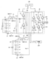
 本発明の実施例1である電池システムについて説明する。図1は、本実施例である電池システムの構成を示す図である。本実施例の電池システムは、車両に搭載される。この車両としては、電気自動車やハイブリッド自動車がある。電気自動車は、車両を走行させる動力源として、後述する組電池だけを備えている。ハイブリッド自動車は、車両を走行させる動力源として、後述する組電池の他に、エンジンや燃料電池を備えている。 A battery system that is Embodiment 1 of the present invention will be described. FIG. 1 is a diagram illustrating a configuration of a battery system according to the present embodiment. The battery system of the present embodiment is mounted on a vehicle. Such vehicles include electric vehicles and hybrid vehicles. The electric vehicle includes only an assembled battery described later as a power source for running the vehicle. The hybrid vehicle includes an engine and a fuel cell as a power source for running the vehicle in addition to the assembled battery described later.
 高容量型組電池10は、直列に接続された複数の単電池11を有する。高容量型組電池10に含まれる2つの単電池11には、ヒューズ12が接続されている。高出力型組電池20は、直列に接続された複数の単電池21を有する。高出力型組電池20に含まれる2つの単電池21には、ヒューズ22が接続されている。単電池11,21としては、ニッケル水素電池やリチウムイオン電池といった二次電池を用いることができる。 The high-capacity assembled battery 10 has a plurality of single cells 11 connected in series. A fuse 12 is connected to two unit cells 11 included in the high-capacity assembled battery 10. The high-power assembled battery 20 has a plurality of single cells 21 connected in series. A fuse 22 is connected to two unit cells 21 included in the high-power assembled battery 20. As the cells 11 and 21, secondary batteries such as nickel metal hydride batteries and lithium ion batteries can be used.
 高容量型組電池10は、高出力型組電池20よりも大きなエネルギ容量を有している。高出力型組電池20は、高容量型組電池10よりも大きな電流で充放電を行うことができる。図1では、組電池10,20を構成する複数の単電池11,21が直列に接続されているが、組電池10,20には、並列に接続された複数の単電池11,21が含まれていてもよい。組電池10,20の違いについては、後述する。 The high capacity assembled battery 10 has a larger energy capacity than the high output assembled battery 20. The high-power assembled battery 20 can be charged and discharged with a larger current than the high-capacity assembled battery 10. In FIG. 1, the plurality of single cells 11 and 21 constituting the assembled batteries 10 and 20 are connected in series, but the assembled batteries 10 and 20 include a plurality of single cells 11 and 21 connected in parallel. It may be. The difference between the assembled batteries 10 and 20 will be described later.
 電圧センサ13は、高容量型組電池10の端子間電圧を検出し、検出結果をコントローラ100に出力する。電流センサ14は、高容量型組電池10の充放電電流を検出し、検出結果をコントローラ100に出力する。電圧センサ23は、高出力型組電池20の端子間電圧を検出し、検出結果をコントローラ100に出力する。電流センサ24は、高出力型組電池20の充放電電流を検出し、検出結果をコントローラ100に出力する。 The voltage sensor 13 detects the voltage between the terminals of the high-capacity assembled battery 10 and outputs the detection result to the controller 100. The current sensor 14 detects the charge / discharge current of the high-capacity assembled battery 10 and outputs the detection result to the controller 100. The voltage sensor 23 detects the voltage between the terminals of the high-power assembled battery 20 and outputs the detection result to the controller 100. The current sensor 24 detects the charge / discharge current of the high-power assembled battery 20 and outputs the detection result to the controller 100.
 高容量型組電池10は、正極ラインPL1および負極ラインNL1を介して、昇圧コンバータ30に接続されている。コンデンサ16は、正極ラインPL1および負極ラインNL1に接続されており、正極ラインPL1および負極ラインNL1の間における電圧変動を平滑化する。 The high capacity assembled battery 10 is connected to the boost converter 30 via the positive electrode line PL1 and the negative electrode line NL1. Capacitor 16 is connected to positive electrode line PL1 and negative electrode line NL1, and smoothes voltage fluctuation between positive electrode line PL1 and negative electrode line NL1.
 正極ラインPL1には、システムメインリレーSMR-G1が設けられており、負極ラインNL1には、システムメインリレーSMR-B1が設けられている。システムメインリレーSMR-P1および制限抵抗15は、互いに直列に接続されているとともに、システムメインリレーSMR-G1に対して並列に接続されている。 The system main relay SMR-G1 is provided in the positive line PL1, and the system main relay SMR-B1 is provided in the negative line NL1. System main relay SMR-P1 and limiting resistor 15 are connected in series to each other and in parallel to system main relay SMR-G1.
 システムメインリレーSMR-G1,SMR-P1,SMR-B1は、コントローラ100からの制御信号を受けて、オンおよびオフの間で切り替わる。高容量型組電池10を昇圧コンバータ30と接続するとき、まず、システムメインリレーSMR-P1,SMR-B1がオフからオンに切り替わる。このとき、制限抵抗15に電流が流れる。次に、システムメインリレーSMR-G1がオフからオンに切り替わるとともに、システムメインリレーSMR-P1がオンからオフに切り替わる。 System main relays SMR-G1, SMR-P1, and SMR-B1 are switched between on and off in response to a control signal from controller 100. When the high-capacity assembled battery 10 is connected to the boost converter 30, first, the system main relays SMR-P1 and SMR-B1 are switched from OFF to ON. At this time, a current flows through the limiting resistor 15. Next, the system main relay SMR-G1 is switched from OFF to ON, and the system main relay SMR-P1 is switched from ON to OFF.
 これにより、高容量型組電池10および昇圧コンバータ30の接続が完了する。高容量型組電池10および昇圧コンバータ30の接続を遮断するときには、システムメインリレーSMR-G1,SMR-B1がオンからオフに切り替わる。 This completes the connection between the high-capacity assembled battery 10 and the boost converter 30. When the connection between the high-capacity assembled battery 10 and the boost converter 30 is cut off, the system main relays SMR-G1 and SMR-B1 are switched from on to off.
 高出力型組電池20は、正極ラインPL2および負極ラインNL2を介して、インバータ40と接続されている。正極ラインPL2には、システムメインリレーSMR-G2が設けられており、負極ラインNL2には、システムメインリレーSMR-B2が設けられている。システムメインリレーSMR-P2および制限抵抗25は、互いに直列に接続されているとともに、システムメインリレーSMR-G2に対して並列に接続されている。 The high-power assembled battery 20 is connected to the inverter 40 via the positive electrode line PL2 and the negative electrode line NL2. A system main relay SMR-G2 is provided in the positive electrode line PL2, and a system main relay SMR-B2 is provided in the negative electrode line NL2. System main relay SMR-P2 and limiting resistor 25 are connected in series to each other and in parallel to system main relay SMR-G2.
 システムメインリレーSMR-G2,SMR-P2,SMR-B2は、コントローラ100からの制御信号を受けて、オンおよびオフの間で切り替わる。高出力型組電池20をインバータ40と接続するとき、まず、システムメインリレーSMR-P2,SMR-B2がオフからオンに切り替わる。このとき、制限抵抗25に電流が流れる。次に、システムメインリレーSMR-G2がオフからオンに切り替わるとともに、システムメインリレーSMR-P2がオンからオフに切り替わる。 System main relays SMR-G2, SMR-P2, and SMR-B2 are switched between ON and OFF in response to a control signal from controller 100. When the high-power assembled battery 20 is connected to the inverter 40, first, the system main relays SMR-P2 and SMR-B2 are switched from OFF to ON. At this time, a current flows through the limiting resistor 25. Next, the system main relay SMR-G2 is switched from OFF to ON, and the system main relay SMR-P2 is switched from ON to OFF.
 これにより、高出力型組電池20およびインバータ40の接続が完了する。高出力型組電池20およびインバータ40の接続を遮断するときには、システムメインリレーSMR-G2,SMR-B2がオンからオフに切り替わる。 This completes the connection of the high-power assembled battery 20 and the inverter 40. When the connection between the high-power assembled battery 20 and the inverter 40 is cut off, the system main relays SMR-G2 and SMR-B2 are switched from on to off.
 昇圧コンバータ30は、正極ラインPL1および負極ラインNL1の間における電圧を昇圧してバスラインPB,NBの間に出力する。昇圧コンバータ30は、リアクトル31を有している。リアクトル31の一端は、正極ラインPL1と接続され、リアクトル31の他端は、トランジスタ32のエミッタと、トランジスタ33のコレクタとに接続されている。 Boost converter 30 boosts the voltage between positive line PL1 and negative line NL1, and outputs the boosted voltage between bus lines PB and NB. Boost converter 30 has a reactor 31. One end of reactor 31 is connected to positive electrode line PL <b> 1, and the other end of reactor 31 is connected to the emitter of transistor 32 and the collector of transistor 33.
 トランジスタ32,33は、バスラインPB,NBの間で、直列に接続されている。トランジスタ32,33としては、例えば、IGBT(Insulated Gate Bipolar Transistor)や、npn型トランジスタ、パワーMOSFET(Metal Oxide Semiconductor Field-Effect Transistor)を用いることができる。 The transistors 32 and 33 are connected in series between the bus lines PB and NB. As the transistors 32 and 33, for example, an IGBT (Insulated Gate Bipolar Transistor), an npn transistor, or a power MOSFET (Metal Oxide Semiconductor Field-Effect Transistor) can be used.
 ダイオード34,35は、トランジスタ32,33に対して、それぞれ並列に接続されている。具体的には、ダイオード34,35のアノードが、トランジスタ32,33のエミッタと接続され、ダイオード34,35のカソードが、トランジスタ32,33のコレクタと接続されている。コンデンサ17は、バスラインPB,NBに接続されており、バスラインPB,NBの間における電圧変動を平滑化する。 The diodes 34 and 35 are connected in parallel to the transistors 32 and 33, respectively. Specifically, the anodes of the diodes 34 and 35 are connected to the emitters of the transistors 32 and 33, and the cathodes of the diodes 34 and 35 are connected to the collectors of the transistors 32 and 33. The capacitor 17 is connected to the bus lines PB and NB, and smoothes voltage fluctuations between the bus lines PB and NB.
 昇圧コンバータ30は、昇圧動作や降圧動作を行う。昇圧コンバータ30が昇圧動作を行うとき、コントローラ100は、トランジスタ33をオンにするとともに、トランジスタ32をオフにする。これにより、高容量型組電池10からリアクトル31に電流が流れ、リアクトル31には、電流量に応じた磁場エネルギが蓄積される。次に、コントローラ100は、トランジスタ33をオンからオフに切り替えることにより、リアクトル31からダイオード34を介して、インバータ40に電流を流す。これにより、リアクトル31で蓄積されたエネルギが、昇圧コンバータ30から放出され、昇圧動作が行われる。 The step-up converter 30 performs a step-up operation and a step-down operation. When the boost converter 30 performs a boost operation, the controller 100 turns on the transistor 33 and turns off the transistor 32. Thereby, a current flows from the high-capacity assembled battery 10 to the reactor 31, and magnetic energy corresponding to the amount of current is accumulated in the reactor 31. Next, the controller 100 causes the current to flow from the reactor 31 to the inverter 40 via the diode 34 by switching the transistor 33 from on to off. As a result, the energy accumulated in reactor 31 is released from boost converter 30 and the boost operation is performed.
 昇圧コンバータ30が降圧動作を行うとき、コントローラ100は、トランジスタ32をオンにするとともに、トランジスタ33をオフにする。これにより、インバータ40からの電力が高容量型組電池10に供給され、高容量型組電池10の充電が行われる。 When the step-up converter 30 performs a step-down operation, the controller 100 turns on the transistor 32 and turns off the transistor 33. Thereby, the electric power from the inverter 40 is supplied to the high capacity type assembled battery 10, and the high capacity type assembled battery 10 is charged.
 インバータ40は、昇圧コンバータ30や高出力型組電池20から供給される直流電力を交流電力に変換して、モータジェネレータ(MG)50に出力する。また、インバータ40は、モータジェネレータ50が生成した交流電力を直流電力に変換して、昇圧コンバータ30に出力する。インバータ40は、コントローラ100からの制御信号を受けて動作する。モータジェネレータ50は、三相交流モータである。 The inverter 40 converts DC power supplied from the boost converter 30 and the high-power assembled battery 20 into AC power and outputs the AC power to the motor generator (MG) 50. Inverter 40 also converts AC power generated by motor generator 50 into DC power and outputs the DC power to boost converter 30. Inverter 40 operates in response to a control signal from controller 100. Motor generator 50 is a three-phase AC motor.
 インバータ40は、U相アームと、V相アームと、W相アームとを有する。U相アーム、V相アームおよびW相アームは、並列に接続されている。 The inverter 40 has a U-phase arm, a V-phase arm, and a W-phase arm. The U-phase arm, V-phase arm, and W-phase arm are connected in parallel.
 U相アームは、トランジスタ411,412およびダイオード413,414を有する。トランジスタ411,412は、バスラインPB,NBの間で、直列に接続されている。ダイオード413,414は、トランジスタ411,412に対して、それぞれ並列に接続されている。具体的には、ダイオード413,414のアノードは、トランジスタ411,412のエミッタと接続され、ダイオード413,414のカソードは、トランジスタ411,412のコレクタと接続されている。 The U-phase arm has transistors 411 and 412 and diodes 413 and 414. The transistors 411 and 412 are connected in series between the bus lines PB and NB. The diodes 413 and 414 are connected in parallel to the transistors 411 and 412, respectively. Specifically, the anodes of the diodes 413 and 414 are connected to the emitters of the transistors 411 and 412, and the cathodes of the diodes 413 and 414 are connected to the collectors of the transistors 411 and 412.
 V相アームは、トランジスタ421,422およびダイオード423,424を有する。トランジスタ421,422は、バスラインPB,NBの間で、直列に接続されている。ダイオード423,424は、トランジスタ421,422に対して、それぞれ並列に接続されている。具体的には、ダイオード423,424のアノードは、トランジスタ421,422のエミッタと接続され、ダイオード423,424のカソードは、トランジスタ421,422のコレクタと接続されている。 The V-phase arm has transistors 421 and 422 and diodes 423 and 424. The transistors 421 and 422 are connected in series between the bus lines PB and NB. The diodes 423 and 424 are connected in parallel to the transistors 421 and 422, respectively. Specifically, the anodes of the diodes 423 and 424 are connected to the emitters of the transistors 421 and 422, and the cathodes of the diodes 423 and 424 are connected to the collectors of the transistors 421 and 422.
 W相アームは、トランジスタ431,432およびダイオード433,434を有する。トランジスタ431,432は、バスラインPB,NBの間で、直列に接続されている。ダイオード433,434は、トランジスタ431,432に対して、それぞれ並列に接続されている。具体的には、ダイオード433,434のアノードは、トランジスタ431,432のエミッタと接続され、ダイオード433,434のカソードは、トランジスタ431,432のコレクタと接続されている。 The W-phase arm has transistors 431 and 432 and diodes 433 and 434. The transistors 431 and 432 are connected in series between the bus lines PB and NB. The diodes 433 and 434 are connected in parallel to the transistors 431 and 432, respectively. Specifically, the anodes of the diodes 433 and 434 are connected to the emitters of the transistors 431 and 432, and the cathodes of the diodes 433 and 434 are connected to the collectors of the transistors 431 and 432.
 モータジェネレータ50は、インバータ40から供給された電気エネルギを運動エネルギに変換する。モータジェネレータ50は、車輪と接続されており、モータジェネレータ50によって生成された運動エネルギ(回転力)は、車輪に伝達される。これにより、車両を走行させることができる。また、車両を減速させたり、停止させたりするとき、モータジェネレータ50は、車輪からの回転力を受けて発電する。モータジェネレータ50によって生成された交流電力は、インバータ40に出力される。 The motor generator 50 converts the electrical energy supplied from the inverter 40 into kinetic energy. Motor generator 50 is connected to wheels, and kinetic energy (rotational force) generated by motor generator 50 is transmitted to the wheels. Thereby, the vehicle can be driven. Further, when the vehicle is decelerated or stopped, the motor generator 50 receives the rotational force from the wheels and generates electric power. The AC power generated by the motor generator 50 is output to the inverter 40.
 充電器200は、バスラインPB,NBに接続されており、外部電源からの電力を組電池10,20に供給する。外部電源としては、例えば、商用電源を用いることができる。外部電源が交流電力を供給するときには、充電器200は、交流電力を直流電力に変換し、直流電力を組電池10,20に出力する。また、外部電源が直流電力を供給するときには、直流電力が組電池10,20に供給される。 The charger 200 is connected to the bus lines PB and NB and supplies power from the external power source to the assembled batteries 10 and 20. As the external power source, for example, a commercial power source can be used. When the external power supply supplies AC power, the charger 200 converts AC power into DC power and outputs the DC power to the assembled batteries 10 and 20. When the external power supply supplies DC power, DC power is supplied to the assembled batteries 10 and 20.
 次に、高容量型組電池10で用いられる単電池11の特性と、高出力型組電池20で用いられる単電池21の特性について説明する。表1は、単電池11,21の特性を比較したものである。表1に示す「高」および「低」は、2つの単電池11,21を比較したときの関係を示している。すなわち、「高」は、比較対象の単電池と比べて高いことを意味しており、「低」は、比較対象の単電池と比べて低いことを意味している。 Next, the characteristics of the unit cell 11 used in the high-capacity assembled battery 10 and the characteristics of the unit cell 21 used in the high-power assembled battery 20 will be described. Table 1 compares the characteristics of the cells 11 and 21. “High” and “Low” shown in Table 1 indicate the relationship when the two unit cells 11 and 21 are compared. That is, “high” means higher than the comparison target cell, and “low” means lower than the comparison unit cell.
Figure JPOXMLDOC01-appb-T000001
 単電池21の出力密度は、単電池11の出力密度よりも高い。単電池11,21の出力密度は、例えば、単電池の単位質量当たりの電力(単位[W/kg])や、単電池の単位体積当たりの電力(単位[W/L])として表すことができる。単電池11,21の質量又は体積を等しくしたとき、単電池21の出力[W]は、単電池11の出力[W]よりも高くなる。 The output density of the unit cell 21 is higher than the output density of the unit cell 11. The power density of the unit cells 11 and 21 can be expressed as, for example, power per unit mass of the unit cell (unit [W / kg]) or power per unit volume of the unit cell (unit [W / L]). it can. When the masses or the volumes of the unit cells 11 and 21 are made equal, the output [W] of the unit cell 21 is higher than the output [W] of the unit cell 11.
 また、単電池11,21の電極素子(正極素子又は負極素子)における出力密度は、例えば、電極素子の単位面積当たりの電流値(単位[mA/cm^2])として表すことができる。電極素子の出力密度に関して、単電池21は、単電池11よりも高い。ここで、電極素子の面積が等しいとき、単電池21の電極素子に流すことができる電流値は、単電池11の電極素子に流すことができる電流値よりも大きくなる。 Moreover, the output density in the electrode elements (positive electrode element or negative electrode element) of the unit cells 11 and 21 can be expressed, for example, as a current value (unit [mA / cm ^ 2]) per unit area of the electrode element. With respect to the output density of the electrode elements, the unit cell 21 is higher than the unit cell 11. Here, when the areas of the electrode elements are equal, the current value that can be passed through the electrode element of the unit cell 21 is larger than the current value that can be passed through the electrode element of the unit cell 11.
 単電池11の電力容量密度は、単電池21の電力容量密度よりも高い。単電池11,21の電力容量密度は、例えば、単電池の単位質量当たりの容量(単位[Wh/kg])や、単電池の単位体積当たりの容量(単位[Wh/L])として表すことができる。単電池11,21の質量又は体積を等しくしたとき、単電池11の電力容量[Wh]は、単電池21の電力容量[Wh]よりも大きくなる。 The power capacity density of the cell 11 is higher than the power capacity density of the cell 21. The power capacity density of the unit cells 11 and 21 is expressed as, for example, the capacity per unit mass (unit [Wh / kg]) of the unit cell or the capacity per unit volume of the unit cell (unit [Wh / L]). Can do. When the masses or volumes of the unit cells 11 and 21 are made equal, the power capacity [Wh] of the unit cell 11 is larger than the power capacity [Wh] of the unit cell 21.
 単電池11,21の電極素子における容量密度は、例えば、電極素子の単位質量当たりの容量(単位[mAh/g])や、電極素子の単位体積当たりの容量(単位[mAh/cc])として表すことができる。電極素子の容量密度に関して、単電池11は、単電池21よりも高い。ここで、電極素子の質量又は体積が等しいとき、単電池11の電極素子の容量は、単電池21の電極素子の容量よりも大きくなる。 The capacity density in the electrode elements of the unit cells 11 and 21 is, for example, the capacity per unit mass of the electrode elements (unit [mAh / g]) or the capacity per unit volume of the electrode elements (unit [mAh / cc]). Can be represented. The unit cell 11 is higher than the unit cell 21 with respect to the capacity density of the electrode elements. Here, when the mass or volume of the electrode element is equal, the capacity of the electrode element of the single battery 11 is larger than the capacity of the electrode element of the single battery 21.
 単電池11,21として、リチウムイオン二次電池を用いるとき、例えば、単電池11の負極活物質として、グラファイト(黒鉛)を用い、単電池11の正極活物質として、リチウム・ニッケル系複合酸化物を用いることができる。また、例えば、単電池21の負極活物質として、ハードカーボン(難黒鉛化炭素材料)を用い、単電池21の正極活物質として、リチウム・マンガン系複合酸化物を用いることができる。 When lithium ion secondary batteries are used as the single cells 11 and 21, for example, graphite (graphite) is used as the negative electrode active material of the single cell 11, and the lithium / nickel composite oxide is used as the positive electrode active material of the single cell 11. Can be used. Further, for example, hard carbon (non-graphitizable carbon material) can be used as the negative electrode active material of the single battery 21, and lithium / manganese composite oxide can be used as the positive electrode active material of the single battery 21.
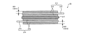
 図2は、単電池11における発電要素の構成を示す概略図であり、図3は、単電池21における発電要素の構成を示す概略図である。 FIG. 2 is a schematic diagram showing the configuration of the power generation element in the unit cell 11, and FIG. 3 is a schematic diagram showing the configuration of the power generation element in the unit cell 21.
 図2において、単電池11の発電要素を構成する正極素子111は、集電板112と、集電板112の両面に形成された活物質層113とを有する。単電池11がリチウムイオン二次電池であるとき、集電板112の材料としては、例えば、アルミニウムを用いることができる。活物質層113は、正極活物質、導電材およびバインダーなどを含んでいる。 In FIG. 2, the positive electrode element 111 constituting the power generation element of the unit cell 11 includes a current collector plate 112 and an active material layer 113 formed on both surfaces of the current collector plate 112. When the single battery 11 is a lithium ion secondary battery, as the material of the current collector plate 112, for example, aluminum can be used. The active material layer 113 includes a positive electrode active material, a conductive material, a binder, and the like.
 単電池11の発電要素を構成する負極素子114は、集電板115と、集電板115の両面に形成された活物質層116とを有する。単電池11がリチウムイオン二次電池であるとき、集電板115の材料としては、例えば、銅を用いることができる。活物質層116は、負極活物質、導電材およびバインダーなどを含んでいる。 The negative electrode element 114 constituting the power generation element of the unit cell 11 has a current collector plate 115 and an active material layer 116 formed on both surfaces of the current collector plate 115. When the unit cell 11 is a lithium ion secondary battery, for example, copper can be used as the material of the current collector plate 115. The active material layer 116 includes a negative electrode active material, a conductive material, a binder, and the like.
 正極素子111および負極素子114の間には、セパレータ117が配置されており、セパレータ117は、正極素子111の活物質層113と、負極素子114の活物質層116とに接触している。正極素子111、セパレータ117および負極素子114を、この順に積層して積層体を構成し、積層体を巻くことによって、発電要素を構成することができる。 A separator 117 is disposed between the positive electrode element 111 and the negative electrode element 114, and the separator 117 is in contact with the active material layer 113 of the positive electrode element 111 and the active material layer 116 of the negative electrode element 114. The power generation element can be configured by stacking the positive electrode element 111, the separator 117, and the negative electrode element 114 in this order to form a stacked body and winding the stacked body.
 本実施例では、集電板112の両面に活物質層113を形成したり、集電板115の両面に活物質層116を形成したりしているが、これに限るものではない。具体的には、いわゆるバイポーラ電極を用いることができる。バイポーラ電極では、集電板の一方の面に正極活物質層113が形成され、集電板の他方の面に負極活物質層116が形成されている。複数のバイポーラ電極の間にセパレータを挟んで積層することにより、発電要素を構成することができる。 In this embodiment, the active material layer 113 is formed on both surfaces of the current collector plate 112 and the active material layer 116 is formed on both surfaces of the current collector plate 115, but this is not restrictive. Specifically, so-called bipolar electrodes can be used. In the bipolar electrode, the positive electrode active material layer 113 is formed on one surface of the current collector plate, and the negative electrode active material layer 116 is formed on the other surface of the current collector plate. A power generation element can be configured by laminating a separator between a plurality of bipolar electrodes.
 図3において、単電池21の発電要素を構成する正極素子211は、集電板212と、集電板212の両面に形成された活物質層213とを有する。単電池21がリチウムイオン二次電池であるとき、集電板212の材料としては、例えば、アルミニウムを用いることができる。活物質層213は、正極活物質、導電材およびバインダーなどを含んでいる。 In FIG. 3, the positive electrode element 211 constituting the power generation element of the unit cell 21 has a current collector plate 212 and active material layers 213 formed on both surfaces of the current collector plate 212. When the unit cell 21 is a lithium ion secondary battery, as the material of the current collector plate 212, for example, aluminum can be used. The active material layer 213 includes a positive electrode active material, a conductive material, a binder, and the like.
 単電池21の発電要素を構成する負極素子214は、集電板215と、集電板215の両面に形成された活物質層216とを有する。単電池21がリチウムイオン二次電池であるとき、集電板215の材料としては、例えば、銅を用いることができる。活物質層216は、負極活物質、導電材およびバインダーなどを含んでいる。正極素子211および負極素子214の間には、セパレータ217が配置されており、セパレータ217は、正極素子211の活物質層213と、負極素子214の活物質層216とに接触している。 The negative electrode element 214 constituting the power generation element of the unit cell 21 has a current collector plate 215 and an active material layer 216 formed on both surfaces of the current collector plate 215. When the unit cell 21 is a lithium ion secondary battery, for example, copper can be used as the material of the current collector plate 215. The active material layer 216 includes a negative electrode active material, a conductive material, a binder, and the like. A separator 217 is disposed between the positive electrode element 211 and the negative electrode element 214, and the separator 217 is in contact with the active material layer 213 of the positive electrode element 211 and the active material layer 216 of the negative electrode element 214.
 図2および図3に示すように、単電池11および単電池21における正極素子111,211を比較したとき、活物質層213の厚さD21は、活物質層113の厚さD11よりも薄い。また、単電池11および単電池21における負極素子114,214を比較したとき、活物質層216の厚さD22は、活物質層116の厚さD12よりも薄い。活物質層213,216の厚さD21,D22が活物質層113,116の厚さD11,D12よりも薄いことにより、単電池21では、正極素子211および負極素子214の間で電流が流れやすくなる。したがって、単電池21の出力密度は、単電池11の出力密度よりも高くなる。 As shown in FIGS. 2 and 3, when the positive electrodes 111 and 211 in the unit cell 11 and the unit cell 21 are compared, the thickness D21 of the active material layer 213 is smaller than the thickness D11 of the active material layer 113. Further, when the negative electrode elements 114 and 214 in the unit cell 11 and the unit cell 21 are compared, the thickness D22 of the active material layer 216 is smaller than the thickness D12 of the active material layer 116. Since the thicknesses D21 and D22 of the active material layers 213 and 216 are thinner than the thicknesses D11 and D12 of the active material layers 113 and 116, current flows easily between the positive electrode element 211 and the negative electrode element 214 in the unit cell 21. Become. Therefore, the output density of the single cell 21 is higher than the output density of the single cell 11.
 ここで、活物質層における単位容量当たりの体積(単位[cc/mAh])に関して、活物質層213は、活物質層113よりも大きく、活物質層216は、活物質層116よりも大きい。活物質層113,116の厚さD11,D12は、活物質層213,216の厚さD21,D22よりも厚いため、単電池11の容量密度は、単電池21の容量密度よりも高くなる。また、単電池11の内部抵抗は、単電池21の内部抵抗よりも高くなる。 Here, regarding the volume per unit capacity (unit [cc / mAh]) in the active material layer, the active material layer 213 is larger than the active material layer 113, and the active material layer 216 is larger than the active material layer 116. Since the thicknesses D11 and D12 of the active material layers 113 and 116 are thicker than the thicknesses D21 and D22 of the active material layers 213 and 216, the capacity density of the unit cell 11 is higher than the capacity density of the unit cell 21. Further, the internal resistance of the unit cell 11 is higher than the internal resistance of the unit cell 21.
 次に、電池の入出力の温度依存性について説明する。表1に示すように、入出力の温度依存性に関して、単電池11は、単電池21よりも高い。すなわち、単電池11の入出力は、単電池21の入出力と比べて、温度変化に対して変化しやすい。図4は、温度に対する単電池11,21の出力特性を示している。図4において、横軸は温度を示し、縦軸は出力を示している。図4は、単電池11,21の出力特性を示しているが、単電池11,21の入力特性についても、図4と同様の関係がある。 Next, the temperature dependence of battery input / output will be described. As shown in Table 1, the unit cell 11 is higher than the unit cell 21 in terms of temperature dependency of input / output. That is, the input / output of the cell 11 is more likely to change with respect to the temperature change than the input / output of the cell 21. FIG. 4 shows the output characteristics of the cells 11 and 21 with respect to temperature. In FIG. 4, the horizontal axis indicates the temperature, and the vertical axis indicates the output. FIG. 4 shows the output characteristics of the cells 11 and 21, but the input characteristics of the cells 11 and 21 have the same relationship as in FIG.
 図4に示すように、温度が低下するにつれて、単電池11,21の出力性能が低下する。ここで、単電池11における出力性能の低下率は、単電池21における出力性能の低下率よりも高い。すなわち、単電池11の出力性能は、単電池21の出力性能に比べて、温度による影響を受けやすい。 As shown in FIG. 4, the output performance of the cells 11 and 21 decreases as the temperature decreases. Here, the rate of decrease in output performance of the unit cell 11 is higher than the rate of decrease in output performance of the unit cell 21. That is, the output performance of the cell 11 is more susceptible to temperature than the output performance of the cell 21.
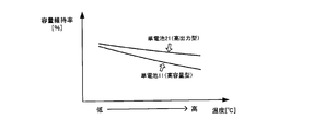
 図5は、単電池11,21の容量維持率と、温度との関係を示す図である。図5において、横軸は温度を示し、縦軸は容量維持率を示している。容量維持率とは、初期状態にある単電池11,21の容量(初期容量)と、使用状態(劣化状態)にある単電池11,21の容量(劣化容量)との比(劣化容量/初期容量)で表される。初期状態とは、単電池11,21を製造した直後の状態であり、単電池11,21を使用し始める前の状態をいう。図5に示すグラフは、各温度において、単電池の充放電を繰り返した後の単電池11,21の容量維持率を示している。 FIG. 5 is a diagram showing the relationship between the capacity maintenance rate of the cells 11 and 21 and the temperature. In FIG. 5, the horizontal axis indicates the temperature, and the vertical axis indicates the capacity retention rate. The capacity maintenance rate is a ratio of the capacity (initial capacity) of the single cells 11 and 21 in the initial state to the capacity (deteriorated capacity) of the single cells 11 and 21 in the use state (deteriorated state) (deteriorated capacity / initial Capacity). The initial state is a state immediately after the unit cells 11 and 21 are manufactured, and refers to a state before the unit cells 11 and 21 are used. The graph shown in FIG. 5 shows the capacity maintenance rate of the cells 11 and 21 after repeated charging and discharging of the cells at each temperature.
 図5に示すように、温度が上昇するにつれて、単電池11,21の容量維持率が低下する傾向がある。容量維持率の低下は、単電池11,21の劣化を表している。温度上昇に対する容量維持率の低下率に関して、単電池11は、単電池21よりも高い。言い換えれば、単電池11は、単電池21と比べて、温度上昇(温度変化)に対して劣化し易くなっている。このように、高容量型組電池10は、高出力型組電池20よりも温度に対する依存性が高くなっている。 As shown in FIG. 5, the capacity maintenance rate of the cells 11 and 21 tends to decrease as the temperature rises. The decrease in the capacity maintenance rate represents the deterioration of the cells 11 and 21. The unit cell 11 is higher than the unit cell 21 with respect to the rate of decrease of the capacity maintenance rate with respect to the temperature rise. In other words, the unit cell 11 is more susceptible to deterioration with respect to temperature rise (temperature change) than the unit cell 21. Thus, the high-capacity assembled battery 10 is more dependent on temperature than the high-power assembled battery 20.
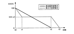
 本実施例の電池システムの動作について、図6に示すフローチャートを用いて説明する。図6に示す処理は、コントローラ100によって実行され、所定の周期で繰り返して行われる。図7は、組電池10,20におけるSOC(State of Charge)の変化(一例)を示す図である。図7において、横軸は時間を示し、縦軸はSOCを示す。SOCは、満充電容量に対して、現在の充電容量が占める割合である。 The operation of the battery system of the present embodiment will be described using the flowchart shown in FIG. The process shown in FIG. 6 is executed by the controller 100 and is repeatedly performed at a predetermined cycle. FIG. 7 is a diagram showing a change (an example) of SOC (State of Charge) in the assembled batteries 10 and 20. In FIG. 7, the horizontal axis indicates time, and the vertical axis indicates SOC. The SOC is a ratio of the current charging capacity to the full charging capacity.
 例えば、組電池10,20が満充電状態となっているとき、図6に示す処理を開始することができる。図7では、図6に示す処理を開始するタイミング(t0)において、組電池10,20のSOCが100%となっているが、これに限るものではない。組電池10,20のSOCが100%よりも低い値であっても、図2に示す処理を開始させることができる。ここで、組電池10,20のSOCを100%に近づけておけば、車両の走行距離を延ばすことができる。 For example, when the assembled batteries 10 and 20 are fully charged, the processing shown in FIG. 6 can be started. In FIG. 7, the SOC of the assembled batteries 10 and 20 is 100% at the timing (t0) when the processing shown in FIG. 6 is started, but the present invention is not limited to this. Even if the SOC of the assembled batteries 10 and 20 is a value lower than 100%, the processing shown in FIG. 2 can be started. Here, if the SOC of the assembled batteries 10 and 20 is close to 100%, the travel distance of the vehicle can be extended.
 図6に示す処理を開始するとき、システムメインリレーSMR-G1,SMR-B1,SMR-G2,SMR-B2がオンとなっており、組電池10,20は、負荷(昇圧コンバータ30やインバータ40)に接続されている。 When the processing shown in FIG. 6 is started, the system main relays SMR-G1, SMR-B1, SMR-G2, and SMR-B2 are turned on, and the assembled batteries 10 and 20 are connected to the load (the boost converter 30 and the inverter 40). )It is connected to the.
 ステップS101において、コントローラ100は、高容量型組電池10の放電を開始させる。これにより、高容量型組電池10のSOCは、低下し始める。 In step S101, the controller 100 starts discharging the high-capacity assembled battery 10. As a result, the SOC of the high-capacity assembled battery 10 begins to decrease.
 ステップS102において、コントローラ100は、車両の要求電力が、高容量型組電池10の出力電力よりも高いか否かを判別する。車両の要求電力は、例えば、アクセルペダル(図示せず)の操作に応じて変化する。運転者がアクセルペダルを踏み込むことにより、車両の要求電力が上昇すれば、車両の要求電力は、高容量型組電池10の出力電力よりも高くなりやすい。車両の要求電力が、高容量型組電池10の出力電力よりも高いときには、ステップS103に進み、そうでなければ、本処理を終了する。 In step S102, the controller 100 determines whether or not the required power of the vehicle is higher than the output power of the high-capacity assembled battery 10. The required electric power of the vehicle changes according to an operation of an accelerator pedal (not shown), for example. If the required power of the vehicle rises when the driver depresses the accelerator pedal, the required power of the vehicle tends to be higher than the output power of the high-capacity assembled battery 10. When the required power of the vehicle is higher than the output power of the high-capacity assembled battery 10, the process proceeds to step S103. Otherwise, the process is terminated.
 ステップS103において、コントローラ100は、高出力型組電池20を放電させる。これにより、組電池10,20の出力電力がモータジェネレータ50に供給され、車両の走行が行われる。高出力型組電池20は、高容量型組電池10よりも大きな電流で充放電を行うことができる。このため、車両の要求電力のうち、高容量型組電池20の出力電力を超えた分については、高出力型組電池20の出力電力を用いることにより、車両の要求電力を確保しやすくなる。 In step S103, the controller 100 discharges the high-power assembled battery 20. Thereby, the output power of the assembled batteries 10 and 20 is supplied to the motor generator 50, and the vehicle travels. The high-power assembled battery 20 can be charged and discharged with a larger current than the high-capacity assembled battery 10. For this reason, it is easy to secure the required power of the vehicle by using the output power of the high-power assembled battery 20 for the part of the required power of the vehicle that exceeds the output power of the high-capacity assembled battery 20.
 組電池10,20を放電させれば、図7に示すように、組電池10,20のSOCが低下し始める。モータジェネレータ50が生成した回生電力は、高出力型組電池20に蓄えることができる。 If the assembled batteries 10 and 20 are discharged, the SOC of the assembled batteries 10 and 20 starts to decrease as shown in FIG. The regenerative power generated by the motor generator 50 can be stored in the high-power assembled battery 20.
 ステップS104において、コントローラ100は、高出力型組電池20のSOCが基準値SOC_refよりも低いか否かを判別する。コントローラ100は、電圧センサ23の出力に基づいて、高出力型組電池20のSOCを推定することができる。 In step S104, the controller 100 determines whether or not the SOC of the high-power assembled battery 20 is lower than the reference value SOC_ref. The controller 100 can estimate the SOC of the high-power assembled battery 20 based on the output of the voltage sensor 23.
 高出力型組電池20のSOCは、高出力型組電池20のOCV(Open Circuit Voltage)と対応関係がある。SOCおよびOCVの対応関係を予め求めておけば、高出力型組電池20のOCVから、高出力型組電池20のSOCを特定することができる。高出力型組電池20のOCVは、高出力型組電池20のCCV(Closed Circuit Voltage)、言い換えれば、電圧センサ23による検出電圧と、高出力型組電池20の反応抵抗による電圧降下量とから求められる。 The SOC of the high-power assembled battery 20 has a corresponding relationship with the OCV (Open Circuit Voltage) of the high-power assembled battery 20. If the correspondence relationship between the SOC and the OCV is obtained in advance, the SOC of the high-power assembled battery 20 can be specified from the OCV of the high-power assembled battery 20. The OCV of the high-power assembled battery 20 is calculated from the CCV (Closed Circuit Voltage) of the high-power assembled battery 20, in other words, the voltage detected by the voltage sensor 23 and the voltage drop due to the reaction resistance of the high-power assembled battery 20. Desired.
 ここでは、電圧センサ23による検出電圧から、高出力型組電池20のSOCを推定しているが、これに限るものではない。例えば、高出力型組電池20の充放電電流を積算することにより、高出力型組電池20のSOCを推定することができる。高出力型組電池20の充放電電流は、電流センサ24を用いて取得することができる。 Here, the SOC of the high-power assembled battery 20 is estimated from the voltage detected by the voltage sensor 23, but the present invention is not limited to this. For example, the SOC of the high-power assembled battery 20 can be estimated by integrating the charge / discharge current of the high-power assembled battery 20. The charge / discharge current of the high-power assembled battery 20 can be obtained using the current sensor 24.
 基準値SOC_refは、100%よりも低く、0%よりも高い値であり、車両の走行性能などを考慮して、適宜設定することができる。例えば、基準値SOC_refは、以下に説明するように設定することができる。 The reference value SOC_ref is a value lower than 100% and higher than 0%, and can be set as appropriate in consideration of the running performance of the vehicle. For example, the reference value SOC_ref can be set as described below.
 図8は、高出力型組電池20の出力性能および入力性能を示している。図8において、縦軸は、高出力型組電池20の入力性能および出力性能を示し、横軸は、高出力型組電池20のSOCを示す。高出力型組電池20のSOCが上昇することに応じて、高出力型組電池20の出力性能は向上する。すなわち、高出力型組電池20のSOCが上昇することに応じて、高出力型組電池20の出力を確保しやすくなるとともに、高出力型組電池20の入力を確保し難くなる。言い換えれば、高出力型組電池20のSOCが低下することに応じて、高出力型組電池20の入力を確保しやすくなるとともに、高出力型組電池20の出力を確保し難くなる。 FIG. 8 shows the output performance and input performance of the high-power assembled battery 20. In FIG. 8, the vertical axis represents the input performance and output performance of the high-power assembled battery 20, and the horizontal axis represents the SOC of the high-power assembled battery 20. As the SOC of the high-power assembled battery 20 increases, the output performance of the high-power assembled battery 20 improves. That is, as the SOC of the high-power assembled battery 20 increases, it becomes easy to secure the output of the high-power assembled battery 20 and it becomes difficult to secure the input of the high-power assembled battery 20. In other words, as the SOC of the high-power assembled battery 20 decreases, it becomes easy to secure the input of the high-power assembled battery 20 and it is difficult to secure the output of the high-power assembled battery 20.
 基準値SOC_refは、出力性能を示す曲線と、入力性能を示す曲線とが互いに交わるときのSOCに設定することができる。このように基準値SOC_refを設定することにより、高出力型組電池20のSOCが基準値SOC_refであるときには、高出力型組電池20の出力および入力を確保し易くなる。すなわち、高出力型組電池20の入力又は出力だけが確保されるのを防止できる。 The reference value SOC_ref can be set to the SOC when the curve indicating the output performance and the curve indicating the input performance intersect each other. By setting the reference value SOC_ref in this way, it is easy to ensure the output and input of the high-power assembled battery 20 when the SOC of the high-power assembled battery 20 is the reference value SOC_ref. That is, it is possible to prevent only the input or output of the high-power assembled battery 20 from being secured.
 高出力型組電池20の入力を確保するだけでは、高出力型組電池20を放電(出力)することができず、要求電力を確保し難くなる。また、高出力型組電池20の出力を確保するだけでは、高出力型組電池20を充電(入力)することができず、回生電力を蓄えることができなくなってしまう。このように、高出力型組電池20の入力又は出力だけを確保すると、車両の走行性能を向上させにくくなる。 Only by securing the input of the high-power assembled battery 20, the high-power assembled battery 20 cannot be discharged (output), and it becomes difficult to secure the required power. In addition, simply securing the output of the high-power assembled battery 20 cannot charge (input) the high-power assembled battery 20 and cannot store regenerative power. Thus, if only the input or output of the high-power assembled battery 20 is secured, it becomes difficult to improve the running performance of the vehicle.
 基準値SOC_refは、図8で説明した値からずれていてもよい。基準値SOC_refが、図8で説明した値からずれていても、高出力型組電池20の入力および出力を確保することができる。図8で説明した値からのずれ(許容量)は、適宜設定することができる。 The reference value SOC_ref may deviate from the value described in FIG. Even if the reference value SOC_ref deviates from the value described with reference to FIG. 8, the input and output of the high-power assembled battery 20 can be ensured. The deviation (allowable amount) from the value described in FIG. 8 can be set as appropriate.
 ステップS104において、高出力型組電池20のSOCが基準値SOC_refよりも低いときには、ステップS105の処理に進み、そうでなければ、本処理を終了する。 In step S104, when the SOC of the high-power assembled battery 20 is lower than the reference value SOC_ref, the process proceeds to step S105. Otherwise, the process ends.
 ステップS105において、コントローラ100は、高出力型組電池20のSOCが基準値SOC_refに沿うように、高出力型組電池20の充放電を制御する。具体的には、高出力型組電池20のSOCが基準値SOC_refよりも低いとき、コントローラ100は、高出力型組電池20の充電を優先して、高出力型組電池20のSOCを基準値SOC_refに近づける。高出力型組電池20の充電を行うとき、モータジェネレータ50によって生成された回生電力を高出力型組電池20に供給したり、高容量型組電池10の出力電力を高出力型組電池20に供給したりすることができる。 In step S105, the controller 100 controls charging / discharging of the high-power assembled battery 20 so that the SOC of the high-power assembled battery 20 is along the reference value SOC_ref. Specifically, when the SOC of the high-power assembled battery 20 is lower than the reference value SOC_ref, the controller 100 gives priority to the charging of the high-power assembled battery 20 and sets the SOC of the high-power assembled battery 20 to the reference value. Move closer to SOC_ref. When charging the high-power assembled battery 20, the regenerative power generated by the motor generator 50 is supplied to the high-power assembled battery 20, or the output power of the high-capacity assembled battery 10 is supplied to the high-power assembled battery 20. Or can be supplied.
 一方、高出力型組電池20のSOCが基準値SOC_refよりも高いとき、コントローラ100は、高出力型組電池20の放電を優先して、高出力型組電池20のSOCを基準値SOC_refに近づける。高出力型組電池20の放電を行うときには、高出力型組電池20の出力電力をモータジェネレータ50に供給する。 On the other hand, when the SOC of the high-power assembled battery 20 is higher than the reference value SOC_ref, the controller 100 gives priority to discharging the high-power assembled battery 20 and brings the SOC of the high-power assembled battery 20 closer to the reference value SOC_ref. . When discharging the high-power assembled battery 20, the output power of the high-power assembled battery 20 is supplied to the motor generator 50.
 高出力型組電池20は、高容量型組電池10よりもエネルギ容量が小さいため、図7に示すように、高出力型組電池20のSOCは、高容量型組電池10のSOCよりも低下しやすいことがある。図7に示す例では、時刻t1において、高出力型組電池20のSOCが基準値SOC_refに到達している。時刻t1を経過した後において、コントローラ100は、高出力型組電池20のSOCが基準値SOC_refに沿うように、高出力型組電池20の充放電を制御する。 Since the high-power assembled battery 20 has a smaller energy capacity than the high-capacity assembled battery 10, the SOC of the high-power assembled battery 20 is lower than the SOC of the high-capacity assembled battery 10 as shown in FIG. It may be easy to do. In the example illustrated in FIG. 7, the SOC of the high-power assembled battery 20 reaches the reference value SOC_ref at time t1. After the elapse of time t1, the controller 100 controls charging / discharging of the high-power assembled battery 20 so that the SOC of the high-power assembled battery 20 follows the reference value SOC_ref.
 ステップS106において、コントローラ100は、高容量型組電池10のSOCが0%に到達したか否かを判別する。高出力型組電池20のSOCを推定する方法と同様の方法によって、高容量型組電池10のSOCを推定することができる。高容量型組電池10のSOCが0%に到達したときには、ステップS107の処理に進み、そうでなければ、本処理を終了する。 In step S106, the controller 100 determines whether or not the SOC of the high-capacity assembled battery 10 has reached 0%. The SOC of the high-capacity assembled battery 10 can be estimated by a method similar to the method of estimating the SOC of the high-power assembled battery 20. When the SOC of the high-capacity assembled battery 10 reaches 0%, the process proceeds to step S107. Otherwise, the process ends.
 ステップS107において、コントローラ100は、高容量型組電池10の充放電を停止する。図7では、時刻t2において、高容量型組電池10のSOCが0%に到達しており、時刻t2を経過した後においては、高容量型組電池10の充放電が停止される。ここで、モータジェネレータ50によって生成された回生電力は、高出力型組電池20に蓄えられる。本実施例では、高容量型組電池10のSOCが0%に到達するまで、高容量型組電池10を放電させているが、これに限るものではない。例えば、高容量型組電池10のSOCが0%に到達する直前に、高容量型組電池10の充放電を停止することができる。 In step S107, the controller 100 stops charging / discharging of the high-capacity assembled battery 10. In FIG. 7, the SOC of the high-capacity assembled battery 10 reaches 0% at time t2, and charging and discharging of the high-capacity assembled battery 10 is stopped after the time t2. Here, the regenerative electric power generated by the motor generator 50 is stored in the high-power assembled battery 20. In this embodiment, the high-capacity assembled battery 10 is discharged until the SOC of the high-capacity assembled battery 10 reaches 0%, but the present invention is not limited to this. For example, charging / discharging of the high-capacity assembled battery 10 can be stopped immediately before the SOC of the high-capacity assembled battery 10 reaches 0%.
 高容量型組電池10のSOCが100%から0%に変化するまで、高容量型組電池10を継続的に放電させて、高容量型組電池10に蓄えられた電気エネルギを使い切ることにより、車両の走行距離を延ばすことができる。また、高容量型組電池10の電力を用いることにより、高出力型組電池20からの電力供給を抑制することができる。すなわち、車両を走行させる上で、高出力型組電池20の電力を補足的に用いることができる。 By continuously discharging the high-capacity assembled battery 10 until the SOC of the high-capacity assembled battery 10 changes from 100% to 0%, the electric energy stored in the high-capacity assembled battery 10 is used up, The travel distance of the vehicle can be extended. Moreover, the power supply from the high-power assembled battery 20 can be suppressed by using the power of the high-capacity assembled battery 10. That is, the power of the high-power assembled battery 20 can be supplementarily used when the vehicle is running.
 ステップS108において、コントローラ100は、基準値SOC_refに基づく、高出力型組電池20の充放電制御を解除する。そして、コントローラ100は、高出力型組電池20を積極的に放電させる。高容量型組電池10のSOCが0%に到達しているため、車両の要求電力を確保するためには、高出力型組電池20を積極的に放電させる必要がある。これにより、図7に示すように、時刻t2が経過した後においては、高出力型組電池20のSOCが基準値SOC_refから低下し始める。 In step S108, the controller 100 cancels the charge / discharge control of the high-power assembled battery 20 based on the reference value SOC_ref. Then, the controller 100 positively discharges the high-power assembled battery 20. Since the SOC of the high-capacity assembled battery 10 has reached 0%, it is necessary to actively discharge the high-power assembled battery 20 in order to ensure the required power of the vehicle. Thereby, as shown in FIG. 7, after the time t2 has elapsed, the SOC of the high-power assembled battery 20 starts to decrease from the reference value SOC_ref.
 車両の走行パターンによっては、回生電力が高出力型組電池20に蓄えられるが、車両の走行に応じて、高出力型組電池20のSOCは低下しやすくなる。高出力型組電池20を放電し続ければ、時刻t3において、高出力型組電池20のSOCが0%に到達する。組電池10,20のSOCが0%に到達した後は、充電器200を用いることにより、組電池10,20を充電することができる。これにより、組電池10,20のSOCを100%に近づけることができる。組電池10,20を充電した後は、図6に示す処理を行うことができる。 Depending on the traveling pattern of the vehicle, regenerative power is stored in the high-power assembled battery 20, but the SOC of the high-power assembled battery 20 tends to decrease as the vehicle travels. If the high-power assembled battery 20 is continuously discharged, the SOC of the high-power assembled battery 20 reaches 0% at time t3. After the SOC of the assembled batteries 10 and 20 reaches 0%, the assembled batteries 10 and 20 can be charged by using the charger 200. Thereby, SOC of the assembled batteries 10 and 20 can be brought close to 100%. After the assembled batteries 10 and 20 are charged, the process shown in FIG. 6 can be performed.
 本実施例によれば、高容量型組電池10の出力電力を用いて車両を走行させることができる。また、車両の要求電力が、高容量型組電池10の出力電力を超えるときには、不足分の電力を、高出力型組電池20の出力電力で補うことができる。 According to this embodiment, the vehicle can be driven using the output power of the high-capacity assembled battery 10. Further, when the required power of the vehicle exceeds the output power of the high-capacity assembled battery 10, the insufficient power can be supplemented with the output power of the high-power assembled battery 20.
 図9は、車両の要求電力に応じて組電池10,20の使用状況を説明する図である。図9において、縦軸は電力を示し、横軸は時間を示す。図9に示す波形は、車両の要求電力(一例)を示している。車両の要求電力は、車両の走行パターンに応じて変化する。 FIG. 9 is a diagram for explaining the usage status of the assembled batteries 10 and 20 according to the required power of the vehicle. In FIG. 9, the vertical axis represents power, and the horizontal axis represents time. The waveform shown in FIG. 9 indicates the required power (one example) of the vehicle. The required power of the vehicle changes according to the traveling pattern of the vehicle.
 車両の要求電力が、高容量型組電池10の出力電力に到達していないときには、高容量型組電池10の出力だけを用いて、車両を走行させることができる。一方、車両の要求電力が、高容量型組電池10の出力電力を超えているときには、組電池10,20の出力を用いて車両を走行させることができる。 When the required power of the vehicle does not reach the output power of the high capacity assembled battery 10, the vehicle can be driven using only the output of the high capacity assembled battery 10. On the other hand, when the required power of the vehicle exceeds the output power of the high-capacity assembled battery 10, the vehicle can be run using the outputs of the assembled batteries 10 and 20.
 高容量型組電池10の電力としては、例えば、負荷の電力の平均値とすることができる。ここでいう負荷とは、インバータ40およびモータジェネレータ50である。負荷の電力は、時刻に応じて変化するため、平均値としては、所定時間内における負荷の電力の平均値とすることができる。所定時間は、適宜設定することができ、例えば、数秒に設定することができる。コントローラ100は、直近における負荷電力の平均値を算出し、算出された平均値を、高容量型組電池10からインバータ40に供給される電力として設定することができる。 The power of the high-capacity assembled battery 10 can be, for example, an average value of load power. The loads referred to here are the inverter 40 and the motor generator 50. Since the power of the load changes according to the time, the average value can be the average value of the power of the load within a predetermined time. The predetermined time can be set as appropriate, and can be set to several seconds, for example. The controller 100 can calculate the average value of the most recent load power, and can set the calculated average value as the power supplied from the high-capacity assembled battery 10 to the inverter 40.
 コントローラ100は、昇圧コンバータ30のリアクトル31に流れる電流値を制御することにより、高容量型組電池10からインバータ40に供給される電力を、負荷電力の平均値とすることができる。昇圧コンバータ30に対する制御指令値となる電流値は、負荷電力の平均値を、インバータ40の電圧(バスラインPB,NBの間の電圧)で割った値とすることができる。 The controller 100 can control the value of the current flowing through the reactor 31 of the boost converter 30 to set the power supplied from the high-capacity assembled battery 10 to the inverter 40 as the average value of the load power. The current value serving as the control command value for boost converter 30 can be a value obtained by dividing the average value of the load power by the voltage of inverter 40 (the voltage between bus lines PB and NB).
 高容量型組電池10の出力電力を、一定値(負荷電力の平均値)に維持することにより、定電流に近い状態で、高容量型組電池10を放電させることができる。これにより、高容量型組電池10において、過電流や過電圧の発生を抑制することができ、高容量型組電池10の定格電圧および定格電流を確保することができる。 The high-capacity assembled battery 10 can be discharged in a state close to a constant current by maintaining the output power of the high-capacity assembled battery 10 at a constant value (average value of load power). Thereby, in high capacity type assembled battery 10, generation | occurrence | production of an overcurrent and an overvoltage can be suppressed, and the rated voltage and rated current of high capacity type assembled battery 10 can be ensured.
 上述したように、高容量型組電池10は、高出力型組電池20よりも内部抵抗が高くなるため、発熱などを抑制するためには、高容量型組電池10において、定格電圧や定格電流を確保する必要がある。また、上述したように、高容量型組電池10は、高出力型組電池20よりも温度依存性が高く、温度が高いほど、劣化しやすい。このため、高容量型組電池10の発熱を抑制することにより、高容量型組電池10の劣化を抑制することができる。 As described above, the high-capacity assembled battery 10 has an internal resistance higher than that of the high-power assembled battery 20, and therefore, in order to suppress heat generation, the high-capacity assembled battery 10 has a rated voltage and a rated current. It is necessary to ensure. Further, as described above, the high-capacity assembled battery 10 has a higher temperature dependency than the high-power assembled battery 20, and is more likely to deteriorate as the temperature increases. For this reason, the deterioration of the high-capacity assembled battery 10 can be suppressed by suppressing the heat generation of the high-capacity assembled battery 10.
 本実施例では、昇圧コンバータ30を用いて、高容量型組電池10の出力電圧を昇圧しているが、これに限るものではない。すなわち、昇圧コンバータ30を省略することもできる。この場合には、高容量型組電池10からインバータ40に供給される電力を一定値に維持するための電力変換器を設ける必要がある。
 
 
In the present embodiment, the boost converter 30 is used to boost the output voltage of the high-capacity assembled battery 10, but this is not restrictive. That is, the boost converter 30 can be omitted. In this case, it is necessary to provide a power converter for maintaining the power supplied from the high-capacity assembled battery 10 to the inverter 40 at a constant value.

Claims (13)

  1.  車両を走行させる駆動源であるモータと、
     前記モータに電力を供給可能な高容量型組電池および高出力型組電池と、
     前記高容量型組電池および前記高出力型組電池の充放電を制御するコントローラと、を有し、
     前記高容量型組電池は、前記高出力型組電池より相対的に大きなエネルギ容量を有し、前記高出力型組電池は、前記高容量型組電池より相対的に大きな電流で充放電が可能であり、
     前記コントローラは、
     前記高容量型組電池を継続的に放電するとともに、前記高容量型組電池を継続的に放電している間、前記高出力型組電池のSOCが所定値に沿うように前記高出力型組電池の充放電を制御し、
     前記高容量型組電池を継続的に放電していないとき、前記高出力型組電池のSOCが前記所定値よりも低下する方向に、前記高出力型組電池を継続的に放電させる、
    ことを特徴とする電池システム。
    A motor as a drive source for running the vehicle;
    A high-capacity assembled battery and a high-power assembled battery capable of supplying electric power to the motor;
    A controller for controlling charging and discharging of the high-capacity assembled battery and the high-power assembled battery,
    The high-capacity assembled battery has a relatively larger energy capacity than the high-power assembled battery, and the high-power assembled battery can be charged / discharged with a relatively larger current than the high-capacity assembled battery. And
    The controller is
    While continuously discharging the high-capacity assembled battery and continuously discharging the high-capacity assembled battery, the high-power assembled battery is adjusted so that the SOC of the high-power assembled battery follows a predetermined value. Control the charge and discharge of the battery,
    When the high-capacity assembled battery is not continuously discharged, the high-power assembled battery is continuously discharged in a direction in which the SOC of the high-power assembled battery decreases below the predetermined value.
    A battery system characterized by that.
  2.  前記高容量型組電池の出力電力を、前記モータに供給される電力に変換する電力変換器を有しており、
     前記コントローラは、前記電力変換器の制御により、前記高容量型組電池から前記モータに供給される電力を一定電力に維持することを特徴とする請求項1に記載の電池システム。
    A power converter for converting the output power of the high-capacity assembled battery into power supplied to the motor;
    The battery system according to claim 1, wherein the controller maintains the power supplied from the high-capacity assembled battery to the motor at a constant power under the control of the power converter.
  3.  前記電力変換器は、前記高容量型組電池の出力電圧を昇圧する昇圧コンバータであり、
     前記コントローラは、前記昇圧コンバータのリアクトルに流れる電流値を制御して、前記昇圧コンバータから前記モータに出力される電力を一定電力に維持することを特徴とする請求項2に記載の電池システム。
    The power converter is a boost converter that boosts the output voltage of the high-capacity assembled battery,
    3. The battery system according to claim 2, wherein the controller controls a value of a current flowing through a reactor of the boost converter to maintain power output from the boost converter to the motor at a constant power.
  4.  前記高出力型組電池は、前記電力変換器および前記モータを接続する電力線と接続されていることを特徴とする請求項2又は3に記載の電池システム。 The battery system according to claim 2 or 3, wherein the high-power assembled battery is connected to a power line connecting the power converter and the motor.
  5.  前記一定電力は、所定時間内における要求電力の平均値であることを特徴とする請求項2から4のいずれか1つに記載の電池システム。 The battery system according to any one of claims 2 to 4, wherein the constant power is an average value of required power within a predetermined time.
  6.  前記コントローラは、要求電力のうち、前記高容量型組電池の出力電力を超える電力を、前記高出力型組電池から出力させることを特徴とする請求項1から5のいずれか1つに記載の電池システム。 The said controller makes the electric power exceeding the output power of the said high capacity | capacitance type assembled battery among required electric power be output from the said high output type assembled battery, The one of Claim 1 to 5 characterized by the above-mentioned. Battery system.
  7.  前記高容量型組電池および前記高出力型組電池を継続的に放電していないとき、前記高容量型組電池および前記高出力型組電池は、車両の外部に設けられた電源からの電力を受けて充電を行うことを特徴とする請求項1から6のいずれか1つに記載の電池システム。 When the high-capacity assembled battery and the high-power assembled battery are not continuously discharged, the high-capacity assembled battery and the high-power assembled battery receive power from a power source provided outside the vehicle. The battery system according to any one of claims 1 to 6, wherein the battery system is charged by receiving the battery.
  8.  車両を走行させる駆動源であるモータに電力を供給可能な高容量型組電池および高出力型組電池の充放電を制御する制御方法であって、
     前記高容量型組電池は、前記高出力型組電池より相対的に大きなエネルギ容量を有し、前記高出力型組電池は、前記高容量型組電池より相対的に大きな電流で充放電が可能であり、
     前記高容量型組電池を継続的に放電し、
     前記高容量型組電池を継続的に放電している間、前記高出力型組電池のSOCが所定値に沿うように前記高出力型組電池の充放電を制御し、
     前記高容量型組電池を継続的に放電していないとき、前記高出力型組電池のSOCが前記所定値よりも低下する方向に、前記高出力型組電池を継続的に放電させる、
    ことを特徴とする制御方法。
    A control method for controlling charging / discharging of a high-capacity assembled battery and a high-capacity assembled battery that can supply power to a motor that is a drive source for driving the vehicle,
    The high-capacity assembled battery has a relatively larger energy capacity than the high-power assembled battery, and the high-power assembled battery can be charged / discharged with a relatively larger current than the high-capacity assembled battery. And
    Discharging the high-capacity assembled battery continuously,
    While discharging the high-capacity assembled battery continuously, charge / discharge of the high-power assembled battery is controlled so that the SOC of the high-power assembled battery follows a predetermined value,
    When the high-capacity assembled battery is not continuously discharged, the high-power assembled battery is continuously discharged in a direction in which the SOC of the high-power assembled battery decreases below the predetermined value.
    A control method characterized by that.
  9.  前記高容量型組電池から前記モータに供給される電力を一定電力に維持することを特徴とする請求項8に記載の制御方法。 The control method according to claim 8, wherein the power supplied from the high-capacity assembled battery to the motor is maintained at a constant power.
  10.  昇圧コンバータを用いて、前記高容量型組電池の出力電圧を昇圧するとともに、昇圧された電圧を前記モータに出力し、
     前記昇圧コンバータに流れる電流を制御して、前記昇圧コンバータから前記モータに出力される電力を一定電力に維持することを特徴とする請求項9に記載の制御方法。
    Using a boost converter, boost the output voltage of the high-capacity assembled battery, and output the boosted voltage to the motor,
    10. The control method according to claim 9, wherein a current flowing through the boost converter is controlled to maintain the power output from the boost converter to the motor at a constant power.
  11.  前記一定電力は、所定時間内における要求電力の平均値であることを特徴とする請求項9又は10に記載の制御方法。 The control method according to claim 9 or 10, wherein the constant power is an average value of required power within a predetermined time.
  12.  前記高出力型組電池は、要求電力のうち、前記高容量型組電池の出力電力を超える電力を出力することを特徴とする請求項8から11のいずれか1つに記載の制御方法。 The control method according to any one of claims 8 to 11, wherein the high-power assembled battery outputs a power exceeding the output power of the high-capacity assembled battery among the required power.
  13.  前記高容量型組電池および前記高出力型組電池を継続的に放電していないとき、車両の外部に設けられた電源からの電力供給により、前記高容量型組電池および前記高出力型組電池を充電することを特徴とする請求項8から12のいずれか1つに記載の制御方法。 When the high-capacity assembled battery and the high-power assembled battery are not continuously discharged, the high-capacity assembled battery and the high-power assembled battery are supplied by power supply from a power source provided outside the vehicle. The control method according to any one of claims 8 to 12, characterized in that the battery is charged.
PCT/JP2011/005144 2011-09-13 2011-09-13 Vehicle battery system and method for controlling same WO2013038441A1 (en)

Priority Applications (5)

Application Number Priority Date Filing Date Title
PCT/JP2011/005144 WO2013038441A1 (en) 2011-09-13 2011-09-13 Vehicle battery system and method for controlling same
JP2012519835A JP5321742B1 (en) 2011-09-13 2011-09-13 Vehicle battery system and control method thereof
EP11835317.6A EP2665151B1 (en) 2011-09-13 2011-09-13 Vehicle battery system and method for controlling same
CN201180009809.5A CN103222148B (en) 2011-09-13 2011-09-13 Vehicle battery system and method for controlling same
US13/505,648 US8884461B2 (en) 2011-09-13 2011-09-13 Battery system for vehicle and control method thereof

Applications Claiming Priority (1)

Application Number Priority Date Filing Date Title
PCT/JP2011/005144 WO2013038441A1 (en) 2011-09-13 2011-09-13 Vehicle battery system and method for controlling same

Publications (1)

Publication Number Publication Date
WO2013038441A1 true WO2013038441A1 (en) 2013-03-21

Family

ID=47882718

Family Applications (1)

Application Number Title Priority Date Filing Date
PCT/JP2011/005144 WO2013038441A1 (en) 2011-09-13 2011-09-13 Vehicle battery system and method for controlling same

Country Status (5)

Country Link
US (1) US8884461B2 (en)
EP (1) EP2665151B1 (en)
JP (1) JP5321742B1 (en)
CN (1) CN103222148B (en)
WO (1) WO2013038441A1 (en)

Cited By (9)

* Cited by examiner, † Cited by third party
Publication number Priority date Publication date Assignee Title
JP2015084638A (en) * 2013-10-11 2015-04-30 ゼネラル・エレクトリック・カンパニイ Propulsion system and method for driving vehicle
CN105874681A (en) * 2014-03-31 2016-08-17 三洋电机株式会社 Power supply system
JP2017099241A (en) * 2015-11-28 2017-06-01 本田技研工業株式会社 Power supply system, transportation equipment and power transmission method
EP2982019B1 (en) * 2013-04-02 2017-08-02 Faiveley Transport Tours Device forming an interface between an auxiliary power supply system and a power generation module in a rail vehicle
JP2017163652A (en) * 2016-03-08 2017-09-14 本田技研工業株式会社 Power supply system
US10040368B2 (en) 2015-11-28 2018-08-07 Honda Motor Co., Ltd. Power supply system, transportation device, and power transmission method including changing a proportion of a charging prower
JP2020530255A (en) * 2017-08-10 2020-10-15 ズークス インコーポレイテッド Smart battery circuit
WO2023145232A1 (en) * 2022-01-25 2023-08-03 トヨタ自動車株式会社 Vehicle
JP7449750B2 (en) 2020-03-30 2024-03-14 本田技研工業株式会社 Power systems and electric vehicles

Families Citing this family (18)

* Cited by examiner, † Cited by third party
Publication number Priority date Publication date Assignee Title
WO2014118903A1 (en) * 2013-01-30 2014-08-07 株式会社 日立製作所 Combined battery system
TWI532294B (en) * 2014-01-09 2016-05-01 Portable compound battery system
FR3019395B1 (en) * 2014-03-28 2017-09-29 Peugeot Citroen Automobiles Sa SYSTEM FOR SUPPLYING AN ELECTRICAL TRACTION MACHINE OF A HYBRID VEHICLE, FOR RECHARGING ITS BATTERY WITH AN EXTERNAL NETWORK
US10218264B1 (en) * 2014-04-02 2019-02-26 Raytheon Company Method of eliminating power converter input power variations and minimizing energy storage capacitor requirements for a pulsed load system
AU2014268249B1 (en) * 2014-11-28 2015-07-09 Power Management Technologies Pty Ltd Power management for an electric drive system
US20170072812A1 (en) * 2015-09-16 2017-03-16 Qualcomm Incorporated Battery Management Systems for Autonomous Vehicles
JP6284921B2 (en) * 2015-11-28 2018-02-28 本田技研工業株式会社 Power supply system, transport equipment, and power transmission method
JP6223406B2 (en) * 2015-11-28 2017-11-01 本田技研工業株式会社 Power supply system
WO2017150195A1 (en) * 2016-03-01 2017-09-08 ソニー株式会社 Battery pack and charge-discharge control method
DE102016207574A1 (en) 2016-05-03 2017-11-09 Robert Bosch Gmbh Method for operating a battery system, battery management system and battery system
DE102016207578A1 (en) 2016-05-03 2017-11-09 Robert Bosch Gmbh Method for operating a battery system, battery management system and battery system
DE102016212554A1 (en) * 2016-07-11 2018-01-11 Robert Bosch Gmbh A method of adjusting the voltage provided by a high performance electrochemical store and a system for operating a load
DE102016220089A1 (en) 2016-10-14 2018-04-19 Robert Bosch Gmbh Method, machine-readable storage medium and electronic control unit for operating an electrical energy storage system and corresponding electrical energy storage system
DE102017211001A1 (en) 2017-06-29 2019-01-03 Robert Bosch Gmbh Hybrid battery system and method of operating a hybrid battery system
CN111886770A (en) * 2018-03-20 2020-11-03 株式会社日立制作所 Composite electricity storage system
JP7163714B2 (en) * 2018-10-18 2022-11-01 トヨタ自動車株式会社 vehicle power supply
JP7363463B2 (en) * 2019-12-23 2023-10-18 トヨタ自動車株式会社 fuel cell vehicle
JP7450523B2 (en) * 2020-12-08 2024-03-15 プライムプラネットエナジー&ソリューションズ株式会社 Vehicle driving system and vehicle

Citations (6)

* Cited by examiner, † Cited by third party
Publication number Priority date Publication date Assignee Title
JPH09298806A (en) 1996-05-01 1997-11-18 Yamaha Motor Co Ltd Power supply method for electric motor car and its equipment
JPH10271611A (en) * 1997-03-25 1998-10-09 Nissan Diesel Motor Co Ltd Power supply system for electric vehicle
JP2000295784A (en) * 1999-04-08 2000-10-20 Sekisui Chem Co Ltd Power storage system
JP2004111242A (en) 2002-09-19 2004-04-08 Nissan Motor Co Ltd Battery pack
JP2004215456A (en) * 2003-01-08 2004-07-29 Ngk Insulators Ltd Hybrid battery system
JP2006121874A (en) * 2004-10-25 2006-05-11 Nissan Motor Co Ltd Power supply apparatus and vehicle equipped with same

Family Cites Families (3)

* Cited by examiner, † Cited by third party
Publication number Priority date Publication date Assignee Title
US6437544B1 (en) * 2001-12-20 2002-08-20 Tai-Her Yang Serial stage power supply combination for emergency auxiliary charging apparatus
JP4285458B2 (en) * 2005-08-08 2009-06-24 トヨタ自動車株式会社 Vehicle power supply apparatus and control method thereof
JP5250928B2 (en) * 2005-10-24 2013-07-31 日産自動車株式会社 Battery system charge state recovery method

Patent Citations (6)

* Cited by examiner, † Cited by third party
Publication number Priority date Publication date Assignee Title
JPH09298806A (en) 1996-05-01 1997-11-18 Yamaha Motor Co Ltd Power supply method for electric motor car and its equipment
JPH10271611A (en) * 1997-03-25 1998-10-09 Nissan Diesel Motor Co Ltd Power supply system for electric vehicle
JP2000295784A (en) * 1999-04-08 2000-10-20 Sekisui Chem Co Ltd Power storage system
JP2004111242A (en) 2002-09-19 2004-04-08 Nissan Motor Co Ltd Battery pack
JP2004215456A (en) * 2003-01-08 2004-07-29 Ngk Insulators Ltd Hybrid battery system
JP2006121874A (en) * 2004-10-25 2006-05-11 Nissan Motor Co Ltd Power supply apparatus and vehicle equipped with same

Non-Patent Citations (1)

* Cited by examiner, † Cited by third party
Title
See also references of EP2665151A4

Cited By (13)

* Cited by examiner, † Cited by third party
Publication number Priority date Publication date Assignee Title
EP2982019B1 (en) * 2013-04-02 2017-08-02 Faiveley Transport Tours Device forming an interface between an auxiliary power supply system and a power generation module in a rail vehicle
US10608465B2 (en) 2013-04-02 2020-03-31 Faiveley Transport Tours Device forming an interface between an auxiliary power supply system and a power generation module in a rail vehicle
JP2015084638A (en) * 2013-10-11 2015-04-30 ゼネラル・エレクトリック・カンパニイ Propulsion system and method for driving vehicle
CN105874681B (en) * 2014-03-31 2018-11-27 三洋电机株式会社 Power-supply system
CN105874681A (en) * 2014-03-31 2016-08-17 三洋电机株式会社 Power supply system
US10040368B2 (en) 2015-11-28 2018-08-07 Honda Motor Co., Ltd. Power supply system, transportation device, and power transmission method including changing a proportion of a charging prower
JP2017099241A (en) * 2015-11-28 2017-06-01 本田技研工業株式会社 Power supply system, transportation equipment and power transmission method
US10507735B2 (en) 2015-11-28 2019-12-17 Honda Motor Co., Ltd. Power supply system, transportation device, and power transmission method
JP2017163652A (en) * 2016-03-08 2017-09-14 本田技研工業株式会社 Power supply system
JP2020530255A (en) * 2017-08-10 2020-10-15 ズークス インコーポレイテッド Smart battery circuit
JP7191086B2 (en) 2017-08-10 2022-12-16 ズークス インコーポレイテッド smart battery circuit
JP7449750B2 (en) 2020-03-30 2024-03-14 本田技研工業株式会社 Power systems and electric vehicles
WO2023145232A1 (en) * 2022-01-25 2023-08-03 トヨタ自動車株式会社 Vehicle

Also Published As

Publication number Publication date
US8884461B2 (en) 2014-11-11
EP2665151A1 (en) 2013-11-20
JP5321742B1 (en) 2013-10-23
EP2665151A4 (en) 2015-08-26
JPWO2013038441A1 (en) 2015-03-23
CN103222148B (en) 2014-06-18
CN103222148A (en) 2013-07-24
EP2665151B1 (en) 2016-11-09
US20140203633A1 (en) 2014-07-24

Similar Documents

Publication Publication Date Title
JP5321742B1 (en) Vehicle battery system and control method thereof
JP5664446B2 (en) Battery system
JP6266670B2 (en) Power supply system, transport equipment, and power transmission method
JP4893804B2 (en) Vehicle power supply
JP3977841B2 (en) Battery power circuit
JP5660102B2 (en) Vehicle power supply
US10252623B2 (en) Charge/discharge system
JP2012234700A (en) Battery system
US9834100B2 (en) Charge/discharge system
JP6343599B2 (en) Drive device
US20150283913A1 (en) Electricity supply system having double power-storage devices of a hybrid or electric motor vehicle
JP2017041973A (en) Drive apparatus and transport machine
US10576835B2 (en) Energy storage device, transport apparatus, and control method
JP7069075B2 (en) Power system
US9738175B2 (en) Drive device, transport apparatus, and energy storage control method
JP2017070077A (en) Power storage device, transportation equipment, and control method
JP7096203B2 (en) Power system
JP5838840B2 (en) Battery system
JP6335860B2 (en) DRIVE DEVICE, ITS CONTROL METHOD, AND TRANSPORTATION DEVICE
JP2017041974A (en) Drive apparatus and control method therefor, and transport machine
JP2016032324A (en) Control system for rotating electrical machine mounted in vehicle

Legal Events

Date Code Title Description
ENP Entry into the national phase

Ref document number: 2012519835

Country of ref document: JP

Kind code of ref document: A

REEP Request for entry into the european phase

Ref document number: 2011835317

Country of ref document: EP

WWE Wipo information: entry into national phase

Ref document number: 13505648

Country of ref document: US

Ref document number: 2011835317

Country of ref document: EP

121 Ep: the epo has been informed by wipo that ep was designated in this application

Ref document number: 11835317

Country of ref document: EP

Kind code of ref document: A1

NENP Non-entry into the national phase

Ref country code: DE