WO2013027380A1 - Head mount display and display control method - Google Patents
Head mount display and display control method Download PDFInfo
- Publication number
- WO2013027380A1 WO2013027380A1 PCT/JP2012/005194 JP2012005194W WO2013027380A1 WO 2013027380 A1 WO2013027380 A1 WO 2013027380A1 JP 2012005194 W JP2012005194 W JP 2012005194W WO 2013027380 A1 WO2013027380 A1 WO 2013027380A1
- Authority
- WO
- WIPO (PCT)
- Prior art keywords
- display
- eye video
- video signal
- eye
- screen
- Prior art date
Links
- 238000000034 method Methods 0.000 title claims description 52
- 230000004044 response Effects 0.000 claims description 9
- 210000003128 head Anatomy 0.000 description 33
- 238000010586 diagram Methods 0.000 description 12
- 210000004556 brain Anatomy 0.000 description 6
- 230000003287 optical effect Effects 0.000 description 5
- 239000004973 liquid crystal related substance Substances 0.000 description 3
- 230000008569 process Effects 0.000 description 3
- 238000009877 rendering Methods 0.000 description 2
- 230000002194 synthesizing effect Effects 0.000 description 2
- 230000000007 visual effect Effects 0.000 description 2
- 206010047571 Visual impairment Diseases 0.000 description 1
- 230000015556 catabolic process Effects 0.000 description 1
- 238000006731 degradation reaction Methods 0.000 description 1
- 238000005401 electroluminescence Methods 0.000 description 1
- 230000006870 function Effects 0.000 description 1
- 230000004048 modification Effects 0.000 description 1
- 238000012986 modification Methods 0.000 description 1
- 210000001525 retina Anatomy 0.000 description 1
- 230000035807 sensation Effects 0.000 description 1
- 230000011664 signaling Effects 0.000 description 1
- 238000006467 substitution reaction Methods 0.000 description 1
- 230000007704 transition Effects 0.000 description 1
Images


Classifications
-
- H—ELECTRICITY
- H04—ELECTRIC COMMUNICATION TECHNIQUE
- H04N—PICTORIAL COMMUNICATION, e.g. TELEVISION
- H04N13/00—Stereoscopic video systems; Multi-view video systems; Details thereof
- H04N13/30—Image reproducers
- H04N13/332—Displays for viewing with the aid of special glasses or head-mounted displays [HMD]
- H04N13/344—Displays for viewing with the aid of special glasses or head-mounted displays [HMD] with head-mounted left-right displays
-
- G—PHYSICS
- G02—OPTICS
- G02B—OPTICAL ELEMENTS, SYSTEMS OR APPARATUS
- G02B27/00—Optical systems or apparatus not provided for by any of the groups G02B1/00 - G02B26/00, G02B30/00
- G02B27/01—Head-up displays
- G02B27/017—Head mounted
-
- G—PHYSICS
- G09—EDUCATION; CRYPTOGRAPHY; DISPLAY; ADVERTISING; SEALS
- G09G—ARRANGEMENTS OR CIRCUITS FOR CONTROL OF INDICATING DEVICES USING STATIC MEANS TO PRESENT VARIABLE INFORMATION
- G09G3/00—Control arrangements or circuits, of interest only in connection with visual indicators other than cathode-ray tubes
- G09G3/001—Control arrangements or circuits, of interest only in connection with visual indicators other than cathode-ray tubes using specific devices not provided for in groups G09G3/02 - G09G3/36, e.g. using an intermediate record carrier such as a film slide; Projection systems; Display of non-alphanumerical information, solely or in combination with alphanumerical information, e.g. digital display on projected diapositive as background
- G09G3/003—Control arrangements or circuits, of interest only in connection with visual indicators other than cathode-ray tubes using specific devices not provided for in groups G09G3/02 - G09G3/36, e.g. using an intermediate record carrier such as a film slide; Projection systems; Display of non-alphanumerical information, solely or in combination with alphanumerical information, e.g. digital display on projected diapositive as background to produce spatial visual effects
-
- G—PHYSICS
- G09—EDUCATION; CRYPTOGRAPHY; DISPLAY; ADVERTISING; SEALS
- G09G—ARRANGEMENTS OR CIRCUITS FOR CONTROL OF INDICATING DEVICES USING STATIC MEANS TO PRESENT VARIABLE INFORMATION
- G09G5/00—Control arrangements or circuits for visual indicators common to cathode-ray tube indicators and other visual indicators
- G09G5/14—Display of multiple viewports
-
- H—ELECTRICITY
- H04—ELECTRIC COMMUNICATION TECHNIQUE
- H04N—PICTORIAL COMMUNICATION, e.g. TELEVISION
- H04N13/00—Stereoscopic video systems; Multi-view video systems; Details thereof
- H04N13/30—Image reproducers
- H04N13/332—Displays for viewing with the aid of special glasses or head-mounted displays [HMD]
- H04N13/341—Displays for viewing with the aid of special glasses or head-mounted displays [HMD] using temporal multiplexing
-
- G—PHYSICS
- G02—OPTICS
- G02B—OPTICAL ELEMENTS, SYSTEMS OR APPARATUS
- G02B27/00—Optical systems or apparatus not provided for by any of the groups G02B1/00 - G02B26/00, G02B30/00
- G02B27/01—Head-up displays
- G02B27/0101—Head-up displays characterised by optical features
- G02B2027/0118—Head-up displays characterised by optical features comprising devices for improving the contrast of the display / brillance control visibility
-
- G—PHYSICS
- G02—OPTICS
- G02B—OPTICAL ELEMENTS, SYSTEMS OR APPARATUS
- G02B27/00—Optical systems or apparatus not provided for by any of the groups G02B1/00 - G02B26/00, G02B30/00
- G02B27/01—Head-up displays
- G02B27/0101—Head-up displays characterised by optical features
- G02B2027/014—Head-up displays characterised by optical features comprising information/image processing systems
-
- G—PHYSICS
- G02—OPTICS
- G02B—OPTICAL ELEMENTS, SYSTEMS OR APPARATUS
- G02B27/00—Optical systems or apparatus not provided for by any of the groups G02B1/00 - G02B26/00, G02B30/00
- G02B27/01—Head-up displays
- G02B27/017—Head mounted
- G02B2027/0178—Eyeglass type
-
- G—PHYSICS
- G09—EDUCATION; CRYPTOGRAPHY; DISPLAY; ADVERTISING; SEALS
- G09G—ARRANGEMENTS OR CIRCUITS FOR CONTROL OF INDICATING DEVICES USING STATIC MEANS TO PRESENT VARIABLE INFORMATION
- G09G2320/00—Control of display operating conditions
- G09G2320/04—Maintaining the quality of display appearance
- G09G2320/043—Preventing or counteracting the effects of ageing
- G09G2320/046—Dealing with screen burn-in prevention or compensation of the effects thereof
Definitions
- the technology disclosed in this description relates to a head mount display which is mounted on a user's head and used to view a video, and a display control method, and more particularly, to a head mount display and a display control method capable of preventing a burn-in phenomenon when a still image such as an OSD screen is displayed on a display panel.
- a display device that is mounted on the head and used to view a video, that is, ahead mount display(HMD) has been widely known.
- the head mount display includes left-eye and right-eye optical units, and is configured to control a visual sense and an auditory sense in conjunction with a headphone.
- the head mount display configured to completely block the outside world when mounted on the head implements increased virtual reality while viewing a video. Further, the head mount display can project different videos to the left and right eyes, and can provide a 3D image by displaying an image with parallax between the left and right eyes.
- a high-resolution display panel including a liquid crystal element or an organic electro-luminescence(EL) element may be used as left-eye and right-eye display units of a head mount display.
- EL organic electro-luminescence
- a display panel configured with a liquid crystal element, an organic EL element, or the like has been known to be likely to undergo the burn-in phenomenon in an area having a large brightness difference.
- a still image such as an onscreen display (OSD) screen is rendered to be superimposed on a video screen, an area having a large brightness difference occurs, and thus the burn-in phenomenon occurs in the area.
- OSD onscreen display
- the head mount display has a limitation to the number of operation buttons mountable to a main body thereof, and thus a user operation using an OSD screen is inevitably required.
- a user operation using an OSD screen is inevitably required.
- an OSD screen used to display a menu includes a menu background area and a menu phrase rendered on the background area.
- An OSD screen is basically a still image and is likely to have a large brightness difference. For this reason, when an OSD screen is displayed for a long time, the burn-in phenomenon occurs.
- a video screen is configured with various video sources such as a moving image, and thus a brightness difference between pixels changes. For this reason, the burn-in phenomenon is reduced to some extent.
- the burn-in phenomenon is reduced to some extent.
- the burn-in phenomenon remarkably occurs. Since a menu is often displayed such that the same phrase is repeatedly displayed, the burn-in is easily observed particularly in a boundary portion between the menu background area and a menu phrase.
- a liquid crystal display device has been proposed that prevents an afterimage phenomenon, in a state in which display content of the entire screen can be constantly determined, by sequentially moving pixels equally dispersed among pixels configuring a display screen and causing the moved pixels to display black (for example, see Patent Document 1).
- an organic light-emitting display device that suppresses the burn-in from being observed even when the same image is displayed for a longtime by moving a display position of the entire panel by a predetermined distance at predetermined time intervals (for example, see Patent Document 2).
- a technology according to claim 1 provides a display method comprising: displaying an on-screen display image defined by a left-eye video signal and a right-eye video signal, wherein the on-screen display image comprises text and background, and wherein the text is deleted alternately from one of the left-eye video signal and the right-eye video signal.
- alternately deleting is performed at predetermined time intervals during a time period in which the on-screen display image is displayed.
- each of the left-eye video signal and the right-eye video signal comprises a still image in addition to the on-screen display image.
- each of the left-eye video signal and the right-eye video signal comprises a moving image in addition to the on-screen display image.
- a display method comprising: displaying an on-screen display image defined by a left-eye video signal and a right-eye video signal, wherein the on-screen display image comprises text and background, and wherein the text is thinned relative to the background by alternately reducing a display signal level of the text for one of the left-eye video signal and the right-eye video signal, wherein the display signal level is reduced from a high display signal level, which is below a full display signal level, to a low display signal level.
- an image display system comprising: at least one control unit for generating an on-screen display image defined by a left-eye video signal and a right-eye video signal, wherein the on-screen display image comprises text and background, and wherein the text is deleted alternately from one of the left-eye video signal and the right-eye video signal; a left-eye display panel for displaying the left-eye video signal; and a right-eye display panel for displaying the right-eye video signal.
- a head mount display and a display control method which are excellent and capable of appropriately preventing the burn-in phenomenon, particularly in a boundary portion between a menu background area and a menu phrase when a video, in which an OSD screen including the menu background area and the menu phrase is superimposed on a video screen, is displayed on a display panel.
- Fig. 1 is a diagram schematically illustrating a configuration of an image display system including a head mount display.
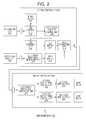
- Fig. 2 is a diagram schematically illustrating an internal configuration of a head mount display 10.
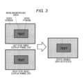
- Fig. 3 is a diagram schematically illustrating an aspect in which a left-eye video and aright-eye video respectively displayed on display panels224 and 225are viewed with the user's both eyes and then fused in the user's brain.
- Fig. 4 is a diagram illustrating an aspect in which a burn-in phenomenon occurs in a display panel that displays a video screen on which a menu screen in which a menu phrase is rendered on a menu background area is superimposed.
- Fig. 1 is a diagram schematically illustrating a configuration of an image display system including a head mount display.
- Fig. 2 is a diagram schematically illustrating an internal configuration of a head mount display 10.
- Fig. 3 is a diagram schematically illustrating an aspect in which a left-eye video and aright-eye video
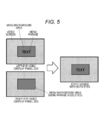
- FIG. 5 is a diagram schematically illustrating an aspect in which video screens on which a menu screen that thins and displays a menu phrase is superimposed are displayed and then are fused in the brain of the user who views the video screens with both eyes.
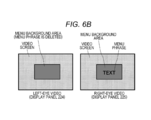
- Fig. 6A is a diagram illustrating an aspect in which a menu phrase is alternately displayed on a menu screen in one of a left-eye video and a right-eye video.
- Fig. 6B is a diagram illustrating an aspect in which a menu phrase is alternately displayed on a menu screen in one of a left-eye video and a right-eye video.
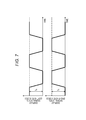
- FIG. 7 is a diagram illustrating a timing chart of a display signal level of a menu phrase in each of a left-eye video and a right-eye video when a menu phrase is alternately deleted from one of a left-eye video and a right-eye video at predetermined time intervals.
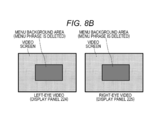
- Fig. 8A is a diagram illustrating an aspect in which menu phrases are displayed on menu screens of both a left-eye video and a right-eye video.
- Fig. 8B is a diagram illustrating an aspect in which menu phrases are deleted from menu screens of both a left-eye video and a right-eye video and thus only menu background areas are displayed.
- FIG. 9 is a timing chart of a display signal level of a menu phrase in each of a left-eye video and a right-eye video when a display and a non-display of menu phrases in a left-eye video and aright-eye video are alternately repeated at predetermined time intervals during a time period in which an OSD screen is displayed.
- Fig. 10 is a timing chart of a display signal level of a menu phrase in each of a left-eye video and aright-eye video when display signals of strong and weak levels of menu phrases in a left-eye video and aright-eye video are alternately switched at predetermined time intervals during a time period in which an OSD screen is displayed.
- Fig. 1 schematically illustrates a configuration of an image display system including a head mount display.
- the system illustrated in Fig. 1 includes a main body of the head mount display10, a Blu-ray disc reproducing device 20 which is a source of viewing content, a high-definition display (for example, a television supporting an HDMI) 30 which is another output destination of reproduction content of the Blu-ray disc reproducing device 20, and a front end box 40 that processes an AV signal output from the Blu-ray disc reproducing device 20.
- a Blu-ray disc reproducing device 20 which is a source of viewing content
- a high-definition display for example, a television supporting an HDMI
- a front end box 40 that processes an AV signal output from the Blu-ray disc reproducing device 20.
- the front end box 40 corresponds to an HDMI repeater that receives an AV signal output from the Blu-ray disc reproducing device 20through an HDMI, performs, for example, signal processing, and outputs the signal processing result through an HDMI.
- the frontend box 40 also functions as a two-output switcher that switches an output destination of the Blu-ray disc reproducing device 20 to either the head mount display10 or the high-definition display 30.In the illustrated example, the front end box 40 has two outputs but may have three or more outputs.
- the frontend box 40 exclusively sets an output destination of an AV signal and gives a priority to an output to the head mount display 10.
- HDMI high-definition multimedia interface
- DVI digital visual interface
- TMDS Transition minimized differential signaling
- the present system conforms to HDMI1.4.
- the Blu-ray disc reproducing device20 is connected to the front end box 40through an HDMI cable, and the frontend box 40 is connected to the high-definition display30through an HDMI cable.
- the front end box 40 can be connected to the head mount display 10 through an HDMI cable, but an AV signal may be serially transferred using any other cable. However, an AV signal and power may be supplied through a single cable that connects the front end box 40withthe head mount display 10, and in this case, the head mount display10 can be supplied with drive power through this cable.
- the head mount display 10 includes left-eye and right-eye display units which are independent of each other.
- an organic EL element may be used as each display unit.
- Each of the left and right display units includes a wide viewing angle optical system of a low strain and high resolution.
- Fig. 2 schematically illustrates an internal configuration of theheadmountdisplay10.
- the head mount display illustrated in Fig. 2 includes a user interface (UI) operating unit 201, a video signal input unit 202, a central control unit 210, and a display control unit 220.
- UI user interface
- the video signal input unit 202 receives a video signal which is reproduced and output from the Blu-ray disc reproducing device 20 through the frontend box 40.
- a left/right video signal generatingunit211 generates a left/right video signal in which a left-eye video signal is mixed with a right-eye video signal from an input video signal, and writes the left/right video signal in a video buffer 212.
- the UI operating unit 201 receives a user's operation made through a button or the like.
- an OSD control unit 213 reads image data of a corresponding menu from a bitmap buffer 214 in response to an UI operation, and generates an OSD screen.
- An OSD display position control unit 215 controls the display position of the OSD screen, and an OSD rendering unit 216writes image data of the OSD screen at a corresponding position of an OSD buffer 217.
- the OSD screen is a menu screen including a menu background area and a menu phrase.
- an image synthesizing unit 218 superimposes the OSD screen written in the OSD buffer 217 on the image data written in the video buffer 212, and outputs the resultant data to the display control unit 220.
- a left/right video signal separating unit221 first separates an input left/right video signal into a left-eye video signal and aright-eye video signal. Then, a left-eye display drive control unit 222performs control such that the left-eye video signal is rendered on a left-eye display panel 224. Further, a right-eye display drive control unit223performs control such that the right-eye video signal is rendered on a right-eye display panel 225.
- each of the display panels 224and 225 may include a display device such as an organic EL element or an LCD.
- Each of the left-eye display panel 224 and the right-eye display panel 225 includes a lens block that enlarges a video.
- Each of the left and right lens blocks includes a combination of a plurality of optical lenses and performs optical processing on a video to be displayed on the displaypanels224 and 225.
- a video displayed on a light-emitting surface of each of the display panels 224 and225 is enlarged while passing through the lens block and then forms a large virtual image on the user's retina.
- a left-eye video and aright-eye video are fused in the brain of the observing user.
- Fig. 3 schematically illustrates an aspect in which a left-eye video and a right-eye video displayed on the display panels 224 and 225, respectively, are viewed with the user's both eyes, and then fused in the user's brain.
- OSD screens are superimposed on the left-eye video and the right-eye video, respectively, near the center of a video screen.
- the OSD screen is a menu screen in which a menu phrase (TEXT) is rendered on a menu background area.
- the menu screens are also fused together with the video screen when viewed with both eyes.
- the display panels224 and 225 include a display device such as an organic EL element or an LCD.
- the display device of this type has a problem in that the burn-in phenomenon is likely to occur in an area having a large brightness difference.
- the burn-in phenomenon occurs in this area.
- the OSD screen is a menu screen in which a menu phrase is rendered on a menu background area
- a brightness difference between still pixels in a boundary between a menu background area and an area for displaying a menu phrase may remain large for a long time, and thus the burn-in phenomenon may remarkably occur.
- the video screen itself, on which the OSD screen is to be superimposed is configured with various video sources such as a moving image and thus changes in a brightness difference between pixels. For this reason, the burn-in phenomenon is reduced to some extent.
- Fig. 4 illustrates an aspect in which the burn-in phenomenon occurs in a display panel that displays a video screen on which a menu screen in which a menu phrase is rendered on a menu background area is superimposed. As illustrated in the right of Fig. 4, the burn-in phenomenon is remarkably observed in a boundary between a menu background area and a menu phrase.
- the video screen is configured with various video sources such as a moving image and changes in a brightness difference between pixels.
- the video screen is unlikely to undergo the burn-in phenomenon, and for this reason, the video screen is displayed without being thinned.
- the menu background area is continuously displayed without being thinned together with the menu phrase. This is because flickering occurs when a display and anon-display are alternately switched even in the menu background area that occupies a relatively large area in the screen.
- Fig. 5 schematically illustrates an aspect in which video screens on which a menu screen that thins and displays a menu phrase is superimposed are displayed on the display panels224 and 225and then are fused in the brain of the user who views the video screens with both eyes.
- a menu screen on which a menu phrase is rendered is superimposed near the screen center of a left-eye video, whereas only a menu background area is displayed near the center of a right-eye video, and a display of a menu phrase is deleted from the menu screen.
- the video screen and the menu background area are common to the left-eye video and the right-eye video.
- the menu screens are also fused together with the video screens, and thus the menu phrase is almost normally viewed.
- Fig. 6A is a diagram illustrating an aspect in which a left-eye video in which a menu screen on which a menu phrase is rendered on a menu back ground area is superimposed near the center of a video screen is displayed at the same time as a right-eye video in which a menu screen including only a menu background area in which a menu phrase is thinned is superimposed near the center of a video screen.
- the video screen and the menu background area are common to the left-eye video and the right-eye video.
- Fig. 6B is a diagram illustrating an aspect in which a left-eye video in which a menu screen including only a menu background area in which a menu phrase is thinned is superimposed near the center of a video screen is displayed at the same time as a right-eye video in which a menu screen on which a menu phrase is rendered on a menu background area is superimposed near the center of a video screen.
- the video screen and the menu background area are common to the left-eye video and the right-eye video.
- an OSD screen display process is activated in response to the user's UI operation on the UI operating unit 201.
- a method of switching a display and anon-display of a menu phrase using the user's operation on the UI operating unit 201 as trigger is considered as a first example of a display method of thinning a menu phrase.
- a menu phrase is alternately deleted from one of left-eye video and a right-eye video each time the UI operating unit201is operated.
- a menu phrase is first displayed only on the left-eye video as illustrated in Fig.6A.
- the menu screens are deleted from both the left-eye video and right-eye video in response to the fact that a specification of a menu ends(not illustrated).
- a menu phrase is displayed only on the right-eye video in turn as illustrated in Fig. 6B.
- This method is a method of switching a video displaying a menu phrase at predetermined time intervals.
- Fig. 7 illustrates a timing chart of a display signal level of a menu phrase in each of a left-eye video and a right-eye video when a menu phrase is alternately deleted from one of a left-eye video and a right-eye video at predetermined time intervals.
- a display signal level current
- a display signal level is set to I A
- a display signal level is set to 0.
- a display of the left and right videos illustrated in Fig. 6A and a display of the left and right videos illustrated in Fig. 6B are alternately repeated at predetermined time intervals.
- Display Method 3 Next, a method of alternately repeating a display and a non-display of menu phrases in a left-eye video and a right-eye video at predetermined time intervals during a time period in which an OSD screen is displayed will be described. Unlike the display method 2, switching operations between a display and anon-display of the menu phrases in the left-eye video and the right-eye video are performed at the same time.
- Fig. 8A illustrates an aspect in which menu phrases are displayed on menu screens of both a left-eye video and a right-eye video.
- Fig. 8B illustrates an aspect in which menu phrases are deleted from menu screens of both a left-eye video and aright-eye video and thus only menu background areas are displayed.
- Fig. 9 illustrates a timing chart of a display signal level of a menu phrase in each of a left-eye video and aright-eye video when a display and a non-display of menu phrases in a left-eye video and a right-eye video are alternately repeated at predetermined time intervals during a time period in which an OSD screen is displayed.
- Display Method 4 A method of alternately switching display signals of strong and weak levels of menu phrases in a left-eye video and a right-eye video at predetermined time intervals during a time period in which an OSD screen is displayed will be described.
- Fig. 10 illustrates a timing chart of a display signal level of a menu phrase in each of a left-eye video and aright-eye video when display signals of strong and weak levels of menu phrases in a left-eye video and aright-eye video are alternately switched at predetermined time intervals during a time period in which an OSD screen is displayed.
- the left-eye video and the right-eye video are fused in the brain of the observing user, and thus the menu phrase is expected to be viewed at desired brightness.
- a display method comprising: displaying an on-screen display image defined by a left-eye video signal and a right-eye video signal, wherein the on-screen display image comprises text and background, and wherein the text is deleted alternately from one of the left-eye video signal and the right-eye video signal.
- each of the left-eye video signal and the right-eye video signal comprises a still image in addition to the on-screen display image.
- each of the left-eye video signal and the right-eye video signal comprises a moving image in addition to the on-screen display image.
- a display method comprising: displaying an on-screen display image defined by a left-eye video signal and a right-eye video signal, wherein the on-screen display image comprises text and background, and wherein the text is thinned relative to the background by alternately reducing a display signal level of the text for one of the left-eye video signal and the right-eye video signal, wherein the display signal level is reduced from a high display signal level, which is below a full display signal level, to a low display signal level.
- the method of (7) wherein when a value of the high display signal level is added to a value of the low display signal level, the sum is equal to a value of the full display signal level.
- (9)An image display system comprising: at least one control unit for generating an on-screen display image defined by a left-eye video signal and aright-eye video signal, wherein the on-screen display image comprises text and background, and wherein the text is deleted alternately from one of the left-eye video signal and the right-eye video signal; a left-eye display panel for displaying the left-eye video signal; and a right-eye display panel for displaying the right-eye video signal.
- an image display system comprising: at least one control unit for generating an on-screen display image defined by a left-eye video signal and aright-eye video signal, wherein the on-screen display image comprises text and background, and wherein the text is thinned relative to the background by alternately reducing a display signal level of the text for one of the left-eye video signal and the right-eye video signal, wherein the display signal level is reduced from a high display signal level, which is below a full display signal level, to a low display signal level; a left-eye display panel for displaying the left-eye video signal; and a right-eye display panel for displaying the right-eye video signal.
- the technology disclosed in this description has been described in connection with the embodiments to which the head mount display is applied.
- the gist of the technology disclosed in this description is not limited to a configuration of a specific head mount display.
- the technology disclosed in this description can be similarly applied to display systems of various types capable of displaying a left-eye video and a right-eye video or a plurality of videos at the same time.
- a device that displays a video is not limited to an LCD or an organic EL element, and the technology disclosed in this description is effective even on various display devices which are likely to undergo the burn-in phenomenon in an area having a large brightness difference.
- Head mount display 20
- Blu-ray disc reproducing device 30
- High-definition display 40
- Frontend box 201
- UI operating unit 202
- Video signal input unit 210
- Central control unit 211
- Left/right video signal generating unit 212
- OSD control unit 214
- Bitmap buffer 215 OSD display position control unit
- OSD rendering unit 217
- OSD buffer 218 Image synthesizing unit 220
- Left/right video signal separating unit 222
- Right-eye display drive control unit 224
- Left-eye display panel 225
- Right-eye display panel 225
Abstract
To appropriately prevent a burn-in phenomenon when a still image such as an OSD screen is displayed on a display panel. When a menu screen is displayed on a video screen in a superimposed manner, a menu phrase in at least one of a left-eye video and a right-eye video is deleted on a menu background area. A time period in which a brightness difference between still pixels in a boundary between a menu background area and a menu phrase remains large is reduced, and thus the occurrence of the burn-in phenomenon can be prevented. However, the menu background area is constantly displayed without being deleted, so that screen flickering does not occur.
Description
The technology disclosed in this description relates to a head mount display which is mounted on a user's head and used to view a video, and a display control method, and more particularly, to a head mount display and a display control method capable of preventing a burn-in phenomenon when a still image such as an OSD screen is displayed on a display panel.
A display device that is mounted on the head and used to view a video, that is, ahead mount display(HMD) has been widely known. The head mount display includes left-eye and right-eye optical units, and is configured to control a visual sense and an auditory sense in conjunction with a headphone. The head mount display configured to completely block the outside world when mounted on the head implements increased virtual reality while viewing a video. Further, the head mount display can project different videos to the left and right eyes, and can provide a 3D image by displaying an image with parallax between the left and right eyes.
For example, a high-resolution display panel including a liquid crystal element or an organic electro-luminescence(EL) element may be used as left-eye and right-eye display units of a head mount display. Further, when an appropriate angle of view is set by an optical system and a multi-channel is reproduced by a headphone, a realistic sensation like when viewed in a movie theater can be reproduced.
In the industry, a display panel configured with a liquid crystal element, an organic EL element, or the like has been known to be likely to undergo the burn-in phenomenon in an area having a large brightness difference. When a still image such as an onscreen display (OSD) screen is rendered to be superimposed on a video screen, an area having a large brightness difference occurs, and thus the burn-in phenomenon occurs in the area.
The head mount display has a limitation to the number of operation buttons mountable to a main body thereof, and thus a user operation using an OSD screen is inevitably required. Thus, even when the display panel of the above-mentioned type is used as the display device of the head mount display, significant consideration needs to be given to prevent the burn-in phenomenon from occurring when an OSD screen is displayed.
For example, an OSD screen used to display a menu includes a menu background area and a menu phrase rendered on the background area. An OSD screen is basically a still image and is likely to have a large brightness difference. For this reason, when an OSD screen is displayed for a long time, the burn-in phenomenon occurs.
A video screen is configured with various video sources such as a moving image, and thus a brightness difference between pixels changes. For this reason, the burn-in phenomenon is reduced to some extent. On the other hand, in a boundary between a menu background area and an area for displaying a menu phrase, when a large brightness difference between still pixels is continued for a long time, the burn-in phenomenon remarkably occurs. Since a menu is often displayed such that the same phrase is repeatedly displayed, the burn-in is easily observed particularly in a boundary portion between the menu background area and a menu phrase.
For example, a liquid crystal display device has been proposed that prevents an afterimage phenomenon, in a state in which display content of the entire screen can be constantly determined, by sequentially moving pixels equally dispersed among pixels configuring a display screen and causing the moved pixels to display black (for example, see Patent Document 1).
Further, an organic light-emitting display device has been proposed that suppresses the burn-in from being observed even when the same image is displayed for a longtime by moving a display position of the entire panel by a predetermined distance at predetermined time intervals (for example, see Patent Document 2).
Furthermore, a video display device has been proposed that prevents the burn-in by a process of lowering brightness of an OSD display (for example, see Patent Document 3).
However, in the above-mentioned related arts, it is difficult to prevent the burn-in phenomenon, particularly, in the boundary portion between the menu background area and the menu phrase. Since a video screen on which an OSD screen is not superimposed is configured with various video sources such as a moving image, the video screen is intrinsically unlikely to undergo the burn-in phenomenon. Nevertheless, when a pixel displaying black on a video screen is inserted, a screen of the video screen becomes dark, and the image quality degrades. Further, when the display position of the entire panel is moved by a predetermined distance at predetermined time intervals, the image quality of the video screen degrades, causing complaints to manufacturers. Furthermore, when the brightness of the OSD display is lowered, the OSD screen is not easily visible.
It is an object of the technology disclosed in this description to provide a head mount display and a display control method, which are excellent and capable of appropriately preventing the burn-in phenomenon from occurring when a still image such as an OSD screen is displayed on a display panel.
It is another object of the technology disclosed in this description to provide ahead mount display and a display control method, which are excellent and capable of appropriately preventing the burn-in phenomenon, particularly in a boundary portion between a menu background area and a menu phrase when a video, in which an OSD screen including the menu background area and the menu phrase is superimposed on a video screen, is displayed on a display panel.
The present disclosure has been made in light of the above problems, and a technology according to claim 1 provides a display method comprising: displaying an on-screen display image defined by a left-eye video signal and a right-eye video signal, wherein the on-screen display image comprises text and background, and wherein the text is deleted alternately from one of the left-eye video signal and the right-eye video signal.
According to a technology according to claim1, wherein the text is deleted in response to a user operation.
According to a technology according to claim1, wherein alternately deleting is performed at predetermined time intervals during a time period in which the on-screen display image is displayed.
According to a technology according to claim1, wherein each of the left-eye video signal and the right-eye video signal comprises a still image in addition to the on-screen display image.
According to a technology according to claim1, wherein each of the left-eye video signal and the right-eye video signal comprises a moving image in addition to the on-screen display image.
Further, a technology according to claim 1,wherein the left-eye video signal is communicated to a left-eye display panel of a head mount display, and the right-eye video signal I communicated to a right-eye display panel of the head mount display.
According to a technology claim 7 provides a display method comprising: displaying an on-screen display image defined by a left-eye video signal and a right-eye video signal, wherein the on-screen display image comprises text and background, and wherein the text is thinned relative to the background by alternately reducing a display signal level of the text for one of the left-eye video signal and the right-eye video signal, wherein the display signal level is reduced from a high display signal level, which is below a full display signal level, to a low display signal level.
According to a technology according to claim7, wherein when a value of the high display signal level is added to a value of the low display signal level, the sum is equal to a value of the full display signal level.
According to a technology claim 9 provides an image display system comprising: at least one control unit for generating an on-screen display image defined by a left-eye video signal and a right-eye video signal, wherein the on-screen display image comprises text and background, and wherein the text is deleted alternately from one of the left-eye video signal and the right-eye video signal;
a left-eye display panel for displaying the left-eye video signal; and
a right-eye display panel for displaying the right-eye video signal.
a left-eye display panel for displaying the left-eye video signal; and
a right-eye display panel for displaying the right-eye video signal.
According to a technology according to claim9, wherein the text is deleted in response to a user operation.
According to the technology disclosed in this description, it is possible to provide ahead mount display and a display control method, which are excellent and capable of appropriately preventing the burn-in phenomenon from occurring when a still image such as an OSD screen is displayed on a display panel.
Further, according to the technology disclosed in this description, it is possible to provide a head mount display and a display control method, which are excellent and capable of appropriately preventing the burn-in phenomenon, particularly in a boundary portion between a menu background area and a menu phrase when a video, in which an OSD screen including the menu background area and the menu phrase is superimposed on a video screen, is displayed on a display panel.
Other objects, features, and advantages of the technology disclosed in this description will become apparent from the detailed description based on embodiments which will be described later and the accompanying drawings.
Hereinafter, embodiments of the technology disclosed in this description will be described in detail with reference to the accompanying drawings.
Fig. 1schematically illustrates a configuration of an image display system including a head mount display. The system illustrated in Fig. 1 includes a main body of the head mount display10, a Blu-ray disc reproducing device 20 which is a source of viewing content, a high-definition display (for example, a television supporting an HDMI) 30 which is another output destination of reproduction content of the Blu-ray disc reproducing device 20, and a front end box 40 that processes an AV signal output from the Blu-ray disc reproducing device 20.
The front end box 40corresponds to an HDMI repeater that receives an AV signal output from the Blu-ray disc reproducing device 20through an HDMI, performs, for example, signal processing, and outputs the signal processing result through an HDMI. The frontend box 40also functions as a two-output switcher that switches an output destination of the Blu-ray disc reproducing device 20 to either the head mount display10 or the high-definition display 30.In the illustrated example, the front end box 40 has two outputs but may have three or more outputs. The frontend box 40 exclusively sets an output destination of an AV signal and gives a priority to an output to the head mount display 10.
The high-definition multimedia interface (HDMI) refers to an interface standard for digital home electronics which is based on a digital visual interface (DVI)and mainly used to transmit a sound and a video. Transition minimized differential signaling (TMDS) is used in a physical layer of the HDMI. For example, the present system conforms to HDMI1.4.
The Blu-ray disc reproducing device20 is connected to the front end box 40through an HDMI cable, and the frontend box 40 is connected to the high-definition display30through an HDMI cable. The front end box 40 can be connected to the head mount display 10 through an HDMI cable, but an AV signal may be serially transferred using any other cable. However, an AV signal and power may be supplied through a single cable that connects the front end box 40withthe head mount display 10, and in this case, the head mount display10 can be supplied with drive power through this cable.
The head mount display 10includes left-eye and right-eye display units which are independent of each other. For example, an organic EL element may be used as each display unit. Each of the left and right display units includes a wide viewing angle optical system of a low strain and high resolution.
Fig. 2schematically illustrates an internal configuration of theheadmountdisplay10. The head mount display illustrated in Fig. 2 includes a user interface (UI) operating unit 201, a video signal input unit 202, a central control unit 210, and a display control unit 220.
The video signal input unit 202receives a video signal which is reproduced and output from the Blu-ray disc reproducing device 20 through the frontend box 40.
Inside the central control unit210, a left/right video signal generatingunit211generates a left/right video signal in which a left-eye video signal is mixed with a right-eye video signal from an input video signal, and writes the left/right video signal in a video buffer 212.
The UI operating unit 201receives a user's operation made through a button or the like. Inside the central control unit 210, an OSD control unit 213 reads image data of a corresponding menu from a bitmap buffer 214 in response to an UI operation, and generates an OSD screen. An OSD display position control unit 215 controls the display position of the OSD screen, and an OSD rendering unit 216writes image data of the OSD screen at a corresponding position of an OSD buffer 217. For example, the OSD screen is a menu screen including a menu background area and a menu phrase.
Then, an image synthesizing unit 218 superimposes the OSD screen written in the OSD buffer 217 on the image data written in the video buffer 212, and outputs the resultant data to the display control unit 220.
Inside the display control unit220, a left/right video signal separating unit221first separates an input left/right video signal into a left-eye video signal and aright-eye video signal. Then, a left-eye display drive control unit 222performs control such that the left-eye video signal is rendered on a left-eye display panel 224. Further, a right-eye display drive control unit223performs control such that the right-eye video signal is rendered on a right-eye display panel 225.For example, each of the display panels 224and 225 may include a display device such as an organic EL element or an LCD. Each of the left-eye display panel 224 and the right-eye display panel 225 includes a lens block that enlarges a video. Each of the left and right lens blocks includes a combination of a plurality of optical lenses and performs optical processing on a video to be displayed on the displaypanels224 and 225. A video displayed on a light-emitting surface of each of the display panels 224 and225 is enlarged while passing through the lens block and then forms a large virtual image on the user's retina. A left-eye video and aright-eye video are fused in the brain of the observing user.
Fig. 3schematically illustrates an aspect in which a left-eye video and a right-eye video displayed on the display panels 224 and 225, respectively, are viewed with the user's both eyes, and then fused in the user's brain. In the illustrated example, OSD screens are superimposed on the left-eye video and the right-eye video, respectively, near the center of a video screen. The OSD screen is a menu screen in which a menu phrase (TEXT) is rendered on a menu background area. The menu screens are also fused together with the video screen when viewed with both eyes.
For example, the display panels224 and 225 include a display device such as an organic EL element or an LCD. However, the display device of this type has a problem in that the burn-in phenomenon is likely to occur in an area having a large brightness difference. For example, when a still image such as the OSD screen is rendered to be superimposed on the video screen, since an area having a large brightness difference is present, the burn-in phenomenon occurs in this area. Particularly, when the OSD screen is a menu screen in which a menu phrase is rendered on a menu background area, a brightness difference between still pixels in a boundary between a menu background area and an area for displaying a menu phrase may remain large for a long time, and thus the burn-in phenomenon may remarkably occur. Meanwhile, the video screen itself, on which the OSD screen is to be superimposed, is configured with various video sources such as a moving image and thus changes in a brightness difference between pixels. For this reason, the burn-in phenomenon is reduced to some extent.
Fig. 4illustrates an aspect in which the burn-in phenomenon occurs in a display panel that displays a video screen on which a menu screen in which a menu phrase is rendered on a menu background area is superimposed. As illustrated in the right of Fig. 4, the burn-in phenomenon is remarkably observed in a boundary between a menu background area and a menu phrase.
In this regard, in the technology disclosed in this description, when a video screen on which a menu screen is superimposed is displayed by the head mount display 10,a menu phrase in at least one of a left-eye video and a right-eye video is thinned and then displayed on a menu background area. As a result, a time period in which a brightness difference between still pixels in a boundary between the menu background area and the menu phrase remains large is reduced, and thus the occurrence of the burn-in phenomenon can be prevented.
The video screen is configured with various video sources such as a moving image and changes in a brightness difference between pixels. Thus, the video screen is unlikely to undergo the burn-in phenomenon, and for this reason, the video screen is displayed without being thinned. Further, the menu background area is continuously displayed without being thinned together with the menu phrase. This is because flickering occurs when a display and anon-display are alternately switched even in the menu background area that occupies a relatively large area in the screen.
Fig. 5schematically illustrates an aspect in which video screens on which a menu screen that thins and displays a menu phrase is superimposed are displayed on the display panels224 and 225and then are fused in the brain of the user who views the video screens with both eyes. In the illustrated example, a menu screen on which a menu phrase is rendered is superimposed near the screen center of a left-eye video, whereas only a menu background area is displayed near the center of a right-eye video, and a display of a menu phrase is deleted from the menu screen. The video screen and the menu background area are common to the left-eye video and the right-eye video. In a state in which the left-eye and right-eye videos are viewed with both eyes, the menu screens are also fused together with the video screens, and thus the menu phrase is almost normally viewed.
Fig. 6Ais a diagram illustrating an aspect in which a left-eye video in which a menu screen on which a menu phrase is rendered on a menu back ground area is superimposed near the center of a video screen is displayed at the same time as a right-eye video in which a menu screen including only a menu background area in which a menu phrase is thinned is superimposed near the center of a video screen. The video screen and the menu background area are common to the left-eye video and the right-eye video.
Fig. 6Bis a diagram illustrating an aspect in which a left-eye video in which a menu screen including only a menu background area in which a menu phrase is thinned is superimposed near the center of a video screen is displayed at the same time as a right-eye video in which a menu screen on which a menu phrase is rendered on a menu background area is superimposed near the center of a video screen. The video screen and the menu background area are common to the left-eye video and the right-eye video.
In a state in which the left and right videos of either of Figs. 6A and 6B are displayed and viewed with both eyes, the menu screens are also fused together with the video screens, and thus the menu phrase is almost normally viewed. When video displays of Figs. 6A and6B are alternately repeated, duty ratios at which the menu phrase is displayed on the menu background in the left and right display panels224 and 225 are 50%, respectively. Thus, degradation of the display panels 224 and 225 caused by the burn-in of the OSD screen display can be prevented by about50%.
There are several display methods of thinning the menu phrase from the menu screen in the left and right videos. Here, several methods of thinning a menu phrase are introduced.
Display Method 1
As described above, an OSD screen display process is activated in response to the user's UI operation on theUI operating unit 201. A method of switching a display and anon-display of a menu phrase using the user's operation on the UI operating unit 201 as trigger is considered as a first example of a display method of thinning a menu phrase. In other words, a menu phrase is alternately deleted from one of left-eye video and a right-eye video each time the UI operating unit201is operated.
As described above, an OSD screen display process is activated in response to the user's UI operation on the
When the UI operating unit 201is operated and thus a corresponding menu screen is displayed, a menu phrase is first displayed only on the left-eye video as illustrated in Fig.6A.
Then, when an operation such as menu selection is performed by the UI operatingunit201, the menu screens are deleted from both the left-eye video and right-eye video in response to the fact that a specification of a menu ends(not illustrated).
Subsequently, when the UI operating unit 201 is operated and thus a corresponding menu screen is displayed, a menu phrase is displayed only on the right-eye video in turn as illustrated in Fig. 6B.
Display Method 2
Next, a method of alternately deleting a menu phrase from one of a left-eye video and aright-eye video at predetermined time intervals during a time period in which an OSD screen is displayed will be described. This method is a method of switching a video displaying a menu phrase at predetermined time intervals.
Next, a method of alternately deleting a menu phrase from one of a left-eye video and aright-eye video at predetermined time intervals during a time period in which an OSD screen is displayed will be described. This method is a method of switching a video displaying a menu phrase at predetermined time intervals.
Fig. 7illustrates a timing chart of a display signal level of a menu phrase in each of a left-eye video and a right-eye video when a menu phrase is alternately deleted from one of a left-eye video and a right-eye video at predetermined time intervals. During a display time period of the menu phrase, a display signal level (current) is set to IA, and during a time period in which the menu phrase is deleted, a display signal level is set to 0.
In this case, a display of the left and right videos illustrated in Fig. 6A and a display of the left and right videos illustrated in Fig. 6B are alternately repeated at predetermined time intervals.
Display Method 3
Next, a method of alternately repeating a display and a non-display of menu phrases in a left-eye video and a right-eye video at predetermined time intervals during a time period in which an OSD screen is displayed will be described. Unlike the display method 2, switching operations between a display and anon-display of the menu phrases in the left-eye video and the right-eye video are performed at the same time.
Next, a method of alternately repeating a display and a non-display of menu phrases in a left-eye video and a right-eye video at predetermined time intervals during a time period in which an OSD screen is displayed will be described. Unlike the display method 2, switching operations between a display and anon-display of the menu phrases in the left-eye video and the right-eye video are performed at the same time.
Fig. 8Aillustrates an aspect in which menu phrases are displayed on menu screens of both a left-eye video and a right-eye video. Fig. 8B illustrates an aspect in which menu phrases are deleted from menu screens of both a left-eye video and aright-eye video and thus only menu background areas are displayed. Fig. 9illustrates a timing chart of a display signal level of a menu phrase in each of a left-eye video and aright-eye video when a display and a non-display of menu phrases in a left-eye video and a right-eye video are alternately repeated at predetermined time intervals during a time period in which an OSD screen is displayed.
Display Method 4
A method of alternately switching display signals of strong and weak levels of menu phrases in a left-eye video and a right-eye video at predetermined time intervals during a time period in which an OSD screen is displayed will be described.
A method of alternately switching display signals of strong and weak levels of menu phrases in a left-eye video and a right-eye video at predetermined time intervals during a time period in which an OSD screen is displayed will be described.
Fig. 10illustrates a timing chart of a display signal level of a menu phrase in each of a left-eye video and aright-eye video when display signals of strong and weak levels of menu phrases in a left-eye video and aright-eye video are alternately switched at predetermined time intervals during a time period in which an OSD screen is displayed.
In this method, under the assumption that a display signal level (current) when a menu phrase is fully displayed is IA, a value of a high display signal level of a menu phrase is set to IH lower than IA, and a value of a low display signal level of a menu phrase is set to IL higher than 0, so that a relation of "IA = IH +IL" is established. In this case, a menu phrase is displayed with either of the display signal levels IH and IL in each of a left-eye video and a right-eye video, and thus a menu phrase is displayed darker than when a menu phrase is displayed in any one video with the display signal level IA. However, when the display signal level of the menu phrase in the left-eye video is added to the display signal level of the menu phrase in the right-eye video, the resultant display signal level is constantly IA =IH + IL. Thus, the left-eye video and the right-eye video are fused in the brain of the observing user, and thus the menu phrase is expected to be viewed at desired brightness.
The technology disclosed in this description may have the following configurations.
(1)A display method comprising: displaying an on-screen display image defined by a left-eye video signal and a right-eye video signal, wherein the on-screen display image comprises text and background, and wherein the text is deleted alternately from one of the left-eye video signal and the right-eye video signal.
(2)The method of (1), wherein the text is deleted in response to a user operation.
(3)The method of (1), wherein alternately deleting is performed at predetermined time intervals during a time period in which the on-screen display image is displayed.
(4)The method of (1), wherein each of the left-eye video signal and the right-eye video signal comprises a still image in addition to the on-screen display image.
(5)The method of (1), wherein each of the left-eye video signal and the right-eye video signal comprises a moving image in addition to the on-screen display image.
(6)The method (1), wherein the left-eye video signal is communicated to a left-eye display panel of a head mount display, and the right-eye video signal is communicated to a right-eye display panel of the head mount display.
(7)A display method comprising:
displaying an on-screen display image defined by a left-eye video signal and a right-eye video signal, wherein the on-screen display image comprises text and background, and wherein the text is thinned relative to the background by alternately reducing a display signal level of the text for one of the left-eye video signal and the right-eye video signal, wherein the display signal level is reduced from a high display signal level, which is below a full display signal level, to a low display signal level.
(8)The method of (7), wherein when a value of the high display signal level is added to a value of the low display signal level, the sum is equal to a value of the full display signal level.
(9)An image display system comprising:
at least one control unit for generating an on-screen display image defined by a left-eye video signal and aright-eye video signal, wherein the on-screen display image comprises text and background, and wherein the text is deleted alternately from one of the left-eye video signal and the right-eye video signal;
a left-eye display panel for displaying the left-eye video signal; and
a right-eye display panel for displaying the right-eye video signal.
(10)The system of (9), wherein the text is deleted in response to a user operation.
(11)The system of (9), wherein alternately deleting is performed at predetermined time intervals during a time period in which the on-screen display image is displayed.
(12)The system of (9), wherein the display control unit, the left-eye display panel, and the right-eye display panel are included within ahead mount display.
(13)An image display system comprising:
at least one control unit for generating an on-screen display image defined by a left-eye video signal and aright-eye video signal, wherein the on-screen display image comprises text and background, and wherein the text is thinned relative to the background by alternately reducing a display signal level of the text for one of the left-eye video signal and the right-eye video signal, wherein the display signal level is reduced from a high display signal level, which is below a full display signal level, to a low display signal level;
a left-eye display panel for displaying the left-eye video signal; and
a right-eye display panel for displaying the right-eye video signal.
(14)The system of (13), wherein when a value of the high display signal level is added to a value of the low display signal level, the sum is equal to a value of the full display signal level.
(15)The system of (13), wherein the display control unit, the left-eye display panel, and the right-eye display panel are included within ahead mount display.
(16)A non-transitory computer-readable medium having stored thereon a computer readable program for implementing a display method, the display method comprising:
displaying an on-screen display image defined by a left-eye video signal and a right-eye video signal, wherein the on-screen display image comprises text and background, and wherein the text is deleted alternately from one of the left-eye video signal and the right-eye video signal.
(17)A non-transitory computer-readable medium having stored thereon a computer readable program for implementing a display method, the display method comprising:
displaying an on-screen display image defined by a left-eye video signal and a right-eye video signal, wherein the on-screen display image comprises text and background, and wherein the text is thinned relative to the background by alternately reducing a display signal level of the text for one of the left-eye video signal and the right-eye video signal, wherein the display signal level is reduced from a high display signal level, which is below a full display signal level, to a low display signal level.
The technology disclosed in this description has been described above in detail with reference to the specific embodiments. However, it is obvious that those skilled in the art can make modification or substitution of the embodiments in a range not departing from the gist of the technology disclosed in this description.
In this description, the technology disclosed in this description has been described in connection with the embodiments to which the head mount display is applied. However, the gist of the technology disclosed in this description is not limited to a configuration of a specific head mount display. The technology disclosed in this description can be similarly applied to display systems of various types capable of displaying a left-eye video and a right-eye video or a plurality of videos at the same time. Further, a device that displays a video is not limited to an LCD or an organic EL element, and the technology disclosed in this description is effective even on various display devices which are likely to undergo the burn-in phenomenon in an area having a large brightness difference.
In short, the technology disclosed in this description has been described by way of illustration, and thus the content described in this description is not to be interpreted as a limitation. It is necessary to take claims into consideration in order to determine the gist of the technology disclosed in this description.
10 Head mount display
20 Blu-ray disc reproducing device
30 High-definition display
40 Frontend box
201 UI operating unit
202 Video signal input unit
210 Central control unit
211 Left/right video signal generating unit
212 Video buffer
213 OSD control unit
214 Bitmap buffer
215 OSD display position control unit
216 OSD rendering unit
217 OSD buffer
218 Image synthesizing unit
220 Display control unit
221 Left/right video signal separating unit
222 Left-eye display drive control unit
223 Right-eye display drive control unit
224 Left-eye display panel
225 Right-eye display panel
Claims (17)
- A display method comprising:
displaying an on-screen display image defined by a left-eye video signal and a right-eye video signal, wherein the on-screen display image comprises text and background, and wherein the text is deleted alternately from one of the left-eye video signal and the right-eye video signal. - The method as recited in claim 1, wherein the text is deleted in response to a user operation.
- The method as recited in claim 1, wherein alternately deleting is performed at predetermined time intervals during a time period in which the on-screen display image is displayed.
- The method as recited in claim 1, wherein each of the left-eye video signal and the right-eye video signal comprises a still image in addition to the on-screen display image.
- The method as recited in claim 1, wherein each of the left-eye video signal and the right-eye video signal comprises a moving image in addition to the on-screen display image.
- The method as recited in claim 1, wherein the left-eye video signal is communicated to a left-eye display panel of a head mount display, and the right-eye video signal is communicated to a right-eye display panel of the head mount display.
- A display method comprising:
displaying an on-screen display image defined by a left-eye video signal and a right-eye video signal, wherein the on-screen display image comprises text and background, and wherein the text is thinned relative to the background by alternately reducing a display signal level of the text for one of the left-eye video signal and the right-eye video signal, wherein the display signal level is reduced from a high display signal level, which is below a full display signal level, to a low display signal level. - The method as recited in claim 7, wherein when a value of the high display signal level is added to a value of the low display signal level, the sum is equal to a value of the full display signal level.
- An image display system comprising:
at least one control unit for generating an on-screen display image defined by a left-eye video signal and aright-eye video signal, wherein the on-screen display image comprises text and background, and wherein the text is deleted alternately from one of the left-eye video signal and the right-eye video signal;
a left-eye display panel for displaying the left-eye video signal; and
a right-eye display panel for displaying the right-eye video signal. - The system as recited in claim 9, wherein the text is deleted in response to a user operation.
- The system recited in claim 9, wherein alternately deleting is performed at predetermined time intervals during a time period in which the on-screen display image is displayed.
- The system as recited in claim 9, wherein the display control unit, the left-eye display panel, and the right-eye display panel are included within a head mount display.
- An image display system comprising:
at least one control unit for generating an on-screen display image defined by a left-eye video signal and aright-eye video signal, wherein the on-screen display image comprises text and background, and wherein the text is thinned relative to the background by alternately reducing a display signal level of the text for one of the left-eye video signal and the right-eye video signal, wherein the display signal level is reduced from a high display signal level, which is below a full display signal level, to a low display signal level;
a left-eye display panel for displaying the left-eye video signal; and
a right-eye display panel for displaying the right-eye video signal. - The system as recited in claim 13, wherein when a value of the high display signal level is added to a value of the low display signal level, the sum is equal to a value of the full display signal level.
- The system as recited in claim 13, wherein the display control unit, the left-eye display panel, and the right-eye display panel are included within a head mount display.
- A non-transitory computer-readable medium having stored thereon a computer readable program for implementing a display method, the display method comprising:
displaying an on-screen display image defined by a left-eye video signal and a right-eye video signal, wherein the on-screen display image comprises text and background, and wherein the text is deleted alternately from one of the left-eye video signal and the right-eye video signal. - A non-transitory computer-readable medium having stored thereon a computer readable program for implementing a display method, the display method comprising:
displaying an on-screen display image defined by a left-eye video signal and a right-eye video signal, wherein the on-screen display image comprises text and background, and wherein the text is thinned relative to the background by alternately reducing a display signal level of the text for one of the left-eye video signal and the right-eye video signal, wherein the display signal level is reduced from a high display signal level, which is below a full display signal level, to a low display signal level.
Priority Applications (3)
| Application Number | Priority Date | Filing Date | Title |
|---|---|---|---|
| EP12753593.8A EP2748668A1 (en) | 2011-08-24 | 2012-08-17 | Head mount display and display control method |
| US14/238,933 US9813697B2 (en) | 2011-08-24 | 2012-08-17 | Head mount display and display control method |
| CN201280039990.9A CN103733116B (en) | 2011-08-24 | 2012-08-17 | Head mounted display and display control method |
Applications Claiming Priority (2)
| Application Number | Priority Date | Filing Date | Title |
|---|---|---|---|
| JP2011182323A JP5862112B2 (en) | 2011-08-24 | 2011-08-24 | Head mounted display and display control method |
| JP2011-182323 | 2011-08-24 |
Publications (1)
| Publication Number | Publication Date |
|---|---|
| WO2013027380A1 true WO2013027380A1 (en) | 2013-02-28 |
Family
ID=46763152
Family Applications (1)
| Application Number | Title | Priority Date | Filing Date |
|---|---|---|---|
| PCT/JP2012/005194 WO2013027380A1 (en) | 2011-08-24 | 2012-08-17 | Head mount display and display control method |
Country Status (5)
| Country | Link |
|---|---|
| US (1) | US9813697B2 (en) |
| EP (1) | EP2748668A1 (en) |
| JP (1) | JP5862112B2 (en) |
| CN (1) | CN103733116B (en) |
| WO (1) | WO2013027380A1 (en) |
Cited By (1)
| Publication number | Priority date | Publication date | Assignee | Title |
|---|---|---|---|---|
| US10911734B2 (en) | 2015-12-28 | 2021-02-02 | Lg Display Co., Ltd. | Display device for personal immersive device |
Families Citing this family (8)
| Publication number | Priority date | Publication date | Assignee | Title |
|---|---|---|---|---|
| JP2013044913A (en) * | 2011-08-24 | 2013-03-04 | Sony Corp | Display device and display control method |
| TWI571655B (en) * | 2014-08-22 | 2017-02-21 | 財團法人資訊工業策進會 | Display method and display device |
| CN105657485A (en) * | 2015-08-21 | 2016-06-08 | 乐视致新电子科技(天津)有限公司 | Audio/video playing equipment |
| KR101747268B1 (en) * | 2015-11-30 | 2017-06-14 | 엘지디스플레이 주식회사 | Organic light emitting display device and head mounted display including the same |
| JP6725999B2 (en) * | 2016-03-01 | 2020-07-22 | キヤノン株式会社 | Information processing apparatus, information processing apparatus control method, and program |
| US10488920B2 (en) * | 2017-06-02 | 2019-11-26 | Htc Corporation | Immersive headset system and control method thereof |
| TWI673645B (en) * | 2018-11-27 | 2019-10-01 | 技嘉科技股份有限公司 | Computer system, display apparatus, and display method of an on-screen-display interface |
| JP7243193B2 (en) * | 2019-01-10 | 2023-03-22 | セイコーエプソン株式会社 | Display system, display system control method, information processing device, and information processing device control program |
Citations (6)
| Publication number | Priority date | Publication date | Assignee | Title |
|---|---|---|---|---|
| US20050190258A1 (en) * | 1999-01-21 | 2005-09-01 | Mel Siegel | 3-D imaging arrangements |
| JP2007304318A (en) | 2006-05-11 | 2007-11-22 | Hitachi Ltd | Organic light emitting display device and its display control method |
| US20080170274A1 (en) * | 2007-01-12 | 2008-07-17 | Samsung Electronics Co., Ltd | Image apparatus for processing 3d images and method of controlling the same |
| JP2009134188A (en) | 2007-11-30 | 2009-06-18 | Sharp Corp | Liquid crystal display device and display method |
| JP2011081178A (en) | 2009-10-07 | 2011-04-21 | Sharp Corp | Video display device |
| US20110193947A1 (en) * | 2010-02-08 | 2011-08-11 | Chien-Chou Chen | Liquid crystal display system which adjusts backlight to generate a three-dimensional image effect and method thereof |
Family Cites Families (33)
| Publication number | Priority date | Publication date | Assignee | Title |
|---|---|---|---|---|
| KR960008753B1 (en) * | 1993-09-25 | 1996-06-29 | Samsung Electronics Co Ltd | On screen display circuit |
| KR100357537B1 (en) * | 1997-07-02 | 2003-02-11 | 삼성전자 주식회사 | Apparatus and method for controlling osd in the case of video mute |
| JPH11338448A (en) * | 1998-04-27 | 1999-12-10 | Samsung Electronics Co Ltd | Outputting method and device for on-screen display image plane |
| US6262772B1 (en) * | 1998-11-23 | 2001-07-17 | Philips Electronics North America Corporation | Method and apparatus for preventing display screen burn-in |
| US20010035874A1 (en) * | 2000-04-27 | 2001-11-01 | Pelco | Method for prolonging CRT screen life by reduced phosphor burning |
| US20020015029A1 (en) * | 2000-06-29 | 2002-02-07 | Toru Mizushima | On-screen display device |
| JP2003098471A (en) * | 2001-09-25 | 2003-04-03 | Olympus Optical Co Ltd | Head-mount type video display device |
| US20080177994A1 (en) * | 2003-01-12 | 2008-07-24 | Yaron Mayer | System and method for improving the efficiency, comfort, and/or reliability in Operating Systems, such as for example Windows |
| JP2005197991A (en) * | 2004-01-07 | 2005-07-21 | Orion Denki Kk | On-screen display device |
| JP4037405B2 (en) * | 2004-12-09 | 2008-01-23 | 株式会社アステックコーポレーション | Display seizure prevention device |
| JP4700366B2 (en) * | 2005-02-14 | 2011-06-15 | 三洋電機株式会社 | On-screen display circuit |
| JP4756892B2 (en) * | 2005-04-01 | 2011-08-24 | キヤノン株式会社 | Image processing device |
| KR100721909B1 (en) * | 2005-08-31 | 2007-05-28 | 삼성전자주식회사 | Display apparatus and method for eliminating an image sticking thereof |
| KR101217226B1 (en) * | 2006-01-27 | 2012-12-31 | 삼성전자주식회사 | Display device capable of reducing afterimage and afterimage reduction method thereof |
| US7663663B2 (en) * | 2006-04-28 | 2010-02-16 | Nvidia Corporation | Burn-in control |
| JP2007333997A (en) * | 2006-06-15 | 2007-12-27 | Sony Corp | Display controller, display device, terminal device, display control method and computer program |
| JPWO2009028160A1 (en) * | 2007-08-24 | 2010-11-25 | パナソニック株式会社 | Receiving apparatus and receiving method |
| JP5211793B2 (en) * | 2008-03-25 | 2013-06-12 | 富士通モバイルコミュニケーションズ株式会社 | Mobile phone |
| US9124870B2 (en) * | 2008-08-20 | 2015-09-01 | Samsung Electronics Co., Ltd. | Three-dimensional video apparatus and method providing on screen display applied thereto |
| WO2010032399A1 (en) * | 2008-09-18 | 2010-03-25 | パナソニック株式会社 | Stereoscopic video reproduction device and stereoscopic video reproduction device |
| TWI404041B (en) * | 2008-12-01 | 2013-08-01 | Mstar Semiconductor Inc | Automatic osd adjusting device and method |
| US8872900B2 (en) * | 2009-06-26 | 2014-10-28 | Lg Electronics Inc. | Image display apparatus and method for operating the same |
| JP5276536B2 (en) * | 2009-07-16 | 2013-08-28 | 富士フイルム株式会社 | 3D image display apparatus and 3D image display method |
| JP2011053468A (en) * | 2009-09-02 | 2011-03-17 | Sony Corp | Video/character simultaneous display device, and head-mounted display |
| KR20110057629A (en) * | 2009-11-24 | 2011-06-01 | 엘지전자 주식회사 | A method for providing an user interface and a digital broadcast receiver |
| KR101424314B1 (en) * | 2010-03-22 | 2014-08-04 | 엘지디스플레이 주식회사 | Stereoscopic Image Display Device |
| US20110255003A1 (en) * | 2010-04-16 | 2011-10-20 | The Directv Group, Inc. | Method and apparatus for presenting on-screen graphics in a frame-compatible 3d format |
| KR101699738B1 (en) * | 2010-04-30 | 2017-02-13 | 엘지전자 주식회사 | Operating Method for Image Display Device and Shutter Glass for the Image Display Device |
| KR20110130708A (en) * | 2010-05-28 | 2011-12-06 | 삼성전자주식회사 | 3d glasses and 3d display apparatus |
| KR101435594B1 (en) * | 2010-05-31 | 2014-08-29 | 삼성전자주식회사 | Display apparatus and display mehod thereof |
| JP5505637B2 (en) * | 2010-06-24 | 2014-05-28 | ソニー株式会社 | Stereoscopic display device and display method of stereoscopic display device |
| US9715742B2 (en) * | 2010-10-07 | 2017-07-25 | Lg Electronics Inc. | Method for producing advertisement content using a display device and display device for same |
| JP2013044913A (en) * | 2011-08-24 | 2013-03-04 | Sony Corp | Display device and display control method |
-
2011
- 2011-08-24 JP JP2011182323A patent/JP5862112B2/en active Active
-
2012
- 2012-08-17 WO PCT/JP2012/005194 patent/WO2013027380A1/en active Application Filing
- 2012-08-17 EP EP12753593.8A patent/EP2748668A1/en not_active Withdrawn
- 2012-08-17 US US14/238,933 patent/US9813697B2/en active Active
- 2012-08-17 CN CN201280039990.9A patent/CN103733116B/en active Active
Patent Citations (6)
| Publication number | Priority date | Publication date | Assignee | Title |
|---|---|---|---|---|
| US20050190258A1 (en) * | 1999-01-21 | 2005-09-01 | Mel Siegel | 3-D imaging arrangements |
| JP2007304318A (en) | 2006-05-11 | 2007-11-22 | Hitachi Ltd | Organic light emitting display device and its display control method |
| US20080170274A1 (en) * | 2007-01-12 | 2008-07-17 | Samsung Electronics Co., Ltd | Image apparatus for processing 3d images and method of controlling the same |
| JP2009134188A (en) | 2007-11-30 | 2009-06-18 | Sharp Corp | Liquid crystal display device and display method |
| JP2011081178A (en) | 2009-10-07 | 2011-04-21 | Sharp Corp | Video display device |
| US20110193947A1 (en) * | 2010-02-08 | 2011-08-11 | Chien-Chou Chen | Liquid crystal display system which adjusts backlight to generate a three-dimensional image effect and method thereof |
Cited By (2)
| Publication number | Priority date | Publication date | Assignee | Title |
|---|---|---|---|---|
| US10911734B2 (en) | 2015-12-28 | 2021-02-02 | Lg Display Co., Ltd. | Display device for personal immersive device |
| EP3188175B1 (en) * | 2015-12-28 | 2021-04-07 | LG Display Co., Ltd. | Display device for personal immersive device |
Also Published As
| Publication number | Publication date |
|---|---|
| EP2748668A1 (en) | 2014-07-02 |
| CN103733116B (en) | 2016-10-19 |
| JP2013044914A (en) | 2013-03-04 |
| JP5862112B2 (en) | 2016-02-16 |
| US9813697B2 (en) | 2017-11-07 |
| CN103733116A (en) | 2014-04-16 |
| US20140198193A1 (en) | 2014-07-17 |
Similar Documents
| Publication | Publication Date | Title |
|---|---|---|
| US9813697B2 (en) | Head mount display and display control method | |
| US20140198192A1 (en) | Display device and display control method | |
| US8564642B2 (en) | Communication method, communication system, transmission method, transmission apparatus, receiving method and receiving apparatus | |
| US9117396B2 (en) | Three-dimensional image playback method and three-dimensional image playback apparatus | |
| US20130050065A1 (en) | Head-mounted display, and display control method | |
| JP2013192193A (en) | Display device, image processing device, image processing method, and computer program | |
| US20110279450A1 (en) | Three dimensional (3d) image display apparatus, and driving method thereof | |
| JP2011216937A (en) | Stereoscopic image display device | |
| US20130127816A1 (en) | Display apparatus and driving method thereof | |
| JP5100873B1 (en) | Crosstalk correction amount evaluation apparatus and crosstalk correction amount evaluation method | |
| EP2552119A1 (en) | Display device and display method and | |
| KR20130070592A (en) | Data transmission system | |
| US20130063420A1 (en) | Stereoscopic Image Display Method, Stereoscopic Image Driving Method, and Stereoscopic Image Display System | |
| KR20130118178A (en) | Display device and method compressing and transmitting data thereof | |
| KR101992161B1 (en) | Stereoscopic image display and polarity control method thereof | |
| KR102526039B1 (en) | Autostereoscopic image display and driving method thereof | |
| KR20150038954A (en) | Image processing device and method for autostereoscopic image display | |
| KR102275491B1 (en) | Crosstalk reduction method and device, and multi-view autostereoscopic image display using the same | |
| TWI406559B (en) | Display method and computer readable medium performing thereof | |
| JP2013085045A (en) | Video display system, video supply device, and display device | |
| KR102080611B1 (en) | Device and method of generating a new image for multi-view autostereoscopic image display | |
| EP2863636A1 (en) | 3D display device and method | |
| TW201306558A (en) | Apparatus and method for 3-D display control | |
| KR20140017226A (en) | Image data generating method and stereoscopic image display using the same | |
| JP2013021427A (en) | Video device |
Legal Events
| Date | Code | Title | Description |
|---|---|---|---|
| 121 | Ep: the epo has been informed by wipo that ep was designated in this application |
Ref document number: 12753593 Country of ref document: EP Kind code of ref document: A1 |
|
| WWE | Wipo information: entry into national phase |
Ref document number: 14238933 Country of ref document: US |
|
| NENP | Non-entry into the national phase |
Ref country code: DE |