WO2013011967A1 - Internal combustion engine - Google Patents
Internal combustion engine Download PDFInfo
- Publication number
- WO2013011967A1 WO2013011967A1 PCT/JP2012/068010 JP2012068010W WO2013011967A1 WO 2013011967 A1 WO2013011967 A1 WO 2013011967A1 JP 2012068010 W JP2012068010 W JP 2012068010W WO 2013011967 A1 WO2013011967 A1 WO 2013011967A1
- Authority
- WO
- WIPO (PCT)
- Prior art keywords
- combustion chamber
- electromagnetic wave
- combustion engine
- internal combustion
- fuel mixture
- Prior art date
Links
Images


Classifications
-
- F—MECHANICAL ENGINEERING; LIGHTING; HEATING; WEAPONS; BLASTING
- F02—COMBUSTION ENGINES; HOT-GAS OR COMBUSTION-PRODUCT ENGINE PLANTS
- F02P—IGNITION, OTHER THAN COMPRESSION IGNITION, FOR INTERNAL-COMBUSTION ENGINES; TESTING OF IGNITION TIMING IN COMPRESSION-IGNITION ENGINES
- F02P19/00—Incandescent ignition, e.g. during starting of internal combustion engines; Combination of incandescent and spark ignition
-
- F—MECHANICAL ENGINEERING; LIGHTING; HEATING; WEAPONS; BLASTING
- F02—COMBUSTION ENGINES; HOT-GAS OR COMBUSTION-PRODUCT ENGINE PLANTS
- F02P—IGNITION, OTHER THAN COMPRESSION IGNITION, FOR INTERNAL-COMBUSTION ENGINES; TESTING OF IGNITION TIMING IN COMPRESSION-IGNITION ENGINES
- F02P3/00—Other installations
- F02P3/01—Electric spark ignition installations without subsequent energy storage, i.e. energy supplied by an electrical oscillator
-
- F—MECHANICAL ENGINEERING; LIGHTING; HEATING; WEAPONS; BLASTING
- F02—COMBUSTION ENGINES; HOT-GAS OR COMBUSTION-PRODUCT ENGINE PLANTS
- F02P—IGNITION, OTHER THAN COMPRESSION IGNITION, FOR INTERNAL-COMBUSTION ENGINES; TESTING OF IGNITION TIMING IN COMPRESSION-IGNITION ENGINES
- F02P23/00—Other ignition
- F02P23/04—Other physical ignition means, e.g. using laser rays
-
- H—ELECTRICITY
- H05—ELECTRIC TECHNIQUES NOT OTHERWISE PROVIDED FOR
- H05H—PLASMA TECHNIQUE; PRODUCTION OF ACCELERATED ELECTRICALLY-CHARGED PARTICLES OR OF NEUTRONS; PRODUCTION OR ACCELERATION OF NEUTRAL MOLECULAR OR ATOMIC BEAMS
- H05H1/00—Generating plasma; Handling plasma
- H05H1/24—Generating plasma
- H05H1/46—Generating plasma using applied electromagnetic fields, e.g. high frequency or microwave energy
- H05H1/461—Microwave discharges
- H05H1/463—Microwave discharges using antennas or applicators
Definitions
- the present invention relates to an internal combustion engine that promotes combustion of an air-fuel mixture in a combustion chamber using electromagnetic waves.
- the internal combustion engine described in Japanese Patent Application Laid-Open No. 2007-113570 includes an ignition device that emits microwaves to a combustion chamber before and after ignition of an air-fuel mixture to generate plasma discharge.
- the ignition device creates a local plasma using the discharge of the ignition plug so that the plasma is generated in a high pressure field, and this plasma is grown by the microwave. Local plasma is generated in the discharge gap between the tip of the anode terminal and the ground terminal.
- the resonance frequency of the combustion chamber changes depending on the operation state of the internal combustion engine and the propagation state of the flame after ignition of the air-fuel mixture. For this reason, in the conventional internal combustion engine, even if electromagnetic waves are radiated to the combustion chamber during the propagation of the flame, there is a possibility that the propagation speed of the flame cannot be improved appropriately.
- the present invention has been made in view of such points, and an object thereof is to effectively use energy of electromagnetic waves in a combustion chamber in an internal combustion engine that promotes combustion of an air-fuel mixture in the combustion chamber using electromagnetic waves. Improves flame propagation speed.
- a first invention includes a combustion cycle in which an internal combustion engine body having a combustion chamber formed therein and an ignition device that ignites an air-fuel mixture in the combustion chamber, and the air-fuel mixture is ignited by the ignition device to burn the air-fuel mixture.
- an internal combustion engine that is repeatedly performed, and an electromagnetic wave emission device that radiates electromagnetic waves to the combustion chamber during propagation of a flame after the air-fuel mixture is ignited; and Control means for controlling the frequency of the electromagnetic wave radiated to the combustion chamber by the electromagnetic wave radiation device in consideration of the resonance frequency.
- the frequency of the electromagnetic wave radiated to the combustion chamber is controlled in consideration of the resonance frequency of the combustion chamber in accordance with the operating state of the internal combustion engine body. For this reason, the electromagnetic wave radiated to the combustion chamber during the propagation of the flame appropriately resonates.
- a second invention includes an internal combustion engine body having a combustion chamber formed therein and an ignition device that ignites an air-fuel mixture in the combustion chamber, and ignites the air-fuel mixture by the ignition device to burn the air-fuel mixture.
- an internal combustion engine that is repeatedly performed, and an electromagnetic wave radiation device that radiates electromagnetic waves to the combustion chamber during propagation of a flame after the mixture is ignited, and a resonance frequency of the combustion chamber according to the propagation state of the flame
- the electromagnetic wave emission device includes control means for controlling the frequency of the electromagnetic wave radiated to the combustion chamber.
- the frequency of the electromagnetic wave radiated to the combustion chamber is controlled in consideration of the resonance frequency of the combustion chamber according to the propagation state of the flame. For this reason, the electromagnetic wave radiated to the combustion chamber during the propagation of the flame appropriately resonates.
- the frequency of the electromagnetic wave radiated to the combustion chamber is controlled so that the electromagnetic wave appropriately resonates in the combustion chamber during the propagation of the flame. Therefore, the propagation speed of the flame can be improved by effectively using the electromagnetic wave energy in the combustion chamber.
- FIG. 1 is a longitudinal sectional view of an internal combustion engine according to an embodiment. It is a front view of the ceiling surface of the combustion chamber of the internal combustion engine which concerns on embodiment. It is a block diagram of the ignition device and electromagnetic wave radiation device concerning an embodiment. It is a schematic block diagram of the radiation antenna which concerns on embodiment. It is a longitudinal cross-sectional view of the internal combustion engine which concerns on the modification 2 of embodiment.
- the present embodiment is an internal combustion engine 10 according to the present invention.
- the internal combustion engine 10 is a reciprocating type internal combustion engine in which a piston 23 reciprocates.
- the internal combustion engine 10 includes an internal combustion engine body 11, an ignition device 12, an electromagnetic wave emission device 13, and a control device 35. In the internal combustion engine 10, a combustion cycle in which the air-fuel mixture is ignited by the ignition device 12 and the air-fuel mixture is combusted is repeatedly performed.
- -Internal combustion engine body
- the internal combustion engine main body 11 includes a cylinder block 21, a cylinder head 22, and a piston 23 as shown in FIG.
- a plurality of cylinders 24 having a circular cross section are formed in the cylinder block 21.
- a piston 23 is provided in each cylinder 24 so as to reciprocate.
- the piston 23 is connected to the crankshaft via a connecting rod (not shown).
- the crankshaft is rotatably supported by the cylinder block 21.
- the cylinder head 22 is placed on the cylinder block 21 with the gasket 18 in between.
- the cylinder head 22, together with the cylinder 24, the piston 23, and the gasket 18, constitutes a partition member that partitions the combustion chamber 20 having a circular cross section.
- the diameter of the combustion chamber 20 is, for example, about half the wavelength of the microwave that the electromagnetic wave emission device 13 radiates to the combustion chamber 20.
- the cylinder head 22 is provided with one spark plug 40 that constitutes a part of the ignition device 12 for each cylinder 24.
- the tip exposed to the combustion chamber 20 is positioned at the center of the ceiling surface 51 of the combustion chamber 20 (the surface exposed to the combustion chamber 20 in the cylinder head 22).
- the outer periphery of the distal end portion of the spark plug 40 is circular as viewed from the axial direction.
- a center electrode 40 a and a ground electrode 40 b are provided at the tip of the spark plug 40.
- a discharge gap is formed between the tip of the center electrode 40a and the tip of the ground electrode 40b.
- An intake port 25 and an exhaust port 26 are formed in the cylinder head 22 for each cylinder 24.
- the intake port 25 is provided with an intake valve 27 that opens and closes an intake side opening 25a of the intake port 25, and an injector 29 that injects fuel.
- the exhaust port 26 is provided with an exhaust valve 28 for opening and closing the exhaust side opening 26 a of the exhaust port 26.
- the intake port 25 is designed so that a strong tumble flow is formed in the combustion chamber 20.
- each ignition device 12 is provided for each combustion chamber 20. As shown in FIG. 3, each ignition device 12 includes an ignition coil 14 that outputs a high voltage pulse, and an ignition plug 40 that is supplied with the high voltage pulse output from the ignition coil 14.
- the ignition coil 14 is connected to a DC power source (not shown).
- the ignition coil 14 boosts the voltage applied from the DC power supply, and outputs the boosted high voltage pulse to the center electrode 40 a of the spark plug 40.
- the spark plug 40 when a high voltage pulse is applied to the center electrode 40a, dielectric breakdown occurs in the discharge gap and spark discharge occurs. A discharge plasma is generated in the discharge path of the spark discharge. A negative voltage is applied to the center electrode 40a as a high voltage pulse.
- the ignition device 12 may include a plasma expansion unit that supplies electric energy to the discharge plasma to expand the discharge plasma.
- a plasma expansion part expands a spark discharge by supplying high frequency (for example, microwave) energy to discharge plasma, for example. According to the plasma expansion part, it is possible to improve the stability of ignition with respect to a lean air-fuel mixture.
- the electromagnetic wave emission device 13 may be used as the plasma expansion unit.
- the electromagnetic wave radiation device 13 includes an electromagnetic wave generator 31, an electromagnetic wave switch 32, and a radiation antenna 16.
- the electromagnetic wave generation device 31 and the electromagnetic wave switch 32 are provided one by one, and the radiation antenna 16 is provided for each combustion chamber 20.
- the electromagnetic wave generator 31 When receiving the electromagnetic wave drive signal from the control device 35, the electromagnetic wave generator 31 repeatedly outputs a microwave pulse at a predetermined duty ratio.
- the electromagnetic wave drive signal is a pulse signal.
- the electromagnetic wave generator 31 repeatedly outputs the microwave pulse over the time of the pulse width of the electromagnetic wave drive signal.
- a semiconductor oscillator In the electromagnetic wave generator 31, a semiconductor oscillator generates a microwave pulse. In place of the semiconductor oscillator, another oscillator such as a magnetron may be used.
- the electromagnetic wave switch 32 includes one input terminal and a plurality of output terminals provided for each radiation antenna 16.
- the input terminal is connected to the electromagnetic wave generator 31.
- Each output terminal is connected to a corresponding radiation antenna 16.
- the electromagnetic wave switch 32 is controlled by the control device 35 and sequentially switches the supply destination of the microwaves output from the electromagnetic wave generator 31 between the plurality of radiation antennas 16.
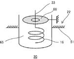
- the radiation antenna 16 is provided on the ceiling surface 51 of the combustion chamber 20.
- the radiation antenna 16 is provided in a region between the two intake side openings 25a. As shown in FIG. 1, the radiation antenna 16 protrudes from the ceiling surface 51 of the combustion chamber 20.
- the radiation antenna 16 is formed in a spiral shape and embedded in the insulator 65.
- the length of the radiation antenna 16 is a quarter of the wavelength of the microwave in the radiation antenna 16.
- the radiation antenna 16 is electrically connected to the output terminal of the electromagnetic wave switch 32 through a microwave transmission line 33 embedded in the cylinder head 22.
- the electromagnetic wave radiation device 13 is configured to be able to adjust the frequency of the microwave radiated from the radiation antenna 16 to the combustion chamber 20.
- the electromagnetic wave generator 31 is configured to be able to adjust the oscillation frequency of the microwave.
- the oscillation frequency can be continuously adjusted.
- X (Hz) is a value of several to several tens (Hz), for example, 10 (Hz).
- the electromagnetic wave emission device 13 may include a plurality of electromagnetic wave generation devices 31 having different oscillation frequencies, and the frequency of the microwave radiated to the combustion chamber 20 may be adjusted by switching the electromagnetic wave generation device 31 to be used. -Control device operation-
- the operation of the control device 35 will be described.
- the control device 35 performs a first operation for instructing the ignition device 12 to ignite the air-fuel mixture in one combustion cycle for each combustion chamber 20, and a microwave is applied to the electromagnetic wave emission device 13 after the ignition of the air-fuel mixture.
- a second operation for instructing radiation is performed.
- control device 35 performs the first operation at the ignition timing at which the piston 23 is positioned before the compression top dead center.
- the control device 35 outputs an ignition signal as the first operation.
- spark discharge occurs in the discharge gap of the spark plug 40 as described above.
- the air-fuel mixture is ignited by spark discharge.
- the flame spreads from the ignition position of the air-fuel mixture at the center of the combustion chamber 20 toward the wall surface of the cylinder 24.
- the control device 35 performs the second operation after the air-fuel mixture has ignited, for example, at the start timing of the second half period of flame propagation.
- the control device 35 outputs an electromagnetic wave drive signal as the second operation.
- the electromagnetic wave radiation device 13 When receiving the electromagnetic wave drive signal, the electromagnetic wave radiation device 13 repeatedly radiates the microwave pulse from the radiation antenna 16 as described above. The microwave pulse is emitted repeatedly over the second half of the flame propagation.
- control device 35 controls the frequency of the microwave radiated to the combustion chamber 20 by the electromagnetic wave radiation device 13 in consideration of the resonance frequency of the combustion chamber 20 according to the operating state of the internal combustion engine body 11. Means.
- the control device 35 controls the oscillation frequency of the electromagnetic wave generator 31 in order to control the frequency of the microwave radiated from the electromagnetic wave emitter 13 to the combustion chamber 20.
- the oscillation frequency target value (output value) preset between the first set value f1 and the second set value f2 is input.
- the control map is created in consideration of the resonance frequency of the combustion chamber 20 according to the operating state of the internal combustion engine body 11. For example, in the control map, the target value of the oscillation frequency is set to a larger value as it approaches the high load / high rotation region from the low load / low rotation region.
- the control device 35 reads the target value of the oscillation frequency from the control map, and sets the oscillation frequency of the electromagnetic wave generator 31 to the target value.
- the combustion chamber 20 is radiated with a microwave having a frequency considering the resonance frequency of the combustion chamber 20. For this reason, since the microwaves appropriately resonate in the combustion chamber 20 during the propagation of the flame, the propagation speed of the flame is effectively improved.
- microwave plasma When the microwave energy is large, microwave plasma is generated in the strong electric field region of the combustion chamber 20. Active species (for example, OH radicals) are generated in the generation region of the microwave plasma. The propagation speed of the flame passing through the strong electric field region is increased by the active species.
- the microwave frequency radiated to the combustion chamber 20 is controlled in consideration of the resonance frequency of the combustion chamber 20 so that the microwave appropriately resonates in the combustion chamber 20 during the propagation of the flame. I have to. Therefore, the propagation speed of the flame can be improved by effectively using the microwave energy in the combustion chamber 20.
- the control device 35 controls the frequency of the microwave radiated to the combustion chamber 20 by the electromagnetic wave emission device 13 in consideration of the resonance frequency of the combustion chamber 20 according to the propagation state of the flame. It constitutes a control means.
- the control device 35 controls the oscillation frequency of the electromagnetic wave generator 31 in order to control the frequency of the microwave radiated from the electromagnetic wave emitter 13 to the combustion chamber 20.
- the control device 35 determines the microwave from the time difference between the execution timing of the first operation (ignition timing of the air-fuel mixture by the ignition device 12) and the start timing of the second operation (radiation start timing of microwaves by the electromagnetic wave emission device 13). It is estimated how much the flame spreads at the time of starting the emission of, and the target value of the oscillation frequency is determined based on the estimation result. For example, as the time difference between the execution timing of the first operation and the start timing of the second operation is larger, the control device 35 estimates that the flame spreads more widely at the time of starting the microwave emission, and the oscillation frequency Set the target value to a large value.
- the control device 35 sets the oscillation frequency of the electromagnetic wave generator 31 to the target value.
- the combustion chamber 20 is radiated with a microwave having a frequency considering the resonance frequency of the combustion chamber 20. For this reason, since the microwaves appropriately resonate in the combustion chamber 20 during the propagation of the flame, the propagation speed of the flame is effectively improved.
- the ring-shaped receiving antenna 52 that resonates with the microwave radiated from the radiation antenna 16 to the combustion chamber 20 is provided on the partition member that partitions the combustion chamber 20.
- two receiving antennas 52a and 52b are provided in a portion of the partition member that partitions a region near the outer periphery of the combustion chamber 20.
- the receiving antennas 52 a and 52 b are provided in a region near the outer periphery of the top of the piston 23.
- Each of the receiving antennas 52a and 52b is provided on an insulating layer 56 laminated on the top surface of the piston 23.
- the present invention is useful for an internal combustion engine that uses electromagnetic waves to promote combustion of an air-fuel mixture in a combustion chamber.
Abstract
Description
-内燃機関本体- The present embodiment is an
-Internal combustion engine body-
-点火装置- An
-Ignition device-
-電磁波放射装置- The
-Electromagnetic radiation device-
-制御装置の動作- The electromagnetic
-Control device operation-
-実施形態の効果- When the microwave energy is large, microwave plasma is generated in the strong electric field region of the
-Effect of the embodiment-
-実施形態の変形例1- In the present embodiment, the microwave frequency radiated to the
—Modification 1 of Embodiment—
-実施形態の変形例2- When setting the target value of the oscillation frequency, the
-Modification Example 2-
11 内燃機関本体
12 点火装置
13 電磁波放射装置
16 放射アンテナ
20 燃焼室
35 制御装置(制御手段) DESCRIPTION OF
Claims (2)
- 燃焼室が形成された内燃機関本体と、
前記燃焼室において混合気に点火する点火装置とを備え、
前記点火装置により混合気に点火して該混合気を燃焼させる燃焼サイクルが繰り返し行われる内燃機関であって、
混合気が着火された後の火炎の伝播中に前記燃焼室へ電磁波を放射する電磁波放射装置と、
前記内燃機関本体の運転状況に応じて前記燃焼室の共振周波数を考慮して、前記電磁波放射装置が前記燃焼室へ放射する電磁波の周波数を制御する制御手段とを備えている
ことを特徴とする内燃機関。 An internal combustion engine body in which a combustion chamber is formed;
An ignition device for igniting the air-fuel mixture in the combustion chamber,
An internal combustion engine in which a combustion cycle for igniting an air-fuel mixture by the ignition device and combusting the air-fuel mixture is repeatedly performed,
An electromagnetic wave radiation device that radiates electromagnetic waves to the combustion chamber during propagation of a flame after the air-fuel mixture is ignited;
Control means for controlling the frequency of the electromagnetic wave radiated to the combustion chamber by the electromagnetic wave radiation device in consideration of the resonance frequency of the combustion chamber in accordance with the operating state of the internal combustion engine main body. Internal combustion engine. - 燃焼室が形成された内燃機関本体と、
前記燃焼室において混合気に点火する点火装置とを備え、
前記点火装置により混合気に点火して該混合気を燃焼させる燃焼サイクルが繰り返し行われる内燃機関であって、
混合気が着火された後の火炎の伝播中に前記燃焼室へ電磁波を放射する電磁波放射装置と、
前記火炎の伝播状況に応じて前記燃焼室の共振周波数を考慮して、前記電磁波放射装置が前記燃焼室へ放射する電磁波の周波数を制御する制御手段とを備えている
ことを特徴とする内燃機関。 An internal combustion engine body in which a combustion chamber is formed;
An ignition device for igniting the air-fuel mixture in the combustion chamber,
An internal combustion engine in which a combustion cycle for igniting an air-fuel mixture by the ignition device and combusting the air-fuel mixture is repeatedly performed,
An electromagnetic wave radiation device that radiates electromagnetic waves to the combustion chamber during propagation of a flame after the air-fuel mixture is ignited;
An internal combustion engine comprising control means for controlling the frequency of the electromagnetic wave radiated to the combustion chamber by the electromagnetic wave radiation device in consideration of the resonance frequency of the combustion chamber in accordance with the propagation state of the flame .
Priority Applications (3)
| Application Number | Priority Date | Filing Date | Title |
|---|---|---|---|
| JP2013524713A JP6086443B2 (en) | 2011-07-16 | 2012-07-13 | Internal combustion engine |
| EP12815094.3A EP2733348B1 (en) | 2011-07-16 | 2012-07-13 | Internal combustion engine |
| US14/156,068 US10151291B2 (en) | 2011-07-16 | 2014-01-15 | Internal combustion engine |
Applications Claiming Priority (4)
| Application Number | Priority Date | Filing Date | Title |
|---|---|---|---|
| JP2011-157285 | 2011-07-16 | ||
| JP2011157285 | 2011-07-16 | ||
| JP2011175394 | 2011-08-10 | ||
| JP2011-175394 | 2011-08-10 |
Related Child Applications (1)
| Application Number | Title | Priority Date | Filing Date |
|---|---|---|---|
| US14/156,068 Continuation US10151291B2 (en) | 2011-07-16 | 2014-01-15 | Internal combustion engine |
Publications (1)
| Publication Number | Publication Date |
|---|---|
| WO2013011967A1 true WO2013011967A1 (en) | 2013-01-24 |
Family
ID=47558144
Family Applications (1)
| Application Number | Title | Priority Date | Filing Date |
|---|---|---|---|
| PCT/JP2012/068010 WO2013011967A1 (en) | 2011-07-16 | 2012-07-13 | Internal combustion engine |
Country Status (4)
| Country | Link |
|---|---|
| US (1) | US10151291B2 (en) |
| EP (1) | EP2733348B1 (en) |
| JP (1) | JP6086443B2 (en) |
| WO (1) | WO2013011967A1 (en) |
Cited By (1)
| Publication number | Priority date | Publication date | Assignee | Title |
|---|---|---|---|---|
| JP2020041508A (en) * | 2018-09-12 | 2020-03-19 | 株式会社Soken | Ignition device |
Families Citing this family (2)
| Publication number | Priority date | Publication date | Assignee | Title |
|---|---|---|---|---|
| WO2013011966A1 (en) * | 2011-07-16 | 2013-01-24 | イマジニアリング株式会社 | Internal combustion engine |
| WO2013011965A1 (en) * | 2011-07-16 | 2013-01-24 | イマジニアリング株式会社 | Internal combustion engine, and plasma generating device |
Citations (4)
| Publication number | Priority date | Publication date | Assignee | Title |
|---|---|---|---|---|
| JP2001501699A (en) * | 1996-09-30 | 2001-02-06 | ビビッチ、マシュー、マーク | Ignition by electromagnetic radiation |
| JP2007113570A (en) | 2005-09-20 | 2007-05-10 | Imagineering Kk | Ignition device, internal combustion engine, ignition plug, plasma device, exhaust gas decomposition device, ozone generation/sterilization/infection device, and deodorizing device |
| JP2009103038A (en) * | 2007-10-23 | 2009-05-14 | Nissan Motor Co Ltd | Engine ignition device |
| JP2011132900A (en) * | 2009-12-25 | 2011-07-07 | Mitsubishi Electric Corp | Ignition device |
Family Cites Families (11)
| Publication number | Priority date | Publication date | Assignee | Title |
|---|---|---|---|---|
| US3589177A (en) * | 1968-10-02 | 1971-06-29 | Merlo Angelo L | Combustion microwave diagnostic system |
| US4138980A (en) * | 1974-08-12 | 1979-02-13 | Ward Michael A V | System for improving combustion in an internal combustion engine |
| GB1544461A (en) * | 1975-10-14 | 1979-04-19 | Ward M | Internal combustion engines |
| US4297983A (en) * | 1978-12-11 | 1981-11-03 | Ward Michael A V | Spherical reentrant chamber |
| US4403504A (en) * | 1981-08-13 | 1983-09-13 | General Motors Corporation | Engine testing microwave transmission device |
| JPS58204978A (en) * | 1982-05-25 | 1983-11-29 | Toyota Central Res & Dev Lab Inc | Combustion time detecting device |
| US4561406A (en) * | 1984-05-25 | 1985-12-31 | Combustion Electromagnetics, Inc. | Winged reentrant electromagnetic combustion chamber |
| FR2895170B1 (en) * | 2005-12-15 | 2008-03-07 | Renault Sas | OPTIMIZING THE EXCITATION FREQUENCY OF A RESONATOR |
| WO2008035448A1 (en) * | 2006-09-20 | 2008-03-27 | Imagineering, Inc. | Ignition device, internal combustion engine, ignition plug, plasma apparatus, exhaust gas decomposition apparatus, ozone generation/sterilization/disinfection apparatus, and deodorization apparatus |
| JP2010001827A (en) * | 2008-06-20 | 2010-01-07 | Mitsubishi Electric Corp | Ignition device for internal combustion engine |
| US9359934B2 (en) * | 2009-11-30 | 2016-06-07 | Imagineering, Inc. | Internal combustion engine control device |
-
2012
- 2012-07-13 WO PCT/JP2012/068010 patent/WO2013011967A1/en active Application Filing
- 2012-07-13 JP JP2013524713A patent/JP6086443B2/en not_active Expired - Fee Related
- 2012-07-13 EP EP12815094.3A patent/EP2733348B1/en not_active Not-in-force
-
2014
- 2014-01-15 US US14/156,068 patent/US10151291B2/en not_active Expired - Fee Related
Patent Citations (4)
| Publication number | Priority date | Publication date | Assignee | Title |
|---|---|---|---|---|
| JP2001501699A (en) * | 1996-09-30 | 2001-02-06 | ビビッチ、マシュー、マーク | Ignition by electromagnetic radiation |
| JP2007113570A (en) | 2005-09-20 | 2007-05-10 | Imagineering Kk | Ignition device, internal combustion engine, ignition plug, plasma device, exhaust gas decomposition device, ozone generation/sterilization/infection device, and deodorizing device |
| JP2009103038A (en) * | 2007-10-23 | 2009-05-14 | Nissan Motor Co Ltd | Engine ignition device |
| JP2011132900A (en) * | 2009-12-25 | 2011-07-07 | Mitsubishi Electric Corp | Ignition device |
Non-Patent Citations (1)
| Title |
|---|
| See also references of EP2733348A4 |
Cited By (2)
| Publication number | Priority date | Publication date | Assignee | Title |
|---|---|---|---|---|
| JP2020041508A (en) * | 2018-09-12 | 2020-03-19 | 株式会社Soken | Ignition device |
| JP7186041B2 (en) | 2018-09-12 | 2022-12-08 | 株式会社Soken | ignition device |
Also Published As
| Publication number | Publication date |
|---|---|
| US10151291B2 (en) | 2018-12-11 |
| JP6086443B2 (en) | 2017-03-01 |
| US20140196679A1 (en) | 2014-07-17 |
| EP2733348A1 (en) | 2014-05-21 |
| EP2733348A4 (en) | 2015-02-25 |
| JPWO2013011967A1 (en) | 2015-02-23 |
| EP2733348B1 (en) | 2017-03-01 |
Similar Documents
| Publication | Publication Date | Title |
|---|---|---|
| WO2012124671A2 (en) | Internal combustion engine | |
| JP6040362B2 (en) | Internal combustion engine | |
| WO2013191142A1 (en) | Antenna structure and internal combustion engine | |
| JP6082880B2 (en) | High frequency radiation plug | |
| JP6023956B2 (en) | Internal combustion engine | |
| JP6064138B2 (en) | Internal combustion engine and plasma generator | |
| JP6014864B2 (en) | Spark ignition internal combustion engine | |
| JP6298961B2 (en) | Electromagnetic radiation device | |
| WO2013021852A1 (en) | Internal combustion engine | |
| JP6191030B2 (en) | Plasma generator and internal combustion engine | |
| JP6086443B2 (en) | Internal combustion engine | |
| JP6023966B2 (en) | Internal combustion engine | |
| JP6145760B2 (en) | High frequency radiation plug and internal combustion engine | |
| JPWO2013035881A1 (en) | Antenna structure, high-frequency radiation plug, and internal combustion engine |
Legal Events
| Date | Code | Title | Description |
|---|---|---|---|
| 121 | Ep: the epo has been informed by wipo that ep was designated in this application |
Ref document number: 12815094 Country of ref document: EP Kind code of ref document: A1 |
|
| ENP | Entry into the national phase |
Ref document number: 2013524713 Country of ref document: JP Kind code of ref document: A |
|
| NENP | Non-entry into the national phase |
Ref country code: DE |
|
| REEP | Request for entry into the european phase |
Ref document number: 2012815094 Country of ref document: EP |
|
| WWE | Wipo information: entry into national phase |
Ref document number: 2012815094 Country of ref document: EP |