WO2012176754A1 - 画像再構成装置 - Google Patents
画像再構成装置 Download PDFInfo
- Publication number
- WO2012176754A1 WO2012176754A1 PCT/JP2012/065592 JP2012065592W WO2012176754A1 WO 2012176754 A1 WO2012176754 A1 WO 2012176754A1 JP 2012065592 W JP2012065592 W JP 2012065592W WO 2012176754 A1 WO2012176754 A1 WO 2012176754A1
- Authority
- WO
- WIPO (PCT)
- Prior art keywords
- image
- observation target
- projection
- image reconstruction
- arithmetic expression
- Prior art date
- Legal status (The legal status is an assumption and is not a legal conclusion. Google has not performed a legal analysis and makes no representation as to the accuracy of the status listed.)
- Ceased
Links
Images


Classifications
-
- G—PHYSICS
- G06—COMPUTING OR CALCULATING; COUNTING
- G06T—IMAGE DATA PROCESSING OR GENERATION, IN GENERAL
- G06T12/00—Tomographic reconstruction from projections
- G06T12/20—Inverse problem, i.e. transformations from projection space into object space
-
- A—HUMAN NECESSITIES
- A61—MEDICAL OR VETERINARY SCIENCE; HYGIENE
- A61B—DIAGNOSIS; SURGERY; IDENTIFICATION
- A61B6/00—Apparatus or devices for radiation diagnosis; Apparatus or devices for radiation diagnosis combined with radiation therapy equipment
- A61B6/52—Devices using data or image processing specially adapted for radiation diagnosis
- A61B6/5205—Devices using data or image processing specially adapted for radiation diagnosis involving processing of raw data to produce diagnostic data
Definitions
- the present invention relates to an image reconstruction device, and more particularly to improvement of image quality.
- CT Computer Tomography
- the CT technique is classified into an analytical method and a successive approximation method according to a method for reconstructing the image, and the successive approximation method is further classified into an algebraic method and a statistical method.
- FIG. 7 is an explanatory diagram showing an example of an image reconstruction method in the conventional CT technique.
- the shooting angle ⁇ is discrete, the sampling interval between the projected images increases (A) and the image becomes blurred (B) as it goes outward from the center of the observation target.
- a method has been proposed in which the filter f is used and first applied to the projection image y and then f * y and inverse transformation Wt are performed.
- a filter f there is, for example, a so-called Ramachandran-Lakshminarayanan filter. Since this method is widely known, detailed description thereof is omitted, but the image obtained after the inverse transformation is relatively close to the original image.
- Patent Document 1 discloses a technique for performing super-resolution processing on a CT image.
- inverse Radon transform performs an integration operation over the entire reconstructed image
- a fatal artifact may occur if a part of the information is missing.
- an electron microscope CT or the like there is a limit on the angle at which an image can be captured due to structural limitations of the imaging target, and information cannot be captured in the range of the angle related to the limitation.
- a radial artifact is generated.
- the applicability is poor because the filter f must be designed according to the imaging mode of the projected image.
- the present invention has been made in view of the above circumstances, and an object of the present invention is to provide an image reconstruction device that can easily cope with various imaging modes of projected images and has improved applicability.
- Another object of the present invention is to provide an image reconstruction device that can improve image quality, such as suppressing artifacts caused by various factors.
- An invention for solving the problems of the above conventional example is an image reconstruction device, which accepts image data relating to a plurality of projection images obtained from different directions with respect to the observation target and transmitted through the observation target. And a projection function based on a distribution function indicating that there is a predetermined correlation between pixels of the observation target image and a condition relating to a process until a projection image is obtained based on the observation target.
- FIG. 1 is a configuration block diagram illustrating an example of an image reconstruction device according to an embodiment of the present invention. It is a functional block diagram concerning an example of an image reconstruction device concerning an embodiment of the invention. It is explanatory drawing showing an example of the process of obtaining a projection image from a cross-sectional image. It is a flowchart figure showing the process example of the image reconstruction apparatus which concerns on embodiment of this invention. It is explanatory drawing showing the example of the image respectively reconfigure
- the image reconstruction device 1 includes a control unit 11, a storage unit 12, an input unit 13, and an output unit 14.
- control unit 11 is a program control device such as a CPU (Central Processing Unit), and operates according to a program stored in the storage unit 12.
- the control unit 11 accepts image data relating to a plurality of projection images obtained from different directions with respect to the observation target and transmitted through the observation target, and between the pixels of the image of the observation target.
- Bayesian estimation a process for estimating the cross-sectional image of the observation target from the arithmetic expression representing the probabilistic model and the received image data is executed. Details of the processing of the control unit 11 will be described later.
- the storage unit 12 is a memory device, a disk device, or the like, and holds a program executed by the control unit 11. This program may be provided by being stored in a computer-readable recording medium such as a DVD-ROM and copied to the storage unit 12.
- the storage unit 12 also operates as a work memory for the control unit 11.
- the input unit 13 includes, for example, a serial or parallel input interface, receives image data obtained by imaging with a CT apparatus, and outputs the image data to the control unit 11.
- the output unit 14 is a display, a printer, or the like, and displays and outputs image data in accordance with an instruction input from the control unit 11.
- the plurality of projection images to be processed by the image reconstruction device 1 according to the present embodiment are transmitted through the observation target or scattered by the observation target from different directions with respect to the observation target. Is obtained by imaging with a detector in which a plurality of detection elements (channels) are arrayed.
- a plurality of observation elements on a virtual plane that cuts the observation object in a circle It is a projection image by the general CT apparatus which irradiates X-ray from the angle direction of this. That is, a plurality of projection images obtained by projecting a cross-sectional image when the observation target is cut along the plane from a plurality of angles are set as processing targets.
- the control unit 11 of the image reconstruction device 1 functionally includes an image data reception unit 21, a luminance vector extraction unit 22, a transformation matrix generation unit 23, a Bayes, as illustrated in FIG.
- the estimation unit 24 and the reconstruction unit 25 are included.
- the image data receiving unit 21 receives input (for example, K pieces) of image data of a plurality of projection images from the input unit 13 and accumulates and stores them in the storage unit 12.
- the image data of the projected image includes data representing a plurality of pixel values (output values for each detection element).
- the pixel value data includes, for example, a luminance value.
- the transformation matrix generation unit 23 generates an arithmetic expression related to a prior distribution used for Bayes estimation. That is, the luminance vector representing the original image (cross-sectional image) is x, the projection transformation matrix representing the Radon transform for obtaining the projection image is W (k), and the error caused by the conditions at the time of imaging is ⁇ (k), It can be expressed as. That is,
- ⁇ is accuracy (reciprocal of variance)
- I is a unit matrix of the same dimension as W (k)
- M is a dimension of y (k)
- a, b) is an average vector a
- a distribution function with a variance matrix of b is selected in advance by the user from widely known distribution functions such as a Gaussian distribution and a Poisson distribution.
- the transformation matrix generation unit 23 uses the projection transformation matrix W (k) as a matrix representing at least one affine transformation (matrix representing translation, rotation, reduction / enlargement, etc.) or a product (in the case of a plurality thereof), for example, It is determined as follows. That is, as a condition related to the process until the projection image is obtained from the observation target, the angle when the kth projection image is obtained is ⁇ k , the size of the projection image (dimension of the luminance vector) is M, and the original of the observation target The size of the image (dimension of the luminance vector) is N, and the width of the disk image, that is, the point spread function indicating the size of the disk image projected on the projected image by the imaging.
- W (k) a matrix representing at least one affine transformation (matrix representing translation, rotation, reduction / enlargement, etc.) or a product (in the case of a plurality thereof), for example, It is determined as follows. That is, as a condition related to the process until
- the pixel value uj (k) on the projected image can be obtained by converting the element vj of the pixel vector as follows.
- the transformation matrix generation unit 23 generates an arithmetic expression p (x) representing a prior distribution (that is, an evaluation function of the cross-sectional image itself that is the original image) based on the constraint condition regarding the image to be observed. Specifically, this distribution is determined as follows. That is, in the image to be observed (image to be reconstructed), there is a correlation between pixels, and it is assumed that the difference in luminance does not exceed a predetermined threshold value between adjacent pixels. As such p (x), for example, there is a Gaussian distribution (the following equation).
- the fixed matrix Zx representing the variance is Where vi is the pixel value at the position i (in this case, the luminance value), r is the distance between the pixels, and A is a coefficient determined empirically.
- the transformation matrix generation unit 23 outputs the generated equations (2) and (4) relating to p (D
- the Bayesian estimation unit 24 calculates the posterior distribution p (x
- D) giving the probability that the image is x is It becomes.
- ⁇ is an average vector.
- the Bayesian estimation unit 24 calculates the average vector ⁇ included in the equation (7). This mean vector ⁇ is It is. Where ⁇ is the variance matrix, It is expressed.
- the reconstruction unit 25 calculates and outputs the average vector ⁇ as a vector of image brightness.
- the image reconstruction device 1 of the present embodiment performs the processing shown in FIG. 4 and accepts a plurality of one-dimensional images for n pixels. Then, a plurality of n-dimensional vectors y1, y2,..., Yk in which the luminance values of the respective pixels of each one-dimensional image are arranged are obtained (S1).
- the luminance value is used, but in the case of color, a vector of values in a predetermined color space (for example, R, G, and B values) may be used.
- the image reconstruction apparatus 1 sets the angle when obtaining the kth projection image as ⁇ k and the size of the projection image (dimension of the luminance vector) as conditions relating to the process until the projection image is obtained from the observation target.
- M the size of the original image to be observed (dimension of the luminance vector) is N
- the width of the disk image that represents the size of the disk image projected on the projected image by imaging that is, the point spread
- the matrix R ( ⁇ k ) representing the rotation of ⁇ k and the matrix representing the translation by ⁇ are T ( ⁇ ).
- a matrix F (k) to be obtained is obtained (S2).
- the image reconstruction device 1 converts the pixel vector element vj by this F (k) to obtain a pixel value uj (k) on the projection image, and uses this uj (k) to determine the element.
- a transformation matrix W (k) is obtained (S3).
- x) is obtained as in equation (2) (S4).
- the image reconstruction device 1 generates an arithmetic expression p (x) representing a prior distribution based on the constraint condition regarding the image to be observed (expression (4)) (S5), and the generated p (D
- the average vector ⁇ is a vector obtained by arranging the luminance values (pixel values) of pixels to be included in the reconstructed image in a predetermined order, the value of each pixel of the original image according to the order. Is determined from the value of the corresponding component in the average vector ⁇ (for example, the value itself), thereby obtaining the original image.
- the process of obtaining a projection image from a cross-sectional image of the original observation object is described as it is as a probabilistic model for generating an observation image.
- the maximum likelihood cross-sectional image (observation target image) is directly estimated from the image.
- various types such as a helical scan, a cone beam, a multi-CT, a phase CT, and a three-dimensional CT are available.
- a reconstructed image can be obtained for a projected image obtained by the above projection process.
- the image reconstruction apparatus 1 calculates a projection transformation matrix W (k) representing Radon transformation as an arithmetic expression representing a condition related to a process until a projection image is obtained from an observation target.
- W (k) representing Radon transformation
- the following matrix F (k) may be used. That is, the angle when the kth projection image is obtained is ⁇ k , the size of the projection image (dimension of the luminance vector) is M, the size of the original image to be observed (dimension of the luminance vector) is N, and the point by imaging
- a matrix R representing the rotation of ⁇ k using the width of the disk image, that is, the size ⁇ of the point spread function, representing what size disk image is projected in the projected image.
- T ( ⁇ ) represents a matrix representing translation by ⁇ , and includes translation T (S k ) based on a shift vector S k representing a positional deviation when the kth projection image is obtained. , It is good.
- This matrix F (k) is based on the assumption that a positional deviation of S k has occurred when the k-th projected image is captured. In practice, however, the amount S k of this positional deviation is a disturbance. It is difficult to measure. Also, ⁇ k and ⁇ may be different from predetermined values during actual shooting due to disturbance. That is, it can be said that S k , ⁇ k , and ⁇ are unknown parameters.
- the image reconstruction device 1 estimates these unknown parameters using a so-called EM algorithm (expected value maximization method) or a direct estimation method.
- EM algorithm expected value maximization method
- the set of unknown parameters far.
- one logarithmic value of the arithmetic expression that represents the probabilistic model to be finally obtained This expectation is maximized.
- S k and ⁇ may be set to 0, and ⁇ k may be set to an angle representing the X-ray track direction when the k-th projection image is obtained, that is, a set angle at the time of photographing, or may be determined at random. Good.
- the image reconstruction device 1 is a term related to ⁇ t in the expression (11) in the step of evaluating the expected value (E step). Is calculated. Hereinafter, it is considered to maximize the expression (12).
- ⁇ that maximizes the equation (12) is obtained, and this is set as the next set of unknown parameters ⁇ t + 1 . That is, And
- the image reconstruction apparatus 1 repeatedly executes the E step and the M step alternately until this ⁇ converges, that is, until the magnitude of the vector ⁇ t + 1 ⁇ t falls below a predetermined threshold value. . If ⁇ after convergence is obtained, the value of the unknown parameter included in ⁇ is used to obtain the matrix F (k), further the projection transformation matrix W (k), and the likelihood function p (D
- the image reconstruction device may directly obtain ⁇ that maximizes the marginal likelihood. That is, the marginal likelihood Find ⁇ to maximize this It is good as well.
- a region where data is lost may occur in the projection image due to the high X-ray absorption rate of the metal. This may be the case, for example, when an image of the oral cavity containing a metal crown (a covering used in dentistry) is used, but the conventional method cannot avoid the artifacts (so-called metal artifacts) caused by the missing area. .
- an Ising model or the like that expresses an edge of an estimated image including the missing region is used as the prior distribution p (x) based on the constraint condition regarding the image to be observed. To reduce this metal artifact.
- the matrix F (k) when calculating the projection transformation matrix W (k) there are characteristics (sensitivity, etc.) of the image sensor used for capturing the projection image, and the observation target
- various information such as information indicating the property of the substance such as the X-ray absorption rate of the object to be included in the estimated cross section can be used.
- the matrix F (k) for obtaining the projection transformation matrix W (k) includes parameters related to the resolution of the image obtained, so-called super-resolution processing for reconstructing an image having a higher resolution than the projection image is performed. It may be done.
- each condition is determined when generating a matrix F (k) that represents a condition related to a process from the observation target until a projection image is obtained. May be generated as a product of a matrix representing
- a matrix L that approximates the nonlinear scattering linearly is created.
- the matrix F (k) is obtained by the product of the matrix including the matrix L in the same manner as shown in the equation (3) or (10).
- a matrix F (k) is obtained by the product of a plurality of matrices including a matrix representing that effect.
- Electromagnetic waves and particle beams detected by these detection elements are not generally single wavelengths but include electromagnetic waves and substance waves (de Broglie waves) of various wavelengths from components having relatively long wavelengths to components having relatively short wavelengths.
- This beam hardening is a phenomenon in which, while these X-rays or the like pass through the object to be imaged, a component having a relatively long wavelength is absorbed more, and a component having a short wavelength increases as a result of transmission, resulting in higher energy. . If this phenomenon occurs when CT is used for medical purposes, it may appear that there is a low absorption region that does not actually exist in the body. Therefore, a matrix representing a change in CT data due to beam hardening (attenuation of energy such as X-ray) is included in the matrix F (k) as shown in the expression (3) or (10). include.
- the matrix A includes the matrix F (k) as an unknown parameter that includes the attenuation amount of the wavelength-dependent electromagnetic wave or particle beam energy in each part of the projection target that occurs during the imaging process of the k-th projection image. It may be expressed by a product of (a ⁇ 1 , a ⁇ 2 ). And other matrices M (r), T (S k ), and the like representing conversion in the imaging process.
- a ⁇ n may be determined by selecting a plurality of predetermined wavelengths (for example, by selecting at least one representative wavelength from each frequency band considered to have different absorption rates) ⁇ 1 , ⁇ 2 ,...
- the matrix F (k) represented by the product of a plurality of matrices including this matrix represents the pixel value that is the output value for each detection element with a multidimensional absorption coefficient.
- the absorptance for each wavelength band is estimated, and artifacts and the like generated due to the difference in the absorptance for each wavelength band are reduced.
- the matrix F (k) representing various conditions related to the process until the projection image is obtained from the observation target, it is possible to reproduce the image reflecting various imaging modes and the characteristics of the imaging target. Configuration may be performed.
- the image reconstruction device 1 is realized by using a computer adopting Intel® Xeno® 2.66 GHz (4 cores) as a CPU as the control unit 11 is shown below.
- FIG. 5 shows the 32 ⁇ 8, 32 ⁇ 16, 32 ⁇ 32, and 32 ⁇ 64 pixel sinograms (R) obtained for the original 64 ⁇ 64 pixel two-dimensional image (A).
- Reconstructed image (B) obtained by performing transformation, reconstructed image (C) using a filter, reconstructed image (D) by the successive approximation method, reconstructed image obtained by the image reconstruction device 1 of this embodiment (E) is contrasted.
- each reconstructed image (B, C, D, E) represents a reconstructed image obtained from a sinogram of 32 ⁇ 8, 32 ⁇ 16, 32 ⁇ 32, and 32 ⁇ 64 pixels in order from the top.
- reproducibility can be greatly improved as compared with an example using a filter and an example using successive approximation.
Landscapes
- Physics & Mathematics (AREA)
- General Physics & Mathematics (AREA)
- Engineering & Computer Science (AREA)
- Theoretical Computer Science (AREA)
- Apparatus For Radiation Diagnosis (AREA)
Abstract
【課題】種々の投影像の撮像態様に容易に対応でき、応用性を向上した画像再構成装置及びプログラムを提供する。 【解決手段】観測対象に対して互いに異なる方向から得た、観測対象を透過した複数の投影像に係る画像データを受け入れ、観測対象の像の画素間に、予め定めた相関があることを表す分布関数と、当該観測対象に基づいて投影像が得られるまでの過程に係る条件とに基づいて、投影像を生成する確率的モデルを表す演算式を生成し、ベイズ推定を用いて、確率的モデルを表す演算式と、画像データとから観測対象の断面像を推定する画像再構成装置である。
Description
本発明は、画像再構成装置に係り、特に画質の向上に関する。
観測対象のX線撮像画像を、観測対象の外部から様々な角度θで撮影し、撮影によって得られた複数の画像を用いて、観測対象の内部の画像を再構成する技術が知られている。この技術は、CT(Computed Tomography)と呼ばれ、医療や製品製造などの種々の場面で利用されている。
CT技術は、その画像を再構成する方法によって、解析的方法と、逐次近似法とに分類され、また逐次近似法はさらに、代数的方法と統計的方法とに分類される。
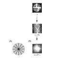
図7は、従来のCT技術における画像の再構成法の例を表す説明図である。観測対象xをCTにより撮影した投影像yは、元の像xのラドン変換(Radon変換)Wの結果として得られる。すなわちy=Wx。そこで理論的には、この投影像yを逆ラドン変換することにより(x=Wty)、元の像が得られることとなる。しかしながら、現実には撮影角度θが離散的であるため、観測対象の中心部から外側へ向かうに連れて、投影像間のサンプリング間隔が広がり(A)、像がぼけてしまう(B)。
そこでフィルタfを用い、まず投影像yに適用した上でf*y、逆変換Wtを行う方法が提案されている。このようなフィルタfとしては、例えば、Ramachandran-Lakshminarayananフィルタと呼ばれるものがある。この方法は広く知られているので、詳しい説明を省略するが、これにより得られた逆変換後の像は比較的元の像に近いものとなる。
特許文献1にはCT画像に対して超解像処理を行う技術が開示されている。
しかしながら、上記従来の方法では、検出器に由来するノイズや、撮像や再構成時の回転軸ずれ、回転量のゆらぎ等の影響が考慮されず、再構成した像に様々なアーチファクト(artifact:実際には存在しない像)が発生することが知られている。
また逆ラドン変換には、再構成像全体に亘る積分操作が行われるので、情報の一部が欠損している場合、致命的なアーチファクトを発生させる場合がある。例えば、電子顕微鏡CT等では撮像対象の構造的な制約から、撮影可能な角度に制限があり、制限に係る角度の範囲では撮像ができないので、情報の欠損が生じる。また観測対象の一部に、他の部分とは放射線吸収率が大きく異なる部分があると、放射状のアーチファクトが生じる。
一方、フィルタfを用いずに、予め定めた更新ベクトルq_kと、重みαkとを用いて、元の像の推定像xkを、逐次的にxk=xk-1+αkqkとして近似していく方法もある。この方法によれば、フィルタを用いる方法に比べ、情報の欠損に対してはアーチファクトの発生を抑制できるものの、他の要因に基づくアーチファクトを抑制できない。
さらに、これらフィルタfを用いる方法や、逐次的に近似する方法では、投影像の撮像態様に応じてフィルタfを設計しなければならないなど、応用性に乏しい。
本発明は上記実情に鑑みて為されたもので、種々の投影像の撮像態様に容易に対応でき、応用性を向上した画像再構成装置を提供することを、その目的の一つとする。
また本発明の他の目的の一つは、種々の要因で発生するアーチファクトを抑制するなど、画質を向上できる画像再構成装置を提供することである。
上記従来例の問題点を解決するための発明は、画像再構成装置であって、観測対象に対して互いに異なる方向から得た、観測対象を透過した複数の投影像に係る画像データを受け入れる手段と、前記観測対象の像の画素間に、予め定めた相関があることを表す分布関数と、当該観測対象に基づいて投影像が得られるまでの過程に係る条件とに基づいて、前記投影像を生成する確率的モデルを表す演算式を生成する手段と、ベイズ推定を用いて、前記確率的モデルを表す演算式と、前記画像データとから観測対象の断面像を推定する手段と、を含むこととしたものである。
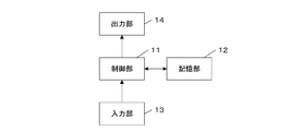
本発明の実施の形態について図面を参照しながら説明する。本発明の実施の形態に係る画像再構成装置1は、図1に例示するように、制御部11と、記憶部12と、入力部13と、出力部14とを含んで構成されている。
ここで制御部11は、CPU(Central Processing Unit)等のプログラム制御デバイスであり、記憶部12に格納されたプログラムに従って動作する。本実施の形態では、この制御部11は、観測対象に対して互いに異なる方向から得た、当該観測対象を透過した複数の投影像に係る画像データを受け入れ、当該観測対象の像の画素間に、予め定めた相関があることを表す分布関数と、当該観測対象に基づいて投影像が得られるまでの過程に係る条件とに基づいて、投影像を生成する確率的モデルを表す演算式を生成し、ベイズ推定を用いて、当該確率的モデルを表す演算式と、受け入れた画像データとから観測対象の断面像を推定する処理を実行する。この制御部11の詳しい処理の内容については後に述べる。
記憶部12は、メモリデバイスやディスクデバイス等であり、制御部11によって実行されるプログラムを保持している。このプログラムは、例えばDVD-ROM等のコンピュータ可読な記録媒体に格納されて提供され、この記憶部12に複写されたものであってもよい。また、この記憶部12は、制御部11のワークメモリとしても動作する。
入力部13は、例えばシリアルまたはパラレル入力インタフェースを含み、CT装置にて撮像されて得られた画像データを受け入れて制御部11に出力する。出力部14は、ディスプレイやプリンタ等であり、制御部11から入力される指示に従って画像データを表示出力する。
本実施の形態の画像再構成装置1が処理の対象とする複数の投影像は、観測対象に対して互いに異なる方向から、観測対象を透過し、または観測対象により散乱された電磁波や粒子線等を、複数の検出素子(channel)を配列した検出器(detector)で撮像して得られるもので、一例としては、観測対象を輪切りにする仮想的な平面上で、観測対象に対して、複数の角度方向からX線を照射する一般的なCT装置による投影像である。つまり観測対象を上記平面で切ったときの断面像を、複数の角度から投影した複数の投影像を処理の対象としている。
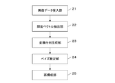
本実施の形態の画像再構成装置1の制御部11は、機能的には図2に例示するように、画像データ受入部21と、輝度ベクトル抽出部22と、変換行列生成部23と、ベイズ推定部24と、再構成部25とを含んで構成されている。画像データ受入部21は、入力部13から複数(例えばK個)の投影像の画像データの入力を受け入れ、それぞれを記憶部12に蓄積して格納する。ここで投影像の画像データはそれぞれ複数の画素値(検出素子ごとの出力値)を表すデータを含む。この画素値のデータは、例えば輝度の値を含む。
輝度ベクトル抽出部22は、画像データ受入部21が記憶部12に格納したk番目(k=1,2,…,K)の画像データの各々について、予め定めた順に画素値のデータ(例えば輝度の値)を配列して、輝度値ベクトルy(k)(k=1,2,…,K)を得る。このK個の輝度値ベクトルの集合D={y(k)}がサイノグラム(sinogram)に相当する。
変換行列生成部23は、ベイズ推定に用いる事前分布に係る演算式を生成する。すなわち、元の画像(断面像)を表す輝度ベクトルをxとし、投影像を得るためのラドン変換を表す投影変換行列をW(k)、撮像時の条件により生じる誤りをε(k)として、

と表すことができる。すなわち、

ここで、元の画像である断面像と投影像との対応関係、つまり元の画像の輝度ベクトルxからサイノグラムDが得られる確率を表す尤度関数p(D|x)は、投影変換行列W(k)により一意に定まる部分を除いた部分(ε(k)=W(k)D-x)、誤り(ノイズ)ε(k)の生じる確率p(ε(k))に等しいから、

を得る。ここでβは精度(分散の逆数)であり、IはW(k)と同じ次元の単位行列、Mはy(k)の次元、N(y(k)|a,b)は平均ベクトルa、分散行列をbとする分布関数である。この分布関数は具体的にはガウス分布やポアソン分布など広く知られた分布関数のうちから、予め利用者が選択しておく。
また変換行列生成部23は、投影変換行列W(k)を、少なくとも一つのアフィン変換を表す行列(平行移動、回転、縮小拡大等を表す行列)またはそれらの積(複数の場合)として、例えば次のように定める。すなわち観測対象から投影像が得られるまでの過程に係る条件として、k番目の投影像を得たときの角度をθk、投影像のサイズ(輝度ベクトルの次元)をM、観測対象の元の像のサイズ(輝度ベクトルの次元)をN、撮像により点像が、投影像においていかなるサイズの円盤像に投影されるかを表す、円盤像の幅、つまり、点広がり関数(point spread function)の大きさγを用い、当該θkの回転を表す行列R(θk)、ξだけ平行移動をすることを表す行列をT(ξ)、r倍の拡大縮小を表す行列をM(r)として、まず行列

を求める。この行列F(k)は、位置

にある画素を所定の位置に移動したうえで、θkだけ回転させ、r(r=M/N)倍して、

を当該r倍した位置まで再度移動することを意味する。これにより、次のように画素ベクトルの要素vjを変換すれば、投影像上の画素値uj(k)が得られる。
そしてこのuj(k)を用いた

により、投影変換行列W(k)の要素を次のように表すことができる。

また変換行列生成部23は、観測対象の像に関する制約条件に基づく事前分布(つまり元の画像である断面像自体の評価関数)を表す演算式p(x)を生成する。具体的にこの分布は次のように定められる。すなわち観測対象の像(再構成されるべき像)においては画素間に相関があり、互いに隣接する画素同士では輝度の差が所定の閾値を超えないとする。このようなp(x)としては、例えばガウス分布がある(次式)。

なお、分散を表す固定行列(fixed matrix)Zxは、

であり、ここにviは位置iにある画素値(ここでは輝度の値)、rは画素間の距離、Aは経験的に定められる係数である。変換行列生成部23は、これら生成したp(D|x)、及びp(x)に係る演算式(2),(4)式を、確率的モデルを表す演算式として出力する。また、このp(x)としては、ポアソン分布等、他の分布を用いてもよい。
ベイズ推定部24は、ベイズ推定を用いて事後分布p(x|D)を演算する。これは、再構成されるべき元の画像である断面像自体の評価関数と、断面像と投影像との関係に基づく評価関数とのそれぞれの値を最大化するような画像を断面像の推定結果として探索することに相当する。具体的にはベイズの定理から、

であり、このうち分母のp(D)は、すべてのxについて分子のp(x)・p(D|x)の和をとったものに他ならないから、予め規格化して「1」としておく。すると、サイノグラムDが与えられたとき、像がxである確率を与える事後分布p(x|D)は結局、

となる。ここにμは平均のベクトルである。ベイズ推定部24は、この(7)式に含まれる平均ベクトルμを演算する。この平均ベクトルμは、

である。ここに、Σは分散行列であり、
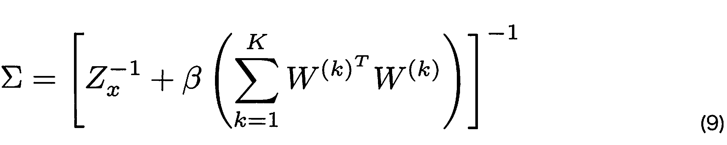
と表される。再構成部25は、平均のベクトルμを像の輝度のベクトルとして演算し、出力する。
本実施の形態の画像再構成装置1は、以上の構成を備えてなり、次のように動作する。すなわち、既知である64×64画素の2次元画像Sに対し、その中心まわりに、予め定めた角度から、角度θk(k=1,2,…,K)だけ傾いた走査方向に沿って、当該走査方向に対し垂直な線分に射影した、それぞれn画素の複数の像(この場合は複数の一次元像)Y1,Y2,…,YKを得る(図3)。
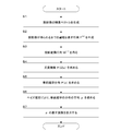
本実施の形態の画像再構成装置1は、図4に示す処理を行い、これらの、それぞれn画素分の複数の一次元像を受け入れる。そして、各一次元像のそれぞれの画素の輝度値を配列した複数のn次元のベクトルy1,y2,…,ykを得る(S1)。なお、ここでは輝度値としているが、カラーの場合、予め定めた色空間上の値(例えばR、G、Bの各値)のベクトルとしてもよい。
また画像再構成装置1は、観測対象から投影像が得られるまでの過程に係る条件として、k番目の投影像を得たときの角度をθk、投影像のサイズ(輝度ベクトルの次元)をM、観測対象の元の像のサイズ(輝度ベクトルの次元)をN、撮像により点像が、投影像においていかなるサイズの円盤像に投影されるかを表す、円盤像の幅、つまり、点広がり関数(point spread function)の大きさγを用い、当該θkの回転を表す行列R(θk)、ξだけ平行移動をすることを表す行列をT(ξ)として、(3)式で表される行列F(k)を求める(S2)。
そして画像再構成装置1は、このF(k)により画素ベクトルの要素vjを変換して投影像上の画素値uj(k)を得て、このuj(k)を用いて要素を定めた投影変換行列W(k)を得る(S3)。そしてこの行列を用いてベイズ推定に用いる尤度関数、p(D|x)を(2)式のように求める(S4)。
また画像再構成装置1は、観測対象の像に関する制約条件に基づく事前分布を表す演算式p(x)を生成し((4)式)(S5)、これら生成したp(D|x)、及びp(x)に係る演算式(2),(4)式を確率的モデルを表す演算式とし、ベイズ推定の式((6)式)を用いて、事後推定の結果である平均ベクトルμを(8)式により演算する(S6)。画像再構成装置1は、この平均ベクトルμの表す像を再構成した画像として出力する(S7)。
ここで平均ベクトルμは、再構成した画像に含まれるべき画素の輝度値(画素値)を予め定めた順に配列してベクトルとしたものであるから、当該順に従って元の画像の各画素の値を、当該平均ベクトルμにおける対応する成分の値から定める(例えばその値そのものとする)ことで、元の画像が得られる。
このような本実施の形態によると、元となる観測対象の断面像から投影像が得られるプロセスをそのまま観測画像の生成の確率的モデルとして記述することで、ベイズ統計学に基づく演算により、投影像から最尤断面像(観測対象の画像)を直接的に推定する。また、これより、投影変換行列を観測対象から投影像が得られるまでの過程に係る条件に基づいて設定することで、例えばヘリカルスキャン、コーンビーム、マルチCT、位相CT、3次元CT等の種々の投影過程による投影像を対象として再構成像が得られる。
さらに本実施の形態の画像再構成装置1は、ラドン変換を表す投影変換行列W(k)を演算するにあたり、観測対象から投影像が得られるまでの過程に係る条件を表す演算式として、(3)式に定めた行列F(k)に代えて、次のような行列F(k)を用いることとしてもよい。すなわち、k番目の投影像を得たときの角度をθk、投影像のサイズ(輝度ベクトルの次元)をM、観測対象の元の像のサイズ(輝度ベクトルの次元)をN、撮像により点像が、投影像においていかなるサイズの円盤像に投影されるかを表す、円盤像の幅、つまり、点広がり関数(point spread function)の大きさγを用い、当該θkの回転を表す行列R(θk)、ξだけ平行移動をすることを表す行列をT(ξ)、さらにk番目の投影像を得たときの位置ズレを表すシフトベクトルSkによる平行移動T(Sk)を含め、

としてもよい。
この行列F(k)は、k番目の投影像を撮像したときにSkだけの位置ズレが生じたとしたものであるが、実際には、この位置ズレの量Skは、外乱であるために測定が困難である。また、θk、γについても予め定めたものから、外乱のために実際の撮影時にはずれている可能性もある。すなわち、Sk,θk,γは、未知のパラメータであるということができる。
そこで本実施の形態の画像再構成装置1は、これら未知のパラメータを、いわゆるEMアルゴリズム(期待値最大化法)や、直接推定の方法を用いて推定する。EMアルゴリズムを用いる場合、未知パラメータのセットをα

とおく。これにより、最終的に求めたい確率的モデルを表す演算式の一つの対数値

を考え、この期待値を最大化する。
すなわち画像再構成装置1は、当初は、この未知パラメータのセットの初期値αt=α0を仮に定める。当初はSk,γを0、θkはk番目の投影像を得たときのX線の飛跡方向を表す角度、つまり撮影時の設定角度としておいてもよいし、ランダムに決定してもよい。
そして画像再構成装置1は、未知パラメータのセットがαtであるとき、期待値を評価するステップ(Eステップ)では、(11)式のうち、αtに係る項である

を演算する。以下この(12)式を最大化することを考える。そしてこの(12)式の期待値を最大化するステップ(Mステップ)として、(12)式を最大化するαを求め、これを次の未知パラメータのセットαt+1とする。すなわち、

とする。
画像再構成装置1は、このαが収束するまで、つまり、ベクトルαt+1-αtの大きさが予め定めたしきい値を下回るまで、EステップとMステップとを交互に繰り返し実行する。そして収束後のαが得られれば、当該αに含まれる未知パラメータの値を用いて、行列F(k)を求め、さらには投影変換行列W(k)を求めて、尤度関数p(D|x)を定める。
また、この未知パラメータを推定する方法として、画像再構成装置は、周辺尤度を最大化するαを直接的に求めてもよい。すなわち周辺尤度を

として、これを最大化するαを求める

こととしてもよい。
またCT撮影では、金属が含まれる生体組織の投影像を得た場合など、当該金属における高いX線吸収率により、投影像にデータが欠損した領域が生じる場合がある。これは例えば金属製のクラウン(歯科で用いる被せ物)が含まれる口腔を撮像した場合等にあり得るが、従来の方法では当該欠損した領域により生じるアーチファクト(いわゆるメタル・アーチファクト)が避け得なかった。本実施の形態の画像再構成装置1では、観測対象の像に関する制約条件に基づく事前分布p(x)として、当該欠損した領域を含んだ推定像のエッジを表現するイジングモデル等を用いることなどとすることで、このメタル・アーチファクトを軽減する。
そのほか、この投影変換行列W(k)を求める際の行列F(k)に含めることのできる未知パラメータとして、投影像の撮像に用いた撮像素子等の特性(感度など)があり、観測対象の像に関する制約条件に基づく事前分布p(x)を定める際に、推定される断面に含まれるべき物体のX線吸収率などの物質の特性を表す情報等、種々のものを利用できる。これにより、予め分かっている観測対象の像(断面像)に関する情報を有効に利用して断面像の再構成の処理を行うことができる。また、投影変換行列W(k)を求める際の行列F(k)に得られる画像の解像度に係るパラメータを含むので、投影像よりも解像度の高い画像を再構成する、いわゆる超解像処理を行うこととしてもよい。
さらに、撮像角度が制限されている場合や、撮像対象の内部に、検出素子で検出する電磁波や粒子線源がある場合(蛍光体がある場合)、これら検出素子で検出する電磁波や粒子線を散乱ないし吸収する物質が撮像対象の内部に含まれている場合には、観測対象から投影像が得られるまでの過程に係る条件を表現した行列F(k)を生成するときに、それぞれの条件を表す行列を乗じたものとして生成すればよい。
また撮像時にゾーンプレートを用いている場合など、非線形な散乱が発生する場合は、当該非線形な散乱を線形に近似した行列Lを作成する。そしてこの行列Lを含む行列の積により、(3)または(10)式に示したものと同様に、行列F(k)を得る。また隣接する検出素子間で出力値に相関がある場合も、その旨を表す行列を含む複数の行列の積により、行列F(k)を得る。
さらに、本実施の形態では、投影像を得るまでの過程がわかっていれば、いままでに得られているCTデータから再構成した画像を得てもよい
さらに、本実施の形態では、投影像を得るまでの過程がわかっていれば、いままでに得られているCTデータから再構成した画像を得てもよい
さらに電子線やX線を利用したCT等ではビームハードニング(Beam Hardening)アーチファクトの影響がある。これら検出素子で検出する電磁波や粒子線は一般に単波長ではなく、比較的波長の長い成分から短い成分まで種々の波長の電磁波や物質波(ド・ブロイ波)を含むものである。このビームハードニングは、これらX線等が撮像対象を透過する間に、比較的波長の長い成分がより吸収されて、透過に従って短い波長の成分が多くなり、結果としてエネルギーが高くなる現象をいう。
医療用にCTを用いる場合にこの現象が発生すると、体内に実在しない低吸収領域があるように見えてしまう場合がある。
そこで(3)または(10)式に示したような、行列F(k)を行列の積のうちに、ビームハードニング(X線等のエネルギーの減衰)に伴うCTデータの変化を表す行列を含める。
医療用にCTを用いる場合にこの現象が発生すると、体内に実在しない低吸収領域があるように見えてしまう場合がある。
そこで(3)または(10)式に示したような、行列F(k)を行列の積のうちに、ビームハードニング(X線等のエネルギーの減衰)に伴うCTデータの変化を表す行列を含める。
具体的には、行列F(k)を、k番目の投影像の撮像過程で生じる、投影対象の各部分における、波長に依存した電磁波または粒子線のエネルギーの減衰量を未知パラメータとして含む行列A(aλ1,aλ2…)と、その他、撮像過程での変換を表す行列M(r)、T(Sk)等との積により表すこととすればよい。ここで、aλnは、予め定めた複数の波長(例えば、吸収率が互いに異なると考えられる各周波数帯から少なくとも一つずつの代表波長を選択することにより定めればよい)λ1,λ2,…λnの成分ごとの吸収係数(波長λi(i=1,2,…)の成分の減衰割合)を意味する。つまり、この行列を含んだ複数の行列の積で表される行列F(k)は、検出素子ごとの出力値である画素値を、多次元の吸収係数で表現するものとなる。これにより、波長帯ごとの吸収率を推定し、波長帯ごとの吸収率の相違によって発生するアーチファクトなどを軽減する。
このように、観測対象から投影像が得られるまでの過程に係る種々の条件を表した行列F(k)を生成することで、種々の撮像態様や、撮像対象の性質を反映した画像の再構成を行ってもよい。
このように、観測対象から投影像が得られるまでの過程に係る種々の条件を表した行列F(k)を生成することで、種々の撮像態様や、撮像対象の性質を反映した画像の再構成を行ってもよい。
本発明の実施例として、画像再構成装置1を、制御部11であるCPUとしてIntel Xeno 2.66GHz(4コア)を採用したコンピュータを用いて実現した例を次に示す。
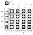
図5は、元の64×64画素の二次元像(A)について得た32×8、32×16、32×32、32×64画素のサイノグラム(R)を得て、それぞれ単純に逆ラドン変換を行って得た再構成画像(B)、フィルタを用いた再構成画像(C)、逐次近似法による再構成画像(D)、本実施例の画像再構成装置1により得た再構成画像(E)を対比したものである。
図5において、各再構成画像(B,C,D,E)は上から順に、それぞれ32×8、32×16、32×32、32×64画素のサイノグラムから得られる再構成画像を表す。
図5において、各再構成画像(B,C,D,E)は上から順に、それぞれ32×8、32×16、32×32、32×64画素のサイノグラムから得られる再構成画像を表す。
この図5の例において、再構成画像C,D,Eを表すベクトル(xにハット(^)を付している)と、原画像xと、単純に逆ラドン変換を行って得た再構成画像を表すベクトル(xにチルド(~)を付している)とを用いて演算される再現性の評価値ISNR(式(16))
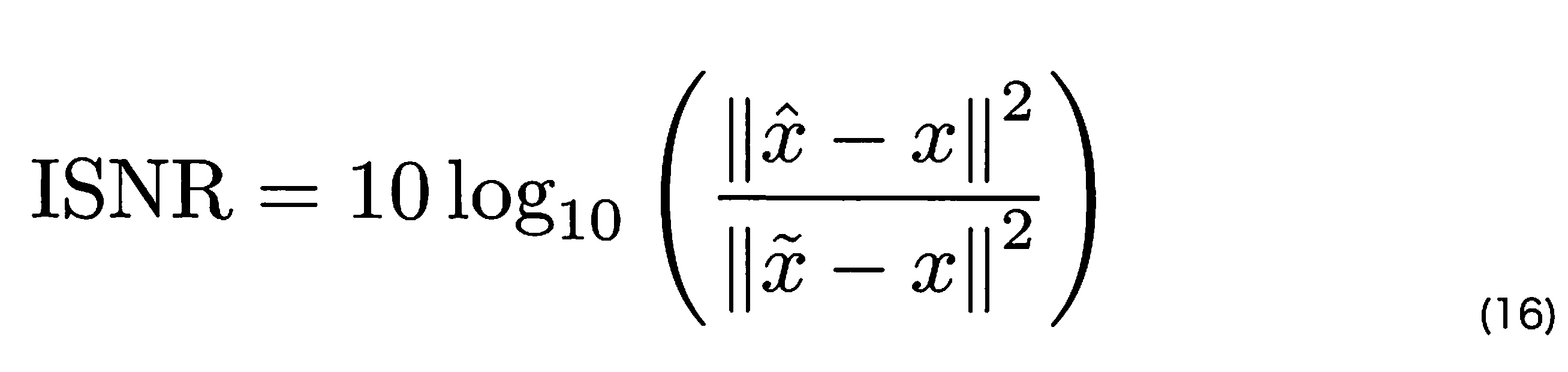
を得た結果を、図6に示す。図6において、横軸はサイノグラムのサイズ、縦軸はISNR値を示す。
図6に例示するように、本実施例の方法によると、フィルタを用いる例や逐次近似を用いる例に比べ、再現性を大幅に改善できる。
1 画像再構成装置、11 制御部、12 記憶部、13 入力部、14 出力部、21 画像データ受入部、22 輝度ベクトル抽出部、23 変換行列生成部、24 ベイズ推定部、25 再構成部。
Claims (3)
- 観測対象に対して互いに異なる方向から得た、観測対象を透過した複数の投影像に係る画像データを受け入れる手段と、
前記観測対象の像の画素間に、予め定めた相関があることを表す分布関数と、当該観測対象に基づいて投影像が得られるまでの過程に係る条件とに基づいて、前記投影像を生成する確率的モデルを表す演算式を生成する手段と、
ベイズ推定を用いて、前記確率的モデルを表す演算式と、前記画像データとから観測対象の断面像を推定する手段と、
を含む画像再構成装置。 - 請求項1記載の画像再構成装置であって、
前記確率的モデルを表す演算式を生成する手段は、前記観測対象に基づいて投影像が得られるまでの過程に係る条件として、撮影時の外乱による未知パラメータを含む条件を表す演算式を生成する手段であり、
当該未知パラメータを推定する手段をさらに含む画像再構成装置。 - 請求項1または2記載の画像再構成装置であって、
前記投影像は、観測対象を透過する電磁波または粒子線を検出することによって得たものであり、
前記確率的モデルを表す演算式を生成する手段は、前記観測対象の透過に伴う前記電磁波または粒子線の、波長に依存したエネルギーの減衰が、前記投影像にもたらす影響を表す変換行列を用いて、演算式である投影変換行列を生成することを特徴とする画像再構成装置。
Applications Claiming Priority (2)
| Application Number | Priority Date | Filing Date | Title |
|---|---|---|---|
| JP2011138833A JP2013005840A (ja) | 2011-06-22 | 2011-06-22 | 画像再構成装置及びプログラム |
| JP2011-138833 | 2011-06-22 |
Publications (1)
| Publication Number | Publication Date |
|---|---|
| WO2012176754A1 true WO2012176754A1 (ja) | 2012-12-27 |
Family
ID=47422590
Family Applications (1)
| Application Number | Title | Priority Date | Filing Date |
|---|---|---|---|
| PCT/JP2012/065592 Ceased WO2012176754A1 (ja) | 2011-06-22 | 2012-06-19 | 画像再構成装置 |
Country Status (2)
| Country | Link |
|---|---|
| JP (1) | JP2013005840A (ja) |
| WO (1) | WO2012176754A1 (ja) |
Families Citing this family (2)
| Publication number | Priority date | Publication date | Assignee | Title |
|---|---|---|---|---|
| WO2014185078A1 (ja) * | 2013-05-15 | 2014-11-20 | 国立大学法人京都大学 | X線ct画像処理方法,x線ct画像処理プログラム及びx線ct画像装置 |
| FR3015681B1 (fr) * | 2013-12-20 | 2016-04-22 | Commissariat Energie Atomique | Methode de mesure du numero atomique effectif d'un materiau |
-
2011
- 2011-06-22 JP JP2011138833A patent/JP2013005840A/ja not_active Withdrawn
-
2012
- 2012-06-19 WO PCT/JP2012/065592 patent/WO2012176754A1/ja not_active Ceased
Non-Patent Citations (2)
| Title |
|---|
| MADOMI YAMASAKI ET AL.: "Bayesian Reconstruction for Computed Tomography using 3 Dimensional Markov Random Field", IEICE TECHNICAL REPORT, vol. 111, no. 47, 12 May 2011 (2011-05-12), pages 45 - 50 * |
| SHIN'ICHI MAEDA ET AL.: "Bayesian modeling of medical X-ray computed tomography", IEICE TECHNICAL REPORT, vol. 110, no. 280, 8 November 2010 (2010-11-08), pages 39 - 44 * |
Also Published As
| Publication number | Publication date |
|---|---|
| JP2013005840A (ja) | 2013-01-10 |
Similar Documents
| Publication | Publication Date | Title |
|---|---|---|
| US10292672B2 (en) | Radiographic image processing device, method, and recording medium | |
| Liu et al. | Total variation-stokes strategy for sparse-view X-ray CT image reconstruction | |
| EP3673457B1 (en) | A method of generating an enhanced tomographic image of an object | |
| Xu et al. | A practical cone-beam CT scatter correction method with optimized Monte Carlo simulations for image-guided radiation therapy | |
| JP5815048B2 (ja) | X線ct装置 | |
| Nuyts et al. | Modelling the physics in the iterative reconstruction for transmission computed tomography | |
| La Riviere et al. | Reduction of noise-induced streak artifacts in X-ray computed tomography through spline-based penalized-likelihood sinogram smoothing | |
| US7831097B2 (en) | System and method for image reconstruction | |
| US8571287B2 (en) | System and method for iterative image reconstruction | |
| JP6312401B2 (ja) | 画像処理装置、画像処理方法、及びプログラム | |
| CN103156629B (zh) | 图像处理设备和图像处理方法 | |
| Tilley et al. | Penalized-likelihood reconstruction with high-fidelity measurement models for high-resolution cone-beam imaging | |
| EP3447721A1 (en) | A method of generating an enhanced tomographic image of an object | |
| Tilley et al. | Model-based material decomposition with a penalized nonlinear least-squares CT reconstruction algorithm | |
| US11935160B2 (en) | Method of generating an enhanced tomographic image of an object | |
| JP5590548B2 (ja) | X線ct画像処理方法,x線ctプログラムおよび該プログラムが搭載されたx線ct装置 | |
| EP3447731A1 (en) | A method of generating an enhanced tomographic image of an object | |
| US20110268334A1 (en) | Apparatus for Improving Image Resolution and Apparatus for Super-Resolution Photography Using Wobble Motion and Point Spread Function (PSF), in Positron Emission Tomography | |
| CN103052972A (zh) | 用于迭代图像重建的方法和系统 | |
| US10475215B2 (en) | CBCT image processing method | |
| JP2014518133A (ja) | 画像再構成方法とシステム{iterativeimagereconsgtruction} | |
| CN102270350A (zh) | 结合四维噪声滤波器的迭代ct图像重建 | |
| US6751284B1 (en) | Method and system for tomosynthesis image enhancement using transverse filtering | |
| US10891764B2 (en) | Image processing apparatus, image processing method, and image processing program | |
| JP2014147772A (ja) | モデルに基づく反復的再構成のための逆投影と順投影との少なくとも一方におけるシステムオプティクス |
Legal Events
| Date | Code | Title | Description |
|---|---|---|---|
| 121 | Ep: the epo has been informed by wipo that ep was designated in this application |
Ref document number: 12802214 Country of ref document: EP Kind code of ref document: A1 |
|
| NENP | Non-entry into the national phase |
Ref country code: DE |
|
| 122 | Ep: pct application non-entry in european phase |
Ref document number: 12802214 Country of ref document: EP Kind code of ref document: A1 |