WO2012172744A1 - Print head and inkjet printing apparatus - Google Patents
Print head and inkjet printing apparatus Download PDFInfo
- Publication number
- WO2012172744A1 WO2012172744A1 PCT/JP2012/003621 JP2012003621W WO2012172744A1 WO 2012172744 A1 WO2012172744 A1 WO 2012172744A1 JP 2012003621 W JP2012003621 W JP 2012003621W WO 2012172744 A1 WO2012172744 A1 WO 2012172744A1
- Authority
- WO
- WIPO (PCT)
- Prior art keywords
- print head
- ejection opening
- photopolymer layer
- liquid
- ejection
- Prior art date
- Legal status (The legal status is an assumption and is not a legal conclusion. Google has not performed a legal analysis and makes no representation as to the accuracy of the status listed.)
- Ceased
Links
Images
















Classifications
-
- B—PERFORMING OPERATIONS; TRANSPORTING
- B41—PRINTING; LINING MACHINES; TYPEWRITERS; STAMPS
- B41J—TYPEWRITERS; SELECTIVE PRINTING MECHANISMS, i.e. MECHANISMS PRINTING OTHERWISE THAN FROM A FORME; CORRECTION OF TYPOGRAPHICAL ERRORS
- B41J2/00—Typewriters or selective printing mechanisms characterised by the printing or marking process for which they are designed
- B41J2/005—Typewriters or selective printing mechanisms characterised by the printing or marking process for which they are designed characterised by bringing liquid or particles selectively into contact with a printing material
- B41J2/01—Ink jet
- B41J2/135—Nozzles
- B41J2/14—Structure thereof only for on-demand ink jet heads
-
- B—PERFORMING OPERATIONS; TRANSPORTING
- B41—PRINTING; LINING MACHINES; TYPEWRITERS; STAMPS
- B41J—TYPEWRITERS; SELECTIVE PRINTING MECHANISMS, i.e. MECHANISMS PRINTING OTHERWISE THAN FROM A FORME; CORRECTION OF TYPOGRAPHICAL ERRORS
- B41J2/00—Typewriters or selective printing mechanisms characterised by the printing or marking process for which they are designed
- B41J2/005—Typewriters or selective printing mechanisms characterised by the printing or marking process for which they are designed characterised by bringing liquid or particles selectively into contact with a printing material
- B41J2/01—Ink jet
- B41J2/135—Nozzles
- B41J2/14—Structure thereof only for on-demand ink jet heads
- B41J2/14016—Structure of bubble jet print heads
- B41J2/14032—Structure of the pressure chamber
- B41J2/1404—Geometrical characteristics
-
- B—PERFORMING OPERATIONS; TRANSPORTING
- B41—PRINTING; LINING MACHINES; TYPEWRITERS; STAMPS
- B41J—TYPEWRITERS; SELECTIVE PRINTING MECHANISMS, i.e. MECHANISMS PRINTING OTHERWISE THAN FROM A FORME; CORRECTION OF TYPOGRAPHICAL ERRORS
- B41J2/00—Typewriters or selective printing mechanisms characterised by the printing or marking process for which they are designed
- B41J2/005—Typewriters or selective printing mechanisms characterised by the printing or marking process for which they are designed characterised by bringing liquid or particles selectively into contact with a printing material
- B41J2/01—Ink jet
- B41J2/135—Nozzles
- B41J2/16—Production of nozzles
- B41J2/1601—Production of bubble jet print heads
- B41J2/1603—Production of bubble jet print heads of the front shooter type
-
- B—PERFORMING OPERATIONS; TRANSPORTING
- B41—PRINTING; LINING MACHINES; TYPEWRITERS; STAMPS
- B41J—TYPEWRITERS; SELECTIVE PRINTING MECHANISMS, i.e. MECHANISMS PRINTING OTHERWISE THAN FROM A FORME; CORRECTION OF TYPOGRAPHICAL ERRORS
- B41J2/00—Typewriters or selective printing mechanisms characterised by the printing or marking process for which they are designed
- B41J2/005—Typewriters or selective printing mechanisms characterised by the printing or marking process for which they are designed characterised by bringing liquid or particles selectively into contact with a printing material
- B41J2/01—Ink jet
- B41J2/135—Nozzles
- B41J2/16—Production of nozzles
- B41J2/1621—Manufacturing processes
- B41J2/1631—Manufacturing processes photolithography
-
- B—PERFORMING OPERATIONS; TRANSPORTING
- B41—PRINTING; LINING MACHINES; TYPEWRITERS; STAMPS
- B41J—TYPEWRITERS; SELECTIVE PRINTING MECHANISMS, i.e. MECHANISMS PRINTING OTHERWISE THAN FROM A FORME; CORRECTION OF TYPOGRAPHICAL ERRORS
- B41J2/00—Typewriters or selective printing mechanisms characterised by the printing or marking process for which they are designed
- B41J2/005—Typewriters or selective printing mechanisms characterised by the printing or marking process for which they are designed characterised by bringing liquid or particles selectively into contact with a printing material
- B41J2/01—Ink jet
- B41J2/135—Nozzles
- B41J2/16—Production of nozzles
- B41J2/1621—Manufacturing processes
- B41J2/1637—Manufacturing processes molding
- B41J2/1639—Manufacturing processes molding sacrificial molding
-
- B—PERFORMING OPERATIONS; TRANSPORTING
- B41—PRINTING; LINING MACHINES; TYPEWRITERS; STAMPS
- B41J—TYPEWRITERS; SELECTIVE PRINTING MECHANISMS, i.e. MECHANISMS PRINTING OTHERWISE THAN FROM A FORME; CORRECTION OF TYPOGRAPHICAL ERRORS
- B41J2/00—Typewriters or selective printing mechanisms characterised by the printing or marking process for which they are designed
- B41J2/005—Typewriters or selective printing mechanisms characterised by the printing or marking process for which they are designed characterised by bringing liquid or particles selectively into contact with a printing material
- B41J2/01—Ink jet
- B41J2/135—Nozzles
- B41J2/14—Structure thereof only for on-demand ink jet heads
- B41J2/14016—Structure of bubble jet print heads
- B41J2002/14169—Bubble vented to the ambience
-
- B—PERFORMING OPERATIONS; TRANSPORTING
- B41—PRINTING; LINING MACHINES; TYPEWRITERS; STAMPS
- B41J—TYPEWRITERS; SELECTIVE PRINTING MECHANISMS, i.e. MECHANISMS PRINTING OTHERWISE THAN FROM A FORME; CORRECTION OF TYPOGRAPHICAL ERRORS
- B41J2/00—Typewriters or selective printing mechanisms characterised by the printing or marking process for which they are designed
- B41J2/005—Typewriters or selective printing mechanisms characterised by the printing or marking process for which they are designed characterised by bringing liquid or particles selectively into contact with a printing material
- B41J2/01—Ink jet
- B41J2/135—Nozzles
- B41J2/14—Structure thereof only for on-demand ink jet heads
- B41J2002/14475—Structure thereof only for on-demand ink jet heads characterised by nozzle shapes or number of orifices per chamber
-
- B—PERFORMING OPERATIONS; TRANSPORTING
- B41—PRINTING; LINING MACHINES; TYPEWRITERS; STAMPS
- B41J—TYPEWRITERS; SELECTIVE PRINTING MECHANISMS, i.e. MECHANISMS PRINTING OTHERWISE THAN FROM A FORME; CORRECTION OF TYPOGRAPHICAL ERRORS
- B41J2202/00—Embodiments of or processes related to ink-jet or thermal heads
- B41J2202/01—Embodiments of or processes related to ink-jet heads
- B41J2202/11—Embodiments of or processes related to ink-jet heads characterised by specific geometrical characteristics
-
- Y—GENERAL TAGGING OF NEW TECHNOLOGICAL DEVELOPMENTS; GENERAL TAGGING OF CROSS-SECTIONAL TECHNOLOGIES SPANNING OVER SEVERAL SECTIONS OF THE IPC; TECHNICAL SUBJECTS COVERED BY FORMER USPC CROSS-REFERENCE ART COLLECTIONS [XRACs] AND DIGESTS
- Y10—TECHNICAL SUBJECTS COVERED BY FORMER USPC
- Y10T—TECHNICAL SUBJECTS COVERED BY FORMER US CLASSIFICATION
- Y10T29/00—Metal working
- Y10T29/49—Method of mechanical manufacture
- Y10T29/49401—Fluid pattern dispersing device making, e.g., ink jet
Definitions
- the present invention relates to a print head which ejects a liquid of ink or the like on various types of medium for printing, and an inkjet printing apparatus using the print head.
- thermoelectric conversion element thermoelectric conversion element
- the downsizing of the liquid drop ejected from the print head has been made. Due to the small-sized liquid drop, there is a tendency that an influence of a phenomenon where liquid drops ejected from the print head are divided into liquid drops (hereinafter, called main drops) which should be originally used for printing and side minuscule liquid drops (hereinafter, called satellites) is noticeable. For example, there are some cases where degradation of image quality is caused by the event that the satellite lands on a print medium. Further, the satellite loses its speed before reaching the print medium to be formed as floating liquid drops (hereinafter, called mists), possibly causing contamination of the printing apparatus or the print medium.
- mists floating liquid drops
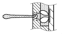
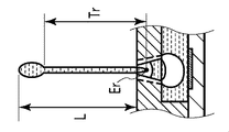
- PTL 1 discloses a technology that an ejection opening is formed in a non-circular shape, for example, in a sand clock shape to partially reduce a dimension of an opening part of the ejection opening, whereby meniscus forces are increased, which reduces stir of a liquid surface from the ejection opening to shorten the ink tail.
- PTL 1 discloses the technology that the dimension of the opening part of the ejection opening is partially reduced for the satellite reduction.
- the construction in PTL 1 assumes the ejection opening having a larger dimension than the ejection opening used in the recent print head for high image quality.
- PTL 1 does not refer to an ejection defect at a printing start and has no descriptions of the improvement. That is, factors causing the ejection defect of the liquid at the printing start include the event that the liquid in the ejection opening is vaporized while the printing is stopped, to increase the viscosity, which makes the liquid difficult to be ejected.
- the ejection defect of the liquid at the printing start is generated depending on the configuration in the ejection opening.
- An object of the present invention is to provide a print head which is provided with ejection openings for achieving both of a reduction of phenomena of satellites and mists and an improvement on an ejection defect at a printing start and is capable of printing with high quality, and an inkjet printing apparatus provided with the print head.
- the print head according to the present invention includes the ejection opening which is sized to be larger from an outlet side toward an inside of the print head and has the projections capable of holding a surface of the meniscus of the liquid formed inside of the ejection opening in the liquid ejecting process, in the vicinity of the outlet in the ejection opening.
- the print head according to the present invention with such a construction can shorten a length of the ink tail in the liquid drop ejected, thus reducing the satellite and mist, and on the other hand, provide ejection stability at a printing start.
- Fig. 1 is a schematic perspective view of a print head according to an embodiment in the present invention
- Fig. 2 is a cross section of the print head taken along line II - II' in Fig. 1
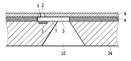
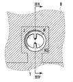
- Fig. 3A is a front view of an ejection opening of the print head according to a first embodiment
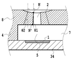
- Fig. 3B is a cross section of the ejection opening in the print head taken along line IIIB - IIIB' in Fig. 3A
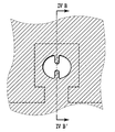
- Fig. 4A is a front view of an ejection opening in a print head according to a comparative example
- Fig. 4B is a cross section of the ejection opening in the print head taken along line IVB - IVB' in Fig. 4A
- Fig. 1 is a schematic perspective view of a print head according to an embodiment in the present invention
- Fig. 2 is a cross section of the print head taken along line II - II' in Fig. 1
- Fig. 3A is a front view of an e
- FIG. 5A is a diagram showing the ink ejection process of the print head according to the first embodiment
- Fig. 5B is a diagram showing the ink ejection process of the print head according to the first embodiment
- Fig. 5C is a diagram showing the ink ejection process of the print head according to the first embodiment
- Fig. 5D is a diagram showing the ink ejection process of the print head according to the first embodiment
- Fig. 5E is a diagram showing the ink ejection process of the print head according to the first embodiment
- Fig. 5F is a diagram showing the ink ejection process of the print head according to the first embodiment
- Fig. 5G is a diagram showing the ink ejection process of the print head according to the first embodiment
- Fig. 5G is a diagram showing the ink ejection process of the print head according to the first embodiment
- Fig. 5G is a diagram showing the ink ejection process of the print head according to the first embodiment
- FIG. 5AR is a diagram showing the ink ejection process of the print head according to the comparative example
- Fig. 5BR is a diagram showing the ink ejection process of the print head according to the comparative example
- Fig. 5CR is a diagram showing the ink ejection process of the print head according to the comparative example
- Fig. 5DR is a diagram showing the ink ejection process of the print head according to the comparative example
- Fig. 5ER is a diagram showing the ink ejection process of the print head according to the comparative example
- Fig. 5FR is a diagram showing the ink ejection process of the print head according to the comparative example
- Fig. 5AR is a diagram showing the ink ejection process of the print head according to the comparative example
- Fig. 5BR is a diagram showing the ink ejection process of the print head according to the comparative example
- Fig. 5CR is a diagram showing the ink ejection process of the print head according to
- 5GR is a diagram showing the ink ejection process of the print head according to the comparative example
- Fig. 6A is a diagram showing a method of forming the ejection opening in the print head according to the first embodiment
- Fig. 6B is a diagram showing a method of forming the ejection opening in the print head according to the first embodiment
- Fig. 6C is a diagram showing a method of forming the ejection opening in the print head according to the first embodiment
- Fig. 6D is a diagram showing a method of forming the ejection opening in the print head according to the first embodiment
- Fig. 6E is a diagram showing a method of forming the ejection opening in the print head according to the first embodiment
- Fig. 6A is a diagram showing a method of forming the ejection opening in the print head according to the first embodiment
- Fig. 6B is a diagram showing a method of forming the ejection opening in the print head according to the first embodiment
- FIG. 6F is a diagram showing a method of forming the ejection opening in the print head according to the first embodiment
- Fig. 6G is a diagram showing a method of forming the ejection opening in the print head according to the first embodiment
- Fig. 6H is a diagram showing a method of forming the ejection opening in the print head according to the first embodiment
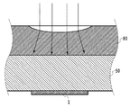
- Fig. 7 is a concept diagram of incident light at an ejection opening exposure time in the manufacture of the print head according to the first embodiment
- Fig. 8A is a diagram showing a method of forming an ejection opening in a print head according to a second embodiment
- Fig. 8B is a diagram showing a method of forming an ejection opening in a print head according to a second embodiment
- FIG. 8C is a diagram showing a method of forming an ejection opening in a print head according to a second embodiment
- Fig. 8D is a diagram showing a method of forming an ejection opening in a print head according to a second embodiment
- Fig. 8E is a diagram showing a method of forming an ejection opening in a print head according to a second embodiment
- Fig. 8F is a diagram showing a method of forming an ejection opening in a print head according to a second embodiment
- Fig. 8G is a diagram showing a method of forming an ejection opening in a print head according to a second embodiment
- Fig. 9 is a schematic perspective view of an inkjet printing apparatus according to a third embodiment.
- the print head includes a substrate 34, a flow passage forming portion 4 provided on one surface of the substrate 34, and an ejection opening plate 8 jointed onto the flow passage forming portion 4.
- Thermoelectric conversion elements 1 as ejection energy generating elements acting on ink ejection and ink supply ports 3 as elongated, rectangular openings are formed on the one surface of the substrate 34.
- the thermoelectric conversion elements 1 are arranged to form one row in the longitudinal direction in each of both sides of the ink supply port 3, preferably in a zigzag manner and with an interval between the thermoelectric conversion elements 1 being equal to a pitch of 600dpi.
- Ejection openings 2 penetrating through the ejection opening plate 8 are provided in the ejection opening plate 8 to correspond to the thermoelectric conversion elements 1.
- the substrate 34 is further provided with groove-shaped ink supply chambers 10 each communicated with the ink supply port 3 and having an opening on a surface of the substrate 34 opposite to the surface on which the thermoelectric conversion elements 1 are formed.
- the substrate 34 forms liquid flow passages 7 and bubble releasing chambers 5 together with the flow passage forming portion 4 and the ejection opening plate 8.
- the bubble releasing chamber 5 is provided on the thermoelectric conversion element 1 and the liquid flow passage 7 is formed to lead ink introduced via the ink supply port 3 from the ink supply chamber 10 to the bubble releasing chamber 5.
- the ejection opening 2 provided to penetrate through the ejection opening plate 8 is a tubular opening for establishing communication between the bubble releasing chamber 5 and an outside.
- a silicon substrate is used as the substrate 34, but a material of the substrate 34 is not particularly limited as long as the substrate 34 can function as a support body of ejection energy generating means (thermoelectric conversion element 1), a material layer (flow passage forming portion 4) forming the liquid flow passage, and the like.
- the ejection opening plate 8 and the flow passage forming portion 4 are made of the same material, but the similar effect can be obtained even if made of different materials.
- the thermoelectric conversion element (heater) is used as the energy generating element used for ejecting liquid drops, but, not limited thereto, an element capable of controlling ejection of liquid drops by an electrical signal, such as a piezo element, may be used.
- the outer surface of the ejection opening plate 8 corresponding to the upper surface of the ejection opening 2 is recessed in a concave shape, but since this recess is extremely small, an influence of the recess on ejection performance of the ejection opening can be ignored.
- the recess in the concave shape is formed in relation to a manufacturing method of the print head to be described later, and is not a necessary element in view of the effect in the present invention.
- Table 1 relates to evaluations of ejection stability at a printing start and shows a result where printing starts immediately after a predetermined printing stop time elapses, to measure whether or not ink is ejected normally.
- the used inks were three colors of cyan, magenta, and yellow.
- a mark A indicates normal ejection
- a mark B indicates non-ejection
- a mark C indicates deviation occurrence in the ejection direction.
- FIG. 5A shows a state of the ejection opening in a steady state.
- the heater thermoelectric conversion element 1
- Fig. 5B shows a bubble releasing and air-bubble inflating process
- Fig. 5C shows the maximum bubble releasing process.
- Fig. 5D shows a deforming process, wherein the air bubble is gradually contracted.
- the meniscus is generated in the ejection opening.
- the liquid forming the meniscus is pulled in the heater direction, and the liquid drops in the peripheral portion (including the outer edge portion) other than between the projections earlier than between the projections.
- the connection between the liquid forming the meniscus between the projections and the liquid which has dropped earlier is gradually thin, and further, when the process goes to the process shown in Fig. 5G, the liquid to be ejected is completely separated from the liquid forming the meniscus in the ejection opening and the liquid remains between the projections only.
- the length of the ink tail in the liquid to be ejected can be shorter, thus providing the print head having more excellent performance on a reduction of the satellite and mist generated from the ink tail portion.
- both of the ejection stability at the printing start and the reduction performance on the satellite and mist can be achieved in a balanced manner.
- thermoelectric conversion element 1 generating energy for ejecting ink is arranged on the substrate 34.
- thermoelectric conversion element 1 generating energy for ejecting ink is arranged on the substrate 34.
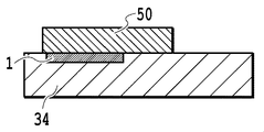
- a photopolymer is coated on the substrate 34 on which the thermoelectric conversion element 1 is arranged to form a first photopolymer layer 50 which is a mold of the bubble releasing chamber 5 and the liquid flow passage 7, and the photopolymer layer 50 is exposed and developed to pattern the bubble releasing chamber 5 and the liquid flow passage 7.
- a photopolymer is coated on the substrate 34 on which the thermoelectric conversion element 1 is arranged to form a first photopolymer layer 50 which is a mold of the bubble releasing chamber 5 and the liquid flow passage 7, and the photopolymer layer 50 is exposed and developed to pattern the bubble releasing chamber 5 and the liquid flow passage 7.
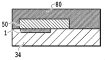
- the photopolymer is coated to cover the pattern of the bubble releasing chamber 5 and the liquid flow passage 7 to form a second photopolymer layer 80 which is designed to form the flow passage forming portion 4 and the ejection opening plate 8 in Fig. 1 integrally.
- the second photopolymer layer is exposed via a mask M in such a manner that the concave portion becomes a non-exposure portion.
- thermal treatment Post Exposure Bake
- the resin of the second photopolymer layer in the exposure portion exposed in the previous process is solidified and contracted.
- the resin of the second photopolymer layer in the non-exposure portion is heated to the softening point or more for softening, and, caused by the solidification and the contraction of the resin in the aforementioned exposure portion, the concave portion equivalent to the contracted volume is formed.
- the ejection opening with the projections is patterned by being exposed and developed in the concave portion formed in the previous process to produce the ejection opening in the concave portion.
- the concave configuration of the concave portion functions as lens due to a difference of a refractive index of light therebetween for incident light to be refracted (refer to Fig. 7).
- the refraction angle is determined by an inclination angle of the concave portion.
- the outer edge portion of the ejection opening is tapered by large refraction of light, and since part of the projection has small refraction, it is not tapered or almost not tapered.
- a diameter of the configuration of the concave portion can be changed by the mask, and a depth of the concave portion can be controlled by the exposure amount, and a temperature and a time of the thermal treatment. Therefore these factors can be adjusted as needed to correspond to a dimension of the ejection opening with the projections to be formed.
- the second embodiment shows different forming means of the ejection opening in the print head of the first embodiment, and has the same construction as that in the first embodiment in the other points. Therefore hereinafter, only the forming means of the ejection opening will be explained and the overlapped explanation is omitted.
- the exposure of the outer edge portion and the exposure of the projection in the ejection opening with the projections are respectively made separately.
- the first exposure is made to the second photopolymer layer 80 to form the outer edge portion in the ejection opening.
- the print head provided with the ejection opening excellent in both of the ejection stability at a printing start and the reduction performance of the satellite and the mist can be achieved.
- FIG. 9 is a schematic perspective view showing one construction example of an inkjet printing apparatus according to a third embodiment.
- the inkjet printing apparatus according to the third embodiment uses the print head having the same construction as that of the first embodiment as one example of the print head according to the present invention. Therefore an overlapped explanation will be hereinafter omitted.
- Ink tanks 205 to 208 respectively accommodate four colors of inks (cyan, magenta, yellow, and black), and are structured to supply the four colors of the inks to the print heads 201 to 204 in the first embodiment.
- the print heads 201 to 204 are provided corresponding to the four colors of the inks and are structured to eject the inks supplied from the ink tanks 205 to 208.
- ink drops ejected from each print element arranged in the print head are set to small ink drops of a fixed amount.
- a conveyance roller 103 rotates together with an auxiliary roller 104 while having a print medium (print sheet) 107 therebetween, and conveys and holds the print medium 107.
- a carriage 106 can mount the ink tanks 205 and 208 and the print heads 201 to 204, and reciprocally moves along the X direction while mounting the print heads and the ink tanks thereon. Ink is ejected from the print head during the reciprocal movement of the carriage 106, thereby printing an image on the print medium.
- the carriage 106 is controlled to wait in the home position h shown in a dotted line in the figure.
- the printing is performed onto a region having a width corresponding to an arrangement range of the ejection openings in the print head 201 by one time movement (scan) of the print head.
- scan main scan direction
- the conveyance roller 103 rotates to convey the printing medium in the sub scan direction (Y direction) intersecting with the main scan direction.
- the printing operation is performed only when the print head scans in the forward direction, that is, a case of performing so-called one-way printing is explained.
- the present invention can be applied to a print head of performing so-called bidirectional printing in which the print head performs printing at both scans in the forward and backward directions.
- the above example shows the structure that the ink tanks 205 to 208 and the print heads 201 to 204 are mounted in the carriage 106 to be separable.
- the structure of mounting on a carriage a cartridge where the ink tanks 205 to 208 and the print heads 201 and 204 are formed integrally.
- the inkjet printing apparatus is explained as a so-called serial type of inkjet printing apparatus for performing printing while the print head scans in the main scan direction (X direction).
- the print head used in the inkjet apparatus according to the present invention may be a full line type of print head for printing without scanning in the main scan direction.
- the print head to be used may be a single print head having a length corresponding to that of the print medium in the width direction or may be a combination of plural print heads.
- the print head according to the above embodiment is explained as the structure of using the ejection opening having two opposing projections each formed to be convex in the inside direction in a cross section perpendicular to the ejection direction of the liquid and having the parallel configuration in the ejection direction of the liquid and the outer edge portion having the tapered configuration in the ejection direction of the liquid.
- the ejection opening applicable to the print head according to the present invention is not limited thereto.
- the projection is only required to be capable of forming the meniscus of the liquid in the ejection opening at the time of ejecting the liquid from the ejection opening, and may be three or more projections.
- the positions of the projections are preferably provided equally in the inner periphery of the ejection opening. In a case where the number of the projections is an even number, the positions of the projections are preferably symmetrical in the inner periphery of the ejection opening.
Landscapes
- Engineering & Computer Science (AREA)
- Manufacturing & Machinery (AREA)
- Physics & Mathematics (AREA)
- Geometry (AREA)
- Particle Formation And Scattering Control In Inkjet Printers (AREA)
Abstract
A print head includes an energy generating element, a chamber for accommodating liquid, and an ejection opening for ejecting liquid from the chamber, thus applying the energy to the liquid in the chamber from the energy generating element to eject the liquid from the ejection opening, wherein the ejection opening includes at least two projections convex to an inside of the ejection opening in a cross section perpendicular to a liquid ejecting direction and has a tapered angle Θ 1 in regard to the liquid ejecting direction, enabling a meniscus of the liquid to be formed therebetween at the liquid ejecting time, and an outer edge portion has a tapered angle Θ 2 in regard to the liquid ejecting direction, wherein the tapered angles Θ 1 and Θ 2 are defined to meet a formula of 0° < Θ 1< 10° and a formula of Θ 2 > Θ 1.
Description
The present invention relates to a print head which ejects a liquid of ink or the like on various types of medium for printing, and an inkjet printing apparatus using the print head.
As to a method of ejecting a liquid of ink or the like, there is known a method of controlling an ejection energy generating element of a thermoelectric conversion element (heater) or the like by an electrical signal to eject liquid drops from an ejection opening of a print head.
In response to a recent demand for printing with high quality, the downsizing of the liquid drop ejected from the print head has been made. Due to the small-sized liquid drop, there is a tendency that an influence of a phenomenon where liquid drops ejected from the print head are divided into liquid drops (hereinafter, called main drops) which should be originally used for printing and side minuscule liquid drops (hereinafter, called satellites) is noticeable. For example, there are some cases where degradation of image quality is caused by the event that the satellite lands on a print medium. Further, the satellite loses its speed before reaching the print medium to be formed as floating liquid drops (hereinafter, called mists), possibly causing contamination of the printing apparatus or the print medium.
For a reduction of the satellite, for example, as described in PTL 1, it is known to shorten a length of an ink tail in the ejected liquid drop. PTL 1 discloses a technology that an ejection opening is formed in a non-circular shape, for example, in a sand clock shape to partially reduce a dimension of an opening part of the ejection opening, whereby meniscus forces are increased, which reduces stir of a liquid surface from the ejection opening to shorten the ink tail.
PTL 1: Japanese Patent Laid-Open No. H10-235874(1998)
An object of the present invention is to provide a print head which is provided with ejection openings for achieving both of a reduction of phenomena of satellites and mists and an improvement on an ejection defect at a printing start and is capable of printing with high quality, and an inkjet printing apparatus provided with the print head.

The print head according to the present invention includes the ejection opening which is sized to be larger from an outlet side toward an inside of the print head and has the projections capable of holding a surface of the meniscus of the liquid formed inside of the ejection opening in the liquid ejecting process, in the vicinity of the outlet in the ejection opening. The print head according to the present invention with such a construction can shorten a length of the ink tail in the liquid drop ejected, thus reducing the satellite and mist, and on the other hand, provide ejection stability at a printing start.
Further features of the present invention will become apparent from the following description of exemplary embodiments (with reference to the attached drawings).
An inkjet print head according to an embodiment in the present invention and an inkjet printing apparatus using the print head will be explained with reference to the drawings.

By referring to Fig. 1, the print head includes a substrate 34, a flow passage forming portion 4 provided on one surface of the substrate 34, and an ejection opening plate 8 jointed onto the flow passage forming portion 4. Thermoelectric conversion elements 1 as ejection energy generating elements acting on ink ejection and ink supply ports 3 as elongated, rectangular openings are formed on the one surface of the substrate 34. The thermoelectric conversion elements 1 are arranged to form one row in the longitudinal direction in each of both sides of the ink supply port 3, preferably in a zigzag manner and with an interval between the thermoelectric conversion elements 1 being equal to a pitch of 600dpi. Ejection openings 2 penetrating through the ejection opening plate 8 are provided in the ejection opening plate 8 to correspond to the thermoelectric conversion elements 1. The substrate 34 is further provided with groove-shaped ink supply chambers 10 each communicated with the ink supply port 3 and having an opening on a surface of the substrate 34 opposite to the surface on which the thermoelectric conversion elements 1 are formed.
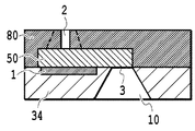
By referring to Fig. 2, the substrate 34 forms liquid flow passages 7 and bubble releasing chambers 5 together with the flow passage forming portion 4 and the ejection opening plate 8. The bubble releasing chamber 5 is provided on the thermoelectric conversion element 1 and the liquid flow passage 7 is formed to lead ink introduced via the ink supply port 3 from the ink supply chamber 10 to the bubble releasing chamber 5. The ejection opening 2 provided to penetrate through the ejection opening plate 8 is a tubular opening for establishing communication between the bubble releasing chamber 5 and an outside. When the energy is applied to the ink accommodated in the bubble releasing chamber 5 from the thermoelectric conversion element 1, ink drops are ejected from the ejection opening 2.
In the present embodiment, a silicon substrate is used as the substrate 34, but a material of the substrate 34 is not particularly limited as long as the substrate 34 can function as a support body of ejection energy generating means (thermoelectric conversion element 1), a material layer (flow passage forming portion 4) forming the liquid flow passage, and the like. In the present embodiment, the ejection opening plate 8 and the flow passage forming portion 4 are made of the same material, but the similar effect can be obtained even if made of different materials. In addition, the thermoelectric conversion element (heater) is used as the energy generating element used for ejecting liquid drops, but, not limited thereto, an element capable of controlling ejection of liquid drops by an electrical signal, such as a piezo element, may be used.
(First Embodiment)
A first embodiment in the present invention will be shown as follows.
A first embodiment in the present invention will be shown as follows.



In the present embodiment, the outer surface of the ejection opening plate 8 corresponding to the upper surface of the ejection opening 2 is recessed in a concave shape, but since this recess is extremely small, an influence of the recess on ejection performance of the ejection opening can be ignored. The recess in the concave shape is formed in relation to a manufacturing method of the print head to be described later, and is not a necessary element in view of the effect in the present invention.
(Ejection Stability at Printing Start)
Tests in regard to the ejection stability of the ejection opening in the print head in the present embodiment at a printing start were made.
Tests in regard to the ejection stability of the ejection opening in the print head in the present embodiment at a printing start were made.
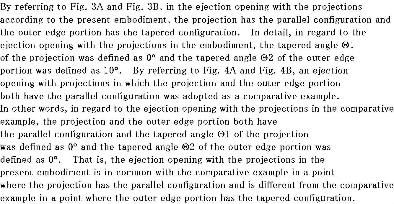
Table 1 relates to evaluations of ejection stability at a printing start and shows a result where printing starts immediately after a predetermined printing stop time elapses, to measure whether or not ink is ejected normally. The used inks were three colors of cyan, magenta, and yellow. For easy determination of a difference in performance of the ejection openings, the ink difficult in the ejection stability at the printing start was adopted. In table 1, a mark A indicates normal ejection, a mark B indicates non-ejection, and a mark C indicates deviation occurrence in the ejection direction.



From the result of the tests, it was found out that the ejection opening with the projections in the print head according to the present embodiment could normally eject even if the printing stop time became long and had excellent ejection stability at the printing start.
(Reduction Performance on Satellites and Mists)
The reduction performance on satellites and mists in the ejection opening in the print head according to the present embodiment was studied. Factors of the generation of the satellite and mist include an ink tail phenomenon of liquid drops at ejection, and there is a tendency that as the ink tail is the longer, the satellite and mist tend to be easily generated. Therefore the evaluation by simulation of the ejection process was made in view of a length of the ink tail of the liquid drop as an index of the satellite and mist reduction performance.
The reduction performance on satellites and mists in the ejection opening in the print head according to the present embodiment was studied. Factors of the generation of the satellite and mist include an ink tail phenomenon of liquid drops at ejection, and there is a tendency that as the ink tail is the longer, the satellite and mist tend to be easily generated. Therefore the evaluation by simulation of the ejection process was made in view of a length of the ink tail of the liquid drop as an index of the satellite and mist reduction performance.

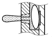
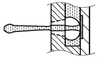
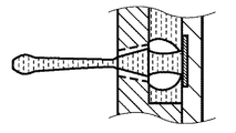
By referring to Fig. 5A to Fig. 5G, the simulation result in the present embodiment will be explained. Fig. 5A shows a state of the ejection opening in a steady state. When the heater (thermoelectric conversion element 1) is operated, an air bubble is generated and inflated in the bubble releasing chamber 5, thereby ejecting a liquid drop from the ejection opening 2 in the upper part of the bubble releasing chamber 5. Here, Fig. 5B shows a bubble releasing and air-bubble inflating process, and Fig. 5C shows the maximum bubble releasing process. Next, Fig. 5D shows a deforming process, wherein the air bubble is gradually contracted. When the liquid to be ejected starts with separation from the liquid in the ejection opening, the meniscus is generated in the ejection opening. In the process shown in Fig. 5E, the liquid forming the meniscus is pulled in the heater direction, and the liquid drops in the peripheral portion (including the outer edge portion) other than between the projections earlier than between the projections. From the process shown in Fig. 5E over the process shown in Fig. 5F, the connection between the liquid forming the meniscus between the projections and the liquid which has dropped earlier is gradually thin, and further, when the process goes to the process shown in Fig. 5G, the liquid to be ejected is completely separated from the liquid forming the meniscus in the ejection opening and the liquid remains between the projections only.
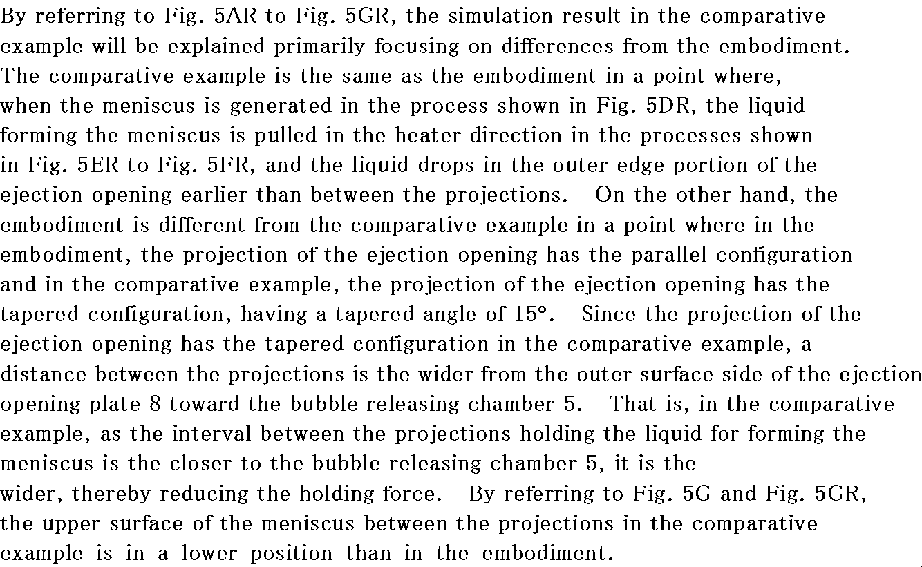

Therefore, according to the ejection opening of the print head in the present embodiment, the length of the ink tail in the liquid to be ejected can be shorter, thus providing the print head having more excellent performance on a reduction of the satellite and mist generated from the ink tail portion.


According to the print head in the present invention provided with the ejection opening with the projections having the projection and the outer edge portion described above, both of the ejection stability at the printing start and the reduction performance on the satellite and mist can be achieved in a balanced manner.
(Manufacturing Method of Print Head in First Embodiment)
A method of forming the ejection opening of the print head according to the first embodiment will be explained with reference to Fig. 6A to Fig. 6H.
A method of forming the ejection opening of the print head according to the first embodiment will be explained with reference to Fig. 6A to Fig. 6H.
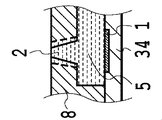
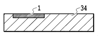
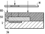
In the process shown in Fig. 6A, the substrate 34 is first provided, and thermoelectric conversion element 1 generating energy for ejecting ink is arranged on the substrate 34. In the process shown in Fig. 6B, a photopolymer is coated on the substrate 34 on which the thermoelectric conversion element 1 is arranged to form a first photopolymer layer 50 which is a mold of the bubble releasing chamber 5 and the liquid flow passage 7, and the photopolymer layer 50 is exposed and developed to pattern the bubble releasing chamber 5 and the liquid flow passage 7. Next, in the process shown in Fig. 6C, the photopolymer is coated to cover the pattern of the bubble releasing chamber 5 and the liquid flow passage 7 to form a second photopolymer layer 80 which is designed to form the flow passage forming portion 4 and the ejection opening plate 8 in Fig. 1 integrally.
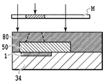
Here, in the process shown in Fig. 6D, for forming a recess in a concave shape (hereinafter, called a concave portion) on the second photopolymer layer, the second photopolymer layer is exposed via a mask M in such a manner that the concave portion becomes a non-exposure portion. Removing the mask, in the process shown in Fig. 6E, thermal treatment (Post Exposure Bake) is executed in a temperature equal to or more than a softening point of the resin in the second photopolymer layer. In consequence, the resin of the second photopolymer layer in the exposure portion exposed in the previous process is solidified and contracted. The resin of the second photopolymer layer in the non-exposure portion is heated to the softening point or more for softening, and, caused by the solidification and the contraction of the resin in the aforementioned exposure portion, the concave portion equivalent to the contracted volume is formed.
In the process shown in Fig. 6F, the ejection opening with the projections is patterned by being exposed and developed in the concave portion formed in the previous process to produce the ejection opening in the concave portion. Here, at the exposure, in the interface between air and the concave portion, the concave configuration of the concave portion functions as lens due to a difference of a refractive index of light therebetween for incident light to be refracted (refer to Fig. 7). The refraction angle is determined by an inclination angle of the concave portion. As shown in Fig. 7, the outer edge portion of the ejection opening is tapered by large refraction of light, and since part of the projection has small refraction, it is not tapered or almost not tapered.
Afterwards, in the process shown in Fig. 6G, anisotropic etching using a difference of an etching speed by a crystal orientation of silicon is used to form the ink supply chamber 10 and the ink supply opening 3 from the back side of the substrate 34, that is, from the reverse side of the bubble releasing chamber and the liquid flow passage forming surface. Finally in the process shown in Fig. 6H, the first photopolymer 50 is melted by a solvent, and the melted portion forms part of the liquid flow passage 7 and the bubble releasing chamber 5. In this manner, the print head according to the present embodiment is manufactured.
In the method of manufacturing the print head according to the present embodiment, since a focus position at exposure for forming the ejection opening 2 is in the surface vicinity of the ejection opening 2, it is possible to form the ejection opening with high dimension accuracy.
A diameter of the configuration of the concave portion can be changed by the mask, and a depth of the concave portion can be controlled by the exposure amount, and a temperature and a time of the thermal treatment. Therefore these factors can be adjusted as needed to correspond to a dimension of the ejection opening with the projections to be formed.
(Second Embodiment)
Next, a second embodiment in the present invention will be explained with reference to Fig. 8A to Fig. 8G. The second embodiment shows different forming means of the ejection opening in the print head of the first embodiment, and has the same construction as that in the first embodiment in the other points. Therefore hereinafter, only the forming means of the ejection opening will be explained and the overlapped explanation is omitted.
Next, a second embodiment in the present invention will be explained with reference to Fig. 8A to Fig. 8G. The second embodiment shows different forming means of the ejection opening in the print head of the first embodiment, and has the same construction as that in the first embodiment in the other points. Therefore hereinafter, only the forming means of the ejection opening will be explained and the overlapped explanation is omitted.
(Method of Manufacturing Print Head according to Second Embodiment)
In the forming method of the ejection opening of the print head in the second embodiment shown in Fig. 8A and Fig. 8G, since the processes shown in Fig. 8A to Fig. 8C are the same as the processes from Fig. 6A to Fig. 6C in the forming method of the ejection opening of the print head in the first embodiment shown in Fig. 6A and Fig. 6H and the subsequent processes are different, an explanation will start with the process shown in Fig. 8D.
In the forming method of the ejection opening of the print head in the second embodiment shown in Fig. 8A and Fig. 8G, since the processes shown in Fig. 8A to Fig. 8C are the same as the processes from Fig. 6A to Fig. 6C in the forming method of the ejection opening of the print head in the first embodiment shown in Fig. 6A and Fig. 6H and the subsequent processes are different, an explanation will start with the process shown in Fig. 8D.
In the forming method of the ejection opening of the print head in the second embodiment, the exposure of the outer edge portion and the exposure of the projection in the ejection opening with the projections are respectively made separately. First, in the process shown in Fig. 8D, the first exposure is made to the second photopolymer layer 80 to form the outer edge portion in the ejection opening. By shifting the focus (imaging position) to the heater side at the exposure, light incomes inside of the contour of the mask pattern on the outer surface side of the second photopolymer layer. That is, the same configuration as the mask pattern is projected in the imaging position in the heater side, and the light incomes inside of the mask pattern as being away from the imaging position. Therefore an image as the side wall of the ejection opening spreads from the outer surface side of the second photopolymer layer toward the imaging position, thereby to form the tapered configuration. In this manner, only the outer edge portion of the ejection opening with the projections is formed in a tapered configuration by the first exposure. Afterwards, in the process shown in Fig. 8E, the second exposure is made to form the projection. In the second exposure, the focus is adjusted to be imaged in the outer surface side of the second photopolymer layer for the part of the projection not to be tapered for exposure. The processes in Fig. 8F and Fig. 8G after forming the ejection opening with the projections by the exposure and the development in this manner are the same as those shown in Fig. 6G and Fig. 6H in the first embodiment.
As described above, since the outer edge portion of the ejection opening with the projections has the tapered configuration and the projection has the parallel configuration, the print head provided with the ejection opening excellent in both of the ejection stability at a printing start and the reduction performance of the satellite and the mist can be achieved.
(Third Embodiment)
Fig. 9 is a schematic perspective view showing one construction example of an inkjet printing apparatus according to a third embodiment. The inkjet printing apparatus according to the third embodiment uses the print head having the same construction as that of the first embodiment as one example of the print head according to the present invention. Therefore an overlapped explanation will be hereinafter omitted.
Fig. 9 is a schematic perspective view showing one construction example of an inkjet printing apparatus according to a third embodiment. The inkjet printing apparatus according to the third embodiment uses the print head having the same construction as that of the first embodiment as one example of the print head according to the present invention. Therefore an overlapped explanation will be hereinafter omitted.
A conveyance roller 103 rotates together with an auxiliary roller 104 while having a print medium (print sheet) 107 therebetween, and conveys and holds the print medium 107. A carriage 106 can mount the ink tanks 205 and 208 and the print heads 201 to 204, and reciprocally moves along the X direction while mounting the print heads and the ink tanks thereon. Ink is ejected from the print head during the reciprocal movement of the carriage 106, thereby printing an image on the print medium. At a non-printing operation such as at a recovery operation of the print heads 201 to 204, the carriage 106 is controlled to wait in the home position h shown in a dotted line in the figure.
The print heads 201 to 204 waiting in the home position h shown in Fig. 1, when a printing start command is inputted thereto, move together with the carriage 106 in the X direction in the figure and eject ink to print an image on the print medium 107. The printing is performed onto a region having a width corresponding to an arrangement range of the ejection openings in the print head 201 by one time movement (scan) of the print head. When the printing by one time scan of the carriage 106 in the main scan direction (X direction) is completed, the carriage 106 returns back to the home position h, wherein the printing is performed by the print heads 201 to 204 while again scanning in the X direction in the figure. Before start of a subsequent printing scan following completion of the previous printing scan, the conveyance roller 103 rotates to convey the printing medium in the sub scan direction (Y direction) intersecting with the main scan direction. By thus repeating the printing scan of the print head and the conveyance of the print medium, the printing of the image on a predetermined region of the print medium 107 is completed. The printing operation for ejecting ink from the print heads 201 to 204 is performed based upon control by control means to be described later.
In the above example, the printing operation is performed only when the print head scans in the forward direction, that is, a case of performing so-called one-way printing is explained. However, the present invention can be applied to a print head of performing so-called bidirectional printing in which the print head performs printing at both scans in the forward and backward directions. The above example shows the structure that the ink tanks 205 to 208 and the print heads 201 to 204 are mounted in the carriage 106 to be separable. However, there may be adopted the structure of mounting on a carriage a cartridge where the ink tanks 205 to 208 and the print heads 201 and 204 are formed integrally. Further, there may be adopted the structure of mounting on a carriage an integral print head of plural colors capable of ejecting inks of plural colors from one print head.
The inkjet printing apparatus according to the present embodiment is explained as a so-called serial type of inkjet printing apparatus for performing printing while the print head scans in the main scan direction (X direction). However, the print head used in the inkjet apparatus according to the present invention may be a full line type of print head for printing without scanning in the main scan direction. At this time, the print head to be used may be a single print head having a length corresponding to that of the print medium in the width direction or may be a combination of plural print heads.
(Other Embodiment)
The print head according to the above embodiment is explained as the structure of using the ejection opening having two opposing projections each formed to be convex in the inside direction in a cross section perpendicular to the ejection direction of the liquid and having the parallel configuration in the ejection direction of the liquid and the outer edge portion having the tapered configuration in the ejection direction of the liquid. However, the ejection opening applicable to the print head according to the present invention is not limited thereto. The projection is only required to be capable of forming the meniscus of the liquid in the ejection opening at the time of ejecting the liquid from the ejection opening, and may be three or more projections. For obtaining more excellent effects of the present invention, the positions of the projections are preferably provided equally in the inner periphery of the ejection opening. In a case where the number of the projections is an even number, the positions of the projections are preferably symmetrical in the inner periphery of the ejection opening.
The print head according to the above embodiment is explained as the structure of using the ejection opening having two opposing projections each formed to be convex in the inside direction in a cross section perpendicular to the ejection direction of the liquid and having the parallel configuration in the ejection direction of the liquid and the outer edge portion having the tapered configuration in the ejection direction of the liquid. However, the ejection opening applicable to the print head according to the present invention is not limited thereto. The projection is only required to be capable of forming the meniscus of the liquid in the ejection opening at the time of ejecting the liquid from the ejection opening, and may be three or more projections. For obtaining more excellent effects of the present invention, the positions of the projections are preferably provided equally in the inner periphery of the ejection opening. In a case where the number of the projections is an even number, the positions of the projections are preferably symmetrical in the inner periphery of the ejection opening.
While the present invention has been described with reference to exemplary embodiments, it is to be understood that the invention is not limited to the disclosed exemplary embodiments. The scope of the following claims is to be accorded the broadest interpretation so as to encompass all such modifications and equivalent structures and functions.
This application claims the benefit of Japanese Patent Application No. 2011-131155, filed June 13, 2011, which is hereby incorporated by reference herein in its entirety.
Claims (10)
-

- A method of manufacturing a print head according to claim 1, comprising:
a step for providing a substrate in which the energy generating element, a first photopolymer layer patterned in the configuration of the chamber to cover the energy generating element, and a second photopolymer layer to cover the first photopolymer layer are arranged in that order;
a step for exposing the second photopolymer layer via a mask for providing a non-exposure portion;
a step for executing heat treatment at a temperature equal to or more than a softening point of resin in the second photopolymer layer to form a concave portion in the non-exposure portion;
a step for exposing and developing the concave portion to pattern the ejection opening; and
a step for melting the first photopolymer layer by a solvent to form the chamber. - A method according to claim 2,
wherein in the step for exposing the second photopolymer layer,
an imaging position at the exposure time is in the vicinity of the energy generating element. - A method of manufacturing a print head according to claim 1, comprising:
a step for providing a substrate in which the energy generating element, a first photopolymer layer patterned in the configuration of chambers to cover the energy generating elements, and a second photopolymer layer to cover the first photopolymer layer are arranged in that order;
a step for exposing and developing the second photopolymer layer to form an outer edge portion of an ejection opening;
a step for exposing and developing the second photopolymer layer to form projections of the ejection opening; and
a step for melting the first photopolymer layer by a solvent to form the chamber. - A method according to claim 4,
wherein in the step for forming the projections of the ejection opening,
an imaging position at the exposure time is in an outer surface side of the second photopolymer layer. - An inkjet printing apparatus using a print head according to claim 1.
-

- A liquid ejecting head according to claim 7,
wherein in a cross section in a direction perpendicular to a direction of ejecting the liquid, the ejection opening has a cross-sectional area in an end portion closer to the outside smaller than a cross-sectional area in an end portion closer to the chamber. -

- A liquid ejecting head according to claim 7,
wherein the projection comprises two projections projecting in directions opposing with each other.
Priority Applications (2)
| Application Number | Priority Date | Filing Date | Title |
|---|---|---|---|
| US14/115,968 US8936350B2 (en) | 2011-06-13 | 2012-05-31 | Print head and inkjet printing apparatus |
| CN201280028443.0A CN103596765B (en) | 2011-06-13 | 2012-05-31 | Printhead and manufacture method, inkjet-printing device and jet head liquid |
Applications Claiming Priority (2)
| Application Number | Priority Date | Filing Date | Title |
|---|---|---|---|
| JP2011131155A JP5804787B2 (en) | 2011-06-13 | 2011-06-13 | Recording head and ink jet recording apparatus |
| JP2011-131155 | 2011-06-13 |
Publications (1)
| Publication Number | Publication Date |
|---|---|
| WO2012172744A1 true WO2012172744A1 (en) | 2012-12-20 |
Family
ID=47356757
Family Applications (1)
| Application Number | Title | Priority Date | Filing Date |
|---|---|---|---|
| PCT/JP2012/003621 Ceased WO2012172744A1 (en) | 2011-06-13 | 2012-05-31 | Print head and inkjet printing apparatus |
Country Status (4)
| Country | Link |
|---|---|
| US (1) | US8936350B2 (en) |
| JP (1) | JP5804787B2 (en) |
| CN (1) | CN103596765B (en) |
| WO (1) | WO2012172744A1 (en) |
Families Citing this family (6)
| Publication number | Priority date | Publication date | Assignee | Title |
|---|---|---|---|---|
| JP6180143B2 (en) * | 2013-03-22 | 2017-08-16 | キヤノン株式会社 | Method for manufacturing liquid discharge head |
| US10195848B2 (en) | 2016-01-08 | 2019-02-05 | Canon Kabushiki Kaisha | Liquid discharge head and liquid discharge method |
| JP6877970B2 (en) * | 2016-01-08 | 2021-05-26 | キヤノン株式会社 | Liquid discharge head and liquid discharge method |
| JP6818436B2 (en) * | 2016-05-27 | 2021-01-20 | キヤノン株式会社 | Recording element substrate, liquid discharge head and liquid discharge device |
| JP2018199235A (en) | 2017-05-26 | 2018-12-20 | キヤノン株式会社 | Liquid discharge head |
| JP2018202805A (en) * | 2017-06-08 | 2018-12-27 | キヤノン株式会社 | Liquid discharge head and manufacturing method of the same, and printing apparatus |
Citations (4)
| Publication number | Priority date | Publication date | Assignee | Title |
|---|---|---|---|---|
| JP2006082478A (en) * | 2004-09-17 | 2006-03-30 | Fuji Xerox Co Ltd | Liquid drop ejecting head, method for driving liquid drop ejecting head and liquid drop ejecting device |
| JP2008119955A (en) * | 2006-11-13 | 2008-05-29 | Canon Inc | Ink jet recording head and method of manufacturing the head |
| EP1995069A1 (en) * | 2007-05-25 | 2008-11-26 | Canon Kabushiki Kaisha | Liquid ejecting head and ink jet printing apparatus |
| US20080291245A1 (en) * | 2007-05-25 | 2008-11-27 | Canon Kabushiki Kaisha | Liquid ejection head |
Family Cites Families (7)
| Publication number | Priority date | Publication date | Assignee | Title |
|---|---|---|---|---|
| US6123413A (en) | 1995-10-25 | 2000-09-26 | Hewlett-Packard Company | Reduced spray inkjet printhead orifice |
| JP4632421B2 (en) | 2004-12-07 | 2011-02-16 | キヤノン株式会社 | Inkjet recording head |
| US7364268B2 (en) * | 2005-09-30 | 2008-04-29 | Lexmark International, Inc. | Nozzle members, compositions and methods for micro-fluid ejection heads |
| JP4818276B2 (en) | 2005-11-29 | 2011-11-16 | キヤノン株式会社 | Liquid ejection method, liquid ejection head, and liquid ejection apparatus |
| JP5393082B2 (en) | 2008-08-29 | 2014-01-22 | キヤノン株式会社 | Liquid discharge head |
| KR101518733B1 (en) * | 2008-11-27 | 2015-05-11 | 삼성전자주식회사 | Nozzle plate and method of manufacturing the same |
| JP2011073245A (en) * | 2009-09-30 | 2011-04-14 | Seiko Epson Corp | Liquid ejecting head and liquid ejecting apparatus |
-
2011
- 2011-06-13 JP JP2011131155A patent/JP5804787B2/en active Active
-
2012
- 2012-05-31 CN CN201280028443.0A patent/CN103596765B/en active Active
- 2012-05-31 WO PCT/JP2012/003621 patent/WO2012172744A1/en not_active Ceased
- 2012-05-31 US US14/115,968 patent/US8936350B2/en active Active
Patent Citations (4)
| Publication number | Priority date | Publication date | Assignee | Title |
|---|---|---|---|---|
| JP2006082478A (en) * | 2004-09-17 | 2006-03-30 | Fuji Xerox Co Ltd | Liquid drop ejecting head, method for driving liquid drop ejecting head and liquid drop ejecting device |
| JP2008119955A (en) * | 2006-11-13 | 2008-05-29 | Canon Inc | Ink jet recording head and method of manufacturing the head |
| EP1995069A1 (en) * | 2007-05-25 | 2008-11-26 | Canon Kabushiki Kaisha | Liquid ejecting head and ink jet printing apparatus |
| US20080291245A1 (en) * | 2007-05-25 | 2008-11-27 | Canon Kabushiki Kaisha | Liquid ejection head |
Also Published As
| Publication number | Publication date |
|---|---|
| JP2013000914A (en) | 2013-01-07 |
| US20140125735A1 (en) | 2014-05-08 |
| JP5804787B2 (en) | 2015-11-04 |
| CN103596765A (en) | 2014-02-19 |
| US8936350B2 (en) | 2015-01-20 |
| CN103596765B (en) | 2015-09-02 |
Similar Documents
| Publication | Publication Date | Title |
|---|---|---|
| JP3675272B2 (en) | Liquid discharge head and method for manufacturing the same | |
| WO2012172744A1 (en) | Print head and inkjet printing apparatus | |
| EP2046582B1 (en) | Fluid ejection devices and methods of fabrication | |
| CN100425447C (en) | Liquid ejection head, liquid ejection apparatus, and method for fabricating liquid ejection head | |
| KR100499298B1 (en) | Liquid discharge head and method for manufacturing such head | |
| WO2011058719A1 (en) | Method for manufacturing liquid ejection head | |
| JP4614383B2 (en) | Inkjet recording head manufacturing method and inkjet recording head | |
| US8210655B2 (en) | Liquid ejection head and manufacturing method of liquid ejection head | |
| KR20030019272A (en) | Liquid ejection head and image-forming apparatus using the same | |
| US20120218350A1 (en) | Liquid ejection head and process for producing the same | |
| JP2004042397A (en) | Liquid ejection head and method of manufacturing the head | |
| US20070247493A1 (en) | Printing head, ink jet printing apparatus, and ink jet printing method | |
| JP2008119955A (en) | Ink jet recording head and method of manufacturing the head | |
| CN101638003B (en) | Droplet discharge head and droplet discharging unit incorporating the same | |
| JP4455943B2 (en) | Droplet discharge head, liquid cartridge, droplet discharge device, recording device | |
| JP3907686B2 (en) | Liquid discharge head | |
| KR101106325B1 (en) | Liquid discharge head, liquid discharge head manufacturing method and structure formation method | |
| US10406813B2 (en) | Liquid ejection head | |
| JP2007216415A (en) | Liquid jet recording head and manufacturing method thereof | |
| EP3212414B1 (en) | Ink jet printhead | |
| JP2014040023A (en) | Recording method |
Legal Events
| Date | Code | Title | Description |
|---|---|---|---|
| 121 | Ep: the epo has been informed by wipo that ep was designated in this application |
Ref document number: 12801371 Country of ref document: EP Kind code of ref document: A1 |
|
| WWE | Wipo information: entry into national phase |
Ref document number: 14115968 Country of ref document: US |
|
| NENP | Non-entry into the national phase |
Ref country code: DE |
|
| 122 | Ep: pct application non-entry in european phase |
Ref document number: 12801371 Country of ref document: EP Kind code of ref document: A1 |