WO2012169455A1 - Seat sliding device - Google Patents
Seat sliding device Download PDFInfo
- Publication number
- WO2012169455A1 WO2012169455A1 PCT/JP2012/064358 JP2012064358W WO2012169455A1 WO 2012169455 A1 WO2012169455 A1 WO 2012169455A1 JP 2012064358 W JP2012064358 W JP 2012064358W WO 2012169455 A1 WO2012169455 A1 WO 2012169455A1
- Authority
- WO
- WIPO (PCT)
- Prior art keywords
- rail
- rattling
- rail member
- seat
- rollers
- Prior art date
Links
Images


Classifications
-
- B—PERFORMING OPERATIONS; TRANSPORTING
- B60—VEHICLES IN GENERAL
- B60N—SEATS SPECIALLY ADAPTED FOR VEHICLES; VEHICLE PASSENGER ACCOMMODATION NOT OTHERWISE PROVIDED FOR
- B60N2/00—Seats specially adapted for vehicles; Arrangement or mounting of seats in vehicles
- B60N2/02—Seats specially adapted for vehicles; Arrangement or mounting of seats in vehicles the seat or part thereof being movable, e.g. adjustable
- B60N2/04—Seats specially adapted for vehicles; Arrangement or mounting of seats in vehicles the seat or part thereof being movable, e.g. adjustable the whole seat being movable
- B60N2/06—Seats specially adapted for vehicles; Arrangement or mounting of seats in vehicles the seat or part thereof being movable, e.g. adjustable the whole seat being movable slidable
- B60N2/07—Slide construction
- B60N2/0702—Slide construction characterised by its cross-section
- B60N2/0705—Slide construction characterised by its cross-section omega-shaped
-
- B—PERFORMING OPERATIONS; TRANSPORTING
- B60—VEHICLES IN GENERAL
- B60N—SEATS SPECIALLY ADAPTED FOR VEHICLES; VEHICLE PASSENGER ACCOMMODATION NOT OTHERWISE PROVIDED FOR
- B60N2/00—Seats specially adapted for vehicles; Arrangement or mounting of seats in vehicles
- B60N2/02—Seats specially adapted for vehicles; Arrangement or mounting of seats in vehicles the seat or part thereof being movable, e.g. adjustable
- B60N2/04—Seats specially adapted for vehicles; Arrangement or mounting of seats in vehicles the seat or part thereof being movable, e.g. adjustable the whole seat being movable
- B60N2/06—Seats specially adapted for vehicles; Arrangement or mounting of seats in vehicles the seat or part thereof being movable, e.g. adjustable the whole seat being movable slidable
- B60N2/07—Slide construction
- B60N2/0702—Slide construction characterised by its cross-section
- B60N2/0715—C or U-shaped
-
- B—PERFORMING OPERATIONS; TRANSPORTING
- B60—VEHICLES IN GENERAL
- B60N—SEATS SPECIALLY ADAPTED FOR VEHICLES; VEHICLE PASSENGER ACCOMMODATION NOT OTHERWISE PROVIDED FOR
- B60N2/00—Seats specially adapted for vehicles; Arrangement or mounting of seats in vehicles
- B60N2/02—Seats specially adapted for vehicles; Arrangement or mounting of seats in vehicles the seat or part thereof being movable, e.g. adjustable
- B60N2/04—Seats specially adapted for vehicles; Arrangement or mounting of seats in vehicles the seat or part thereof being movable, e.g. adjustable the whole seat being movable
- B60N2/06—Seats specially adapted for vehicles; Arrangement or mounting of seats in vehicles the seat or part thereof being movable, e.g. adjustable the whole seat being movable slidable
- B60N2/07—Slide construction
- B60N2/0722—Constructive details
Definitions
- the present invention relates to a seat slide apparatus for guiding slide movement of a sheet.
- a vehicle seat is attached to a vehicle body via a seat slide device that adjusts its position in the longitudinal direction of the vehicle.
- the seat slide device slides a seat along a pair of rails, and rolls a plurality of rollers provided along the rails to adjust the position of the seat in the vehicle longitudinal direction.
- a roller structure of a sheet slide apparatus application of the technique of patent document 1, 2 is examined, for example.
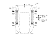
- FIG. 9 shows a conventional general seat slide device 81.
- the seat slide device 81 has a pair of rail units 82, 82 on both sides in the seat width direction.
- Each rail unit 82, 82 comprises a lower rail 83 attached to the floor in the vehicle and an upper rail 84 attached to the back of the seat 85.
- a plurality of rollers 86 are interposed between the lower rail 83 and the upper rail 84.
- the rollers 86 are double-supported type having a pair of wheels on both sides in the seat width direction, and are disposed at two locations in the rail longitudinal direction (vehicle longitudinal direction) of each rail unit 82. That is, regarding the rollers 86, a total of four wheels are provided in each of the rail units 82, 82, that is, a total of eight wheels in the entire seat 85.
- the seat slide device 81 of FIG. 9 requires a total of eight wheels as the roller 86, so the number of wheels is too large, and the sliding resistance when moving the sheet 85 is increased. There's a problem. However, simply reducing the number of wheels may lead to the problem of rattling the seat, so there is a need for development of technology that can achieve both reduction in the number of wheels on the roller and prevention of rattling of the seat.
- An object of the present invention is to provide a seat slide device capable of reducing the number of roller wheels and making it possible to prevent occurrence of rattling of a sheet.
- a plurality of rail units provided between a sheet and a sheet mounting surface, wherein each rail unit is attached to the sheet mounting surface.
- a plurality of rail units including a rail member and a second rail member attached to the seat, wherein the position of the seat can be adjusted by sliding the second rail member relative to the first rail member;
- a plurality of rollers disposed between the first rail member and the second rail member, and three rollers are provided for each of the rail units, and the first rail is provided by the three rollers
- a seat slide device is provided, wherein the member supports the second rail member at three points.
- the first rail member supports the second rail member at three points by three rollers. Therefore, even if a deviation occurs in the height direction between the first rail member and the second rail member, this deviation can be effectively absorbed by the three-point support of the roller. . Therefore, it is possible to reduce the number of wheels of the roller, and it is also possible to make the sheet less likely to rattle.
- the number of wheels of the roller can be reduced, and the rattling of the sheet can be made less likely to occur.
- FIG. 2 is a plan view showing the seat slide device of FIG. 1; The disassembled perspective view which shows a rail unit. Sectional drawing which shows the roller part of a rail unit. Sectional drawing which shows the shoe
- A) is a perspective view which shows one side of a shoe
- (b) is a perspective view which shows the other side of a shoe.
- (A) And (b) is a top view which shows the seat slide apparatus of another example. The top view of the seat slide apparatus of other another example. The top view which shows the conventional seat slide apparatus.
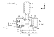
- the seat 1 installed in the vehicle is attached to the in-vehicle floor 3 via a seat slide device 2 that slides the seat 1 in the vehicle longitudinal direction (X-axis direction in FIG. 1). There is.
- the seat slide device 2 can set the position of the seat 1 in the vehicle longitudinal direction in multiple stages.
- the in-vehicle floor 3 corresponds to a seat attachment surface.
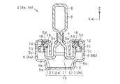
- the seat slide device 2 has a pair of elongated rail units 4, 4 on both sides in the sheet width direction (Y-axis direction in FIG. 2). Therefore, the seat 1 is supported on the floor 3 by the pair of rail units 4 arranged in the seat width direction.
- the pair of rail units 4 is a left side rail unit 4a located on the left side in the figure and a right side rail unit 4b located on the right side in the figure. Further, the left side rail unit 4 a and the right side rail unit 4 b are arranged to be symmetrical with respect to the center line in the width direction of the seat 1.
- the lower rail 5 attached to the in-vehicle floor 3 and the upper rail 6 attached to the back surface of the seat 1 are provided slidably.
- the lower rail 5 functions as a support rail for the upper rail 6 and thus is formed longer than the upper rail 6.
- the lower rail 5 and the upper rail 6 constitute a first rail member and a second rail member.
- grooves 7 are formed in a band along the longitudinal direction of the lower rail 5 (the X-axis direction in FIG. 3). Further, as shown in FIG. 4 and FIG. 5, a pair of space portions 8 communicating with the groove 7 is provided in the lower rail 5.
- the pair of spaces 8 is formed on both sides of the groove 7 in the sheet width direction (the Y-axis direction in FIGS. 4 and 5) with the groove 7 in the middle.
- the space portions 8 and 8 are indicated by 8a at the outer side in the sheet width direction, that is, on the left side in the drawing, and by 8b in the sheet width direction, that is, on the right side in the drawing.
- the lower rail 5 is formed by bending one steel material (iron plate).
- the upper rail 6 has a hollow main body portion 9 that abuts and supports the seat 1 and an extending portion 10 formed in a bifurcated shape from the main body portion 9 downward.
- the extending portion 10 includes a bifurcated portion 11 at the base of two stacked plate members and a pair of bent portions 12 and 12 bent upward from the tip of the bifurcated portion 11.
- the bent portions 12 have a substantially L-shaped cross section and are disposed symmetrically with respect to the center line of the upper rail 6 in the sheet width direction (the Y-axis direction in FIGS. 4 and 5).
- the pair of bent portions 12 and 12 is indicated by 12a located on the outer side in the sheet width direction, that is, on the left side of the sheet, and 12b in the sheet width direction, that is, located on the right side.
- the forked portion 11 is passed through the groove 7 of the lower rail 5, and the bent portions 12 a and 12 b are accommodated in the space portions 8 a and 8 b of the lower rail 5.
- Upper rail 6 slides relative to lower rail 5 along groove 7 along the longitudinal direction of the vehicle. The sliding position of the lower rail 5 and the upper rail 6, that is, the position of the seat 1 in the vehicle longitudinal direction is held by a lock mechanism (not shown) provided between the lower rail 5 and the upper rail 6.
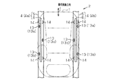
- rollers 13 for guiding the slide movement of the rails 5 and 6 are attached at a plurality of places.
- the rollers 13, 13... are rotatably supported on the side wall surfaces of the outer bent portion 12a and the inner bent portion 12b in each of the upper rails 6, 6 (only one is shown in FIG. 3).
- roller 13 in one upper rail 6, a roller structure in which the upper rail 6 is supported at three points with respect to the lower rail 5 is adopted.
- the roller structure is a cantilever type having wheels at only one of the pair of bent portions 12a and 12b at one roller arrangement position.
- one roller 13 is disposed at each end of the outer bent portion 12a in the longitudinal direction of the upper rail 6 (longitudinal direction of rail: X-axis direction in FIG. 3). It has a three-point support structure in which one roller 13 is disposed at the center in the longitudinal direction.
- the roller structure has a structure in which the upper rail 6 is supported at three points with respect to the lower rail 5 by the rollers 13 a and 13 b at both ends of the rail unit 4 and the roller 13 c in the middle. Further, in the rollers 13, cantilever wheels are alternately arranged along the rail longitudinal direction.
- the roller 13 has three wheels when viewed by the rail unit 4 on one side, and has a total of six wheels when viewed by the entire seat 1.
- the two rollers 13a, 13b are arranged outside the seat 1 with respect to the center line in the width direction of each rail unit 4a, 4b, and one roller 13c is for each rail unit 4a, 4b. It is arranged inside the sheet 1 with respect to the center line in the width direction.
- three rollers are arranged to form an apex of an isosceles triangle.
- the roller 13 is disposed on the upper surface of the roller rolling wall 5 b at a position one step higher than the bottom wall 5 a of the lower rail 5 in the space portion 8 of the lower rail 5. Then, when the upper rail 6 slides relative to the lower rail 5, the roller 13 rolls on the upper surface of the roller rolling wall 5 b to smoothly slide the upper rail 6, that is, the position of the seat 1 with a light force. Adjustment is ensured.
- a plurality of shoes 14 that suppress the rattling between the rails 5 and 6 are provided at a plurality of locations. It is attached.
- the shoes 14 are resin pieces for suppressing backlash.
- the shoes 14, 14... Are disposed in total at four rail longitudinal end portions of the outer bent portion 12a and the inner bent portion 12b in one rail unit 4. Therefore, a total of eight shoes 14 are arranged in each of the left side rail unit 4a and the right side rail unit 4b, four each when viewed in the entire seat 1.
- the shoe 14 corresponds to a rattling suppressing member.
- the shoe 14 has an outer sliding contact 15 for absorbing rattling in the sheet width direction (Y-axis direction in FIG. 5), and a vertical direction (Z in FIG. 5) of the rail unit 4. And an upper sliding contact piece 16 for absorbing rattling.
- the outer sliding contact piece 15 is formed by hollowing the side portion of the shoe 14 and is in sliding contact with the inner surface of the outer wall 5 c of the lower rail 5.
- the upper sliding contact piece 16 is formed by hollowing the entire upper portion of the shoe 14, and can slide on the inner surface of the upper wall 5 d of the lower rail 5.
- the upper sliding contact piece 16 and the outer sliding contact piece 15 are both formed in a substantially arc shape.
- the outer sliding contact piece 15 and the upper sliding contact piece 16 are attached to stepped portions 17 (recessed portions) formed to be recessed in the tip end surfaces of the respective bent portions 12a and 12b.
- the stepped portion 17 is at a position one step lower than the tip end surfaces of the bent portions 12a and 12b.
- the outer sliding contact piece 15 and the upper sliding contact piece 16 are positioned on the upper rail 6 by engaging the mounting groove 18 formed in the self with the stepped portion 17.
- the space portion 8 is formed by a region surrounded by the bottom wall 5a, the roller rolling wall 5b, the outer wall 5c, the upper wall 5d, and the inner wall 5e.
- channel 7 says the area
- one of the wheels in the roller 13 may be multiplied by the mounting height, and the upper rail 6 may be inclined relative to the lower rail 5 in the direction of arrow A1 in FIG. Ru.
- an excessive load is applied to a specific one wheel, and the lower rail 5 and the shoe 14 are in a strong interference state, which may increase the sliding resistance when moving the seat 1. That is, when adjusting the position of the sheet 1, the operator feels the sheet 1 heavy, which makes it difficult to perform the position alignment.
- positioned at each rail unit 4a, 4b is set to three (13a, 13b, 13c).
- the seat slide device 2 has a structure in which the upper rail 6 is supported at three points with respect to the lower rail 5 by these three wheels. Therefore, the upper rail 6 can be supported on the lower rail 5 in one plane by the three-point support structure.
- the seat slide device 2 it is only necessary to provide three rollers 13 for each of the rail units 4a and 4b. That is, when viewed in the entire sheet 1, only six rollers 13 may be provided. Therefore, it is possible to suppress rattling of the seat 1 while suppressing the number of wheels mounted on the seat slide device 2 to a small number.
- each of the rail units 4a and 4b has a three-point support structure with three rollers 13, between the lower rail 5 and the upper rail 6 in units of each rail unit 4a and 4b.
- the rattling is suppressed. For this reason, the effect of securing stable slide movement of the seat 1 is enhanced. Note that rattling between the left and right rail units 4 a and 4 b is absorbed by the frame of the seat 1.
- the support of the upper rail 6 with respect to the lower rail 5 is performed by three-point support by the three cantilever rollers 13a, 13b and 13c. Therefore, even if a deviation occurs in the rail height direction between the rails 5 and 6, this deviation can be absorbed by the three-point support of the roller 13. Therefore, the number of wheels of the roller 13 can be reduced, and the looseness of the seat 1 can be reduced.
- warping deformation refers to a deformation in which the center of the lower rail 5 is lowered and the both ends are lifted.
- the shoe 14 is disposed between the two rollers 13 as in the present embodiment, the shoe 14 is effective to fill the gap caused by the rail deformation, which is effective in suppressing the rattling of the sheet 1 Becomes higher.
- the embodiment is not limited to the configuration described above, and may be changed to the following modes.
- the rollers 13a and 13b located at the end of the upper rail 6 may be disposed in the inner bent portion 12b, and the middle roller 13c may be disposed in the outer bent portion 12a.
- the two rollers 13 located at the end of the upper rail 6 are disposed inside the sheet 1 with respect to the center line in the width direction of the rail units 4a, 4b. Are disposed on the outside of the seat 1 with respect to the center line in the width direction of the rail units 4a and 4b.
- the roller 13 may be arrange
- the two rollers 13a, 13b located at the end of the upper rail 6 are arranged outside the seat 1 with respect to the center line in the width direction of each rail unit 4a, 4b.
- the two rollers 13c may be disposed inside the seat 1 with respect to the center line in the width direction of each of the rail units 4a and 4b.
- the shoe 14 is not limited to being disposed between the roller 13a (13b) located at the end of the upper rail 6 and the roller 13c in the middle. As shown in FIG. 8, the shoes 14 may be disposed outside the rollers 13 a and 13 b located at the end of the upper rail 6. That is, the shoe 14 on the front side is positioned forward of the roller 13a located on the vehicle frontmost side in the longitudinal direction of each rail unit 4a, 4b, and the shoe 14 on the rear side is in the longitudinal direction of each rail unit 4a, 4b. You may arrange
- the lower rail 5 may be attached to the seat 1 and the upper rail 6 may be attached to the in-vehicle floor 3.
- the number of rail units 4 is not limited to two, and may be, for example, three or more.
- the seat attachment surface is not limited to the in-vehicle floor 3 and may be changed to another place.
- the number of attached shoes 14 is not limited to eight in total, and can be changed as appropriate. Also, the mounting position of the shoe 14 may be changed as appropriate according to the use situation.
- the rattle suppressing member is not limited to the shoe 14, and other parts may be used.
- the arrangement position of the roller 13 is not limited to the example described in the embodiment or the other example, and can be changed to another arrangement position as long as it has a three-point support structure that can be supported on one plane.
- the seat slide device 2 is not limited to being applied to a vehicle, and can be applied to other devices and devices.
Abstract
In the present invention, a seat sliding device allows a vehicle seat to be positioned in the front-rear direction of the vehicle. This seat sliding device comprises a pair of rail units lined up in the width direction of the seat. Each of the rail units comprises a first rail member that is attached to a seat mounting surface and a second rail member that is attached to the seat. Each rail unit is provided with three rollers, and using these three rollers the second rail member is supported on the first rail member at three points.
Description
本発明は、シートのスライド移動を案内するシートスライド装置に関する。
BACKGROUND OF THE INVENTION Field of the Invention The present invention relates to a seat slide apparatus for guiding slide movement of a sheet.
従来、車両のシートは、車両前後方向において位置を調整するシートスライド装置を介して車体に取り付けられている。シートスライド装置は、シートを一対のレールに沿ってスライド可能とし、レールに沿って設けられた複数のローラを転動させてシートの車両前後方向の位置を調整するものである。シートスライド装置のローラ構造としては、例えば特許文献1,2に記載の技術の適用が検討されている。
Conventionally, a vehicle seat is attached to a vehicle body via a seat slide device that adjusts its position in the longitudinal direction of the vehicle. The seat slide device slides a seat along a pair of rails, and rolls a plurality of rollers provided along the rails to adjust the position of the seat in the vehicle longitudinal direction. As a roller structure of a sheet slide apparatus, application of the technique of patent document 1, 2 is examined, for example.
図9は、従来の一般的なシートスライド装置81を示す。シートスライド装置81は、シート幅方向の両側に一対のレールユニット82,82を有する。各レールユニット82,82は、車内フロアに取り付けられたロアレール83と、シート85の裏面に取り付けられたアッパーレール84とからなる。
FIG. 9 shows a conventional general seat slide device 81. The seat slide device 81 has a pair of rail units 82, 82 on both sides in the seat width direction. Each rail unit 82, 82 comprises a lower rail 83 attached to the floor in the vehicle and an upper rail 84 attached to the back of the seat 85.
ロアレール83とアッパーレール84との間には、複数のローラ86が介装されている。ローラ86は、シート幅方向の両側に一対の車輪を持つ両持ち式となっており、各レールユニット82のレール長手方向(車両前後方向)において2箇所に配置されている。つまり、ローラ86に関し、それぞれのレールユニット82,82に車輪が計4つずつ、つまりシート85全体で計8つの車輪が設けられている。
A plurality of rollers 86 are interposed between the lower rail 83 and the upper rail 84. The rollers 86 are double-supported type having a pair of wheels on both sides in the seat width direction, and are disposed at two locations in the rail longitudinal direction (vehicle longitudinal direction) of each rail unit 82. That is, regarding the rollers 86, a total of four wheels are provided in each of the rail units 82, 82, that is, a total of eight wheels in the entire seat 85.
ところが、図9のシートスライド装置81では、ローラ86として計8個の車輪を必要とするので、車輪の個数が多すぎるという問題や、シート85を移動させるときの摺動抵抗が大きくなってしまう問題がある。しかし、ただ単に車輪の数を削減するのでは、シートががたつく問題に繋がる可能性があるので、ローラの車輪数削減とシートがたつき防止とを両立することができる技術の開発ニーズがある。
However, the seat slide device 81 of FIG. 9 requires a total of eight wheels as the roller 86, so the number of wheels is too large, and the sliding resistance when moving the sheet 85 is increased. There's a problem. However, simply reducing the number of wheels may lead to the problem of rattling the seat, so there is a need for development of technology that can achieve both reduction in the number of wheels on the roller and prevention of rattling of the seat.
本発明の目的は、ローラの車輪数を削減することができるとともに、シートのがたつきも生じ難くすることができるシートスライド装置を提供することにある。
An object of the present invention is to provide a seat slide device capable of reducing the number of roller wheels and making it possible to prevent occurrence of rattling of a sheet.
前記問題点を解決するために、本発明の一態様では、シートとシート取り付け面との間に設けられる複数のレールユニットであって、各レールユニットが、前記シート取り付け面に取り付けられた第1レール部材と、前記シートに取り付けられた第2レール部材とを含み、前記第2レール部材が第1レール部材に対してスライドすることにより前記シートの位置を調整可能とする、複数のレールユニットと、前記第1レール部材と前記第2レール部材との間に配設された複数のローラとを備え、前記各レールユニットに対して3つローラが設けられ、当該3つのローラにより前記第1レール部材が前記第2レール部材を3点で支持する、シートスライド装置を提供する。
In order to solve the above-mentioned problems, in one aspect of the present invention, there are provided a plurality of rail units provided between a sheet and a sheet mounting surface, wherein each rail unit is attached to the sheet mounting surface. A plurality of rail units including a rail member and a second rail member attached to the seat, wherein the position of the seat can be adjusted by sliding the second rail member relative to the first rail member; A plurality of rollers disposed between the first rail member and the second rail member, and three rollers are provided for each of the rail units, and the first rail is provided by the three rollers A seat slide device is provided, wherein the member supports the second rail member at three points.
本発明の構成によれば、第1レール部材が第2レール部材を、3つのローラによる3点で支持している。そのため、仮に第1レール部材と第2レール部材との間に、高さ方向において偏差が生じる場合であっても、この偏差をローラの3点支持により、効果的に吸収することが可能となる。よって、ローラの車輪数を削減することが可能になるとともに、シートのがたつきも生じ難くすることが可能となる。
According to the configuration of the present invention, the first rail member supports the second rail member at three points by three rollers. Therefore, even if a deviation occurs in the height direction between the first rail member and the second rail member, this deviation can be effectively absorbed by the three-point support of the roller. . Therefore, it is possible to reduce the number of wheels of the roller, and it is also possible to make the sheet less likely to rattle.
本発明によれば、ローラの車輪数を削減することができるとともに、シートのがたつきも生じ難くすることができる。
According to the present invention, the number of wheels of the roller can be reduced, and the rattling of the sheet can be made less likely to occur.
以下、本発明の一実施形態に係るシートスライド装置を図1~図6に従って説明する。
Hereinafter, a seat slide device according to an embodiment of the present invention will be described with reference to FIGS.
図1及び図2に示すように、車内に設置されたシート1は、シート1を車両前後方向(図1のX軸方向)にスライドさせるシートスライド装置2を介して車内フロア3に取り付けられている。シートスライド装置2は、シート1の車両前後方向の位置を多段階に設定可能とする。なお、車内フロア3がシート取り付け面に相当する。
As shown in FIGS. 1 and 2, the seat 1 installed in the vehicle is attached to the in-vehicle floor 3 via a seat slide device 2 that slides the seat 1 in the vehicle longitudinal direction (X-axis direction in FIG. 1). There is. The seat slide device 2 can set the position of the seat 1 in the vehicle longitudinal direction in multiple stages. The in-vehicle floor 3 corresponds to a seat attachment surface.
図2に示すように、シートスライド装置2は、シート幅方向(図2のY軸方向)の両側に一対の細長いレールユニット4,4を有する。このため、シート1は、シート幅方向に並ぶ一対のレールユニット4,4にて、車内フロア3に支持されている。なお、一対のレールユニット4,4は、図中左側に位置する左側レールユニット4aと、図中右側に位置する右側レールユニット4bとする。また、左側レールユニット4aと右側レールユニット4bとは、シート1の幅方向中心線に関して対称をなすように配置されている。
As shown in FIG. 2, the seat slide device 2 has a pair of elongated rail units 4, 4 on both sides in the sheet width direction (Y-axis direction in FIG. 2). Therefore, the seat 1 is supported on the floor 3 by the pair of rail units 4 arranged in the seat width direction. The pair of rail units 4 is a left side rail unit 4a located on the left side in the figure and a right side rail unit 4b located on the right side in the figure. Further, the left side rail unit 4 a and the right side rail unit 4 b are arranged to be symmetrical with respect to the center line in the width direction of the seat 1.
図3に示すように、各レールユニット4a,4bには、車内フロア3に取り付けられたロアレール5と、シート1の裏面に取り付けられたアッパーレール6とが、互いにスライド可能に設けられている。ロアレール5は、アッパーレール6の支持レールとして機能するので、アッパーレール6よりも長く形成されている。なお、ロアレール5及びアッパーレール6が第1レール部材及び第2レール部材を構成する。
As shown in FIG. 3, in each of the rail units 4a and 4b, the lower rail 5 attached to the in-vehicle floor 3 and the upper rail 6 attached to the back surface of the seat 1 are provided slidably. The lower rail 5 functions as a support rail for the upper rail 6 and thus is formed longer than the upper rail 6. The lower rail 5 and the upper rail 6 constitute a first rail member and a second rail member.
図3~図5に示すように、ロアレール5の上面には、ロアレール5の長手方向(図3のX軸方向)に沿って一帯に溝7が形成されている。また、図4及び図5に示すように、ロアレール5の内部には、溝7と連通する一対の空間部8が設けられている。一対の空間部8は、溝7を真ん中にシート幅方向(図4及び図5のY軸方向)の両側に形成されている。空間部8,8について、シート幅方向外側、即ち紙面左側に位置するものを8aと示し、シート幅方向内側、即ち紙面右側に位置するものを8bと示す。ロアレール5は、1枚の鋼材(鉄板)を折り曲げ加工することにより形成されている。
As shown in FIGS. 3 to 5, on the upper surface of the lower rail 5, grooves 7 are formed in a band along the longitudinal direction of the lower rail 5 (the X-axis direction in FIG. 3). Further, as shown in FIG. 4 and FIG. 5, a pair of space portions 8 communicating with the groove 7 is provided in the lower rail 5. The pair of spaces 8 is formed on both sides of the groove 7 in the sheet width direction (the Y-axis direction in FIGS. 4 and 5) with the groove 7 in the middle. The space portions 8 and 8 are indicated by 8a at the outer side in the sheet width direction, that is, on the left side in the drawing, and by 8b in the sheet width direction, that is, on the right side in the drawing. The lower rail 5 is formed by bending one steel material (iron plate).
アッパーレール6は、シート1を当接して支持する中空状の本体部9と、本体部9から下方に二股状に形成された延設部10とを有する。延設部10は、2枚の板材を重ね合わせた根元の二股状部11と、この二股状部11の先端から上方に曲げ形成された一対の折り曲げ部12,12とを含む。これら折り曲げ部12,12は、断面略L字状を呈するとともに、シート幅方向(図4及び図5のY軸方向)におけるアッパーレール6の中心線に関して対称的に配置されている。一対の折り曲げ部12,12について、シート幅方向外側、即ち紙面左側に位置するものを12aと示し、シート幅方向内側、即ち紙面右側に位置するものを12bと示す。
The upper rail 6 has a hollow main body portion 9 that abuts and supports the seat 1 and an extending portion 10 formed in a bifurcated shape from the main body portion 9 downward. The extending portion 10 includes a bifurcated portion 11 at the base of two stacked plate members and a pair of bent portions 12 and 12 bent upward from the tip of the bifurcated portion 11. The bent portions 12 have a substantially L-shaped cross section and are disposed symmetrically with respect to the center line of the upper rail 6 in the sheet width direction (the Y-axis direction in FIGS. 4 and 5). The pair of bent portions 12 and 12 is indicated by 12a located on the outer side in the sheet width direction, that is, on the left side of the sheet, and 12b in the sheet width direction, that is, located on the right side.
アッパーレール6は、二股状部11がロアレール5の溝7に通されるとともに、折り曲げ部12a,12bがロアレール5のそれぞれの空間部8a,8bに収納されている。アッパーレール6は、ロアレール5に対し、溝7に沿って車両前後方向に沿ってスライドする。なお、ロアレール5とアッパーレール6とのスライド位置、つまりシート1の車両前後方向の位置は、ロアレール5及びアッパーレール6の間に設けられたロック機構(図示略)により保持される。
In the upper rail 6, the forked portion 11 is passed through the groove 7 of the lower rail 5, and the bent portions 12 a and 12 b are accommodated in the space portions 8 a and 8 b of the lower rail 5. Upper rail 6 slides relative to lower rail 5 along groove 7 along the longitudinal direction of the vehicle. The sliding position of the lower rail 5 and the upper rail 6, that is, the position of the seat 1 in the vehicle longitudinal direction is held by a lock mechanism (not shown) provided between the lower rail 5 and the upper rail 6.
図2及び図3に示すように、ロアレール5とアッパーレール6との間には、これらレール5,6のスライド移動を案内する複数のローラ13が複数箇所に取り付けられている。ローラ13,13…は、各アッパーレール6,6(図3では片方のみ図示)において、外側折り曲げ部12a及び内側折り曲げ部12bのそれぞれの側壁面に回転可能に支持されている。
As shown in FIGS. 2 and 3, between the lower rail 5 and the upper rail 6, a plurality of rollers 13 for guiding the slide movement of the rails 5 and 6 are attached at a plurality of places. The rollers 13, 13... Are rotatably supported on the side wall surfaces of the outer bent portion 12a and the inner bent portion 12b in each of the upper rails 6, 6 (only one is shown in FIG. 3).
ローラ13について、1つのアッパーレール6において、アッパーレール6をロアレール5に対して3点で支持するローラ構造が採用されている。ローラ構造は、1つのローラ配置箇所において、一対の折り曲げ部12a,12bのうち片方のみに車輪を有する片持ち式である。また、ローラ構造は、外側折り曲げ部12aにおいてアッパーレール6の長手方向(レール長手方向:図3のX軸方向)の両端にローラ13がそれぞれ1つずつ配置されるとともに、内側折り曲げ部12bにおいてレール長手方向の中央にローラ13が1つ配置された3点支持構造を有する。
With regard to the roller 13, in one upper rail 6, a roller structure in which the upper rail 6 is supported at three points with respect to the lower rail 5 is adopted. The roller structure is a cantilever type having wheels at only one of the pair of bent portions 12a and 12b at one roller arrangement position. In the roller structure, one roller 13 is disposed at each end of the outer bent portion 12a in the longitudinal direction of the upper rail 6 (longitudinal direction of rail: X-axis direction in FIG. 3). It has a three-point support structure in which one roller 13 is disposed at the center in the longitudinal direction.
このため、ローラ構造は、レールユニット4の両端部のローラ13a,13bと、真ん中のローラ13cとで、アッパーレール6をロアレール5に対して3点で支持する構造を有する。また、ローラ13は、片持ち式の車輪が、レール長手方向に沿って互い違いに配置されている。ローラ13は、片側のレールユニット4で見た場合、3つの車輪を持ち、シート1全体で見た場合、計6つの車輪を持つ。各レールユニット4a,4bについて、2つのローラ13a,13bは各レールユニット4a,4bの幅方向の中心線に対してシート1の外側に配置され、1つのローラ13cは各レールユニット4a,4bの幅方向の中心線に対してシート1の内側に配置されている。各レールユニット4a,4bにおいて、3つのローラが二等辺三角形の頂点をなすように配置されている。
Therefore, the roller structure has a structure in which the upper rail 6 is supported at three points with respect to the lower rail 5 by the rollers 13 a and 13 b at both ends of the rail unit 4 and the roller 13 c in the middle. Further, in the rollers 13, cantilever wheels are alternately arranged along the rail longitudinal direction. The roller 13 has three wheels when viewed by the rail unit 4 on one side, and has a total of six wheels when viewed by the entire seat 1. For each rail unit 4a, 4b, the two rollers 13a, 13b are arranged outside the seat 1 with respect to the center line in the width direction of each rail unit 4a, 4b, and one roller 13c is for each rail unit 4a, 4b. It is arranged inside the sheet 1 with respect to the center line in the width direction. In each of the rail units 4a and 4b, three rollers are arranged to form an apex of an isosceles triangle.
図4に示すように、ローラ13は、ロアレール5の空間部8において、ロアレール5の底壁5aよりも一段高い位置にあるローラ転動壁5bの上面に配置されている。そして、アッパーレール6がロアレール5に対してスライドするとき、ローラ13がローラ転動壁5bの上面を転動することにより、アッパーレール6のスムーズなスライド移動、つまり軽い力でのシート1の位置調節が確保されている。
As shown in FIG. 4, the roller 13 is disposed on the upper surface of the roller rolling wall 5 b at a position one step higher than the bottom wall 5 a of the lower rail 5 in the space portion 8 of the lower rail 5. Then, when the upper rail 6 slides relative to the lower rail 5, the roller 13 rolls on the upper surface of the roller rolling wall 5 b to smoothly slide the upper rail 6, that is, the position of the seat 1 with a light force. Adjustment is ensured.
図2及び図3に示すように、ロアレール5とアッパーレール6との間には、これらレール5,6間のがたつきを抑制する複数のシュー14(がたつき抑制部材)が複数箇所に取り付けられている。シュー14は、ガタ抑えのための樹脂ピースである。シュー14,14…は、1つのレールユニット4において、外側折り曲げ部12a及び内側折り曲げ部12bのレール長手方向の端部のそれぞれに、計4つ配置されている。よって、シュー14は、左側レールユニット4aと右側レールユニット4bとでそれぞれ4つずつ、シート1全体で見た場合、計8つ配置されている。なお、シュー14ががたつき抑制部材に相当する。
As shown in FIG. 2 and FIG. 3, between the lower rail 5 and the upper rail 6, a plurality of shoes 14 (tracking suppressing members) that suppress the rattling between the rails 5 and 6 are provided at a plurality of locations. It is attached. The shoes 14 are resin pieces for suppressing backlash. The shoes 14, 14... Are disposed in total at four rail longitudinal end portions of the outer bent portion 12a and the inner bent portion 12b in one rail unit 4. Therefore, a total of eight shoes 14 are arranged in each of the left side rail unit 4a and the right side rail unit 4b, four each when viewed in the entire seat 1. The shoe 14 corresponds to a rattling suppressing member.
図5及び図6に示すように、シュー14は、シート幅方向(図5のY軸方向)のがたつきを吸収する外側摺接片15と、レールユニット4の垂直方向(図5のZ軸方向)のがたつきを吸収する上側摺接片16とを有する。外側摺接片15は、シュー14の側部一帯を空洞化することにより形成され、ロアレール5の外側壁5cの内面に摺接されている。また、上側摺接片16は、シュー14の上部一帯を空洞化することにより形成されるとともに、ロアレール5の上壁5dの内面に摺接可能である。上側摺接片16及び外側摺接片15は、ともに略円弧状に形成されている。
As shown in FIGS. 5 and 6, the shoe 14 has an outer sliding contact 15 for absorbing rattling in the sheet width direction (Y-axis direction in FIG. 5), and a vertical direction (Z in FIG. 5) of the rail unit 4. And an upper sliding contact piece 16 for absorbing rattling. The outer sliding contact piece 15 is formed by hollowing the side portion of the shoe 14 and is in sliding contact with the inner surface of the outer wall 5 c of the lower rail 5. The upper sliding contact piece 16 is formed by hollowing the entire upper portion of the shoe 14, and can slide on the inner surface of the upper wall 5 d of the lower rail 5. The upper sliding contact piece 16 and the outer sliding contact piece 15 are both formed in a substantially arc shape.
図3に示すように、外側摺接片15及び上側摺接片16は、各折り曲げ部12a,12bの先端面に凹むように形成された段状部17(凹部)に取り付けられている。段状部17は、折り曲げ部12a,12bの先端面よりも一段低い位置にある。外側摺接片15及び上側摺接片16は、自身に形成された取付溝18を段状部17に係止することにより、アッパーレール6に位置決めされている。なお、空間部8は、底壁5a、ローラ転動壁5b、外側壁5c、上壁5d及び内側壁5eにて囲まれる領域により形成される。また、溝7は、左右の内側壁5e,5eに囲まれる領域を言う。
As shown in FIG. 3, the outer sliding contact piece 15 and the upper sliding contact piece 16 are attached to stepped portions 17 (recessed portions) formed to be recessed in the tip end surfaces of the respective bent portions 12a and 12b. The stepped portion 17 is at a position one step lower than the tip end surfaces of the bent portions 12a and 12b. The outer sliding contact piece 15 and the upper sliding contact piece 16 are positioned on the upper rail 6 by engaging the mounting groove 18 formed in the self with the stepped portion 17. The space portion 8 is formed by a region surrounded by the bottom wall 5a, the roller rolling wall 5b, the outer wall 5c, the upper wall 5d, and the inner wall 5e. Moreover, the groove | channel 7 says the area | region enclosed by the inner side walls 5e and 5e on either side.
次に、本実施形態のシートスライド装置2の作用を、図2及び図4を用いて説明する。
Next, the operation of the seat slide device 2 of the present embodiment will be described with reference to FIGS. 2 and 4.
図2に示すように、シート1が車両前後方向(図2のX軸方向)に沿って位置調整されるとき、アッパーレール6がロアレール5に対してスライドすることにより、シート1の位置合わせが行われる。このとき、ロアレール5とアッパーレール6との間のローラ13が転動することにより、レール5,6の両者間の摺動抵抗が低減され、軽い力でシート1を動かすことが可能となる。
As shown in FIG. 2, when the seat 1 is positionally adjusted along the vehicle longitudinal direction (X-axis direction in FIG. 2), the upper rail 6 slides relative to the lower rail 5 to align the seat 1. To be done. At this time, when the roller 13 between the lower rail 5 and the upper rail 6 rolls, the sliding resistance between both the rails 5 and 6 is reduced, and the sheet 1 can be moved with a light force.
ところで、図4に示すように、場合によっては、ローラ13の中の1輪に取り付け高さに偏差が乗じ、アッパーレール6がロアレール5に対して同図の矢印A1方向に傾くことも想定される。こうなると、特定の1輪に過度の荷重がかかり、ロアレール5とシュー14とが強く干渉した状態となるので、シート1を動かす際の摺動抵抗が大きくなってしまう可能性がある。つまり、シート1の位置調整の際、操作者にとってシート1が重く感じてしまい、位置合わせがし難くなる。
By the way, as shown in FIG. 4, depending on the case, one of the wheels in the roller 13 may be multiplied by the mounting height, and the upper rail 6 may be inclined relative to the lower rail 5 in the direction of arrow A1 in FIG. Ru. In this case, an excessive load is applied to a specific one wheel, and the lower rail 5 and the shoe 14 are in a strong interference state, which may increase the sliding resistance when moving the seat 1. That is, when adjusting the position of the sheet 1, the operator feels the sheet 1 heavy, which makes it difficult to perform the position alignment.
また、場合によっては、ローラ13の取り付け高さの偏差が原因で、アッパーレール6がロアレール5に対して同図の矢印A2方向に傾くことも想定される。こうなると、ローラ13の中の特定の1輪がレール面から浮き、空転してしまう可能性が生じる。よって、シート1を動かす際の摺動抵抗は小さくなるものの、ローラ13が浮いた状態となっているので、このときにできる隙間がシート1のがたつきの要因となってしまう。
In some cases, it is also assumed that the upper rail 6 is inclined in the direction of arrow A2 with respect to the lower rail 5 due to the deviation of the mounting height of the roller 13. If this happens, there is a possibility that a specific wheel in the roller 13 may float from the rail surface and slip. Therefore, although the sliding resistance at the time of moving the sheet 1 is reduced, since the roller 13 is in a floating state, the gap produced at this time becomes a factor of the sheet 1 rattling.
そこで、本実施形態のシートスライド装置2では、各レールユニット4a,4bに配置されるローラ13の車輪を3つ(13a,13b,13c)に設定されている。シートスライド装置2は、これら3つの車輪でアッパーレール6をロアレール5に対し3点で支持する構造を有する。よって、3点支持の構造により、アッパーレール6をロアレール5に対して一平面上で支持することが可能となる。
So, in the seat slide apparatus 2 of this embodiment, the wheel of the roller 13 arrange | positioned at each rail unit 4a, 4b is set to three (13a, 13b, 13c). The seat slide device 2 has a structure in which the upper rail 6 is supported at three points with respect to the lower rail 5 by these three wheels. Therefore, the upper rail 6 can be supported on the lower rail 5 in one plane by the three-point support structure.
従って、アッパーレール6がロアレール5に対して図4の矢印A1方向に偏差する可能性があっても、このときの荷重を全てのローラ13で分散して受けることが可能となるので、特定のローラ13の1つに過度の荷重がかからずに済む。このため、仮に図4の矢印A1方向に高さ偏差が発生する状況となっても、ロアレール5とアッパーレール6との間の摺動抵抗を低く抑えることが可能となる。
Therefore, even if the upper rail 6 may deviate from the lower rail 5 in the direction of arrow A1 in FIG. 4, the load at this time can be dispersedly received by all the rollers 13, so that the specific It is not necessary to apply an excessive load to one of the rollers 13. Therefore, even if a height deviation occurs in the direction of arrow A1 in FIG. 4, the sliding resistance between the lower rail 5 and the upper rail 6 can be suppressed to a low level.
また、アッパーレール6がロアレール5に対して図4のA2方向に偏差する可能性があっても、ローラ13は3点支持の構造を有するので、全てのローラ13がロアレール5に対して接地した状態を維持する。このため、仮に図4の矢印A2方向に高さ偏差が発生する状況となっても、ローラ13が浮く状態とならずに済むので、シート1にがたつきを生じ難くすることも可能となる。
Further, even though the upper rail 6 may deviate in the A2 direction of FIG. 4 with respect to the lower rail 5, all the rollers 13 are grounded to the lower rail 5 because the roller 13 has a three-point support structure. Maintain the state. Therefore, even if the height deviation occurs in the direction of the arrow A2 in FIG. 4, the roller 13 does not float and therefore it is possible to make the sheet 1 less likely to rattle. .
さらに、シートスライド装置2では、各レールユニット4a,4bに、それぞれローラ13を3つ設けるだけで済む。つまり、シート1全体で見た場合、ローラ13は6つのみ設ければよい。従って、シートスライド装置2に搭載する車輪数を少なく抑えつつ、シート1のがたつきも抑制することが可能となる。
Furthermore, in the seat slide device 2, it is only necessary to provide three rollers 13 for each of the rail units 4a and 4b. That is, when viewed in the entire sheet 1, only six rollers 13 may be provided. Therefore, it is possible to suppress rattling of the seat 1 while suppressing the number of wheels mounted on the seat slide device 2 to a small number.
また、本実施形態は、各レールユニット4a,4bのそれぞれを、3つのローラ13による3点支持構造を有するので、それぞれのレールユニット4a,4b単位で、ロアレール5とアッパーレール6との間のがたつきが抑制される。このため、シート1の安定したスライド移動の確保に効果が高くなる。なお、左右のレールユニット4a,4bの間のがたつきは、シート1のフレームにて吸収されるものとする。
Further, in the present embodiment, since each of the rail units 4a and 4b has a three-point support structure with three rollers 13, between the lower rail 5 and the upper rail 6 in units of each rail unit 4a and 4b. The rattling is suppressed. For this reason, the effect of securing stable slide movement of the seat 1 is enhanced. Note that rattling between the left and right rail units 4 a and 4 b is absorbed by the frame of the seat 1.
本実施形態の構成によれば、以下に記載の効果を得ることができる。
According to the configuration of the present embodiment, the following effects can be obtained.
(1)ロアレール5に対するアッパーレール6の支持は、3つの片持ちローラ13a,13b,13cによる3点支持によって行われる。そのため、仮にこれらレール5,6の間に、レール高さ方向において偏差が発生する場合であっても、この偏差をローラ13の3点支持により吸収することができる。よって、ローラ13の車輪数を少なく抑えることができるとともに、シート1のがたつきも少なく抑えることができる。
(1) The support of the upper rail 6 with respect to the lower rail 5 is performed by three-point support by the three cantilever rollers 13a, 13b and 13c. Therefore, even if a deviation occurs in the rail height direction between the rails 5 and 6, this deviation can be absorbed by the three-point support of the roller 13. Therefore, the number of wheels of the roller 13 can be reduced, and the looseness of the seat 1 can be reduced.
(2)ロアレール5とアッパーレール6との間に、これらレール5,6間のがたつきを吸収するシュー14が設けられている。よって、ローラ13の3点支持構造のみならず、シュー14によってもレール5,6間のがたつきを吸収することが可能となるので、シート1のがたつき抑制に効果が高くなる。
(2) Between the lower rail 5 and the upper rail 6, a shoe 14 for absorbing rattling between the rails 5 and 6 is provided. Therefore, the rattle between the rails 5 and 6 can be absorbed not only by the three-point support structure of the roller 13 but also by the shoe 14, so that the effect of suppressing the rattling of the sheet 1 is enhanced.
(3)ところで、シート1には人が座ることになるので、その荷重が原因でロアレール5が反るように変形する可能性もある。なお、ここで言う反るような変形とは、ロアレール5の中央が下に下がり、両端が上に持ち上がる変形のことである。しかし、本実施形態のように、シュー14が2つのローラ13間に配置されているため、レール変形を要因として生じる隙間を埋めるようにシュー14が利くので、シート1のがたつき抑制に効果が高くなる。
(3) By the way, since a person sits on the seat 1, there is a possibility that the lower rail 5 may be deformed to warp due to the load. The term "warping deformation" as used herein refers to a deformation in which the center of the lower rail 5 is lowered and the both ends are lifted. However, since the shoe 14 is disposed between the two rollers 13 as in the present embodiment, the shoe 14 is effective to fill the gap caused by the rail deformation, which is effective in suppressing the rattling of the sheet 1 Becomes higher.
(4)3個のローラ13を配置することで各ローラ13とロアレール5との間のガタツキが抑制される。このため、こうしたガタツキに起因するロアレール5とアッパーレール6との間におけるレール高さ方向の偏差が軽減され、装着可能なシュー14の寸法バラツキも軽減される。よって、ローラ13とロアレール5との間のガタツキに合わせたシュー14の寸法設定を不要とすることができるとともに、レールのスライド荷重の安定化も図ることできる。
(4) By arranging the three rollers 13, rattling between each roller 13 and the lower rail 5 is suppressed. For this reason, the deviation in the rail height direction between the lower rail 5 and the upper rail 6 due to such rattling is reduced, and the dimensional variation of the mountable shoes 14 is also reduced. Therefore, it is possible to eliminate the need for setting the dimensions of the shoe 14 in accordance with the rattling between the roller 13 and the lower rail 5, and to stabilize the slide load of the rail.
なお、実施形態はこれまでに述べた構成に限らず、以下の態様に変更してもよい。
The embodiment is not limited to the configuration described above, and may be changed to the following modes.
・図7(a)に示すように、アッパーレール6の端部に位置するローラ13a,13bが内側折り曲げ部12bに配置され、真ん中のローラ13cが外側折り曲げ部12aに配置されてもよい。各レールユニット4a,4bについて、アッパーレール6の端部に位置する2つのローラ13はレールユニット4a,4bの幅方向の中心線に対してシート1の内側に配置され、真ん中の1つのローラ13はレールユニット4a,4bの幅方向の中心線に対してシート1の外側に配置されている。
As shown in FIG. 7A, the rollers 13a and 13b located at the end of the upper rail 6 may be disposed in the inner bent portion 12b, and the middle roller 13c may be disposed in the outer bent portion 12a. For each rail unit 4a, 4b, the two rollers 13 located at the end of the upper rail 6 are disposed inside the sheet 1 with respect to the center line in the width direction of the rail units 4a, 4b. Are disposed on the outside of the seat 1 with respect to the center line in the width direction of the rail units 4a and 4b.
・図7(b)に示すように、左右のレールユニット4a,4bでローラ13が同じ向きに配置されていてもよい。各レールユニット4a,4bについて、アッパーレール6の端部に位置する2つのローラ13a,13bは各レールユニット4a,4bの幅方向の中心線に対してシート1の外側に配置され、真ん中の1つのローラ13cは各レールユニット4a,4bの幅方向の中心線に対してシート1の内側に配置されてもよい。
-As shown in FIG.7 (b), the roller 13 may be arrange | positioned by the same direction by rail unit 4a, 4b on either side. For each rail unit 4a, 4b, the two rollers 13a, 13b located at the end of the upper rail 6 are arranged outside the seat 1 with respect to the center line in the width direction of each rail unit 4a, 4b. The two rollers 13c may be disposed inside the seat 1 with respect to the center line in the width direction of each of the rail units 4a and 4b.
・シュー14は、アッパーレール6の端部に位置するローラ13a(13b)と真ん中のローラ13cとの間に配置されることに限定されない。図8に示すように、シュー14は、アッパーレール6の端部に位置するローラ13a,13bの外側に配置してもよい。即ち、前側のシュー14は、各レールユニット4a,4bの長手方向において最も車両前側に位置するローラ13aよりも前方に位置し、後側のシュー14は、各レールユニット4a,4bの長手方向において最も車両後側に位置するローラ13bよりも後方に配置されてもよい。
The shoe 14 is not limited to being disposed between the roller 13a (13b) located at the end of the upper rail 6 and the roller 13c in the middle. As shown in FIG. 8, the shoes 14 may be disposed outside the rollers 13 a and 13 b located at the end of the upper rail 6. That is, the shoe 14 on the front side is positioned forward of the roller 13a located on the vehicle frontmost side in the longitudinal direction of each rail unit 4a, 4b, and the shoe 14 on the rear side is in the longitudinal direction of each rail unit 4a, 4b. You may arrange | position behind the roller 13b located in the most vehicle rear side.
・ロアレール5をシート1に取り付け、アッパーレール6を車内フロア3に取り付けてもよい。
The lower rail 5 may be attached to the seat 1 and the upper rail 6 may be attached to the in-vehicle floor 3.
・レールユニット4の数は、2つに限定されず、例えば3つ以上であってもよい。
The number of rail units 4 is not limited to two, and may be, for example, three or more.
・シート取り付け面は、車内フロア3に限定されず、他の場所に変更してもよい。
The seat attachment surface is not limited to the in-vehicle floor 3 and may be changed to another place.
・シュー14の取り付け個数は、合計で8つに限定されず、適宜変更可能である。また、シュー14の取り付け位置も、使用状況に応じて適宜変更してもよい。
The number of attached shoes 14 is not limited to eight in total, and can be changed as appropriate. Also, the mounting position of the shoe 14 may be changed as appropriate according to the use situation.
・がたつき抑制部材は、シュー14に限定されず、他の部品を使用してもよい。
The rattle suppressing member is not limited to the shoe 14, and other parts may be used.
・ローラ13の配置位置は、実施形態や別例で述べた例に限らず、一平面上で支持可能な3点支持構造を有していれば、他の配置場所に変更可能である。
The arrangement position of the roller 13 is not limited to the example described in the embodiment or the other example, and can be changed to another arrangement position as long as it has a three-point support structure that can be supported on one plane.
・シートスライド装置2は、車両に適用されることに限定されず、他の機器や装置に応用可能である。
The seat slide device 2 is not limited to being applied to a vehicle, and can be applied to other devices and devices.
Claims (18)
- シートとシート取り付け面との間に設けられる複数のレールユニットであって、各レールユニットが、前記シート取り付け面に取り付けられた第1レール部材と、前記シートに取り付けられた第2レール部材とを含み、前記第2レール部材が第1レール部材に対してスライドすることにより前記シートの位置を調整可能とする、複数のレールユニットと、
前記第1レール部材と前記第2レール部材との間に配設された複数のローラとを備え、
前記各レールユニットに対して3つローラが設けられ、当該3つのローラにより前記第1レール部材が前記第2レール部材を3点で支持する、シートスライド装置。 A plurality of rail units provided between a seat and a seat mounting surface, wherein each rail unit comprises: a first rail member attached to the seat mounting surface; and a second rail member attached to the seat A plurality of rail units, including: wherein the position of the seat is adjustable by sliding the second rail member relative to the first rail member;
A plurality of rollers disposed between the first rail member and the second rail member;
A seat slide device, wherein three rollers are provided for each of the rail units, and the first rail member supports the second rail member at three points by the three rollers. - 前記第1レール部材と前記第2レール部材との間に設けられるとともに、前記第1及び第2レール部材間のがたつきを抑制するがたつき抑制部材を更に備える請求項1に記載のシートスライド装置。 The seat according to claim 1, further comprising a rattle suppressing member provided between the first rail member and the second rail member and suppressing rattling between the first and second rail members. Slide device.
- 前記がたつき抑制部材は、前記各レールユニットにおいて、レールユニットの長手方向に隣接する2つのローラの各間に配置されている、請求項2に記載のシートスライド装置。 The seat slide device according to claim 2, wherein the rattling suppressing member is disposed between each of two rollers adjacent in the longitudinal direction of the rail unit in each of the rail units.
- 前記第1レール部材は側壁及び上壁を有し、
前記がたつき抑制部材は前記第2レール部材に取り付けられるとともに、
シート幅方向の前記第2レール部材のがたつきを吸収すべく前記第1レール部材の前記側壁に摺接可能な外側摺接片と、
レールユニットの垂直方向の前記第2レール部材のがたつきを吸収すべく前記第1レール部材の前記上壁に摺接可能な上側摺接片とを含む、請求項2に記載のシートスライド装置。 The first rail member has a side wall and an upper wall,
The rattling suppressing member is attached to the second rail member,
An outer sliding contact piece capable of sliding contact with the side wall of the first rail member to absorb rattling of the second rail member in the seat width direction;
The seat slide device according to claim 2, further comprising: an upper sliding contact piece that can come into sliding contact with the upper wall of the first rail member to absorb rattling of the second rail member in the vertical direction of the rail unit. . - 前記各レールユニットについて、前記3つのローラは前記レールユニットの両端部にそれぞれ位置する2つのローラと、前記2つのローラの間に位置する1つのローラとを含み、前記2つのローラはレールユニットの幅方向の中心線に対して前記シートの外側に配置され、前記1つのローラはレールユニットの幅方向の中心線に対して前記シートの内側に配置されている、請求項1に記載のシートスライド装置。 For each of the rail units, the three rollers include two rollers respectively located at both ends of the rail unit and one roller located between the two rollers, the two rollers being of the rail unit The seat slide according to claim 1, wherein the sheet slide is disposed outside of the sheet with respect to the center line in the width direction, and the one roller is disposed inside the sheet with respect to the center line in the width direction of the rail unit. apparatus.
- 前記第1レール部材と前記第2レール部材との間に設けられるとともに、前記第1及び第2レール部材間のがたつきを抑制する複数のがたつき抑制部材を更に備え、
前記各レールユニットについて、前記がたつき抑制部材は、前記レールユニットの長手方向において隣接する二つのローラの各間にそれぞれ配置されている、請求項5に記載のシートスライド装置。 It further comprises a plurality of rattling suppressing members provided between the first rail member and the second rail member and suppressing rattling between the first and second rail members,
The seat slide device according to claim 5, wherein the rattling suppressing member is disposed between each of two adjacent rollers in the longitudinal direction of the rail unit for each of the rail units. - 前記第1レール部材は側壁及び上壁を有し、
前記がたつき抑制部材は、
シート幅方向のがたつきを吸収すべく前記第1レール部材の前記側壁に摺接可能な外側摺接片と、
レールユニットの垂直方向のがたつきを吸収すべく前記第1レール部材の前記上壁に摺接可能な上側摺接片とを含む、請求項6に記載のシートスライド装置。 The first rail member has a side wall and an upper wall,
The said rattling suppression member is
An outer sliding contact piece capable of sliding contact with the side wall of the first rail member to absorb rattling in the seat width direction;
The seat slide device according to claim 6, further comprising: an upper sliding contact piece capable of sliding contact with the upper wall of the first rail member in order to absorb vertical rattling of the rail unit. - 前記各レールユニットについて、前記3つのローラは前記レールユニットの両端部にそれぞれ位置する2つのローラと、前記2つのローラの間に位置する1つのローラとを含み、前記2つのローラはレールユニットの幅方向の中心線に対して前記シートの内側に配置され、前記1つのローラはレールユニットの幅方向の中心線に対して前記シートの外側に配置されている、請求項1に記載のシートスライド装置。 For each of the rail units, the three rollers include two rollers respectively located at both ends of the rail unit and one roller located between the two rollers, the two rollers being of the rail unit The seat slide according to claim 1, wherein the sheet slide is disposed inside the sheet with respect to a center line in the width direction, and the one roller is disposed outside the sheet with respect to the center line in the width direction of the rail unit. apparatus.
- 前記第1レール部材と前記第2レール部材との間に設けられるとともに、前記第1及び第2レール部材間のがたつきを抑制する複数のがたつき抑制部材を更に備え、
前記各レールユニットについて、前記がたつき抑制部材は、前記レールユニットの長手方向において隣接する二つのローラの各間にそれぞれ配置されている、請求項8に記載のシートスライド装置。 It further comprises a plurality of rattling suppressing members provided between the first rail member and the second rail member and suppressing rattling between the first and second rail members,
9. The seat slide device according to claim 8, wherein for each of the rail units, the rattling suppressing member is disposed between each of two rollers adjacent in the longitudinal direction of the rail unit. - 前記第1レール部材は側壁及び上壁を有し、
前記がたつき抑制部材は前記第2レール部材に取り付けられるとともに、
シート幅方向の前記第2レール部材のがたつきを吸収すべく前記第1レール部材の前記側壁に摺接可能な外側摺接片と、
レールユニットの垂直方向の前記第2レール部材のがたつきを吸収すべく前記第1レール部材の前記上壁に摺接可能な上側摺接片とを含む、請求項9に記載のシートスライド装置。 The first rail member has a side wall and an upper wall,
The rattling suppressing member is attached to the second rail member,
An outer sliding contact piece capable of sliding contact with the side wall of the first rail member to absorb rattling of the second rail member in the seat width direction;
10. The seat slide device according to claim 9, further comprising: an upper sliding contact piece capable of sliding contact with the upper wall of the first rail member to absorb rattling of the second rail member in the vertical direction of the rail unit. . - 前記複数のレールユニットは、シート幅方向に併設された右側レールユニットと左側レールユニットとを含み、
前記右側及び左側レールユニットの各々について、前記3つのローラはレールユニットの幅方向の中心線に対して互い違いに配置され、
前記右側レールユニットの前記3つのローラと、前記右側レールユニットの前記3つのローラとは、レールユニットの幅方向の中心線に対してそれぞれ同じ向きに配置されている、請求項1に記載のシートスライド装置。 The plurality of rail units include a right side rail unit and a left side rail unit juxtaposed in the seat width direction,
For each of the right and left rail units, the three rollers are staggered with respect to the width centerline of the rail unit,
The seat according to claim 1, wherein the three rollers of the right side rail unit and the three rollers of the right side rail unit are arranged in the same direction with respect to a center line in a width direction of the rail unit. Slide device. - 前記第1レール部材と前記第2レール部材との間に設けられるとともに、前記第1及び第2レール部材間のがたつきを抑制する複数のがたつき抑制部材を更に備え、
前記各レールユニットについて、前記がたつき抑制部材は、前記レールユニットの長手方向において隣接する二つのローラの各間にそれぞれ配置されている、請求項11に記載のシートスライド装置。 It further comprises a plurality of rattling suppressing members provided between the first rail member and the second rail member and suppressing rattling between the first and second rail members,
The seat slide device according to claim 11, wherein for each of the rail units, the rattling suppressing member is disposed between each of two rollers adjacent in the longitudinal direction of the rail unit. - 前記第1レール部材は側壁及び上壁を有し、
前記がたつき抑制部材は前記第2レール部材に取り付けられるとともに、
シート幅方向の前記第2レール部材のがたつきを吸収すべく前記第1レール部材の前記側壁に摺接可能な外側摺接片と、
レールユニットの垂直方向の前記第2レール部材のがたつきを吸収すべく前記第1レール部材の前記上壁に摺接可能な上側摺接片とを含む、請求項12に記載のシートスライド装置。 The first rail member has a side wall and an upper wall,
The rattling suppressing member is attached to the second rail member,
An outer sliding contact piece capable of sliding contact with the side wall of the first rail member to absorb rattling of the second rail member in the seat width direction;
13. The seat slide device according to claim 12, further comprising: an upper sliding contact piece capable of sliding contact with the upper wall of the first rail member to absorb rattling of the second rail member in the vertical direction of the rail unit. . - 前記第1レール部材と前記第2レール部材との間に設けられるとともに、前記第1及び第2レール部材間のがたつきを抑制する複数のがたつき抑制部材を更に備え、
前記各レールユニットについて、前記がたつき抑制部材は、
最も車両前側に位置するローラよりも前方に位置する前側がたつき抑制部材と、
最も車両後側に位置するローラよりも後方に位置する後側がたつき抑制部材とを含む、請求項5に記載のシートスライド装置。 It further comprises a plurality of rattling suppressing members provided between the first rail member and the second rail member and suppressing rattling between the first and second rail members,
For each rail unit, the rattle suppressing member is
The front side located in front of the roller located closest to the front side of the vehicle is a rattling suppressing member,
The seat slide device according to claim 5, further comprising: a rear side located behind the roller located at the rearmost side of the vehicle, and a rattling suppressing member. - 前記第1レール部材は側壁及び上壁を有し、
前記がたつき抑制部材は前記第2レール部材に取り付けられるとともに、
シート幅方向の前記第2レール部材のがたつきを吸収すべく前記第1レール部材の前記側壁に摺接可能な外側摺接片と、
レールユニットの垂直方向の前記第2レール部材のがたつきを吸収すべく前記第1レール部材の前記上壁に摺接可能な上側摺接片とを含む、請求項14に記載のシートスライド装置。 The first rail member has a side wall and an upper wall,
The rattling suppressing member is attached to the second rail member,
An outer sliding contact piece capable of sliding contact with the side wall of the first rail member to absorb rattling of the second rail member in the seat width direction;
The seat slide apparatus according to claim 14, further comprising: an upper sliding contact piece slidably contactable with the upper wall of the first rail member to absorb rattling of the second rail member in the vertical direction of the rail unit. . - 前記第2レール部材は、
前記シートを支持する本体部と、
前記本体部から下方に延びる二股状部と、
前記二股状部から上方に延びる一対の折り曲げ部とを含み、
前記3つのローラのうち2つのローラは、前記折り曲げ部の一方の側壁に設けられ、前記3つのローラのうち1つのローラは、前記折り曲げ部の他方の側壁に設けられている、請求項1に記載のシートスライド装置。 The second rail member is
A body portion supporting the sheet;
A bifurcated portion extending downwardly from the body portion;
And a pair of bent portions extending upward from the bifurcated portion,
Two rollers of the three rollers are provided on one side wall of the bent portion, and one of the three rollers is provided on the other side wall of the bent portion. Seat slide device as described. - 前記折り曲げ部の先端には複数の凹部が形成され、
前記凹部に取り付けられ、前記第1及び第2レール部材間のがたつきを抑制するがたつき抑制部材を更に備え、請求項16に記載のシートスライド装置。 A plurality of recesses are formed at the tip of the bent portion,
17. The seat slide device according to claim 16, further comprising a rattle suppressing member attached to the recess and suppressing rattling between the first and second rail members. - 前記各レールユニットにおいて、前記3つのローラが二等辺三角形の頂点をなすように配置される、請求項1に記載のシートスライド装置。 The seat slide device according to claim 1, wherein in each of the rail units, the three rollers are arranged to form an apex of an isosceles triangle.
Priority Applications (3)
| Application Number | Priority Date | Filing Date | Title |
|---|---|---|---|
| CN201290000578.1U CN203819069U (en) | 2011-06-07 | 2012-06-04 | Seat sliding device |
| EP12797435.0A EP2719574B1 (en) | 2011-06-07 | 2012-06-04 | Seat sliding device |
| US14/123,689 US20140110554A1 (en) | 2011-06-07 | 2012-06-04 | Seat sliding device |
Applications Claiming Priority (2)
| Application Number | Priority Date | Filing Date | Title |
|---|---|---|---|
| JP2011-127616 | 2011-06-07 | ||
| JP2011127616A JP5441186B2 (en) | 2011-06-07 | 2011-06-07 | Seat slide device |
Publications (1)
| Publication Number | Publication Date |
|---|---|
| WO2012169455A1 true WO2012169455A1 (en) | 2012-12-13 |
Family
ID=47296018
Family Applications (1)
| Application Number | Title | Priority Date | Filing Date |
|---|---|---|---|
| PCT/JP2012/064358 WO2012169455A1 (en) | 2011-06-07 | 2012-06-04 | Seat sliding device |
Country Status (5)
| Country | Link |
|---|---|
| US (1) | US20140110554A1 (en) |
| EP (1) | EP2719574B1 (en) |
| JP (1) | JP5441186B2 (en) |
| CN (1) | CN203819069U (en) |
| WO (1) | WO2012169455A1 (en) |
Families Citing this family (24)
| Publication number | Priority date | Publication date | Assignee | Title |
|---|---|---|---|---|
| JP2013023039A (en) * | 2011-07-19 | 2013-02-04 | Aisin Seiki Co Ltd | Seat slide device |
| JP6284715B2 (en) * | 2013-06-20 | 2018-02-28 | トヨタ紡織株式会社 | Vehicle seat |
| JP6324786B2 (en) * | 2014-03-27 | 2018-05-16 | 株式会社今仙電機製作所 | Seat rail device |
| FR3028812B1 (en) * | 2014-11-26 | 2016-12-23 | Faurecia Sieges D'automobile | SYSTEM COMPRISING A MOTOR VEHICLE SEAT SLIDER AND A SUPPORT FOR FIXING THE SAME |
| US10160350B2 (en) | 2015-06-30 | 2018-12-25 | Brose Fahrzeugteile Gmbh & Co. Kg, Coburg | Adjusting device for longitudinal adjustment of a vehicle seat and method for assembly |
| JP6589574B2 (en) * | 2015-11-06 | 2019-10-16 | アイシン精機株式会社 | Seat slide device for vehicle |
| DE102016224663B4 (en) | 2015-12-15 | 2019-11-21 | Lear Corporation | rail arrangement |
| DE102016224588B4 (en) | 2015-12-15 | 2023-09-21 | Lear Corporation | Rail assembly |
| US10717373B2 (en) | 2016-06-27 | 2020-07-21 | Toyota Body Seiko Co., Ltd. | Seat slide device |
| DE102016225818B4 (en) * | 2016-09-21 | 2021-05-12 | Adient Luxembourg Holding S.À R.L. | Longitudinal adjuster and vehicle seat |
| CN107953804B (en) * | 2016-10-14 | 2021-04-09 | 丰田车体精工株式会社 | Seat sliding device |
| CN108327583B (en) * | 2018-01-25 | 2019-10-11 | 延锋安道拓座椅有限公司 | A kind of automotive seat ground sliding rail for eliminating structure with gap |
| JP7219639B2 (en) * | 2019-03-04 | 2023-02-08 | トヨタ車体精工株式会社 | seat slide device |
| FR3091212B1 (en) * | 2019-01-02 | 2022-07-29 | Faurecia Sieges Dautomobile | Slider for vehicle seat and vehicle seat comprising such a slider |
| JP7247602B2 (en) * | 2019-01-25 | 2023-03-29 | トヨタ紡織株式会社 | slide device |
| US11807142B2 (en) | 2019-03-06 | 2023-11-07 | Lear Corporation | Electrical track assembly |
| CN110076632A (en) * | 2019-04-26 | 2019-08-02 | 深圳市圆梦精密技术研究院 | Workpiece detecting device |
| US11634101B2 (en) | 2019-10-04 | 2023-04-25 | Lear Corporation | Removable component system |
| US11323114B2 (en) | 2019-10-04 | 2022-05-03 | Lear Corporation | Electrical system |
| US11463083B2 (en) | 2019-10-04 | 2022-10-04 | Lear Corporation | Electrical system |
| US11906028B2 (en) | 2020-02-21 | 2024-02-20 | Lear Corporation | Track system with a support member |
| US11505141B2 (en) | 2020-10-23 | 2022-11-22 | Lear Corporation | Electrical system with track assembly and support assembly |
| JP2022124085A (en) * | 2021-02-15 | 2022-08-25 | トヨタ車体精工株式会社 | seat slide device |
| US11904735B2 (en) * | 2021-04-22 | 2024-02-20 | Ford Global Technologies, Llc | Translation assembly for a vehicle |
Citations (5)
| Publication number | Priority date | Publication date | Assignee | Title |
|---|---|---|---|---|
| JPH01176536U (en) * | 1988-06-02 | 1989-12-15 | ||
| JPH07197404A (en) | 1993-12-28 | 1995-08-01 | Ishikawajima Harima Heavy Ind Co Ltd | Traveling truck in rail fastening robot |
| JP2000343988A (en) * | 1999-06-03 | 2000-12-12 | Nissan Motor Co Ltd | Seat for vehicle |
| JP2001213310A (en) | 2000-02-01 | 2001-08-07 | Daifuku Co Ltd | Load carrying equipment |
| JP2003146119A (en) * | 2001-11-12 | 2003-05-21 | Aisin Seiki Co Ltd | Seat slide device |
Family Cites Families (5)
| Publication number | Priority date | Publication date | Assignee | Title |
|---|---|---|---|---|
| US4184656A (en) * | 1978-01-03 | 1980-01-22 | The Boeing Company | Seat track mechanism for operating station of aircraft refueling boom |
| US5036953A (en) * | 1989-10-12 | 1991-08-06 | Munz William E | Retractable elevator door |
| US5711227A (en) * | 1996-01-16 | 1998-01-27 | Johnson; Jerome K. | Portable and collapsible dolly and track |
| US6059345A (en) * | 1998-06-18 | 2000-05-09 | Tachi-S Co., Ltd. | Slide rail device for vehicle seat |
| FR2902454A1 (en) * | 2006-06-16 | 2007-12-21 | Snecma Sa | TURBOMACHINE STATOR COMPRISING A FLOOR OF ADJUSTERS ADJUSTED BY A ROTATING CROWN WITH AUTOMATIC CENTERING |
-
2011
- 2011-06-07 JP JP2011127616A patent/JP5441186B2/en active Active
-
2012
- 2012-06-04 WO PCT/JP2012/064358 patent/WO2012169455A1/en active Application Filing
- 2012-06-04 US US14/123,689 patent/US20140110554A1/en not_active Abandoned
- 2012-06-04 CN CN201290000578.1U patent/CN203819069U/en not_active Expired - Lifetime
- 2012-06-04 EP EP12797435.0A patent/EP2719574B1/en active Active
Patent Citations (5)
| Publication number | Priority date | Publication date | Assignee | Title |
|---|---|---|---|---|
| JPH01176536U (en) * | 1988-06-02 | 1989-12-15 | ||
| JPH07197404A (en) | 1993-12-28 | 1995-08-01 | Ishikawajima Harima Heavy Ind Co Ltd | Traveling truck in rail fastening robot |
| JP2000343988A (en) * | 1999-06-03 | 2000-12-12 | Nissan Motor Co Ltd | Seat for vehicle |
| JP2001213310A (en) | 2000-02-01 | 2001-08-07 | Daifuku Co Ltd | Load carrying equipment |
| JP2003146119A (en) * | 2001-11-12 | 2003-05-21 | Aisin Seiki Co Ltd | Seat slide device |
Non-Patent Citations (1)
| Title |
|---|
| See also references of EP2719574A4 |
Also Published As
| Publication number | Publication date |
|---|---|
| CN203819069U (en) | 2014-09-10 |
| JP5441186B2 (en) | 2014-03-12 |
| EP2719574B1 (en) | 2015-10-28 |
| US20140110554A1 (en) | 2014-04-24 |
| EP2719574A1 (en) | 2014-04-16 |
| EP2719574A4 (en) | 2014-07-16 |
| JP2012254669A (en) | 2012-12-27 |
Similar Documents
| Publication | Publication Date | Title |
|---|---|---|
| WO2012169455A1 (en) | Seat sliding device | |
| JP2013023039A (en) | Seat slide device | |
| JP5654764B2 (en) | Sliding device for vehicle seat | |
| TWI607722B (en) | Slide rail assembly | |
| JP5469671B2 (en) | Longitudinal adjuster for vehicle seat | |
| US7988232B2 (en) | Vehicle seat, particularly commercial vehicle seat | |
| JP5400422B2 (en) | Platform step device | |
| JP4791553B2 (en) | Inflated slider for car seat | |
| JP2012254669A5 (en) | ||
| JP7345294B2 (en) | Changing the seating arrangement in the cabin | |
| JP3678191B2 (en) | Seat slide device | |
| EP2292462B1 (en) | Slide Structure of Vehicle Seat | |
| JPS6268145A (en) | Seat slide adjustor for car | |
| WO2014104344A1 (en) | Seat slide device for vehicle | |
| JP5365202B2 (en) | Side frame members for vehicle seat backs | |
| TWI730922B (en) | Slide rail assembly | |
| JP5428227B2 (en) | Vehicle seat | |
| JP6756830B2 (en) | Vehicle seat | |
| JP4259242B2 (en) | Seat slide device | |
| JP7121280B2 (en) | seat rail device | |
| KR20230170246A (en) | Movable rail apparatus | |
| JP4208479B2 (en) | Elevator guide device | |
| JP2020044907A (en) | Seat rail device | |
| JP6459668B2 (en) | Retainer and vehicle seat slide device | |
| JP2023034253A (en) | Overturning prevention device |
Legal Events
| Date | Code | Title | Description |
|---|---|---|---|
| WWE | Wipo information: entry into national phase |
Ref document number: 201290000578.1 Country of ref document: CN |
|
| 121 | Ep: the epo has been informed by wipo that ep was designated in this application |
Ref document number: 12797435 Country of ref document: EP Kind code of ref document: A1 |
|
| WWE | Wipo information: entry into national phase |
Ref document number: 14123689 Country of ref document: US |
|
| WWE | Wipo information: entry into national phase |
Ref document number: 2012797435 Country of ref document: EP |
|
| NENP | Non-entry into the national phase |
Ref country code: DE |