WO2012169292A1 - 画像処理装置及び撮像装置 - Google Patents
画像処理装置及び撮像装置 Download PDFInfo
- Publication number
- WO2012169292A1 WO2012169292A1 PCT/JP2012/061058 JP2012061058W WO2012169292A1 WO 2012169292 A1 WO2012169292 A1 WO 2012169292A1 JP 2012061058 W JP2012061058 W JP 2012061058W WO 2012169292 A1 WO2012169292 A1 WO 2012169292A1
- Authority
- WO
- WIPO (PCT)
- Prior art keywords
- image
- illumination light
- light component
- distance
- brightness
- Prior art date
- Legal status (The legal status is an assumption and is not a legal conclusion. Google has not performed a legal analysis and makes no representation as to the accuracy of the status listed.)
- Ceased
Links
Images
















Classifications
-
- H—ELECTRICITY
- H04—ELECTRIC COMMUNICATION TECHNIQUE
- H04N—PICTORIAL COMMUNICATION, e.g. TELEVISION
- H04N1/00—Scanning, transmission or reproduction of documents or the like, e.g. facsimile transmission; Details thereof
- H04N1/46—Colour picture communication systems
- H04N1/56—Processing of colour picture signals
- H04N1/60—Colour correction or control
- H04N1/6027—Correction or control of colour gradation or colour contrast
-
- H—ELECTRICITY
- H04—ELECTRIC COMMUNICATION TECHNIQUE
- H04N—PICTORIAL COMMUNICATION, e.g. TELEVISION
- H04N23/00—Cameras or camera modules comprising electronic image sensors; Control thereof
- H04N23/56—Cameras or camera modules comprising electronic image sensors; Control thereof provided with illuminating means
-
- G—PHYSICS
- G06—COMPUTING OR CALCULATING; COUNTING
- G06T—IMAGE DATA PROCESSING OR GENERATION, IN GENERAL
- G06T5/00—Image enhancement or restoration
- G06T5/90—Dynamic range modification of images or parts thereof
- G06T5/94—Dynamic range modification of images or parts thereof based on local image properties, e.g. for local contrast enhancement
-
- H—ELECTRICITY
- H04—ELECTRIC COMMUNICATION TECHNIQUE
- H04N—PICTORIAL COMMUNICATION, e.g. TELEVISION
- H04N1/00—Scanning, transmission or reproduction of documents or the like, e.g. facsimile transmission; Details thereof
- H04N1/46—Colour picture communication systems
- H04N1/56—Processing of colour picture signals
- H04N1/60—Colour correction or control
- H04N1/6083—Colour correction or control controlled by factors external to the apparatus
-
- G—PHYSICS
- G06—COMPUTING OR CALCULATING; COUNTING
- G06T—IMAGE DATA PROCESSING OR GENERATION, IN GENERAL
- G06T2207/00—Indexing scheme for image analysis or image enhancement
- G06T2207/10—Image acquisition modality
- G06T2207/10016—Video; Image sequence
- G06T2207/10021—Stereoscopic video; Stereoscopic image sequence
-
- G—PHYSICS
- G06—COMPUTING OR CALCULATING; COUNTING
- G06T—IMAGE DATA PROCESSING OR GENERATION, IN GENERAL
- G06T2207/00—Indexing scheme for image analysis or image enhancement
- G06T2207/10—Image acquisition modality
- G06T2207/10028—Range image; Depth image; 3D point clouds
Definitions
- the present invention relates to an image processing device for obtaining a high-quality video and an imaging device including the image processing device.
- DR dynamic range
- Retinex theory is a theory that models human visual characteristics.
- the brightness of an object is determined by the product of the reflectance of the object and the illumination light, and the perception of the eye with respect to the brightness of the object has a strong correlation with the reflectance of the object. It is to show. Accordingly, when gradation conversion is performed, if only the illumination light component of the input image is compressed and the reflectance component of the object is maintained, an image with high contrast without blackout and whiteout can be obtained. Although it is not easy to accurately separate the illumination light and reflectance from the captured image, it is assumed that the illumination light is likely to be continuously changing in real space. The low frequency component thus obtained can be regarded as an illumination light component. Then, by compressing the illumination light component and multiplying the compressed illumination light component by the reflectance component of the input image, an image with high contrast can be obtained.
- FIG. 13A shows an example of an image of a scene in which indoors and outdoors are shot simultaneously, that is, a scene in which indoors and outdoors are mixed.
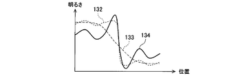
- FIG. 13B shows a change in brightness at a position where an arrow 131 is present in the image 130 of FIG. 13A. As shown by a graph 132 in FIG. 13B, it can be seen that the brightness changes greatly between the edges of the foreground and the foreground.
- the low frequency component is calculated by applying a low-pass filter to the portion of the arrow 131, the brightness is smoothed and the steep edge becomes gentle, as shown by a graph 133 in FIG. 13C.
- undershoot / overshoot occurs around the edge as shown by a graph 134 in FIG. to degrade.
- Patent Document 1 compares pixel values of a target pixel and surrounding pixels in a low-pass filter that calculates a low-frequency component, and excludes a reference object if the difference is equal to or greater than a predetermined threshold. By doing so, the low frequency component of the edge portion where the illumination light changes rapidly is smoothed to prevent the edge from becoming loose, and the occurrence of halo is suppressed.
- Patent Document 1 since the pixel values of the target pixel and the peripheral pixels are compared, the difference is caused by a difference in illumination light or a difference in reflectance of an object. It is not considered whether there is. Therefore, when the illumination light component is calculated by the method of Patent Document 1, in the region where the difference in the illumination light component is small and the difference in the reflectance component of the object is large, the reflectance component of the object is reflected in the illumination light component. When the light component is compressed, the reflected light component of the object is also compressed. As a result, the contrast is lowered and the image quality is deteriorated.
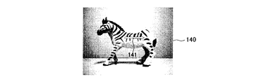
- An input image 140 illustrated in FIG. 14A is an input image in a case where subjects having greatly different reflectances are placed under uniform illumination light.
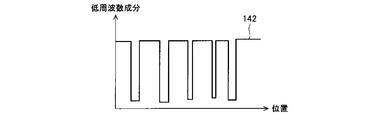
- the portion indicated by the arrow 141 is as indicated by the graph 142 in FIG. 14B.
- actual illumination light is uniform, a difference in reflectance is reflected in the illumination light component because reference is not made to neighboring pixels having greatly different pixel values when calculating.
- the converted low-frequency component becomes as shown by a graph 143 in FIG. 14C, and the component that is originally a reflectance component is compressed. Accordingly, as shown in FIG. 14D, the output image 144 has a reduced contrast and a deteriorated image quality.
- the present invention has been made in view of the above-described actual situation, and an object of the present invention is to perform image processing capable of obtaining a high-quality image having a high contrast from a dark part to a bright part without a halo from an input image. It is an object of the present invention to provide an image pickup apparatus that includes the apparatus and the image processing apparatus, and that processes the image captured by the image processing apparatus as an input image.
- the first technical means of the present invention calculates an illumination light component from the brightness of a target pixel and the brightness of surrounding pixels for an input image, and performs gradation conversion based on the illumination light component.
- An image processing apparatus that performs processing, wherein the illumination light component is calculated from distance information indicating a distance to a subject in the input image, and the distance information corresponding to the pixel of interest and the distance information corresponding to the surrounding pixels.
- the weighting for the brightness is changed according to the difference, and the range to be referred to as the peripheral pixel is calculated differently according to the distance information corresponding to the pixel of interest.
- a range in which the illumination light component is referred to as the peripheral pixel as the distance to the subject indicated by the distance information corresponding to the pixel of interest increases. It is characterized in that the calculation is performed with a smaller value.
- a high frequency component extracted from the input image is further added to an image obtained as a result of the gradation conversion processing. It is characterized by.
- an imaging apparatus comprising the image processing apparatus according to any one of the first to third technical means, wherein the photographed image is input to the image processing apparatus as the input image. It is a feature.
- FIG. 1 is a block diagram illustrating a basic configuration of an imaging apparatus according to the present invention. It is an external view which shows an example of the imaging device which concerns on this invention. It is a block diagram which shows the example of 1 structure of the imaging device which concerns on this invention. It is a figure showing the relationship between the distance to a to-be-photographed object, and parallax. It is a figure for demonstrating the process and effect of this invention using the pixel value of an image. It is a figure for demonstrating the process and effect of this invention using the pixel value of an image. It is a figure for demonstrating the process and effect of this invention using the pixel value of an image. It is a figure for demonstrating the process and effect of this invention using the pixel value of an image. It is a figure for demonstrating the process and effect of this invention using the pixel value of an image. It is a figure for demonstrating the process and effect of this invention using the pixel value of an image.
- FIG. 1 is a block diagram showing a basic configuration of an imaging apparatus according to the present invention.
- An imaging apparatus 1 illustrated in FIG. 1 includes an image processing apparatus 10 that performs image processing on an input image and distance information.
- the imaging device 1 may include a storage device (not shown) that records an image processed by the image processing device 10.
- the image processing apparatus 10 includes a brightness (Y) calculation unit 11, an illumination light component (L) calculation unit 12, and an illumination light component (L) compression unit 13.
- the Y calculation unit 11 calculates the brightness of the target pixel and the brightness of surrounding pixels with respect to the input image.
- the L calculation unit 12 calculates an illumination light component for the input image based on the brightness of the target pixel and the brightness of surrounding pixels calculated by the Y calculation unit 11. Since the brightness Y may originally exist as information, the Y calculation unit 11 is not essential in the image processing apparatus 10.
- the image processing apparatus 10 is an apparatus that performs gradation conversion processing based on the illumination light component calculated by the L calculation unit 12.
- the gradation conversion process is performed by the L compression unit 13 compressing the illumination light component.
- the L calculation unit 12 acquires distance information indicating the distance to the subject in the input image when calculating the illumination light component, and corresponds to the distance information corresponding to the target pixel and the peripheral pixels. The weighting for the brightness is changed based on the difference in the distance information. Further, when calculating the illumination light component, the L calculation unit 12 varies the range referred to as the peripheral pixel, that is, the filtering range, according to the distance information corresponding to the target pixel. Details of the respective units 11 to 13 will be described with reference to FIG.
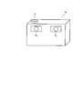
- FIG. 2 is an external view showing an example of the image pickup apparatus according to the present invention, and is an external view of the image pickup apparatus applicable also as the image pickup apparatus 1 of FIG.
- the imaging device 1a can capture two images with different viewpoints from the two cameras C L and C R by pressing the shutter S, for example.
- images with different viewpoints can also be obtained by moving a single camera manually or by an automatic moving mechanism in the imaging apparatus and shooting at different shooting timings.
- FIG. 3 is a block diagram showing an example of the configuration of the imaging apparatus according to the present invention, and is a block diagram showing an example of the internal configuration of the imaging apparatus 1a of FIG.
- An imaging apparatus 1 a illustrated in FIG. 3 illustrates a more preferable configuration example of the imaging apparatus 1 illustrated in FIG. 1, and includes an image processing apparatus 30 instead of the image processing apparatus 10.
- the imaging apparatus 1a in FIG. 3 includes the Y calculation unit 11, the L calculation unit 12, and the L compression unit 13 in the image processing apparatus 10 in FIG. 1, and includes a brightness (Y) calculation unit 32 and an illumination light component ( L)
- the calculation unit 34 and the illumination light component (L) compression unit 35 are illustrated.
- the image processing device 30 of the imaging device 1 a includes a high frequency component (H) calculation unit 31, a parallax calculation unit 33, and a high frequency component (H) addition unit 36.
- the left image and the right image are acquired as input images by photographing with the left and right cameras C L and C R.
- the left image is input to the H calculation unit 31, the Y calculation unit 32, and the parallax calculation unit 33, and the right image is input to the parallax calculation unit 33.
- the following description can be similarly applied even if the left and right images are input in reverse.
- the parallax calculation unit 33 calculates the parallax from the left image and the right image as distance information to the subject.
- a method for calculating the parallax for example, there is a block matching method as a known technique.
- the block matching method is a method for evaluating the degree of similarity between images. One area is selected from one image, the area having the highest similarity with that area is selected from the images to be compared, and the comparison target area is selected. The shift in position from the selected region with the highest similarity is parallax.
- Various evaluation functions are used to evaluate the similarity. For example, there is a method called SAD (Sum of Absolute Difference) that selects a region having the smallest sum of absolute values of differences between pixel values and luminance values of both images as a region having the highest similarity.
- SAD Sud of Absolute Difference
- the parallax increases as the distance to the subject decreases, and the parallax decreases as the distance to the subject increases. Therefore, the parallax can be treated as an index representing the distance to the subject.
- the distance information to the subject may be measured by providing the imaging device with an infrared sensor.
- the left and right cameras C are more suitable than the information obtained from the infrared sensor and the input image.
- L it is preferable better to use the parallax is calculated corresponding points from C R image.
- the Y calculation unit 32 calculates the brightness Y of each pixel from the input image.
- the calculation of the brightness Y in the Y calculation unit 32 can be performed in parallel with or before or after the calculation of the parallax amount in the parallax calculation unit 33.
- the input brightness information may be used.
- the H calculation unit 31 extracts the high frequency component H from the input image (the left image in this example), that is, calculates the high frequency component H.
- a high pass filter may be used.
- a spatial differential filter such as a Sobel filter is used.
- the calculation in the H calculation unit 31 can be performed in parallel with or before or after the calculation in the Y calculation unit 32 or the parallax calculation unit 33.
- the L calculation unit 34 calculates the illumination light component L of the input image.
- the illumination light component L can be calculated, for example, by smoothing the brightness Y described above.
- a pixel hereinafter referred to as a target pixel
- a peripheral pixel For calculating an illumination light component L at the center of the filter and a pixel around the target pixel within the filter (hereinafter referred to as a peripheral pixel)
- a difference in distance to the imaged subject is calculated from the distance information, and the brightness is weighted and averaged according to the difference.
- the weighted average weight is set so that if the difference in parallax is small, the weight is increased because the difference in the illumination light component L is considered to be close to the real space.
- the weight is reduced because there is a possibility that the difference in the illumination light component L is large because the distance is in the real space.
- FIGS. 5A to 5F a description will be given of the processing centering on the calculation and the effect of the present invention when the illumination light component L of the target pixel is calculated using a 5 ⁇ 5 filter as an example of the filter. .
- FIGS. 5A to 5F specific pixel values of the image will be described. However, similar effects can be obtained with other pixel values.
- the pixel value 51 of the image shown in FIG. 5A indicates the brightness Y of the input image within the filter range centered on the target pixel T, and the parallax value 52 shown in FIG. 5B is also the parallax value of the input image. .
- the illumination light component L shown in FIG. 5C and the reflectance component R shown in FIG. 5D are the correct value of the illumination light component L and the correct value of the reflectance component R, respectively. Therefore, the product of the respective values of the illumination light component L in FIG. 5C and the reflectance component R in FIG. 5D becomes the pixel value 51 of the image in FIG. 5A.
- the weighting coefficient 56 is calculated as shown in FIG. 5F based on the parallax value 52 shown in FIG. 5B, and the weighting coefficient 56 is weighted and smoothed.
- the illumination light component L closer to the correct value can be calculated as compared with the conventional method. That is, a favorable illumination light component L from which the reflectance component R is separated can be calculated. Note that.
- the weighting coefficient 56 is determined so as to be proportional to the parallax value 52.
- the present invention is not limited to this, and it is sufficient that the weighting coefficient 56 reflects the tendency of the parallax value 52.
- FIGS. 6A to 6D the processing and effects of the present invention are applied to an actual input image with reference to FIGS. 6A to 6D.
- an image 63 of the illumination light component L shown in FIG. 6C is obtained.
- the parallax image 62 shown in FIG. 6B is an image showing the parallax with respect to the input image 61 in FIG. 6A. The brighter the parallax is, the closer the distance is, and the darker the parallax image 62 is, the smaller the distance is. Comparing the image 63 of the illumination light component L with the parallax image 62, it can be seen that the illumination light component L changes steeply around the edges of the indoors where the distance is short and the outdoors where the distance is long.
- an image 64 of the illumination light component L shown in FIG. 6D is obtained.
- the illumination light component L image 63 calculated in the present embodiment has a steep change in the illumination light component L around the indoor and outdoor edges, whereas a simple smoothing filter is used. Is used, the illumination light component L gradually changes around the edge as shown by an image 64 in FIG. 6D, which causes a halo.
- an image 73 of the illumination light component L shown in FIG. 7C is obtained.
- the parallax image 72 shown in FIG. 7B is an image showing the parallax with respect to the input image 71 in FIG. 7A, and means that the parallax is larger and closer to the distance, and the darker the parallax is and the farther is the distance.
- the illumination light component L image 73 has a sharp change in the illumination light component L around the edge of the near subject (zebra) and the distant background. It can be seen that the illumination light component L of the portion is substantially uniform.
- FIG. 8 is a diagram illustrating the relationship between the distance to the subject and the parallax, taking specific numerical values as examples.
- the parallax between the images of the left and right cameras C L and C R decreases as the distance to the subject increases, and the amount of change in parallax with respect to the change in the distance to the subject also decreases. . That is, the difference in distance in real space is different between a disparity “1” different at a short distance and a “1” disparity different at a distant distance.
- the difference between the distances in the real space is small between the parallaxes “10” and “9”, but the parallax “2”. It can be seen that the difference in distance in the real space is large between “1” and “1”, and the difference in distance is different in the real space even if the difference in parallax is “1”. Therefore, when weighting, by considering both the parallax value of the pixel of interest and the magnitude of the difference in parallax between the pixel of interest and surrounding pixels, even when using parallax as distance information, the difference in distance in real space Can be weighted.
- the weight W for calculating the illumination light component L may be defined as in the following formula (2).
- Dij is the parallax of the pixel of interest
- is the difference between the parallax of the pixel of interest and the reference pixel
- k and l are respectively the horizontal of the reference pixel from the pixel of interest in the filter, This variable represents the amount of vertical displacement.
- the weighting function W is shown in the case where the parallax Dij is used, but the same weighting formula is also used when the information indicating the distance is used as the distance information without using the parallax. It can be applied as an example.
- the weighting reflects the difference in distance in the real space.
- Dij is the distance information of the target pixel
- is the difference between the distance information of the target pixel and the reference pixel
- k and l are the horizontal and vertical sizes of the filter, respectively.
- ) is a weighting function having Dij and
- the difference in the distance between the target pixel and the surrounding pixels is taken into consideration, so that the input image 61 in FIG. 6A or the input image 71 in FIG.
- a good illumination light component can be calculated even in a scene in which the reflected light component is reflected in the illumination light component.
- the brightness of the object is determined by the product of the reflectance of the object and the illumination light
- the brightness Y of the input image is determined using the illumination light component L and the reflected light component R.
- the L compression unit 35 in FIG. 3 performs gradation conversion processing for compressing the illumination light component. That is, the illumination light component L ′ is defined so as to compress the illumination light component L.
- the illumination light component L ′ is defined to be convex upward with respect to the illumination light component L as shown in the graph 90 in FIG. 9, the dark area becomes brighter and the brightness of the bright area is suppressed.
- the light component is compressed.
- the graph 90 is an example of conversion values individually determined for each gradation value. However, since the appearance of the image changes depending on the performance of the display device, the gradation conversion table as shown in the graph 90 has several patterns. It may be held and an optimum table may be selected in accordance with the display device.
- the brightness Y is defined as the maximum value of RGB values
- the relationship of Equation (7) is satisfied.
- the maximum value of RGB values is used for the brightness Y
- the following effects are obtained in a high saturation area.
- the process in order to brighten the dark area, when using the brightness Y calculated from the equation (1), the process is performed as a dark area and brightened, and the B value is already saturated.
- a clear image can be obtained from the dark part to the bright part by compressing the illumination light component. Further, in a region where L is continuous, the difference in the value of the illumination light component L between adjacent pixels is small, that is, the difference in L ′ / L between adjacent pixels is also small. The contrast in between is maintained, and a high-quality image with high contrast from the dark part to the bright part can be obtained.
- the filter When calculating the illumination light component, if the filter size is extremely small, the illumination light component may not be sufficiently smoothed. Therefore, it is preferable that the filter has a certain size. However, when the size of the filter is large, for a distant subject, even if the illumination light changes steeply in the real space, the difference in distance cannot be determined on the distance information. There is a possibility that the edges become smooth and the edges become gradual, causing halos. Actually, distance information calculation means such as left and right cameras C L and C R (that is, stereo cameras) that obtain parallax information have low calculation resolution in the distance. For example, as shown by a graph 40 in FIG.
- the change in parallax with respect to the change in distance decreases, the resolution with respect to the parallax distance decreases, and the parallax converges at a distance greater than a certain threshold. Therefore, when there are two subjects at different distances in the distance, even if they exist at different distances in the real space, the difference in distance may not be determined on the distance information.
- FIGS. 10A to 10D An illumination light component calculation method when there are a plurality of subjects in the distance will be described with reference to FIGS. 10A to 10D.
- the subject 101 is shown in the foreground and the two subjects 102 and 103 are shown in the background.
- there is an example in which there are two subjects in the distance but the following processing can be similarly applied even if there are three or more subjects.
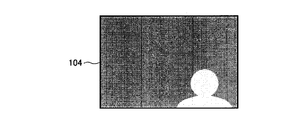
- An image indicating distance information with respect to the input image 100 is a distance image 104 illustrated in FIG. 10B. In the distance image 104, the brighter the color, the smaller the distance to the subject.
- the subject 102 and the subject 103 exist at different distances in the real space, but the input distance information is the same distance as in the distance image 104 of FIG. 10B.
- the distance information is different between the subject 101 and the subject 102, and between the subject 101 and the subject 103, so that the difference in distance can be considered.
- the filter size is reduced as shown by the filter 108 in the image 107 in FIG. 10D (showing the reduced filter in the input image 100 in FIG. 10A).
- the filter 108 in the image 107 in FIG. 10D shows the reduced filter in the input image 100 in FIG. 10A.
- a distance adaptive filter that varies the filter size according to the distance information, it is possible to handle a plurality of subjects having different distances in the real space as subjects at the same distance when calculating the illumination light component. It can be avoided.
- the illumination light component may not be sufficiently smoothed, but the filtering area in the real space per unit filter size increases as the distance to the subject increases. When the distance to the subject is large, a sufficient area can be filtered in the real space even if the filter size is reduced.
- FIGS. 11A to 11C are diagrams for comparing the relative sizes of the area to be filtered and the size of the subject.
- FIG. 11A shows a photographed image when the subject 111 is photographed from a short distance
- FIG. 11B shows a photographed image when the subject 111 is photographed from a long distance.
- each square box represents a pixel, and for convenience, an image composed of 11 ⁇ 11 pixels is illustrated.
- the subject 111 is shown large, and in FIG. 11B, the subject 111 is shown small.
- the size of the filter 112 used for calculating the illumination light component is set to 4 ⁇ 4 and is indicated by a dotted frame in the drawing.
- a part of the subject 111 is filtered in FIG. 11A, and the entire subject 111 is filtered in FIG. 11B. That is, when the filter size is the same, the area in the real space to be filtered increases as the distance to the subject increases. Therefore, even if the filter size used for calculating the illumination light component is reduced according to the distance to the subject, the same region can be filtered in the real space. For example, in FIG. 11B, as in the filter 113 shown in FIG. 11C, a region in the real space equivalent to the 4 ⁇ 4 filter shown in FIG. 11A can be filtered with a filter size of 2 ⁇ 2. As described above, even if the filter size used for calculating the illumination light component is reduced according to the distance to the subject, it is possible to filter a region in real space sufficient to smooth the illumination light component.
- the filter size may be reduced as the distance to the subject increases, for example, as shown by the graph 120 in FIG. That is, as the distance to the subject indicated by the distance information corresponding to the target pixel is larger, the range referred to as the peripheral pixel may be made smaller.
- the H calculation unit 31 and the H addition unit 36 are provided.
- the periphery of the edge of the illumination light component L becomes brighter on the side where the value of the illumination light component L is small, and the value of the illumination light component L is large. In order to suppress the brightness on the side, the contrast around the edge of the illumination light component L is reduced considerably.
- the H addition unit 36 adds the high-frequency component H of the input image calculated by the H calculation unit 31 to the image that has been subjected to the gradation conversion process for compressing the illumination light component L, so that the illumination light component L As a result, the contrast around the edges of the image becomes higher and the image quality is improved.
- the gradation conversion that calculates the illumination light component of the input image in consideration of the distance to the subject, compresses the calculated illumination light component, and maintains the reflected light component.
- FIG. 1 an imaging apparatus including an image processing apparatus that performs image processing
- the image processing apparatus according to the present invention (the image processing apparatus 10 in FIG. 1 or the image processing apparatus 30 in FIG. 3) is illustrated in FIG.
- the image pickup apparatus may not be provided.
- the same effect can be obtained by providing the display apparatus such as a liquid crystal display.
- the image processing device When the image processing device is provided in the display device, the input image and the distance information are input to the display device, and the image processing device converts the input image into an image with high contrast and reduced halo as in the first embodiment. Image processing to be converted is performed, and an output image is displayed on the display device.
- the parallax of the left and right cameras C L and C R may be calculated in the display device as the distance information.
- a video device such as a personal computer (PC) or a Blu-ray recorder is equipped with the image processing device according to the present invention, and the input image is converted into an output image with high contrast and suppressed halo. Good.
- each component of the image processing apparatus such as each unit 11 to 13 in the image processing apparatus 10 illustrated in FIG. 1 or each unit 31 to 36 in the image processing apparatus 30 illustrated in FIG.
- it can be realized by hardware such as a DSP (Digital Signal Processor), a memory, a bus, an interface, and a peripheral device, and software that can be executed on these hardware.
- Part or all of the hardware can be mounted as an integrated circuit / IC (Integrated Circuit) chip set, and in this case, the software may be stored in the memory.
- all the components of the present invention may be configured by hardware, and in that case as well, part or all of the hardware can be mounted as an integrated circuit / IC chip set. .
- a recording medium in which a program code of software for realizing the functions in the various configuration examples described above is recorded is supplied to a display device, a PC, a recorder, or the like as an image processing device, and a microprocessor in the device
- the object of the present invention can be achieved by executing the program code by the DSP.
- the software program code itself realizes the functions of the above-described various configuration examples. Even if the program code itself or a recording medium (external recording medium or internal storage device) on which the program code is recorded is used.
- the present invention can be configured by the control side reading and executing the code.
- Examples of the external recording medium include various media such as an optical disk such as a CD, a DVD, and a BD, and a nonvolatile semiconductor memory such as a memory card.
- Examples of the internal storage device include various devices such as a hard disk and a semiconductor memory.
- the program code can be downloaded from the Internet and executed, or received from a broadcast wave and executed.
Landscapes
- Engineering & Computer Science (AREA)
- Multimedia (AREA)
- Signal Processing (AREA)
- Physics & Mathematics (AREA)
- General Physics & Mathematics (AREA)
- Theoretical Computer Science (AREA)
- Image Processing (AREA)
- Facsimile Image Signal Circuits (AREA)
Abstract
入力画像から、ハローがなく、暗部から明部までコントラストの高い高画質な画像を得ることが可能な画像処理装置を提供する。画像処理装置(10)は、入力画像に対し、注目画素の明るさと周辺画素の明るさから照明光成分を算出する照明光成分算出部(12)を備え、照明光成分に基づき階調変換処理を施す。照明光成分算出部(12)は、照明光成分の算出に際し、入力画像における被写体までの距離を示す距離情報を取得し、注目画素に対応した距離情報と周辺画素に対応した距離情報の差異に基づいて、明るさに対する重み付けを変え、かつ、注目画素に対応した距離情報に応じて、周辺画素として参照する範囲を異ならせる。
Description
本発明は、高画質な映像を得るための画像処理装置、及びその画像処理装置を備えた撮像装置に関する。
近年、デジタルスチルカメラやデジタルビデオカメラなどの撮像装置の高機能化や高画質化が進んでいる。撮像画像の画質を決める要因の1つとして、コントラストがある。コントラストとは、画像中の暗部と明部の差を意味し、コントラストの高い方が明瞭な画像になる。また、ダイナミックレンジ(以下、DR)も画質を決める要因の1つである。DRとは、識別可能な信号の最小値と最大値の比を意味するが、以下では、DRを撮影シーン中の最大輝度と最小輝度の比とする。
液晶ディスプレイなどの表示装置に画像を表示する際、表示装置の表現可能な明るさの幅には限りがあるため、入力される画像と表示装置の性能に依っては、暗部の階調が失われる、いわゆる黒潰れが生じることがある。そこで、元画像の画素値を大きくする階調変換処理を施すことで、黒潰れが解消され暗部の明瞭な画像を得ることができる。しかし、画素値を大きくすることで、明部が飽和する、いわゆる白飛びが生じたりコントラストが低下したりし、明部領域では画質が劣化する。特に、DRの高いシーンを撮影した画像は、暗部と明部が共存する可能性が高く、上述の課題が生じることが多い。
この課題に対し、Retinex理論に基づく階調変換技術が提案されている。Retinex理論とは、人間の視覚特性をモデル化した理論であり、物体の明るさは物体の反射率と照明光の積で決まり、物体の明るさに対する目の知覚は物体の反射率に強い相関を示すというものである。したがって、階調変換する際に、入力画像の照明光成分のみを圧縮し、物体の反射率成分を維持すれば、黒潰れ・白飛びがなくコントラストの高い画像を得ることができる。撮影画像から照明光と反射率を正確に分離することは容易ではないが、実空間において照明光は連続的に変化している可能性が高いと仮定すると、入力画像にローパスフィルタをかけて算出した低周波数成分を照明光成分とみなすことができる。そして、照明光成分を圧縮し、圧縮した照明光成分に入力画像の反射率成分を掛け合わせることにより、コントラストの高い画像を得ることができる。
しかし、実際には照明光が不連続に変化している場合もあり、前述の仮定に基づいた階調変換処理を施すと、照明光が急激に変化するエッジ周辺で、ハローと呼ばれるアンダーシュート・オーバーシュートが生じ、画質が劣化する。
ハローの発生原理について、図13A~図13Dを参照しながら説明する。図13Aは、屋内と屋外を同時に撮影したシーン、つまり屋内と屋外とが混在したシーンの画像の一例を示している。図13Bは、図13Aの画像130中の矢印131がある位置での明るさの変化を示している。図13Bのグラフ132で示すように、後景と前景のエッジで明るさが大きく変化しているのが分かる。矢印131の部分について、ローパスフィルタをかけて低周波数成分を算出すると、図13Cのグラフ133で示すように、明るさが平滑化され急峻なエッジが緩やかになる。そして、算出した低周波数成分を基に、入力画像に対し低周波数成分を圧縮する処理を施すと、図13Dのグラフ134で示すように、エッジ周辺でアンダーシュート・オーバーシュートが生じてしまい画質が劣化する。
ハローを抑制するために、特許文献1では、低周波数成分を算出するローパスフィルタにおいて、注目画素と周辺画素の画素値を比較し、その差が所定の閾値以上である場合には参照対象から除外することで、照明光が急激に変化するエッジ部分の低周波数成分が平滑化されエッジが緩やかになるのを回避し、ハローの発生を抑制している。
しかしながら、特許文献1では、注目画素と周辺画素との画素値を比較しているため、その差が照明光の違いに起因するものであるか、または物体の反射率の違いに起因するものであるのかが考慮されていない。したがって、特許文献1の方法で照明光成分を算出すると、照明光成分の差異が小さく物体の反射率成分の差異が大きい領域は、照明光成分に物体の反射率成分が反映されてしまい、照明光成分を圧縮した際に物体の反射光成分も圧縮されてしまう。その結果、コントラストが低下して画質が劣化する。
図14A~図14Dを参照しながら、従来技術の課題であるコントラストの低下を説明する。図14Aに示す入力画像140は、反射率が大きく異なる被写体が一様な照明光下に置かれている場合の入力画像である。入力画像140について、特許文献1の方法で低周波数成分を算出すると、矢印141で示す部分については、図14Bのグラフ142で示すようになる。実際の照明光は一様であるが、算出する際に画素値の大きく異なる周辺画素を参照しないため、反射率の差異が照明光成分に反映されてしまう。そして、算出した低周波数成分を圧縮すると、変換後の低周波数成分は図14Cのグラフ143で示すようになり、本来ならば反射率成分である成分が圧縮されてしまう。したがって、図14Dに示すように、出力される画像144はコントラストが低下し画質が劣化する。
本発明は、上述のような実状に鑑みてなされたものであり、その目的は、入力画像から、ハローがなく、暗部から明部までコントラストの高い高画質な画像を得ることが可能な画像処理装置、及びその画像処理装置を備え撮影した画像を入力画像としてその画像処理装置で処理する撮像装置を提供することにある。
上記課題を解決するために、本発明の第1の技術手段は、入力画像に対し、注目画素の明るさと周辺画素の明るさから照明光成分を算出し、該照明光成分に基づき階調変換処理を施す画像処理装置であって、前記照明光成分を、前記入力画像における被写体までの距離を示す距離情報から算出した前記注目画素に対応した前記距離情報と前記周辺画素に対応した前記距離情報の差異に応じて、明るさに対する重み付けを変え、かつ、前記注目画素に対応した前記距離情報に応じて、前記周辺画素として参照する範囲を異ならせて算出することを特徴としたものである。
本発明の第2の技術手段は、第1の技術手段において、前記照明光成分を、前記注目画素に対応した前記距離情報が示す被写体までの距離が大きい程、前記周辺画素として参照する範囲を小さくして算出することを特徴としたものである。
本発明の第3の技術手段は、第1または第2の技術手段において、前記階調変換処理が施された結果の画像に対して、更に前記入力画像から抽出した高周波数成分を加算することを特徴としたものである。
本発明の第4の技術手段は、第1~第3のいずれかの技術手段における画像処理装置を備える撮像装置であって、撮影した画像を前記入力画像として前記画像処理装置に入力することを特徴としたものである。
本発明によれば、ハローがなく、暗部から明部までコントラストの高い高画質な画像を得ることが可能になる。
<第1の実施形態>
以下、添付図面を参照しながら、本発明に係る撮像装置についてその好適な実施の形態について説明する。
以下、添付図面を参照しながら、本発明に係る撮像装置についてその好適な実施の形態について説明する。
図1は、本発明に係る撮像装置の基本的な構成を示すブロック図である。図1で示す撮像装置1は、入力画像及び距離情報について画像処理を行う画像処理装置10を備える。なお、その他、通常の撮像装置と同様に、撮像装置1には画像処理装置10で処理された画像を記録する記憶装置(図示せず)を備えてもよい。
画像処理装置10は、明るさ(Y)算出部11、照明光成分(L)算出部12、及び照明光成分(L)圧縮部13を備える。Y算出部11は、入力画像に対し、注目画素の明るさと周辺画素の明るさを算出する。L算出部12は、入力画像に対し、Y算出部11で算出された注目画素の明るさと周辺画素の明るさに基づいて照明光成分を算出する。なお、元々明るさYが情報として存在する場合もあるため、画像処理装置10において、Y算出部11は必須ではない。
そして、画像処理装置10は、L算出部12で算出した照明光成分に基づき階調変換処理を施す装置である。この例では、この階調変換処理を、L圧縮部13が照明光成分を圧縮することで行うものとする。
そして、本発明の主たる特徴として、L算出部12は、照明光成分の算出に際し、入力画像における被写体までの距離を示す距離情報を取得し、注目画素に対応した距離情報と周辺画素に対応した距離情報の差異に基づいて、明るさに対する重み付けを変える。更にL算出部12は、照明光成分の算出に際し、注目画素に対応した距離情報に応じて、周辺画素として参照する範囲、つまりフィルタリングの範囲を異ならせるようにする。各部11~13の詳細については図3等を参照しながら説明する。
図2は、本発明に係る撮像装置の一例を示す外観図で、図1の撮像装置1としても適用可能な撮像装置の外観図である。以下では、図2に示すように撮像装置1aには、左カメラCL、右カメラCRがそれぞれ左眼用、右眼用として配置されている場合について述べる。撮像装置1aは、例えばシャッタSの押下により、2つのカメラCL,CRから視点の異なる2つの画像が撮影できるものである。ただし、視点の異なる画像は1つのカメラでも手動や撮像装置内の自動の移動機構により移動させ、撮影タイミングをずらして撮影することなどでも得られる。
図3は、本発明に係る撮像装置の一構成例を示すブロック図で、図2の撮像装置1aの内部の構成例を示すブロック図である。図3に示す撮像装置1aは、図1の撮像装置1のより好ましい構成例を示しており、画像処理装置10の代わりに画像処理装置30を備える。図3の撮像装置1aは、図1の画像処理装置10におけるY算出部11、L算出部12、及びL圧縮部13を備えており、それぞれ明るさ(Y)算出部32、照明光成分(L)算出部34、及び照明光成分(L)圧縮部35として図示している。その他、撮像装置1aの画像処理装置30は、高周波数成分(H)算出部31、視差算出部33、及び高周波数成分(H)加算部36を備える。
まず、撮像装置1aでは、左右カメラCL,CRでの撮影により左画像、右画像を入力画像として取得する。左画像は、H算出部31、Y算出部32、及び視差算出部33に入力され、右画像は、視差算出部33に入力される。無論、左右の画像は逆に入力しても以下の説明を同様に適用することができる。
次に、視差算出部33は、被写体までの距離情報として、これら左画像、右画像から視差を算出する。視差を算出する方法として、例えば、公知の技術として、ブロックマッチング法がある。ブロックマッチング法とは、画像間の類似度を評価する方法であり、一方の画像からある領域を選択し、その領域と最も類似度の高い領域を比較する画像から選択し、比較対象の領域と選択された最も類似度の高い領域との位置のずれが視差となる。類似度の評価には様々な評価関数が用いられる。例えば、SAD(Sum of Absolute Difference)と言われる、両画像の画素値や輝度値の差異の絶対値の総和が最小となる領域を最も類似度の高い領域として選択する方法がある。
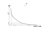
図4を参照しながら、被写体までの距離と視差の関係について説明する。左右カメラCL,CRの画像間の視差dは、被写体までの距離Z、基線長B、焦点距離fを用いてd=Bf/Zと表され、被写体までの距離Zと反比例の関係にあり、図4のグラフ40に示すように、被写体までの距離が近いほど視差は大きくなり、被写体までの距離が遠いほど視差は小さくなる。したがって、視差を被写体までの距離を表す指標として扱うことができる。また、被写体までの距離情報を、撮像装置に赤外線センサを備えて測定してもよい。
ただし、後述する画像処理過程において距離情報を用いる際に、入力画像と距離情報とを対応させる必要があることを考慮すると、赤外線センサから得られる情報と入力画像を対応させるよりは、左右カメラCL,CRの画像から対応点を算出している視差を用いる方が好適である。
次に、Y算出部32が、入力画像から各画素の明るさYを算出する。明るさYは入力画像の画素値から算出することができ、例えば、入力画像がRGB値を持つカラー画像であれば、国際電気通信連合で定義されているRGBからYCbCrへの変換式より、
Y=0.29891×R+ 0.58661×G+0.11448×B ・・・(1)
と定義してもよい。
Y=0.29891×R+ 0.58661×G+0.11448×B ・・・(1)
と定義してもよい。
また、明るさYをRGB値の最大値、Y=Max(R,G,B)としてもよい。RGB値の最大値を用いることで、後述する階調変換処理において画質改善効果が得られる。なお、Y算出部32における明るさYの算出は、視差算出部33における視差量の算出と並行して或いはその前後に行うことができる。また、照度センサ等により予め明るさの情報がある場合には、入力画像から明るさを算出する必要はなく、入力された明るさの情報を用いてもよい。
次に、H算出部31が、入力画像(この例では左画像)から高周波数成分Hの抽出、つまり高周波数成分Hを算出する。高周波数成分Hを算出するにはハイパスフィルタを用いればよく、例えば、ソーベルフィルタのような空間微分フィルタが用いられる。なお、H算出部31における算出は、Y算出部32や視差算出部33における算出と並行して或いはその前後に行うことができる。
次に、L算出部34が、入力画像の照明光成分Lを算出する。この算出方法について説明する。照明光成分Lは、例えば、上述の明るさYを平滑化することで算出できる。所定の領域内(フィルタ内)で平滑化処理を行う際、フィルタ中央の照明光成分Lを算出する画素(以下、注目画素)とフィルタ内の注目画素周辺の画素(以下、周辺画素)にそれぞれ撮像されている被写体までの距離の差異を距離情報から算出し、その差異に応じて明るさを加重平均する。距離情報として視差を用いる場合、加重平均の重み付けは、視差の差が小さい場合は実空間内で近い位置にあり照明光成分Lの差異も小さいと考えられることから重みを大きくし、視差の差が大きい場合は実空間内で離れた位置にあり照明光成分Lの差異が大きい可能性があることから重みを小さくする。
図5A~図5Fを参照しながら、フィルタの一例として5×5のフィルタを用いて注目画素の照明光成分Lを算出する場合について、その算出を中心とした処理及び本発明の効果を説明する。なお、図5A~図5Fでは、具体的な画像の画素値を挙げて説明するが、他の画素値でも同様の効果が得られる。
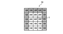
図5Aで示す画像の画素値51は、注目画素Tを中心としたフィルタ範囲内の入力画像の明るさYを示しており、図5Bで示す視差値52は、同じく入力画像の視差値である。また、図5Cで示す照明光成分Lと図5Dで示す反射率成分Rはそれぞれ、照明光成分Lの正解値、反射率成分Rの正解値とする。したがって、図5Cの照明光成分Lと図5Dの反射率成分Rのそれぞれの値の積が、図5Aの画像の画素値51となる。
図5Aの画素値51を用いて、注目画素Tについて単純な平滑化をすると、
L = ( 50×1 + 100×16 + 150×3 + 200×5 ) / 25 = 124
となる。
L = ( 50×1 + 100×16 + 150×3 + 200×5 ) / 25 = 124
となる。
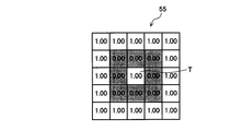
ここで、特許文献1に記載されている方法に基づき、明るさ(注目画素Tとの明るさの差)に応じて平滑化対象とするか否かを判定し、平滑化対象とする画素の重みを1、対象としない画素の重みを0として平滑化する。例えば、平滑化するか否かの画素値の差異を75とすると、重み付けは図5Eに示す重み付け係数55となり、平滑化すると、
L = ( 50×1.0×1 + 100×1.00×16 + 150×0.00×3 + 200×0.00×5 ) / ( 1.0×1 + 1.00×16 + 0.00×3 + 0.00×5 )
= 97
となり、図5Cに示す注目画素Tの正解値「200」と比べてはるかに小さな値となる。
L = ( 50×1.0×1 + 100×1.00×16 + 150×0.00×3 + 200×0.00×5 ) / ( 1.0×1 + 1.00×16 + 0.00×3 + 0.00×5 )
= 97
となり、図5Cに示す注目画素Tの正解値「200」と比べてはるかに小さな値となる。
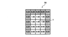
一方、本実施形態では、図5Bに示す視差値52に基づいて図5Fに示すように重み付け係数56を算出し、その重み付け係数56で重み付けをして平滑化する。その結果は、
L = ( 50×1.0×1 + 100×0.25×13 + 100×0.50×3 + 150×0.5×3 + 200×1.00×5 ) / ( 1.0×6 + 0.50×6 + 0.25×13 )
= 143
となり、従来の方法と比較して、より正解値に近い照明光成分Lを算出することができることが分かる。すなわち、反射率成分Rを分離した良好な照明光成分Lを算出することができる。なお。ここでは、視差値52に比例するように重み付け係数56を決めた例を挙げているが、これに限らず、重み付け係数56が視差値52の傾向を反映したものであればよい。
L = ( 50×1.0×1 + 100×0.25×13 + 100×0.50×3 + 150×0.5×3 + 200×1.00×5 ) / ( 1.0×6 + 0.50×6 + 0.25×13 )
= 143
となり、従来の方法と比較して、より正解値に近い照明光成分Lを算出することができることが分かる。すなわち、反射率成分Rを分離した良好な照明光成分Lを算出することができる。なお。ここでは、視差値52に比例するように重み付け係数56を決めた例を挙げているが、これに限らず、重み付け係数56が視差値52の傾向を反映したものであればよい。
その効果を分かりやすくするために、図6A~図6Dを参照しながら、本発明の処理及び効果を実際の入力画像に適用して説明する。図6Aに示す入力画像61に対して、本実施形態の方法で照明光成分Lを算出すると、図6Cに示す照明光成分Lの画像63のようになる。図6Bで示す視差画像62は、図6Aの入力画像61に対する視差を示す画像であり、明るい程視差が大きく距離が近く、暗い程視差が小さく距離が遠いことを意味している。照明光成分Lの画像63と視差画像62とを対応させて比較すると、距離が近い屋内と距離が遠い屋外とのエッジ周辺で照明光成分Lが急峻に変化しているのが分かる。
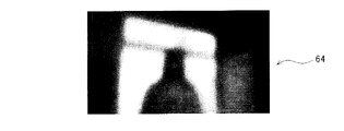
本発明の効果を確認するための比較例として、単純な平滑化フィルタを用いて照明光成分Lを算出すると、図6Dに示す照明光成分Lの画像64のようになる。図6Cで示したように本実施形態で算出した照明光成分Lの画像63が、屋内と屋外とのエッジ周辺で照明光成分Lが急峻に変化しているのに対し、単純な平滑化フィルタを用いた場合、図6Dの画像64で示すようにエッジ周辺で照明光成分Lが緩やかに変化しており、これがハローの原因となる。
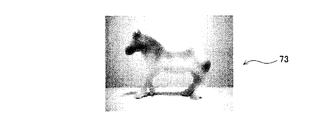
同様に、図7A~図7Dを参照しながら、本発明の処理及び効果を実際の入力画像(図6A~図6Fの例とは異なる入力画像)に適用して説明する。図7Aに示す入力画像71に対して、本実施形態の方法で照明光成分Lを算出すると、図7Cに示す照明光成分Lの画像73のようになる。図7Bで示す視差画像72は、図7Aの入力画像71に対する視差を示す画像であり、明るい程視差が大きく距離が近く、暗い程視差が小さく距離が遠いことを意味している。照明光成分Lの画像73は、視差画像72と比べると、距離が近い手前の被写体(シマウマ)と距離が遠い背景とのエッジ周辺で照明光成分Lが急峻に変化しており、かつシマウマの部分の照明光成分Lがほぼ均一になっていることが分かる。
本発明の効果を確認するための比較例として、特許文献1に記載されている方法で照明光成分Lを算出すると、図7Dに示す照明光成分Lの画像74のようになる。図7Cで示したように本実施形態で算出した照明光成分Lの画像73が、手前の被写体の照明光成分Lがほぼ均一になっているのに対し、特許文献1に記載の方法で処理した場合、図7Dの画像74で示すように、手前の被写体の照明光成分Lが平滑化されず、照明光成分Lに反射光成分Rが含まれてしまっているのが分かる。これにより、特許文献1に記載の方法では、照明光成分Lを圧縮すると反射光成分Rも圧縮されてしまいコントラストが低下することになる。
ここで、図8を参照しながら、距離情報として視差を用いる場合の重み付けについて更に詳しく述べる。図8は、被写体までの距離と視差の関係を、具体的な数値を例に挙げて示す図である。図4のグラフ40に示すように、左右カメラCL,CRの画像間の視差は、被写体までの距離が遠くなるにつれて小さくなるとともに、被写体までの距離の変化に対する視差の変化量も小さくなる。すなわち、近い距離で視差が「1」異なるのと、遠い距離で視差が「1」異なるのとでは、実空間内での距離の差は異なる。例えば、被写体までの距離と視差とが図8に示すグラフ80のような関係であるとすると、視差「10」と「9」とでは実空間内の距離の差は小さいが、視差「2」と「1」とでは実空間内の距離の差が大きく、視差の差異が同じ「1」であっても、実空間内では距離の差が異なることがわかる。そこで、重み付けをする際、注目画素の視差値と、注目画素と周辺画素との視差の差異の大きさを共に考慮することで、距離情報として視差を用いる場合でも、実空間内の距離の差を反映する重み付けをすることができる。
例えば、照明光成分Lを算出する際の重みWを以下に示す数式(2)のように定義すればよい。ここで、Dijは注目画素の視差、|Dij - Di+k,j+l|は注目画素と参照画素の視差の差異、k、lはそれぞれ、フィルタ内における参照画素の注目画素からの横、縦方向のずれ量を表す変数である。なお、数式(2)では、重み付け関数Wの一例を視差Dijを用いた場合で示しているが、距離情報として視差を用いずに距離を示す情報を用いる場合にも、同様の重み付けの式が一例として適用できる。

注目画素の視差を「10」、周辺画素の視差を「9」とすると、視差「10」に対して差異は「1」であるから、重みは1-1/10=0.9となる。注目画素の視差を「2」、周辺画素の視差を「1」とすると、視差「2」に対して差異は「1」であるから、重みは1-1/2=0.5となり、視差の差異が同じ値であっても、実空間内の距離の差を反映した重み付けとなる。
注目画素と参照画素の距離の差異を考慮した照明光成分Lの算出方法を数式で表すと、以下に示す数式(3)のようになる。
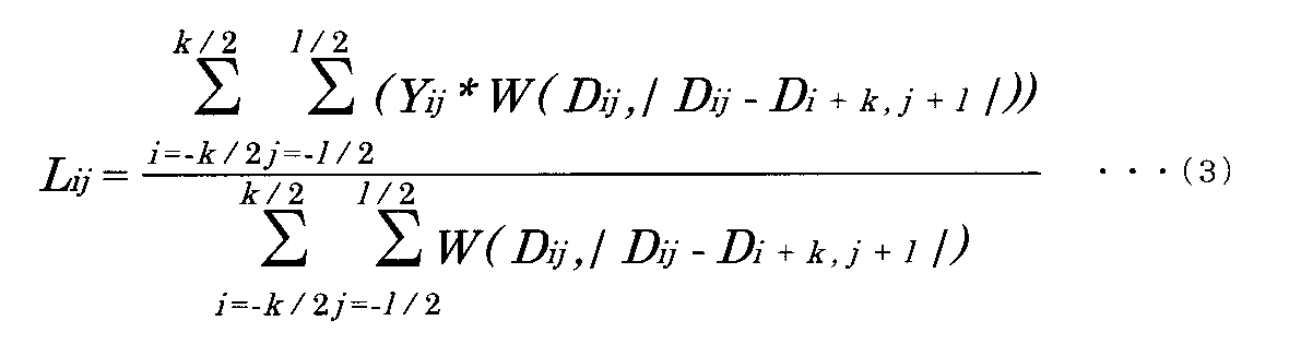
ここで、Dijは注目画素の距離情報、|Dij - Di+k,j+l|は注目画素と参照画素の距離情報の差異、k、lはそれぞれフィルタの横、縦方向のサイズである。また、W(Dij,|Dij - Di+k,j+l|)は、Dij、|Dij - Di+k,j+l|を変数とする重み付け関数である。
上述のように、本実施形態では、照明光成分Lを算出する際に、注目画素と周辺画素との距離の差異を考慮することで、図6Aの入力画像61や図7Aの入力画像71ような、従来の算出方法では照明光成分に反射光成分が反映されてしまうシーンにおいても、良好な照明光成分を算出することができる。
次に、階調変換処理について述べる。物体の明るさは物体の反射率と照明光の積で決まることから、入力画像の明るさYを、照明光成分Lと反射光成分Rを用いて、
Y=R×L ・・・(4)
と表す。また、階調変換後の画像の明るさをY′、照明光成分をL′、反射光成分をR′とすると、
Y′=R′×L′ ・・・(5)
と表せる。
Y=R×L ・・・(4)
と表す。また、階調変換後の画像の明るさをY′、照明光成分をL′、反射光成分をR′とすると、
Y′=R′×L′ ・・・(5)
と表せる。
本実施形態では、入力画像の照明光成分Lのみを圧縮し、反射率成分Rを維持するよう階調変換を施す。すなわち、階調変換の前後で反射率成分が変化しない処理を施せばよく、次の数式(6)の関係が成り立てばよい。
R=R′ ・・・(6)
R=R′ ・・・(6)
数式(4)~(6)より反射率成分を消去すると、
Y′=Y×L′/L ・・・(7)
となり、階調変換後の画像の明るさY′が、入力画像の明るさY、照明光成分L、階調変換後の画像の照明光成分L′のみで表される。したがって、階調変換後の照明光成分L′を定義すれば、反射光成分を算出することなく、反射率成分を維持する階調変換処理を施すことができる。
Y′=Y×L′/L ・・・(7)
となり、階調変換後の画像の明るさY′が、入力画像の明るさY、照明光成分L、階調変換後の画像の照明光成分L′のみで表される。したがって、階調変換後の照明光成分L′を定義すれば、反射光成分を算出することなく、反射率成分を維持する階調変換処理を施すことができる。
次に、照明光成分L′の定義について説明する。本実施形態では、図3のL圧縮部35が、照明光成分を圧縮する階調変換処理を施す。すなわち、照明光成分Lを圧縮するよう照明光成分L′を定義する。
図9を参照しながら、この圧縮方法の一例を説明する。図9で示す、グラフ90のように、照明光成分Lに対し照明光成分L′が上に凸になるよう定義すると、暗部領域はより明るくなり、明部領域は明るさが抑えられ、照明光成分が圧縮される。なお、グラフ90は各階調値について個別に定めた変換値の一例であるが、表示装置の性能に依って画像の見え方は変わるため、このグラフ90で示すような階調変換テーブルを数パターン保持しておき、表示装置に合わせて最適なテーブルを選択するようにしておいてもよい。
上述の圧縮の処理を、RGB値を有するカラー画像に適用する場合、階調変換後の画素値をR′G′B′とすると、以下の数式(8)~(10)に示すように、入力画像の画素値RGBに対しL′/Lを掛ければよい。
R′= R×L′/L ・・・(8)
G′= G×L′/L ・・・(9)
B′= B×L′/L ・・・(10)
G′= G×L′/L ・・・(9)
B′= B×L′/L ・・・(10)
R′G′B′と数式(1)からY′を算出すると、
Y′=0.29891×R′+ 0.58661×G′+0.11448×B′
=(0.29891×R+ 0.58661×G+0.11448×B)×L′/L
=Y×L′/L
となり、数式(7)の関係を満たしていることがわかる。
Y′=0.29891×R′+ 0.58661×G′+0.11448×B′
=(0.29891×R+ 0.58661×G+0.11448×B)×L′/L
=Y×L′/L
となり、数式(7)の関係を満たしていることがわかる。
また、明るさYをRGB値の最大値と定義する場合も同様に、数式(7)の関係が満たされる。明るさYをRGB値の最大値を用いる場合、彩度が高い領域において以下のような効果がある。彩度が高い画素、例えば、RGB値が(R,G,B)=(10,10,255)という画素について、数式(1)を用いて明るさYを算出すると、Y=38となり、RGB値の最大値を用いるとY=255となる。上述の階調変換処理では、暗い領域をより明るくするため、数式(1)から算出した明るさYを用いると、暗い領域としてみなし明るくする処理を施し、B値はすでに飽和しているため、R、G値のみが増加し、彩度が低下する可能性がある。一方、明るさYとしてRGB値の最大値を用いると、上述の画素は飽和した明るい画素とみなし明るさを抑えるため、彩度が低下しない。したがって、数式(8)~(10)に示す階調変換処理を施す場合は、RGB値の最大値を明るさYとする方が好適である。
上述の階調変換処理により、照明光成分を圧縮することで暗部から明部まで明瞭な画像を得ることができる。また、Lが連続的な領域では近接する画素間の照明光成分Lの値の差異が小さく、すなわち、近接画素間のL′/Lの差異も小さいため、上述の階調変換処理によって近接画素間のコントラストは維持され、暗部から明部までコントラストの高い高画質な画像が得られる。
また、図3のL算出部34の処理に関し、照明光成分算出に用いるフィルタサイズを被写体までの距離に応じて変えることで、更なる画質改善効果が得られる。この処理について具体的に説明する。
照明光成分を算出する際、フィルタサイズが極端に小さいと照明光成分が十分に平滑化されない可能性があるため、フィルタはある程度の大きさがある方が好適である。しかし、フィルタのサイズが大きい場合、遠方にある被写体については、実空間内では照明光が急峻に変化していても、距離情報上では距離の差異を判別できず、その結果、照明光成分が平滑化されエッジが緩やかになりハローの原因となる可能性がある。実際、赤外線センサや視差情報を得る左右カメラCL,CR(つまりステレオカメラ)といった、距離情報の算出手段は、遠方の算出分解能が低く、例えば、図4のグラフ40で示したように、被写体までの距離が遠いほど距離の変化に対する視差の変化が小さくなり、視差の距離に対する分解能が低下し、ある閾値以上の距離で視差が収束する。したがって、遠方の異なる距離に2つの被写体が存在する場合、実空間内において異なる距離に存在していても、距離情報上では距離の差異を判別できないことがある。
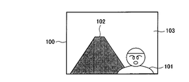
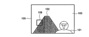
遠方に複数の被写体がある場合の照明光成分算出方法について、図10A~図10Dを参照しながら説明する。図10Aで示す入力画像100には、前景に被写体101、後景に2つの被写体102,103が写っている。なお、この例では遠方に2つの被写体がある例を挙げているが、3つ以上の被写体があっても以下の処理は同様に適用できる。また、入力画像100に対する距離情報を示す画像は、図10Bで示す距離画像104のようになる。距離画像104では、明るい色ほど被写体までの距離が小さいことを意味している。
被写体102と被写体103は実空間内においては異なる距離に存在するが、図10Bの距離画像104のように、入力される距離情報は共に同じ距離になってしまう。図10Aの入力画像100及び図10Bの距離画像104を用いて照明光成分を算出すると、被写体101と被写体102、被写体101と被写体103とはそれぞれ距離情報が異なるため、距離の差異を考慮できる。一方で、被写体102と被写体103は距離情報に差異がなく、図10Cの画像105(図10Aの入力画像100にフィルタを図示したもの)で示すように、フィルタ106内で被写体102と被写体103を同じ距離にある被写体として扱うことになり、実空間内では照明光の異なる領域の照明光成分を平滑化して算出する可能性がある。
そこで、本実施形態では、被写体までの距離が大きい場合は、図10Dの画像107(図10Aの入力画像100に小さくしたフィルタを図示したもの)においてフィルタ108で示すように、フィルタサイズを小さくし、照明光成分算出の際に、実空間内で距離の異なる複数の被写体を、同じ距離にある被写体として扱うことを回避する。その結果、距離情報からは距離の判別ができない遠方に、照明光の異なる複数の被写体がある場合でも、実空間内の照明光の急峻な変化を反映する良好な照明光成分を算出することができる。つまり、距離情報に応じてフィルタサイズを異ならせる距離適応フィルタを採用することで、照明光成分算出の際に、実空間内で距離の異なる複数の被写体を、同じ距離にある被写体として扱うことを回避することができる。
また、フィルタサイズを小さくすると、照明光成分が十分に平滑化されない可能性があると述べたが、単位フィルタサイズ当たりの実空間内のフィルタリング領域は、被写体までの距離に増加に伴い増加するため、被写体までの距離が大きい場合はフィルタのサイズを小さくしても実空間内で十分な領域をフィルタリングすることができる。
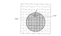
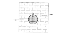
この点について、図11A~図11Cを参照しながら説明する。図11A~図11Cは、フィルタリングする領域と被写体の大きさとの相対的な大きさを比較するための図である。図11Aには、被写体111を近距離から撮影する場合の撮影画像を示し、図11Bには、被写体111を遠距離から撮影する場合の撮影画像を示している。なお、図11A~図11Cにおいて、四角のマス1つ1つは画素を示しており、便宜上、11×11画素で構成される画像を示している。図11Aでは被写体111は大きく写っており、図11Bでは被写体111は小さく写っている。また、図11A、図11Bにおいて、照明光成分算出に用いるフィルタ112のサイズを4×4として図中に点線の枠で示している。
被写体111とフィルタ112の相対的な大きさを比較すると、図11Aでは被写体111の一部をフィルタリングすることになり、図11Bでは被写体111の全体をフィルタリングすることになる。つまり、フィルタサイズが同じ場合、被写体までの距離の増加に伴い、フィルタリングする実空間内の領域も増加する。したがって、照明光成分算出に用いるフィルタサイズを被写体までの距離に応じて小さくしても、実空間内で同じ領域をフィルタリングすることができる。例えば、図11Bにおいては、図11Cに示すフィルタ113のように、フィルタサイズ2×2で、図11Aに示す4×4のフィルタと同等の実空間内での領域をフィルタリングすることができる。上述のように、被写体までの距離に応じて照明光成分算出に用いるフィルタサイズを小さくしても、照明光成分を平滑化するのに十分な実空間内の領域をフィルタリングすることができる。
ここで、図12を参照しながら、被写体までの距離に基づき照明光成分を算出するフィルタのサイズを変更する一例を説明する。フィルタサイズは、例えば、図12のグラフ120で示すように、被写体までの距離の増加に伴い減少させればよい。つまり、注目画素に対応した距離情報が示す被写体までの距離が大きい程、周辺画素として参照する範囲を小さくするようにすればよい。このように、被写体までの距離に応じてフィルタのサイズを小さくすることで、照明光成分を算出する際の計算量を低減する効果も得られる。
また、入力画像の高周波数成分Hも利用することで、更なる画質改善効果が得られる。よって、図3の撮像装置1aでは、H算出部31及びH加算部36を設けている。L圧縮部35において照明光成分Lを圧縮する階調変換処理を施すと、照明光成分Lのエッジ周辺は、照明光成分Lの値が小さい側は明るくなり、照明光成分Lの値が大きい側は明るさを抑えるため、照明光成分Lのエッジ周辺のコントラストは少なからず低下する。
そこで、照明光成分Lを圧縮する階調変換処理を施した画像に、H加算部36が、H算出部31で算出された入力画像の高周波数成分Hを加算することで、照明光成分Lのエッジ周辺のコントラストも高くなり、画質が向上する。
なお、高周波数成分を加算せずとも十分な画質改善効果が得られる。その場合、H加算部36を設けずに、L圧縮部35からの出力値、上述の例で言うと、数式(1)から数式(8)~(10)の処理により照明光成分を圧縮したRGB値を、出力画像として出力すればよい。
また、高周波成分を加算する場合であっても、例えば特許文献1に記載のように拡大してから加算してもよい。ただし、高周波数成分を加算しない場合には、コントラストが低下する領域は照明光成分Lのエッジ周辺であってその他の領域のコントラストは維持されることから、拡大した高周波数成分を足し合わせる場合には、過度にエッジが強調されないように調整を行えば、本発明の効果は十分に得られる。
以上、説明したように、本実施形態によれば、入力画像の照明光成分を、被写体までの距離を考慮して算出し、算出した照明光成分を圧縮し反射光成分を維持する階調変換処理を施すことで、暗部から明部までコントラストが高く、ハローの抑制された画像に変換し、入力画像の高周波成分を加算することで、更にコントラストの高い高画質な画像を得ることができる。
<第2の実施形態>
第1の実施形態では、画像処理を施す画像処理装置を備える撮像装置について述べたが、本発明に係る画像処理装置(図1の画像処理装置10や図3の画像処理装置30)は、図1や図3のように撮像装置内に備えていなくてもよく、例えば、液晶ディスプレイなどの表示装置に備えても、同様の効果は得られる。画像処理装置を表示装置に備える場合、表示装置に入力画像と距離情報が入力され、その画像処理装置で、入力画像に対し第1の実施形態と同様にコントラストが高くハローの抑制された画像に変換する画像処理を施し、表示装置に出力画像を表示する。
第1の実施形態では、画像処理を施す画像処理装置を備える撮像装置について述べたが、本発明に係る画像処理装置(図1の画像処理装置10や図3の画像処理装置30)は、図1や図3のように撮像装置内に備えていなくてもよく、例えば、液晶ディスプレイなどの表示装置に備えても、同様の効果は得られる。画像処理装置を表示装置に備える場合、表示装置に入力画像と距離情報が入力され、その画像処理装置で、入力画像に対し第1の実施形態と同様にコントラストが高くハローの抑制された画像に変換する画像処理を施し、表示装置に出力画像を表示する。
また、左右カメラCL,CRの画像のみが入力され、距離情報が入力されない場合は、表示装置内で左右カメラCL,CRの視差を算出して距離情報とすればよい。また、表示装置に限らず、パーソナルコンピュータ(PC)やブルーレイレコーダなどの映像機器に、本発明に係る画像処理装置を備え、入力画像をコントラストが高くハローの抑制された出力画像に変換してもよい。
<第1、第2の実施形態の構成例>
例えば図1で例示した画像処理装置10における各部11~13、或いは図3で例示した画像処理装置30における各部31~36など、本発明に係る画像処理装置の各構成要素は、例えばマイクロプロセッサ(またはDSP:Digital Signal Processor)、メモリ、バス、インターフェイス、周辺装置などのハードウェアと、これらのハードウェア上にて実行可能なソフトウェアとにより実現できる。上記ハードウェアの一部または全部は集積回路/IC(Integrated Circuit)チップセットとして搭載することができ、その場合、上記ソフトウェアは上記メモリに記憶しておければよい。また、本発明の各構成要素の全てをハードウェアで構成してもよく、その場合についても同様に、そのハードウェアの一部または全部を集積回路/ICチップセットとして搭載することも可能である。
例えば図1で例示した画像処理装置10における各部11~13、或いは図3で例示した画像処理装置30における各部31~36など、本発明に係る画像処理装置の各構成要素は、例えばマイクロプロセッサ(またはDSP:Digital Signal Processor)、メモリ、バス、インターフェイス、周辺装置などのハードウェアと、これらのハードウェア上にて実行可能なソフトウェアとにより実現できる。上記ハードウェアの一部または全部は集積回路/IC(Integrated Circuit)チップセットとして搭載することができ、その場合、上記ソフトウェアは上記メモリに記憶しておければよい。また、本発明の各構成要素の全てをハードウェアで構成してもよく、その場合についても同様に、そのハードウェアの一部または全部を集積回路/ICチップセットとして搭載することも可能である。
また、上述した様々な構成例における機能を実現するためのソフトウェアのプログラムコードを記録した記録媒体を、画像処理装置となる表示装置、PC、レコーダ等の装置に供給し、その装置内のマイクロプロセッサまたはDSPによりプログラムコードが実行されることによっても、本発明の目的が達成される。この場合、ソフトウェアのプログラムコード自体が上述した様々な構成例の機能を実現することになり、このプログラムコード自体や、プログラムコードを記録した記録媒体(外部記録媒体や内部記憶装置)であっても、そのコードを制御側が読み出して実行することで、本発明を構成することができる。外部記録媒体としては、例えばCD、DVD、BDなどの光ディスクやメモリカード等の不揮発性の半導体メモリなど、様々なものが挙げられる。内部記憶装置としては、ハードディスクや半導体メモリなど様々なものが挙げられる。また、プログラムコードはインターネットからダウンロードして実行することや、放送波から受信して実行することもできる。
1,1a…撮像装置、10,30…画像処理装置、11,32…明るさ(Y)算出部、12,34…照明光成分(L)算出部、13,35…照明光成分(L)圧縮部、31…高周波数成分(H)算出部、33…視差算出部、36…高周波数成分(H)加算部、CR…右カメラ、CL…左カメラ、S…シャッタ。
Claims (4)
- 入力画像に対し、注目画素の明るさと周辺画素の明るさから照明光成分を算出し、該照明光成分に基づき階調変換処理を施す画像処理装置であって、
前記照明光成分を、
前記入力画像における被写体までの距離を示す距離情報から算出した前記注目画素に対応した前記距離情報と前記周辺画素に対応した前記距離情報の差異に応じて、明るさに対する重み付けを変え、
かつ、
前記注目画素に対応した前記距離情報に応じて、前記周辺画素として参照する範囲を異ならせて算出する
ことを特徴とする画像処理装置。 - 前記照明光成分を、
前記注目画素に対応した前記距離情報が示す被写体までの距離が大きい程、前記周辺画素として参照する範囲を小さくして算出することを特徴とする請求項1に記載の画像処理装置。 - 前記階調変換処理が施された結果の画像に対して、更に前記入力画像から抽出した高周波数成分を加算することを特徴とする請求項1または2に記載の画像処理装置。
- 請求項1~3のいずれか1項に記載の画像処理装置を備える撮像装置であって、撮影した画像を前記入力画像として前記画像処理装置に入力することを特徴とする撮像装置。
Priority Applications (1)
| Application Number | Priority Date | Filing Date | Title |
|---|---|---|---|
| US14/119,997 US20140146198A1 (en) | 2011-06-08 | 2012-04-25 | Image processing device and image pick-up device |
Applications Claiming Priority (2)
| Application Number | Priority Date | Filing Date | Title |
|---|---|---|---|
| JP2011-128322 | 2011-06-08 | ||
| JP2011128322A JP5781372B2 (ja) | 2011-06-08 | 2011-06-08 | 画像処理装置及び撮像装置 |
Publications (1)
| Publication Number | Publication Date |
|---|---|
| WO2012169292A1 true WO2012169292A1 (ja) | 2012-12-13 |
Family
ID=47295863
Family Applications (1)
| Application Number | Title | Priority Date | Filing Date |
|---|---|---|---|
| PCT/JP2012/061058 Ceased WO2012169292A1 (ja) | 2011-06-08 | 2012-04-25 | 画像処理装置及び撮像装置 |
Country Status (3)
| Country | Link |
|---|---|
| US (1) | US20140146198A1 (ja) |
| JP (1) | JP5781372B2 (ja) |
| WO (1) | WO2012169292A1 (ja) |
Cited By (1)
| Publication number | Priority date | Publication date | Assignee | Title |
|---|---|---|---|---|
| WO2020012938A1 (ja) * | 2018-07-12 | 2020-01-16 | 株式会社ジャパンディスプレイ | 表示装置 |
Families Citing this family (8)
| Publication number | Priority date | Publication date | Assignee | Title |
|---|---|---|---|---|
| EP2564373B1 (en) * | 2010-04-26 | 2014-12-17 | Robert Bosch GmbH | Detection and/or enhancement of contrast differences in digital image data |
| US10169909B2 (en) * | 2014-08-07 | 2019-01-01 | Pixar | Generating a volumetric projection for an object |
| JP6690125B2 (ja) * | 2015-03-19 | 2020-04-28 | 富士ゼロックス株式会社 | 画像処理装置及びプログラム |
| WO2017085786A1 (ja) * | 2015-11-17 | 2017-05-26 | Eizo株式会社 | 画像変換方法及び装置 |
| KR102644946B1 (ko) * | 2019-05-02 | 2024-03-08 | 삼성전자주식회사 | 영상 처리 방법 및 장치 |
| JP7342517B2 (ja) * | 2019-08-21 | 2023-09-12 | 富士通株式会社 | 画像処理装置、方法、及びプログラム |
| WO2023026407A1 (ja) * | 2021-08-25 | 2023-03-02 | 株式会社ソシオネクスト | 画像処理装置、画像処理方法および画像処理プログラム |
| CN114038440B (zh) * | 2021-11-30 | 2023-04-07 | 京东方科技集团股份有限公司 | 显示装置及其控制方法 |
Citations (3)
| Publication number | Priority date | Publication date | Assignee | Title |
|---|---|---|---|---|
| JP2007281767A (ja) * | 2006-04-05 | 2007-10-25 | Fujitsu Ltd | 画像処理装置、画像処理プログラムおよび画像処理方法 |
| JP2010239492A (ja) * | 2009-03-31 | 2010-10-21 | Olympus Corp | 撮像装置および映像信号のノイズ低減方法 |
| JP2010239493A (ja) * | 2009-03-31 | 2010-10-21 | Olympus Corp | 撮像装置および映像信号の補正処理方法 |
Family Cites Families (4)
| Publication number | Priority date | Publication date | Assignee | Title |
|---|---|---|---|---|
| US5049997A (en) * | 1989-04-10 | 1991-09-17 | Fuji Photo Film Co., Ltd. | Video camera exposure control method and apparatus for preventing improper exposure due to changing object size or displacement and luminance difference between the object and background |
| US7683964B2 (en) * | 2005-09-05 | 2010-03-23 | Sony Corporation | Image capturing apparatus and image capturing method |
| JP4872277B2 (ja) * | 2005-09-05 | 2012-02-08 | ソニー株式会社 | 撮像装置および撮像方法 |
| KR101313637B1 (ko) * | 2006-06-09 | 2013-10-02 | 서강대학교산학협력단 | 콘트라스트 개선을 위한 영상 처리 장치 및 영상 처리 방법 |
-
2011
- 2011-06-08 JP JP2011128322A patent/JP5781372B2/ja not_active Expired - Fee Related
-
2012
- 2012-04-25 WO PCT/JP2012/061058 patent/WO2012169292A1/ja not_active Ceased
- 2012-04-25 US US14/119,997 patent/US20140146198A1/en not_active Abandoned
Patent Citations (3)
| Publication number | Priority date | Publication date | Assignee | Title |
|---|---|---|---|---|
| JP2007281767A (ja) * | 2006-04-05 | 2007-10-25 | Fujitsu Ltd | 画像処理装置、画像処理プログラムおよび画像処理方法 |
| JP2010239492A (ja) * | 2009-03-31 | 2010-10-21 | Olympus Corp | 撮像装置および映像信号のノイズ低減方法 |
| JP2010239493A (ja) * | 2009-03-31 | 2010-10-21 | Olympus Corp | 撮像装置および映像信号の補正処理方法 |
Cited By (3)
| Publication number | Priority date | Publication date | Assignee | Title |
|---|---|---|---|---|
| WO2020012938A1 (ja) * | 2018-07-12 | 2020-01-16 | 株式会社ジャパンディスプレイ | 表示装置 |
| JP2020008812A (ja) * | 2018-07-12 | 2020-01-16 | 株式会社ジャパンディスプレイ | 表示装置 |
| JP7240828B2 (ja) | 2018-07-12 | 2023-03-16 | 株式会社ジャパンディスプレイ | 表示装置 |
Also Published As
| Publication number | Publication date |
|---|---|
| US20140146198A1 (en) | 2014-05-29 |
| JP2012256168A (ja) | 2012-12-27 |
| JP5781372B2 (ja) | 2015-09-24 |
Similar Documents
| Publication | Publication Date | Title |
|---|---|---|
| JP5781372B2 (ja) | 画像処理装置及び撮像装置 | |
| CN110022469B (zh) | 图像处理方法、装置、存储介质及电子设备 | |
| CN103854259B (zh) | 图像处理设备以及处理图像的方法 | |
| US10298853B2 (en) | Image processing apparatus, method of controlling image processing apparatus, and imaging apparatus | |
| US11328679B2 (en) | Image processing apparatus, control method thereof, and non-transitory computer-readable storage medium | |
| US9113059B2 (en) | Image pickup apparatus and image region discrimination method | |
| CN103248809B (zh) | 图像信号处理装置、摄像装置以及图像处理装置 | |
| KR102049080B1 (ko) | 영상 처리 장치 및 방법 | |
| JP6833415B2 (ja) | 画像処理装置、画像処理方法、及びプログラム | |
| JP6711396B2 (ja) | 画像処理装置、撮像装置、および画像処理方法、並びにプログラム | |
| CN105049680A (zh) | 进行图像恢复处理的图像处理设备和图像处理方法 | |
| WO2005101309A1 (en) | Methods and systems for converting images from low dynamic range to high dynamic range | |
| JP5887303B2 (ja) | 画像信号処理装置,撮像装置および画像処理プログラム | |
| US9961319B2 (en) | Image processing apparatus and control method thereof | |
| JP6818463B2 (ja) | 画像処理装置、画像処理方法及びプログラム | |
| US10755399B2 (en) | Image processing device, image processing method, and image processing program | |
| JP2010220207A (ja) | 画像処理装置及び画像処理プログラム | |
| JP5907590B2 (ja) | 画像処理装置、画像処理方法およびプログラム | |
| JP6624785B2 (ja) | 画像処理方法、画像処理装置、撮像装置、プログラム、および、記憶媒体 | |
| JP2008305122A (ja) | 画像処理装置、画像処理方法、およびプログラム | |
| KR20120122574A (ko) | 디지털 카메라 장치에서 영상 처리 장치 및 방법 | |
| Choudhury et al. | Perceptually motivated automatic color contrast enhancement | |
| US9055232B2 (en) | Image processing apparatus capable of adding soft focus effects, image processing method, and storage medium | |
| JP5178421B2 (ja) | 画像処理装置、画像処理方法及び撮像装置 | |
| JP2017182668A (ja) | データ処理装置、撮像装置、及びデータ処理方法 |
Legal Events
| Date | Code | Title | Description |
|---|---|---|---|
| 121 | Ep: the epo has been informed by wipo that ep was designated in this application |
Ref document number: 12796123 Country of ref document: EP Kind code of ref document: A1 |
|
| WWE | Wipo information: entry into national phase |
Ref document number: 14119997 Country of ref document: US |
|
| NENP | Non-entry into the national phase |
Ref country code: DE |
|
| 122 | Ep: pct application non-entry in european phase |
Ref document number: 12796123 Country of ref document: EP Kind code of ref document: A1 |