WO2012157121A1 - 車両用表示装置及び運転支援装置 - Google Patents
車両用表示装置及び運転支援装置 Download PDFInfo
- Publication number
- WO2012157121A1 WO2012157121A1 PCT/JP2011/061567 JP2011061567W WO2012157121A1 WO 2012157121 A1 WO2012157121 A1 WO 2012157121A1 JP 2011061567 W JP2011061567 W JP 2011061567W WO 2012157121 A1 WO2012157121 A1 WO 2012157121A1
- Authority
- WO
- WIPO (PCT)
- Prior art keywords
- vehicle
- display
- information
- driver
- change
- Prior art date
- Legal status (The legal status is an assumption and is not a legal conclusion. Google has not performed a legal analysis and makes no representation as to the accuracy of the status listed.)
- Ceased
Links
Images





Classifications
-
- B—PERFORMING OPERATIONS; TRANSPORTING
- B60—VEHICLES IN GENERAL
- B60R—VEHICLES, VEHICLE FITTINGS, OR VEHICLE PARTS, NOT OTHERWISE PROVIDED FOR
- B60R16/00—Electric or fluid circuits specially adapted for vehicles and not otherwise provided for; Arrangement of elements of electric or fluid circuits specially adapted for vehicles and not otherwise provided for
- B60R16/02—Electric or fluid circuits specially adapted for vehicles and not otherwise provided for; Arrangement of elements of electric or fluid circuits specially adapted for vehicles and not otherwise provided for electric constitutive elements
- B60R16/023—Electric or fluid circuits specially adapted for vehicles and not otherwise provided for; Arrangement of elements of electric or fluid circuits specially adapted for vehicles and not otherwise provided for electric constitutive elements for transmission of signals between vehicle parts or subsystems
- B60R16/0231—Circuits relating to the driving or the functioning of the vehicle
- B60R16/0236—Circuits relating to the driving or the functioning of the vehicle for economical driving
-
- B—PERFORMING OPERATIONS; TRANSPORTING
- B60—VEHICLES IN GENERAL
- B60K—ARRANGEMENT OR MOUNTING OF PROPULSION UNITS OR OF TRANSMISSIONS IN VEHICLES; ARRANGEMENT OR MOUNTING OF PLURAL DIVERSE PRIME-MOVERS IN VEHICLES; AUXILIARY DRIVES FOR VEHICLES; INSTRUMENTATION OR DASHBOARDS FOR VEHICLES; ARRANGEMENTS IN CONNECTION WITH COOLING, AIR INTAKE, GAS EXHAUST OR FUEL SUPPLY OF PROPULSION UNITS IN VEHICLES
- B60K35/00—Instruments specially adapted for vehicles; Arrangement of instruments in or on vehicles
- B60K35/20—Output arrangements, i.e. from vehicle to user, associated with vehicle functions or specially adapted therefor
- B60K35/21—Output arrangements, i.e. from vehicle to user, associated with vehicle functions or specially adapted therefor using visual output, e.g. blinking lights or matrix displays
- B60K35/22—Display screens
-
- B—PERFORMING OPERATIONS; TRANSPORTING
- B60—VEHICLES IN GENERAL
- B60K—ARRANGEMENT OR MOUNTING OF PROPULSION UNITS OR OF TRANSMISSIONS IN VEHICLES; ARRANGEMENT OR MOUNTING OF PLURAL DIVERSE PRIME-MOVERS IN VEHICLES; AUXILIARY DRIVES FOR VEHICLES; INSTRUMENTATION OR DASHBOARDS FOR VEHICLES; ARRANGEMENTS IN CONNECTION WITH COOLING, AIR INTAKE, GAS EXHAUST OR FUEL SUPPLY OF PROPULSION UNITS IN VEHICLES
- B60K35/00—Instruments specially adapted for vehicles; Arrangement of instruments in or on vehicles
- B60K35/20—Output arrangements, i.e. from vehicle to user, associated with vehicle functions or specially adapted therefor
- B60K35/28—Output arrangements, i.e. from vehicle to user, associated with vehicle functions or specially adapted therefor characterised by the type of the output information, e.g. video entertainment or vehicle dynamics information; characterised by the purpose of the output information, e.g. for attracting the attention of the driver
-
- B—PERFORMING OPERATIONS; TRANSPORTING
- B60—VEHICLES IN GENERAL
- B60K—ARRANGEMENT OR MOUNTING OF PROPULSION UNITS OR OF TRANSMISSIONS IN VEHICLES; ARRANGEMENT OR MOUNTING OF PLURAL DIVERSE PRIME-MOVERS IN VEHICLES; AUXILIARY DRIVES FOR VEHICLES; INSTRUMENTATION OR DASHBOARDS FOR VEHICLES; ARRANGEMENTS IN CONNECTION WITH COOLING, AIR INTAKE, GAS EXHAUST OR FUEL SUPPLY OF PROPULSION UNITS IN VEHICLES
- B60K35/00—Instruments specially adapted for vehicles; Arrangement of instruments in or on vehicles
- B60K35/80—Arrangements for controlling instruments
- B60K35/81—Arrangements for controlling instruments for controlling displays
-
- B—PERFORMING OPERATIONS; TRANSPORTING
- B60—VEHICLES IN GENERAL
- B60W—CONJOINT CONTROL OF VEHICLE SUB-UNITS OF DIFFERENT TYPE OR DIFFERENT FUNCTION; CONTROL SYSTEMS SPECIALLY ADAPTED FOR HYBRID VEHICLES; ROAD VEHICLE DRIVE CONTROL SYSTEMS FOR PURPOSES NOT RELATED TO THE CONTROL OF A PARTICULAR SUB-UNIT
- B60W50/00—Details of control systems for road vehicle drive control not related to the control of a particular sub-unit, e.g. process diagnostic or vehicle driver interfaces
- B60W50/08—Interaction between the driver and the control system
- B60W50/14—Means for informing the driver, warning the driver or prompting a driver intervention
-
- B—PERFORMING OPERATIONS; TRANSPORTING
- B60—VEHICLES IN GENERAL
- B60K—ARRANGEMENT OR MOUNTING OF PROPULSION UNITS OR OF TRANSMISSIONS IN VEHICLES; ARRANGEMENT OR MOUNTING OF PLURAL DIVERSE PRIME-MOVERS IN VEHICLES; AUXILIARY DRIVES FOR VEHICLES; INSTRUMENTATION OR DASHBOARDS FOR VEHICLES; ARRANGEMENTS IN CONNECTION WITH COOLING, AIR INTAKE, GAS EXHAUST OR FUEL SUPPLY OF PROPULSION UNITS IN VEHICLES
- B60K2360/00—Indexing scheme associated with groups B60K35/00 or B60K37/00 relating to details of instruments or dashboards
- B60K2360/16—Type of output information
- B60K2360/174—Economic driving
-
- B—PERFORMING OPERATIONS; TRANSPORTING
- B60—VEHICLES IN GENERAL
- B60W—CONJOINT CONTROL OF VEHICLE SUB-UNITS OF DIFFERENT TYPE OR DIFFERENT FUNCTION; CONTROL SYSTEMS SPECIALLY ADAPTED FOR HYBRID VEHICLES; ROAD VEHICLE DRIVE CONTROL SYSTEMS FOR PURPOSES NOT RELATED TO THE CONTROL OF A PARTICULAR SUB-UNIT
- B60W50/00—Details of control systems for road vehicle drive control not related to the control of a particular sub-unit, e.g. process diagnostic or vehicle driver interfaces
- B60W50/08—Interaction between the driver and the control system
- B60W50/14—Means for informing the driver, warning the driver or prompting a driver intervention
- B60W2050/146—Display means
-
- B—PERFORMING OPERATIONS; TRANSPORTING
- B60—VEHICLES IN GENERAL
- B60W—CONJOINT CONTROL OF VEHICLE SUB-UNITS OF DIFFERENT TYPE OR DIFFERENT FUNCTION; CONTROL SYSTEMS SPECIALLY ADAPTED FOR HYBRID VEHICLES; ROAD VEHICLE DRIVE CONTROL SYSTEMS FOR PURPOSES NOT RELATED TO THE CONTROL OF A PARTICULAR SUB-UNIT
- B60W2510/00—Input parameters relating to a particular sub-units
- B60W2510/24—Energy storage means
- B60W2510/242—Energy storage means for electrical energy
- B60W2510/244—Charge state
-
- Y—GENERAL TAGGING OF NEW TECHNOLOGICAL DEVELOPMENTS; GENERAL TAGGING OF CROSS-SECTIONAL TECHNOLOGIES SPANNING OVER SEVERAL SECTIONS OF THE IPC; TECHNICAL SUBJECTS COVERED BY FORMER USPC CROSS-REFERENCE ART COLLECTIONS [XRACs] AND DIGESTS
- Y02—TECHNOLOGIES OR APPLICATIONS FOR MITIGATION OR ADAPTATION AGAINST CLIMATE CHANGE
- Y02T—CLIMATE CHANGE MITIGATION TECHNOLOGIES RELATED TO TRANSPORTATION
- Y02T10/00—Road transport of goods or passengers
- Y02T10/80—Technologies aiming to reduce greenhouse gasses emissions common to all road transportation technologies
- Y02T10/84—Data processing systems or methods, management, administration
Definitions
- the present invention relates to a vehicle display device that presents information related to vehicle operation to a driver, and a driving support device including the vehicle display device.
- a vehicle such as an automobile is provided with an instrument panel composed of various instruments such as a speedometer that displays the speed of the vehicle and a rotational speedometer that displays the rotational speed of an engine mounted on the vehicle.
- a speedometer that displays the speed of the vehicle
- a rotational speedometer that displays the rotational speed of an engine mounted on the vehicle.
- the driver (driver) of a vehicle can grasp
- eco-drive fuel-saving driving
- This eco-drive indicator is provided, for example, in the central portion of a tachometer provided on the instrument panel, as shown as a region 8B in FIG. 9A.
- the eco-drive indicator is provided with a display area 10 indicating the range of the accelerator opening, and the gauge 11 that is the display content of the display area 10 is It changes with the depression amount of the accelerator pedal by the driver of the vehicle.
- the display area 10 has a low fuel consumption per unit time, that is, an area 12 indicating the accelerator opening that can realize a highly economical vehicle operation, and conversely, the fuel consumption per unit time is large. Therefore, it is comprised from two area
- an eco-drive indicator for example, when the gauge 11 indicating the accelerator opening range is in the region 12 where the highly economical vehicle operation can be realized, for example, “Economy” is displayed on the display screen of the eco-drive indicator.
- the abbreviated “ECO” character 14 is lit up.
- the eco-drive indicator visually displays the driver with the gauge 11 as to whether or not the accelerator opening having a high correlation with the fuel consumption is in a highly economical state, thereby enabling highly economical vehicle operation. The driver is prompted.
- a sudden accelerator operation in other words, an accelerator operation with a large amount of change per unit time is a main factor that reduces the economics of vehicle operation.
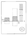
- the amount of change in the accelerator opening per unit time is displayed visually. That is, as shown in FIG. 10 of the present application, in the vehicle display device described in Patent Document 1, the time change rate and the average value of the accelerator operation amount are visually displayed by bar graph-like bar lines 32 and 34, respectively.
- the bars 32 and 34 representing the time change rate of the accelerator operation amount and the average value thereof extend upward with respect to the scale 0.
- the bar lines 32 and 34 representing the time change rate of the accelerator operation amount and the average value thereof extend downward with respect to the scale 0.
- the characters “ECO” indicating that a highly economical vehicle operation is being performed are lit in the area.
- the vehicular display device disclosed in Patent Document 1 performs a rapid accelerator operation that directly leads to an increase in fuel consumption, that is, a decrease in economy, along with whether or not a highly economical vehicle operation is being performed. This makes it possible to present to the driver whether or not the vehicle has been dismissed, and thus to effectively encourage the driver to operate the vehicle with high economic efficiency.
- the present invention has been made in view of such circumstances, and an object of the present invention is to provide a vehicle display device capable of efficiently displaying two or more information related to vehicle operation while suppressing a decrease in visibility, and An object of the present invention is to provide a driving support device capable of supporting vehicle operation using the vehicle display device.
- a display device for a vehicle is a display device for a vehicle including a display unit that visually displays information related to operation of the vehicle, and a display control unit that controls a display mode of the display unit.
- the gist is that the display control unit collectively displays information indicating an operation amount based on a vehicle operation and information prompting the driver to change the vehicle operation in a common display area of the display unit in an identifiable manner. .
- the information indicating the amount of operation based on the vehicle operation and the information prompting the driver to change the vehicle operation are collectively displayed in a common area of the display unit in an identifiable manner through the control by the display control unit. . That is, through the control by the display control unit, for example, in normal times, the display unit displays only information indicating the operation amount based on the vehicle operation, and it is necessary to guide the driver to change the vehicle operation from the viewpoint of various driving assistances. When this occurs, the display unit displays information for prompting the change of the vehicle operation. For this reason, it becomes possible to present to the driver of a vehicle two information, the information which shows the operation amount based on vehicle operation, and the information which prompts the driver to change vehicle operation via one display part. As a result, it is possible to efficiently display two or more pieces of information regarding the vehicle operation while suppressing a decrease in visibility.
- the information indicating the amount of operation based on the vehicle operation and the information prompting the driver to change the vehicle operation include, for example, information indicating the amount of depression of the accelerator pedal and the amount of depression of the accelerator pedal according to the surrounding environment of the vehicle. It is possible to display information having a strong correlation with each other, such as information for guiding the driver to the driver or the increasing operation. For this reason, by displaying such two pieces of highly correlated information in a collective manner so that one display unit can identify the vehicle information, the driver of the vehicle can monitor the operation amount based on his own vehicle operation by the display unit, When this change occurs, it is possible to change the vehicle operation according to the information displayed on the display unit being monitored. As a result, the driver can instantly confirm not only the amount of operation based on the vehicle operation but also the need to change the vehicle operation, by simply viewing a single display unit on which two pieces of highly correlated information are collectively displayed. It is also possible to do.
- the information indicating the operation amount based on the vehicle operation is displayed as a display ratio in the display area of the display unit, and the information for prompting the change of the vehicle operation is the operation amount based on the vehicle operation.
- the same display unit in a manner different from each other and different from each other.
- the information indicating the operation amount based on the vehicle operation is expressed as a display ratio in the display area of the display unit, for example, a display length, a display area, or an operation amount that is proportional to the operation amount.
- Information is displayed on the display unit. That is, the amount of operation based on the vehicle operation changes depending on the surrounding environment of the vehicle, such as the amount of depression of an accelerator pedal or a brake pedal. For example, the larger the amount of operation, the proportion of the display area occupied by the display unit Is displayed larger, and the smaller the operation amount, the smaller the proportion of the display area occupied by the display area.
- the information prompting the change of the vehicle operation is displayed on the display unit in a manner that overlaps with the information indicating the operation amount based on the vehicle operation and is different from each other. Therefore, when the display unit displays two pieces of information indicating different contents from each other, for example, information for prompting a change in vehicle operation and information indicating an operation amount based on the vehicle operation are subdivided into one display region. It is not displayed. Therefore, the simultaneous display property of the information for prompting the change of the vehicle operation and the information indicating the operation amount based on the vehicle operation can be improved.
- the display of the information prompting the change of the vehicle operation which is overlapped with the information indicating the operation amount based on the vehicle operation and is different from each other, is a change in the lamp color of the display unit. .
- the display unit displays information that prompts a change in vehicle operation through a change in lamp color as in the above configuration, for example, when a highly economical vehicle operation is performed by a driver, the information is based on the vehicle operation.
- Information indicating the operation amount is displayed in a lamp color, for example, in “green”.
- the lamp color of the display unit is changed from, for example, “green” to “red”, for example, an accelerator pedal It is possible to prompt the driver to turn off the brake pedal or to regenerate the brake.
- the display unit can simultaneously display the information indicating the operation amount based on the vehicle operation based on the display ratio in the display area of the display unit, and simultaneously prompting the user to change the vehicle operation through the change of the lamp color. It becomes possible. Therefore, the display unit can simultaneously present information indicating the operation amount based on the vehicle operation and information prompting the change of the vehicle operation to the driver of the vehicle through the change of the display mode.
- the display of the information urging the change of the vehicle operation in the form overlapping with the information indicating the operation amount based on the vehicle operation and different from each other is execution of the blinking display of the display unit.
- the display unit displays information prompting the change of the vehicle operation through the change of the lighting state as in the above configuration, for example, when a highly economical vehicle operation is performed by the driver, the information is based on the vehicle operation. Information indicating the operation amount is always lit on the display unit. On the other hand, for example, when the economics of vehicle operation is reduced due to changes in traffic conditions around the vehicle, the display format of the information indicating the operation amount that is always lit and displayed is changed to flashing display, For example, the display unit can prompt the driver to turn off the accelerator pedal or to regenerate the brake.
- the display unit can simultaneously display information indicating the amount of operation based on the vehicle operation based on the display ratio in the display area of the display unit, while prompting the user to change the vehicle operation through the change of the lighting mode. It becomes possible. Therefore, the display unit can simultaneously present information indicating the operation amount based on the vehicle operation and information prompting the change of the vehicle operation to the driver of the vehicle through the change of the display mode.
- information that prompts a change in the vehicle operation is displayed in a manner that overlaps with the information indicating the operation amount based on the vehicle operation and that is different from each other, by changing the transmittance or luminance of the display unit. It is.
- the display unit displays information prompting the change of the vehicle operation through the change of the lighting state as in the above configuration, for example, when a highly economical vehicle operation is performed by the driver, the information is based on the vehicle operation.
- Information indicating the operation amount is lit and displayed by the display unit based on a predetermined transmittance and luminance.
- the information indicating the operation amount is highlighted and displayed by the display unit, so that, for example, the accelerator pedal is depressed or the brake regeneration is performed. It is possible to prompt the driver.
- the display unit can display information indicating the operation amount based on the vehicle operation based on the display ratio in the display area of the display unit, and at the same time, the information prompting the change of the vehicle operation through the change in the transmittance and the luminance. It is possible to display. Therefore, the display unit can simultaneously present information indicating the operation amount based on the vehicle operation and information prompting the change of the vehicle operation to the driver of the vehicle through the change of the display mode.
- the display unit displays, as an area for displaying information indicating an operation amount based on the vehicle operation, a first area for displaying information indicating an operation amount for realizing a highly economical vehicle operation; A second region for displaying an operation amount based on a vehicle operation other than a highly economical vehicle operation, wherein the display control unit displays the information for prompting a change in the vehicle operation.
- the information indicating the operation amount based on is displayed across both the first area and the second area.
- the information indicating the operation amount based on the vehicle operation includes the first region displaying information indicating the operation amount for realizing the highly economical vehicle operation, and the vehicle operation other than the highly economical vehicle operation.
- the display unit uses a total of two areas including a second area for displaying the operation amount based on the. That is, for example, when a highly economical vehicle operation is performed by the driver, information indicating the operation amount based on the vehicle operation is displayed within the range of the first region.
- the operation amount based on the vehicle operation is constant and the information indicating the operation amount based on the vehicle operation may be displayed only in the first area.
- the operation amount based on the vehicle operation is within a predetermined range and is in a highly economical state, it is based on the vehicle operation in accordance with a change in traffic conditions around the vehicle.
- information indicating the operation amount based on the vehicle operation is displayed across both the first and second regions in the display unit.
- the display unit can prompt the vehicle driver to change the vehicle operation such as changing the accelerator pedal from the on state to the off state.
- the display unit can display information that prompts the user to change the vehicle operation by using the first and second display areas. Therefore, through such a change in the display mode, it is possible to present information indicating the operation amount based on the vehicle operation and information prompting the change in the vehicle operation to the driver of the vehicle through one display unit. .
- the display unit when the display unit displays the depression amount of the accelerator pedal or the depression amount of the brake pedal as information indicating the operation amount based on the vehicle operation, the display unit urges deceleration of the vehicle as a change in the vehicle operation. In this case, even when the operation amount based on the vehicle operation by the driver is constant, information indicating the operation amount is displayed across both the first and second regions. Therefore, based on the traffic conditions around the vehicle, the display unit can easily recognize that the accelerator pedal is excessively depressed or the brake pedal is insufficiently depressed. It is also possible.
- the information indicating the operation amount based on the vehicle operation is information indicating an accelerator opening degree of the vehicle by the driver, and the information prompting the change of the vehicle operation approaches a stop position or a deceleration position. This is information that prompts the vehicle to decelerate.
- information indicating the accelerator opening degree of the vehicle by the driver is displayed on the display unit as information indicating the operation amount based on the vehicle operation.
- information that prompts the vehicle to approach a stop position or a deceleration position such as an intersection or a temporary stop position is displayed on the display unit as information that prompts a change in vehicle operation.
- the information prompting the deceleration is the information indicating the accelerator opening.
- the information indicating the accelerator opening is collectively displayed on the display unit in a distinguishable manner.
- a driving support device includes a display unit that visually displays information related to operation of the vehicle, and a display control unit that controls the display mode of the display unit.
- the vehicle display device is provided, and driving assistance is provided through the presentation of information through the vehicle display device.
- the vehicle display device includes the vehicle display device described above.
- the present invention is particularly effective when applied to a driving support device including the above-described vehicle display device.
- the display unit of the vehicle display device displays information related to the vehicle operation, and also changes the vehicle operation when it is necessary to change the vehicle operation from the viewpoint of various driving assistances. Present the prompting information to the driver.
- effective vehicle operation support can be achieved through the use of a vehicle display device that can efficiently display two or more information related to vehicle operation while suppressing a decrease in visibility.
- the driving support apparatus further includes a prediction unit that predicts a vehicle operation of the driver, and the display control unit is configured to predict the vehicle stop operation or the deceleration operation by the prediction unit.
- Information for prompting deceleration of the vehicle is displayed on the display unit as information for prompting a change in operation.
- the prediction unit predicts a stop operation or a deceleration operation of the vehicle, in other words, predicts whether the vehicle is approaching a position where the stop operation or the deceleration operation is required. Then, when a vehicle stop operation or a deceleration operation is predicted by the prediction unit, information that prompts the vehicle to decelerate is displayed on the display unit as information that prompts a change in the vehicle operation. For this reason, even if the driver does not recognize the presence of a traffic element that requires a deceleration operation or a stop operation in front of the traveling direction of the vehicle, the deceleration operation or the stop is performed through the prediction by the prediction unit.
- the driving support device can make the driver of the vehicle heading toward the deceleration position or stop position recognize in advance the existence of the deceleration position or stop position, and prompt the driver to perform a gentle deceleration operation with a margin. It becomes possible. In addition, since the driver is prompted to perform a slow deceleration operation with a margin as described above, it is possible to improve the economical efficiency of the vehicle operation.
- the prediction unit includes a learning unit that learns a vehicle operation by the driver, and predicts a driver's vehicle operation based on a learning result by the learning unit.
- the learning unit appropriately learns a point where a deceleration operation or a stop operation is performed by the driver through learning a vehicle operation by the driver. For this reason, for example, the prediction unit can identify the point where the deceleration operation or the stop operation is necessary based on the behavior history of the vehicle that is the target of driving assistance by associating the learning result with the map data or the like. Become. As a result, the prediction unit can perform prediction along actual road conditions based on learning of vehicle operation performed under actual road conditions.
- the prediction unit is based on traffic information acquired through at least one of road-to-vehicle communication, vehicle-to-vehicle communication, and road map data registered in a car navigation system. Predict vehicle operation.
- roadside communication devices are often provided in traffic elements such as traffic lights and intersections.
- the vehicle can acquire information related to the signal cycle, the distance from the vehicle to the traffic light, and the like.
- the road map data registered in advance in the car navigation system also stores information such as the latitude and longitude of traffic elements such as intersections and traffic lights, and the vehicle can be decelerated and stopped even when the road map data is referenced.
- the prediction unit acquires traffic information through at least one of road-to-vehicle communication, vehicle-to-vehicle communication, and road map data registered in the car navigation system, as described above, and acquires the traffic information. If the driver's vehicle operation is predicted based on the traffic information, it is possible to grasp the existence of a traffic element that requires a deceleration operation, a stop operation, or the like by using these existing systems. That is, the prediction unit can predict whether or not a deceleration operation or the like is performed by the driver using an existing system.
- the driving support apparatus further includes an operation information detection unit that detects a vehicle operation of a driver, and the display control unit predicts whether the vehicle is decelerating or stopping by the prediction unit.
- the operation information detecting unit detects that the driver depresses the accelerator pedal, the information for prompting the vehicle to be decelerated is displayed on the display unit as information for prompting the change of the vehicle operation.
- the prediction unit When a vehicle deceleration operation or a stop operation is predicted by the prediction unit, for example, based on the traffic information acquired through the road-to-vehicle communication, the indication of the traffic light existing ahead in the vehicle traveling direction is “blue” ( In spite of being predicted to change from “green” to “red”, when the driver is stepping on the accelerator pedal, it is particularly necessary to prompt the driver to perform a deceleration operation. That is, in this case, the display unit displays information that prompts the vehicle to decelerate, so that it is possible to guide the driver to stop the depression of the accelerator pedal or start the depression of the brake pedal, for example.
- the display unit displays, for example, information for inducing accelerator turn-off or information for executing brake regeneration as information for prompting a change in vehicle operation, not only smooth deceleration operation and stop operation can be realized. In addition, a highly economical vehicle operation is also realized.
- FIG. 1 is a schematic diagram of a vehicle in which the vehicle display device and the driving support device are suitable for a first embodiment in which the vehicle display device according to the present invention and a driving support device using the vehicle display device are embodied.
- the block diagram which shows a structure.
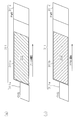
- (A) is a figure which shows the example of a display of the information which shows the operation amount based on the vehicle operation by a display part.
- (B) is a figure which shows the example of a display of the information which shows the operation amount based on the vehicle operation by a display part, and the information which prompts the change of vehicle operation.
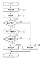
- the flowchart which shows the example about the control procedure of the display mode by the display apparatus for vehicles of the embodiment.
- (A) is a figure which shows an example of the relationship between the vehicle made into the object of driving assistance, and the driving environment of the vehicle.
- (B) is a time chart which shows an example of the signal cycle of a traffic light.
- (C) is a time chart showing an example of the transition of the gauge light color displayed on the display unit.
- (D) is a time chart which shows an example of the speed transition of the vehicle made into the object of driving assistance.
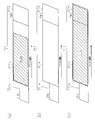
- (A) shows the operation amount based on the vehicle operation by a display part about 2nd Embodiment which actualized the display apparatus for vehicles concerning this invention, and the driving assistance apparatus using this display device for vehicles. The figure which shows the example of a display of information.
- (B) is a figure which shows the example of a display of the information which shows the operation amount based on the vehicle operation by a display part, and the information which prompts the change of vehicle operation when deceleration assistance is not performed.
- (C) is a figure which shows the example of a display of the information which shows the operation amount based on the vehicle operation by a display part, and the information which prompts the change of a vehicle operation when deceleration assistance is performed.
- the flowchart which shows the example about the control procedure of the display mode by the display apparatus for vehicles of the embodiment.
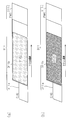
- (A) shows the amount of operation based on the vehicle operation by a display part about 3rd Embodiment which actualized the display apparatus for vehicles concerning this invention, and the driving assistance apparatus using this display apparatus for vehicles.
- the figure which shows the example of a display of information is a figure which shows the example of a display of the information which shows the operation amount based on the vehicle operation by a display part, and the information which prompts the change of vehicle operation.
- A shows the operation amount based on the vehicle operation by a display part about 4th Embodiment which actualized the display apparatus for vehicles concerning this invention, and the driving assistance apparatus using this display device for vehicles.
- (B) is a figure which shows the example of a display of the information which shows the operation amount based on the vehicle operation by a display part, and the information which prompts the change of vehicle operation.
- B) is an enlarged view showing an example of the eco-drive indicator.
- the vehicle display device according to the present embodiment is mounted on, for example, a hybrid vehicle, and is incorporated into an instrument panel provided in the vehicle interior as illustrated in FIG.
- an operation information detection unit 110 that detects a vehicle operation by a driver of the vehicle C is mounted on the vehicle C to which the vehicle display device and the driving support device of the present embodiment are applied.
- the operation information detection unit 110 detects, for example, the vehicle speed sensor 111 that detects the traveling speed of the vehicle C, the accelerator sensor 112 that detects the amount of depression of the accelerator pedal by the driver (driver) of the vehicle C, and the absolute position of the vehicle C.
- the GPS 113 is configured.
- the vehicle speed sensor 111 detects the rotational speed of the wheel of the vehicle C, and outputs a signal corresponding to the detected rotational speed to the driving support device 200 that executes various driving support to the driver of the vehicle C. .
- the accelerator sensor 112 detects the accelerator opening that is changed by the operation of the accelerator pedal by the driver of the vehicle C, and outputs a signal corresponding to the detected accelerator opening to the driving support device 200.
- the GPS 113 receives a GPS satellite signal for detecting the absolute position of the vehicle, and detects the position of the vehicle based on the received GPS satellite signal. And GPS113 outputs the information which shows the latitude longitude which shows the position of the detected vehicle to the driving assistance apparatus 200.
- FIG. In the present embodiment, for example, the detection result of the accelerator sensor 112 is displayed on the vehicle display device 300 in order to visually display the operation amount based on the vehicle operation by the driver on the vehicle display device 300 provided in the instrument panel. It is designed to be entered.
- the vehicle C is equipped with an infrastructure communication device 120 that realizes road-to-vehicle communication.
- the infrastructure communication device 120 is a communication device that communicates with an optical beacon antenna 121 provided on a road by an optical signal such as infrared rays or wirelessly communicates with another vehicle having a wireless communication function.
- the optical beacon antenna 121 is installed on the road at a position several hundred meters in front of an intersection where a traffic light is provided, for example.
- the optical beacon antenna 121 transmits information such as a distance to the intersection, a signal cycle of a traffic light provided at the intersection, road alignment, and the like as an infrastructure information signal.
- the infrastructure communication device 120 receives the infrastructure information signal transmitted from the optical beacon antenna 121 and outputs the received infrastructure information signal to the driving support device 200.
- the infrastructure information signal includes road conditions such as intersection shape, curvature, gradient, number of lanes, etc. of the road where the optical beacon antenna 121 is provided, surrounding information detected by roadside incidental information, ground facilities, etc.
- the mobile body information such as other vehicles is also included.
- the infrastructure communication device 120 receives road traffic information distributed from the VICS (registered trademark) center via the optical beacon antenna 121.
- the road traffic information includes, for example, traffic jam information such as a traffic jam section and a traffic jam degree, traffic regulation information such as a traffic stop.
- the car navigation system 130 is mounted on the vehicle C.
- road map data corresponding to the driving range of the vehicle is registered, and this road map data is output to the driving support device 200.
- This road map data is information related to the map, and is composed of map display data, route search data, guidance data (intersection name / road name / direction name / direction guide facility information, etc.) and the like.
- the map display data is data for displaying a road or a background of a road map.
- the route search data is data including branch information that is not directly related to the road shape, and is mainly used when calculating (route search) a recommended route.
- the guidance data is data including names of intersections and the like, and is used when guiding a recommended route to a driver or the like based on the calculated recommended route.
- the road map data includes road ancillary information such as information on the shape of the road and information on intersections and crosswalks on the road.
- the road ancillary information includes information such as the position of the intersection where the traffic light is provided, the temporary stop position, the railroad crossing, the road shape of the road, the tunnel, the pedestrian crossing, the accident occurrence point, and the road surface condition.
- the information output from the said operation information detection part 110, the infrastructure communication apparatus 120, and the car navigation system 130 is suitably input into the driving assistance apparatus 200 connected to such various apparatuses.
- the driving support device 200 is roughly composed of a prediction unit 210 that predicts a vehicle operation by a driver of the vehicle C, a prediction result by the prediction unit 210, the operation information detection unit 110, the infrastructure communication device 120, and the car navigation system 130.
- a driving support calculation unit 220 that determines a driving support mode for a driver of the vehicle C based on each input information, and a vehicle display device 300 are provided.
- the prediction unit 210 predicts the vehicle operation by the driver of the vehicle C based on the operation information of the driver of the vehicle C acquired by the operation information detection unit 110 and the infrastructure information acquired by the infrastructure communication device 120. To do.
- the prediction unit 210 recognizes that the traveling speed of the vehicle C is “60 km / h” based on the operation information detected by the operation information detection unit 110, and the infrastructure information acquired by the infrastructure communication device 120. Based on the above, the presence of the traffic light provided in the forward direction of the vehicle C, the distance from the traffic signal to the vehicle C, and the signal cycle of the traffic signal are recognized.
- the prediction part 210 needs the deceleration operation and stop operation by the driver of the vehicle C based on the traveling speed of the vehicle C, the distance to the traffic signal that exists ahead in the traveling direction of the vehicle C, and the signal cycle of the traffic signal. Predict whether or not In addition, as a point where the driver performs a deceleration operation or a stop operation, for example, a temporary stop intersection, a signalized intersection, a railroad crossing, a curve with a small radius of curvature where a warning sign such as “with right turn” or “with left turn” is installed, etc. is there.
- the prediction unit 210 performs a deceleration operation or a stop operation such as an intersection, a traffic light, a temporary stop position, or a curve existing in the route to the destination based on the road map data input from the car navigation system 130. Recognize the necessary traffic elements. The predicting unit 210 then approaches the traffic element that requires a deceleration operation or a stop operation based on the recognized latitude / longitude information of the traffic element and the latitude / longitude information of the vehicle C detected by the GPS 113, for example. Whether a deceleration operation or a stop operation by the driver of the vehicle C is necessary is predicted.
- a deceleration operation or a stop operation such as an intersection, a traffic light, a temporary stop position, or a curve existing in the route to the destination based on the road map data input from the car navigation system 130. Recognize the necessary traffic elements. The predicting unit 210 then approaches the traffic element that requires a deceleration operation or a stop operation based on the recognized la
- the prediction unit 210 includes a learning unit 211 that learns the vehicle operation by the driver of the vehicle C.
- the learning unit 211 identifies a point where the driver of the vehicle C performs a deceleration operation or a stop operation such as accelerator-off or brake-on / off according to traffic elements such as intersections, traffic lights, and curves.
- the learning unit 211 acquires information indicating the latitude and longitude of the vehicle C when a deceleration operation or a stop operation by the driver of the vehicle C is performed from the GPS 113, and the latitude and longitude indicated by the acquired information is obtained from the driver of the vehicle C. It learns as a point where deceleration operation and stop operation are performed.
- the prediction part 210 of this Embodiment recognizes whether the vehicle C is approaching the traffic element which needs deceleration operation or stop operation based on the learning result by such a learning part 211, and vehicle C It is predicted whether or not a deceleration operation or a stop operation by a driver of the vehicle will be necessary.
- the prediction unit 210 predicts the vehicle operation by the driver and outputs the prediction result to the driving support calculation unit 220.
- the driving support calculation unit 220 calculates a driving support mode to be executed for the driver of the vehicle C based on the prediction result input from the prediction unit 210 and the operation information detected by the operation information detection unit 110. .
- the driving support calculation unit 220 of the present embodiment recognizes that the vehicle C is approaching a traffic element that requires a deceleration operation or a stop operation based on the prediction result of the prediction unit 210, for example, Based on the latitude / longitude information, the latitude / longitude information of the vehicle C, the infrastructure information, and the like, the distance from the vehicle C to the traffic element is calculated.
- the driving support calculation unit 220 also prompts the driver of the vehicle C to decelerate such as accelerator off or brake regeneration based on the calculated distance and the traveling speed of the vehicle C detected by the vehicle speed sensor 111. That is, the timing for prompting the change of the vehicle operation is calculated.
- timing for prompting a change in vehicle operation for example, after the accelerator of the vehicle C is off, the vehicle C arrives at a predetermined speed due to the inertia of the vehicle C to a stop position provided before an intersection or the like. Timing that can be done is required.
- the driving support calculation unit 220 When the driving support calculation unit 220 recognizes that the driver is stepping on the accelerator through the detection result of the accelerator sensor 112 in spite of the obtained timing, it is necessary to prompt the driver to turn off the accelerator, that is, the vehicle operation It is determined that it is necessary to prompt for change. Therefore, the driving support calculation unit 220 outputs information related to the calculated timing for prompting deceleration to the vehicle display device 300 in order to prompt the driver to change the vehicle operation.
- the vehicle display device 300 includes a display unit 310 that visually displays information related to the operation of the vehicle, and a display control unit 320 that controls the display mode of the display unit 310.
- the display unit 310 is disposed in the instrument panel, and is provided at a position that can be visually recognized by the driver of the vehicle C.
- information indicating the operation amount based on the vehicle operation of the driver of the vehicle C and information prompting the driver to change the vehicle operation are visually displayed on the display unit 310 of the present embodiment.
- the display control unit 320 acquires the detection result by the accelerator sensor 112 and displays information indicating the depression amount (accelerator opening) of the accelerator pedal, which is the acquired detection result, on the display unit 310. In addition, when information related to the timing for prompting deceleration is input from the driving support calculation unit 220, the display control unit 320 displays on the display unit 310 that the driver of the vehicle C is prompted to decelerate.
- the display unit 310 of this embodiment includes a display area 311 extending in the horizontal direction, and the display area 311 is divided into, for example, three areas. That is, the display area 311 of the display unit 310 is a charging area 311a indicating that the storage battery mounted in the vehicle C is being charged, and the traveling state of the vehicle C is in a highly economical and fuel-saving state. An eco-drive region 311b indicating that it is present, and a high-output region 311c indicating that the engine of the vehicle C is in a high-speed rotation state.
- a gauge 312 indicating the amount of depression of the accelerator pedal by the driver of the vehicle C is lit and displayed.
- the gauge 312 according to the present embodiment extends from the left end of the eco-drive area 311b of the display area 311 to the right end of the high-output area 311c as the amount of depression of the accelerator pedal by the driver of the vehicle C increases. That is, in proportion to the amount of depression of the accelerator pedal (accelerator opening) by the driver of the vehicle C, the gauge length with respect to the display area 311 becomes longer and the display area of the gauge 312 increases.
- the display ratio of the gauge 312 occupying the display area 311 changes in proportion to the accelerator opening of the vehicle C. It should be noted that the gauge 312 of the present embodiment is displayed in a light color, for example, “green” when the driving support by the driving support calculation unit 220 is not performed.
- the charging area 311a constituting the display area 311 for example, the kinetic energy of the vehicle C is converted into electric energy when the electric motor mounted on the vehicle C is operated as a generator by regenerative braking, and the vehicle C It is an area
- the gauge 312 is lit and displayed within the range of the charging area 311a.
- the driver of the vehicle C recognizes that the charging to the storage battery mounted on the vehicle C is in a charging execution state through visual recognition of the gauge 312 that is lit and displayed in the range of the charging area 311a. Be able to.
- the eco-drive area 311b is an area indicating that the amount of depression of the accelerator pedal by the driver of the vehicle C is within a predetermined range, and that highly economical vehicle operation is being performed.
- the gauge 312 is lit and displayed within the eco-drive region 311b.
- the driver of the vehicle C can recognize that a highly economical vehicle operation can be realized through visual recognition of the gauge 312 that is lit and displayed within the eco-drive region 311b. .
- the high output area 311c when the amount of depression of the accelerator pedal by the driver of the vehicle C exceeds a predetermined range, vehicle operation giving priority to acceleration or high-speed traveling, in other words, low-economic vehicle operation is performed.
- This is an area indicating that When the accelerator opening of the vehicle C exceeds the predetermined range and the engine speed of the vehicle C enters the high-speed rotation region, the gauge 312 exceeds the eco-drive region 311b and falls within the high output region 311c. Until it is lit up. As a result, the driver of the vehicle C can recognize that the economic efficiency of the vehicle operation is reduced due to excessive depression of the accelerator pedal.
- the driver can When driving the vehicle C, the traveling state of the vehicle C can be grasped.
- the display mode of the display unit 310 of the present embodiment changes through the control by the display control unit 320.
- the driving support device 200 can indicate the traffic signal that is present ahead in the traveling direction of the vehicle C. Assume that the transition from “blue” (green) to “red” is predicted.
- the display control unit 320 prompts the driver to turn off the accelerator.
- the light color of the gauge 312 displayed on the display unit 310 is changed from “green” to “red”. As a result, the driver of the vehicle C heading for the traffic light is prompted to turn off the accelerator pedal.
- the information prompting the accelerator pedal to turn off is displayed in the display area 311 of the display unit 310 in a manner that overlaps with the information indicating the depression amount of the accelerator pedal and is different from each other.
- the “overlapping mode” means that the display amount of the green gauge 312 matches the display amount of the red gauge 312, that is, the length of the gauge 312 is green light color and red light color. It means that they are the same as each other. “Aspects different from each other” means that the lamp colors of the gauge 312 are different from each other such as a green lamp color and a red lamp color in this embodiment.
- the display unit 310 maintains the display ratio of the gauge 312 with respect to the display area 311, that is, the information prompting the accelerator pedal to turn off while maintaining the display state of the depression amount of the accelerator pedal according to the display ratio of the gauge 312. It is possible to display. Therefore, the simultaneous display property of the amount of depression of the accelerator pedal, which is different information, and information that prompts the accelerator pedal to be turned off is enhanced.
- step S100 for example, when the ignition key of the vehicle C is switched from the off state to the on state, the gauge 312 to be displayed in the display area 311 of the display unit 310 based on the detection result of the accelerator sensor 112.
- the display amount is calculated by the display control unit 320.
- the calculated display amount of the gauge 312 is displayed in a light color on the display area 311 of the display unit 310, for example, as “green”.
- a traffic element that requires a deceleration operation or a stop operation based on at least one of the infrastructure information acquired by the infrastructure communication device 120, the road map data of the car navigation system 130, and the learning result by the learning unit 211 Whether the vehicle C is approaching the vehicle is predicted by the prediction unit 210 (step S101).
- step S102 YES
- step S103 the vehicle C The accelerator opening is detected by the driving support calculation unit 220 (step S103).
- step S104 When the detected accelerator opening exceeds “0” even when a relatively economical deceleration operation or stop operation using the inertia of the vehicle C can be executed (step S104: YES), the lamp color of the gauge 312 displayed in the display area 311 of the display unit 310 is changed from “green” to “red”, for example (step S105).
- step S105 even when it is possible to execute a relatively economical deceleration operation or stop operation, when the accelerator pedal is depressed by the driver, a display is displayed to prompt the accelerator to change from the on state to the off state.
- the lamp color of the area 311 is changed.
- step S102 when it is predicted by step S102 that the deceleration operation or the stop operation is not executed (step S102: NO), or when the accelerator opening is already “0” by step S104 (step S104: NO).
- step S104: NO when the accelerator opening is already “0” by step S104 (step S104: NO).
- the process is terminated while the light color of the gauge 312 is maintained at the normal “green”.
- the traffic signal when the vehicle C reaches the intersection A1 As shown in FIG.
- the AS display mode is also specified, and when the vehicle C reaches the intersection A1, the traffic signal AS is predicted to switch from the blue display to the red display.
- the distance from the vehicle C to the intersection A1 becomes a point P1 at which the vehicle C becomes a distance T1 necessary for performing a highly economical deceleration operation on the road to the intersection A1. Is reached. Then, when it is detected that the accelerator is depressed by the driver when the vehicle C reaches the point P1, as shown in FIG. 4C, the driver is prompted to change the accelerator pedal from on to off. In addition, the lamp color of the gauge 312 of the display unit 310 is changed from “green” to “red” (timing ta).
- the deceleration operation according to the change in the lamp color of the gauge 312 displayed on the display unit 310 is executed, and as shown in FIG. 4D as the first transition example L1, the point P1 A slow and highly economical deceleration operation is performed from the point to the intersection A1.
- the driving assistance by the driving assistance device when the driving assistance by the driving assistance device is not performed, the driver of the vehicle C indicates that the present mode of the traffic signal AS is from the blue present. Deceleration operation will be started after switching to yellow indication. For this reason, the vehicle C starts to decelerate at the point P2 closer to the intersection A1 than the point P1, and a sudden deceleration operation, that is, a deceleration operation with low economy is performed.
- the driving assistance is executed based on the determined traveling environment information, so that the fuel consumption is increased by an amount corresponding to the difference S12 between the first transition example L1 and the second transition example L2. To be improved.
- the display control unit 320 Through the control by the display control unit 320, information indicating the operation amount based on the vehicle operation and information prompting the driver to change the vehicle operation are collectively displayed in a common display area 311 of the display unit 310 so that they can be identified. did. For this reason, it is possible to present to the driver of the vehicle C two information, that is, information indicating the operation amount based on the vehicle operation and information prompting the driver to change the vehicle operation via one display unit 310. As a result, the display unit 310 can efficiently display two or more pieces of information related to vehicle operation while suppressing a decrease in visibility.
- the driver of the vehicle C monitors the operation amount based on the own vehicle operation by the display unit 310.
- the vehicle operation can be changed in accordance with information displayed on the display unit 310 being monitored.
- the driver can instantly recognize not only the amount of operation based on the vehicle operation but also the need to change the vehicle operation, by simply viewing the single display unit 310 on which two pieces of highly correlated information are collectively displayed. It becomes possible to confirm.
- Information indicating the operation amount based on the vehicle operation is displayed on the display unit 310 as a display ratio (display amount of the gauge 312) occupying the display area 311 of the display unit 310, and information that prompts the user to change the vehicle operation (gauge 312 (red display) is displayed on the display unit 310 in a manner that overlaps with information indicating the operation amount based on the vehicle operation (green display of the gauge 312) and is different from each other. For this reason, when two pieces of information indicating different contents are collectively displayed on the display unit 310, for example, information for prompting a change in vehicle operation and information indicating an operation amount based on the vehicle operation are subdivided into one display area. It is not displayed. Thereby, in this Embodiment, the simultaneous display property of the information which prompts the change of vehicle operation, and the information which shows the operation amount based on vehicle operation comes to be improved.
- the light color of the gauge 312 displayed in the display area 311 of the display unit 310 is displayed on the display area 311 of the display unit 310 so as to overlap the information indicating the operation amount based on the vehicle operation with respect to the information prompting the change of the vehicle operation. Realized as a change.
- information indicating the amount of operation based on the vehicle operation can be displayed on the display unit 310 based on the display ratio in the display area 311 of the display unit 310, and the information prompting the vehicle operation to be changed through the change of the lamp color. Can be simultaneously displayed on the display unit 310.
- information indicating the operation amount based on the vehicle operation information indicating the accelerator opening reflecting the accelerator depression amount of the vehicle C by the driver is displayed on the display unit 310, and information for prompting a change in the vehicle operation Information for prompting deceleration of the vehicle C approaching the stop position or the deceleration position is displayed on the display unit 310.
- the driver of the vehicle C through the information presented on the display unit 310, determines the accelerator opening based on the driver's vehicle operation and the necessity of deceleration of the vehicle C determined by the accelerator opening. It becomes possible to confirm with high visibility.
- the display unit 310 collectively displays two pieces of information, such as information indicating the accelerator opening for determining the traveling speed of the vehicle C and information for prompting deceleration, so that the driver of the vehicle C can be changed.
- the accelerator opening can be constantly monitored, and when the necessity of deceleration of the vehicle C is recognized through the change of the light color of the gauge 312, the accelerator opening can be immediately changed. Thereby, smoother deceleration support is performed.
- the driving support by the driving support device 200 is executed through the vehicle display device 300 including the display unit 310 and the display control unit 320. For this reason, when the display unit 310 of the vehicle display device 300 displays information related to the vehicle operation, and when it is necessary to change the vehicle operation from the viewpoint of various types of driving support, information prompting the change of the vehicle operation is included. Presented to the driver by display unit 310. Thus, effective vehicle operation support can be achieved through the use of the vehicle display device 300.
- the driving support device 200 is provided with a prediction unit 210 that predicts a driver's vehicle operation.
- the prediction unit 210 predicts a vehicle stop operation or a deceleration operation
- the display unit 310 displays information for prompting the vehicle to be decelerated as information for prompting a change in the vehicle operation through control by the display control unit 320. did.
- the display unit 310 can make the driver of the vehicle C heading for the deceleration position or stop position know in advance the presence of a deceleration position or stop position such as a traffic light, an intersection, a sharp curve, etc. It is possible to prompt a slow deceleration operation.
- the driver of the vehicle C is urged to perform a slow deceleration operation with a margin, it is possible to improve the economy of the vehicle operation.
- the learning unit 211 that learns the vehicle operation by the driver is provided in the prediction unit 210, and the prediction unit 210 predicts the vehicle operation of the driver based on the learning result by the learning unit 211. Thereby, the prediction unit 210 can predict a deceleration operation and a stop operation along the actual road condition based on learning of the vehicle operation performed by the driver of the vehicle C under the actual road condition.
- the prediction unit 210 predicts the driver's vehicle operation based on the infrastructure information acquired by the infrastructure communication device 120.
- the prediction unit 210 can acquire not only a traffic element that requires a deceleration operation and a stop operation, but also information such as a signal cycle of a traffic light, and can perform driving support with higher accuracy. .
- the prediction unit 210 predicts the driver's vehicle operation based on the traffic information acquired through the road map data registered in the car navigation system 130. As a result, the prediction unit 210 can grasp the presence of a traffic element that requires a deceleration operation, a stop operation, or the like using an existing system.
- the operation information detection unit 110 detects the vehicle operation mode by the driver of the vehicle C.
- the display control unit 320 changes the vehicle operation.
- Information for prompting deceleration of the vehicle C is displayed on the display unit 310 as the prompting information. For this reason, the information prompting the vehicle to be decelerated is displayed on the display unit 310 only when the need for deceleration guidance occurs based on whether the driver's vehicle operation is contrary to the prediction result by the prediction unit 210. It becomes. Therefore, the driving assistance through the display unit 310 is executed at the necessary minimum accurate timing.
- FIGS. 5 and 6 a second embodiment of the vehicle display device and the driving support device according to the present invention will be described with reference to FIGS. 5 and 6.
- the display mode of the display unit 310 by the display control unit 320 is changed from that of the first embodiment, and the basic hardware of these devices themselves is used.
- the configuration is the same as that of the first embodiment. Therefore, the same elements as those shown in FIGS. 1 and 2 are denoted by the same reference numerals and shown in FIGS. 5 and 6, and redundant descriptions of those same elements are omitted. .
- FIG. 5 shows an example of a display mode of the display unit 310 according to the second embodiment as a diagram corresponding to FIG.
- the display unit 310 of the present embodiment also has a charging area 311a indicating that the storage battery mounted on the vehicle C is in a charging execution state and the vehicle C.
- An eco-drive region 311b indicating that the running state is a highly economical and fuel-saving state and a high-output region 311c indicating that the engine of the vehicle C is in a high-speed rotation state are configured.
- the eco-drive region 311b corresponds to the “first region” that displays information indicating an operation amount for realizing a highly economical vehicle operation.
- the high output area 311c corresponds to a “second area” that displays an operation amount based on a vehicle operation other than a highly economical vehicle operation.
- the gauge 312A that changes in proportion to the amount of depression of the accelerator pedal by the driver of the vehicle C is normally lit and displayed in, for example, “green” in the display area 311 configured as described above. .
- the driving support device 200 indicates that the traffic signal is present ahead in the traveling direction of the vehicle C. It is assumed that the transition from “blue” to “red” is predicted.
- the display control unit 320 sets the display amount of the gauge 312A to “0” on the assumption that the deceleration operation according to the traffic element is performed. That is, the gauge 312A is turned off.
- the unit 320 maximizes the display amount of the gauge 312A to prompt the driver to turn off the accelerator.
- the gauge 312A displayed in the display area 311 is displayed across both the eco-drive area 311b and the high-output area 311c. That is, when the display amount of the gauge 312A is maximized, the driver can visually recognize that the amount of depression of the accelerator pedal indicated by the gauge 312A is excessive, and the driver can change the accelerator pedal from the on state to the off state. It is possible to prompt.
- the display amount of the gauge 312A is displayed as much as possible, so that information that prompts the accelerator off in a manner that overlaps the information indicating the display amount of the depression amount of the accelerator pedal. Will be displayed.
- step S ⁇ b> 200 first, a deceleration operation or a stop operation is performed based on the infrastructure information acquired by the infrastructure communication device 120, the road map data of the car navigation system 130, the learning result by the learning unit 211, and the like. Whether or not the vehicle C is approaching a traffic element that requires the vehicle is predicted by the prediction unit 210 (step S200).
- step S201 when it is predicted that the vehicle C is approaching a traffic element that requires a deceleration operation or a stop operation (step S201: YES), the accelerator opening degree of the vehicle C is determined based on the detection result of the accelerator sensor 112. Is detected (step S202).
- step S203 the detected accelerator opening exceeds “0” (step) S203: YES), as the display amount of the gauge 312A displayed in the display area 311 of the display unit 310, the display amount that prompts the deceleration operation or the stop operation is determined (calculated) by the driving support calculation unit 220 (step S204).
- display control of the gauge 312A is executed by the display control unit 320 based on the determination result, so that the gauge 312A is maximized in the display area 311 so as to straddle both the eco-drive area 311b and the high-output area 311c. It is displayed (step S205).
- step S201 when it is predicted by step S201 that the deceleration operation or the stop operation of the vehicle C is not stopped (step S201: NO), the gauge sensor is displayed in a manner in which the detection result of the accelerator sensor 112 is reflected as it is according to a normal display mode.
- the display amount of 312A is calculated by the display control unit 320 (step S206), and is displayed in a lamp color in the display area 311 (step S205).
- step S203 the detected accelerator opening is already “0” when the timing at which a relatively economical deceleration operation and stop operation using the inertia of the vehicle C can be executed is reached.
- Step S203: NO the display amount of the gauge 312A indicating that the accelerator opening is “0” is calculated (step S206).
- step S206 the display ratio of the gauge 312A in the display unit 310 is “0” (step S205).
- the effects (1) to (4) and (6) to (12) can be obtained, and instead of (5), the following effects can be obtained.
- the gauge 312A indicating the operation amount based on the vehicle operation is displayed across both the eco-drive region 311b and the high-power region 311c when displaying the information prompting the change of the vehicle operation.
- the information indicating the operation amount based on the vehicle operation (before the change of the display mode) and the information prompting the change of the vehicle operation (of the display mode) Can be presented to the driver of the vehicle C.
- the gauge 312A is maximized even if the amount of depression of the accelerator pedal by the driver is constant, considering the traffic conditions around the vehicle.
- the driver can easily recognize that the amount of depression of the accelerator pedal is excessive.
- FIG. 3 a third embodiment of the vehicle display device and the driving support device according to the present invention will be described with reference to FIG.
- the display mode of the display unit 310 by the display control unit 320 is further changed.
- the basic hardware configuration of the device itself is the same as that of the first embodiment. It is common. Therefore, the same elements as those shown in FIG. 1 and FIG. 2 are given the same reference numerals and shown in FIG. 7, and redundant descriptions of those same elements are omitted.
- FIG. 7 shows an example of a display mode of the display unit 310 according to the third embodiment as a diagram corresponding to FIG.
- the display unit 310 of the present embodiment also includes a charging area 311a indicating that the storage battery mounted on the vehicle C is in a charging execution state, and the vehicle C
- An eco-drive region 311b indicating that the running state is a highly economical and fuel-saving state and a high-output region 311c indicating that the engine of the vehicle C is in a high-speed rotation state are configured.
- the gauge 312B that changes in proportion to the amount of depression of the accelerator pedal by the driver of the vehicle C is always lit and displayed in, for example, “green” in the display area 311 configured as described above.
- the driving support device 200 indicates that the traffic signal is present ahead in the traveling direction of the vehicle C. It is assumed that the transition from “blue” to “red” is predicted.
- the display control unit 320 switches the lighting state of the gauge 312B on the assumption that the deceleration operation according to the traffic element is not performed. That is, the display control unit 320 switches the lighting state of the gauge 312B, which has been constantly lit and displayed in the display area 311 of the display unit 310, to blinking display.
- the display amount of the gauge 312B becomes “0” with the release of the accelerator pedal. That is, the gauge 312B is turned off.
- the effects (1) to (4) and (6) to (12) can be obtained, and instead of (5), the following effects can be obtained.
- the display of the gauge 312B displayed in the display area 311 of the display unit 310 is displayed in the display area 311 of the display unit 310 in a different manner from the information indicating the amount of operation based on the vehicle operation.
- the display unit 310 can display information indicating the operation amount based on the vehicle operation on the display unit 310 based on the display ratio of the gauge 312B occupying the display area 311 of the display unit 310, while lighting the gauge 312B.
- the display unit 310 can simultaneously display information that prompts a change in vehicle operation by changing the mode. Accordingly, the display unit 310 can simultaneously present the information indicating the operation amount based on the vehicle operation and the information prompting the change of the vehicle operation to the driver of the vehicle C through the change of the display mode.
- FIG. 8 shows an example of a display mode of the display unit 310 according to the fourth embodiment as a diagram corresponding to FIG.
- the display unit 310 of the present embodiment also has a charging area 311a indicating that the storage battery mounted on the vehicle C is in a charging execution state, and the vehicle C
- An eco-drive region 311b indicating that the running state is a highly economical and fuel-saving state and a high-output region 311c indicating that the engine of the vehicle C is in a high-speed rotation state are configured.
- the gauge 312C that changes in proportion to the amount of depression of the accelerator pedal by the driver of the vehicle C is normally defined in advance, for example, “green”.
- the image is displayed by the display control unit 320 based on the brightness.
- the driving support device 200 indicates that the traffic signal is present ahead in the traveling direction of the vehicle C. It is assumed that the prediction unit 210 predicts that “blue” will change to “red”.
- the display control unit 320 increases the brightness of the gauge 312C, for example, assuming that the deceleration operation corresponding to the traffic element is not performed. That is, the display control unit 320 switches the luminance of the gauge 312C to a luminance higher than a normally specified value. As a result, the gauge 312C is emphasized more than usual, and the driver is prompted to turn off the accelerator.
- the accelerator opening is set to “0”.
- the gauge 312C is not displayed in the display area 311 as the accelerator pedal is released. That is, the gauge 312C is turned off.
- the effects (1) to (4) and (6) to (12) can be obtained, and instead of (5), the following effects can be obtained.
- the display of the gauge 312C displayed in the display area 311 of the display unit 310 is displayed in a manner different from the information indicating the operation amount based on the vehicle operation and different from each other.
- the display control unit 320 performed. Accordingly, the display unit 310 can display information indicating the operation amount based on the vehicle operation on the display unit 310 based on the display ratio of the gauge 312C occupying the display area 311 of the display unit 310, but also the luminance of the gauge 312C. It is possible to simultaneously display information that prompts the user to change the vehicle operation through the change. Accordingly, the display unit 310 can simultaneously present the information indicating the operation amount based on the vehicle operation and the information prompting the change of the vehicle operation to the driver of the vehicle C through the change of the display mode.
- each said embodiment can also be implemented with the following forms.
- the display control unit 320 Information that prompts the vehicle C to decelerate is displayed on the display unit 310.
- the display unit 310 may uniformly display information that prompts the vehicle C to decelerate regardless of whether the accelerator is depressed. Is possible.
- the operation information detection unit 110 includes the vehicle speed sensor 111, the accelerator sensor 112, and the GPS 113.
- the display part 310 displayed the detection result of the accelerator sensor 112 as information regarding the operation amount based on vehicle operation.
- the display unit 310 displays the traveling speed of the vehicle C detected by the vehicle speed sensor 111 and the change of the latitude and longitude of the vehicle C detected by the GPS 113 as information related to the operation amount based on the vehicle operation. It is also possible.
- the said deceleration part 210 is estimating the deceleration and stop of the vehicle C, when the travel speed of the vehicle C exceeds predetermined speed, or the variation
- the display unit 310 may display information that prompts the vehicle C to decelerate through the control by the display control unit 320.
- the operation information detection unit 110 may be configured by a brake sensor that detects the amount of depression of the brake pedal by the driver of the vehicle C, an acceleration sensor that detects the acceleration of the vehicle C, or the like. In this case, for example, when the brake pedal is not depressed by the driver of the vehicle C even though the prediction unit 210 predicts deceleration or stop of the vehicle C, The display unit 310 may prompt the depression of the brake pedal.
- the information indicating the operation amount based on the vehicle operation may be any information that changes due to the vehicle operation by the driver of the vehicle C.
- the steering change amount, the yaw rate change amount Alternatively, the display unit 310 can display the amount of change in acceleration or the like as an operation amount based on the vehicle operation.
- the prediction unit 210 uses the infrastructure information acquired by the infrastructure communication device 120 when the prediction unit 210 predicts the driver's vehicle operation. For example, the prediction unit 210 acquires various traffic information through vehicle-to-vehicle communication between the vehicle C that is a target for driving support and other vehicles, and based on the acquired traffic information, Vehicle operation may be predicted.
- the prediction unit 210 performs the driver's vehicle operation based on traffic information acquired through at least one of road-to-vehicle communication, vehicle-to-vehicle communication, and road map data registered in the car navigation system 130. I decided to predict.
- the prediction unit 210 predicts the driver's vehicle operation based on the learning result of the learning unit 211.
- the vehicle C is configured to include only one of the infrastructure communication device 120, the car navigation system 130, and the learning unit 211, and the prediction unit is based on information acquired by the unit. 210 may predict the vehicle operation of the driver of the vehicle C.
- any means for acquiring traffic information may be used as long as it can acquire the surrounding environment of the vehicle C and the vehicle operation mode by the driver of the vehicle C.
- the prediction unit 210 predicts a stop operation or a deceleration operation of the vehicle, and the display unit 310 displays information that prompts the vehicle C to decelerate as information that prompts a change in the vehicle operation.
- the prediction unit 210 predicts the start operation and acceleration operation of the vehicle, and the display unit 310 displays information that prompts the start and acceleration of the vehicle C as information that prompts the change of the vehicle operation.
- Good That is, when the traffic signal present ahead of the traveling direction of the vehicle C is red, and the engine of the vehicle C that is stopped in front of the traffic signal is stopped, for example, based on the infrastructure information. Assume that it is predicted that the traffic light will change from red to blue.
- the display control unit 320 displays, on the display unit 310, information that prompts engine startup as information that prompts a change in vehicle operation through a change in the display mode of the display unit 310.
- the vehicle operation predicted by the prediction unit 210 may be anything that changes according to the surrounding environment of the vehicle C, the state of the vehicle C, and the like.
- the driving support device 200 includes the prediction unit 210 that predicts the vehicle operation by the driver of the vehicle C. Not only this but the structure which omits the prediction part 210 and it is also possible for the driving assistance apparatus 200 not to predict the vehicle operation by the driver of the vehicle C.
- the driving support calculation unit 220 uses, as the operation information, information that can guide the vehicle operation so that the traveling state of the vehicle C matches the surrounding traveling environment, as information for prompting the change of the vehicle operation. The calculation is based on the operation state of the vehicle C detected by the detection unit 110 and the traffic information acquired through each means capable of acquiring the traffic information.
- the display unit 310 displays information indicating the accelerator opening degree of the vehicle by the driver as information indicating the operation amount based on the vehicle operation.
- the display unit 310 displays information for prompting the vehicle approaching the stop position or the deceleration position as information for prompting the change of the vehicle operation. For example, when the traveling speed of the vehicle C acquired by the vehicle speed sensor 111 exceeds a legal speed registered in the road map data of the car navigation system 130, for example, the change of the vehicle operation is prompted.
- the display unit 310 can display information for prompting deceleration so that the traveling speed of the vehicle C is equal to or less than the legal speed.
- the display unit 310 may be configured to display information that prompts brake regeneration for charging the storage battery. Even in these cases, the display unit displays information related to operation elements that determine the traveling speed of the vehicle C, such as the accelerator pedal depression amount and the brake pedal depression amount of the vehicle C, as information indicating the operation amount based on the vehicle operation. By displaying 310, the effect according to the above (2) can be obtained.
- the driving support calculation unit 220 detects an inter-vehicle distance from a preceding vehicle traveling in front of the vehicle C using, for example, a millimeter wave radar, and the information indicating the detected inter-vehicle distance is operated based on the vehicle operation.
- the display unit 310 can also display information indicating the amount.
- the display unit 310 displays information that prompts the vehicle C to be decelerated for driving assistance as information that prompts the vehicle operation to be changed. May be.
- the information displayed on the display unit 310 may be information that indicates the amount of operation based on the vehicle operation by the driver and information that prompts the vehicle operation to be changed, and can be selected as appropriate.
- the display area 311 of the display unit 310 is configured by three areas, that is, the charging area 311a, the eco-drive area 311b, and the high output area 311c.
- the display area 311 of the display unit 310 may be one area, two areas, or an area divided into four or more.
- the display area 311 of the display unit 310 is capable of collectively displaying a total of two pieces of information including information indicating an operation amount based on a vehicle operation and information prompting a change in the vehicle operation. I just need it.
- the charging area 311a in the display area 311 of the display unit 310 is omitted.
- the lamp color of the gauge 312 displayed in the display area 311 of the display unit 310 is defined as two in total, “green” and “red”. Furthermore, the display unit 310 may display the light color of the gauge 312 in “blue” when prompting the start or acceleration of the vehicle C as information for prompting a change in the vehicle operation.
- the lamp color pattern of the gauge 312 displayed in the display area 311 of the display unit 310 may be four or more, and different information for encouraging a change in vehicle operation is defined, and each information is assigned to each lamp color. You may make it match
- the vehicle display device 300 presents three or more pieces of information to the driver of the vehicle C as information for prompting the change of the vehicle operation through the change of the lamp color of the gauge 312 displayed in the display area 311 of the display unit 310. It is also possible to do.
- the lamp color of the gauge 312 displayed in the display area 311 is changed from “green” to “red” when displaying information prompting the user to change the vehicle operation.
- any lamp color can be selected as the lamp color of the gauge 312.
- the lighting state of the gauge 312C is switched from the constantly lit state to the blinking state when presenting the driver with information prompting the user to change the vehicle operation.
- the gauge 312C can be displayed in a blinking manner at the normal time, and the gauge 312C can be switched to a constantly lit display when the driver is prompted to change the vehicle operation.
- the information indicating the operation amount based on the vehicle operation and the information prompting the change of the vehicle operation which are two pieces of information sharing the display area of the display unit 310, are displayed.
- the unit 310 can be displayed in an identifiable manner.
- the gauge 312C may be blinked on the display unit 310 at all times, and the blinking cycle of the gauge 312C may be changed when the driver is presented with information prompting a change in vehicle operation. Even in this case, through the change of the blinking cycle of the gauge 312C, the display unit 310 can display two pieces of information sharing the display area of the display unit 310 in an identifiable manner.
- the brightness of the gauge 312C is increased when the driver is prompted with information for prompting a change in vehicle operation.
- the present invention is not limited to this, and when the information for prompting the change of the vehicle operation is presented to the driver, the luminance of the gauge 312C may be lowered below a predetermined luminance. Even in this case, the display unit 310 can display the two pieces of information sharing the display area of the display unit 310 in an identifiable manner by changing the luminance of the gauge 312C.
- information that prompts a change in the vehicle operation is displayed as a change in the brightness of the display unit 310 in a manner that overlaps the information indicating the operation amount based on the vehicle operation and is different from each other. It was.
- the display unit 310 is not limited to this, and the display in such overlapping and different modes may be performed by changing the transmittance of the display area 311. Even in this case, the display unit 310 can display two pieces of information sharing the display area 311 of the display unit 310 in an identifiable manner by changing the transmittance of the gauge 312 that is lit and displayed on the display unit 310. .
- the vehicular display device 300 may include at least two of changes in the lamp color, display amount, lighting state, transmittance, and luminance of the display unit 310. It is also possible to change the element. In this case, when displaying the information prompting the change of the vehicle operation, the change in the display mode of the display unit 310 becomes more conspicuous, so that the necessity of prompting the driver to change the vehicle operation can be emphasized. .
- different information for prompting the change of the vehicle operation is defined for each display mode, and the different information for prompting the change of the vehicle operation is set for each of the light color, the display amount, the lighting state, the transmittance, and the brightness. You may make it match
- the display on the display unit 310 may be changed from the lighting display to the blinking display. In this case, while the single display unit 310 is shared, the display unit 310 can display three or more pieces of information in an identifiable manner.
- the display area 311 of the display unit 310 is configured to extend in the horizontal direction, and the lengths of the gauges 312 and 312A to 312C displayed in the display area 311 are determined based on the operation amount based on the vehicle operation. It was decided to change in the horizontal direction according to.
- the display area 311 of the display unit 310 is configured to extend in the vertical direction, and the lengths of the gauges 312 and 312A to 312C displayed in the display area 311 depend on the operation amount based on the vehicle operation. Then, it may be changed in the vertical direction.
- the display area 311 may have any shape as long as the display area 311 can display information indicating the operation amount based on the vehicle operation and information prompting the change of the vehicle operation, for example, an operation based on the vehicle operation.
- the gauges 312 and 312A to 312C may be expanded and contracted along a clockwise or counterclockwise circle or arc according to the amount, and can be changed as appropriate.
- the operation amount based on the vehicle operation by the driver is displayed on the display unit 310 based on the display length and display area of the display (gauges 312, 312A to 312C) on the display area 311.
- the display unit 310 may display the operation amount based on the vehicle operation by the driver by making the display area of display on the display region 311 constant and changing only the display length.
- the display unit 310 may display the operation amount based on the vehicle operation by the driver by making the display length of the display on the display region 311 constant and changing only the display area.
- the accelerator opening of the vehicle C can be digitized from “0%” to “100%”, and the display unit 310 can display this digitized information.
- the display format of the display unit 310 may be any display format that can present the operation amount based on the vehicle operation by the driver to the driver, and the display format of the operation amount based on the vehicle operation by the driver can be changed as appropriate. Is possible.
- the display unit 310 of the vehicle display device 300 is incorporated into an instrument panel provided in the vehicle interior. Not only this but the position where the display unit 310 is incorporated into the vehicle C may be a position where the display unit 310 can be visually recognized by the driver of the vehicle C.
- the information indicating the operation amount based on the vehicle operation is displayed by the display unit 310 as a display ratio in the display area 311.
- the display unit 310 displays the information prompting the change of the vehicle operation as the operation amount based on the vehicle operation.
- the information to be displayed overlaps and is displayed in a different manner.
- the display unit 310 can display, for example, an identifier or a character string that prompts the user to change the vehicle operation in the display area 311.
- the display mode of the information indicating the operation amount based on the vehicle operation is not particularly limited as long as the operation amount can be presented to the driver of the vehicle C, and can be changed as appropriate.
- the display mode of the information which prompts the change of vehicle operation should just be what the display part 310 displays so that it can identify with the information which shows the operation amount based on vehicle operation.
- the vehicle on which the vehicle display device 300 is mounted is a hybrid vehicle.
- any other electric vehicle or engine vehicle can be applied to the present invention. is there.
- DESCRIPTION OF SYMBOLS 110 ... Operation information detection part, 111 ... Vehicle speed sensor, 112 ... Acceleration sensor, 113 ... GPS, 120 ... Infrastructure communication apparatus, 121 ... Optical beacon antenna, 130 ... Car navigation system, 200 ... Driving assistance device, 210 ... Prediction part, 211 ... Learning unit, 220 ... Driving support calculation unit, 300 ... Display device for vehicle, 310 ... Display unit, 311 ... Display region, 311a ... Charging region, 311b ... Eco-drive region, 311c ... High output region, 312, 312A, 312B, 312C ... Gauge, 320 ... Display control unit.
Landscapes
- Engineering & Computer Science (AREA)
- Mechanical Engineering (AREA)
- Transportation (AREA)
- Chemical & Material Sciences (AREA)
- Combustion & Propulsion (AREA)
- Automation & Control Theory (AREA)
- Human Computer Interaction (AREA)
- Instrument Panels (AREA)
- Traffic Control Systems (AREA)
Abstract
車両用表示装置は、車両の操作に関する情報を可視表示する表示部と同表示部の表示態様を制御する表示制御部とを備える。表示制御部は、車両操作に基づく操作量を示す情報を、表示部の表示領域(311)に占める表示長さ及び表示割合として表示する。また、表示制御部は、灯色の変更を通じて、車両操作の変更を促す情報と車両操作に基づく操作量とを識別可能な態様で表示部の表示領域(311)に一括表示する。
Description
本発明は、車両操作に関する情報をドライバに提示する車両用表示装置と、該車両用表示装置を備えた運転支援装置とに関する。
一般に、自動車等の車両には、車両の速度を表示する速度計や車両に搭載されるエンジンの回転数を表示する回転速度計等の各種計器によって構成される計器盤が設けられている。そして、車両のドライバ(運転手)は、こうした計器盤を構成する各種計器を参照することにより、車両の走行状態を把握することができるようになっている。
また、最近では、こうした計器盤に、ドライバの車両操作が経済性の高い車両操作であるか否かを表示する車両用表示装置として、いわゆるエコドライブ(省燃費運転)インジゲーターを設けることも提案されている。このエコドライブインジゲーターは、図9(a)に領域8Bとして示すように、例えば、計器盤に設けられた回転速度計の中央部分に設けられている。また、表示例を図9(b)に示すように、エコドライブインジゲーターには、アクセル開度の範囲を示す表示領域10が設けられており、同表示領域10の表示内容であるゲージ11が、車両のドライバによるアクセルペダルの踏み込み量によって変化するようになっている。また、表示領域10は、単位時間当たりの燃料消費量の少ない車両操作、すなわち経済性の高い車両操作を実現し得るアクセル開度を示す領域12と、逆に単位時間当たりの燃料消費量が多いために経済性の低くなるアクセル開度を示す領域13との2つの領域から構成されている。そして、こうしたエコドライブインジゲーターでは、例えば、アクセル開度の範囲を示すゲージ11が経済性の高い車両操作を実現し得る領域12内にあるときは、エコドライブインジゲーターの表示画面に例えば「エコノミー」を略した「ECO」の文字14が点灯表示される。一方、ドライバによるアクセルペダルの踏み込み量が過剰となったことに起因してアクセル開度の範囲を示すゲージ11が領域12を超えて領域13に達したときには、この「ECO」の文字14が消灯するようになる。このようにエコドライブインジゲーターは、燃料消費量との相関性の高いアクセル開度が経済性の高い状態にあるか否かをドライバにゲージ11によって可視表示することによって、経済性の高い車両操作をドライバに促すようにしている。
また、例えば特許文献1に記載の車両用表示装置は、急なアクセル操作、換言すれば、単位時間当たりの変化量の大きいアクセル操作が、車両操作にかかる経済性を低下させる主な要因となっていることに鑑み、アクセル開度の単位時間当たりの変化量を可視表示するようにしている。すなわち、本願の図10に示すように、この特許文献1に記載の車両用表示装置では、アクセル操作量の時間変化率及びその平均値は、それぞれ棒グラフ状の棒線32及び34によって可視表示される。ドライバによって急なアクセル操作が行われると、アクセル操作量の時間変化率及びその平均値を表す棒線32及び34は、目盛0に対して上方に伸びるようになる。逆に、緩やかなアクセル操作が行われたときには、アクセル操作量の時間変化率及びその平均値を表す棒線32及び34が、目盛0に対して下方に伸びるようになる。また、アクセル操作量の時間変化率が予め規定された閾値以下となる状態が、所定時間以上継続したときには、棒グラフの棒線32及び34の表示領域とは別の領域つまり図10では右下の領域に、経済性の高い車両操作が行われている旨を示す「ECO」の文字が点灯表示されるようになる。これにより、特許文献1に記載の車両用表示装置は、経済性の高い車両操作が行われているか否かと併せて、燃料消費量の増大すなわち経済性の低下に直結する急なアクセル操作が行われているか否かをドライバに提示することができるようになり、ひいてはドライバに対して経済性の高い車両操作を効果的に促すことができるようになる。
ところで、上記特許文献1に記載の装置によるように、経済性の高い車両操作が行われているか否かとの情報を可視表示するととともにアクセル操作の変化量等といった情報も可視表示する、というように複数の情報を車両用表示装置が可視表示すると、ドライバに提示可能な情報量は増すものの、車両用表示装置としての表示画面は逆に煩雑なものになりかねない。すなわち、計器盤といった限られた領域とはいえ、その中により多くの情報を表示することは、ドライバにとっての視認性を低下させることにもなりかねない。
本発明は、このような実情に鑑みてなされたものであり、その目的は、視認性の低下を抑えつつ、車両操作に関する2以上の情報を効率よく表示することのできる車両用表示装置、及び該車両用表示装置を利用して車両操作を支援することのできる運転支援装置を提供することにある。
上記目的を達成するため、本発明に従う車両用表示装置は、車両の操作に関する情報を可視表示する表示部と該表示部の表示態様を制御する表示制御部とを備える車両用表示装置であって、前記表示制御部は、車両操作に基づく操作量を示す情報と、ドライバに車両操作の変更を促す情報とを、前記表示部の共通の表示領域に識別可能に一括表示することを要旨とする。
上記構成によれば、上記表示制御部による制御を通じて、車両操作に基づく操作量を示す情報とドライバに車両操作の変更を促す情報とは、表示部の共通の領域に識別可能に一括表示される。すなわち、上記表示制御部による制御を通じて、例えば、通常時においては車両操作に基づく操作量を示す情報のみを表示部は表示し、各種運転支援等の観点から車両操作の変更をドライバに案内する必要が生じたときには、上記車両操作の変更を促す情報を表示部は表示する。このため、1つの表示部を介して、車両操作に基づく操作量を示す情報とドライバに車両操作の変更を促す情報との2つの情報を車両のドライバに提示することが可能となる。これにより、視認性の低下を抑えつつ、車両操作に関する2以上の情報を効率よく表示することができるようになる。
また、車両操作に基づく操作量を示す情報とドライバに車両操作の変更を促す情報としては、例えばアクセルペダルの踏み込み量を示す情報と、車両の周辺環境に応じて同アクセルペダルの踏み込み量を低減する操作や増大する操作をドライバに案内する情報といったように、互いに相関性が強い情報を表示することが可能である。このため、こうした互いに相関性の強い2つの情報を1つの表示部が識別可能に一括表示することにより、車両のドライバは、自己の車両操作に基づく操作量を表示部によってモニタしつつ、車両操作の変更が生じたときには、同モニタしている表示部に表示される情報にしたがって車両操作を変更することが可能となる。これにより、ドライバは、互いに相関性の強い2つの情報が一括表示される1つの表示部を視認するだけで、車両操作に基づく操作量のみならず、車両操作の変更の必要性を瞬時に確認することが可能ともなる。
本発明の一態様では、前記車両操作に基づく操作量を示す情報は、前記表示部の表示領域に占める表示割合として表示され、前記車両操作の変更を促す情報は、この車両操作に基づく操作量を示す情報に重複するかつ互いに異なる態様で同表示部に表示される。
上記構成によれば、上記車両操作に基づく操作量を示す情報は、上記表示部の表示領域に占める表示割合として、例えば、操作量に比例した表示長さや表示面積、操作量が数値化された情報等によって表示部に表示される。すなわち、上記車両操作に基づく操作量は、アクセルペダルやブレーキペダルの踏み込み量といったように、車両の周辺環境によって変化するものであり、例えば、同操作量が多いほど表示部の表示領域に占める割合が大きく表示され、同操作量が少ないほど表示部の表示領域に占める割合が小さく表示されることが可能である。そして、上記構成では、上記車両操作の変更を促す情報は、上記車両操作に基づく操作量を示す情報に重複するかつ互いに異なる態様で表示部に表示される。したがって、互いに各別の内容を示す2つの情報を表示部が一括表示する上で、例えば車両操作の変更を促す情報と車両操作に基づく操作量を示す情報とが1つの表示領域に細分化されて表示されることもない。よって車両操作の変更を促す情報と車両操作に基づく操作量を示す情報との同時表示性が高められるようになる。
本発明の一態様では、前記車両操作の変更を促す情報についての、前記車両操作に基づく操作量を示す情報に重複するかつ互いに異なる態様での表示は、前記表示部の灯色の変更である。
上記構成によるように、灯色の変更を通じて車両操作の変更を促す情報を表示部が表示することとすれば、例えば、ドライバにより経済性の高い車両操作が行われているときには、車両操作に基づく操作量を示す情報が例えば「緑」で表示部に灯色表示される。一方、例えば、車両周辺の交通状況等の変化に伴って車両操作にかかる経済性が低下したときには、表示部の灯色が例えば「緑」から「赤」に変更されることにより、例えばアクセルペダルの踏み込みのオフやブレーキ回生等をドライバに促すことが可能となる。これにより表示部は、表示部の表示領域に占める表示割合に基づいて車両操作に基づく操作量を示す情報を表示可能としながらも、灯色の変更を通じて車両操作の変更を促す情報を同時表示することが可能となる。したがって表示部は、こうした表示態様の変更を通じて、車両操作に基づく操作量を示す情報と車両操作の変更を促す情報とを、車両のドライバに対して同時に提示することが可能となる。
本発明の一態様では、前記車両操作の変更を促す情報についての、前記車両操作に基づく操作量を示す情報に重複するかつ互いに異なる態様での表示は、前記表示部の点滅表示の実行である。
上記構成によるように、点灯状態の変更を通じて車両操作の変更を促す情報を表示部が表示することとすれば、例えば、ドライバにより経済性の高い車両操作が行われているときには、車両操作に基づく操作量を示す情報が表示部に常時点灯表示される。一方、例えば、車両周辺の交通状況等の変化に伴って車両操作にかかる経済性が低下したときには、常時点灯表示されていた操作量を示す情報の表示形式が点滅表示に変更されることにより、例えばアクセルペダルの踏み込みのオフやブレーキ回生等を表示部はドライバに促すことが可能となる。これにより表示部は、表示部の表示領域に占める表示割合に基づいて車両操作に基づく操作量を示す情報を表示可能としながらも、点灯態様の変更を通じて車両操作の変更を促す情報を同時表示することが可能となる。したがって表示部は、こうした表示態様の変更を通じて、車両操作に基づく操作量を示す情報と車両操作の変更を促す情報とを、車両のドライバに対して同時に提示することが可能となる。
本発明の一態様では、前記車両操作の変更を促す情報についての、前記車両操作に基づく操作量を示す情報に重複するかつ互いに異なる態様での表示は、前記表示部の透過率もしくは輝度の変更である。
上記構成によるように、点灯状態の変更を通じて車両操作の変更を促す情報を表示部が表示することとすれば、例えば、ドライバにより経済性の高い車両操作が行われているときには、車両操作に基づく操作量を示す情報が、予め規定された透過率や輝度のもとに表示部によって点灯表示される。一方、車両周辺の交通状況等の変化に伴って車両操作にかかる経済性が低下したときには、例えば、上記規定された透過率や輝度よりも高い透過率や輝度、もしくは上記規定された透過率や輝度よりも低い透過率や輝度のもとに、上記操作量を示す情報が表示部によって点灯表示されることで強調して表示されることにより、例えばアクセルペダルの踏み込みのオフやブレーキ回生等をドライバに促すことが可能となる。これにより表示部は、表示部の表示領域に占める表示割合に基づいて車両操作に基づく操作量を示す情報を表示可能としながらも、透過率や輝度の変更を通じて車両操作の変更を促す情報を同時表示することが可能となる。したがって表示部は、こうした表示態様の変更を通じて、車両操作に基づく操作量を示す情報と車両操作の変更を促す情報とを、車両のドライバに対して同時に提示することが可能となる。
本発明の一態様では、前記表示部は、前記車両操作に基づく操作量を示す情報を表示する領域として、経済性の高い車両操作を実現する操作量を示す情報を表示する第1の領域と、経済性の高い車両操作以外の車両操作に基づく操作量を表示する第2の領域とを有するものであり、前記表示制御部は、前記車両操作の変更を促す情報の表示に際し、前記車両操作に基づく操作量を示す情報を、前記第1の領域と前記第2の領域との双方の領域に跨いで表示する。
上記構成によれば、車両操作に基づく操作量を示す情報は、経済性の高い車両操作を実現する操作量を示す情報を表示する第1の領域と、経済性の高い車両操作以外の車両操作に基づく操作量を表示する第2の領域との計2つの領域を利用して表示部によって表示される。すなわち、例えば、ドライバにより経済性の高い車両操作が行われているときには、車両操作に基づく操作量を示す情報が第1の領域の範囲内で表示される。一方、例えば、車両操作に基づく操作量が一定であり、本来であれば第1の領域のみに車両操作に基づく操作量を示す情報を表示すれば良い状況であっても、車両が交差点や信号機等の減速操作等が必要な位置に接近しているなど、車両周辺の交通状況等の存在を考慮すると、結局は、車両操作にかかる経済性が一時的に低下する場合も想定される。そこで、上記構成によれば、例えば、車両操作に基づく操作量が所定範囲内にあるために経済性の高い状態にあったとしても、車両周辺の交通状況等の変化に伴って車両操作に基づく操作量を減らす等の必要が生じたときには、車両操作に基づく操作量を示す情報は、表示部における第1及び第2の領域の双方に跨いで表示される。このため、こうした表示態様の変更を通じて、例えば、アクセルペダルのオン状態からオフ状態への変更といった車両操作の変更を表示部は車両のドライバに促すことが可能となる。これにより、第1及び第2の表示領域を利用することで、車両操作の変更を促す情報を表示部は表示することが可能となる。したがって、こうした表示態様の変更を通じて、車両操作に基づく操作量を示す情報と車両操作の変更を促す情報とを、1つの表示部を介して、車両のドライバに対して提示することが可能となる。
また、上記構成によれば、例えば表示部は、車両操作に基づく操作量を示す情報として、アクセルペダルの踏み込み量やブレーキペダルの踏み込み量を表示するとき、車両操作の変更として車両の減速を促す際には、ドライバによる車両操作に基づく操作量が一定であっても、操作量を示す情報を第1及び第2の領域の双方に跨いで表示する。したがって、車両周辺の交通状況等を踏まえると、相対的に、アクセルペダルの踏み込み量が過剰であることや、ブレーキペダルの踏み込み量が不足していることを、表示部はドライバに容易に認知させることが可能ともなる。
本発明の一態様では、前記車両操作に基づく操作量を示す情報は、ドライバによる車両のアクセル開度を示す情報であり、前記車両操作の変更を促す情報は、停止位置もしくは減速位置に接近する車両に対して減速を促す情報である。
上記構成によれば、車両操作に基づく操作量を示す情報として、ドライバによる車両のアクセル開度を示す情報が表示部によって表示される。また、車両操作の変更を促す情報として、交差点や一時停止位置等の停止位置や減速位置に接近する車両に対して減速を促す情報が表示部によって表示される。このため、例えば、一定のアクセル開度のもとに走行する車両が停止位置や減速位置に接近したことにより車両の減速が必要になると、減速を促す情報は、アクセル開度を示す情報とは識別可能に、表示部によってアクセル開度を示す情報と一括表示される。これにより、車両のドライバは、こうした表示部に提示される情報を通じて、同ドライバの車両操作に基づくアクセル開度と、同アクセル開度等によって決定される車両の減速の要否とを、高い視認性のもとに表示部で確認することができるようになる。
上記課題を解決するため、本発明に従う運転支援装置は、本発明の一態様では、車両の操作に関する情報を可視表示する表示部と該表示部の表示態様を制御する表示制御部とを備える車両用表示装置を有し、該車両用表示装置を通じた情報の提示を通じて運転支援を行い、前記車両用表示装置として前述の車両用表示装置を備える。
本発明は、前述の車両用表示装置を備える運転支援装置に適用すると特に有効である。すなわち、上記構成によれば車両用表示装置の表示部は、車両操作に関する情報を表示しつつ、併せて、各種運転支援の観点から車両操作の変更が必要な際には、車両操作の変更を促す情報をドライバに提示する。これにより、視認性の低下を抑えつつ、車両操作に関する2以上の情報を効率よく表示することのできる車両用表示装置の利用を通じて、効果的な車両操作の支援が図られるようになる。
本発明の一態様では、運転支援装置はさらに、ドライバの車両操作を予測する予測部を備え、前記表示制御部は、前記予測部によって車両の停止操作もしくは減速操作が予測されるとき、前記車両操作の変更を促す情報として車両の減速を促す情報を前記表示部に表示する。
上記構成によれば、上記予測部によって、車両の停止操作や減速操作が予測され、換言すれば、車両が停止操作や減速操作が必要になる位置に接近しているかが予測される。そして、この予測部により車両の停止操作や減速操作が予測されると、車両操作の変更を促す情報として車両の減速を促す情報が表示部に表示される。このため、たとえ、車両の進行方向前方に存在する減速操作や停止操作が必要になる交通要素の存在をドライバが認知していない場合であっても、上記予測部による予測を通じて、減速操作や停止操作の必要性が生じたと予測されたときには、車両の減速を促す情報が表示部に表示される。これにより運転支援装置は、減速位置や停止位置に向かう車両のドライバに対し、減速位置や停止位置の存在を予め認知させることが可能となり、余裕をもった緩やかな減速操作をドライバに促すことが可能となる。また、このように、余裕をもった緩やかな減速操作がドライバに促されることにより、車両操作にかかる経済性の向上が図られるようにもなる。
本発明の一態様では、前記予測部は、前記ドライバによる車両操作を学習する学習部を備えるとともに、該学習部による学習結果に基づいてドライバの車両操作を予測する。
上記構成によれば学習部は、ドライバによる車両操作を学習することを通じて、ドライバにより減速操作や停止操作が行われた地点等を適宜学習する。このため予測部は、例えば同学習結果を地図データ等に関連付けることにより、減速操作や停止操作が必要となる地点を、運転支援の対象とする車両の行動履歴に基づいて特定することが可能となる。これにより予測部は、実際の道路状況のもとで行われた車両操作の学習に基づく、実際の道路状況に沿った予測が可能となる。
本発明の一態様では、前記予測部は、路車間通信と、車車間通信と、カーナビゲーションシステムに登録されている道路地図データとのうちの少なくとも1つを通じて取得した交通情報に基づいて、ドライバの車両操作を予測する。
最近では、信号機や交差点等の交通要素に路側通信機が備えられていることも多く、こうした路側通信機と、車両に搭載された車載通信機との間での路車間通信を通じて、例えば信号機の信号サイクルや、車両から信号機までの距離等に関する情報を車両は取得することが可能である。また最近では、道路上を走行する車両同士での車車間通信を通じて、減速操作や停止操作が必要となる交通要素に関する情報を、車両は取得することも可能となっている。さらに、カーナビゲーションシステムに予め登録されている道路地図データにも、交差点や信号機等の交通要素の緯度経度情報等が登録されており、同道路地図データの参照を通じても、車両は減速操作や停止操作が必要となる交通要素に関する情報を取得可能となっている。そこで予測部は、上記構成によるように、路車間通信と、車車間通信と、及びカーナビゲーションシステムに登録されている道路地図データとのうちの少なくとも1つを通じて交通情報を取得し、この取得した交通情報に基づいてドライバの車両操作を予測することとすれば、これら既存のシステムを利用することで減速操作や停止操作等が必要となる交通要素の存在を把握することが可能となる。すなわち予測部は、ドライバにより減速操作等が行われるか否かを、既存のシステムを利用して予測することが可能となる。
本発明の一態様では、運転支援装置はさらに、前記車両は、ドライバの車両操作を検出する操作情報検出部を備え、前記表示制御部は、前記予測部によって車両が減速操作もしくは停止操作が予測されているときに操作情報検出部によってドライバによるアクセルペダルの踏み込みが検出されたとき、前記車両操作の変更を促す情報として車両の減速を促す情報を前記表示部に表示する。
上記予測部によって車両の減速操作もしくは停止操作が予測されているとき、例えば、上記路車間通信を通じて取得された交通情報に基づき、車両の進行方向前方に存在する信号機の現示が「青」(緑)から「赤」に推移されることが予測されているにも拘わらず、ドライバがアクセルペダルを踏み込んでいるときには、ドライバに減速操作を促す必要性が特に高い。すなわちこの場合には、車両の減速を促す情報を表示部が表示することで、例えばアクセルペダルの踏み込みの停止やブレーキペダルの踏み込みの開始をドライバに誘導することが可能となる。そこでこの構成によれば、実際のドライバの車両操作が上記予測部による予測結果に反していないかを踏まえて、減速案内の必要性が生じたときにのみ車両の減速を促す情報が表示部によって表示されることとなる。よって、必要最小限の的確なタイミングで、上記表示部を通じた運転支援が実行されるようになる。また、車両操作の変更を促す情報として、例えばアクセルのオフを誘導する情報や、ブレーキ回生を実行する情報を表示部が表示することとすれば、円滑な減速操作や停止操作の実現のみならず、併せて、経済性の高い車両操作も実現されるようになる。
(第1の実施の形態)
以下、本発明にかかる車両用表示装置、及び該車両用表示装置を利用した運転支援装置を具体化した第1の実施の形態について図1~図3を参照して説明する。なお、本実施の形態の車両用表示装置は、例えば、ハイブリッド自動車に搭載されるものであり、先の図9に例示したように、車室内に設けられた計器盤に組み込まれるものである。
以下、本発明にかかる車両用表示装置、及び該車両用表示装置を利用した運転支援装置を具体化した第1の実施の形態について図1~図3を参照して説明する。なお、本実施の形態の車両用表示装置は、例えば、ハイブリッド自動車に搭載されるものであり、先の図9に例示したように、車室内に設けられた計器盤に組み込まれるものである。
図1に示すように、本実施の車両用表示装置及び運転支援装置が適用される車両Cには、同車両Cのドライバによる車両操作を検出する操作情報検出部110が搭載されている。操作情報検出部110は、例えば、車両Cの走行速度を検出する車速センサ111や、車両Cのドライバ(運転者)によるアクセルペダルの踏み込み量を検出するアクセルセンサ112、車両Cの絶対位置を検出するGPS113等によって構成されている。このうち、車速センサ111は、車両Cの車輪の回転速度を検出するとともに、この検出した回転速度に応じた信号を、車両Cのドライバへの各種運転支援を実行する運転支援装置200に出力する。また、アクセルセンサ112は、車両Cのドライバによるアクセルペダルの操作によって変化するアクセルの開度を検出するとともに、この検出したアクセルの開度に応じた信号を運転支援装置200に出力する。また一方、GPS113は、車両の絶対位置を検出するためのGPS衛星信号を受信するとともに、受信したGPS衛星信号に基づき車両の位置を検出する。そして、GPS113は、検出した車両の位置を示す緯度経度を示す情報を運転支援装置200に出力する。なお、本実施の形態では、ドライバによる車両操作に基づく操作量を計器盤内に設けられた車両用表示装置300に可視表示すべく、例えばアクセルセンサ112の検出結果が同車両用表示装置300に入力されるようになっている。
また、車両Cには、路車間通信を実現するインフラ通信機120が搭載されている。インフラ通信機120は、例えば、赤外線などの光信号により道路に設けられる光ビーコンアンテナ121と通信したり、無線通信機能を有した他車両と無線通信したりする通信装置である。光ビーコンアンテナ121は、例えば信号機が設けられた交差点の手前数百メートルの位置で道路に設置されている。光ビーコンアンテナ121は、交差点までの距離や交差点に設けられた信号機の信号サイクルや道路線形等の情報を、インフラ(インフラストラクチャー)情報信号として送信する。そして、インフラ通信機120は、光ビーコンアンテナ121から送信されるインフラ情報信号を受信するとともに、この受信したインフラ情報信号を上記運転支援装置200に出力する。なお、インフラ情報信号には、光ビーコンアンテナ121が設けられている道路の交差点形状、曲率、勾配、車線数等の道路状況や、道路に付随した付随情報、地上設備等により検出された交差点周辺の他車両などの移動体情報も含まれる。
また、インフラ通信機120は、光ビーコンアンテナ121を介して、VICS(登録商標)センタから配信される道路交通情報を受信する。この道路交通情報には、例えば、渋滞区間、渋滞度等の渋滞情報、通行止め等の通行規制情報等が含まれる。
また、車両Cには、カーナビゲーションシステム130が搭載されている。カーナビゲーションシステム130には車両の運転域に対応する道路地図データが登録されており、この道路地図データが運転支援装置200に出力される。この道路地図データは、地図に関する情報であり、地図表示用データ、経路探索用データ、誘導データ(交差点名称・道路名称・方面名称・方向ガイド施設情報など)などから構成される。地図表示用データは、道路や道路地図の背景を表示するためのデータである。経路探索用データは、道路形状とは直接関係しない分岐情報などから成るデータであり、主に推奨経路を演算(経路探索)する際に用いられる。誘導データは、交差点の名称などから成るデータであり、演算された推奨経路に基づき運転者などに推奨経路を誘導する際に用いられる。また、道路地図データには、道路の形状、道路における交差点や横断歩道の情報などの道路付属情報が含まれている。具体的には、道路付属情報として、信号機が設けられた交差点の位置、一時停止位置、踏切、道路の道路形状、トンネル、横断歩道、事故多発地点、路面状態などの情報が含まれる。
そして、こうした各種装置に接続される運転支援装置200には、上記操作情報検出部110、インフラ通信機120、及びカーナビゲーションシステム130から出力される情報が適宜入力される。
運転支援装置200は、大きくは、車両Cのドライバによる車両操作を予測する予測部210と、同予測部210による予測結果や上記操作情報検出部110、インフラ通信機120、及びカーナビゲーションシステム130から入力される各情報に基づき車両Cのドライバに対する運転支援態様を決定する運転支援演算部220と、車両用表示装置300とを備えている。
このうち、予測部210は、例えば、操作情報検出部110によって取得された車両Cのドライバの操作情報やインフラ通信機120によって取得されたインフラ情報に基づいて、車両Cのドライバによる車両操作を予測する。この予測部210は、例えば、操作情報検出部110によって検出された操作情報に基づき車両Cの走行速度が「60km/h」である旨を認識するとともに、インフラ通信機120によって取得されたインフラ情報に基づき車両Cの進行方向前方に設けられている信号機の存在や同信号機から車両Cまでの距離、同信号機の信号サイクルを認識する。そして、予測部210は、車両Cの走行速度、同車両Cの進行方向前方に存在する信号機までの距離、及び同信号機の信号サイクルに基づいて、車両Cのドライバによる減速操作や停止操作が必要になるか否かを予測する。なお、ドライバが減速操作や停止操作を行う地点としては、例えば、一時停止交差点、信号交差点、踏切、「右折あり」や「左折あり」等の警戒標識が設置される曲率半径の小さなカーブ等がある。
また、例えば、予測部210は、カーナビゲーションシステム130から入力される道路地図データに基づき、目的地に至るまでの経路中に存在する交差点や信号機、一時停止位置、カーブ等の減速操作や停止操作が必要になる交通要素を認識する。そして、予測部210は、この認識した交通要素の緯度経度情報と例えば上記GPS113によって検出された車両Cの緯度経度情報とに基づき、減速操作や停止操作が必要になる交通要素に車両Cが接近しているか否かを認識し、車両Cのドライバによる減速操作や停止操作が必要になるか否かを予測する。
また、本実施の形態の予測部210は、車両Cのドライバによる車両操作を学習する学習部211を備えている。学習部211は、交差点や信号機、カーブ等の交通要素に応じて車両Cのドライバが、アクセルオフ、ブレーキオン/オフといった減速操作や停止操作を行う地点を特定する。学習部211は、車両Cのドライバによる減速操作や停止操作が行われたときの車両Cの緯度経度を示す情報をGPS113から取得し、同取得した情報によって示される緯度経度を、車両Cのドライバによる減速操作や停止操作が行われる地点として学習する。そして、本実施の形態の予測部210は、こうした学習部211による学習結果に基づいて、減速操作や停止操作が必要になる交通要素に車両Cが接近しているか否かを認識し、車両Cのドライバによる減速操作や停止操作が必要になるか否かを予測する。
こうして、予測部210は、ドライバによる車両操作を予測するとともに、この予測結果を運転支援演算部220に出力する。
運転支援演算部220は、こうした予測部210から入力される予測結果と操作情報検出部110によって検出された操作情報とに基づいて、車両Cのドライバに対して実行すべき運転支援態様を演算する。
本実施の形態の運転支援演算部220は、例えば、予測部210の予測結果に基づき車両Cが減速操作や停止操作が必要になる交通要素に接近している旨を認識すると、同交通要素の緯度経度情報と車両Cの緯度経度情報や上記インフラ情報等に基づいて、車両Cから交通要素までの距離を算出する。また、運転支援演算部220は、この算出した距離と車速センサ111によって検出される車両Cの走行速度とに基づいて、同車両Cのドライバに対し、アクセルオフやブレーキ回生等の減速を促すタイミング、すなわち車両操作の変更を促すタイミングを演算する。なお、車両操作の変更を促すタイミングとしては、例えば、車両Cのアクセルオフ後に、同車両Cの慣性により車両Cが交差点等の手前に設けられた停止位置等まで所定の速度のもとに到達することが可能なタイミングが求められる。
そして、運転支援演算部220は、この求めたタイミングに至ったにも拘わらず、アクセルセンサ112の検出結果を通じてドライバがアクセルを踏み込んでいると認識すると、ドライバにアクセルオフを促す必要、すなわち車両操作の変更を促す必要があると判定する。そこで、運転支援演算部220は、ドライバに車両操作の変更を促すべく、上記求めた減速を促すタイミングに関する情報を車両用表示装置300に出力する。
車両用表示装置300は、車両の操作に関する情報を可視表示する表示部310と、該表示部310の表示態様を制御する表示制御部320とによって構成されている。表示部310は、例えば先の図9に示したように、計器盤の中に配置されており、車両Cのドライバによって視認可能な位置に設けられている。また、本実施の形態の表示部310には、車両Cのドライバの車両操作に基づく操作量を示す情報と、ドライバに対して車両操作の変更を促す情報とが可視表示される。
表示制御部320は、アクセルセンサ112による検出結果を取得するとともに、同取得した検出結果であるアクセルペダルの踏み込み量(アクセル開度)を示す情報を表示部310に表示する。また、表示制御部320は、上記運転支援演算部220から減速を促すタイミングに関する情報が入力されると、車両Cのドライバに減速を促す旨を表示部310に表示する。
以下、本実施の形態の表示制御部320による表示部310の表示態様について図2を参照して詳述する。
図2(a)に示すように、本実施の形態の表示部310は、水平方向に延設された表示領域311を備えており、同表示領域311は例えば3つの領域に分割されている。すなわち、表示部310の表示領域311は、車両Cに搭載された蓄電池の充電が行われる充電実行状態にある旨を示す充電領域311a、車両Cの走行状態が経済性の高い省燃費な状態にある旨を示すエコドライブ領域311b、及び車両Cのエンジンが高速回転状態にある旨を示す高出力領域311cによって構成されている。
また、こうした各領域311a~311cによって構成される表示領域311には、車両Cのドライバによるアクセルペダルの踏み込み量を示すゲージ312が点灯表示される。本実施の形態のゲージ312は、車両Cのドライバによるアクセルペダルの踏み込み量の増大に伴い、表示領域311のエコドライブ領域311bの左端から、高出力領域311cの右端へと伸延するようになる。すなわち、車両Cのドライバによるアクセルペダルの踏み込み量(アクセル開度)に比例して、表示領域311に対するゲージ長さが長くなるとともにゲージ312の表示面積が増大する。よって、本実施の形態では、車両Cのアクセル開度に比例して、表示領域311に占めるゲージ312の表示割合が変化するようになっている。なお、本実施の形態のゲージ312は、上右記運転支援演算部220による運転支援が行われていないときには、例えば「緑」で灯色表示される。
一方、表示領域311を構成する充電領域311aは、例えば、回生ブレーキにより車両Cに搭載されている電動機が発電機として作動することにより、車両Cの運動エネルギーが電気エネルギーに変換され、車両Cに搭載された蓄電池が充電されていることを示す領域である。そして、車両Cによって回生ブレーキが行われているときには、ゲージ312が充電領域311aの範囲内に点灯表示される。これにより、車両Cのドライバは、同充電領域311aの範囲内に点灯表示されるゲージ312の視認を通じて、車両Cに搭載された蓄電池への充電が実行される充電実行状態にあることを認知することができるようになっている。
また、エコドライブ領域311bは、車両Cのドライバによるアクセルペダルの踏み込み量が所定範囲内にあり、経済性の高い車両操作が行われていることを示す領域である。そして、車両Cのアクセル開度が所定範囲にあり、車両Cのエンジンの回転数が所定範囲内にあるときには、ゲージ312がエコドライブ領域311bの範囲内に点灯表示される。これにより、車両Cのドライバは、同エコドライブ領域311bの範囲内に点灯表示されるゲージ312の視認を通じて、経済性の高い車両操作を実現できていることを認知することが可能となっている。
また一方、高出力領域311cは、車両Cのドライバによるアクセルペダルの踏み込み量が所定範囲を超えたことにより、加速や高速走行を優先した車両操作、換言すれば経済性の低い車両操作が行われていることを示す領域である。そして、車両Cのアクセル開度が所定範囲を超えたことにより、車両Cのエンジンの回転数が高速回転領域となったときには、ゲージ312がエコドライブ領域311bを超えて高出力領域311cの範囲にまで点灯表示される。これにより、車両Cのドライバは、アクセルペダルの過剰な踏み込みに起因して、車両操作にかかる経済性が低下していることを認知することが可能となっている。
そして、こうした充電領域311a、エコドライブ領域311b、及び高出力領域311cによって構成される表示領域311に表示されるゲージ312の表示割合が車両Cの走行状態に応じて変化することにより、ドライバは、車両Cの運転に際して、同車両Cの走行状態を把握することが可能となっている。
一方、図2(b)に示すように、本実施の形態の表示部310の表示態様は、運転支援装置200によって運転支援が実行されると、表示制御部320による制御を通じて変化する。
ここで、例えば、車両Cのドライバによるアクセルペダルの踏み込み量がエコドライブ領域311bの範囲内であっても、上記運転支援装置200によって車両Cの進行方向前方に存在している信号機の現示が「青」(緑)から「赤」に推移することが予測されたとする。そして、車両Cの進行方向前方に存在する信号機から手前の所定の距離に車両Cが至ったとしてもドライバがアクセルペダルを踏み込んでいたときには、表示制御部320は、ドライバにアクセルオフを促すべく、表示部310に表示されるゲージ312の灯色を「緑」から「赤」に変更する。これにより、信号機に向かう車両Cのドライバに対し、アクセルペダルのオフが促されることとなる。よって、車両Cのエンジンの回転数が所定の範囲内にあり、本来であれば経済性の高い車両操作が行われていたとしても、車両Cの周辺環境を踏まえると車両操作を変更する必要が生じたときには、ゲージ312の灯色表示の変更を通じて、車両Cのドライバに車両操作の変更が促されることとなる。
このように本実施の形態では、表示領域311に点灯表示されるゲージ312の灯色が変更されることにより、アクセルペダルの踏み込み量とは各別の情報、すなわちドライバに車両操作の変更を促す情報が表示領域311に識別可能に一括表示されることとなる。
また、本実施の形態では、各情報の一括表示に際し、アクセルペダルのオフを促す情報が、アクセルペダルの踏み込み量を示す情報に重複するかつ互いに異なる態様で表示部310の表示領域311に表示される。本実施の形態での「重複する態様」とは、緑色のゲージ312の表示量が、赤色のゲージ312の表示量に一致することつまりゲージ312の長さが緑灯色と赤灯色とで互いに同じであることを意味する。「互いに異なる態様」とは、本実施の形態ではゲージ312の灯色が、緑灯色と赤灯色というように互いに異なることを意味する。これにより表示部310は、表示領域311に対するゲージ312の表示割合を維持したまま、すなわち、ゲージ312の表示割合によるアクセルペダルの踏み込み量の表示状態を維持したまま、アクセルペダルのオフを促す情報を表示することが可能となる。よって、各別の情報であるアクセルペダルの踏み込み量とアクセルペダルのオフを促す情報との同時表示性が高められるようになっている。
次に、本実施の形態の車両用表示装置300及び運転支援装置200の作用について、図3に示すフローチャートを参照して説明する。
図3に示すように、ステップS100ではまず、例えば車両Cのイグニッションキーがオフ状態からオン状態に切り替わると、アクセルセンサ112の検出結果に基づき、表示部310の表示領域311に表示すべきゲージ312の表示量が表示制御部320によって算出される。そして、この算出されたゲージ312の表示量が、例えば「緑」で表示部310の表示領域311に灯色表示される。次いで、インフラ通信機120によって取得されたインフラ情報、カーナビゲーションシステム130の道路地図データ、学習部211による学習結果のうち、少なくとも1つをもとに、減速操作や停止操作が必要になる交通要素に車両Cが接近しているか否かが予測部210によって予測される(ステップS101)。
この結果、車両Cの減速操作や停止操作が必要になる交通要素に車両Cが接近していることが予測されると(ステップS102:YES)、アクセルセンサ112の検出結果に基づき、車両Cのアクセル開度が運転支援演算部220によって検出される(ステップS103)。
そして、車両Cの慣性を利用した比較的経済性の高い減速操作や停止操作を実行可能なタイミングに至ってもなお、上記検出されたアクセル開度が「0」を超えているときには(ステップS104:YES)、表示部310の表示領域311に表示されるゲージ312の灯色が例えば「緑」から「赤」に変更される(ステップS105)。すなわち、比較的経済性の高い減速操作や停止操作を実行可能なタイミングに至ったとしても、ドライバによりアクセルペダルが踏み込まれていたときには、アクセルのオン状態からオフ状態への変更を促すべく、表示領域311の灯色が変更される。
一方、ステップS102によって、減速操作や停止操作が実行されないと予測されたとき(ステップS102:NO)、またステップS104によって、既にアクセル開度が「0」となっていたときには(ステップS104:NO)、ゲージ312の灯色を通常の「緑」に維持したまま本処理が終了される。
以下、本実施の形態の運転支援装置による運転支援態様を図4を参照して説明する。
図4(a)に示すように、或るドライバが運転する車両Cが、信号機ASを有する交差点A1に向かって進行しているとする。そして、道路傍に設けられた光ビーコンアンテナ121により、当該光ビーコンアンテナ121から交差点A1までの距離と信号機ASの信号サイクルとに関するインフラ情報が、車両Cに搭載されたインフラ通信機120に送信される。
車両Cでは、光ビーコンアンテナ121から送信されたインフラ情報をインフラ通信機120により受信すると、上記予測部210により、図4(b)に示すように、車両Cが交差点A1に到達するときの信号機ASの現示態様も特定され、車両Cが交差点A1に到達するときには信号機ASが青現示から赤現示へと切り替わることが予測される。
そして例えば車両Cの進行に伴い、車両Cから交差点A1までの距離が、交差点A1までの道のりにおいて車両Cが経済性の高い減速動作を行うために必要な距離T1となる地点P1に、車両Cが到達したとする。すると、車両Cが地点P1に到達した時点でドライバによりアクセルが踏み込まれていることが検知されたときには、アクセルペダルのオンからオフへの変更をドライバに促すべく、図4(c)に示すように、表示部310のゲージ312の灯色が「緑」から「赤」に変更される(タイミングta)。こうして、アクセルペダルをオフする旨が車両Cのドライバに促されることにより、アクセル開度が「0」となると、例えば、表示部310のゲージ312の灯色が「赤」から「緑」に変更される(タイミングtb)。
そして、車両Cでは、表示部310に表示されるゲージ312の灯色の変更に従った減速操作が実行されることにより、図4(d)に第1推移例L1として示すように、地点P1から交差点A1に至るまでに緩やかな、経済性の高い減速動作が行われることとなる。
一方、図4(d)に第2推移例L2として示すように、本運転支援装置による運転支援が行われない場合には、車両Cのドライバは、信号機ASの現示態様が青現示から黄現示に切り替わってから減速操作を開始することとなる。このため、車両Cは、上記地点P1よりも交差点A1に近い地点P2で減速を開始することとなり、急な減速操作、すなわち経済性の低い減速操作が行われることとなる。そして、本実施の形態では、上記判定された走行環境情報に基づいて運転支援が実行されることにより、第1推移例L1と第2推移例L2との差分S12に相当する分だけ、燃費が向上されるようになる。
以上説明したように、本実施の形態にかかる車両用表示装置300及び運転支援装置200によれば、以下の効果が得られるようになる。
(1)上記表示制御部320による制御を通じて、車両操作に基づく操作量を示す情報と、ドライバに車両操作の変更を促す情報とを、表示部310の共通の表示領域311に識別可能に一括表示した。このため、1つの表示部310を介して、車両操作に基づく操作量を示す情報とドライバに車両操作の変更を促す情報との2つの情報を車両Cのドライバに提示することが可能となる。これにより表示部310は、視認性の低下を抑えつつ、車両操作に関する2以上の情報を効率よく表示することができるようになる。
(2)また、こうした互いに相関性の強い複数の情報を1つの表示部310に識別可能に一括表示することにより、車両Cのドライバは、自己の車両操作に基づく操作量を表示部310によってモニタしつつ、車両操作の変更が生じたときには、同モニタしている表示部310に表示される情報にしたがって車両操作を変更することが可能となる。これにより、ドライバは、互いに相関性の強い2つの情報が一括表示される1つの表示部310を視認するだけで、車両操作に基づく操作量のみならず、車両操作の変更の必要性を瞬時に確認することが可能ともなる。
(3)車両操作に基づく操作量を示す情報を、表示部310の表示領域311に占める表示割合(ゲージ312の表示量)として同表示部310に表示し、車両操作の変更を促す情報(ゲージ312の赤色表示)を、この車両操作に基づく操作量を示す情報(ゲージ312の緑色表示)に重複するかつ互いに異なる態様で同表示部310に表示した。このため、各別の内容を示す2つの情報を表示部310に一括表示する上で、例えば車両操作の変更を促す情報と車両操作に基づく操作量を示す情報とが1つの表示領域に細分化されて表示されることもない。これにより本実施の形態では、車両操作の変更を促す情報と車両操作に基づく操作量を示す情報との同時表示性が高められるようになる。
(4)車両操作に基づく操作量を示す情報が表示部310の表示領域311に占める表示割合として、表示領域311に対するゲージ312の水平方向の表示長さ、及び表示領域311に対するゲージ312の表示面積とを設定した。これにより、ドライバによるアクセルペダルの踏み込み量に比例して増減するアクセル開度の視認可能性が向上されるようになる。
(5)車両操作の変更を促す情報についての、車両操作に基づく操作量を示す情報に重複するかつ互いに異なる態様での表示を、表示部310の表示領域311に表示されるゲージ312の灯色の変更として実現した。これにより車両操作に基づく操作量を示す情報を、表示部310の表示領域311に占める表示割合に基づいて同表示部310に表示可能としながらも、灯色の変更を通じて車両操作の変更を促す情報を表示部310に同時表示することが可能となる。
(6)上記車両操作に基づく操作量を示す情報として、ドライバによる車両Cのアクセル踏み込み量を反映したアクセル開度を示す情報を表示部310に表示するとともに、上記車両操作の変更を促す情報として、停止位置もしくは減速位置に接近する車両Cの減速を促す情報を表示部310に表示した。これにより、車両Cのドライバは、こうした表示部310に提示される情報を通じて、同ドライバの車両操作に基づくアクセル開度と、同アクセル開度等によって決定される車両Cの減速の要否とを、高い視認性のもとに確認することができるようになる。また、車両Cの走行速度を決定するアクセル開度を示す情報と減速を促す情報といった相関性が高い2つの情報を表示部310が一括表示することにより、車両Cのドライバは、変更の対象となるアクセル開度を常時モニタすることが可能となり、ゲージ312の灯色の変更を通じて車両Cの減速の必要性を認知したときには、即座にアクセル開度の変更を行うことが可能となる。これにより、より円滑な減速支援が行われるようになる。
(7)上記運転支援装置200による運転支援を、上記表示部310と表示制御部320とを備える車両用表示装置300を通じて実行した。このため、車両操作に関する情報を車両用表示装置300の表示部310が表示しつつ、併せて、各種運転支援の観点から車両操作の変更が必要な際には、車両操作の変更を促す情報が表示部310によってドライバに提示される。これにより、上記車両用表示装置300の利用を通じて、効果的な車両操作の支援が図られるようになる。
(8)上記運転支援装置200に、ドライバの車両操作を予測する予測部210を設けた。そして、予測部210によって車両の停止操作もしくは減速操作が予測されるとき、車両操作の変更を促す情報として車両の減速を促す情報を、表示制御部320による制御を通じて表示部310が表示するようにした。これにより表示部310は、減速位置や停止位置に向かう車両Cのドライバに対し、信号機や交差点、急カーブ等の減速位置や停止位置の存在を予め認知させることが可能となり、余裕をもった緩やかな減速操作を促すことが可能となる。またこのように、余裕をもった緩やかな減速操作が車両Cのドライバに促されることにより、車両操作にかかる経済性の向上が図られるようにもなる。
(9)ドライバによる車両操作を学習する学習部211を上記予測部210に備えるとともに、この学習部211による学習結果に基づいて予測部210はドライバの車両操作を予測することとした。これにより予測部210は、車両Cのドライバによって実際の道路状況のもとで行われた車両操作の学習に基づく、実際の道路状況に沿った減速操作や停止操作の予測が可能となる。
(10)上記予測部210による予測に際し、上記インフラ通信機120により取得されたインフラ情報に基づいて、予測部210はドライバの車両操作を予測することとした。これにより予測部210は、減速操作や停止操作が必要になる交通要素のみならず、例えば信号機の信号サイクルといった情報を取得することが可能となり、より高精度な運転支援を行うことが可能となる。
(11)上記予測部210による予測に際し、カーナビゲーションシステム130に登録されている道路地図データを通じて取得した交通情報に基づいて、予測部210はドライバの車両操作を予測することとした。これにより予測部210は、既存のシステムを利用して減速操作や停止操作等が必要となる交通要素の存在を把握することが可能となる。
(12)上記操作情報検出部110が車両Cのドライバによる車両操作態様を検出した。そして、上記予測部210によって車両Cの減速もしくは停止が予測されているときに操作情報検出部110によってドライバによるアクセルペダルの踏み込みが検出されたとき、表示制御部320は、上記車両操作の変更を促す情報として車両Cの減速を促す情報を表示部310に表示するようにした。このため車両の減速を促す情報は、ドライバの車両操作が上記予測部210による予測結果に反していないかを踏まえて、減速案内の必要性が生じたときにのみ表示部310に表示されることとなる。よって必要最小限の的確なタイミングで、上記表示部310を通じた運転支援が実行されるようになる。
(第2の実施の形態)
以下、本発明にかかる車両用表示装置及び運転支援装置を具体化した第2の実施の形態を図5及び図6を参照して説明する。なお、この第2の実施の形態は、表示制御部320による表示部310の表示態様を先の第1の実施の形態とは変更したものであり、これら装置自体のハードウェアとしての基本的な構成は先の第1の実施の形態と共通になっている。よって、先の図1及び図2に示した各要素と同一の要素についてはそれぞれ同一の符号を付して図5及び図6に示しており、それら同一の要素についての重複する説明は割愛する。
以下、本発明にかかる車両用表示装置及び運転支援装置を具体化した第2の実施の形態を図5及び図6を参照して説明する。なお、この第2の実施の形態は、表示制御部320による表示部310の表示態様を先の第1の実施の形態とは変更したものであり、これら装置自体のハードウェアとしての基本的な構成は先の第1の実施の形態と共通になっている。よって、先の図1及び図2に示した各要素と同一の要素についてはそれぞれ同一の符号を付して図5及び図6に示しており、それら同一の要素についての重複する説明は割愛する。
図5は、先の図2に対応する図として、この第2の実施の形態にかかる表示部310の表示態様の一例を示したものである。
図5(a)に示すように、本実施の形態の表示部310も、車両Cに搭載された蓄電池への充電が実行される充電実行状態にある旨を示す充電領域311aと、車両Cの走行状態が経済性の高い省燃費な状態にある旨を示すエコドライブ領域311bと、及び車両Cのエンジンが高速回転状態にある旨を示す高出力領域311cとによって構成されている。なお、本実施の形態では、エコドライブ領域311bが、経済性の高い車両操作を実現する操作量を示す情報を表示する上記「第1の領域」に相当する。また、高出力領域311cが、経済性の高い車両操作以外の車両操作に基づく操作量を表示する「第2の領域」に相当する。そして、本実施の形態でも、このように構成される表示領域311に、車両Cのドライバによるアクセルペダルの踏み込み量に比例して変化するゲージ312Aが通常時は例えば「緑色」で点灯表示される。
ここで、例えば、車両Cのドライバによるアクセルペダルの踏み込み量がエコドライブ領域311bの範囲内にあるとき、上記運転支援装置200によって車両Cの進行方向前方に存在している信号機の現示が「青」から「赤」に推移することが予測されたとする。
そして、車両Cの進行方向前方に存在する信号機から手前の所定の距離に車両Cが至ったとき、既に、ドライバによるアクセルペダルの踏み込みが解除されているときは、図5(b)に示すように、表示制御部320は、交通要素に応じた減速操作が行われているとして、ゲージ312Aの表示量を「0」にする。つまりゲージ312Aを消灯する。
一方、車両Cの進行方向前方に存在する信号機から手前の所定の距離に車両Cが至っているにも拘わらずドライバがアクセルペダルを踏み込んでいるときには、図5(c)に示すように、表示制御部320は、ドライバにアクセルオフを促すべくゲージ312Aの表示量を最大にする。この結果、表示領域311に表示されるゲージ312Aが、エコドライブ領域311bと高出力領域311cとの双方の領域を跨いで表示される。すなわち、ゲージ312Aの表示量が最大となることにより、同ゲージ312Aによって示されるアクセルペダルの踏み込み量が過剰であるとドライバに視認させるとともに、アクセルペダルのオン状態からオフ状態への変更をドライバに促すことが可能となる。これにより、たとえ車両Cのドライバによるアクセルペダルの踏み込み量が一定であり本来であれば経済性の高い状態にあったとしても、車両Cの進行方向前方の交通要素の存在を考慮すると減速操作や停止操作が必要になるときには、仮に現在のアクセルペダルの踏み込み量を維持すると交通要素の直前で急なブレーキをかけることとなる。これでは車両操作にかかる経済性が将来的に(つまり交通要素の直前で)低下してしまうため、本実施の形態ではタイミング良く車両操作の変更が促されることによって、急ブレーキをかけずに車両Cの慣性を利用した比較的経済性の高い走行への変更がドライバに促される。
なお、本実施の形態では、アクセルオフの誘導時には、ゲージ312Aの表示量が最大限表示されることで、アクセルペダルの踏み込み量の表示量を示す情報に重複する態様でアクセルオフを促す情報が表示されることとなる。
次に、本実施の形態の車両用表示装置300及び運転支援装置200の作用について、図6に示すフローチャートを参照して説明する。
図6に示すように、ステップS200ではまず、インフラ通信機120によって取得されたインフラ情報と、カーナビゲーションシステム130の道路地図データと、学習部211による学習結果等に基づいて、減速操作や停止操作が必要になる交通要素に車両Cが接近しているか否かが予測部210によって予測される(ステップS200)。
この結果、減速操作や停止操作が必要になる交通要素に車両Cが接近していることが予測されると(ステップS201:YES)、アクセルセンサ112の検出結果に基づき、車両Cのアクセル開度が検出される(ステップS202)。
そして、車両Cの慣性を利用した比較的経済性の高い減速操作や停止操作を実行可能なタイミングに至ったとしてもなお、上記検出されたアクセル開度が「0」を超えているとき(ステップS203:YES)、表示部310の表示領域311に表示されるゲージ312Aの表示量として、減速操作もしくは停止操作を促す表示量が運転支援演算部220によって決定(演算)される(ステップS204)。次いで、この決定結果に基づきゲージ312Aの表示制御が表示制御部320によって実行されることにより、ゲージ312Aは、エコドライブ領域311bと高出力領域311cとの双方に跨ぐ態様で表示領域311に最大限表示される(ステップS205)。
一方、ステップS201によって、車両Cの減速操作や停止操作が発止しないと予測されたときには(ステップS201:NO)、通常の表示態様に従い、アクセルセンサ112の検出結果がそのまま反映される態様でゲージ312Aの表示量が表示制御部320によって演算され(ステップS206)、そして表示領域311に灯色表示される(ステップS205)。
また一方、ステップS203によって、車両Cの慣性を利用した比較的経済性の高い減速操作や停止操作を実行可能なタイミングに至ったときに上記検出されたアクセル開度が既に「0」となっていたときには(ステップS203:NO)、アクセル開度が「0」である旨を示すゲージ312Aの表示量が演算される(ステップS206)。この結果、先の図5(b)に示したように、ゲージ312Aが表示部310に占める表示割合は「0」となる(ステップS205)。
以上説明したように、本実施の形態にかかる車両用表示装置300及び運転支援装置200によれば、前記(1)~(4)、(6)~(12)の効果が得られるとともに、前記(5)に代えて、以下の効果が得られるようになる。
(5A)車両操作に基づく操作量を示すゲージ312Aを、上記車両操作の変更を促す情報の表示に際しエコドライブ領域311bと高出力領域311cとの双方の領域に跨いで表示することとした。これにより、エコドライブ領域311bと高出力領域311cとを利用した表示態様の変更を通じて、車両操作に基づく操作量を示す情報(表示態様の変更前)と車両操作の変更を促す情報(表示態様の変更後)とを、車両Cのドライバに対して提示することが可能となる。また、これにより、車両周辺の交通状況等を踏まえると、相対的にアクセルペダルの踏み込み量が過剰であるときには、たとえドライバによるアクセルペダルの踏み込み量が一定であったとしても、ゲージ312Aが最大限に表示されることとなり、アクセルペダルの踏み込み量が過剰であることをドライバに容易に認知させることが可能ともなる。
(第3の実施の形態)
以下、本発明にかかる車両用表示装置及び運転支援装置を具体化した第3の実施の形態を図7を参照して説明する。なお、この第3の実施の形態は、表示制御部320による表示部310の表示態様を更に変更したものであり、装置自体のハードウェアの基本的な構成は先の第1の実施の形態と共通になっている。よって、先の図1及び図2に示した各要素と同一の要素についてはそれぞれ同一の符号を付して図7に示しており、それら同一の要素についての重複する説明は割愛する。
以下、本発明にかかる車両用表示装置及び運転支援装置を具体化した第3の実施の形態を図7を参照して説明する。なお、この第3の実施の形態は、表示制御部320による表示部310の表示態様を更に変更したものであり、装置自体のハードウェアの基本的な構成は先の第1の実施の形態と共通になっている。よって、先の図1及び図2に示した各要素と同一の要素についてはそれぞれ同一の符号を付して図7に示しており、それら同一の要素についての重複する説明は割愛する。
図7は、先の図2に対応する図として、この第3の実施の形態にかかる表示部310の表示態様の一例を示したものである。
図7(a)に示すように、本実施の形態の表示部310も、車両Cに搭載された蓄電池への充電が実行される充電実行状態にある旨を示す充電領域311aと、車両Cの走行状態が経済性の高い省燃費な状態にある旨を示すエコドライブ領域311bと、及び車両Cのエンジンが高速回転状態にある旨を示す高出力領域311cとによって構成されている。そして、本実施の形態でも、このように構成される表示領域311に、車両Cのドライバによるアクセルペダルの踏み込み量に比例して変化するゲージ312Bが通常時は例えば「緑色」で常時点灯表示される。
ここで、例えば、車両Cのドライバによるアクセルペダルの踏み込み量がエコドライブ領域311bの範囲内にあるとき、上記運転支援装置200によって車両Cの進行方向前方に存在している信号機の現示が「青」から「赤」に推移することが予測されたとする。
そして、本実施の形態では、車両Cの進行方向前方に存在する信号機から手前の所定の距離に車両Cが至ったにも拘わらずドライバがアクセルペダルを踏み込んでいるときは、図7(b)に示すように、表示制御部320は、交通要素に応じた減速操作が行われていないとして、ゲージ312Bの点灯状態を切り替える。すなわち、表示制御部320は、表示部310の表示領域311に常時点灯表示していたゲージ312Bの点灯状態を、点滅表示に切り替える。
一方、車両Cの進行方向前方に存在する信号機から手前の所定の距離に車両Cが至ったとき、既に、ドライバがアクセルペダルの踏み込みを解除しているとき、すなわち、車両Cのアクセル開度が「0」になっているときには、アクセルペダルの解除に伴ってゲージ312Bの表示量が「0」となる。つまりゲージ312Bは消灯される。
以上説明したように、本実施の形態にかかる車両用表示装置300及び運転支援装置200によれば、前記(1)~(4)、(6)~(12)の効果が得られるとともに、前記(5)に代えて、以下の効果が得られるようになる。
(5B)車両操作の変更を促す情報についての、車両操作に基づく操作量を示す情報に重複するかつ互いに異なる態様での表示を、表示部310の表示領域311に表示されるゲージ312Bの点滅表示として実行した。これにより表示部310は、表示部310の表示領域311に占めるゲージ312Bの表示割合に基づいて、車両操作に基づく操作量を示す情報を同表示部310に表示可能としながらも、ゲージ312Bの点灯態様の変更を通じることで車両操作の変更を促す情報を表示部310は同時表示することが可能となる。したがって表示部310は、こうした表示態様の変更を通じて、車両操作に基づく操作量を示す情報と車両操作の変更を促す情報とを、車両Cのドライバに対して同時に提示することが可能となる。
(第4の実施の形態)
以下、本発明にかかる車両用表示装置及び運転支援装置を具体化した第4の実施の形態を図8を参照して説明する。なお、この第4の実施の形態は、表示制御部320による表示部310の表示態様を先の第1の実施の形態から変更したものであり、装置自体のハードウェアの基本的な構成は先の第1の実施の形態と共通になっている。よって、先の図1、及び図2に示した各要素と同一の要素については図8はそれぞれ同一の符号を付して示しており、それら同一の要素についての重複する説明は割愛する。
以下、本発明にかかる車両用表示装置及び運転支援装置を具体化した第4の実施の形態を図8を参照して説明する。なお、この第4の実施の形態は、表示制御部320による表示部310の表示態様を先の第1の実施の形態から変更したものであり、装置自体のハードウェアの基本的な構成は先の第1の実施の形態と共通になっている。よって、先の図1、及び図2に示した各要素と同一の要素については図8はそれぞれ同一の符号を付して示しており、それら同一の要素についての重複する説明は割愛する。
図8は、先の図2に対応する図として、この第4の実施の形態にかかる表示部310の表示態様の一例を示したものである。
図8(a)に示すように、本実施の形態の表示部310も、車両Cに搭載された蓄電池への充電が実行される充電実行状態にある旨を示す充電領域311aと、車両Cの走行状態が経済性の高い省燃費な状態にある旨を示すエコドライブ領域311bと、及び車両Cのエンジンが高速回転状態にある旨を示す高出力領域311cとによって構成されている。そして、本実施の形態でも、このように構成される表示領域311には、車両Cのドライバによるアクセルペダルの踏み込み量に比例して変化するゲージ312Cが、通常時は例えば「緑色」で予め規定された輝度のもとに表示制御部320によって表示される。
ここで、例えば、車両Cのドライバによるアクセルペダルの踏み込み量がエコドライブ領域311bの範囲内にあるとき、上記運転支援装置200によって車両Cの進行方向前方に存在している信号機の現示が「青」から「赤」に推移することが予測部210によって予測されたとする。
そして、本実施の形態では、車両Cの進行方向前方に存在する信号機から手前の所定の距離に車両Cが至ったにも拘わらず、なおドライバがアクセルペダルを踏み込んでいるときには、図8(b)に示すように、表示制御部320は、交通要素に応じた減速操作が行われていないとして、例えば、ゲージ312Cの輝度を高める。すなわち、表示制御部320は、ゲージ312Cの輝度を、通常規定されている値よりも高い輝度に切り替える。この結果、ゲージ312Cが通常よりも強調されることとなり、ドライバにアクセルへのオフが促されるようになる。
一方、車両Cの進行方向前方に存在する信号機から手前の所定の距離に車両Cが至ったときに、既にドライバがアクセルペダルの踏み込みを解除しているとき、すなわちアクセル開度が「0」になっているときには、アクセルペダルの解除に伴ってゲージ312Cは表示領域311に表示されないこととなる。つまりゲージ312Cは消灯する。
以上説明したように、本実施の形態にかかる車両用表示装置300及び運転支援装置200によれば、前記(1)~(4)、(6)~(12)の効果が得られるとともに、前記(5)に代えて、以下の効果が得られるようになる。
(5C)車両操作の変更を促す情報についての、車両操作に基づく操作量を示す情報に重複するかつ互いに異なる態様での表示を、表示部310の表示領域311に表示されるゲージ312Cの輝度の変更として表示制御部320は行った。これにより表示部310は、表示部310の表示領域311に占めるゲージ312Cの表示割合に基づいて、車両操作に基づく操作量を示す情報を同表示部310に表示可能としながらも、ゲージ312Cの輝度の変更を通じて車両操作の変更を促す情報を同時表示することが可能となる。したがって表示部310は、こうした表示態様の変更を通じて、車両操作に基づく操作量を示す情報と車両操作の変更を促す情報とを、車両Cのドライバに対して同時に提示することが可能となる。
(他の実施の形態)
なお、上記各実施の形態は、以下のような形態をもって実施することもできる。
なお、上記各実施の形態は、以下のような形態をもって実施することもできる。
・上記各実施の形態では、上記予測部210によって車両Cの減速もしくは停止が予測されているときに操作情報検出部110によってドライバによるアクセルペダルの踏み込みが検出されたとき、表示制御部320が、上記車両Cの減速を促す情報を表示部310に表示することとした。これに限らず表示部310は、上記予測部210によって車両Cの減速もしくは停止が予測されたときには、アクセルの踏み込みの有無に関わらず、上記車両Cの減速を促す情報を一律に表示することも可能である。
・上記各実施の形態は、上記操作情報検出部110を、車速センサ111、アクセルセンサ112、及びGPS113によって構成した。そして、車両操作に基づく操作量に関する情報として、アクセルセンサ112の検出結果を表示部310は表示した。これに限らず、例えば、車速センサ111によって検出される車両Cの走行速度や、GPS113によって検出される車両Cの緯度経度の推移を、車両操作に基づく操作量に関する情報として表示部310が表示することも可能である。そして、上記予測部210によって車両Cの減速や停止が予測されているにも拘わらず、車両Cの走行速度が所定の速度を超えているときや、車両Cの緯度経度の変化量が所定量を超えているとき、上記表示制御部320による制御を通じて、車両Cの減速を促す情報を表示部310は表示するようにしてもよい。また、例えば、車両Cのドライバによるブレーキペダルの踏み込み量を検出するブレーキセンサや、車両Cの加速度を検出する加速度センサ等によって上記操作情報検出部110を構成することも可能である。この場合には、例えば、上記予測部210によって車両Cの減速や停止が予測されているにも拘わらず、ブレーキペダルが車両Cのドライバにより踏み込まれていないときには、上記車両操作の変更として、例えばブレーキペダルの踏み込みを表示部310は促すようにしてもよい。要は、上記車両操作に基づく操作量を示す情報としては、車両Cのドライバによる車両操作に起因して変化する情報であればよく、この他、例えば、ステアリングの変化量、ヨーレートの変化量、あるいは加速度の変化量等を、上記車両操作に基づく操作量として表示部310は表示することも可能である。
・上記各実施の形態では、予測部210によるドライバの車両操作の予測に際し、インフラ通信機120によって取得されるインフラ情報を予測部210は用いることとした。これに限らず予測部210は、例えば、運転支援の対象とする車両Cとその他の車両との間での車車間通信を通じて各種交通情報を取得し、この取得した交通情報に基づいて、ドライバの車両操作を予測するようにしてもよい。
・上記各実施の形態では予測部210は、路車間通信及び車車間通信並びにカーナビゲーションシステム130に登録されている道路地図データの少なくとも1つを通じて取得した交通情報に基づいて、ドライバの車両操作を予測することとした。あるいは予測部210は、学習部211の学習結果に基づいて、ドライバの車両操作を予測することとした。これに限らず、例えば車両Cは、インフラ通信機120、カーナビゲーションシステム130、及び学習部211のうちのいずれか1つの手段のみを備える構成とし、同手段によって取得される情報に基づいて予測部210が車両Cのドライバの車両操作を予測するようにしてもよい。またこの他、交通情報を取得する手段は、車両Cの周辺環境や、車両Cのドライバによる車両操作態様を取得可能なものであればよい。
・上記各実施の形態では、予測部210によって車両の停止操作もしくは減速操作を予測するとともに、車両操作の変更を促す情報として車両Cの減速を促す情報を表示部310は表示することとした。この他、例えば、予測部210によって車両の発進操作や加速操作を予測するとともに、車両操作の変更を促す情報として車両Cの発進や加速を促す情報を表示部310は表示することようにしてもよい。すなわち、車両Cの進行方向前方に存在する信号機の現示が赤現示であり、かつ同信号機の手前で停止している当該車両Cのエンジンが停止状態にあるとき、例えば上記インフラ情報に基づき信号機の現示が赤現示から青現示に推移することが予測されたとする。この場合には、表示制御部320は、車両操作の変更を促す情報として、エンジンの起動を促す情報を表示部310の表示態様の変更を通じて表示部310に表示する。またこの他、予測部210によって予測される車両操作とは、車両Cの周辺環境や車両Cの状態等に応じて変化するものであればよい。
・上記各実施の形態では、車両Cのドライバによる車両操作を予測する予測部210を、運転支援装置200が備える構成とした。これに限らず、予測部210を割愛する構成とし、車両Cのドライバによる車両操作を運転支援装置200が予測しないことも可能である。この場合には、例えば、運転支援演算部220は、上記車両操作の変更を促す情報として、車両Cの走行状態が周辺の走行環境に適合するように車両操作を誘導可能な情報を、操作情報検出部110によって検出された車両Cの操作状態や、交通情報を取得可能な各手段を通じて取得される交通情報に基づいて算出することとなる。
・上記各実施の形態では、上記車両操作に基づく操作量を示す情報として、ドライバによる車両のアクセル開度を示す情報を表示部310は表示することとした。また、上記各実施の形態では、車両操作の変更を促す情報として、停止位置もしくは減速位置に接近する車両に対して減速を促す情報を表示部310は表示することとした。これに限らず、例えば、車速センサ111によって取得される車両Cの走行速度が、例えばカーナビゲーションシステム130の道路地図データに登録されている法定速度を超えているときには、上記車両操作の変更を促す情報として、車両Cの走行速度が法定速度以下となるように減速を促す情報を上記表示部310は表示することが可能である。また、車両用表示装置300が搭載される車両Cがハイブリッド自動車や電気自動車であるときには、同自動車に搭載されている蓄電池の残量が不足しているとき、上記車両操作の変更を促す情報として、同蓄電池の充電のためのブレーキ回生を促す情報を上記表示部310は表示するように構成されることも可能である。そして、これらの場合であれ、車両Cのアクセルペダルの踏み込み量やブレーキペダルの踏み込み量等、車両Cの走行速度を決定する操作要素に関する情報を、車両操作に基づく操作量を示す情報として表示部310が表示することにより、上記(2)に準じた効果を得ることは可能である。また一方、運転支援演算部220が例えばミリ波レーダー等によって車両Cの前方を走行している前方車両との車間距離を検出し、この検出した車間距離を示す情報を、上記車両操作に基づく操作量を示す情報として上記表示部310は表示することも可能である。そして、前方車両との車間距離が所定距離よりも短くなったとき、運転支援の対象とする車両Cの減速を促す情報を、上記車両操作の変更を促す情報として表示部310が表示するようにしてもよい。要は、表示部310が表示する情報とは、ドライバによる車両操作に基づく操作量を示す情報と、車両操作の変更を促す情報とであればよく、適宜選択することが可能である。
・上記各実施の形態では、上記表示部310の表示領域311を、充電領域311a、エコドライブ領域311b、及び高出力領域311cの3つの領域によって構成した。これに限らず、上記表示部310の表示領域311は、1つの領域であってもよいし、2つの領域であってもよいし、もしくは4つ以上に分割された領域であってもよい。要は、表示部310の表示領域311とは、少なくとも、車両操作に基づく操作量を示す情報と車両操作の変更を促す情報とからなる計2つの情報を、識別可能に一括表示可能なものであればよい。なお、上記車両用表示装置300が搭載される車両が、エンジン自動車であるときには、表示部310の表示領域311のうち、充電領域311aが割愛されることとなる。
・上記第1の実施の形態は、表示部310の表示領域311に表示されるゲージ312の灯色を、「緑」と「赤」との計2つに規定した。さらに表示部310は、車両操作の変更を促す情報として車両Cの発進や加速を促すときには、ゲージ312の灯色を、「青」で表示するようにしてもよい。またこの他、表示部310の表示領域311に表示されるゲージ312の灯色のパターンを4以上としてもよく、そして車両操作の変更を促す各別の情報を規定し、各情報を各灯色毎に対応付けるようにしてもよい。この場合には車両用表示装置300は、表示部310の表示領域311に表示されるゲージ312の灯色の変更を通じて、車両操作の変更を促す情報として3以上の情報を車両Cのドライバに提示することも可能となる。
・上記第1の実施の形態は、車両操作の変更を促す情報の表示に際して、上記表示領域311に表示されるゲージ312の灯色を「緑」から「赤」に変更した。これに限らず、ゲージ312の灯色には、任意の灯色を選択することが可能である。
・上記第3の実施の形態は、車両操作の変更を促す情報をドライバに提示するに際し、ゲージ312Cの点灯状態を、常時点灯状態から点滅状態に切り替えることとした。これとは逆に、通常時にゲージ312Cを点滅表示するとともに、車両操作の変更を促す情報をドライバに提示するに際して、ゲージ312Cを常時点灯表示に切り替えることも可能である。この場合であれ、ゲージ312Cの点灯状態の変更を通じて、表示部310の表示領域を共有する2つの情報である車両操作に基づく操作量を示す情報と車両操作の変更を促す情報とを、同表示部310は識別可能に表示することが可能となる。また、ゲージ312Cを表示部310が常時点滅表示し、車両操作の変更を促す情報をドライバに提示するに際して、ゲージ312Cの点滅周期を変更するようにしてもよい。この場合であれ、ゲージ312Cの点滅周期の変更を通じて、表示部310の表示領域を共有する2つの情報を、同表示部310は識別可能に表示することが可能となる。また、上記第4の実施の形態は、車両操作の変更を促す情報をドライバに提示するに際し、ゲージ312Cの輝度を高めることとした。これに限らず、車両操作の変更を促す情報をドライバに提示するに際して、ゲージ312Cの輝度を予め規定された輝度よりも低下させるようにしてもよい。この場合であれ、ゲージ312Cの輝度の変更を通じて、表示部310の表示領域を共有する2つの情報を、同表示部310は識別可能に表示することが可能となる。
・上記第4の実施の形態は、車両操作の変更を促す情報についての、車両操作に基づく操作量を示す情報に重複するかつ互いに異なる態様での表示を、表示部310の輝度の変更として行った。これに限らず表示部310は、このような重複するかつ互いに異なる態様での表示を、表示領域311の透過率の変更を通じて行うようにしてもよい。この場合であれ表示部310は、表示部310の表示領域311を共有する2つの情報を、表示部310に点灯表示されるゲージ312の透過率の変更を通じて識別可能に表示することが可能となる。
・上記各実施の形態は、車両操作の変更を促す情報についての、車両操作に基づく操作量を示す情報に重複するかつ互いに異なる態様での表示を、それぞれ灯色の変更、表示量の変更、点灯状態の変更、あるいは輝度の変更として各別に行った。これに限らず車両用表示装置300は、例えば、車両Cの減速が必要になったとき、表示部310の灯色、表示量、点灯状態、透過率、及び輝度の変更のうちの少なくとも2つの要素を変更することも可能である。この場合には、車両操作の変更を促す情報を表示するに際し、表示部310の表示態様の変化がより顕著となるため、ドライバに対する車両操作の変更を促す必要性を強調することが可能となる。またこの他、車両操作の変更を促す各別の情報を各表示態様の別に規定し、車両操作の変更を促す各別の情報を灯色、表示量、点灯状態、透過率、及び輝度といった各表示態様に対応付けるようにしてもよい。具体的には、車両操作の変更を促す各別情報として、例えばアクセルのオフを誘導する際には灯色の変更を実行し、かつ、例えば車両Cに搭載された蓄電池が不足したときにブレーキ回生を誘導する際には表示部310の表示を点灯表示から点滅表示に変更するようにしてもよい。この場合には、1つの表示部310を共有しつつも、3以上の情報を同表示部310は識別可能に表示することが可能となる。
・上記各実施の形態は、表示部310の表示領域311を水平方向に延設する構成とし、同表示領域311に表示されるゲージ312,312A~312Cの長さを、車両操作に基づく操作量に応じて水平方向に変化させることとした。これに限らず、例えば、表示部310の表示領域311を鉛直方向に延設する構成とし、表示領域311に表示されるゲージ312,312A~312Cの長さを、車両操作に基づく操作量に応じて鉛直方向に変化させるようにしてもよい。またこの他、表示領域311の形状は、車両操作に基づく操作量を示す情報と車両操作の変更を促す情報とを表示領域311が表示可能なものであればよく、例えば、車両操作に基づく操作量に応じて時計回りもしくは反時計回りの円あるいは円弧に沿ってゲージ312,312A~312Cが伸び縮み変化するものであってもよく、適宜変更することが可能である。
・上記各実施の形態は、ドライバによる車両操作に基づく操作量を、表示領域311に対する表示(ゲージ312,312A~312C)の表示長さや表示面積に基づいて同表示部310に表示した。これに限らず、表示領域311に対する表示の表示面積を一定とし、表示長さのみを可変とすることによって、ドライバによる車両操作に基づく操作量を表示部310は表示するようにしてもよい。あるいは、表示領域311に対する表示の表示長さを一定とし、表示面積のみを可変とすることによって、ドライバによる車両操作に基づく操作量を表示部310は表示するようにしてもよい。また、例えば、車両Cのアクセル開度を「0%」~「100%」で数値化し、この数値化した情報を、表示部310は表示することも可能である。要は表示部310による表示形式は、ドライバによる車両操作に基づく操作量を、ドライバに提示可能な表示形式であればよく、ドライバによる車両操作に基づく操作量の表示形式は、適宜変更することが可能である。
・上記各実施の形態は、上記車両用表示装置300の表示部310を、車室内に設けられた計器盤に組み込むこととした。これに限らず、車両Cへの表示部310の組み込み位置は、車両Cのドライバによって表示部310が視認可能な位置であればよい。
・上記車両操作に基づく操作量を示す情報は、表示領域311に占める表示割合として表示部310によって表示され、表示部310は、上記車両操作の変更を促す情報を、車両操作に基づく操作量を示す情報に重複するかつ互いに異なる態様で表示することとした。これに限らず、例えば、車両操作の変更を促す情報を表示するに際し、表示部310は例えば、車両操作の変更を促す旨の識別子や文字列を、表示領域311に表示することも可能である。要は、車両操作に基づく操作量を示す情報の表示態様は、同操作量を車両Cのドライバに提示可能なものであればよく、適宜変更することが可能である。また、車両操作の変更を促す情報の表示態様は、車両操作に基づく操作量を示す情報とは識別可能に表示部310が表示するものであればよい。
・上記各実施の形態では、車両用表示装置300が搭載される車両として、ハイブリッド自動車を対象としたが、この他、電気自動車やエンジン自動車であれ、本発明の適用対象とすることは可能である。
110…操作情報検出部、111…車速センサ、112…アクセルセンサ、113…GPS、120…インフラ通信機、121…光ビーコンアンテナ、130…カーナビゲーションシステム、200…運転支援装置、210…予測部、211…学習部、220…運転支援演算部、300…車両用表示装置、310…表示部、311…表示領域、311a…充電領域、311b…エコドライブ領域、311c…高出力領域、312、312A、312B、312C…ゲージ、320…表示制御部。
Claims (12)
- 車両の操作に関する情報を可視表示する表示部と該表示部の表示態様を制御する表示制御部とを備える車両用表示装置であって、
前記表示制御部は、車両操作に基づく操作量を示す情報と、ドライバに車両操作の変更を促す情報とを、前記表示部の共通の表示領域に識別可能に一括表示する
ことを特徴とする車両用表示装置。 - 前記車両操作に基づく操作量を示す情報は、前記表示部の表示領域に占める表示割合として表示され、
前記車両操作の変更を促す情報は、この車両操作に基づく操作量を示す情報に重複するかつ互いに異なる態様で同表示部に表示されるものである
請求項1に記載の車両用表示装置。 - 前記車両操作の変更を促す情報についての、前記車両操作に基づく操作量を示す情報に重複するかつ互いに異なる態様での表示は、前記表示部の灯色の変更である
請求項2に記載の車両用表示装置。 - 前記車両操作の変更を促す情報についての、前記車両操作に基づく操作量を示す情報に重複するかつ互いに異なる態様での表示は、前記表示部の点滅表示の実行である
請求項2または3に記載の車両用表示装置。 - 前記車両操作の変更を促す情報についての、前記車両操作に基づく操作量を示す情報に重複するかつ互いに異なる態様での表示は、前記表示部の透過率もしくは輝度の変更である
請求項2~4のいずれか一項に記載の車両用表示装置。 - 前記表示部は、前記車両操作に基づく操作量を示す情報を表示する領域として、経済性の高い車両操作を実現する操作量を示す情報を表示する第1の領域と、経済性の高い車両操作以外の車両操作に基づく操作量を表示する第2の領域とを有するものであり、
前記表示制御部は、前記車両操作の変更を促す情報の表示に際し、前記車両操作に基づく操作量を示す情報を前記第1の領域と前記第2の領域との双方の領域に跨いで表示する
請求項1~5のいずれか一項に記載の車両用表示装置。 - 前記車両操作に基づく操作量を示す情報は、ドライバによる車両のアクセル開度を示す情報であり、
前記車両操作の変更を促す情報は、停止位置もしくは減速位置に接近する車両に対して減速を促す情報である
請求項1~6のいずれか一項に記載の車両用表示装置。 - 車両の操作に関する情報を可視表示する表示部と該表示部の表示態様を制御する表示制御部とを備える車両用表示装置を有し、該車両用表示装置を通じた情報の提示を通じて運転支援を行う運転支援装置であって、
前記車両用表示装置として、請求項1~7のいずれか一項に記載の車両用表示装置を備える
ことを特徴とする運転支援装置。 - 請求項8に記載の運転支援装置はさらに、
ドライバの車両操作を予測する予測部を備え、
前記表示制御部は、前記予測部によって車両の停止操作もしくは減速操作が予測されるとき、前記車両操作の変更を促す情報として車両の減速を促す情報を前記表示部に表示する
ことを特徴とする運転支援装置。 - 前記予測部は、前記ドライバによる車両操作を学習する学習部を備えるとともに、該学習部による学習結果に基づいてドライバの車両操作を予測する
請求項9に記載の運転支援装置。 - 前記予測部は、路車間通信と、車車間通信と、及びカーナビゲーションシステムに登録されている道路地図データとのうちの少なくとも1つを通じて取得した交通情報に基づいて、ドライバの車両操作を予測する
請求項9または10に記載の運転支援装置。 - 請求項9~11のいずれか一項に記載の運転支援装置において、
前記車両は、ドライバの車両操作を検出する操作情報検出部を備え、
前記表示制御部は、前記予測部によって車両が減速操作もしくは停止操作が予測されているときに前記操作情報検出部によってドライバによるアクセルペダルの踏み込みが検出されたとき、前記車両操作の変更を促す情報として車両の減速を促す情報を前記表示部に表示する
ことを特徴とする運転支援装置。
Priority Applications (1)
| Application Number | Priority Date | Filing Date | Title |
|---|---|---|---|
| PCT/JP2011/061567 WO2012157121A1 (ja) | 2011-05-19 | 2011-05-19 | 車両用表示装置及び運転支援装置 |
Applications Claiming Priority (1)
| Application Number | Priority Date | Filing Date | Title |
|---|---|---|---|
| PCT/JP2011/061567 WO2012157121A1 (ja) | 2011-05-19 | 2011-05-19 | 車両用表示装置及び運転支援装置 |
Publications (1)
| Publication Number | Publication Date |
|---|---|
| WO2012157121A1 true WO2012157121A1 (ja) | 2012-11-22 |
Family
ID=47176483
Family Applications (1)
| Application Number | Title | Priority Date | Filing Date |
|---|---|---|---|
| PCT/JP2011/061567 Ceased WO2012157121A1 (ja) | 2011-05-19 | 2011-05-19 | 車両用表示装置及び運転支援装置 |
Country Status (1)
| Country | Link |
|---|---|
| WO (1) | WO2012157121A1 (ja) |
Cited By (2)
| Publication number | Priority date | Publication date | Assignee | Title |
|---|---|---|---|---|
| JPWO2014097408A1 (ja) * | 2012-12-18 | 2017-01-12 | トヨタ自動車株式会社 | 表示装置 |
| JP2023184301A (ja) * | 2022-06-17 | 2023-12-28 | 日産自動車株式会社 | 電動車両制御方法及び電動車両制御装置 |
Citations (4)
| Publication number | Priority date | Publication date | Assignee | Title |
|---|---|---|---|---|
| JP2006070704A (ja) * | 2004-08-31 | 2006-03-16 | Yazaki Corp | 運転支援装置 |
| JP2007256158A (ja) * | 2006-03-24 | 2007-10-04 | Toyota Motor Corp | 燃費表示装置 |
| JP2010167836A (ja) * | 2009-01-20 | 2010-08-05 | Fujitsu Ten Ltd | エコ運転支援装置 |
| JP2010241212A (ja) * | 2009-04-02 | 2010-10-28 | Honda Motor Co Ltd | 車両の燃費運転を支援するための装置 |
-
2011
- 2011-05-19 WO PCT/JP2011/061567 patent/WO2012157121A1/ja not_active Ceased
Patent Citations (4)
| Publication number | Priority date | Publication date | Assignee | Title |
|---|---|---|---|---|
| JP2006070704A (ja) * | 2004-08-31 | 2006-03-16 | Yazaki Corp | 運転支援装置 |
| JP2007256158A (ja) * | 2006-03-24 | 2007-10-04 | Toyota Motor Corp | 燃費表示装置 |
| JP2010167836A (ja) * | 2009-01-20 | 2010-08-05 | Fujitsu Ten Ltd | エコ運転支援装置 |
| JP2010241212A (ja) * | 2009-04-02 | 2010-10-28 | Honda Motor Co Ltd | 車両の燃費運転を支援するための装置 |
Cited By (2)
| Publication number | Priority date | Publication date | Assignee | Title |
|---|---|---|---|---|
| JPWO2014097408A1 (ja) * | 2012-12-18 | 2017-01-12 | トヨタ自動車株式会社 | 表示装置 |
| JP2023184301A (ja) * | 2022-06-17 | 2023-12-28 | 日産自動車株式会社 | 電動車両制御方法及び電動車両制御装置 |
Similar Documents
| Publication | Publication Date | Title |
|---|---|---|
| CN105711593B (zh) | 驾驶辅助设备 | |
| US20170015328A1 (en) | Drive assist apparatus and method | |
| EP2650857B1 (en) | Driving assistance device | |
| JP5796676B2 (ja) | 交通制御装置及び交通制御システム | |
| JP6930610B2 (ja) | 自動運転車両の制御方法および制御装置 | |
| US7720586B2 (en) | Driving support apparatus and driving support method | |
| JP4702086B2 (ja) | 車両用運転支援装置 | |
| JP5703597B2 (ja) | 運転支援装置 | |
| US20140058579A1 (en) | Driving assist device and driving assist method | |
| JP4584752B2 (ja) | 車載端末装置 | |
| US9677896B2 (en) | Preventive fuel saving-aimed motor vehicle driver assistance | |
| JP6007739B2 (ja) | 運転支援装置及び運転支援方法 | |
| US20210387525A1 (en) | Method for improving the energy efficiency of a motor vehicle, motor vehicle, and computer-readable medium | |
| JP2013097621A (ja) | 運転支援装置 | |
| CN105190723B (zh) | 驾驶辅助系统 | |
| JP5614079B2 (ja) | 運転支援装置 | |
| JP2011150598A (ja) | 運転支援装置 | |
| WO2012157121A1 (ja) | 車両用表示装置及び運転支援装置 | |
| JP2012252562A (ja) | 運転支援装置 | |
| JP2020006922A (ja) | 車両の速度表示制御装置 |
Legal Events
| Date | Code | Title | Description |
|---|---|---|---|
| 121 | Ep: the epo has been informed by wipo that ep was designated in this application |
Ref document number: 11865725 Country of ref document: EP Kind code of ref document: A1 |
|
| NENP | Non-entry into the national phase |
Ref country code: DE |
|
| 122 | Ep: pct application non-entry in european phase |
Ref document number: 11865725 Country of ref document: EP Kind code of ref document: A1 |
|
| NENP | Non-entry into the national phase |
Ref country code: JP |