WO2012154445A1 - Digital pre-distortion with carrier cancellation - Google Patents
Digital pre-distortion with carrier cancellation Download PDFInfo
- Publication number
- WO2012154445A1 WO2012154445A1 PCT/US2012/035947 US2012035947W WO2012154445A1 WO 2012154445 A1 WO2012154445 A1 WO 2012154445A1 US 2012035947 W US2012035947 W US 2012035947W WO 2012154445 A1 WO2012154445 A1 WO 2012154445A1
- Authority
- WO
- WIPO (PCT)
- Prior art keywords
- signal
- input signal
- aligned
- feedback
- filter
- Prior art date
- Legal status (The legal status is an assumption and is not a legal conclusion. Google has not performed a legal analysis and makes no representation as to the accuracy of the status listed.)
- Ceased
Links
Classifications
-
- H—ELECTRICITY
- H03—ELECTRONIC CIRCUITRY
- H03F—AMPLIFIERS
- H03F1/00—Details of amplifiers with only discharge tubes, only semiconductor devices or only unspecified devices as amplifying elements
- H03F1/32—Modifications of amplifiers to reduce non-linear distortion
- H03F1/3241—Modifications of amplifiers to reduce non-linear distortion using predistortion circuits
- H03F1/3247—Modifications of amplifiers to reduce non-linear distortion using predistortion circuits using feedback acting on predistortion circuits
Definitions
- the present invention relates to signal processing and, more specifically but not exclusively, to linearizing non-linear systems, such as non-linear amplifiers, using digital pre-distortion.
- FIG. 1 shows a schematic block diagram of signal-processing system 100, which implements a conventional linearization scheme that employs digital pre-distortion to linearize an analog subsystem 130 having a non-linear amplifier 134.
- Signal-processing system 100 receives a digital input signal x[n] and generates a linearized, amplified, analog output signal y (t) .
- the digital (e.g., baseband or IF (intermediate frequency)) input signal x[n] is processed by digital pre-distortion (DPD) module 114 to yield a pre -distorted digital signal x ⁇ [n] , which is converted into an analog pre-distorted signal ⁇ (t) using a digital-to-analog converter
- DPD digital pre-distortion
- DAC 120 The output of the DAC is frequency converted to a desired frequency (e.g., RF (radio frequency)) using upconverter 132 to yield an RF analog pre-distorted signal
- the purpose of the digital pre-distortion in signal-processing system 100 is to ensure that the output signal y (t) is close to a linear scaled version of the (theoretical) analog version x(t) of the digital input signal x[n] . That is, y (t) ⁇ G x(t) , where G is a constant. Note that, in the above notation, the digital signal x[n] is a sampled version of the analog signal x(t) .
- a small portion of the amplifier output signal y ⁇ t) is removed at tap 140 and mixed down to a suitable intermediate frequency (IF) (or, alternatively, to baseband) using a downconverter 150.
- IF intermediate frequency
- the resulting downconverted feedback signal y ⁇ ⁇ t) is digitized using an analog-to-digital (ADC) converter 160 to yield digital feedback signal y [n] .
- ADC analog-to-digital
- the digital pre-distortion function implemented by module 114 is initially computed and subsequently adaptively updated by comparing the input signal x[n] with the feedback signal _y ⁇ , [ «] using a controller (not shown in FIG. 1) that may be implemented as part of or separate from DPD module 114.
- the computation can be performed in one of (at least) the following two ways:
- a block of samples of the input signal x[n] and a block of samples of the feedback signal y fb [n] are captured and processed by the controller offline to estimate the pre-distortion function. Such estimation is typically performed in a DSP (digital signal processor) or microcontroller.
- DSP digital signal processor
- the pre-distortion function is updated by the controller on a sample -by-sample basis using an adaptive non-linear filter structure.
- one or both of the signals x[n] and y fb [n] are pre-processed before the controller estimates the pre-distortion function.
- the pre-processing aligns the delays, gains, and phases of the two signals. Mathematically, this can be described as follows:
- Equation (1) Estimate the delay T and the complex gain CC that minimizes the cost function C( T , C ), according to Equation (1) as follows:
- minimizing the cost function reduces to estimating values for the delay T and the complex gain CC that minimize the cost function in the least-squares sense.
- the delay T and the complex gain CC can be estimated successively and/or jointly.
- the delay T can be a fractional delay.
- Techniques for least-squares estimation are well-known. See, for example, W.H. Press, B.P. Flannery, S.A. Teukolsky, and W.T. Vetterling, Numerical Recipes: The Art of Scientific Computing (New York: Cambridge University Press, 1986), the teachings of which are incorporated herein by reference.
- the optimum values of ⁇ and a are denoted by ⁇ 0 and a 0 , respectively.
- the digital pre-distortion can be described as estimating the arbitrary non-linear function f ( ⁇ ) that minimizes the deviation D, according to Equation (2) as follows:
- Equation (1) The pre-processing of the input signals as represented in Equation (1) assumes a delay (denoted by the estimation of parameter T ) and a phase alignment (denoted by the estimation of parameter C ). If there are other linear distortion products that result in further misalignment between the input signal x[n] and the feedback signal y fb [n] , then the above alignment procedure may limit the linearity and stability of the digital pre-distortion algorithm.
- the present invention is a linearized system comprising an adaptive pre- distorter configured to pre-distort an input signal to generate a pre-distorted signal, a non-linear transmit path configured to generate an output signal from the pre-distorted signal, and a feedback path configured to generate a feedback signal based on the output signal.
- the system is configured to adapt the adaptive pre-distorter by (1) optimizing a filter that minimizes a cost function based on the input signal and the feedback signal, (2) applying the optimized filter to the input signal or the feedback signal to generate an aligned input signal and an aligned feedback signal, and (3) updating the adaptive pre-distorter based on the aligned input and feedback signals.
- FIG. 1 shows a schematic block diagram of a signal-processing system that implements a conventional linearization scheme that employs digital pre-distortion to linearize a non-linear sub- system having a non-linear amplifier;
- FIG. 2 shows a flow diagram of alignment processing according to one embodiment of the disclosure.
- FIG. 2 shows a flow diagram of alignment processing according to one embodiment of the disclosure.
- the processing of FIG. 2 is intended to align the input signal x[n] and the feedback signal y fb [n] prior to those signals being used to update the pre-distortion parameters used to pre- distort input signal x[n] in adaptive DPD module 114 of FIG. 1.
- the processing of FIG. 2 is implemented by the same digital processor that implements DPD module 114.
- a linear finite impulse response (FIR) filter h a [n] of length N h is estimated that minimizes a cost function C(h), according to Equation (3) as follows:
- C(h) E ⁇ (x[n] * h a [n] - yjb [n]f ⁇ . (3)
- * denotes convolution.
- Conventional methods such as least-squares (LS), total-least-squares (TLS), recursive least squares (RLS), Gradient Descent, or least mean-squares (LMS), may be applied to minimize the cost function in Equation (3) to obtain an optimal solution.
- the optimized filter resulting from the above optimization is denoted by h a [n] .
- step 204 the complex gain (magnitude and phase) g a of the optimized filter h a [n] are computed at zero frequency, according to Equation (4) as follows:
- step 206 the input and feedback signals are aligned, according to Equations (5) and (6) as follows: h ⁇ n]
- Dividing the optimized filter h a [n] by the complex gain g a normalizes the filter such that the average magnitude and the average phase of the filtered input signal x p [n] are equal to the average magnitude and the average phase of the original input signal x[n] .
- the resulting aligned input and feedback signals x p [n] and y ⁇ [n] can now be used in step 208 to estimate and update the pre- distortion parameters using conventional processing techniques.
- K_ opt M - ⁇ a block of samples of input signal x[n] and a block of samples of feedback signal y ib [_n ⁇ are captured and processed offline to estimate the filter h a opt [n] using a technique such as LS or TLS.
- the filter h a opt [n] can be obtained on a sample -by-sample basis using an adaptive filtering method such as RLS or LMS.
- the estimation of the filter coefficients h a [n] and the application of the filter according to Equations (5) and (6) can be performed after prior-art gain and time alignment of x[n] and 3 ⁇ 4 3 ⁇ 4 [ «] according to Equation (1) has been performed, for enhanced accuracy.
- Equations (3)-(6) modifies the input signal x[n] so as to align it with the feedback signal y ib [n] by applying the normalized filter to the input signal.
- the feedback signal y [ ⁇ ] can be modified to be aligned with the input signal x[n] by applying an appropriate, different normalized filter to the feedback signal.
- Equations (7)-(10) as follows:
- the present invention has been described in the context of linearizing an analog sub- system having a non-linear amplifier, the invention can also be implemented in other contexts.
- the invention can be implemented to linearize an analog sub-system having one or more of the following elements: baseband amplification, IF (intermediate frequency) amplification, RF amplification, frequency upconversion, frequency downconversion, vector modulation.
- upconverter 132 and/or downconverter 150 of FIG. 1 may be omitted. Note that, in certain implementations, upconversion and/or downconversion may be partially or even completely implemented in the digital domain.
- the present invention may be implemented as (analog, digital, or a hybrid of both analog and digital) circuit-based processes, including possible implementation as a single integrated circuit (such as an ASIC or an FPGA), a multi-chip module, a single card, or a multi-card circuit pack.
- various functions of circuit elements may also be implemented as processing blocks in a software program.
- Such software may be employed in, for example, a digital signal processor, micro-controller, general-purpose computer, or other processor.
- the present invention can be embodied in the form of methods and apparatuses for practicing those methods.
- the present invention can also be embodied in the form of program code embodied in tangible media, such as magnetic recording media, optical recording media, solid state memory, floppy diskettes, CD-ROMs, hard drives, or any other non-transitory machine-readable storage medium, wherein, when the program code is loaded into and executed by a machine, such as a computer, the machine becomes an apparatus for practicing the invention.
- the present invention can also be embodied in the form of program code, for example, stored in a non-transitory machine- readable storage medium including being loaded into and/or executed by a machine, wherein, when the program code is loaded into and executed by a machine, such as a computer, the machine becomes an apparatus for practicing the invention.
- program code segments When implemented on a general-purpose processor, the program code segments combine with the processor to provide a unique device that operates analogously to specific logic circuits.
Landscapes
- Physics & Mathematics (AREA)
- Nonlinear Science (AREA)
- Engineering & Computer Science (AREA)
- Power Engineering (AREA)
- Amplifiers (AREA)
Abstract
A non-linear power amplifier generates an amplified output signal based on a pre-distorted signal generated by a digital pre-distorter (DPD) based on an input signal. A feedback path generates a feedback signal based on the amplified output signal. The feedback signal is aligned with the input signal, or vice versa, and the aligned signals are used to adaptively update the DPD processing. In particular, a linear FIR filter is estimated to minimize a cost function based on the input and feedback signals. Depending on how the filter is generated, the filter is applied to the input signal or to the feedback signal to generate the aligned input and feedback signals.
Description
DIGITAL PRE-DISTORTION WITH CARRIER CANCELLATION
Cross-Reference to Related Applications
This application claims the benefit of the filing date of U.S. provisional application no.
61/485, 161, filed on 05/12/11 as attorney docket no. 1052.090PROV, the teachings of which are incorporated herein by reference in their entirety.
BACKGROUND
Field of the Invention
The present invention relates to signal processing and, more specifically but not exclusively, to linearizing non-linear systems, such as non-linear amplifiers, using digital pre-distortion.
Description of the Related Art
Introduction
This section introduces aspects that may help facilitate a better understanding of the invention. Accordingly, the statements of this section are to be read in this light and are not to be understood as admissions about what is prior art or what is not prior art.
FIG. 1 shows a schematic block diagram of signal-processing system 100, which implements a conventional linearization scheme that employs digital pre-distortion to linearize an analog subsystem 130 having a non-linear amplifier 134. Signal-processing system 100 receives a digital input signal x[n] and generates a linearized, amplified, analog output signal y (t) .
In particular, the digital (e.g., baseband or IF (intermediate frequency)) input signal x[n] is processed by digital pre-distortion (DPD) module 114 to yield a pre -distorted digital signal x≠ [n] , which is converted into an analog pre-distorted signal χ (t) using a digital-to-analog converter
(DAC) 120. The output of the DAC is frequency converted to a desired frequency (e.g., RF (radio frequency)) using upconverter 132 to yield an RF analog pre-distorted signal
xPd rf ( = e{ /¾i {t)eiWc' }. The RF signal χ≠ (t) is amplified by non-linear amplifier 134 to yield the output signal y {t)■ Purpose of Digital Pre-Distortion
The purpose of the digital pre-distortion in signal-processing system 100 is to ensure that the output signal y (t) is close to a linear scaled version of the (theoretical) analog version x(t) of the digital input signal x[n] . That is, y (t)≡ G x(t) , where G is a constant. Note that, in the above notation, the digital signal x[n] is a sampled version of the analog signal x(t) .
Computation of the Digital Pre-Distortion Function
In a typical implementation, a small portion of the amplifier output signal y {t) is removed at tap 140 and mixed down to a suitable intermediate frequency (IF) (or, alternatively, to baseband) using a downconverter 150. The resulting downconverted feedback signal y ^ {t) is digitized using an analog-to-digital (ADC) converter 160 to yield digital feedback signal y [n] .
The digital pre-distortion function implemented by module 114 is initially computed and subsequently adaptively updated by comparing the input signal x[n] with the feedback signal _y^, [«] using a controller (not shown in FIG. 1) that may be implemented as part of or separate from DPD module 114. The computation can be performed in one of (at least) the following two ways:
1) In a non-real-time implementation, a block of samples of the input signal x[n] and a block of samples of the feedback signal y fb [n] are captured and processed by the controller offline to estimate the pre-distortion function. Such estimation is typically performed in a DSP (digital signal processor) or microcontroller.
2) In a real-time implementation, the pre-distortion function is updated by the controller on a sample -by-sample basis using an adaptive non-linear filter structure.
Pre-Processing
In both cases, one or both of the signals x[n] and y fb [n] are pre-processed before the controller estimates the pre-distortion function. The pre-processing aligns the delays, gains, and phases of the two signals. Mathematically, this can be described as follows:
Estimate the delay T and the complex gain CC that minimizes the cost function C( T , C ), according to Equation (1) as follows:
C(T, a) = E{{x[n - T] - ayib [n]fl (1) where £{·} denotes the expectation value operator (or average). In the non-real-time
implementation, minimizing the cost function reduces to estimating values for the delay T and the complex gain CC that minimize the cost function in the least-squares sense. Note that the delay T and the complex gain CC can be estimated successively and/or jointly. Also, note that the delay T can be a fractional delay. Techniques for least-squares estimation are well-known. See, for example, W.H. Press, B.P. Flannery, S.A. Teukolsky, and W.T. Vetterling, Numerical Recipes: The Art of Scientific Computing (New York: Cambridge University Press, 1986), the teachings of which are incorporated herein by reference. The optimum values of τ and a are denoted by τ0 and a0, respectively.
Digital Pre-Distortion Function
After the pre-processing, the digital pre-distortion can be described as estimating the arbitrary non-linear function f (·) that minimizes the deviation D, according to Equation (2) as follows:
D = E{(fpd(x[n - ], x[n - r0 - 1], x[n - τ0 + 1], ...) - a0yfb[n]f } (2)
Limitations of Prior Art
The pre-processing of the input signals as represented in Equation (1) assumes a delay (denoted by the estimation of parameter T ) and a phase alignment (denoted by the estimation of parameter C ). If there are other linear distortion products that result in further misalignment between the input signal x[n] and the feedback signal y fb [n] , then the above alignment procedure may limit the linearity and stability of the digital pre-distortion algorithm.
SUMMARY
In one embodiment, the present invention is a linearized system comprising an adaptive pre- distorter configured to pre-distort an input signal to generate a pre-distorted signal, a non-linear transmit path configured to generate an output signal from the pre-distorted signal, and a feedback path configured to generate a feedback signal based on the output signal. The system is configured to adapt the adaptive pre-distorter by (1) optimizing a filter that minimizes a cost function based on the input signal and the feedback signal, (2) applying the optimized filter to the input signal or the feedback signal to generate an aligned input signal and an aligned feedback signal, and (3) updating the adaptive pre-distorter based on the aligned input and feedback signals.
BRIEF DESCRIPTION OF THE DRAWINGS
Other aspects, features, and advantages of the present invention will become more fully apparent from the following detailed description, the appended claims, and the accompanying drawings in which like reference numerals identify similar or identical elements.
FIG. 1 shows a schematic block diagram of a signal-processing system that implements a conventional linearization scheme that employs digital pre-distortion to linearize a non-linear sub- system having a non-linear amplifier; and
FIG. 2 shows a flow diagram of alignment processing according to one embodiment of the disclosure.
DETAILED DESCRIPTION FIG. 2 shows a flow diagram of alignment processing according to one embodiment of the disclosure. The processing of FIG. 2 is intended to align the input signal x[n] and the feedback
signal y fb [n] prior to those signals being used to update the pre-distortion parameters used to pre- distort input signal x[n] in adaptive DPD module 114 of FIG. 1. In a typical implementation, the processing of FIG. 2 is implemented by the same digital processor that implements DPD module 114.
In step 202 of FIG. 2, for a corresponding set of samples of both the input signal x[n] and the feedback signal , a linear finite impulse response (FIR) filter ha [n] of length Nh is estimated that minimizes a cost function C(h), according to Equation (3) as follows:
C(h) = E{(x[n] * ha[n] - yjb[n]f }. (3) where * denotes convolution. Conventional methods, such as least-squares (LS), total-least-squares (TLS), recursive least squares (RLS), Gradient Descent, or least mean-squares (LMS), may be applied to minimize the cost function in Equation (3) to obtain an optimal solution. The optimized filter resulting from the above optimization is denoted by ha [n] .
In step 204, the complex gain (magnitude and phase) ga of the optimized filter ha [n] are computed at zero frequency, according to Equation (4) as follows:

In step 206, the input and feedback signals are aligned, according to Equations (5) and (6) as follows: h \n]
xp[n] = x[n] *^^- (5)
§ a_opt

Note that, in the special case where ha opt[n] represents a filter that performs time and complex gain alignment only, the solution reduces to that of the alignment in Equation (1). However, in the general case, the above alignment algorithm provides a better alignment of the input and feedback signals for pre-distortion because of the additional degrees of freedom accorded by the FIR filter
K_opt M -
Γη a non-real-time implementation, a block of samples of input signal x[n] and a block of samples of feedback signal y ib [_n\ are captured and processed offline to estimate the filter ha opt [n] using a technique such as LS or TLS. In a real-time implementation, the filter ha opt [n] can be obtained on a sample -by-sample basis using an adaptive filtering method such as RLS or LMS.
In both non-real-time and real-time implementations, the estimation of the filter coefficients ha [n] and the application of the filter according to Equations (5) and (6) can be performed after prior-art gain and time alignment of x[n] and ¾¾[«] according to Equation (1) has been performed, for enhanced accuracy.
The alignment processing of Equations (3)-(6) modifies the input signal x[n] so as to align it with the feedback signal y ib [n] by applying the normalized filter to the input signal. In an alternative embodiment, the feedback signal y [η] can be modified to be aligned with the input signal x[n] by applying an appropriate, different normalized filter to the feedback signal. This alternative embodiment can be presented by Equations (7)-(10) as follows:
C(h) = E{(yfb [n] * hb [n] - x[n]f }. (7) gb_opt =∑K_opt[k] (8)
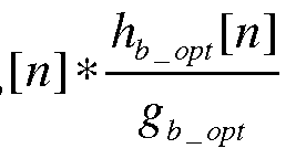 xp [n] = x[n] (10) where the cost function C(h) is minimized to optimize the alternative filter hb[n], and gb opt is the complex gain of that alternative filter. Although probably not a practical solution, it is also technically possible to generate two different filters, one for the input signal and one for the feedback signal, such that both the input and feedback signals are appropriately filtered to align them to each other.
Although the present invention has been described in the context of linearizing an analog sub- system having a non-linear amplifier, the invention can also be implemented in other contexts. For example, the invention can be implemented to linearize an analog sub-system having one or more of the following elements: baseband amplification, IF (intermediate frequency) amplification, RF amplification, frequency upconversion, frequency downconversion, vector modulation. Furthermore, depending on the frequency requirements of the particular application and the frequency capabilities of the physical components used to implement the various elements, upconverter 132 and/or
downconverter 150 of FIG. 1 may be omitted. Note that, in certain implementations, upconversion and/or downconversion may be partially or even completely implemented in the digital domain.
The present invention may be implemented as (analog, digital, or a hybrid of both analog and digital) circuit-based processes, including possible implementation as a single integrated circuit (such as an ASIC or an FPGA), a multi-chip module, a single card, or a multi-card circuit pack. As would be apparent to one skilled in the art, various functions of circuit elements may also be implemented as processing blocks in a software program. Such software may be employed in, for example, a digital signal processor, micro-controller, general-purpose computer, or other processor.
The present invention can be embodied in the form of methods and apparatuses for practicing those methods. The present invention can also be embodied in the form of program code embodied in tangible media, such as magnetic recording media, optical recording media, solid state memory, floppy diskettes, CD-ROMs, hard drives, or any other non-transitory machine-readable storage medium, wherein, when the program code is loaded into and executed by a machine, such as a computer, the machine becomes an apparatus for practicing the invention. The present invention can also be embodied in the form of program code, for example, stored in a non-transitory machine- readable storage medium including being loaded into and/or executed by a machine, wherein, when the program code is loaded into and executed by a machine, such as a computer, the machine becomes an apparatus for practicing the invention. When implemented on a general-purpose processor, the program code segments combine with the processor to provide a unique device that operates analogously to specific logic circuits.
It should be appreciated by those of ordinary skill in the art that any block diagrams herein represent conceptual views of illustrative circuitry embodying the principles of the invention.
Similarly, it will be appreciated that any flow charts, flow diagrams, state transition diagrams, pseudo code, and the like represent various processes which may be substantially represented in computer readable medium and so executed by a computer or processor, whether or not such computer or processor is explicitly shown.
Unless explicitly stated otherwise, each numerical value and range should be interpreted as being approximate as if the word "about" or "approximately" preceded the value of the value or range.
It will be further understood that various changes in the details, materials, and arrangements of the parts which have been described and illustrated in order to explain the nature of this invention may be made by those skilled in the art without departing from the scope of the invention as expressed in the following claims.
The use of figure numbers and/or figure reference labels in the claims is intended to identify one or more possible embodiments of the claimed subject matter in order to facilitate the
interpretation of the claims. Such use is not to be construed as necessarily limiting the scope of those claims to the embodiments shown in the corresponding figures.
It should be understood that the steps of the exemplary methods set forth herein are not necessarily required to be performed in the order described, and the order of the steps of such methods should be understood to be merely exemplary. Likewise, additional steps may be included in such methods, and certain steps may be omitted or combined, in methods consistent with various embodiments of the present invention.
Although the elements in the following method claims, if any, are recited in a particular sequence with corresponding labeling, unless the claim recitations otherwise imply a particular sequence for implementing some or all of those elements, those elements are not necessarily intended to be limited to being implemented in that particular sequence.
Reference herein to "one embodiment" or "an embodiment" means that a particular feature, structure, or characteristic described in connection with the embodiment can be included in at least one embodiment of the invention. The appearances of the phrase "in one embodiment" in various places in the specification are not necessarily all referring to the same embodiment, nor are separate or alternative embodiments necessarily mutually exclusive of other embodiments. The same applies to the term "implementation."
The embodiments covered by the claims in this application are limited to embodiments that (1) are enabled by this specification and (2) correspond to statutory subject matter. Non-enabled embodiments and embodiments that correspond to non-statutory subject matter are explicitly disclaimed even if they fall within the scope of the claims.
Claims
1. A linearized system comprising:
an adaptive pre-distorter configured to pre-distort an input signal to generate a pre-distorted signal;
a non-linear transmit path configured to generate an output signal from the pre-distorted signal; and
a feedback path configured to generate a feedback signal based on the output signal, wherein the system is configured to adapt the adaptive pre-distorter by:
(1) optimizing a filter that minimizes a cost function based on the input signal and the feedback signal;
(2) applying the optimized filter to the input signal or the feedback signal to generate an aligned input signal and an aligned feedback signal; and
(3) updating the adaptive pre-distorter based on the aligned input and feedback signals.
2. The invention of claim 1, wherein the non-linear transmit path comprises a non-linear power amplifier.
3. The invention of claim 1, wherein the cost function C(h) is given by:

where:
x[n] is the input signal;
y fb [_n\ is the feedback signal;
ha[n] is the filter;
* denotes convolution; and
E{ . } is an expectation operator.
4. The invention of claim 3, wherein the system is configured to compute the compli of the optimized filter ha opt[n] at zero frequency according to: 
where:
NH is the length of the optimized filter.
5. The invention of claim 4, wherein: system is configured to generate the aligned input signal xp[n] according xp [n] = x[n] - o a_opt
and the system is configured to generate the aligned feedback signal ¾¾j,[w] according to:

6. The invention of claim 1, wherein the cost function C(h) is given by:
C(h) = E{(yfb [n] * hb[n] - x[n]f }
where:
x[n] is the input signal;
_y^ [«] is the feedback signal;
hb[n] is the filter;
* denotes convolution; and
E{ . } is an expectation operator.
7. The invention of claim 6, wherein the system is configured to compute the complex gain gb of the optimized filter hb opt[n] at zero frequency according to: 
where:
NH is the length of the optimized filter.
8. The invention of claim 7, wherein:
the system is configured to generate the aligned feedback signal  according to:
and the system is configured to generate the aligned input signal xp[n] according to:
xp[n] = x[n] .
9. The invention of claim 1, wherein the system is configured to adaptively update the adaptive pre-distorter in real time.
10. The invention of claim 1, wherein the system is configured to adaptively update the adaptive pre-distorter in non-real time. -lO-
11. A method of linearizing a non-linear transmit path, the method comprising:
applying an input signal to an adaptive pre-distorter to generate a pre-distorted signal;
applying the pre-distorted signal to the non-linear transmit path to generate an output signal; and generating a feedback signal based on the output signal using a feedback path; and
adapting the adaptive pre-distorter by:
(1) optimizing a filter that minimizes a cost function based on the input signal and the feedback signal;
(2) applying the optimized filter to the input signal or the feedback signal to generate an aligned input signal and an aligned feedback signal; and
(3) updating the adaptive pre-distorter based on the aligned input and feedback signals.
12. The invention of claim 11, wherein the non-linear transmit path comprises a non-linear power amplifier.
13. The invention of claim 11, wherein the cost function C(h) is given by:

where:
the input signal;
_y^ [«] is the feedback signal;
ha[n] is the filter; and
E{ . } is an expectation operator.
14. The invention of claim 13, wherein the complex gain ga _opt of the optimized filter ha opt[n] is computed at zero frequency according to:
N„-l
§ a _ opt / _ opt ik] where:
Nh is the length of the optimized filter.
15. The invention of claim 14, wherein:
the aligned input signal xp[n] is generated according to: x \n] = x[n] * K_optM
& a_opt
and the aligned feedback signal ¾¾j,[w] is generated according to: 
16. The invention of claim 11, wherein the cost function C(h) is given

where:
x[n] is the input signal;
y fb [_n\ is the feedback signal;
hb[n] is the filter;
* denotes convolution; and
E{ . } is an expectation operator.
17. The invention of claim 16, wherein the complex gain gb_opt of the optimized filter hb opt[n] is computed at zero frequency according to: 
where:
Nh is the length of the optimized filter.
18. The invention of claim 17, wherein:
the aligned feedback signal ¾¾j,[w] is generated according to: yfi_P in] = yfi [n]
6 b_opt
and the aligned input signal xp[n] is generated according to:
xp[n] = x[n] .
19. The invention of claim 11, wherein the adaptive pre-distorter is adaptively updated in real time.
20. The invention of claim 11, wherein the adaptive pre-distorter is adaptively updated in non-real time.
Priority Applications (1)
| Application Number | Priority Date | Filing Date | Title |
|---|---|---|---|
| CN201280023035.6A CN103620952A (en) | 2011-05-12 | 2012-05-01 | Digital pre-distortion with carrier cancellation |
Applications Claiming Priority (4)
| Application Number | Priority Date | Filing Date | Title |
|---|---|---|---|
| US201161485161P | 2011-05-12 | 2011-05-12 | |
| US61/485,161 | 2011-05-12 | ||
| US13/431,398 US8660207B2 (en) | 2011-05-12 | 2012-03-27 | Digital pre-distortion with carrier cancellation |
| US13/431,398 | 2012-03-27 |
Publications (1)
| Publication Number | Publication Date |
|---|---|
| WO2012154445A1 true WO2012154445A1 (en) | 2012-11-15 |
Family
ID=46149723
Family Applications (1)
| Application Number | Title | Priority Date | Filing Date |
|---|---|---|---|
| PCT/US2012/035947 Ceased WO2012154445A1 (en) | 2011-05-12 | 2012-05-01 | Digital pre-distortion with carrier cancellation |
Country Status (3)
| Country | Link |
|---|---|
| US (1) | US8660207B2 (en) |
| CN (1) | CN103620952A (en) |
| WO (1) | WO2012154445A1 (en) |
Families Citing this family (2)
| Publication number | Priority date | Publication date | Assignee | Title |
|---|---|---|---|---|
| US9768880B2 (en) | 2015-05-20 | 2017-09-19 | Ciena Corporation | Method and system for nonlinear interference mitigation |
| EP3993262A1 (en) * | 2020-11-02 | 2022-05-04 | Nokia Solutions and Networks Oy | A radio apparatus |
Citations (1)
| Publication number | Priority date | Publication date | Assignee | Title |
|---|---|---|---|---|
| US7804359B1 (en) * | 2008-10-23 | 2010-09-28 | Scintera Networks, Inc. | Linearization with memory compensation |
Family Cites Families (13)
| Publication number | Priority date | Publication date | Assignee | Title |
|---|---|---|---|---|
| US6798843B1 (en) | 1999-07-13 | 2004-09-28 | Pmc-Sierra, Inc. | Wideband digital predistortion linearizer for nonlinear amplifiers |
| US6697436B1 (en) | 1999-07-13 | 2004-02-24 | Pmc-Sierra, Inc. | Transmission antenna array system with predistortion |
| US6570444B2 (en) | 2000-01-26 | 2003-05-27 | Pmc-Sierra, Inc. | Low noise wideband digital predistortion amplifier |
| US7197085B1 (en) | 2002-03-08 | 2007-03-27 | Andrew Corporation | Frequency-dependent magnitude pre-distortion for reducing spurious emissions in communication networks |
| US7583754B2 (en) | 2002-10-31 | 2009-09-01 | Zte Corporation | Method and system for broadband predistortion linearization |
| US7251293B2 (en) | 2003-06-27 | 2007-07-31 | Andrew Corporation | Digital pre-distortion for the linearization of power amplifiers with asymmetrical characteristics |
| JP4909261B2 (en) * | 2004-03-25 | 2012-04-04 | ネットロジック・マイクロシステムズ・インコーポレーテッド | Model-based distortion reduction in power amplifiers |
| US7606322B2 (en) | 2004-10-07 | 2009-10-20 | Microelectronics Technology Inc. | Digital pre-distortion technique using nonlinear filters |
| JP2006148854A (en) | 2004-10-21 | 2006-06-08 | Hitachi Kokusai Electric Inc | Multi-carrier receiver and transmitter with delay correction function |
| CA2576778C (en) | 2006-02-07 | 2014-09-02 | Xinping Huang | Self-calibrating multi-port circuit and method |
| US7783260B2 (en) | 2006-04-27 | 2010-08-24 | Crestcom, Inc. | Method and apparatus for adaptively controlling signals |
| US7729445B2 (en) | 2006-09-27 | 2010-06-01 | Intel Corporation | Digital outphasing transmitter architecture |
| US7773692B2 (en) * | 2006-12-01 | 2010-08-10 | Texas Instruments Incorporated | System and methods for digitally correcting a non-linear element using a digital filter for predistortion |
-
2012
- 2012-03-27 US US13/431,398 patent/US8660207B2/en active Active
- 2012-05-01 WO PCT/US2012/035947 patent/WO2012154445A1/en not_active Ceased
- 2012-05-01 CN CN201280023035.6A patent/CN103620952A/en active Pending
Patent Citations (1)
| Publication number | Priority date | Publication date | Assignee | Title |
|---|---|---|---|---|
| US7804359B1 (en) * | 2008-10-23 | 2010-09-28 | Scintera Networks, Inc. | Linearization with memory compensation |
Non-Patent Citations (1)
| Title |
|---|
| W.H. PRESS; B.P. FLANNERY; S.A. TEUKOLSKY; W.T. VETTERLING: "Numerical Recipes: The Art of Scientific Computing", 1986, NEW YORK: CAMBRIDGE UNIVERSITY PRESS |
Also Published As
| Publication number | Publication date |
|---|---|
| CN103620952A (en) | 2014-03-05 |
| US20120288028A1 (en) | 2012-11-15 |
| US8660207B2 (en) | 2014-02-25 |
Similar Documents
| Publication | Publication Date | Title |
|---|---|---|
| US8711976B2 (en) | Pre-distortion architecture for compensating non-linear effects | |
| CN101911477B (en) | Predistorter | |
| US8537041B2 (en) | Interpolation-based digital pre-distortion architecture | |
| JP4255849B2 (en) | Power series digital predistorter | |
| CN106031027B (en) | Method and apparatus for digital predistortion for switched mode power amplifiers | |
| KR100681727B1 (en) | Additive digital predistortion system using parallel path coordinate transformation | |
| JP5120178B2 (en) | Nonlinear system inverse characteristic identification device and method, power amplification device, and power amplifier predistorter | |
| US20140161207A1 (en) | Digital pre-distortion system for radio frequency transmitters with reduced sampling rate in observation loop | |
| JP5664116B2 (en) | Power amplification apparatus, distortion compensation coefficient updating method thereof, and transmission apparatus | |
| CN107251420B (en) | Method, apparatus and non-transitory computer readable medium for vector signal alignment | |
| JP2009111958A (en) | Predistorter | |
| CN109075745B (en) | predistortion device | |
| CN104426485B (en) | Digital predistortion apparatus and method | |
| US20040119534A1 (en) | Model-based feed-forward linearization of amplifiers | |
| JP5247629B2 (en) | Amplifier power supply voltage controller | |
| KR20120070047A (en) | Predistorter for compensating of nonlinear distortion and method for the same | |
| CN104184421A (en) | Power amplifier apparatus, transmitter apparatus, and method of controlling the power amplifier apparatus | |
| US8660207B2 (en) | Digital pre-distortion with carrier cancellation | |
| Liu et al. | On the robustness of look-up table digital predistortion in the presence of loop delay error | |
| JP2011507444A (en) | Linear power amplifier | |
| CN101765187A (en) | Digital pre-distortion method and system | |
| JP2014116691A (en) | High frequency amplification device and distortion compensation method | |
| JP2011176686A (en) | Predistortion compensation circuit and memory effect distortion compensation method for power amplifier | |
| KR20090125597A (en) | Nonlinear Model Parameter Extraction Method of Wideband Signal Using Narrowband Signal, Predistortion Apparatus and Method Using the Same | |
| JP6296709B2 (en) | Distortion compensation device |
Legal Events
| Date | Code | Title | Description |
|---|---|---|---|
| 121 | Ep: the epo has been informed by wipo that ep was designated in this application |
Ref document number: 12723556 Country of ref document: EP Kind code of ref document: A1 |
|
| NENP | Non-entry into the national phase |
Ref country code: DE |
|
| 122 | Ep: pct application non-entry in european phase |
Ref document number: 12723556 Country of ref document: EP Kind code of ref document: A1 |