WO2012149178A2 - Open loop spatial processing - Google Patents
Open loop spatial processing Download PDFInfo
- Publication number
- WO2012149178A2 WO2012149178A2 PCT/US2012/035239 US2012035239W WO2012149178A2 WO 2012149178 A2 WO2012149178 A2 WO 2012149178A2 US 2012035239 W US2012035239 W US 2012035239W WO 2012149178 A2 WO2012149178 A2 WO 2012149178A2
- Authority
- WO
- WIPO (PCT)
- Prior art keywords
- wtru
- precoder
- data
- reference signals
- specific reference
- Prior art date
- Legal status (The legal status is an assumption and is not a legal conclusion. Google has not performed a legal analysis and makes no representation as to the accuracy of the status listed.)
- Ceased
Links
Classifications
-
- H—ELECTRICITY
- H04—ELECTRIC COMMUNICATION TECHNIQUE
- H04B—TRANSMISSION
- H04B7/00—Radio transmission systems, i.e. using radiation field
- H04B7/02—Diversity systems; Multi-antenna system, i.e. transmission or reception using multiple antennas
- H04B7/04—Diversity systems; Multi-antenna system, i.e. transmission or reception using multiple antennas using two or more spaced independent antennas
- H04B7/0413—MIMO systems
- H04B7/0456—Selection of precoding matrices or codebooks, e.g. using matrices antenna weighting
-
- H—ELECTRICITY
- H04—ELECTRIC COMMUNICATION TECHNIQUE
- H04B—TRANSMISSION
- H04B7/00—Radio transmission systems, i.e. using radiation field
- H04B7/02—Diversity systems; Multi-antenna system, i.e. transmission or reception using multiple antennas
- H04B7/022—Site diversity; Macro-diversity
-
- H—ELECTRICITY
- H04—ELECTRIC COMMUNICATION TECHNIQUE
- H04B—TRANSMISSION
- H04B7/00—Radio transmission systems, i.e. using radiation field
- H04B7/02—Diversity systems; Multi-antenna system, i.e. transmission or reception using multiple antennas
- H04B7/04—Diversity systems; Multi-antenna system, i.e. transmission or reception using multiple antennas using two or more spaced independent antennas
- H04B7/06—Diversity systems; Multi-antenna system, i.e. transmission or reception using multiple antennas using two or more spaced independent antennas at the transmitting station
- H04B7/0613—Diversity systems; Multi-antenna system, i.e. transmission or reception using multiple antennas using two or more spaced independent antennas at the transmitting station using simultaneous transmission
- H04B7/0615—Diversity systems; Multi-antenna system, i.e. transmission or reception using multiple antennas using two or more spaced independent antennas at the transmitting station using simultaneous transmission of weighted versions of same signal
- H04B7/0619—Diversity systems; Multi-antenna system, i.e. transmission or reception using multiple antennas using two or more spaced independent antennas at the transmitting station using simultaneous transmission of weighted versions of same signal using feedback from receiving side
- H04B7/0621—Feedback content
- H04B7/0626—Channel coefficients, e.g. channel state information [CSI]
-
- H—ELECTRICITY
- H04—ELECTRIC COMMUNICATION TECHNIQUE
- H04L—TRANSMISSION OF DIGITAL INFORMATION, e.g. TELEGRAPHIC COMMUNICATION
- H04L25/00—Baseband systems
- H04L25/02—Details ; arrangements for supplying electrical power along data transmission lines
- H04L25/0202—Channel estimation
- H04L25/0204—Channel estimation of multiple channels
-
- H—ELECTRICITY
- H04—ELECTRIC COMMUNICATION TECHNIQUE
- H04L—TRANSMISSION OF DIGITAL INFORMATION, e.g. TELEGRAPHIC COMMUNICATION
- H04L25/00—Baseband systems
- H04L25/02—Details ; arrangements for supplying electrical power along data transmission lines
- H04L25/03—Shaping networks in transmitter or receiver, e.g. adaptive shaping networks
- H04L25/03006—Arrangements for removing intersymbol interference
- H04L25/03343—Arrangements at the transmitter end
-
- H—ELECTRICITY
- H04—ELECTRIC COMMUNICATION TECHNIQUE
- H04L—TRANSMISSION OF DIGITAL INFORMATION, e.g. TELEGRAPHIC COMMUNICATION
- H04L25/00—Baseband systems
- H04L25/02—Details ; arrangements for supplying electrical power along data transmission lines
- H04L25/03—Shaping networks in transmitter or receiver, e.g. adaptive shaping networks
- H04L25/03006—Arrangements for removing intersymbol interference
- H04L2025/0335—Arrangements for removing intersymbol interference characterised by the type of transmission
- H04L2025/03426—Arrangements for removing intersymbol interference characterised by the type of transmission transmission using multiple-input and multiple-output channels
Definitions
- This application is related to wireless communications.
- MIMO spatial multiplexing
- 3GPP 3 rd Generation Partnership Project
- LTE long term evolution
- Open-loop spatial multiplexing refers to linearly pre-coded MIMO transmissions where either full or partial channel state information (CSI) is available at the transmitter.
- Open-loop spatial multiplexing corresponds to MIMO transmissions where CSI is not available at the transmitter or is partially available, (e.g., long-term measurements may be available but short-term measurements allowing fast adaptation are not).
- Open-loop spatial multiplexing is a good candidate for high mobility cases.
- a base station may precode wireless transmit/receive unit (WTRU)- specific reference signals and data that are transmitted to a WTRU using a randomly selected precoder.
- the precoder may be selected based on a predefined precoder selection sequence or by the base station.
- a different precoder may be applied to different resource blocks (RBs).
- RBs resource blocks
- CDD large delay cyclic delay diversity
- 1920856-1 Fourier transform (DFT) spreading may be applied on the WTRU-specific reference signals and the data.
- DFT 1920856-1 Fourier transform
- spatial diversity gain is achieved by dynamically scheduling resources between transmission points.
- a hopping scheme may be applied across the transmission points as the resources are dynamically partitioned between the transmission points.
- a different randomly selected precoder may be applied to each RB transmitted from a different transmission point.
- FIG. 1A is a system diagram of an example communications system in which one or more disclosed embodiments may be implemented
- FIG. IB is a system diagram of an example wireless transmit/receive unit (WTRU) that may be used within the communications system illustrated in FIG. 1A;
- WTRU wireless transmit/receive unit
- FIG. 1C is a system diagram of an example radio access network and an example core network that may be used within the communications system illustrated in FIG. 1A;
- FIG. 2 illustrates a transmit chain of open-loop spatial multiplexing in long term evolution release 8
- FIG. 3 shows an example random precoding block diagram
- FIG. 4 shows an example open-loop spatial multiplexing from geographically distributed transmit antennas.
- FIG. 1A is a diagram of an example communications system 100 in which one or more disclosed embodiments may be implemented.
- the communications system 100 may be a multiple access system that provides content, such as voice, data, video, messaging, broadcast, etc., to multiple users.
- the communications system 100 may enable multiple wireless users to access such content through the sharing of system resources, including wireless bandwidth.
- the communications systems 100 may employ one or more channel access methods, such as code division multiple access (CDMA), time division multiple access (TDMA), frequency division multiple access (FDMA), orthogonal FDMA (OFDMA), single-carrier FDMA (SC-FDMA), and the like.
- CDMA code division multiple access
- TDMA time division multiple access
- FDMA frequency division multiple access
- OFDMA orthogonal FDMA
- SC-FDMA single-carrier FDMA
- the communications system 100 may include wireless transmit/receive units (WTRUs) 102a, 102b, 102c, 102d, a radio access network (RAN) 104, a core network 106, a public switched telephone network (PSTN) 108, the Internet 110, and other networks 112, though it will be appreciated that the disclosed embodiments contemplate any number of WTRUs, base stations, networks, and/or network elements.
- WTRUs 102a, 102b, 102c, 102d may be any type of device configured to operate and/or communicate in a wireless environment.
- the WTRUs 102a, 102b, 102c, 102d may be configured to transmit and/or receive wireless signals and may include user equipment (UE), a mobile station, a fixed or mobile subscriber unit, a pager, a cellular telephone, a personal digital assistant (PDA), a smartphone, a laptop, a netbook, a personal computer, a wireless sensor, consumer electronics, and the like.
- UE user equipment
- PDA personal digital assistant
- smartphone a laptop
- netbook a personal computer
- a wireless sensor consumer electronics, and the like.
- the communications systems 100 may also include a base station
- Each of the base stations 114a, 114b may be any type of device configured to wirelessly interface with at least one of the WTRUs 102a, 102b, 102c, 102d to facilitate access to one or more communication networks, such as the core network 106, the Internet 110, and/or the networks 112.
- the base stations 114a, 114b may be a base transceiver station (BTS), a Node-B, an eNode-B, a Home Node- B, a Home eNode-B, a site controller, an access point (AP), a wireless router, and the like. While the base stations 114a, 114b are each depicted as a single element, it will be appreciated that the base stations 114a, 114b may include any number of interconnected base stations and/or network elements.
- the base station 114a may be part of the RAN 104, which may also include other base stations and/or network elements (not shown), such as a base station controller (BSC), a radio network controller (RNC), relay nodes, etc.
- BSC base station controller
- RNC radio network controller
- the base station 114a and/or the base station 114b may be configured to transmit and/or receive wireless signals within a particular geographic region, which may be referred to as a cell (not shown).
- the cell may further be divided into cell sectors.
- the cell associated with the base station 114a may be divided into three sectors.
- the base station 114a may include three transceivers, i.e., one for each sector of the cell.
- the base station 114a may employ multiple -input multiple output (MIMO) technology and, therefore, may utilize multiple transceivers for each sector of the cell.
- MIMO multiple -input multiple output
- the base stations 114a, 114b may communicate with one or more of the WTRUs 102a, 102b, 102c, 102d over an air interface 116, which may be any suitable wireless communication link, (e.g., radio frequency (RF), microwave, infrared (IR), ultraviolet (UV), visible light, etc.).
- the air interface 116 may be established using any suitable radio access technology (RAT).
- RAT radio access technology
- the base station 114a in the RAN 104 and the WTRUs 102a, 102b, 102c may implement a radio technology such as Universal Mobile Telecommunications System (UMTS) Terrestrial Radio Access (UTRA), which may establish the air interface 116 using wideband CDMA (WCDMA).
- WCDMA may include communication protocols such as High-Speed Packet Access (HSPA) and/or Evolved HSPA (HSPA+).
- HSPA may include High-Speed Downlink Packet Access (HSDPA) and/or High-Speed Uplink Packet Access (HSUPA).
- the base station 114a and the WTRUs are identical to the base station 114a and the WTRUs.
- 102a, 102b, 102c may implement a radio technology such as Evolved UMTS
- E-UTRA 1920856-1 Terrestrial Radio Access
- LTE Long Term Evolution
- LTE-A LTE-Advanced
- the base station 114a and the WTRUs are identical to the base station 114a and the WTRUs.
- 102a, 102b, 102c may implement radio technologies such as IEEE 802.16 (i.e., Worldwide Interoperability for Microwave Access (WiMAX)), CDMA2000, CDMA2000 IX, CDMA2000 EV-DO, Interim Standard 2000 (IS-2000), Interim Standard 95 (IS-95), Interim Standard 856 (IS-856), Global System for Mobile communications (GSM), Enhanced Data rates for GSM Evolution (EDGE), GSM EDGE (GERAN), and the like.
- IEEE 802.16 i.e., Worldwide Interoperability for Microwave Access (WiMAX)
- CDMA2000, CDMA2000 IX, CDMA2000 EV-DO Code Division Multiple Access 2000
- IS-95 Interim Standard 95
- IS-856 Interim Standard 856
- GSM Global System for Mobile communications
- GSM Global System for Mobile communications
- EDGE Enhanced Data rates for GSM Evolution
- GERAN GSM EDGERAN
- the base station 114b in FIG. 1A may be a wireless router, Home
- Node B, Home eNode B, or access point may utilize any suitable RAT for facilitating wireless connectivity in a localized area, such as a place of business, a home, a vehicle, a campus, and the like.
- the base station 114b and the WTRUs 102c, 102d may implement a radio technology such as IEEE 802.11 to establish a wireless local area network (WLAN).
- the base station 114b and the WTRUs 102c, 102d may implement a radio technology such as IEEE 802.15 to establish a wireless personal area network (WPAN).
- WLAN wireless local area network
- WPAN wireless personal area network
- the base station 114b and the WTRUs 102c, 102d may utilize a cellular-based RAT, (e.g., WCDMA, CDMA2000, GSM, LTE, LTE-A, etc.), to establish a picocell or femtocell.
- a cellular-based RAT e.g., WCDMA, CDMA2000, GSM, LTE, LTE-A, etc.
- the base station 114b may have a direct connection to the Internet 110.
- the base station 114b may not be required to access the Internet 110 via the core network 106.
- the RAN 104 may be in communication with the core network
- the core network 106 may be any type of network configured to provide voice, data, applications, and/or voice over internet protocol (VoIP) services to one or more of the WTRUs 102a, 102b, 102c, 102d.
- the core network 106 may provide call control, billing services, mobile location-based services, pre-paid calling, Internet connectivity, video distribution, etc., and/or perform high- level security functions, such as user authentication.
- VoIP voice over internet protocol
- 1920856-1 may be in direct or indirect communication with other RANs that employ the same RAT as the RAN 104 or a different RAT.
- the core network 106 may also be in communication with another RAN (not shown) employing a GSM radio technology.
- the core network 106 may also serve as a gateway for the
- the PSTN 108 may include circuit-switched telephone networks that provide plain old telephone service (POTS).
- POTS plain old telephone service
- the Internet 110 may include a global system of interconnected computer networks and devices that use common communication protocols, such as the transmission control protocol (TCP), user datagram protocol (UDP) and the internet protocol (IP) in the TCP/IP internet protocol suite.
- TCP transmission control protocol
- UDP user datagram protocol
- IP internet protocol
- the networks 112 may include wired or wireless communications networks owned and/or operated by other service providers.
- the networks 112 may include another core network connected to one or more RANs, which may employ the same RAT as the RAN 104 or a different RAT.
- Some or all of the WTRUs 102a, 102b, 102c, 102d in the communications system 100 may include multi-mode capabilities, i.e., the WTRUs 102a, 102b, 102c, 102d may include multiple transceivers for communicating with different wireless networks over different wireless links.
- the WTRU 102c shown in FIG. 1A may be configured to communicate with the base station 114a, which may employ a cellular -based radio technology, and with the base station 114b, which may employ an IEEE 802 radio technology.
- FIG. IB is a system diagram of an example WTRU 102.
- the WTRU 102 may include a processor 118, a transceiver 120, a transmit/receive element 122, a speaker/microphone 124, a keypad 126, a display/touchpad 128, non-removable memory 130, removable memory 132, a power source 134, a global positioning system (GPS) chipset 136, and other peripherals 138.
- GPS global positioning system
- the processor 118 may be a general purpose processor, a special purpose processor, a conventional processor, a digital signal processor (DSP), a plurality of microprocessors, one or more microprocessors in association with a DSP core, a controller, a microcontroller, Application Specific Integrated Circuits (ASICs), Field Programmable Gate Array (FPGAs) circuits, any other type of integrated circuit (IC), a state machine, and the like.
- the processor 118 may perform signal coding, data processing, power control, input/output processing, and/or any other functionality that enables the WTRU 102 to operate in a wireless environment.
- the processor 118 may be coupled to the transceiver 120, which may be coupled to the transmit/receive element 122. While FIG. IB depicts the processor 118 and the transceiver 120 as separate components, it will be appreciated that the processor 118 and the transceiver 120 may be integrated together in an electronic package or chip.
- the transmit/receive element 122 may be configured to transmit signals to, or receive signals from, a base station (e.g., the base station 114a) over the air interface 116.
- a base station e.g., the base station 114a
- the transmit/receive element 122 may be an antenna configured to transmit and/or receive RF signals.
- the transmit/receive element 122 may be an emitter/detector configured to transmit and/or receive IR, UV, or visible light signals, for example.
- the transmit/receive element 122 may be configured to transmit and receive both RF and light signals. It will be appreciated that the transmit/receive element 122 may be configured to transmit and/or receive any combination of wireless signals.
- the WTRU 102 may include any number of transmit/receive elements 122. More specifically, the WTRU 102 may employ MIMO technology. Thus, in one embodiment, the WTRU 102 may include two or more transmit/receive elements 122 (e.g., multiple
- 1920856-1 antennas for transmitting and receiving wireless signals over the air interface 116.
- the transceiver 120 may be configured to modulate the signals that are to be transmitted by the transmit/receive element 122 and to demodulate the signals that are received by the transmit/receive element 122.
- the WTRU 102 may have multi-mode capabilities.
- the transceiver 120 may include multiple transceivers for enabling the WTRU 102 to communicate via multiple RATs, such as UTRA and IEEE 802.11, for example.
- the processor 118 of the WTRU 102 may be coupled to, and may receive user input data from, the speaker/microphone 124, the keypad 126, and/or the display/touchpad 128 (e.g., a liquid crystal display (LCD) display unit or organic light- emitting diode (OLED) display unit).
- the processor 118 may also output user data to the speaker/microphone 124, the keypad 126, and/or the display/touchpad 128.
- the processor 118 may access information from, and store data in, any type of suitable memory, such as the non-removable memory 130 and/or the removable memory 132.
- the nonremovable memory 130 may include random-access memory (RAM), read-only memory (ROM), a hard disk, or any other type of memory storage device.
- the removable memory 132 may include a subscriber identity module (SIM) card, a memory stick, a secure digital (SD) memory card, and the like.
- SIM subscriber identity module
- SD secure digital
- the processor 118 may access information from, and store data in, memory that is not physically located on the WTRU 102, such as on a server or a home computer (not shown).
- the processor 118 may receive power from the power source 134, and may be configured to distribute and/or control the power to the other components in the WTRU 102.
- the power source 134 may be any suitable device for powering the WTRU 102.
- the power source 134 may include one or more dry cell batteries (e.g., nickel- cadmium (NiCd), nickel-zinc (NiZn), nickel metal hydride (NiMH), lithium-ion (Li-ion), etc.), solar cells, fuel cells, and the like.
- the processor 118 may also be coupled to the GPS chipset 136, which may be configured to provide location information, (e.g., longitude and latitude), regarding the current location of the WTRU 102.
- location information e.g., longitude and latitude
- the WTRU 102 may receive location information over the air interface 116 from a base station, (e.g., base stations 114a, 114b), and/or determine its location based on the timing of the signals being received from two or more nearby base stations. It will be appreciated that the WTRU 102 may acquire location information by way of any suitable location- determination method while remaining consistent with an embodiment.
- the processor 118 may further be coupled to other peripherals
- the peripherals 138 may include one or more software and/or hardware modules that provide additional features, functionality and/or wired or wireless connectivity.
- the peripherals 138 may include an accelerometer, an e-compass, a satellite transceiver, a digital camera (for photographs or video), a universal serial bus (USB) port, a vibration device, a television transceiver, a hands free headset, a Bluetooth® module, a frequency modulated (FM) radio unit, a digital music player, a media player, a video game player module, an Internet browser, and the like.
- an accelerometer an e-compass, a satellite transceiver, a digital camera (for photographs or video), a universal serial bus (USB) port, a vibration device, a television transceiver, a hands free headset, a Bluetooth® module, a frequency modulated (FM) radio unit, a digital music player, a media player, a video game player module, an Internet browser, and the like.
- FM frequency modulated
- FIG. 1C is a system diagram of the RAN 104 and the core network 106 according to an embodiment.
- the RAN 104 may employ an E-UTRA radio technology to communicate with the WTRUs 102a, 102b, 102c over the air interface 116.
- the RAN 104 may also be in communication with the core network 106.
- the RAN 104 may include eNode-Bs 140a, 140b, 140c, though it will be appreciated that the RAN 104 may include any number of eNode-Bs while remaining consistent with an embodiment.
- the eNode-Bs 140a, 140b, 140c may each include one or more transceivers for communicating with the WTRUs 102a, 102b, 102c over the air interface 116.
- the eNode-Bs 140a, 140b, 140c may implement MIMO technology.
- 1920856-1 eNode-B 140a may use multiple antennas to transmit wireless signals to, and receive wireless signals from, the WTRU 102a.
- Each of the eNode-Bs 140a, 140b, 140c may be associated with a particular cell (not shown) and may be configured to handle radio resource management decisions, handover decisions, scheduling of users in the uplink and/or downlink, and the like. As shown in FIG. 1C, the eNode-Bs 140a, 140b, 140c may communicate with one another over an X2 interface.
- the core network 106 shown in FIG. 1C may include a mobility management gateway entity (MME) 142, a serving gateway 144, and a packet data network (PDN) gateway 146. While each of the foregoing elements are depicted as part of the core network 106, it will be appreciated that any one of these elements may be owned and/or operated by an entity other than the core network operator.
- MME mobility management gateway entity
- PDN packet data network
- the MME 142 may be connected to each of the eNode-Bs 140a,
- the MME 142 may be responsible for authenticating users of the WTRUs 102a, 102b, 102c, bearer activation/deactivation, selecting a particular serving gateway during an initial attach of the WTRUs 102a, 102b, 102c, and the like.
- the MME 142 may also provide a control plane function for switching between the RAN 104 and other RANs (not shown) that employ other radio technologies, such as GSM or WCDMA.
- the serving gateway 144 may be connected to each of the eNode
- the serving gateway 144 may generally route and forward user data packets to/from the WTRUs 102a, 102b, 102c.
- the serving gateway 144 may also perform other functions, such as anchoring user planes during inter-eNode-B handovers, triggering paging when downlink data is available for the WTRUs 102a, 102b, 102c, managing and storing contexts of the WTRUs 102a, 102b, 102c, and the like.
- the serving gateway 144 may also be connected to the PDN gateway 146, which may provide the WTRUs 102a, 102b, 102c with access to packet- switched networks, such as the Internet 110, to facilitate
- the core network 106 may facilitate communications with other networks.
- the core network 106 may provide the WTRUs 102a, 102b, 102c with access to circuit- switched networks, such as the PSTN 108, to facilitate communications between the WTRUs 102a, 102b, 102c and traditional land-line communications devices.
- the core network 106 may include, or may communicate with, an IP gateway (e.g., an IP multimedia subsystem (IMS) server) that serves as an interface between the core network 106 and the PSTN 108.
- IMS IP multimedia subsystem
- the core network 106 may provide the WTRUs 102a, 102b, 102c with access to the networks 112, which may include other wired or wireless networks that are owned and/or operated by other service providers.
- Figure 2 illustrates a transmit chain 200 of open-loop spatial multiplexing in LTE Release 8 (LTE R8). Codewords are precoded through the use of a combination of three matrices, where the matrix U 205 in the chain 200 is a fixed DFT precoder, the matrix D(i) 210 is a diagonal matrix representing the large delay cyclic delay diversity (CDD) functionality, and the matrix W 21b is the precoder defined for close-loop spatial multiplexing.
- LTE R8 LTE Release 8
- LTE-A LTE-Advanced
- LTE Release 10 (referring also to LTE Release 10 and beyond), is extended over the LTE R8 scheme to support configurations with up to 8 transmit antennas in the downlink using a WTRU-specific reference signal to improve data coverage.
- SM single-loop SM
- CL-SM channel state information
- the OL-SM may be used to reduce the uplink feedback signaling
- LTE Release 11 LTE Release 11
- CoMP multi-cell coordinated multi-point transmission
- the WTRU may feedback CSI for multiple transmission points (TPs). This implies that the amount of feedback overhead in CoMP may significantly increase, particularly for a large number of WTRUs.
- OL-SM In general, the benefit of OL-SM is reduced by antenna correlation. This problem may be addressed to some extent by using cross polarized antennas. However, as the technology evolves from more conventional deployment types to new heterogeneous deployments, such as those using a shared cell ID distributed antennas approach, an additional de- correlation between the spatial streams at different transmission points may be obtained. Techniques, such as OL-SM may be particularly beneficial in some specific deployment scenarios, such as those using a shared cell identity (ID) distributed antenna scheme, regardless of the WTRU velocity.
- ID shared cell identity
- DM-RS downlink multi-user
- MU multi-user
- CRS cell-specific reference signals
- DM-RS and data are jointly precoded using a single precoder.
- DM-RS and data i.e., identified with a physical downlink shared channel (PDSCH)
- PDSCH physical downlink shared channel
- the precoder may belong to a codebook which contains a set of precoders known to both the base station and the WTRU.
- the random precoder selection may refer to a predefined precoder
- dedicated pilots may be transmitted by the base station and used by the WTRU for data demodulation.
- dedicated pilots may refer to CRS' or DM-RS'.
- DM-RS' are transmitted by the base station and used by the WTRU for data demodulation.
- a PDSCH allocation 300 may comprise multiple resource blocks (RBs) . . . , n, n+1, n+2, n+3, . . . , and a randomly selected precoder 305 may be different for different RBs . . . , n, n+1, n+2, n+3, . . .
- the DM-RSs 310 and associated data channel(s) (i.e., the PDSCHs) 300 sweep different directions across multiple RBs which may cause the channel to appear ergodic or different at the WTRU(s).
- Cn refers to a specific occurrence of a precoder codevector that is derived from W(i) as shown herein below.
- the WTRU may be configured through either physical layer signaling, (via, for example, a physical data control channel (PDCCH)), or higher layer signaling.
- the signaling may include precoding granularity information, i.e., information indicating the number of RBs applicable to a randomly selected precoder.
- the WTRU may perform channel estimation on a single RB.
- a randomly selected precoder may be applied across multiple RBs.
- the WTRU may perform channel estimation using multiple RBs using, for example, interpolation and/or extrapolation.
- the precoded Pxl vector for OL-SM (where P is the number of transmit antennas), may be defined as follows:
- the WTRU may assume that the base station cyclically assigns different precoders to different vectors [x (0) (z) ... x ⁇ ⁇ f on the PDSCH as described herein below.
- a different precoder may be used in every FNTM vector, where NTM denotes a resource block size in the frequency domain, (expressed as a number of subcarriers), and P' is the precoding resource block group (RBG), (expressed as a number of RBs in the frequency domain).
- RBG precoding resource block group
- F 1 .
- N c denotes the maximum number of precoders within the codebook containing the set of precoders for a given number of layers. Other methods to select the precoder from the codebook may also be implemented.
- a combination of random precoding, cyclic delay diversity (CDD) and discrete Fourier Transform (DFT) spreading may be used.
- CDD cyclic delay diversity
- DFT discrete Fourier Transform
- the DM-RS' and data that are to be transmitted to a WTRU may be first precoded using a randomly selected precoder.
- the precoding granularity may be either per RB or per RBG and each precoder may belong to a codebook which contains a set of precoders known to both the base station and the WTRU.
- a large delay CDD followed by DFT spreading may be applied at the sub-carrier level on the PDSCH.
- the composite effect of large delay CDD and DFT spreading may provide signal-to-interference and
- Each codeword may be transmitted across antennas.
- FIG. 3 shows the example random precoding.
- both DM-RS and data are subject to the same precoding operation. Therefore, by performing channel estimation using DM-RS, the WTRU may estimate the effective channel for reception of the PDSCH data.
- precoding for SM is defined by:
- the matrix U is a fixed DFT precoder
- the matrix D(i) is a diagonal matrix representing the large delay CDD functionality.
- the diagonal size- ⁇ ⁇ ⁇ matrix D(i) supporting cyclic delay diversity and the size- ⁇ ⁇ ⁇ matrix U may be given by Table 1 for v e ⁇ 2,3,4 ⁇ layers.
- the matrix U and diagonal matrix D(i) may be given by Tables 2 and 3, respectively.
- the matrix W is the precoder defined for CL-SM. For /?
- the WTRU may assume that the base station cyclically assigns different precoders to different vectors [x (0) ( ... on the PDSCH wherein a different precoder is used every FNTM vectors.
- the large delay CDD would be equivalent to layer shifting.
- layers 1,2,3,4 in this order
- layers 4,1,2,3 in this order
- the DM-RS exists on the 1 st , 2 nd , 6 th , 7 th , 11 th and 12 th subcarriers
- the channel estimation may be obtained as shown in Table 4.
- the DM-RS density becomes non-uniform across spatial channels, which may cause performance degradation.
- the channel estimation may be performed as shown in Table 5.
- This DM-RS design may allow averaging or filtering between multiple symbols to further improve DM-RS channel estimation.
- the DM-RS may be precoded differently than data. For example, the large delay CDD matrix D(i) may be dropped in the DM-RS precoding. Alternatively, the DM-RS may be pre- shifted before precoding is performed if D ⁇ i) is desired.
- the data and DM-RS may be precoded separately.
- the DM-RS' and data to be transmitted to a WTRU may each be precoded using a different randomly selected precoder.
- the precoding granularity of PDSCH may be different from that of the DM- RS.
- the precoding granularity for the DM-RS may be either per RB or per RBG, while the precoding granularity for the PDSCH may be at the subcarrier-level, RB-level or RBG-level.
- Each precoder may belong to a different codebook, each containing a set of precoders. In this method, given
- the WTRU may assume that the transmit precoding information for both the DM- RS and PDSCH are known to both the base station and the WTRU.
- the precoding on the DM-RS may be completely bypassed, (i.e., no precoding is performed on DM-RS).
- the precoding on the DM-RS may be fixed or semi-static, (e.g., the WTRU may receive the DM-RS precoding information via radio resource control (RRC) signaling or the DM-RS precoding may be fixed in the specifications).
- RRC radio resource control
- the WTRU may not assume that the estimated channel using the DM-RS is the effective channel for the PDSCH detection.
- the WTRU may perform a channel estimation using the DM-RS for up to eight physical transmit antennas regardless of the number of layers, (assuming that the transmit precoding information is available). Accordingly, the WTRU may need to be informed regarding the number of physical transmit antennas in addition to the number of layers. The WTRU may obtain this information using one of the example methods described herein below.
- the WTRU may be semi- statically configured via higher layer signaling or informed through downlink allocation, (i.e., via a PDCCH), regarding the number of layers and the number of physical antennas at the base station.
- the WTRU may assume that the number of DM-RS antenna ports is the same as the number of channel state information reference signal (CSI-RS) antenna ports.
- CSI-RS channel state information reference signal
- the WTRU may assume one CSI-RS configuration may be associated with the number of DM- RS antenna ports.
- the WTRU may assume that the CSI-RS configuration with a non-zero transmission power is the reference configuration for implicit derivation of the number of DM-RS antenna ports.
- the WTRU may assume that the number of DM-RS antenna ports is the same as the number of channel state information reference signal (CSI-RS) antenna ports.
- 1920856-1 may assume that one of the CSI-RS configurations with a zero transmission power may be the reference configuration for implicit derivation of the number of DM-RS antenna ports.
- the WTRU may derive the number of DM-RS antenna ports blindly. Given that there is a 3 dB power boosting on the DM- RS when both code-division multiplexed groups are used for the DM-RS, the WTRU may blindly detect the number of DM-RS antenna ports through power detection.
- the large delay CDD together with DFT spreading may be applied at the subcarrier-level on the PDSCH.
- the WTRU may assume that information regarding the large delay CDD matrix, the DFT spreading matrix and the precoder are available for PDSCH detection.
- the WTRU may use the channel estimates obtained from the
- the WTRU may then detect the PDSCH based on the knowledge of the CDD, DFT, and precoder matrices used for data.
- the transmission point for geographically distributed antennas refers to a remote radio head (RRH), a relay, or a macro cell.
- RRH remote radio head
- relay a relay
- macro cell a macro cell
- the WTRU may receive each RB within its downlink allocation from different transmission points. This technique is particularly beneficial in cases where the signals transmitted from one or multiple transmission points are experiencing sever shadowing.
- the spatial diversity gain is achieved through the use of a channel encoder, which is applied on multiple RBs within a transport block.
- Dynamic resource scheduling may be used to achieve spatial diversity gain.
- the scheduler performs dynamic resource partitioning between different transmission points in all domains including
- the base station may assign each transmission point a separate CSI-RS resource.
- the WTRU may then be configured via higher layer signaling with one or multiple CSTRS configurations to perform channel measurement and provide channel quality feedback for each transmission point.
- the channel quality reports may be per-subband, where a subband is a collection of sub-carriers that have been allocated for scheduling of data.
- the CSI-RS configuration may be WTRU- specific.
- the WTRU may expect the configuration of CSI-RS and/or zero-power CSI-RS and physical multicast channel (PMCH) in the same subframe of a serving cell.
- PMCH physical multicast channel
- Transmission point hopping may be used to achieve spatial diversity gain.
- the scheduler may apply a hopping scheme across transmission points while performing dynamic resource partitioning in temporal and/or frequency domains.
- the WTRU may receive each RB from a different or randomly selected transmission point.
- the transmission point may belong to a set of transmission points that are allocated by the scheduler to serve the WTRU. Given that each resource allocation comprises multiple RBs, by sweeping across different transmission points, the spatial diversity gain is maximized through the channel decoding process. The chance of experiencing severe shadowing by the WTRU is substantially reduced by randomly choosing a transmission point.
- Transmission points that exhibit similar but uncorrelated channel conditions may be paired or defined in a set by the base station, for either dynamic resource scheduling or transmission point hopping.
- transmission points in an indoor environment may be defined as belonging to the same set.
- a transmission point set may be defined for transmission points which have a similar number of antennas, or similar rank capability.
- a transmission point set may be associated with a particular WTRU category, or categories, that it supports.
- a transmission point set may be associated with a particular CSI-RS measurement set.
- the OL-SM used at each transmission point may be as described herein above or a conventional OL-SM as specified in, for example, LTE R8.
- FIG. 4 shows an example OL-SM system 400 for geographically distributed transmit antennas.
- OL-SM system 400 may include a base station 405 defining a macro cell 405, a RRH 410, a RRH 415. a RRH 420, a WTRU 425 and a WTRU 430.
- the base station may define a set of cyclically defined precoders.
- the set of cyclically defined precoders may be cyclically rotated through a number of transmission points which use the same cell ID in a cell or may be defined for a transmission point set.
- the methods described herein may be applied to transmission points at the edge of the cell, to transmission points which exhibit a greater degree of interference from adjacent transmission points and/or to cells which use a different cell ID.
- SM (where P l is the number of transmit antennas at the / th transmission point ), may b
- the WTRU may assume that the base station cyclically assigns different precoders and different transmission points to different vectors [x (0) ( ... x (t, 1) ( f on the PDSCH.
- the precoders used at each transmission point may belong to the same codebook or a different codebook, depending on the number of physical antennas and/or number of layers supported at each transmission point.
- the WTRU may not assume that the precoder applied at each RB within the multiple allocated RBs belongs to the same codebook.
- the set of transmission points which serves the WTRU 425 includes the base station 405 and two RRHs 410 and 415 and that the WTRU 425 is equipped with two antennas while the base station 405 and the two RRHs 410 and 415 are equipped with eight and four antennas, respectively.
- rank the size of the precoder matrices used at the base station 405 is 8 by 2 while the size of those used at the RRHs 410 and 415 is 4 by 2.
- DFT spreading used for at least heterogeneous deployments.
- a combination of large delay CDD and/or DFT spreading may be applied to benefit from the increased frequency selectivity.
- precoding for spatial multiplexing using geographically distributed antennas may be defined as follows:
- the diagonal size- ⁇ ⁇ ⁇ matrix D(i) supporting cyclic delay diversity and the size- ⁇ ⁇ ⁇ matrix U are both given in Table 1 for v e ⁇ 2,3,4 ⁇ layers and for v e ⁇ 5,6,7,8 ⁇ , the matrix U and diagonal matrix D(i) may be given by Table 2
- Described herein are methods to achieve spatial multiplexing using multiple transmission points. Different layers for OL-SM may be transmitted from different transmission points. This is particularly beneficial in cases where the signals transmitted from one transmission point are spatially correlated. The high spatial correlation results in significant reduction of MIMO channel capacity and may occur when antenna spacing is insufficient or there is a lack of rich scattering environment.
- the OL-SM may be used for high rank transmissions.
- the number of layers for spatial multiplexing may potentially exceed the four layers specified for OL-SM in LTE Rel-8.
- the application of a fixed DFT-based precoding may ensure that the channel coefficients of the antenna ports are uncorrelated.
- the fixed DFT precoder may be removed from the transmission chain.
- precoding for spatial multiplexing using geographically distributed antennas may be defined as follows:
- the diagonal size- ⁇ ⁇ ⁇ matrix D ⁇ i) supporting cyclic delay diversity is given by Table 1 for v e ⁇ 2,3,4 ⁇ and Tables 2 and 3 forv e ⁇ 5,6,7,8 ⁇ , respectively.
- CQLVrank indicator (RI) reporting methods Given that LTE R10 WTRUs and beyond may support DM-RS as part of transmission modes 8 and 9, the WTRU may be configured with transmission mode 8 or 9 or one of their descendents for OL-SM.
- CQI channel quality indicator
- rank indicator rank indicator
- RI reporting methods may be defined to support OL-SM.
- reporting modes 2-0 and 3-0 from LTE R8 or RIO may be extended to transmission modes 8 and 9 or one of their descendents to support OL-SM, where reporting mode 2-0 refers to WTRU-selected subband feedback and reporting mode 3-0 refers to higher layer-configured subband feedback.
- the WTRU may be configured with multiple CSI-RS ports for channel measurements in order to support a rank higher than one.
- the WTRU may report an RI as a part of reporting modes 2-0 and 3- 0.
- the restriction on the number of CSI-RS ports to be used by the WTRU for channel measurements under reporting modes 2-0 and 3-0 may be removed. In other words, for transmission modes 8 and 9, certain reporting modes may be supported on the PUSCH.
- modes 1-2, 2-2, and 3- 1 if the WTRU is configured with PMI/RI reporting and modes 2-0 and 3-0 if the WTRU is configured without PMI reporting.
- modes 1-2, 2-2, and 3-1 if the WTRU is configured with PMI/RI reporting and number of CSI-RS ports > 1 and modes 2-0 and 3-0 if the WTRU is configured without PMI reporting and number of CSI-RS ports > 1.
- the WTRU may calculate the reported CQI values conditioned on the reported RI.
- reporting modes 1-0 and 2-0 from LTE R8/10 may be extended to transmission modes 8 and 9 or one of their descendents to support OL-SM.
- reporting mode 1-0 represents wideband feedback
- reporting mode 2-0 refers to WTRU-selected subband feedback.
- the WTRU may support the following periodic CSI reporting. For transmission mode 8, modes 1-1 and 2-1 if the WTRU is configured with PMI/RI reporting and modes 1-0 and 2-0 if the WTRU is configured without PMI reporting. For transmission mode 9, modes 1-1 and 2-1 if the WTRU is configured with PMI/RI reporting and the number of CSI-RS ports>l and modes 1-0 and 2-0 if the WTRU is configured without PMI reporting or the number of CSI-RS ports > 1.
- the WTRU may calculate the CQI values conditioned on the last reported periodic RI.
- the rank report may be associated to a particular transmission point as a result of scheduling by the base station, or it may be associated with the combined rank of one or more transmission points.
- the CQI reference sub-band for reporting CQI may assume the minimum of the rank of the associated transmission points. For more than two transmission points, this may by inference, imply the CQI report is for at least a 2 or greater rank.
- the WTRU may transmit the CQI/RI reports using time division multiplexing (TDM) for transmission points defined in the above examples in a cyclic manner.
- TDM time division multiplexing
- RI single rank report
- MIMO multiple- input multiple -output
- WTRU wireless transmit/receive unit
- 1920856-1 data via a plurality of antennas.
- the at least one precoder is one of a predefined precoder selection sequence or a base station determined precoder.
- WTRU- specific reference signals are pre- shifted before performing the CDD.
- WTRU-specific references signals are precoded differently than the data.
- WTRU wireless transmit/receive unit
- 1920856-1 [0105] 14. The method as in any one of the embodiments, further comprising dynamically scheduling resources between transmission points in at least one domain.
- each transmission point is assigned a separate channel state information (CSI) reference signal (RS) resource.
- CSI channel state information
- RS reference signal
- a method for multiple -input multiple -output (MIMO) transmissions comprising receiving a transmission including wireless transmit/receive unit (WTRU)- specific reference signals and data via a plurality of antennas, wherein the WTRU- specific reference signals and the data are precoded using a randomly selected precoder.
- WTRU wireless transmit/receive unit
- 1920856-1 precoder belongs to a codebook which contains a set of precoders.
- WTRU- specific reference signals are pre- shifted before performing the CDD.
- a method for multiple -input multiple -output (MIMO) transmissions comprising transmitting data from a plurality of transmission points to a wireless transmit/receive unit (WTRU).
- WTRU wireless transmit/receive unit
- each transmission point is assigned a separate channel state information (CSI) reference signal (RS) resource.
- CSI channel state information
- RS reference signal
- CSI RS configuration is WTRU- specific.
- a method for multiple -input multiple -output (MIMO) transmissions comprising receiving wireless transmit/receive unit (WTRU) -specific reference signals and data that are precoded using a randomly selected precoder.
- WTRU wireless transmit/receive unit
- a method for multiple -input multiple -output (MIMO) transmissions comprising a wireless transmit/receive unit
- WTRU receiving data from a plurality of transmission points.
- the WTRU receives data from the transmission points in a hopping sequence.
- the precoder is selected based on a pre-defined sequence or cycle.
- CDD large delay cyclic delay diversity
- DFT discrete Fourier transform
- CQI channel quality indicator
- RI rank indicator
- the WTRU is configured with multiple channel state information (CSI) reference signal (RS) ports for channel measurements.
- CSI channel state information
- RS reference signal
- the WTRU transmits the CQI or RI using time division multiplexing (TDM).
- TDM time division multiplexing
- a base station comprising a processor, transmitter in communication with the processor and a receiver in communication with the processor, each configured to implement a method as in any one of embodiments 1-74.
- a WTRU comprising a processor, transmitter in communication with the processor and a receiver in communication with the processor, each configured to implement a method as in any one of embodiments 1-74.
- a wireless entity comprising a processor, transmitter in communication with the processor and a receiver in communication with the processor, each configured to implement a method as in any one of embodiments 1-74.
- Examples of computer-readable media include electronic signals (transmitted over wired or wireless connections) and computer-readable storage media.
- Examples of computer-readable storage media include, but are not limited to, a read only memory (ROM), a random access memory (RAM), a register, cache memory, semiconductor memory devices, magnetic media such as internal hard disks and removable disks, magneto -optical media, and optical media such as CD- ROM disks, and digital versatile disks (DVDs).
- a processor in association with software may be used to implement a radio frequency transceiver for use in a WTRU, UE, terminal, base station, RNC, or any host computer.
Landscapes
- Engineering & Computer Science (AREA)
- Computer Networks & Wireless Communication (AREA)
- Signal Processing (AREA)
- Power Engineering (AREA)
- Mobile Radio Communication Systems (AREA)
- Radio Transmission System (AREA)
Abstract
Methods and apparatus for multiple-input multiple-output (MIMO) transmissions are disclosed. A base station may precode wireless transmit/receive unit (WTRU)-specific reference signals and data that are transmitted to a WTRU using a randomly selected precoder. The precoder may be selected based on a predefined precoder selection sequence or by the base station. A different precoder may be applied to different resource blocks (RBs). In addition, a large delay cyclic delay diversity (CDD) or discrete Fourier transform (DFT) spreading may be applied on the WTRU-specific reference signals and the data. For heterogeneous deployed antennas, spatial diversity gain is achieved by dynamically scheduling resources between transmission points. A hopping scheme may be applied across the transmission points as the resources are dynamically partitioned between the transmission points. A different randomly selected precoder may be applied to each RB transmitted from a different transmission point.
Description
OPEN LOOP SPATIAL PROCESSING
CROSS REFERENCE TO RELATED APPLICATIONS
[0001] This application claims the benefit of U.S. provisional application
No. 61/480,459, filed April 29, 2011, the contents of which are hereby incorporated by reference herein.
FIELD OF THE INVENTION
[0002] This application is related to wireless communications.
BACKGROUND
[0003] Both open-loop and closed-loop multiple-input multiple -output
(MIMO) schemes in the form of spatial multiplexing (SM) have been introduced in 3rd Generation Partnership Project (3GPP) long term evolution (LTE) Release 8 (R8) for downlink transmissions. Closed-loop spatial multiplexing refers to linearly pre-coded MIMO transmissions where either full or partial channel state information (CSI) is available at the transmitter. Open-loop spatial multiplexing corresponds to MIMO transmissions where CSI is not available at the transmitter or is partially available, (e.g., long-term measurements may be available but short-term measurements allowing fast adaptation are not). Open-loop spatial multiplexing is a good candidate for high mobility cases.
SUMMARY
[0004] Methods and apparatus for multiple -input multiple -output
(MIMO) transmissions are disclosed. A base station may precode wireless transmit/receive unit (WTRU)- specific reference signals and data that are transmitted to a WTRU using a randomly selected precoder. The precoder may be selected based on a predefined precoder selection sequence or by the base station. A different precoder may be applied to different resource blocks (RBs). In addition, a large delay cyclic delay diversity (CDD) or discrete
-1-
1920856-1
Fourier transform (DFT) spreading may be applied on the WTRU-specific reference signals and the data. For heterogeneous deployed antennas, spatial diversity gain is achieved by dynamically scheduling resources between transmission points. A hopping scheme may be applied across the transmission points as the resources are dynamically partitioned between the transmission points. A different randomly selected precoder may be applied to each RB transmitted from a different transmission point.
BRIEF DESCRIPTION OF THE DRAWINGS
[0005] A more detailed understanding may be had from the following description, given by way of example in conjunction with the accompanying drawings wherein:
[0006] FIG. 1A is a system diagram of an example communications system in which one or more disclosed embodiments may be implemented;
[0007] FIG. IB is a system diagram of an example wireless transmit/receive unit (WTRU) that may be used within the communications system illustrated in FIG. 1A;
[0008] FIG. 1C is a system diagram of an example radio access network and an example core network that may be used within the communications system illustrated in FIG. 1A;
[0009] FIG. 2 illustrates a transmit chain of open-loop spatial multiplexing in long term evolution release 8;
[0010] FIG. 3 shows an example random precoding block diagram; and
[0011] FIG. 4 shows an example open-loop spatial multiplexing from geographically distributed transmit antennas.
DETAILED DESCRIPTION
[0012] FIG. 1A is a diagram of an example communications system 100 in which one or more disclosed embodiments may be implemented. The communications system 100 may be a multiple access system that provides content, such as voice, data, video, messaging, broadcast, etc., to multiple
-2-
1920856-1
wireless users. The communications system 100 may enable multiple wireless users to access such content through the sharing of system resources, including wireless bandwidth. For example, the communications systems 100 may employ one or more channel access methods, such as code division multiple access (CDMA), time division multiple access (TDMA), frequency division multiple access (FDMA), orthogonal FDMA (OFDMA), single-carrier FDMA (SC-FDMA), and the like.
[0013] As shown in FIG. 1A, the communications system 100 may include wireless transmit/receive units (WTRUs) 102a, 102b, 102c, 102d, a radio access network (RAN) 104, a core network 106, a public switched telephone network (PSTN) 108, the Internet 110, and other networks 112, though it will be appreciated that the disclosed embodiments contemplate any number of WTRUs, base stations, networks, and/or network elements. Each of the WTRUs 102a, 102b, 102c, 102d may be any type of device configured to operate and/or communicate in a wireless environment. By way of example, the WTRUs 102a, 102b, 102c, 102d may be configured to transmit and/or receive wireless signals and may include user equipment (UE), a mobile station, a fixed or mobile subscriber unit, a pager, a cellular telephone, a personal digital assistant (PDA), a smartphone, a laptop, a netbook, a personal computer, a wireless sensor, consumer electronics, and the like.
[0014] The communications systems 100 may also include a base station
114a and a base station 114b. Each of the base stations 114a, 114b may be any type of device configured to wirelessly interface with at least one of the WTRUs 102a, 102b, 102c, 102d to facilitate access to one or more communication networks, such as the core network 106, the Internet 110, and/or the networks 112. By way of example, the base stations 114a, 114b may be a base transceiver station (BTS), a Node-B, an eNode-B, a Home Node- B, a Home eNode-B, a site controller, an access point (AP), a wireless router, and the like. While the base stations 114a, 114b are each depicted as a single element, it will be appreciated that the base stations 114a, 114b may include any number of interconnected base stations and/or network elements.
-3-
1920856-1
[0015] The base station 114a may be part of the RAN 104, which may also include other base stations and/or network elements (not shown), such as a base station controller (BSC), a radio network controller (RNC), relay nodes, etc. The base station 114a and/or the base station 114b may be configured to transmit and/or receive wireless signals within a particular geographic region, which may be referred to as a cell (not shown). The cell may further be divided into cell sectors. For example, the cell associated with the base station 114a may be divided into three sectors. Thus, in one embodiment, the base station 114a may include three transceivers, i.e., one for each sector of the cell. In another embodiment, the base station 114a may employ multiple -input multiple output (MIMO) technology and, therefore, may utilize multiple transceivers for each sector of the cell.
[0016] The base stations 114a, 114b may communicate with one or more of the WTRUs 102a, 102b, 102c, 102d over an air interface 116, which may be any suitable wireless communication link, (e.g., radio frequency (RF), microwave, infrared (IR), ultraviolet (UV), visible light, etc.). The air interface 116 may be established using any suitable radio access technology (RAT).
[0017] More specifically, as noted above, the communications system
100 may be a multiple access system and may employ one or more channel access schemes, such as CDMA, TDMA, FDMA, OFDMA, SC-FDMA, and the like. For example, the base station 114a in the RAN 104 and the WTRUs 102a, 102b, 102c may implement a radio technology such as Universal Mobile Telecommunications System (UMTS) Terrestrial Radio Access (UTRA), which may establish the air interface 116 using wideband CDMA (WCDMA). WCDMA may include communication protocols such as High-Speed Packet Access (HSPA) and/or Evolved HSPA (HSPA+). HSPA may include High- Speed Downlink Packet Access (HSDPA) and/or High-Speed Uplink Packet Access (HSUPA).
[0018] In another embodiment, the base station 114a and the WTRUs
102a, 102b, 102c may implement a radio technology such as Evolved UMTS
-4-
1920856-1
Terrestrial Radio Access (E-UTRA), which may establish the air interface 116 using Long Term Evolution (LTE) and/or LTE- Advanced (LTE-A).
[0019] In other embodiments, the base station 114a and the WTRUs
102a, 102b, 102c may implement radio technologies such as IEEE 802.16 (i.e., Worldwide Interoperability for Microwave Access (WiMAX)), CDMA2000, CDMA2000 IX, CDMA2000 EV-DO, Interim Standard 2000 (IS-2000), Interim Standard 95 (IS-95), Interim Standard 856 (IS-856), Global System for Mobile communications (GSM), Enhanced Data rates for GSM Evolution (EDGE), GSM EDGE (GERAN), and the like.
[0020] The base station 114b in FIG. 1A may be a wireless router, Home
Node B, Home eNode B, or access point, for example, and may utilize any suitable RAT for facilitating wireless connectivity in a localized area, such as a place of business, a home, a vehicle, a campus, and the like. In one embodiment, the base station 114b and the WTRUs 102c, 102d may implement a radio technology such as IEEE 802.11 to establish a wireless local area network (WLAN). In another embodiment, the base station 114b and the WTRUs 102c, 102d may implement a radio technology such as IEEE 802.15 to establish a wireless personal area network (WPAN). In yet another embodiment, the base station 114b and the WTRUs 102c, 102d may utilize a cellular-based RAT, (e.g., WCDMA, CDMA2000, GSM, LTE, LTE-A, etc.), to establish a picocell or femtocell. As shown in FIG. 1A, the base station 114b may have a direct connection to the Internet 110. Thus, the base station 114b may not be required to access the Internet 110 via the core network 106.
[0021] The RAN 104 may be in communication with the core network
106, which may be any type of network configured to provide voice, data, applications, and/or voice over internet protocol (VoIP) services to one or more of the WTRUs 102a, 102b, 102c, 102d. For example, the core network 106 may provide call control, billing services, mobile location-based services, pre-paid calling, Internet connectivity, video distribution, etc., and/or perform high- level security functions, such as user authentication. Although not shown in FIG. 1A, it will be appreciated that the RAN 104 and/or the core network 106
-5-
1920856-1
may be in direct or indirect communication with other RANs that employ the same RAT as the RAN 104 or a different RAT. For example, in addition to being connected to the RAN 104, which may be utilizing an E-UTRA radio technology, the core network 106 may also be in communication with another RAN (not shown) employing a GSM radio technology.
[0022] The core network 106 may also serve as a gateway for the
WTRUs 102a, 102b, 102c, 102d to access the PSTN 108, the Internet 110, and/or other networks 112. The PSTN 108 may include circuit-switched telephone networks that provide plain old telephone service (POTS). The Internet 110 may include a global system of interconnected computer networks and devices that use common communication protocols, such as the transmission control protocol (TCP), user datagram protocol (UDP) and the internet protocol (IP) in the TCP/IP internet protocol suite. The networks 112 may include wired or wireless communications networks owned and/or operated by other service providers. For example, the networks 112 may include another core network connected to one or more RANs, which may employ the same RAT as the RAN 104 or a different RAT.
[0023] Some or all of the WTRUs 102a, 102b, 102c, 102d in the communications system 100 may include multi-mode capabilities, i.e., the WTRUs 102a, 102b, 102c, 102d may include multiple transceivers for communicating with different wireless networks over different wireless links. For example, the WTRU 102c shown in FIG. 1A may be configured to communicate with the base station 114a, which may employ a cellular -based radio technology, and with the base station 114b, which may employ an IEEE 802 radio technology.
[0024] FIG. IB is a system diagram of an example WTRU 102. As shown in FIG. IB, the WTRU 102 may include a processor 118, a transceiver 120, a transmit/receive element 122, a speaker/microphone 124, a keypad 126, a display/touchpad 128, non-removable memory 130, removable memory 132, a power source 134, a global positioning system (GPS) chipset 136, and other peripherals 138. It will be appreciated that the WTRU 102 may include any
-6-
1920856-1
sub- combination of the foregoing elements while remaining consistent with an embodiment.
[0025] The processor 118 may be a general purpose processor, a special purpose processor, a conventional processor, a digital signal processor (DSP), a plurality of microprocessors, one or more microprocessors in association with a DSP core, a controller, a microcontroller, Application Specific Integrated Circuits (ASICs), Field Programmable Gate Array (FPGAs) circuits, any other type of integrated circuit (IC), a state machine, and the like. The processor 118 may perform signal coding, data processing, power control, input/output processing, and/or any other functionality that enables the WTRU 102 to operate in a wireless environment. The processor 118 may be coupled to the transceiver 120, which may be coupled to the transmit/receive element 122. While FIG. IB depicts the processor 118 and the transceiver 120 as separate components, it will be appreciated that the processor 118 and the transceiver 120 may be integrated together in an electronic package or chip.
[0026] The transmit/receive element 122 may be configured to transmit signals to, or receive signals from, a base station (e.g., the base station 114a) over the air interface 116. For example, in one embodiment, the transmit/receive element 122 may be an antenna configured to transmit and/or receive RF signals. In another embodiment, the transmit/receive element 122 may be an emitter/detector configured to transmit and/or receive IR, UV, or visible light signals, for example. In yet another embodiment, the transmit/receive element 122 may be configured to transmit and receive both RF and light signals. It will be appreciated that the transmit/receive element 122 may be configured to transmit and/or receive any combination of wireless signals.
[0027] In addition, although the transmit/receive element 122 is depicted in FIG. IB as a single element, the WTRU 102 may include any number of transmit/receive elements 122. More specifically, the WTRU 102 may employ MIMO technology. Thus, in one embodiment, the WTRU 102 may include two or more transmit/receive elements 122 (e.g., multiple
-7-
1920856-1
antennas) for transmitting and receiving wireless signals over the air interface 116.
[0028] The transceiver 120 may be configured to modulate the signals that are to be transmitted by the transmit/receive element 122 and to demodulate the signals that are received by the transmit/receive element 122. As noted above, the WTRU 102 may have multi-mode capabilities. Thus, the transceiver 120 may include multiple transceivers for enabling the WTRU 102 to communicate via multiple RATs, such as UTRA and IEEE 802.11, for example.
[0029] The processor 118 of the WTRU 102 may be coupled to, and may receive user input data from, the speaker/microphone 124, the keypad 126, and/or the display/touchpad 128 (e.g., a liquid crystal display (LCD) display unit or organic light- emitting diode (OLED) display unit). The processor 118 may also output user data to the speaker/microphone 124, the keypad 126, and/or the display/touchpad 128. In addition, the processor 118 may access information from, and store data in, any type of suitable memory, such as the non-removable memory 130 and/or the removable memory 132. The nonremovable memory 130 may include random-access memory (RAM), read-only memory (ROM), a hard disk, or any other type of memory storage device. The removable memory 132 may include a subscriber identity module (SIM) card, a memory stick, a secure digital (SD) memory card, and the like. In other embodiments, the processor 118 may access information from, and store data in, memory that is not physically located on the WTRU 102, such as on a server or a home computer (not shown).
[0030] The processor 118 may receive power from the power source 134, and may be configured to distribute and/or control the power to the other components in the WTRU 102. The power source 134 may be any suitable device for powering the WTRU 102. For example, the power source 134 may include one or more dry cell batteries (e.g., nickel- cadmium (NiCd), nickel-zinc (NiZn), nickel metal hydride (NiMH), lithium-ion (Li-ion), etc.), solar cells, fuel cells, and the like.
-8-
1920856-1
[0031] The processor 118 may also be coupled to the GPS chipset 136, which may be configured to provide location information, (e.g., longitude and latitude), regarding the current location of the WTRU 102. In addition to, or in lieu of, the information from the GPS chipset 136, the WTRU 102 may receive location information over the air interface 116 from a base station, (e.g., base stations 114a, 114b), and/or determine its location based on the timing of the signals being received from two or more nearby base stations. It will be appreciated that the WTRU 102 may acquire location information by way of any suitable location- determination method while remaining consistent with an embodiment.
[0032] The processor 118 may further be coupled to other peripherals
138, which may include one or more software and/or hardware modules that provide additional features, functionality and/or wired or wireless connectivity. For example, the peripherals 138 may include an accelerometer, an e-compass, a satellite transceiver, a digital camera (for photographs or video), a universal serial bus (USB) port, a vibration device, a television transceiver, a hands free headset, a Bluetooth® module, a frequency modulated (FM) radio unit, a digital music player, a media player, a video game player module, an Internet browser, and the like.
[0033] FIG. 1C is a system diagram of the RAN 104 and the core network 106 according to an embodiment. As noted above, the RAN 104 may employ an E-UTRA radio technology to communicate with the WTRUs 102a, 102b, 102c over the air interface 116. The RAN 104 may also be in communication with the core network 106.
[0034] The RAN 104 may include eNode-Bs 140a, 140b, 140c, though it will be appreciated that the RAN 104 may include any number of eNode-Bs while remaining consistent with an embodiment. The eNode-Bs 140a, 140b, 140c may each include one or more transceivers for communicating with the WTRUs 102a, 102b, 102c over the air interface 116. In one embodiment, the eNode-Bs 140a, 140b, 140c may implement MIMO technology. Thus, the
-9-
1920856-1
eNode-B 140a, for example, may use multiple antennas to transmit wireless signals to, and receive wireless signals from, the WTRU 102a.
[0035] Each of the eNode-Bs 140a, 140b, 140c may be associated with a particular cell (not shown) and may be configured to handle radio resource management decisions, handover decisions, scheduling of users in the uplink and/or downlink, and the like. As shown in FIG. 1C, the eNode-Bs 140a, 140b, 140c may communicate with one another over an X2 interface.
[0036] The core network 106 shown in FIG. 1C may include a mobility management gateway entity (MME) 142, a serving gateway 144, and a packet data network (PDN) gateway 146. While each of the foregoing elements are depicted as part of the core network 106, it will be appreciated that any one of these elements may be owned and/or operated by an entity other than the core network operator.
[0037] The MME 142 may be connected to each of the eNode-Bs 140a,
140b, 140c in the RAN 104 via an Si interface and may serve as a control node. For example, the MME 142 may be responsible for authenticating users of the WTRUs 102a, 102b, 102c, bearer activation/deactivation, selecting a particular serving gateway during an initial attach of the WTRUs 102a, 102b, 102c, and the like. The MME 142 may also provide a control plane function for switching between the RAN 104 and other RANs (not shown) that employ other radio technologies, such as GSM or WCDMA.
[0038] The serving gateway 144 may be connected to each of the eNode
Bs 140a, 140b, 140c in the RAN 104 via the Si interface. The serving gateway 144 may generally route and forward user data packets to/from the WTRUs 102a, 102b, 102c. The serving gateway 144 may also perform other functions, such as anchoring user planes during inter-eNode-B handovers, triggering paging when downlink data is available for the WTRUs 102a, 102b, 102c, managing and storing contexts of the WTRUs 102a, 102b, 102c, and the like.
[0039] The serving gateway 144 may also be connected to the PDN gateway 146, which may provide the WTRUs 102a, 102b, 102c with access to packet- switched networks, such as the Internet 110, to facilitate
-10-
1920856-1
communications between the WTRUs 102a, 102b, 102c and IP-enabled devices.
[0040] The core network 106 may facilitate communications with other networks. For example, the core network 106 may provide the WTRUs 102a, 102b, 102c with access to circuit- switched networks, such as the PSTN 108, to facilitate communications between the WTRUs 102a, 102b, 102c and traditional land-line communications devices. For example, the core network 106 may include, or may communicate with, an IP gateway (e.g., an IP multimedia subsystem (IMS) server) that serves as an interface between the core network 106 and the PSTN 108. In addition, the core network 106 may provide the WTRUs 102a, 102b, 102c with access to the networks 112, which may include other wired or wireless networks that are owned and/or operated by other service providers.
[0041] Figure 2 illustrates a transmit chain 200 of open-loop spatial multiplexing in LTE Release 8 (LTE R8). Codewords are precoded through the use of a combination of three matrices, where the matrix U 205 in the chain 200 is a fixed DFT precoder, the matrix D(i) 210 is a diagonal matrix representing the large delay cyclic delay diversity (CDD) functionality, and the matrix W 21b is the precoder defined for close-loop spatial multiplexing.
[0042] The closed-loop precoding scheme in LTE-Advanced (LTE-A),
(referring also to LTE Release 10 and beyond), is extended over the LTE R8 scheme to support configurations with up to 8 transmit antennas in the downlink using a WTRU-specific reference signal to improve data coverage.
[0043] In low speed conditions, the closed-loop spatial multiplexing (CL-
SM) mode may significantly improve downlink data throughput by using precoding on the transmitted signal before the channel has changed significantly. For moderate and high speed conditions, due to estimation and transmission delays, it is difficult to provide reliable and accurate channel state information (CSI) at the base station. In such cases, the open-loop SM (OL-SM) schemes may perform better than the CL-SM schemes.
[0044] The OL-SM may be used to reduce the uplink feedback signaling
-11-
1920856-1
overhead. For instance, in LTE Release 11 (LTE Rll), multi-cell coordinated multi-point transmission (CoMP) may improve the overall cell throughput and efficiency. For efficient CoMP operations, the WTRU may feedback CSI for multiple transmission points (TPs). This implies that the amount of feedback overhead in CoMP may significantly increase, particularly for a large number of WTRUs.
[0045] In general, the benefit of OL-SM is reduced by antenna correlation. This problem may be addressed to some extent by using cross polarized antennas. However, as the technology evolves from more conventional deployment types to new heterogeneous deployments, such as those using a shared cell ID distributed antennas approach, an additional de- correlation between the spatial streams at different transmission points may be obtained. Techniques, such as OL-SM may be particularly beneficial in some specific deployment scenarios, such as those using a shared cell identity (ID) distributed antenna scheme, regardless of the WTRU velocity.
[0046] With the introduction of WTRU-specific reference signals or
WTRU-specific demodulation reference signals (DM-RS) for use in CL-SM in LTE R10, the downlink (DL) multi-user (MU)-MIMO performance may be significantly improved. However, the open-loop MIMO operation in LTE R8 was originally designed to offer a competitive performance as compared to single-user (SU)-MIMO using cell-specific reference signals (CRS). Therefore, OL-SM schemes which demonstrate an improvement in MU-MIMO performance over that of LTE R8 or LTE R10 are of importance.
[0047] Described herein are OL-SM methods using DM-RS for homogeneous and heterogeneous deployments. In an example method, data and reference symbols are jointly precoded using a single precoder. In particular, DM-RS and data, (i.e., identified with a physical downlink shared channel (PDSCH)), that are transmitted to a WTRU may be precoded using a randomly selected precoder. The precoder may belong to a codebook which contains a set of precoders known to both the base station and the WTRU. Hereafter, the random precoder selection may refer to a predefined precoder
-12-
1920856-1
selection sequence or a precoder determined by the base station and not necessarily known to the WTRU. In the case where the WTRU does not know the exact precoder used by the base station for a given transmission, it may be assumed that dedicated pilots may be transmitted by the base station and used by the WTRU for data demodulation. The term dedicated pilots may refer to CRS' or DM-RS'. In an example, DM-RS' are transmitted by the base station and used by the WTRU for data demodulation.
[0048] As shown in Figure 3, a PDSCH allocation 300 may comprise multiple resource blocks (RBs) . . . , n, n+1, n+2, n+3, . . . , and a randomly selected precoder 305 may be different for different RBs . . . , n, n+1, n+2, n+3, . . . In this example method, the DM-RSs 310 and associated data channel(s) (i.e., the PDSCHs) 300 sweep different directions across multiple RBs which may cause the channel to appear ergodic or different at the WTRU(s). The term Cn refers to a specific occurrence of a precoder codevector that is derived from W(i) as shown herein below.
[0049] The WTRU may be configured through either physical layer signaling, (via, for example, a physical data control channel (PDCCH)), or higher layer signaling. The signaling may include precoding granularity information, i.e., information indicating the number of RBs applicable to a randomly selected precoder.
[0050] In case of per-RB precoding, the WTRU may perform channel estimation on a single RB. Alternatively, in order to improve channel estimation performance at the WTRU, a randomly selected precoder may be applied across multiple RBs. In this case, the WTRU may perform channel estimation using multiple RBs using, for example, interpolation and/or extrapolation.
[0051] The precoded Pxl vector for OL-SM, (where P is the number of transmit antennas), may be defined as follows:
-13-
1920856-1
Equation (1)
 where the precoding matrix W(i) is of size Ρ χ υ with υ as the number of layers and/or the number of streams for transmission of the PDSCH and i = 0,1,..., - 1 with as the number of modulation symbols to transmit per layer for a physical channel.
[0052] For p = {5,6,...,υ + 6} , the WTRU may assume that the base station cyclically assigns different precoders to different vectors [x(0)(z) ... x^ ^ f on the PDSCH as described herein below. A different precoder may be used in every FN™ vector, where N™ denotes a resource block size in the frequency domain, (expressed as a number of subcarriers), and P' is the precoding resource block group (RBG), (expressed as a number of RBs in the frequency domain). In case the WTRU is not configured with PRB bundling, F = 1 .
[0053] The precoder may be selected according to W(i) = Ck , where k is the precoder index given 1 e {1,2,..., Nc } and

Nc denotes the maximum number of precoders within the codebook containing the set of precoders for a given number of layers. Other methods to select the precoder from the codebook may also be implemented.
[0054] In another example method, a combination of random precoding, cyclic delay diversity (CDD) and discrete Fourier Transform (DFT) spreading may be used. In particular, the DM-RS' and data that are to be transmitted to a WTRU may be first precoded using a randomly selected precoder. The precoding granularity may be either per RB or per RBG and each precoder may belong to a codebook which contains a set of precoders known to both the base station and the WTRU. A large delay CDD followed by DFT spreading may be applied at the sub-carrier level on the PDSCH. The composite effect of large delay CDD and DFT spreading may provide signal-to-interference and
■14-
1920856-1
noise ratio (SINR) averaging across layers for a given channel realization. Each codeword may be transmitted across antennas.
[0055] The use of random precoding may cause a different SINR realization over each layer. Figure 3 shows the example random precoding. In this example method, both DM-RS and data are subject to the same precoding operation. Therefore, by performing channel estimation using DM-RS, the WTRU may estimate the effective channel for reception of the PDSCH data.
[0056] For large-delay CDD, precoding for SM is defined by:
Equation (2)

where the precoding matrix W(i) is of size Ρ χ υ and i = Q,\,...,M^h -\ . The matrix U is a fixed DFT precoder, and the matrix D(i) is a diagonal matrix representing the large delay CDD functionality. The diagonal size- υ χ υ matrix D(i) supporting cyclic delay diversity and the size- υ χ υ matrix U may be given by Table 1 for v e {2,3,4} layers. For v e {5,6,7,8} , the matrix U and diagonal matrix D(i) may be given by Tables 2 and 3, respectively. As described herein above, the matrix W is the precoder defined for CL-SM. For /? = {5,6,...,0 + 6} , the WTRU may assume that the base station cyclically assigns different precoders to different vectors [x(0)( ...
 on the PDSCH wherein a different precoder is used every FN™ vectors.
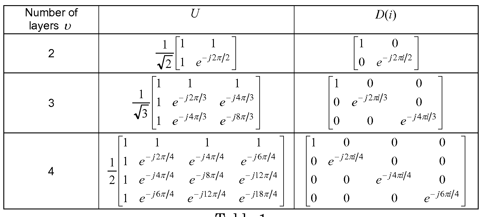
a e 1 -15-
1920856-1

Table 2
-16- -1
Number of D(i)
layers υ
1 0 0 0 0
0 e J 0 0 0
0 0 e J 0 0
0 0 0 0
0 0 0 0 e J
0 0 0 0
0 0 0
0 0 0
0 0 0
0 0 0 0
0 0 0 e
0 0 0 0 0 0
0 0 0 0 0
0 0 0 0 0
0 0 0 0 0
0 0 0 0 0
0 0 0 0 0
0 0 0 0 0
1 0 0 0 0 0 0 0
0 e J 0 0 0 0 0 0
0 0 e J 0 0 0 0 0
0 0 0 e J 0 0 0 0
0 0 0 0 e J 0 0 0
0 0 0 0 0 0 0
0 0 0 0 0 0 0
0 0 0 0 0 0 0
Table 3
[0057] In the event that the CDD may be applied to both the DM-RS and PDSCH, the large delay CDD would be equivalent to layer shifting. For example, in a four-layer transmission, on the first subcarrier of a given RB, layers 1,2,3,4 (in this order) are transmitted over 4 spatial channels; on the second subcarrier, layer 4,1,2,3 (in this order) are transmitted over 4 spatial channels, and so on. Since the DM-RS exists on the 1st, 2nd, 6th, 7th, 11th and 12th subcarriers, if the DM-RS is precoded in the same way as physical uplink shared channel (PUSCH) data, the channel estimation may be obtained as shown in Table 4.
-17-
1920856-1
Subcarrier used for 1st 2nd 6th 7th 11th 12th channel estimation
Spatial channel to 1st and 2nd and 4th and 1st and 3rd and 4th and be estimated 2nd 3rd st 2nd 4th ^st
Table 4
[0058] As shown in Table 4, the DM-RS density becomes non-uniform across spatial channels, which may cause performance degradation. To improve DM-RS channel estimation, the channel estimation may be performed as shown in Table 5.

Table 5
[0059] As shown in Table 5, DM-RS becomes uniformly distributed.
This DM-RS design may allow averaging or filtering between multiple symbols to further improve DM-RS channel estimation. In other words, in order to achieve the desired DM-RS property, the DM-RS may be precoded differently than data. For example, the large delay CDD matrix D(i) may be dropped in the DM-RS precoding. Alternatively, the DM-RS may be pre- shifted before precoding is performed if D{i) is desired.
[0060] In another example method, the data and DM-RS may be precoded separately. In this method, the DM-RS' and data to be transmitted to a WTRU may each be precoded using a different randomly selected precoder. The precoding granularity of PDSCH may be different from that of the DM- RS. The precoding granularity for the DM-RS may be either per RB or per RBG, while the precoding granularity for the PDSCH may be at the subcarrier-level, RB-level or RBG-level. Each precoder may belong to a different codebook, each containing a set of precoders. In this method, given
-18-
1920856-1
that the DM-RS and data are subject to different precoding operations, the WTRU may assume that the transmit precoding information for both the DM- RS and PDSCH are known to both the base station and the WTRU.
[0061] In another example method, the precoding on the DM-RS may be completely bypassed, (i.e., no precoding is performed on DM-RS). Alternatively, the precoding on the DM-RS may be fixed or semi-static, (e.g., the WTRU may receive the DM-RS precoding information via radio resource control (RRC) signaling or the DM-RS precoding may be fixed in the specifications).
[0062] Given that the precoder applied to the DM-RS is different from that of the PDSCH, regardless of whether or not the DM-RS is precoded, the WTRU may not assume that the estimated channel using the DM-RS is the effective channel for the PDSCH detection. In other words, the WTRU may perform a channel estimation using the DM-RS for up to eight physical transmit antennas regardless of the number of layers, (assuming that the transmit precoding information is available). Accordingly, the WTRU may need to be informed regarding the number of physical transmit antennas in addition to the number of layers. The WTRU may obtain this information using one of the example methods described herein below.
[0063] In an example method, the WTRU may be semi- statically configured via higher layer signaling or informed through downlink allocation, (i.e., via a PDCCH), regarding the number of layers and the number of physical antennas at the base station.
[0064] In another example method, the WTRU may assume that the number of DM-RS antenna ports is the same as the number of channel state information reference signal (CSI-RS) antenna ports. In the event that multiple CSI-RS configurations are used in a given cell, the WTRU may assume one CSI-RS configuration may be associated with the number of DM- RS antenna ports. The WTRU may assume that the CSI-RS configuration with a non-zero transmission power is the reference configuration for implicit derivation of the number of DM-RS antenna ports. Alternatively, the WTRU
-19-
1920856-1
may assume that one of the CSI-RS configurations with a zero transmission power may be the reference configuration for implicit derivation of the number of DM-RS antenna ports.
[0065] Alternatively, the WTRU may derive the number of DM-RS antenna ports blindly. Given that there is a 3 dB power boosting on the DM- RS when both code-division multiplexed groups are used for the DM-RS, the WTRU may blindly detect the number of DM-RS antenna ports through power detection.
[0066] In addition to random precoding, the large delay CDD together with DFT spreading may be applied at the subcarrier-level on the PDSCH. The WTRU may assume that information regarding the large delay CDD matrix, the DFT spreading matrix and the precoder are available for PDSCH detection.
[0067] The WTRU may use the channel estimates obtained from the
DM-RS and derive the effective channel using the known precoding on the DM-RS. The WTRU may then detect the PDSCH based on the knowledge of the CDD, DFT, and precoder matrices used for data.
[0068] Described herein are example methods used for heterogeneous deployments and may be applicable to other deployments as well. Hereafter, the transmission point for geographically distributed antennas refers to a remote radio head (RRH), a relay, or a macro cell.
[0069] In order to achieve spatial diversity gain in the case of geographically distributed antennas at the transmitting side, the WTRU may receive each RB within its downlink allocation from different transmission points. This technique is particularly beneficial in cases where the signals transmitted from one or multiple transmission points are experiencing sever shadowing. The spatial diversity gain is achieved through the use of a channel encoder, which is applied on multiple RBs within a transport block.
[0070] Dynamic resource scheduling may be used to achieve spatial diversity gain. In this method, the scheduler performs dynamic resource partitioning between different transmission points in all domains including
-20-
1920856-1
time, frequency, or space. Scheduling is performed based on the WTRU's channel quality feedback. More specifically, the base station may assign each transmission point a separate CSI-RS resource. The WTRU may then be configured via higher layer signaling with one or multiple CSTRS configurations to perform channel measurement and provide channel quality feedback for each transmission point. In order to facilitate frequency domain scheduling, the channel quality reports may be per-subband, where a subband is a collection of sub-carriers that have been allocated for scheduling of data. In this case, unlike the legacy systems where the CSI-RS configuration is cell- specific, the CSI-RS configuration may be WTRU- specific. The WTRU may expect the configuration of CSI-RS and/or zero-power CSI-RS and physical multicast channel (PMCH) in the same subframe of a serving cell.
[0071] Transmission point hopping may be used to achieve spatial diversity gain. In this method, the scheduler may apply a hopping scheme across transmission points while performing dynamic resource partitioning in temporal and/or frequency domains. For a given subframe, the WTRU may receive each RB from a different or randomly selected transmission point. The transmission point may belong to a set of transmission points that are allocated by the scheduler to serve the WTRU. Given that each resource allocation comprises multiple RBs, by sweeping across different transmission points, the spatial diversity gain is maximized through the channel decoding process. The chance of experiencing severe shadowing by the WTRU is substantially reduced by randomly choosing a transmission point.
[0072] Described herein is transmission point pairing or sets.
Transmission points that exhibit similar but uncorrelated channel conditions may be paired or defined in a set by the base station, for either dynamic resource scheduling or transmission point hopping. For example, transmission points in an indoor environment may be defined as belonging to the same set.
[0073] A transmission point set may be defined for transmission points which have a similar number of antennas, or similar rank capability.
-21-
1920856-1
Alternatively, a transmission point set may be associated with a particular WTRU category, or categories, that it supports. Alternatively, a transmission point set may be associated with a particular CSI-RS measurement set. The OL-SM used at each transmission point may be as described herein above or a conventional OL-SM as specified in, for example, LTE R8.
[0074] Described herein is an example method for precoding data and
DM-RS jointly for at least heterogeneous deployments. A randomly selected precoder may be applied at each RB or RBG transmitted from a different transmission point. Figure 4 shows an example OL-SM system 400 for geographically distributed transmit antennas. OL-SM system 400 may include a base station 405 defining a macro cell 405, a RRH 410, a RRH 415. a RRH 420, a WTRU 425 and a WTRU 430. When referring to random precoder selection, it should be understood that the sequence of precoder selection may be pre-defined and/or cyclical.
[0075] In one example method, the base station may define a set of cyclically defined precoders. The set of cyclically defined precoders may be cyclically rotated through a number of transmission points which use the same cell ID in a cell or may be defined for a transmission point set. In another example, the methods described herein may be applied to transmission points at the edge of the cell, to transmission points which exhibit a greater degree of interference from adjacent transmission points and/or to cells which use a different cell ID.
[0076] The precoded Pt \ vector at the th transmission point for OL-
SM, (where Pl is the number of transmit antennas at the / th transmission point ), may b
Equation (3)

where the precoding matrix Wl (i) is of size Pj x u with υ as the number of layers for transmission of the PDSCH, / = 0,1 ¾ -l with 7k¾r as the
-22-
1920856-1
number of modulation symbols to transmit per layer for a physical channel and / = 0,1,..., L - 1 with L as the number of transmission points serving the WTRU. For/? = {7, 8,..., u + 6} , the WTRU may assume that the base station cyclically assigns different precoders and different transmission points to different vectors [x(0)( ... x(t, 1)( f on the PDSCH.
[0077] The precoders used at each transmission point may belong to the same codebook or a different codebook, depending on the number of physical antennas and/or number of layers supported at each transmission point. The WTRU may not assume that the precoder applied at each RB within the multiple allocated RBs belongs to the same codebook. For example, assume that the set of transmission points which serves the WTRU 425 includes the base station 405 and two RRHs 410 and 415 and that the WTRU 425 is equipped with two antennas while the base station 405 and the two RRHs 410 and 415 are equipped with eight and four antennas, respectively. For transmission on two layers, (i.e., rank=2), the size of the precoder matrices used at the base station 405 is 8 by 2 while the size of those used at the RRHs 410 and 415 is 4 by 2.
[0078] Described herein is a combination of random precoding, CDD and
DFT spreading used for at least heterogeneous deployments. In addition to random precoding, a combination of large delay CDD and/or DFT spreading may be applied to benefit from the increased frequency selectivity. For large delay CDD with DFT spreading, precoding for spatial multiplexing using geographically distributed antennas may be defined as follows:
Equation (4)

where the precoding matrix W^i) is of size Pt v and = 0,1,..., ^ - 1 . The diagonal size- υ χ υ matrix D(i) supporting cyclic delay diversity and the size- υ χ υ matrix U are both given in Table 1 for v e {2,3,4} layers and for v e {5,6,7,8} , the matrix U and diagonal matrix D(i) may be given by Table 2
-23-
1920856-1
and Table 3, respectively.
[0079] Described herein are methods to achieve spatial multiplexing using multiple transmission points. Different layers for OL-SM may be transmitted from different transmission points. This is particularly beneficial in cases where the signals transmitted from one transmission point are spatially correlated. The high spatial correlation results in significant reduction of MIMO channel capacity and may occur when antenna spacing is insufficient or there is a lack of rich scattering environment.
[0080] By splitting the layers across the uncorrelated geographically distributed antennas, the OL-SM may be used for high rank transmissions. In other words, the number of layers for spatial multiplexing may potentially exceed the four layers specified for OL-SM in LTE Rel-8.
[0081] The application of a fixed DFT-based precoding may ensure that the channel coefficients of the antenna ports are uncorrelated. In one example method, the fixed DFT precoder may be removed from the transmission chain. For large delay CDD, precoding for spatial multiplexing using geographically distributed antennas may be defined as follows:
Equation (5)

where the precoding matrix W{i) is of size Ρ χ υ and = 0,1,..., ^ -1 . The diagonal size- υ χ υ matrix D{i) supporting cyclic delay diversity is given by Table 1 for v e {2,3,4} and Tables 2 and 3 forv e {5,6,7,8}, respectively.
[0082] Described herein are example channel quality indicator
(CQLVrank indicator (RI) reporting methods. Given that LTE R10 WTRUs and beyond may support DM-RS as part of transmission modes 8 and 9, the WTRU may be configured with transmission mode 8 or 9 or one of their descendents for OL-SM.
[0083] A number of channel quality indicator (CQI) or rank indicator
(RI) reporting methods may be defined to support OL-SM. For aperiodic CSI
-24-
1920856-1
feedback on PUSCH, reporting modes 2-0 and 3-0 from LTE R8 or RIO may be extended to transmission modes 8 and 9 or one of their descendents to support OL-SM, where reporting mode 2-0 refers to WTRU-selected subband feedback and reporting mode 3-0 refers to higher layer-configured subband feedback.
[0084] For transmission modes 8 and 9 in LTE RIO, the reporting modes
2-0 and 3-0 are supported when the WTRU is configured without precoding matrix indicator (PMI)/RI reporting or when the number of CSI-RS ports is equal to one. However, to support OL-SM, there is a need for the WTRU to feedback both CQI and rank. The WTRU may be configured with multiple CSI-RS ports for channel measurements in order to support a rank higher than one. The WTRU may report an RI as a part of reporting modes 2-0 and 3- 0. The restriction on the number of CSI-RS ports to be used by the WTRU for channel measurements under reporting modes 2-0 and 3-0 may be removed. In other words, for transmission modes 8 and 9, certain reporting modes may be supported on the PUSCH. For transmission mode 8, modes 1-2, 2-2, and 3- 1 if the WTRU is configured with PMI/RI reporting and modes 2-0 and 3-0 if the WTRU is configured without PMI reporting. For transmission mode 9, modes 1-2, 2-2, and 3-1 if the WTRU is configured with PMI/RI reporting and number of CSI-RS ports > 1 and modes 2-0 and 3-0 if the WTRU is configured without PMI reporting and number of CSI-RS ports > 1.
[0085] With respect to the WTRU procedures for reporting modes 2-0 and 3-0, for transmission modes 8 and 9, the WTRU may calculate the reported CQI values conditioned on the reported RI.
[0086] As for periodic CSI reporting using a physical uplink control channel (PUCCH), reporting modes 1-0 and 2-0 from LTE R8/10 may be extended to transmission modes 8 and 9 or one of their descendents to support OL-SM. In the context of LTE R8, reporting mode 1-0 represents wideband feedback and reporting mode 2-0 refers to WTRU-selected subband feedback.
[0087] Similar to aperiodic CSI reporting using PUSCH, there are currently some restrictions on the use of reporting modes 1-0 and 2-0 by the WTRU under transmission modes 8 and 9. To enable RI reporting and
-25-
1920856-1
configuration of more than one CSI-RS port, the WTRU may support the following periodic CSI reporting. For transmission mode 8, modes 1-1 and 2-1 if the WTRU is configured with PMI/RI reporting and modes 1-0 and 2-0 if the WTRU is configured without PMI reporting. For transmission mode 9, modes 1-1 and 2-1 if the WTRU is configured with PMI/RI reporting and the number of CSI-RS ports>l and modes 1-0 and 2-0 if the WTRU is configured without PMI reporting or the number of CSI-RS ports > 1.
[0088] With respect to the WTRU procedures for reporting modes 1-0 and 2-0, for transmission modes 8 and 9, the WTRU may calculate the CQI values conditioned on the last reported periodic RI.
[0089] In the above example, the rank report may be associated to a particular transmission point as a result of scheduling by the base station, or it may be associated with the combined rank of one or more transmission points. In the later case, the CQI reference sub-band for reporting CQI may assume the minimum of the rank of the associated transmission points. For more than two transmission points, this may by inference, imply the CQI report is for at least a 2 or greater rank.
[0090] The WTRU may transmit the CQI/RI reports using time division multiplexing (TDM) for transmission points defined in the above examples in a cyclic manner. In order to reduce the feedback overhead, a single rank report (RI) may be sent for one or multiple transmission points in a particular reporting instance.
[0091] Embodiments
[0092] 1. A method, implemented at a base station, for multiple- input multiple -output (MIMO) transmissions, the method comprising randomly selecting at least one precoder.
[0093] 2. The method embodiment 1, further comprising precoding wireless transmit/receive unit (WTRU) -specific reference signals and data using the at least one precoder.
[0094] 3. The method as in any one of the embodiments, further comprising transmitting precoded WTRU-specific reference signals and the
-26-
1920856-1
data via a plurality of antennas.
[0095] 4. The method as in any one of the embodiments, wherein the at least one precoder is one of a predefined precoder selection sequence or a base station determined precoder.
[0096] 5. The method as in any one of the embodiments, wherein a differently randomly selected precoder is used for different resource blocks (RBs).
[0097] 6. The method as in any one of the embodiments, wherein a differently randomly selected precoder is used for each predetermined number of resource blocks.
[0098] 7. The method as in any one of the embodiments, further comprising performing at least one of a large delay cyclic delay diversity (CDD) processing or discrete Fourier transform (DFT) spreading on the WTRU- specific reference signals and the data.
[0099] 8. The method as in any one of the embodiments, wherein on a condition that the CDD is applied on both the WTRU- specific reference signals and the data, the WTRU- specific references signals are precoded differently than the data.
[0100] 9. The method as in any one of the embodiments, wherein the
WTRU- specific reference signals are pre- shifted before performing the CDD.
[0101] 10. The method as in any one of the embodiments, wherein the precoding on the WTRU- specific reference signals is bypassed.
[0102] 11. The method as in any one of the embodiments, wherein the
WTRU-specific references signals are precoded differently than the data.
[0103] 12. The method as in any one of the embodiments, wherein a precoding granularity for the WTRU-specific references signals and the data are different.
[0104] 13. A method, implemented at a base station, for multiple- input multiple -output (MIMO) transmissions, the method comprising receiving channel quality feedback from a wireless transmit/receive unit (WTRU).
-27-
1920856-1
[0105] 14. The method as in any one of the embodiments, further comprising dynamically scheduling resources between transmission points in at least one domain.
[0106] 15. The method as in any one of the embodiments, further comprising transmitting data from the transmission points to the WTRU.
[0107] 16. The method as in any one of the embodiments, wherein the resources are dynamically partitioned between the transmission points.
[0108] 17. The method as in any one of the embodiments, wherein each transmission point is assigned a separate channel state information (CSI) reference signal (RS) resource.
[0109] 18. The method as in any one of the embodiments, further comprising applying a hopping scheme across the transmission points as the resources are dynamically partitioned between the transmission points.
[0110] 19. The method as in any one of the embodiments, wherein the transmission points are defined in a set.
[0111] 20. The method as in any one of the embodiments, wherein a randomly selected precoder is applied at each resource block (RB) or resource block group (RBG) transmitted from a different transmission point.
[0112] 21. The method as in any one of the embodiments, wherein different layers of data are transmitted from different transmission points.
[0113] 22. A method for multiple -input multiple -output (MIMO) transmissions, the method comprising receiving a transmission including wireless transmit/receive unit (WTRU)- specific reference signals and data via a plurality of antennas, wherein the WTRU- specific reference signals and the data are precoded using a randomly selected precoder.
[0114] 23. The method as in any one of the embodiments, further comprising performing channel estimation based on the WTRU- specific reference signals.
[0115] 24. The method as in any one of the embodiments, further comprising decoding the data based on the channel estimation.
[0116] 25. The method as in any one of the embodiments, wherein the
-28-
1920856-1
precoder belongs to a codebook which contains a set of precoders.
[0117] 26. The method as in any one of the embodiments, wherein the precoder is selected based on a predefined precoder selection sequence.
[0118] 27. The method as in any one of the embodiments, wherein the precoder is determined by a NodeB.
[0119] 28. The method as in any one of the embodiments, wherein the precoder is not known to the WTRU.
[0120] 29. The method as in any one of the embodiments, wherein a differently randomly selected precoder is applied to different resource blocks (RBs).
[0121] 30. The method as in any one of the embodiments, wherein a different precoder is applied to cyclically.
[0122] 31. The method as in any one of the embodiments, wherein a different precoder is used in every predetermined number of resource blocks.
[0123] 32. The method as in any one of the embodiments, further comprising performing at least one of a large delay cyclic delay diversity (CDD) processing or discrete Fourier transform (DFT) spreading on the WTRU- specific reference signals and the data.
[0124] 33. The method as in any one of the embodiments, wherein on a condition that the CDD is applied on both the WTRU- specific reference signals and the data, the WTRU- specific references signals are precoded differently than the data.
[0125] 34. The method as in any one of the embodiments, wherein the
WTRU- specific reference signals are pre- shifted before performing the CDD.
[0126] 35. The method as in any one of the embodiments, wherein the precoding on the WTRU- specific reference signals is bypassed.
[0127] 36. The method as in any one of the embodiments, wherein the precoding on the WTRU-specific reference signals is fixed or semi-static.
[0128] 37. A method for multiple -input multiple -output (MIMO) transmissions, the method comprising transmitting data from a plurality of transmission points to a wireless transmit/receive unit (WTRU).
-29-
1920856-1
[0129] 38. The method as in any one of the embodiments, wherein a scheduler performs dynamic resource partitioning between different transmission points.
[0130] 39. The method as in any one of the embodiments, wherein each transmission point is assigned a separate channel state information (CSI) reference signal (RS) resource.
[0131] 40. The method as in any one of the embodiments, wherein a
CSI RS configuration is WTRU- specific.
[0132] 41. The method as in any one of the embodiments,, wherein a scheduler applies a hopping scheme across transmission points.
[0133] 42. The method as in any one of the embodiments, wherein transmission points are paired or defined in a set.
[0134] 43. The method as in any one of the embodiments, wherein the transmission points in a pair or in a set are scheduled for dynamic resource scheduling or transmission point hopping.
[0135] 44. The method as in any one of the embodiments, wherein a randomly selected precoder is applied at each resource block (RB) or resource block group (RBG) transmitted from a different transmission point.
[0136] 45. The method as in any one of the embodiments, wherein the precoder is selected based on a pre-defined sequence or cycle.
[0137] 46. The method as in any one of the embodiments, wherein a different pre-defined sequence or cycle is assigned to a transmission point set.
[0138] 47. The method as in any one of the embodiments, wherein the pre-defined sequence or cycle is applied to transmission points at an edge of a cell, or for transmission points which exhibit a greater degree of interference from adjacent transmission points and/or cells which use a different cell identity.
[0139] 48. The method as in any one of the embodiments, wherein the precoders used at each transmission point belongs to a same codebook.
[0140] 49. The method as in any one of the embodiments, wherein the precoders used at each transmission point belongs to a different codebook.
-30-
1920856-1
[0141] 50. The method as in any one of the embodiments, wherein at least one of a large delay cyclic delay diversity (CDD) or discrete Fourier transform (DFT) spreading is applied.
[0142] 51. The method as in any one of the embodiments, wherein different layers of data is transmitted from different transmission points.
[0143] 52. A method for multiple -input multiple -output (MIMO) transmissions, the method comprising receiving wireless transmit/receive unit (WTRU) -specific reference signals and data that are precoded using a randomly selected precoder.
[0144] 53. The method as in embodiment 52, wherein the precoder belongs to a codebook which contains a set of precoders.
[0145] 54. The method as in any one of embodiments 52-53, wherein the precoder is selected based on a predefined precoder selection sequence.
[0146] 55. The method as in any one of embodiments 52-54, wherein a differently randomly selected precoder is applied to different resource blocks (RBs).
[0147] 56. The method as in any one of embodiments 52-55, wherein a different precoder is applied to cyclically.
[0148] 57. The method as in any one of embodiments 52-56, wherein a different precoder is used in every predetermined number of resource blocks.
[0149] 58. The method as in any one of embodiments 52-57, further comprising performing at least one of a large delay cyclic delay diversity (CDD) decoding or discrete Fourier transform (DFT) de-spreading on the WTRU- specific reference signals and the data.
[0150] 59. The method as in any one of embodiments 52-58, wherein on a condition that the CDD is applied on both the WTRU-specific reference signals and the data, the WTRU-specific references signals are precoded differently than the data.
[0151] 60. The method as in any one of embodiments 52-59, wherein the WTRU-specific reference signals are pre- shifted before performing the CDD.
-31-
1920856-1
[0152] 61. The method as in any one of embodiments 52-60, wherein the precoding on the WTRU-specific reference signals is fixed or semi-static.
[0153] 62. A method for multiple -input multiple -output (MIMO) transmissions, the method comprising a wireless transmit/receive unit
(WTRU) receiving data from a plurality of transmission points.
[0154] 63. The method as in any one of embodiments 52-60 and 62, wherein the WTRU receives on a separate channel state information (CSI) reference signal (RS) resource from each transmission point.
[0155] 64. The method as in any one of embodiments 52-60 and 62-
63, wherein the WTRU receives data from the transmission points in a hopping sequence.
[0156] 65. The method as in any one of embodiments 52-60 and 62-
64, wherein a randomly selected precoder is applied at each resource block (RB) or resource block group (RBG) transmitted from a different transmission point.
[0157] 66. The method as in any one of embodiments 52-60 and 62-
65, wherein the precoder is selected based on a pre-defined sequence or cycle.
[0158] 67. The method as in any one of embodiments 52-60 and 62-
66, wherein a different pre-defined sequence or cycle is assigned to a transmission point set.
[0159] 68. The method as in any one of embodiments 52-60 and 62-
67, wherein the precoders used at each transmission point belongs to a same codebook.
[0160] 69. The method as in any one of embodiments 52-60 and 62-
68, wherein the precoders used at each transmission point belongs to a different codebook.
[0161] 70. The method as in any one of embodiments 52-60 and 62-
69, wherein at least one of a large delay cyclic delay diversity (CDD) or discrete Fourier transform (DFT) spreading is applied.
[0162] 71. The method as in any one of embodiments 52-60 and 62-
70, wherein different layers of data is received from different transmission
-32-
1920856-1
points.
[0163] 72. The method as in any one of embodiments 52-60 and 62-
71, further comprising reporting a channel quality indicator (CQI) or a rank indicator (RI).
[0164] 73. The method as in any one of embodiments 52-60 and 62-
72, wherein the WTRU is configured with multiple channel state information (CSI) reference signal (RS) ports for channel measurements.
[0165] 74. The method as in any one of embodiments 52-60 and 62-
73, wherein the WTRU transmits the CQI or RI using time division multiplexing (TDM).
[0166] 75. An apparatus configured to implement a method as in any one of embodiments 1-74.
[0167] 76. An integrated circuit (IC) configured to implement a method as in any one of embodiments 1-74.
[0168] 77. A base station comprising a processor, transmitter in communication with the processor and a receiver in communication with the processor, each configured to implement a method as in any one of embodiments 1-74.
[0169] 78. A WTRU comprising a processor, transmitter in communication with the processor and a receiver in communication with the processor, each configured to implement a method as in any one of embodiments 1-74.
[0170] 79. A wireless entity comprising a processor, transmitter in communication with the processor and a receiver in communication with the processor, each configured to implement a method as in any one of embodiments 1-74.
[0171] Although features and elements are described above in particular combinations, one of ordinary skill in the art will appreciate that each feature or element can be used alone or in any combination with the other features and elements. In addition, the methods described herein may be implemented in a computer program, software, or firmware incorporated in a computer-
-33-
1920856-1
readable medium for execution by a computer or processor. Examples of computer-readable media include electronic signals (transmitted over wired or wireless connections) and computer-readable storage media. Examples of computer-readable storage media include, but are not limited to, a read only memory (ROM), a random access memory (RAM), a register, cache memory, semiconductor memory devices, magnetic media such as internal hard disks and removable disks, magneto -optical media, and optical media such as CD- ROM disks, and digital versatile disks (DVDs). A processor in association with software may be used to implement a radio frequency transceiver for use in a WTRU, UE, terminal, base station, RNC, or any host computer.
-34-
1920856-1
Claims
1. A method, implemented at a base station, for multiple -input multiple -output (MIMO) transmissions, the method comprising:
randomly selecting at least one precoder;
precoding wireless transmit/receive unit (WTRU) -specific reference signals and data using the at least one precoder; and
transmitting precoded WTRU- specific reference signals and the data via a plurality of antennas.
2. The method of claim 1, wherein the at least one precoder is one of a predefined precoder selection sequence or a base station determined precoder.
3. The method of claim 1, wherein a differently randomly selected precoder is used for different resource blocks (RBs).
4. The method of claim 1, wherein a differently randomly selected precoder is used for each predetermined number of resource blocks.
5. The method of claim 1, further comprising:
performing at least one of a large delay cyclic delay diversity (CDD) processing or discrete Fourier transform (DFT) spreading on the WTRU- specific reference signals and the data.
6. The method of claim 5, wherein on a condition that the CDD is applied on both the WTRU- specific reference signals and the data, the WTRU- specific references signals are precoded differently than the data.
7. The method of claim 5, wherein the WTRU-specific reference signals are pre-shifted before performing the CDD.
-35-
1920856-1
8. The method of claim 1, wherein the precoding on the WTRU- specific reference signals is bypassed.
9. The method of claim 1, wherein the WTRU-specific references signals are precoded differently than the data.
10. The method of claim 1, wherein a precoding granularity for the WTRU-specific references signals and the data are different.
11. A method, implemented at a base station, for multiple -input multiple -output (MIMO) transmissions, the method comprising:
receiving channel quality feedback from a wireless transmit/receive unit (WTRU);
dynamically scheduling resources between transmission points in at least one domain; and
transmitting data from the transmission points to the WTRU.
12. The method of claim 11, wherein the resources are dynamically partitioned between the transmission points.
13. The method of claim 11, wherein each transmission point is assigned a separate channel state information (CSI) reference signal (RS) resource.
14. The method of claim 11, further comprising:
applying a hopping scheme across the transmission points as the resources are dynamically partitioned between the transmission points.
15. The method of claim 11, wherein the transmission points are defined in a set.
-36-
1920856-1
16. The method of claim 11, wherein a randomly selected precoder is applied at each resource block (RB) or resource block group (RBG) transmitted from a different transmission point.
17. The method claim 11, wherein different layers of data are transmitted from different transmission points.
18. A method for multiple-input multiple -output (MIMO) transmissions, the method comprising:
receiving a transmission including wireless transmit/receive unit (WTRU) -specific reference signals and data via a plurality of antennas, wherein the WTRU- specific reference signals and the data are precoded using a randomly selected precoder;
performing channel estimation based on the WTRU- specific reference signals; and
decoding the data based on the channel estimation.
19. A base station, comprising:
a processor configured to randomly select at least one precoder;
the processor configured to precode wireless transmit/receive unit (WTRU) -specific reference signals and data using the at least one precoder; a transmitter in communication with the processor; and
the transmitter configured to transmit precoded WTRU- specific reference signals and the data via a plurality of antennas.
20. The base station of claim 19, wherein a differently randomly selected precoder is used for different resource blocks (RBs).
-37-
1920856-1
Priority Applications (2)
| Application Number | Priority Date | Filing Date | Title |
|---|---|---|---|
| EP12720333.9A EP2702703A2 (en) | 2011-04-29 | 2012-04-26 | Open loop spatial processing |
| JP2014508556A JP6110366B2 (en) | 2011-04-29 | 2012-04-26 | Open loop space processing |
Applications Claiming Priority (2)
| Application Number | Priority Date | Filing Date | Title |
|---|---|---|---|
| US201161480459P | 2011-04-29 | 2011-04-29 | |
| US61/480,459 | 2011-04-29 |
Publications (2)
| Publication Number | Publication Date |
|---|---|
| WO2012149178A2 true WO2012149178A2 (en) | 2012-11-01 |
| WO2012149178A3 WO2012149178A3 (en) | 2013-01-31 |
Family
ID=46052886
Family Applications (1)
| Application Number | Title | Priority Date | Filing Date |
|---|---|---|---|
| PCT/US2012/035239 Ceased WO2012149178A2 (en) | 2011-04-29 | 2012-04-26 | Open loop spatial processing |
Country Status (5)
| Country | Link |
|---|---|
| US (2) | US9331757B2 (en) |
| EP (1) | EP2702703A2 (en) |
| JP (1) | JP6110366B2 (en) |
| TW (2) | TW201705698A (en) |
| WO (1) | WO2012149178A2 (en) |
Families Citing this family (42)
| Publication number | Priority date | Publication date | Assignee | Title |
|---|---|---|---|---|
| US10886979B2 (en) | 2004-04-02 | 2021-01-05 | Rearden, Llc | System and method for link adaptation in DIDO multicarrier systems |
| US11309943B2 (en) | 2004-04-02 | 2022-04-19 | Rearden, Llc | System and methods for planned evolution and obsolescence of multiuser spectrum |
| US11394436B2 (en) | 2004-04-02 | 2022-07-19 | Rearden, Llc | System and method for distributed antenna wireless communications |
| US11451275B2 (en) | 2004-04-02 | 2022-09-20 | Rearden, Llc | System and method for distributed antenna wireless communications |
| US10985811B2 (en) | 2004-04-02 | 2021-04-20 | Rearden, Llc | System and method for distributed antenna wireless communications |
| US10425134B2 (en) | 2004-04-02 | 2019-09-24 | Rearden, Llc | System and methods for planned evolution and obsolescence of multiuser spectrum |
| EP3032754B1 (en) | 2006-03-20 | 2020-05-20 | Optis Wireless Technology, LLC | Radio communication mobile station apparatus and radio communication method |
| US9252918B2 (en) * | 2011-08-15 | 2016-02-02 | Google Technology Holdings LLC | Method and apparatus for control channel transmission and reception |
| WO2013033919A1 (en) * | 2011-09-09 | 2013-03-14 | 富士通株式会社 | Data transmission method and system, transmitter, and receiver |
| CN102404258B (en) * | 2011-11-29 | 2014-07-09 | 华为技术有限公司 | Method, system and mobile terminal for estimating downstream channels |
| JP6208409B2 (en) * | 2012-04-06 | 2017-10-04 | 株式会社Nttドコモ | User device and communication method |
| US9094145B2 (en) * | 2012-07-25 | 2015-07-28 | Nec Laboratories America, Inc. | Coordinated multipoint transmission and reception (CoMP) |
| DE202013012858U1 (en) * | 2012-08-09 | 2021-05-07 | Axel Wireless Ltd. | Capacity-centered digital distributed antenna system |
| US11190947B2 (en) | 2014-04-16 | 2021-11-30 | Rearden, Llc | Systems and methods for concurrent spectrum usage within actively used spectrum |
| US10194346B2 (en) * | 2012-11-26 | 2019-01-29 | Rearden, Llc | Systems and methods for exploiting inter-cell multiplexing gain in wireless cellular systems via distributed input distributed output technology |
| US11189917B2 (en) | 2014-04-16 | 2021-11-30 | Rearden, Llc | Systems and methods for distributing radioheads |
| US11050468B2 (en) | 2014-04-16 | 2021-06-29 | Rearden, Llc | Systems and methods for mitigating interference within actively used spectrum |
| US10164698B2 (en) | 2013-03-12 | 2018-12-25 | Rearden, Llc | Systems and methods for exploiting inter-cell multiplexing gain in wireless cellular systems via distributed input distributed output technology |
| RU2767777C2 (en) | 2013-03-15 | 2022-03-21 | Риарден, Ллк | Systems and methods of radio frequency calibration using the principle of reciprocity of channels in wireless communication with distributed input - distributed output |
| EP2996258B1 (en) | 2013-05-07 | 2019-07-31 | LG Electronics Inc. | Method for reporting channel state information for three dimensional beamforming in wireless communication system and apparatus for same |
| US9300376B2 (en) | 2013-07-05 | 2016-03-29 | Samsung Electronics Co., Ltd. | Transmitting apparatus, receiving apparatus, and control methods thereof |
| US9673957B2 (en) * | 2013-09-19 | 2017-06-06 | Telefonaktiebolaget Lm Ericsson (Publ) | System and method for providing interference characteristics for interference mitigation |
| US11290162B2 (en) | 2014-04-16 | 2022-03-29 | Rearden, Llc | Systems and methods for mitigating interference within actively used spectrum |
| CA2961696A1 (en) | 2014-09-23 | 2016-03-31 | Axell Wireless Ltd. | Automatic mapping and handling pim and other uplink interferences in digital distributed antenna systems |
| AU2015371287A1 (en) | 2014-12-23 | 2017-06-08 | Axell Wireless Ltd. | Harmonizing noise aggregation and noise management in distributed antenna system |
| AU2015380881A1 (en) | 2015-01-29 | 2017-07-06 | Sony Corporation | Device and method |
| US10367551B2 (en) | 2015-01-29 | 2019-07-30 | Intel Corporation | Precoding resource block group bundling enhancement for full dimension multi-in-multi-output |
| KR101706629B1 (en) * | 2016-01-25 | 2017-02-16 | 주식회사 이노와이어리스 | power calibration method for MIMO-OFDM transmitter |
| JP6513047B2 (en) * | 2016-03-25 | 2019-05-15 | Kddi株式会社 | Receiver for receiving mode multiplexed optical signal, and method of measuring relative delay of optical signal in the receiver |
| CN107733592B (en) | 2016-08-10 | 2020-11-27 | 华为技术有限公司 | Transmission scheme indication method, data transmission method, device and system |
| CN107769827B (en) * | 2016-08-23 | 2021-01-12 | 华为技术有限公司 | Data sending method, data receiving method, equipment and system |
| US10425970B2 (en) * | 2016-09-30 | 2019-09-24 | Qualcomm Incorporated | Precoding management for random access procedures |
| CN110419169B (en) * | 2017-03-17 | 2021-11-26 | Lg电子株式会社 | Method for applying resource bundling-based precoder in wireless communication system and apparatus therefor |
| WO2018227542A1 (en) | 2017-06-16 | 2018-12-20 | Qualcomm Incorporated | Channel state information feedback for semi-open-loop and open loop schemes |
| US10707922B2 (en) * | 2017-07-06 | 2020-07-07 | Microsoft Technology Licensing, Llc | Spatial hopping using antenna sets across multiple base stations |
| CN108880645B (en) | 2017-07-26 | 2019-08-27 | 华为技术有限公司 | Method, device and system for data transmission |
| WO2019132956A1 (en) * | 2017-12-29 | 2019-07-04 | Intel Corporation | Microelectronic assemblies |
| CN110166093B (en) * | 2018-02-13 | 2021-06-29 | 华为技术有限公司 | A transmission method and communication device |
| CN110474741B (en) * | 2018-05-11 | 2021-01-15 | 华为技术有限公司 | Communication method and device |
| KR20230034379A (en) * | 2020-07-10 | 2023-03-09 | 텔레폰악티에볼라겟엘엠에릭슨(펍) | Signaling to support enhanced NR Type II CSI feedback |
| US12567891B2 (en) * | 2020-12-28 | 2026-03-03 | Telefonaktiebolaget Lm Ericsson (Publ) | Methods for reducing overhead of NR type II channel state information feedback using angle and delay reciprocity |
| WO2023002236A1 (en) * | 2021-07-22 | 2023-01-26 | Telefonaktiebolaget Lm Ericsson (Publ) | Diversity-aware truncated layer selection for low complexity beamforming |
Family Cites Families (19)
| Publication number | Priority date | Publication date | Assignee | Title |
|---|---|---|---|---|
| ES2290530T3 (en) * | 2003-12-22 | 2008-02-16 | Telefonaktiebolaget Lm Ericsson (Publ) | MEASUREMENT METHOD FOR SPACE PROGRAMMING. |
| US7599420B2 (en) * | 2004-07-30 | 2009-10-06 | Rearden, Llc | System and method for distributed input distributed output wireless communications |
| JP5295955B2 (en) * | 2006-06-21 | 2013-09-18 | クゥアルコム・インコーポレイテッド | Method and apparatus for measuring, communicating and / or using interference information |
| JP4729537B2 (en) * | 2007-06-19 | 2011-07-20 | 株式会社エヌ・ティ・ティ・ドコモ | Base station apparatus and transmission method |
| US8009617B2 (en) * | 2007-08-15 | 2011-08-30 | Qualcomm Incorporated | Beamforming of control information in a wireless communication system |
| KR101417084B1 (en) * | 2008-07-02 | 2014-08-07 | 엘지전자 주식회사 | Reference signal transmission method for uplink transmission |
| KR101056614B1 (en) * | 2008-07-30 | 2011-08-11 | 엘지전자 주식회사 | Data transmission method in multi-antenna system |
| CN101645729A (en) * | 2008-08-08 | 2010-02-10 | 夏普株式会社 | Multi-antenna and multi-base station cooperation method and base station for downlink cellular system |
| KR101501714B1 (en) | 2008-10-14 | 2015-03-11 | 삼성전자주식회사 | Apparatus and method for reducing the over-head in a mimo wireless communication system |
| AR073834A1 (en) | 2008-10-20 | 2010-12-01 | Interdigital Patent Holdings | METHOD AND APPLIANCE TO PERFORM UPGRADING TRANSMISSION TECHNIQUES WITH MULTIPLE CONVEYORS AND REFERENCE SIGNALS |
| KR20100046338A (en) * | 2008-10-27 | 2010-05-07 | 삼성전자주식회사 | Device and method for precoding beam by channel sensitive scheduling in wireless communication system |
| US8559374B2 (en) * | 2009-02-20 | 2013-10-15 | Lg Electronics Inc. | Method and apparatus for data communication through a coordinated multi-point transmission |
| WO2010103989A1 (en) * | 2009-03-10 | 2010-09-16 | シャープ株式会社 | Wireless communication system, wireless transmitter, and control program for wireless transmitter |
| USRE49078E1 (en) * | 2009-04-23 | 2022-05-17 | Electronics And Telecommunications Research Institute | Apparatus supporting an MBMS service |
| WO2010125794A1 (en) * | 2009-04-27 | 2010-11-04 | パナソニック株式会社 | Wireless communication device and wireless communication method |
| US8830920B2 (en) * | 2009-06-17 | 2014-09-09 | Qualcomm Incorporated | Resource block reuse for coordinated multi-point transmission |
| US8923143B2 (en) * | 2009-06-29 | 2014-12-30 | Qualcomm Incorporated | Open loop channel reporting in a wireless communication system |
| US8731087B2 (en) * | 2009-06-30 | 2014-05-20 | Microsoft Corporation | Uplink MIMO transmission from mobile communications devices |
| BR112012003477A2 (en) * | 2009-08-17 | 2017-05-23 | Alcatel Lucent | "method for maintaining coherence of a precoding channel in a communication network and associated apparatus." |
-
2012
- 2012-04-26 TW TW105126287A patent/TW201705698A/en unknown
- 2012-04-26 JP JP2014508556A patent/JP6110366B2/en not_active Expired - Fee Related
- 2012-04-26 EP EP12720333.9A patent/EP2702703A2/en not_active Withdrawn
- 2012-04-26 TW TW101114836A patent/TWI580208B/en not_active IP Right Cessation
- 2012-04-26 WO PCT/US2012/035239 patent/WO2012149178A2/en not_active Ceased
- 2012-04-26 US US13/457,145 patent/US9331757B2/en not_active Expired - Fee Related
-
2016
- 2016-04-08 US US15/094,876 patent/US20160301454A1/en not_active Abandoned
Non-Patent Citations (1)
| Title |
|---|
| None |
Also Published As
| Publication number | Publication date |
|---|---|
| US9331757B2 (en) | 2016-05-03 |
| US20120275530A1 (en) | 2012-11-01 |
| US20160301454A1 (en) | 2016-10-13 |
| TW201705698A (en) | 2017-02-01 |
| JP2014514875A (en) | 2014-06-19 |
| TWI580208B (en) | 2017-04-21 |
| WO2012149178A3 (en) | 2013-01-31 |
| JP6110366B2 (en) | 2017-04-05 |
| EP2702703A2 (en) | 2014-03-05 |
| TW201251360A (en) | 2012-12-16 |
Similar Documents
| Publication | Publication Date | Title |
|---|---|---|
| US9331757B2 (en) | Open loop spatial processing | |
| US20240388404A1 (en) | Reference signal communication in a wireless network | |
| US10355759B2 (en) | Method and apparatus for multiple-input multiple-output operation | |
| KR101433296B1 (en) | Feedback for supporting su-mimo and mu-mimo operation in wireless communication | |
| JP6208309B2 (en) | Method and apparatus for estimating a channel in a wireless communication system | |
| CN104584625B (en) | The method and apparatus for sending channel state information CSI in a wireless communication system | |
| AU2011235027B2 (en) | System and methods for HSDPA multi-user MIMO operation | |
| JP2014514875A5 (en) | ||
| US11223394B2 (en) | Antenna virtualization in two-dimensional antenna array | |
| US20150195833A1 (en) | Method and apparatus for efficient feedback in a wireless communication system supporting multiple antennas | |
| US11937189B2 (en) | Robust NOMA transmission | |
| WO2012094608A2 (en) | Communicating channel state information (csi) of multiple transmission points | |
| WO2014021010A1 (en) | Base station, user equipment, communication system and communication control method | |
| AU2015234324B2 (en) | Communicating channel state information (CSI) of multiple transmission points |
Legal Events
| Date | Code | Title | Description |
|---|---|---|---|
| 121 | Ep: the epo has been informed by wipo that ep was designated in this application |
Ref document number: 12720333 Country of ref document: EP Kind code of ref document: A2 |
|
| DPE1 | Request for preliminary examination filed after expiration of 19th month from priority date (pct application filed from 20040101) | ||
| ENP | Entry into the national phase |
Ref document number: 2014508556 Country of ref document: JP Kind code of ref document: A |
|
| NENP | Non-entry into the national phase |
Ref country code: DE |
|
| WWE | Wipo information: entry into national phase |
Ref document number: 2012720333 Country of ref document: EP |