WO2012148193A2 - 통신 시스템에서 기준신호 전송 전력 제어 장치 및 방법 - Google Patents
통신 시스템에서 기준신호 전송 전력 제어 장치 및 방법 Download PDFInfo
- Publication number
- WO2012148193A2 WO2012148193A2 PCT/KR2012/003244 KR2012003244W WO2012148193A2 WO 2012148193 A2 WO2012148193 A2 WO 2012148193A2 KR 2012003244 W KR2012003244 W KR 2012003244W WO 2012148193 A2 WO2012148193 A2 WO 2012148193A2
- Authority
- WO
- WIPO (PCT)
- Prior art keywords
- srs
- power
- transmit power
- pusch
- transmission power
- Prior art date
- Legal status (The legal status is an assumption and is not a legal conclusion. Google has not performed a legal analysis and makes no representation as to the accuracy of the status listed.)
- Ceased
Links
Images


Classifications
-
- H—ELECTRICITY
- H04—ELECTRIC COMMUNICATION TECHNIQUE
- H04W—WIRELESS COMMUNICATION NETWORKS
- H04W52/00—Power management, e.g. Transmission Power Control [TPC] or power classes
- H04W52/04—Transmission power control [TPC]
- H04W52/30—Transmission power control [TPC] using constraints in the total amount of available transmission power
- H04W52/32—TPC of broadcast or control channels
- H04W52/325—Power control of control or pilot channels
-
- H—ELECTRICITY
- H04—ELECTRIC COMMUNICATION TECHNIQUE
- H04L—TRANSMISSION OF DIGITAL INFORMATION, e.g. TELEGRAPHIC COMMUNICATION
- H04L5/00—Arrangements affording multiple use of the transmission path
- H04L5/003—Arrangements for allocating sub-channels of the transmission path
- H04L5/0048—Allocation of pilot signals, i.e. of signals known to the receiver
-
- H—ELECTRICITY
- H04—ELECTRIC COMMUNICATION TECHNIQUE
- H04W—WIRELESS COMMUNICATION NETWORKS
- H04W52/00—Power management, e.g. Transmission Power Control [TPC] or power classes
- H04W52/04—Transmission power control [TPC]
- H04W52/06—TPC algorithms
- H04W52/14—Separate analysis of uplink or downlink
- H04W52/146—Uplink power control
-
- Y—GENERAL TAGGING OF NEW TECHNOLOGICAL DEVELOPMENTS; GENERAL TAGGING OF CROSS-SECTIONAL TECHNOLOGIES SPANNING OVER SEVERAL SECTIONS OF THE IPC; TECHNICAL SUBJECTS COVERED BY FORMER USPC CROSS-REFERENCE ART COLLECTIONS [XRACs] AND DIGESTS
- Y02—TECHNOLOGIES OR APPLICATIONS FOR MITIGATION OR ADAPTATION AGAINST CLIMATE CHANGE
- Y02D—CLIMATE CHANGE MITIGATION TECHNOLOGIES IN INFORMATION AND COMMUNICATION TECHNOLOGIES [ICT], I.E. INFORMATION AND COMMUNICATION TECHNOLOGIES AIMING AT THE REDUCTION OF THEIR OWN ENERGY USE
- Y02D30/00—Reducing energy consumption in communication networks
- Y02D30/70—Reducing energy consumption in communication networks in wireless communication networks
Definitions
- the present invention relates to a communication system, and more particularly, to an apparatus and method for controlling reference signal transmission power in a communication system.
- each terminal controls power of a physical channel and a signal such that different uplink physical channels and signals are received at a base station (cell).
- Uplink power control directly controls the transmit power of the terminal using an open loop scheme in which the transmit power of the terminal varies according to the downlink path loss, and an explicit power control command (TPC) command. There is a closed loop method.
- Uplink power is limited by the power that the terminal can output at maximum.
- the terminal controls the power of the physical channel and the signal within the limited available power.
- An object of the present invention is to provide an apparatus and method for assigning and controlling transmission power of a plurality of uplink physical channels and uplink reference signals simultaneously.
- an embodiment of the present invention is a method of controlling a reference signal transmission power in a communication system, and calculates transmission power of an uplink control channel and an uplink data channel transmitted simultaneously with a sounding reference signal (SRS). Making; And calculating a transmission power of the SRS, wherein an upper limit of the transmission power of the SRS is the transmission power of the uplink control channel and the uplink data channel transmitted simultaneously with the SRS at the maximum transmission power in a plurality of cells.
- the present invention provides a method for controlling a reference signal transmission power, in which transmission power is allocated in the order of re-transmitted SRS, aperiodic SRS, and periodic SRS when a plurality of SRSs are simultaneously transmitted.
- a transmission power calculation unit for calculating the transmission power of the uplink control channel, uplink data channel and SRS (Sounding Reference Signal); And a transmission power control unit controlling uplink transmission power by the transmission power calculated by the transmission power calculating unit, wherein an upper limit of the transmission power of the SRS is simultaneously transmitted with the SRS at the maximum transmission power in a plurality of cells.
- the transmission power of the control channel and the uplink data channel is the remaining power, and when a plurality of SRS is transmitted at the same time, the terminal characterized in that the transmission power is allocated in the order of re-transmitted SRS, aperiodic SRS, periodic SRS to provide.
- the transmit power of the uplink reference signal is allocated from the remaining power to efficiently control the transmit power. can do.
- transmit power may be efficiently allocated when uplink reference signals are simultaneously transmitted in a plurality of CCs.
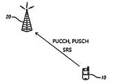
- FIG. 1 is a diagram illustrating an example of a communication system to which embodiments of the present invention can be applied;
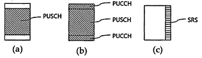
- FIG. 2 is a diagram illustrating an example of a case in which a PUCCH, a PUSCH, and a CRS may be allocated in one serving cell;
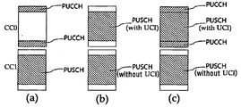
- FIG. 3 is a diagram illustrating an example where a plurality of PUCCHs and PUSCHs are simultaneously transmitted in a plurality of serving cells;
- FIG. 4 is a flowchart of a SRS transmission power control method according to an embodiment of the present invention.
- FIG. 5 is a diagram illustrating an example to which the SRS transmission power control method of FIG. 4 may be applied;
- FIG. 6 is a diagram illustrating an example of a case where a plurality of SRSs are simultaneously transmitted in a plurality of serving cells;
- FIG. 7 is a diagram illustrating another example when a plurality of SRSs are simultaneously transmitted in a plurality of serving cells.
- FIG. 8 is a block diagram of a terminal device according to an embodiment of the present invention.
- FIG. 1 illustrates a communication system to which embodiments of the present invention are applied.
- Communication systems are widely deployed to provide various communication services such as voice, packet data, and the like.
- a communication system includes a user equipment (UE) 10 and a base station 20 (BS).
- UE user equipment
- BS base station 20
- the terminal 10 or a user equipment is a comprehensive concept that means a user terminal in wireless communication.
- UE user equipment
- WCDMA Wideband Code Division Multiple Access
- LTE Long Term Evolution
- HSPA mobile station
- GSM UT
- SS subscriber station
- wireless device a wireless device that includes a user terminal, a subscriber station (SS), and a wireless device.
- a base station 20 or a cell generally refers to a station communicating with the terminal 10, and includes a Node-B, an evolved Node-B, an eNB, a Base Transceiver System (BTS), It may be called other terms such as an access point and a relay node.
- BTS Base Transceiver System
- the base station 20 or a cell is to be interpreted in a comprehensive sense indicating some areas covered by a base station controller (BSC) in a CDMA, a NodeB of a WCDMA, and the like, and a radio remote head connected to the base station )
- BSC base station controller
- a comprehensive concept of any type of device capable of communicating with one terminal such as a relay node, a sector of a macro cell, a site, or a micro cell such as a femtocell or picocell. Used as
- the terminal 10 and the base station 20 are used in a generic sense as a transmitting and receiving entity used to implement the technology or technical idea described in the present specification and are not limited to the terms or words specifically referred to.
- CDMA code division multiple access
- TDMA time division multiple access
- FDMA frequency division multiple access
- OFDMA orthogonal frequency division multiple access
- OFDM OFDM
- the present invention is a combination of the TDD (Time Division Duplex) method is transmitted using a different time, uplink transmission and downlink transmission, FDD (Frequency Division Duplex) method is transmitted using a different frequency, combining the TDD and FDD Applicable to hybrid duplexing method.
- TDD Time Division Duplex
- FDD Frequency Division Duplex
- embodiments of the present invention are applicable to asynchronous wireless communication that evolves into Long Term Evolution (LTE) and LTE-advanced through GSM, WCDMA, HSPA, and synchronous wireless communication that evolves into CDMA, CDMA-2000, and UMB.
- LTE Long Term Evolution
- WCDMA Long Term Evolution-advanced through GSM
- WCDMA Wideband Code Division Multiple Access
- HSPA High Speed Packet Access
- CDMA Code Division Multiple Access
- CDMA-2000 Code Division Multiple Access-2000
- UMB Universal Mobile Broadband
- the terminal 10 and the base station 20 may communicate in uplink and downlink.
- the base station 20 performs downlink transmission to the terminal 10.
- the base station 20 is a downlink control information and uplink data channel such as a physical downlink shared channel (PDSCH), which is a main physical channel for unicast transmission, and scheduling required for reception of the PDSCH.
- PDSCH physical downlink shared channel
- a physical downlink control channel (PDCCH) for transmitting scheduling grant information for transmission in eg, a physical uplink shared channel (PUSCH)
- PUSCH physical uplink shared channel
- the terminal 10 transmits an uplink signal to the base station 20.
- the terminal 10 includes a PUSCH, which is a main physical channel for unicast transmission, as an uplink data channel, and HARQ acknowledgment, channel status report, and uplink indicating whether a downlink transport block is successfully received as an uplink control channel.
- a physical uplink control channel (PUCCH), which is a channel used for transmitting uplink control information (UCI) including a scheduling request for resource allocation, is transmitted. Can be.
- one radioframe or radio frame consists of 10 subframes, and one subframe consists of two slots.
- the radio frame has a length of 10 ms and the subframe has a length of 1.0 ms.
- the basic unit of data transmission is a subframe unit, and downlink or uplink scheduling is performed on a subframe basis.
- One slot may have a plurality of OFDM symbols in the time domain and include at least one subcarrier in the frequency domain.
- a slot may include seven OFDM symbols (in the case of the Normal Cyclic Prefix) or six OFDM symbols in the time domain and may include 12 subcarriers in the frequency domain.
- the time-frequency domain defined as one slot may be referred to as a resource block (RB), but is not limited thereto.
- the uplink resource block to which the PUCCH is allocated is located at the edge of the total available cell bandwidth. This is for the purpose of maximizing the frequency diversity experienced by the control signaling, and for the purpose of allocating a wide transmission bandwidth to a single terminal while maintaining the single carrier characteristic of the uplink transmission by not splitting the uplink spectrum.
- the PUSCH is mapped between the edges to which the PUCCH is mapped, and the amount of contiguous spectrum possible for PUSCH transmission is maximized.
- the base station 20 includes a cell-specific reference signal (CRS), a MBSFN reference signal (Multicast / Broadcast over Single Frequency Network Reference Signal, MBSFN-RS), and a UE-specific reference signal (UE-) in downlink.
- CRS cell-specific reference signal
- MBSFN-RS Multicast / Broadcast over Single Frequency Network Reference Signal
- UE- UE-specific reference signal
- Specific Reference Signal (DM-RS) may be transmitted.
- PRS Positioning Reference Signal
- CSI Reference Signal CSI Reference Signal
- the terminal 10 may transmit a demodulation reference signal (DRS) and a sounding reference signal (SRS) in uplink.
- DRS demodulation reference signal
- SRS sounding reference signal
- the SRSs are mutually provided at regular intervals so as to transmit the uplink channel information for the entire band including not only a band to be used by each terminal 10 but also a band that the terminal 10 may use. Allows transmission on other bands that do not overlap or transmission across the entire sub-carrier band through one or more transmissions.
- the uplink reference signal may be transmitted in the last symbol of each subframe. For example, when one subframe consists of 14 symbols (Normal Cyclic Prefix), an uplink reference signal, for example, an SRS is transmitted in the 14th symbol and consists of 12 symbols (Extended Cyclic Prefix). Case) is transmitted in the 12th symbol.
- an uplink reference signal for example, an SRS is transmitted in the 14th symbol and consists of 12 symbols (Extended Cyclic Prefix). Case) is transmitted in the 12th symbol.
- the SRS sequence is generated by Equation 1 below, and the generated SRS sequence is transmitted according to the subframe configuration as shown in Table 1 after the resource mapping according to a predetermined criterion.
- U is a PUCCH sequence group number
- v is a base sequence number
- CS cyclic shift
- Table 1 above is a subframe configuration table of the FDD sounding reference signal defined in LTE, and each format (srsSubframeConfiguration) is defined as 4 bits, and the transmission period and the offset of the transmission subframe of the sounding reference signal of the terminal in the cell. It is prescribed.
- the srsSubframeConfiguration value is 8 (1000 in binary)
- Table 2 above shows the configuration of the SRSConfigurationIndex parameter (I SRS ) indicated independently to each terminal. Each terminal is instructed to the actual SRS transmission through the 10-bit parameter. For example, when SRSConfigurationIndex (I SRS ) is 40, SRS transmission is transmitted in the third subframe (I SRS- 37) every 40 subframes.
- the SRS transmitted according to the offset and the transmission period is referred to as periodic SRS (Periodic SRS).
- SRS may be transmitted aperiodically for efficient transmission of various SRSs. This is to increase the efficiency of the transmission by efficiently using the limited SRS resources by allowing the terminal with a large amount of data to transmit aperiodic SRS.
- the base station 20 may transmit a signal indicating to transmit aperiodic SRS to the terminal 10, that is, SRS triggering. Such triggering may be delivered through a DCI format.
- the terminal 10 Upon receiving the SRS triggering, the terminal 10 transmits the SRS at a frequency and a time previously scheduled with the base station 20.
- FIG. 2 illustrates an example in which a PUSCH, a PUCCH, and an SRS are allocated in a cell.
- horizontal is a subframe and vertical is a band of a cell.
- FIG. 2 (a) shows that only a PUSCH is mapped in a cell.
- the PUSCH is transmitted in the center excluding the edge of the bandwidth in the cell.
- FIG. 2 (b) shows that a PUSCH and a PUCCH are simultaneously mapped in a cell.
- the PUCCH is transmitted at the edge of the bandwidth in the cell, and the PUSCH is transmitted at the center of the bandwidth.
- FIG. 2 (c) shows that the SRS is mapped in the cell.
- the SRS is transmitted in the last symbol of the subframe.
- the transmit power of the PUSCH in the subframe i for the serving cell c is P PUSCH , c ( i )) is shown in Equation 2 below.
- the transmit power of the PUSCH in a subframe i for the serving cell c ( ) Is as shown in Equation 3 below.
- P CMAX, c (i) is the maximum transmit power of the terminal 10 in the subframe (i) for the serving cell (c), Is the linear value of P CMAX, c (i). Is a linear value of P PUCCH (i) which is a transmission power of PUCCH , which will be described later.
- P PUCCH a linear value of P PUCCH (i) which is a transmission power of PUCCH , which will be described later.
- the PUSCH transmission power is limited by the maximum transmission power in the serving cell (c) of the terminal 10.
- the PUSCH transmit power is limited by the limit value of the transmit power of the PUCCH at the maximum transmit power of the terminal 10.
- M PUSCH, c (i) is the bandwidth of the PUSCH resource allocation expressed as the number of valid resource blocks for the serving cell (c) and subframe (i). The greater the amount of resource blocks allocated, the higher the transmission power needs.
- P 0_PUSCH, c (j) is a factor for the received power that should be guaranteed in transmitting the PUSCH.
- P 0_PUSCH means the reception power required to obtain a reception signal-to-interference and noise ratio (SINR) required by the base station.
- SINR reception signal-to-interference and noise ratio
- P 0_PUSCH is a value determined based on the interference level at the base station, and the interference may vary depending on the system construction situation and may vary depending on time since the load in the network changes over time.
- J 0 for PUSCH (re) transmission for semi-persistent grant
- j 1 for PUSCH (re) transmission for dynamic scheduled grant
- random J 2 for PUSCH (re) transmission for random access response grant.
- RSRP Reference Signal Received Power
- ⁇ TF, c (i) is an offset determined by the Modulation and Coding Scheme (MCS) for the serving cell (c).
- MCS Modulation and Coding Scheme
- f c (i) is a value for directly adjusting the PUSCH transmit power through an explicit power control command.
- f c (i) is cumulative and increases or decreases by a certain amount.
- f c (i) is in UL grant.
- Is a subframe In DCI format 0 or 3 / 3A can be signaled to the PDCCH.
- accumulation is not possible to be.
- the transmit power P PUCCH (i) of the PUCCH in subframe i is expressed by Equation 4 below.
- P CMAX, c (i) is the maximum transmit power of the terminal 10 in the subframe (i) with respect to the serving cell (c), PUCCH transmit power is limited thereto.
- P 0_PUCCH consists of a common power level (P 0_NOMINAL_PUCCH ) and a terminal-specific power level (P 0_UE_PUSCH ).
- P 0_PUCCH is a factor for the received power that must be guaranteed in transmitting the PUCCH.
- P 0_PUCCH is a factor for the received power required to obtain the received SINR required by the base station, and is determined by the PUCCH format and the like.
- h (n CQI , n HARQ, n SR ) is n CQI corresponding to the number of information bits for Channel Quality Information ( CQI ), n HARQ , the number of HARQ bits transmitted in subframe (i), and subframe (i ) Is a power offset by n SR indicating whether a scheduling request (SR) is configured for the UE.
- CQI Channel Quality Information
- n HARQ the number of HARQ bits transmitted in subframe (i)
- subframe (i ) Is a power offset by n SR indicating whether a scheduling request (SR) is configured for the UE.
- the terminal is composed of one or more serving cells , Otherwise to be.
- PUCCH format 3 when the terminal is configured by a higher layer to transmit the PUCCH to two antenna ports, or when the terminal transmits more than 11 bits HARQ-ACK, to be.
- ⁇ F_PUCCH (F) is an offset determined by the PUCCH format (F).
- ⁇ TxD (F ′) is an offset considering the case where the terminal 10 is configured to transmit PUCCH in two antenna ports.
- g (i) is a value for directly adjusting the PUCCH transmit power through an explicit power control command.
- g (i) is cumulative and increases or decreases by a certain amount.
- g (i) may be included in the downlink scheduling assignment (DCI format 1A / 1B / 1D / 1 / 2A / 2 / 2B) or may be provided on a special PDCCH that simultaneously provides power control commands to multiple terminals. (DCI format 3 / 3A).
- g (i) may be used to compensate for uplink multipath fading not reflected in downlink path loss, and to compensate for a change in uplink interference not reflected in P 0_PUCCH .
- g (i) is the current PUCCH power control adjustment state
- g (0) is the initial value after reset.
- UE transmit power of SRS transmitted in subframe (i) for serving cell (c) ) Is defined as in Equation 5 below.
- P CMAX, c (i) is the maximum transmit power of the terminal 10 in the subframe (i) for the serving cell (c), the SRS transmit power is limited thereto.
- M 0 for an SRS transmission given a trigger type 0
- m 1 for an SRS transmission given a trigger type 1.
- Ks 1.25
- Ks 0, Has a size of 1.5 dB in the range [-10.5,12] dB.
- M SRS, c is the bandwidth of the SRS transmission in the subframe (i) for the serving cell (c) expressed by the number of resource blocks.
- the LTE / LTE-A system defines the use of a component carrier (CC), which is a plurality of unit carriers, as a method for extending a system requirement, that is, a bandwidth for satisfying a high data rate.
- CC component carrier
- one CC may have a bandwidth of up to 20 MHz, and resources can be allocated within 20 MHz according to a corresponding service, but this is only one embodiment according to a process of implementing a system and a bandwidth of 20 MHz or more depending on the implementation of a system. Can be set to have.
- CA carrier aggregation
- the bandwidth can be extended up to 100 MHz to support quality of service.
- the assignable frequency band that can be determined by the component carriers may be contiguous or non-contiguous depending on the scheduling of the actual CA.
- a plurality of CCs may be divided into one Primary Component Carrier (PCC) and one or more Secondary Component Carriers (SCC).
- PCC Primary Component Carrier
- SCC Secondary Component Carriers
- the primary carrier (PCC) may be called a primary cell
- the secondary component carrier (SCC) may be called a secondary cell.
- the PCC may serve as a core carrier for managing the aggregated CCs, and the remaining SCs may serve as additional frequency resources for providing more data rates.
- the PUCCH and PUSCH including the UCI for the control of the uplink in the uplink can be transmitted only through the major carrier (PCC), the PUCCH and PUSCH including the UCI is transmitted through the sub-component carrier (SCC) It may not be.
- an index (serving cell index) (ServCellIndex) may be assigned to the plurality of component carriers.
- a serving cell index (ServCellIndex) of each component carrier may be specified as 0 to 4.
- CC0 having a serving cell index of 0 may be a major carrier (PCC)
- CC1 to CC4 having a serving cell index of 1 to 4 may be a subcomponent carrier (SCC).
- FIG. 3 illustrates a case where PUCCH and / or PUSCH are transmitted in a plurality of component carriers and a single subframe.
- two component carriers CC0 and CC1 are shown in FIG. 3, a plurality of component carriers may exist as an example.
- the first CC CC0 is a major carrier PCC and the second CC CC1 is a subcomponent carrier SCC.
- FIG. 3 (a) illustrates a case where a PUCCH is transmitted on a first component carrier CC0 and a PUSCH is transmitted on a second component carrier CC1.
- the power of the terminal is preferentially allocated to the transmit power of the PUCCH, and among the remaining powers, the transmit power of the PUSCH is allocated.
- the transmit power of the PUSCH satisfies Equation 6 below.
- Equation 6 Is a linear value of the PUSCH transmit power defined in Equation 4, Is a linear value of the PDSCH transmit power defined in Equation 2 or 3.
- the maximum transmission power of the terminal in the entire number of cells Is a linear value of.
- W (i) is a scaling factor and has a range of 0 ⁇ w (i) ⁇ 1.
- (b) illustrates a case where a PUSCH having uplink control information UCI is transmitted on a first component carrier CC0 and a PUSCH having no UCI is transmitted on a second component carrier CC1.
- PUSCH with UCI has higher importance than PUSCH without UCI. Therefore, the power of the terminal is preferentially allocated to the PUSCH having the UCI, and the transmission power of the PUSCH having no UCI among the remaining powers is allocated.
- the transmit power of a PUSCH without UCI satisfies Equation 7 below.
- Equation 7 j is an index of a serving cell transmitting a PUSCH having UCI, and c (c ⁇ j) except for a j value is an index of a serving cell transmitting a PUSCH having no UCI.
- the maximum transmission power of the terminal in the entire number of cells Is a linear value of.
- W (i) is a scaling factor and has a range of 0 ⁇ w (i) ⁇ 1.
- (c) illustrates a case where a PUSCH having a PUCCH and a UCI are simultaneously transmitted on a first component carrier CC0 and a PUSCH having no UCI is transmitted on a second component carrier CC1.
- the PUCCH has a higher importance than the PUSCH, and among the PUSCHs, a PUSCH having a UCI has a higher importance than a PUSCH having no UCI. Therefore, the power of the UE will be allocated in the order of PUCCH, PUSCH with UCI, and PUSCH without UCI.
- the transmit power of the PUCCH is calculated by Equation 4.
- the transmit power of the PUSCH with UCI satisfies Equation 8 below.
- Equation 8 the first and second rows represent Equation 3 as a linear value.
- Equation 8 shows that PUCCH transmit power is allocated first in the total transmit power for a plurality of cells, and transmit power of a PUSCH having UCI is allocated at the remaining power.
- the total transmit power for multiple cells Is the maximum transmit power () for the serving cell (j) Since it will be greater than or equal to)
- the result of Equation 8 may be the same as the result of Equation 3.
- Equation 9 The maximum transmission power of the terminal in the entire number of cells Is a linear value of Is a linear value of the PUCCH transmit power defined in Equation 4, Is a linear value of the PUSCH transmit power with UCI defined in Equation 8, Is a linear value of the PUSCH transmit power without the UCI defined in equation (2).
- W (i) is a scaling factor and has a range of 0 ⁇ w (i) ⁇ 1.
- the priority of power allocation may be in the order of PUCCH, PUSCH, SRS.
- PUCCH is for uplink control and may have the highest priority.
- PUSCH may have priority after PUCCH.
- a PUSCH having a UCI may have priority over a PUSCH having no UCI.
- SRS is used for scheduling resource blocks in uplink afterwards and has a lower priority than PUCCH and PUSCH. This is summarized in Table 2 below.
- FIG. 4 is a flowchart illustrating a method of determining SRS transmit power according to an embodiment of the present invention.
- FIG. 5 is an example to which the method of FIG. 4 is applied, and a PUCCH 501 is transmitted on a first component carrier CC0, a PUSCH 502 is transmitted on a second component carrier CC1, and a third component carrier CC2. In this case, the SRS 503 is transmitted.
- the linear value of the available power P available to the UE for uplink transmission ( The initial value of) is the total transmit power for multiple cells ( Linear value of (Step S401).
- PUCCH transmission power is allocated first (step S403).
- PUCCH transmit power is calculated by equation (4).
- the linear value of the available power Is the linear value of the previous available power ( Linear value of the PUCCH transmit power at ) Is updated to the reduced value (step S404).
- the linear value of the available power ( ) Is the linear value of the PUCCH transmit power ( ) Remains undecreased.
- step S405 If the PUSCH 502 transmission is required in the subframe (i) (YES in step S405), the PUSCH transmission power is allocated next (step S406).
- the transmit power of the PUSCH with UCI is calculated by equation (2) or equation (8). That is, when the PUCCH transmit power is not allocated, the transmit power of the PUSCH having UCI may be calculated by Equation 2, and when the PUCCH transmit power is allocated, the transmit power of the PUSCH having UCI may be calculated by Equation 8. .
- the transmit power of the PUSCH without UCI may be calculated by Equation 2 or 3 and may be limited by the condition of Equation 6, 7 or 9. That is, when a PUSCH is not transmitted simultaneously with a PUCCH in one cell, the transmit power of the PUSCH without UCI is calculated by Equation 2, and when the PUSCH is transmitted simultaneously with the PUCCH, the transmit power of the PUSCH without UCI is expressed by Equation 2. Calculated by equation 3.
- the transmit power of the PUSCH without UCI is limited by Equation 6
- the transmit power of the PUSCH without UCI is expressed by Equation 7
- the transmission power of the PUSCH having no UCI is limited by Equation 9.
- the linear value of the available power ( ) Is the linear value of the PUSCH transmit power ( ) Is updated to the reduced value (step S407).
- the linear value of the available power ( ) Is the sum of the linear values of the PUSCH transmit power ( ) Is updated with the subtracted value.
- the linear value of the available power ( ) Is the linear value of the PUSCH transmit power ( ) Remains undecreased.
- step S402 when transmission of PUCCH and PUSCH is required (YES in step S402, YES in step S405), the linear value of the available power ( ) Is the initial value ( In this case, the linear value of the PUCCH transmission power and the linear value of the PUSCH transmission power are subtracted, and (2) when transmission of the PUCCH is required and transmission of the PUSCH is not required (YES in step S402, NO in step S405), Linear value of available power ( ) Is the initial value ( ), The linear value of the PUCCH transmission power is subtracted, and (3) when the PUCCH transmission is not required and the PUSCH transmission is required (NO in step S402, YES in step S405), the linear value of available power ( ) Is the initial value ( ), The linear value of the PUSCH transmission power is subtracted, and (4) when the transmission of the PUCCH and the PUSCH is not required (NO in step S402, NO in step S405), the linear value of available power ( ) I
- SRS transmission power is allocated (step S408). Details of the SRS transmit power allocation step (step S408) will be described later.
- the threshold a is a value determined by Equation 5 or a value multiplied by a predetermined constant smaller than 1 (for example, 0.9).
- the total transmit power of the plurality of component carriers is the maximum transmit power across the plurality of cells.
- the scaling factor w (i) (0 ⁇ w (i) ⁇ 1) may be used to reduce the PUSCH transmission power of each component carrier. This is because retransmission is possible when a packet error occurs in PUSCH transmission, and the influence of the packet error is also limited to the corresponding subframe.
- SRS is unlikely to change the transmission power flexibly like PUSCH. Since the SRS is a signal transmitted for the purpose of channel estimation, more than a certain level of transmission power is required for accurate channel estimation in the presence of noise. In addition, the effect of the SRS channel estimation is a plurality of subframes up to a certain period to obtain the channel information of the band.
- the transmit power of the UE is determined by the maximum transmit power across the plurality of cells. ), It is undesirable to change the SRS transmit power below a certain level.
- the terminal 10 transmits the SRS with the transmission power calculated as described above (step S410). However, if the transmission power of the SRS is less than the predetermined threshold (a) (NO in step S409), the terminal 10 cancels the SRS transmission (step S411).
- the SRS is transmitted to estimate channel quality over a wideband, and can combine multiple narrowband SRS transmissions to cover the frequency band of interest. If one narrowband SRS transmission fails, the base station 20 must wait to receive the failed narrowband SRS to estimate the wideband channel quality, and the effect of the failed SRS transmission is of interest as well as the narrowband in which the SRS transmission failed. Spread across the frequency band. In addition, the effect of the SRS channel estimation is a plurality of subframes up to a certain period to obtain the channel information of the band.
- the terminal 10 transmits the canceled SRS at the next SRS transmission opportunity.
- SRS retransmission of the terminal 10 may follow a predetermined rule known to the terminal 10 and the base station 20. Alternatively, the SRS retransmission of the terminal 10 may occur at a time when the terminal 10 may determine, and information about the SRS retransmission may be transmitted from the terminal 10 to the base station 20. Alternatively, the SRS retransmission of the terminal 10 may be performed according to the instruction of the base station 20 that has not received the SRS.
- the transmit power of the retransmitted SRS will be assigned priority over the transmit power of other SRSs other than the retransmission, as will be described later.
- step S408 of FIG. 4 for allocating SRS transmit power will be described in detail.
- Equation 10 the first row and the second row represent equations 5 as linear values.
- the maximum transmission power of the terminal in the entire number of cells Is a linear value of Is a linear value of the PUCCH transmit power defined in Equation 4, Is the sum of the linear values of the respective PUSCH transmit powers defined by Equations 2 or 3 and Equations 6-9.
- the PUSCH includes a PUSCH with UCI and a PUSCH without UCI.
- Equation 10 shows that PUCCH and PUSCH transmit powers are allocated first in the total transmit powers for a plurality of cells, and SRS transmit powers are allocated in the remaining powers.
- a plurality of component carriers and a plurality of SRSs may be transmitted in a single subframe.
- FIG. 6 illustrates an example of a PUSCH 601 being transmitted on a first CC CC0, an SRS 602 being transmitted on a second CC CC1, and an SRS 603 on a third CC CC2. Shows the case where is transmitted. In this case, two SRSs 602 and 603 are transmitted in the same subframe.
- a PUSCH 701 is initially transmitted on a first component carrier CC0, a PUSCH 702 is transmitted on a second component carrier CC1, and an SRS (on a third component carrier CC2). 703 is transmitted. After the transmission powers of the PUSCHs 701 and 702 are allocated, transmission of the SRS 703 fails because the transmission power of the SRS 703 is insufficient, and the SRS 706 is retransmitted at the next transmission opportunity. In the subframe where the SRS 706 is retransmitted, the PUSCH 704 is transmitted on the first CC CC0 and the SRS 705 is transmitted on the second CC CC1. In this case, two SRSs 705 and 706 are transmitted in the same subframe.
- Transmission of a plurality of SRSs may occur in the following cases.
- SRSs may be simultaneously transmitted in a plurality of CCs.
- Aperiodic SRS transmission may overlap with periodic SRS transmission of another cell.
- SRS is transmitted in order to estimate channel quality in wideband and may combine multiple narrowband SRS transmissions to cover the frequency band of interest. If one narrowband SRS transmission fails, the base station 20 must wait to receive the failed narrowband SRS to estimate the wideband channel quality, and the effect of the failed SRS transmission is of interest as well as the narrowband in which the SRS transmission failed. Spread across the frequency band. Therefore, when multiple SRSs are transmitted at the same time, the resent SRSs have the highest priority.
- aperiodic SRS transmission occurs when the base station 20 commands the terminal 10 for SRS transmission without waiting for periodic SRS transmission. Therefore, aperiodic SRS transmissions have priority over periodic SRS transmissions.
- the transmit power of the periodic SRS is allocated.
- the SRS transmitted from the subcarrier (PCC) has priority over the SRS transmitted from the subcarrier (SCC).
- SCC subcarrier
- Priority in SRS transmit power allocation has the order of retransmission SRS, aperiodic SRS, periodic SRS,
- SRSs transmitted from CCs having a low serving cell index have priority.
- Equation 11 the first row and the second row are the same as Equation 10.
- the maximum transmission power of the terminal in the entire number of cells Is a linear value of Is a linear value of the PUCCH transmit power defined in Equation 4, Is the sum of the linear values of the respective PUSCH transmit powers defined by Equations 2 or 3 and Equations 6-9.
- the PUSCH includes a PUSCH with UCI and a PUSCH without UCI. Is the sum of the linear values of the transmit power of the retransmitted SRS transmitted at the serving cell index lower than the retransmitted SRS for which the transmit power is to be obtained.
- One retransmission SRS or retransmission SRS is transmitted in the primary cell (PCC) Is 0.
- Equation 11 indicates that the transmit power of the retransmission SRS transmitted in the cell having the PUCCH, the PUSCH and the lower serving cell index is allocated first in the total transmit power for the plurality of cells, and the retransmission SRS transmit power is allocated in the remaining power. .
- Equation 12 the linear value of the aperiodic SRS transmission power ( ) Is expressed by Equation 12 below.
- Equation 12 the first row and the second row are the same as Equation 10.
- the maximum transmission power of the terminal in the entire number of cells Is a linear value of Is a linear value of the PUCCH transmit power defined in Equation 4, Is the sum of the linear values of the respective PUSCH transmit powers defined by Equations 2 or 3 and Equations 6-9.
- the PUSCH includes a PUSCH with UCI and a PUSCH without UCI.
- One aperiodic SRS or aperiodic SRS is transmitted in the primary cell (PCC) Is 0.
- Equation 12 is first assigned transmit power of aperiodic SRS transmitted in a cell with PUCCH, PUSCH, retransmission SRS and lower serving cell index in the total transmit power for multiple cells, and aperiodic SRS transmit power in remaining power. Indicates that this is assigned.
- Equation 13 the first row and the second row are the same as Equation 10.
- the maximum transmission power of the terminal in the entire number of cells Is a linear value of Is a linear value of the PUCCH transmit power defined in Equation 4, Is the sum of the linear values of the respective PUSCH transmit powers defined by Equations 2 or 3 and Equations 6-9.
- the PUSCH includes a PUSCH with UCI and a PUSCH without UCI.
- One periodic SRS or periodic SRS is transmitted in a primary cell (PCC) Is 0.
- Equation (13) is first assigned the transmit power of a periodic SRS transmitted in a cell with PUCCH, PUSCH, retransmitted SRS, aperiodic SRS, and lower serving cell index at the total transmit power for multiple cells, and the periodic SRS at remaining power. Indicates that transmit power is allocated.
- the SRS transmission power is determined by Equation 10.
- the transmission power of the retransmission SRS is determined by Equation 11
- the transmission power of the aperiodic SRS is determined by Equation 12
- the transmission power of the periodic SRS is Equation 13 Determined by
- FIG. 8 is a functional block diagram of a terminal device according to an embodiment of the present invention.
- the terminal device 800 may include a transmit power calculator 801 and a transmit power calculator 801 that calculate transmit power of PUCCH, PDCCH, and SRS in each serving cell.
- the transmission power control unit 802 controls the uplink transmission power of the terminal device 800 with the transmission power calculated by.
- the transmit power calculator 801 allocates transmit power in the order of PUCCH, PUSCH, and SRS.
- the transmit power of PUCCH, PUSCH, and SRS in each cell is the maximum transmit power in one cell.
- the transmit power of the PUSCH and SRS in the entire cell is determined by the maximum transmit power ( Limited by).
- the transmit power of an SRS is determined by the maximum transmit power across multiple cells. Transmit power of the PUCCH and the PUSCH is limited by the remaining power.
- the transmit power calculator 801 allocates transmit power in the order of retransmitted SRS, aperiodic SRS, and periodic SRS.
- the transmit power calculator 801 first allocates transmit power to SRSs transmitted from a serving cell having a low serving cell index (ServCellIndex).
- the transmit power of each SRS is limited by the transmit power allocated to PUCCH, PUSCH, and other higher priority SRS.
- the terminal device 800 may further include an SRS power determination unit 803 that determines whether the transmission power of the SRS calculated by the transmission power calculation unit 801 is greater than or equal to a predetermined threshold value.
- an SRS power determination unit 803 determines that the transmission power of the SRS calculated by the transmission power calculation unit 801 is smaller than a predetermined threshold value
- the transmission power control unit 802 is calculated by the transmission power calculation unit 801. Even if the linear value of the transmission power of the SRS is not 0, the transmission of the SRS is cancelled.
- FIG. 9 is a flowchart illustrating an SRS receiving method of a base station according to an embodiment of the present invention.
- the base station 20 receives an uplink signal from the terminal (step S901).
- the uplink signal received by the base station 20 includes uplink control information through the PUCCH, uplink data through the PUSCH, and a reference signal.
- the reference signal may include an SRS.
- the base station 20 determines whether the SRS is received when the SRS is to be received by a predetermined rule or an appointment with the terminal 10 (step S902). As described above, when the power that can be allocated by the terminal 10 for transmitting the SRS is smaller than a predetermined threshold, the terminal 10 does not transmit the SRS, and thus the base station 20 may receive the SRS. none.
- the base station 20 waits until the terminal 10 retransmits the SRS failed to transmit (step S903).
- the terminal 10 may be based on a predetermined rule that both the terminal 10 and the base station 20 know.
- the terminal 10 retransmits the SRS, it is determined by the terminal 10, and information about the SRS retransmission of the terminal 10 may be transmitted from the terminal 10 to the base station 20.
- the base station 20 may transmit an instruction for SRS retransmission to the terminal 10. The uplink scheduling of the base station 20 waits until the SRS that fails to receive is received.
- FIG. 10 is a functional block diagram of a base station according to an embodiment of the present invention.
- the base station 1000 includes an uplink receiver 1001, an SRS receiver 1002, and an uplink scheduler 1003.
- the uplink receiver 1001 receives an uplink signal from the terminal.
- the uplink signal received by the uplink receiver 1001 includes uplink control information through the PUCCH, uplink data through the PUSCH, and a reference signal including the SRS.
- the SRS extractor 1002 extracts an SRS from an uplink signal received by the uplink receiver 1001.
- the SRS extracted by the SRS extractor 1002 is used to set uplink scheduling in the uplink scheduler 1003.
- the SRS extractor 1002 waits until the terminal can receive the SRS retransmitted.
- the terminal retransmits the SRS may be based on a predetermined rule known to both the terminal and the base station.
- information about the SRS retransmission of the terminal may be transmitted from the terminal to the base station.
- the base station may transmit an indication for SRS retransmission to the terminal.
- the SRS extractor 1002 waits for uplink scheduling of the uplink scheduler 1003 until an SRS that fails to receive is received.
Landscapes
- Engineering & Computer Science (AREA)
- Signal Processing (AREA)
- Computer Networks & Wireless Communication (AREA)
- Mobile Radio Communication Systems (AREA)
- Transmitters (AREA)
Abstract
본 발명은 무선 통신 시스템에 관한 것으로서, 무선 통신 시스템 내에서 단말의 상향링크 기준신호 전송 전력 제어에 관한 것이다.
Description
본 발명은 통신 시스템에 관한 것으로서, 보다 상세하게는 통신 시스템에서 기준신호 전송 전력 제어 장치 및 방법에 관한 것이다.
통신 시스템에서, 각 단말은 서로 다른 상향링크 물리채널들과 신호들이 기지국(셀)에서 수신되도록 물리채널 및 신호의 전력을 제어한다.
상향링크 전력 제어는 단말의 전송 전력이 하향링크 경로 손실에 따라 달라지는 개루프 방식과, 명시적 전력 제어 명령(power control command), 즉 TPC(Transmit Power Control) 명령를 사용하여 단말의 전송 전력을 직접 제어하는 폐루프 방식이 있다.
상향링크 전력은 단말이 최대로 출력할 수 있는 전력에 의해 제한된다. 단말은 한정된 가용 전력 내에서 물리채널 및 신호의 전력을 제어한다.
본 발명은, 다수의 상향링크 물리채널과 상향링크 기준신호가 동시에 전송될 때, 이들의 전송 전력을 할당 제어하는 장치 및 방법을 제공하는 것을 목적으로 한다.
상술한 목적을 달성하기 위해 본 발명의 일 실시예는, 통신 시스템에서 기준신호 전송 전력 제어 방법으로서, SRS(Sounding Reference Signal)와 동시에 전송되는 상향링크 제어채널 및 상향링크 데이터채널의 전송 전력을 계산하는 단계; 및 SRS의 전송 전력을 계산하는 단계를 포함하고, 상기 SRS의 전송 전력의 상한값은 다수의 셀 전체에서 최대 전송 전력에서 상기 SRS와 동시에 전송되는 상기 상향링크 제어채널 및 상향링크 데이터채널의 전송 전력이 할당되고 남은 전력이며, 복수의 SRS가 동시에 전송되는 경우, 재전송되는 SRS, 비주기적 SRS, 주기적 SRS의 순서로 전송 전력이 할당되는 것을 특징으로 하는 기준신호 전송 전력 제어 방법을 제공한다.
본 발명의 다른 실시예는, 상향링크 제어채널, 상향링크 데이터채널 및 SRS(Sounding Reference Signal)의 전송 전력을 계산하는 전송 전력 계산부; 및 상기 전송 전력 계산부에서 계산된 전송 전력으로 상향링크 전송 전력을 제어하는 전송 전력 제어부를 포함하고, SRS의 전송 전력의 상한값은 다수의 셀 전체에서 최대 전송 전력에서 상기 SRS와 동시에 전송되는 상향링크 제어채널 및 상향링크 데이터채널의 전송 전력이 할당되고 남은 전력이며, 복수의 SRS가 동시에 전송되는 경우, 재전송되는 SRS, 비주기적 SRS, 주기적 SRS의 순서로 전송 전력이 할당되는 것을 특징으로 하는 단말을 제공한다.
상술한 본 발명에 따르면, 상향링크 제어채널, 상향링크 데이터채널과 같은 상향링크 물리채널에 전송 전력이 먼저 할당되고, 남은 전력으로부터 상향링크 기준신호의 전송 전력이 할당되기 때문에 전송 전력을 효율적으로 제어할 수 있다. 또한, 다수의 요소 반송파에서 상향링크 기준신호가 동시에 전송될 때 전송 전력이 효율적으로 할당될 수 있다.
도 1은 본 발명의 실시예들이 적용될 수 있는 통신 시스템의 일예를 도시하는 도면,
도 2는 하나의 서빙 셀 내에 PUCCH, PUSCH 및 CRS가 할당될 수 있는 경우의 예를 도시하는 도면,
도 3은 다수의 서빙 셀에서 복수의 PUCCH 및 PUSCH가 동시에 전송되는 경우의 예를 도시하는 도면,
도 4는 본 발명의 일 실시예에 따른 SRS 전송 전력 제어 방법의 흐름도,
도 5는 도 4의 SRS 전송 전력 제어 방법이 적용될 수 있는 일예를 도시하는 도면,
도 6은 다수의 서빙 셀에서 복수의 SRS가 동시에 전송되는 경우의 일예를 도시하는 도면,
도 7은 다수의 서빙 셀에서 복수의 SRS가 동시에 전송되는 경우의 다른 예를 도시하는 도면, 및
도 8은 본 발명의 일 실시예에 따른 단말 장치의 블록도.
이하, 본 발명의 일부 실시 예들을 예시적인 도면을 통해 상세하게 설명한다. 각 도면의 구성요소들에 참조부호를 부가함에 있어서, 동일한 구성요소들에 대해서는 비록 다른 도면상에 표시되더라도 가능한 한 동일한 부호를 가지도록 하고 있음에 유의해야 한다. 또한, 본 발명을 설명함에 있어, 관련된 공지 구성 또는 기능에 대한 구체적인 설명이 본 발명의 요지를 흐릴 수 있다고 판단되는 경우에는 그 상세한 설명은 생략한다.
도 1은 본 발명의 실시 예들이 적용되는 통신 시스템을 도시한다.
통신 시스템은 음성, 패킷 데이터 등과 같은 다양한 통신 서비스를 제공하기 위해 널리 배치된다.
도 1을 참조하면, 통신 시스템은 단말(10; User Equipment, UE) 및 기지국(20;Base Station, BS)을 포함한다.
본 명세서에서의 단말(10) 또는 UE(User Equipment)는 무선 통신에서의 사용자 단말을 의미하는 포괄적 개념으로서, WCDMA 및 LTE, HSPA 등에서의 UE는 물론, GSM에서의 MS(Mobile Station), UT(User Terminal), SS(Subscriber Station), 무선기기(wireless device) 등을 모두 포함하는 개념으로 해석되어야 할 것이다.
기지국(20) 또는 셀(cell)은 일반적으로 단말(10)과 통신하는 지점(station)을 말하며, 노드-B(Node-B), eNB(evolved Node-B), BTS(Base Transceiver System), 액세스 포인트(Access Point), 릴레이 노드(Relay Node) 등 다른 용어로 불릴 수 있다.
본 명세서에서 기지국(20) 또는 셀(cell)은 CDMA에서의 BSC(Base Station Controller), WCDMA의 NodeB 등이 커버하는 일부 영역을 나타내는 포괄적인 의미로 해석되어야 하며, 기지국과 연결된 RRH(Radio Remote Head), 릴레이 노드(relay node), 매크로 셀의 섹터(sector), 사이트(site), 기타 펨토셀, 피코셀 등과 같은 마이크로 셀 등 하나의 단말과 통신할 수 있는 모든 형태의 장치를 의미하는 포괄적인 개념으로 사용된다.
본 명세서에서 단말(10)과 기지국(20)은 본 명세서에서 기술되는 기술 또는 기술적 사상을 구현하는데 사용되는 송수신 주체로 포괄적인 의미로 사용되며 특정하게 지칭되는 용어 또는 단어에 한정되지 않는다.
통신 시스템에 적용되는 다중 접속 기법에는 제한이 없으며, 본 발명은 CDMA(Code Division Multiple Access), TDMA(Time Division Multiple Access), FDMA(Frequency Division Multiple Access), OFDMA(Orthogonal Frequency Division Multiple Access), OFDM-FDMA, OFDM-TDMA, OFDM-CDMA와 같은 다양한 다중 접속 기법에 적용 가능하다.
또한, 본 발명은 상향링크 전송 및 하향링크 전송은 서로 다른 시간을 사용하여 전송되는 TDD(Time Division Duplex) 방식, 서로 다른 주파수를 사용하여 전송되는 FDD(Frequency Division Duplex) 방식, TDD와 FDD를 결합한 하이브리드 듀플렉싱(Hybrid Duplexing) 방식에 적용 가능하다.
구체적으로, 본 발명의 실시예는 GSM, WCDMA, HSPA를 거쳐 LTE(Long Term Evolution) 및 LTE-advanced로 진화하는 비동기 무선 통신과, CDMA, CDMA-2000 및 UMB로 진화하는 동기식 무선 통신 분야 등에 적용될 수 있다. 이러한 본 발명은 특정한 무선 통신 분야에 한정되거나 제한되어 해석되어서는 아니되고, 본 발명의 사상이 적용될 수 있는 모든 기술분야를 포함하는 것으로 해석되어야 할 것이다.
도 1을 다시 참조하면, 단말(10)과 기지국(20)은 상향링크 및 하향링크 통신할 수 있다.
기지국(20)은 단말(10)로 하향링크 전송을 수행한다. 기지국(20)은 유니캐스트 전송(unicast transmission)을 위한 주 물리 채널인 물리 하향링크 공유채널(Physical Downlink Shared Channel, PDSCH), 그리고 PDSCH의 수신에 필요한 스케줄링 등의 하향링크 제어 정보 및 상향링크 데이터 채널(예를 들면 물리 상향링크 공유채널(Physical Uplink Shared Channel, PUSCH))에서의 전송을 위한 스케줄링 승인 정보를 전송하기 위한 물리 하향링크 제어채널(Physical Downlink Control Channel, PDCCH)을 전송할 수 있다. 이하에서는, 각 채널을 통해 신호가 송수신 되는 것을 해당 채널이 송수신되는 형태로 기재하기로 한다.
단말(10)은 기지국(20)으로 상향링크 신호를 전송한다. 단말(10)은 상향링크 데이터채널로서 유니캐스트 전송을 위한 주 물리 채널인 PUSCH, 그리고 상향링크 제어채널로서 하향링크 전송 블록이 성공적으로 수신되었는지 여부를 알려주는 HARQ acknowledgement, 채널 상태 보고 및 상향링크에서 데이터를 송신하고자 할 경우 자원 할당을 요구하는 스케줄링 요청을 포함하는 상향링크 제어 정보(Uplink Control Information, UCI)를 전송하기 위해 사용되는 채널인 물리 상향링크 제어채널(Physical Uplink Control Channel, PUCCH)을 전송할 수 있다.
한편, 하나의 라디오프레임(Radioframe) 또는 무선 프레임은 10개의 서브프레임(subframe)으로 구성되고, 하나의 서브프레임은 2개의 슬롯으로 구성된다. 무선 프레임은 10ms의 길이를 갖고, 서브프레임은 1.0ms의 길이를 갖는다. 일반적으로, 데이터 송신의 기본 단위는 서브프레임 단위가 되고, 서브프레임 단위로 하향링크 또는 상향링크의 스케줄링이 이루어진다.
하나의 슬롯은 시간 영역에서 복수의 OFDM 심볼을 갖고 주파수 영역에서 적어도 하나의 부반송파(subcarrier)를 포함할 수 있다. 예를 들면, 슬롯은 시간 영역에서 7개(Normal Cyclic Prefix인 경우) 또는 6개(Extended Cyclic Prefix인 경우)의 OFDM 심볼을 포함하고 주파수 영역에서 12개의 부반송파를 포함할 수 있다. 이렇게 하나의 슬롯으로 정의되는 시간-주파수 영역을 자원 블록(Resource Block, RB)로 부를 수 있으나, 이에 한정되는 것은 아니다.
PUCCH가 할당되는 상향링크 자원 블록은 전체 가용한 셀 대역폭의 가장 가장자리에 위치한다. 이는 제어 시그널링이 겪는 주파수 다이버시티를 극대화하기 위한 목적, 그리고 상향링크 스펙트럼을 쪼개지 아니하여 상향링크 전송의 단일 반송파 특성을 유지하면서 단일 단말에게 넓은 전송 대역폭을 할당하는 목적을 위해서이다. PUSCH는 PUCCH가 맵핑된 가장자리 사이에 맵핑되고, PUSCH 전송에 가능한 연속된 스펙트럼의 양은 극대화된다.
기지국(20)은 하향링크에서 셀-고유 기준 신호(Cell-Specific Reference Signal, CRS), MBSFN 기준 신호(Multicast/Broadcast over Single Frequency Network Reference Signal, MBSFN-RS), 단말-고유 기준 신호(UE-Specific Reference Signal, DM-RS), 위치 기준 신호(Positioning Reference Signal, PRS), 및 CSI 기준 신호(CSI Reference Signal, CSI-RS)를 전송할 수 있다.
단말(10)은 상향링크에서 복조 기준 신호(Demodulation Reference Signal, DRS) 및 사운딩 기준 신호(Sounding Reference Signal, SRS)를 전송할 수 있다.
이 중, SRS는 각 단말(10)이 사용할 대역뿐만 아니라 단말(10)이 사용할 가능성이 있는 대역까지 포함하는 전 대역에 대한 상향 링크 채널 정보를 기지국(20)에 전달할 수 있도록 하기 위해 일정한 주기로 서로 겹쳐지지 않는 다른 대역에 전송되거나 한 번 또는 그 이상의 전송을 통해 전 서브-캐리어 대역에 걸쳐서 송신되도록 한다.
상향링크 기준신호는 각 서브프레임의 가장 마지막 심볼에 송신될 수 있다. 예를 들면, 하나의 서브프레임이 14개의 심볼로 구성될 경우(Normal Cyclic Prefix인 경우) 상향링크 기준신호, 일례로 SRS는 14번째 심볼에서 송신되고, 12개의 심볼로 구성된 경우(Extended Cyclic Prefix인 경우) 12번째 심볼에서 송신된다.
현재의 LTE 표준에 의하면, SRS 시퀀스는 아래 수학식 1에 의하여 생성되며, 생성된 SRS 시퀀스는 소정의 기준에 의한 리소스 매핑을 거친 후 아래 표 1과 같은 서브프레임 설정에 따라 송신된다.
[수학식 1]

여기서,  는 기준신호 시퀀스의 길이이고,
  이고, u는 PUCCH 시퀀스 그룹번호이고, v는 베이스 시퀀스 번호이며, 싸이클릭 시프트(Cyclic Shift; CS)
  이다.
이다.  는 0 내지 7 중 하나의 정수 값으로서 상위 계층에 의하여 각 UE마다 설정된다.
[표 1]

위의 표 1은 LTE에 정의되어 있는 FDD 사운딩 기준신호의 서브프레임 설정표로서, 각 형식(srsSubframeConfiguration)은 4비트로 정의되며 해당 셀 내의 단말의 사운딩 기준신호의 송신주기와 송신 서브프레임의 오프셋을 규정하고 있다.
즉, srsSubframeConfiguration 값이 8인 경우(바이너리로는 1000)를 예로 들면, 셀 내의 단말들은 5 서브프레임마다 2, 3번째 서브프레임에 SRS를 송신할 수 있음을 의미한다.
[표 2]

위의 표 2는 각 단말에게 독립적으로 지시되는 SRSConfigurationIndex 파라미터(ISRS)의 구성을 표로 나타낸 것이다. 각 단말은 상기 10 비트 파라미터를 통해 실제 SRS 전송을 지시받는다. 예를 들어 SRSConfigurationIndex(ISRS)이 40인 경우 SRS 전송은 40 서브프레임마다 3번째 서브프레임(ISRS-37)에 전송된다.
SRS의 실제 전송이 상술한 바와 같이 오프셋과 송신 주기에 따라 전송되는 SRS를 주기적 SRS(Periodic SRS)라 한다.
다양한 SRS의 효율적 전송을 위하여 SRS는 비주기적으로 송신될 수 있다. 이는 전송할 데이터 양이 많은 단말에게 비주기 SRS를 전송하게 하여 제한된 SRS 자원을 효율적으로 사용하고 주파수 선택 스케줄링을 이용하여 전송의 능률을 높이기 위함이다. 기지국(20)은 단말(10)로 비주기적 SRS를 송신할 것을 지시하는 신호, 즉 SRS 트리거링(triggering)을 전송할 수 있다. 이러한 트리거링은 DCI 포맷을 통해 전달될 수 있다. SRS 트리거링을 수신한 단말(10)은 기지국(20)과 미리 약속된 주파수 및 시간에 SRS를 전송한다.
이하에서는 상향링크에서 단말(10)의 전력 제어에 대하여 기재한다.
도 2는 셀 내에 PUSCH, PUCCH, SRS가 할당된 예를 도시한다. 도 2에서 가로는 서브프레임이고 세로는 셀의 대역이다.
도 2(a)는 셀 내에 PUSCH만이 맵핑된 것을 도시한다. 도 2(a)를 참조하면, PUSCH는 셀에서 대역폭의 가장자리를 제외한 가운데에서 전송된다.
도 2(b)는 셀 내에 PUSCH와 PUCCH가 동시에 맵핑된 것을 도시한다. 도 2(b)를 참조하면, PUCCH는 셀에서 대역폭의 가장자리에서 전송되고, PUSCH는 대역폭의 가운데에서 전송된다.
도 2(c)는 셀 내에 SRS가 맵핑된 것을 도시한다. 도 2(c)를 참조하면, SRS는 서브프레임의 가장 마지막 심볼에서 전송된다.
도 2(a)에서와 같이, 단말(10)이 서빙 셀(serving cell)(c)에서 PUSCH를 전송하는 경우, 서빙 셀(c)에 대한 서브프레임(i)에서 PUSCH의 전송 전력( P
PUSCH,c(i) )은 다음의 수학식 2와 같다.
[수학식 2]

도 2(b)에서와 같이, 단말(10)이 서빙 셀(serving cell)(c)에서 PUCCH와 함께 PUSCH를 전송하는 경우, 서빙 셀(c)에 대한 서브프레임(i)에서 PUSCH의 전송 전력(  )은 다음의 수학식 3과 같다.
[수학식 3]

수학식 2 및 3에서, PCMAX,c(i)는 서빙 셀(c)에 대해 서브프레임(i)에서 단말(10)의 최대 전송 전력이고,  는 PCMAX,c(i)의 선형 값(linear value)이다.
  는 PUCCH의 전송 전력인 PPUCCH(i)의 선형 값으로서, 이에 대하여는 후술될 것이다. 수학식 2를 참조하면, PUSCH를 PUCCH와 동시에 전송하지 않는 경우, PUSCH 전송 전력은 단말(10)의 서빙 셀(c)에서 최대 전송 전력에 의해 제한된다. 수학식 3을 참조하면, PUSCH를 PUCCH와 동시에 전송하는 경우, PUSCH 전송 전력은 단말(10)의 최대 전송 전력에서 PUCCH의 전송 전력을 제한 값에 의해 제한된다.
MPUSCH,c(i)는 서빙 셀(c) 및 서브프레임(i)에 대해 유효한 자원 블록의 수로 표현되는 PUSCH 자원 할당의 대역폭이다. 자원 블록이 할당되는 양이 많아질수록 더 높은 송신 전력을 요구한다.
P0_PUSCH,c(j)는 반-정적 베이스 레벨(semi-static base level)로서, 공통 전력 레벨(  )과 단말-특정 전력 레벨(
  )로 구성된다(
  =
=  +
+  ).
).
다르게 말하자면, P0_PUSCH,c(j)는 PUSCH를 전송함에 있어 보장되어야 하는 수신 전력에 대한 인자이다. P0_PUSCH는 기지국에서 요구되는 수신 SINR(Signal-to-interference and noise ratio)을 얻기 위해 필요한 수신 전력을 의미한다. P0_PUSCH는 기지국에서 간섭 레벨에 기초하여 결정되는 값이고, 간섭은 시스템 구축 상황에 따라 달라질 수도 있고 망 내의 부하가 시간에 따라 변하므로 시간에 따라서 달라질 수도 있다.
준-지속적(semi-persistent) 승인(grant)에 대한 PUSCH (재)전송에 대해 j=0이고, 동적으로 스케줄링되는(dynamic scheduled) 승인에 대한 PUSCH (재)전송에 대해 j=1이며, 랜덤 액세스 응답(random access response) 승인에 대한 PUSCH (재)전송에 대해 j=2이다.
αc(j)는 경로 손실을 보상하는 정도를 나타낸다. αc(j)가 1이면 경로 손실이 완전히 보상되는 것을 의미하고, αc(j)가 1보다 작으면 경로 손실이 완전히 보상되지 않은 것을 의미한다. j=0 또는 1일 때, αc(j) ∈ {0, 0.4, 0.5, 0.6, 0.7, 0.8, 0.9, 1}이고, j=2일 때 αc(j)=1이다.
PLc는 서빙 셀(c)에 대해 단말(10)에서 계산된 하향링크 경로-손실(path loss) 추정값으로서, PLc = (기준 신호 전송 전력 기준 신호 수신 전력(Reference Signal Received Power, RSRP))의 식으로 결정될 수 있다.
ΔTF,c(i)는 서빙 셀(c)에 대해 MCS(Modulation and Coding Scheme)에 의해 결정되는 오프셋이다.
fc(i)는 명시적인 전력 제어 명령을 통해 직접적으로 PUSCH 전송 전력을 조절하기 위한 값이다. fc(i)는 누적값으로서, 특정 양 만큼 증가 또는 감소시킨다. fc(i)는 상향링크 스케줄링 승인(UL grant)에 들어있다.
보다 상세하게는,  의 식으로 표현될 수 있다.
  는 서브프레임
  에서 DCI 포맷 0 또는 3/3A로 PDCCH로 신호될 수 있다. 누적이 가능하지 않을 때
  이다.
이다.
서빙 셀(c)이 프라이머리 셀(primary cell)인 경우, 서브프레임(i)에서 PUCCH의 전송 전력( P
PUCCH
(i) )은 다음의 수학식 4와 같다.
[수학식 4]

수학식 4에서, PCMAX,c(i)는 서빙 셀(c)에 대해 서브프레임(i)에서 단말(10)의 최대 전송 전력이고, PUCCH 전송 전력은 이에 제한된다.
P0_PUCCH는 공통 전력 레벨( P0_NOMINAL_PUCCH )과 단말-특정 전력 레벨( P0_UE_PUSCH )로 구성된다.
다르게 말하자면, P0_PUCCH는 PUCCH를 전송함에 있어 보장되어야 하는 수신 전력에 대한 인자이다. P0_PUCCH는 기지국에서 요구되는 수신 SINR을 얻기 위해 필요한 수신 전력에 대한 인자이며, PUCCH 포맷 등에 의해 결정된다.
PLc는 서빙 셀(c)에 대해 단말(10)에서 계산된 하향링크 경로-손실(path loss) 추정값으로서, PLc = (기준 신호 전송 전력 기준 신호 수신 전력(Reference Signal Received Power, RSRP))의 식으로 결정된다.
h(nCQI, nHARQ, nSR)는 CQI(Channel Quality Information)에 대한 정보 비트의 수에 해당하는 nCQI, 서브프레임(i)으로 전송되는 HARQ 비트의 수인 nHARQ, 및 서브프레임(i)이 단말에 대한 SR(Scheduling Request)로 구성되었는지 여부를 나타내는 nSR에 의한 전력 오프셋이다.
PUCCH 포맷 1, 1a 및 1b에 대하여  이다.
이다.
채널 선택을 갖는 PUCCH 포맷 1b에 대하여, 단말이 하나 이상의 서빙 셀로 구성되는 경우  이고, 다른 경우
  이다.
이다.
PUCCH 포맷 2, 2a, 2b이고 normal cyclic prefix인 경우,  이다.
이다.
PUCCH 포맷 2이고 extended cyclic prefix인 경우,  이다.
이다.
PUCCH 포맷 3에 대하여, 단말이 2개 안테나 포트로 PUCCH를 전송하도록 상위 계층에 의해 구성되는 경우, 또는 단말이 11 비트 이상의 HARQ-ACK를 전송하는 경우,  이다.
이다.
PUCCH 포맷 3에 대하여, 다른 경우  이다.
이다.
ΔF_PUCCH(F)는 PUCCH 포맷(F)에 의해 결정되는 오프셋이다.
ΔTxD(F’)는 단말(10)이 2개 안테나 포트에서 PUCCH를 전송하도록 구성되는 경우를 고려한 오프셋이다.
g(i)는 명시적인 전력 제어 명령을 통해 직접적으로 PUCCH 전송 전력을 조절하기 위한 값이다. g(i)는 누적값으로서, 특정 양 만큼 증가 또는 감소시킨다. g(i)는 하향링크 스케줄링 할당에 포함되어 있거나(DCI 포맷 1A/1B/1D/1/2A/2/2B), 여러 개의 단말들에 전력 제어 명령을 동시에 제공하는 특수한 PDCCH 상으로도 제공될 수 있다(DCI 포맷 3/3A). g(i)는 하향링크 경로 손실에 반영되지 않은 상향링크 다중 경로 페이딩을 보상하기 위한 용도, P0_PUCCH에 반영되지 않은 상향링크 간섭의 변화를 보상하는 용도로 사용될 수 있다.
보다 상세하게는,  의 식으로 표현될 수 있다. g(i)는 현재 PUCCH 전력 제어 조절 상태이고, g(0)는 리셋 후 초기값이다.
서빙 셀(c)에 대한 서브프레임(i)에서 전송되는 SRS의 단말 전송 전력(  )은 다음의 수학식 5와 같이 규정된다.
[수학식 5]

수학식 5에서, PCMAX,c(i)는 서빙 셀(c)에 대해 서브프레임(i)에서 단말(10)의 최대 전송 전력이고, SRS 전송 전력은 이에 제한된다.


MSRS,c는 자원 블록의 수로 표현되는 서빙 셀(c)에 대한 서브 프레임(i)에서 SRS 전송의 대역폭이다.
fc(i)는 수학식 2 및 3에서 규정된 바와 같다.
P0_PUSCH,c(j) 및 αc(j)는 수학식 2 및 3에서 규정된 바와 같고, j=1이다.
한편, LTE/LTE-A 시스템은, 시스템 요구 사항, 즉 높은 데이터 전송률을 만족시키기 위한 대역폭을 확장하기 위한 방안으로서, 다수개의 단위 반송파인 요소 반송파(Component Carrier, CC)의 사용을 정의하고 있다. 여기에서, 하나의 CC는 최대 20MHz의 대역폭을 가질 수 있으며, 해당 서비스에 따라 20MHz 이내에서 자원 할당이 가능하지만, 이는 시스템을 구현하는 과정에 따른 일 실시예일 뿐이고 시스템의 구현에 따라 20MHz 이상의 대역폭을 가지도록 설정할 수 있다. 또한, 요소 반송파를 다수개 묶어 하나의 시스템 대역으로 사용하는 반송파 집적(Carrier Aggregation, CA) 기술의 사용을 정의할 수 있다.
일 예로서, 20MHz의 최대 대역폭을 갖는 요소 반송파 5개를 사용할 경우, 최대 100MHz까지 대역폭을 확장하여 서비스 품질을 지원할 수 있다. 요소 반송파들에 의해 결정될 수 있는 할당 가능한 주파수 대역은 실제 CA의 스케줄링에 따라 연속적(contiguous)일 수도 있고 불연속적(non-contiguous)일 수도 있다.
CA 환경에서, 다수개의 요소 반송파를 효율적으로 관리하기 위하여, 복수의 요소 반송파를 하나의 주요소 반송파(Primary Component Carrier, PCC)와 하나 이상의 부요소 반송파(Secondary Component Carrier, SCC)로 나눌 수 있다. 또는, 주요소 반송파(PCC)는 프라이머리 셀(primary cell), 부요소 반송파(SCC)는 세컨더리 셀(secondary cell)로 불릴 수 있다.
주요소 반송파(PCC)는 집적되어 있는 전체 요소 반송파들을 관리하는 핵심 반송파의 역할을 담당하고, 나머지 부요소 반송파(SCC)는 더 많은 전송률을 제공하기 위한 추가적인 주파수 자원을 제공하는 역할을 담당할 수 있다. 예를 들면, 상향 링크에서 상향 링크의 제어를 위한 UCI를 포함하는 PUCCH 및 PUSCH는 주요소 반송파(PCC) 통해서만 전송될 수 있고, 부요소 반송파(SCC)를 통해서는 UCI를 포함하는 PUCCH 및 PUSCH가 전송되지 않을 수 있다.
또는, 다수개의 요소 반송파를 효율적으로 관리하기 위하여, 복수개의 요소 반송파에 인덱스(서빙 셀 인덱스)(ServCellIndex)를 지정할 수 있다. 예를 들면, 5개의 요소 반송파(CC0, CC1, CC2, CC3, CC4)가 집적된 경우, 각 요소 반송파의 서빙 셀 인덱스(ServCellIndex)를 0 내지 4로 지정할 수 있다. 예를 들면, 상기 예에서 서빙 셀 인덱스가 0인 CC0는 주요소 반송파(PCC)이고, 서빙 셀 인덱스가 1 내지 4인 CC1 내지 CC4는 부요소 반송파(SCC)일 수 있다.
도 3은 다수개의 요소 반송파와 단일 서브프레임에서 PUCCH 및/또는 PUSCH가 전송되는 경우를 도시한다. 도 3에서 2개의 요소 반송파(CC0 및 CC1)가 도시되었지만, 이는 예시를 위한 것으로서 다수개의 요소 반송파가 존재할 수 있다. 도 3의 예에서 제1요소 반송파(CC0)는 주요소 반송파(PCC)이고 제2요소 반송파(CC1)는 부요소 반송파(SCC)이다.
도 3에서 (a)는 제 1 요소 반송파(CC0)에서 PUCCH가 전송되고 제 2 요소 반송파(CC1)에서 PUSCH가 전송되는 경우를 도시한다.
PUCCH는 상향링크 제어 정보를 포함하고 있어 PUSCH에 비해 높은 중요도를 갖는다. 그러므로, 단말의 전력은 PUCCH의 전송 전력에 우선적으로 할당되고, 남는 전력 중에서 PUSCH의 전송 전력이 할당된다. PUSCH의 전송 전력은 다음의 수학식 6을 만족한다.
[수학식 6]

수학식 6에서,  는 수학식 4에서 규정된 PUSCH 전송 전력의 선형값이고,
  는 수학식 2 또는 3에서 규정된 PDSCH 전송 전력의 선형값이다.


그리고, w(i)는 스케일링 팩터로서, 0≤w(i)≤1의 범위를 갖는다.
수학식 6은 다수의 셀에 대한 전체 전송 전력에서 PUCCH 전송 전력이 먼저 할당되고, 남는 전력에서 PUSCH 전송 전력이 할당됨을 나타낸다. PUCCH 전송 전력을 할당하고 남는 전력이 충분한 경우, PUSCH 전송 전력으로는 수학식 2 또는 3에서 규정된 값이 할당될 것이다(w(i)=1). 그러나, 충분하지 않은 경우, 실제 PUSCH 전송 전력으로는 수학식 2 또는 3에서 규정된 값에 스케일링 팩터 w(i)가 곱해져서 감소된 값이 할당될 것이다(w(i)<1).
도 3에서 (b)는 제 1 요소 반송파(CC0)에서 상향링크 제어 정보(UCI)를 갖는 PUSCH가 전송되고 제 2 요소 반송파(CC1)에서 UCI를 갖지 않는 PUSCH가 전송되는 경우를 도시한다.
UCI를 갖는 PUSCH는 UCI를 갖지 않는 PUSCH에 비해 높은 중요도를 갖는다. 그러므로, 단말의 전력은 UCI를 갖는 PUSCH에 우선적으로 할당되고, 남은 전력 중에서 UCI를 갖지 않는 PUSCH의 전송 전력이 할당된다. UCI를 갖지 않는 PUSCH의 전송 전력은 다음의 수학식 7을 만족한다.
[수학식 7]

수학식 7에서, j는 UCI를 갖는 PUSCH를 전송하는 서빙 셀의 인덱스이고, j 값을 제외한 c(c≠j)는 UCI를 갖지 않는 PUSCH를 전송하는 서빙 셀의 인덱스이다. 즉,  는 수학식 2 또는 3에 의해 계산되는 UCI를 갖는 PUSCH의 전송 전력의 선형값이고,
  는 수학식 2 또는 3에 의해 계산되는 UCI를 갖지 않는 PUSCH의 전송 전력의 선형값이다.


그리고, w(i)는 스케일링 팩터로서, 0≤w(i)≤1의 범위를 갖는다.
수학식 7은 다수의 셀에 대한 전체 전송 전력에서 UCI를 갖는 PUSCH 전송 전력이 먼저 할당되고, 남은 전력에서 UCI를 갖지 않는 PUSCH 전송 전력이 할당됨을 나타낸다. UCI를 갖는 PUSCH 전송 전력을 할당하고 남는 전력이 충분한 경우, UCI를 갖지 않는 PUSCH 전송 전력으로는 수학식 2 또는 3에서 규정된 값이 할당될 것이다(w(i)=1). 그러나, 충분하지 않은 경우, 실제 UCI를 갖지 않는 PUSCH 전송 전력으로는 수학식 2 또는 3에서 규정된 값에 스케일링 팩터 w(i)가 곱해져서 감소된 값이 할당될 것이다(w(i)<1).
도 3에서 (c)는 제 1 요소 반송파(CC0)에서 PUCCH 및 UCI를 갖는 PUSCH가 동시에 전송되고 제 2 요소 반송파(CC1)에서 UCI를 갖지 않는 PUSCH가 전송되는 경우를 도시한다.
이러한 경우, PUCCH가 PUSCH에 비해 높은 중요도를 갖고, PUSCH 중에서는 UCI를 갖는 PUSCH가 UCI를 갖지 않는 PUSCH에 비해 높은 중요도를 갖는다. 그러므로, 단말의 전력은 PUCCH, UCI를 갖는 PUSCH, UCI를 갖지 않는 PUSCH의 순서로 할당될 것이다.
PUCCH의 전송 전력은 수학식 4에 의해 계산된다.
UCI를 갖는 PUSCH의 전송 전력은 다음의 수학식 8을 만족한다.
[수학식 8]

수학식 8에서 첫 번째 행과 두 번째 행은 수학식 3을 선형값으로 표현한 것이다.
세 번째 행에서  는 단말이 다수의 셀 전체에서 최대 전송 전력
  의 선형값이고,
  는 수학식 4에서 규정된 PUCCH 전송 전력의 선형값이다.
수학식 8은 다수의 셀에 대한 전체 전송 전력에서 PUCCH 전송 전력이 먼저 할당되고, 남는 전력에서 UCI를 갖는 PUSCH의 전송 전력이 할당됨을 나타낸다. 한편, 다수의 셀에 대한 전체 전송 전력(  )은 서빙 셀(j)에 대한 최대 전송 전력(
  )보다 크거나 같을 것이기 때문에, 수학식 8의 결과는 수학식 3의 결과와 같을 수 있다.
그리고, UCI를 갖지 않는 PUSCH의 전송 전력은 다음의 수학식 9를 만족한다.
[수학식 9]

수학식 9에서,  는 단말이 다수의 셀 전체에서 최대 전송 전력
  의 선형값이고,
  는 수학식 4에서 규정된 PUCCH 전송 전력의 선형값이며,
  는 수학식 8에서 규정된 UCI를 갖는 PUSCH 전송 전력의 선형값이고,
  는 수학식 2에서 규정된 UCI를 갖는 않는 PUSCH 전송 전력의 선형값이다.
그리고, w(i)는 스케일링 팩터로서, 0≤w(i)≤1의 범위를 갖는다.
수학식 9는 다수의 셀에 대한 전체 전송 전력에서 PUCCH 전송 전력 및 UCI를 갖는 PUSCH 전송 전력이 먼저 할당되고, 남은 전력에서 UCI를 갖지 않는 PUSCH 전송 전력이 할당됨을 나타낸다. UCI를 갖는 PUSCH 전송 전력을 할당하고 남는 전력이 충분한 경우, UCI를 갖지 않는 PUSCH 전송 전력으로는 수학식 2에서 규정된 값이 할당될 것이다(w(i)=1). 그러나, 충분하지 않은 경우, 실제 UCI를 갖지 않는 PUSCH 전송 전력으로는 수학식 2에서 규정된 값에 스케일링 팩터 w(i)가 곱해져서 감소된 값이 할당될 것이다(w(i)<1).
다음으로, 다수개의 요소 반송파와 단일 서브프레임에서 SRS가 PUCCH, PUSCH 및/또는 다른 SRS가 동시에 전송되는 경우를 고려한다.
전력 할당의 우선 순위는 PUCCH, PUSCH, SRS의 순서일 수 있다. PUCCH는 상향링크 제어를 위한 것으로서 가장 높은 우선권을 가질 수 있다. PUSCH는 PUCCH 다음으로 우선권을 가질 수 있다. PUSCH 중에서는 UCI를 갖는 PUSCH가 UCI를 갖지 않는 PUSCH보다 우선권을 가질 수 있다. SRS는 이후의 상향링크에서 자원 블록의 스케줄링을 위해 사용되는 것으로서 PUCCH 및 PUSCH보다는 낮은 우선권을 갖는다. 이를 정리하면 다음의 표 2와 같다.
[표 2]

도 4는 본 발명의 일 실시예에 따른 SRS 전송 전력을 결정하는 방법을 도시하는 순서도이다.
도 5는 도 4의 방법이 적용되는 일예로서 제 1 요소 반송파(CC0)에서 PUCCH(501)가 전송되고, 제 2 요소 반송파(CC1)에서 PUSCH(502)가 전송되며, 제 3 요소 반송파(CC2)에서 SRS(503)가 전송되는 경우를 도시한다.
도 4를 참조하면, 단말이 상향링크 전송을 위해 이용할 수 있는 가용 전력(P)의 선형값(  )의 초기값은 다수의 셀에 대한 전체 전송 전력(
  )의 선형값(
  )이다(S401 단계).
서브프레임(i)에 PUCCH(501) 전송이 요구되는 경우(S402 단계에서 예), 우선 PUCCH 전송 전력이 할당된다(S403 단계). PUCCH 전송 전력은 수학식 4에 의해 계산된다. 그리고, 가용 전력의 선형값(  )은 이전의 가용 전력의 선형값(
  )에서 PUCCH 전송 전력의 선형값(
  )이 감해진 값으로 갱신된다(S404 단계).
서브프레임(i)에 PUCCH 전송이 요구되지 않는 경우(S402 단계에서 아니오), 가용 전력의 선형값(  )은 PUCCH 전송 전력의 선형값(
  )이 감해지지 않은 값으로 유지된다.
서브프레임(i)에 PUSCH(502) 전송이 요구되는 경우(S405 단계에서 예), 다음으로 PUSCH 전송 전력이 할당된다(S406 단계).
UCI를 갖는 PUSCH의 전송 전력은 수학식 2 또는 수학식 8에 의해 계산된다. 즉, PUCCH 전송 전력이 할당되지 않은 경우 UCI를 갖는 PUSCH의 전송 전력은 수학식 2에 의해 계산되고, PUCCH 전송 전력이 할당된 경우 UCI를 갖는 PUSCH의 전송 전력은 수학식 8에 의해 계산될 수 있다.
UCI를 갖지 않는 PUSCH의 전송 전력은 수학식 2 또는 수학식 3에 의해 계산되고 수학식 6, 수학식 7 또는 수학식 9의 조건에 의해 제한될 수 있다. 즉, 한 셀 내에서 PUSCH가 PUCCH와 동시에 전송되지 않는 경우 UCI를 갖지 않는 PUSCH의 전송 전력은 수학식 2에 의해 계산되고, PUSCH가 PUCCH와 동시에 전송되는 경우 UCI를 갖지 않는 PUSCH의 전송 전력은 수학식 3에 의해 계산된다. 다른 셀에서 PUCCH가 전송되는 경우 UCI를 갖지 않는 PUSCH의 전송 전력은 수학식 6에 의해 제한되고, 다른 셀에서 UCI를 갖는 PUSCH가 전송되는 경우 UCI를 갖지 않는 PUSCH의 전송 전력은 수학식 7에 의해 제한되며, 다른 셀에서 PUCCH 및 UCI를 갖는 PUSCH가 전송되는 경우 UCI를 갖지 않는 PUSCH의 전송 전력은 수학식 9에 의해 제한된다.
그리고, 가용 전력의 선형값(  )은 PUSCH 전송 전력의 선형값(
  )이 감해진 값으로 갱신된다(S407 단계). 다수개의 PUSCH가 전송되는 경우, 가용 전력의 선형값(
  )은 PUSCH 전송 전력의 선형값의 합(
  )이 감해진 값으로 갱신된다.
한편, 서브프레임(i)에 PUSCH 전송이 요구되지 않는 경우(S405 단계에서 아니오), 가용 전력의 선형값(  )은 PUSCH 전송 전력의 선형값(
  )이 감해지지 않은 값으로 유지된다.
즉, (1) PUCCH와 PUSCH의 전송이 요구되는 경우(S402 단계에서 예, S405 단계에서 예), 가용 전력의 선형값(  )은 초기값(
  )에서 PUCCH 전송 전력의 선형값 및 PUSCH 전송 전력의 선형값이 감해진 값이고, (2) PUCCH의 전송이 요구되고 PUSCH의 전송이 요구되지 않는 경우(S402 단계에서 예, S405 단계에서 아니오), 가용 전력의 선형값(
  )은 초기값(
  )에서 PUCCH 전송 전력의 선형값이 감해진 값이며, (3) PUCCH의 전송이 요구되지 않고 PUSCH의 전송이 요구되는 경우(S402 단계에서 아니오, S405 단계에서 예), 가용 전력의 선형값(
  )은 초기값(
  )에서 PUSCH 전송 전력의 선형값이 감해진 값이고, (4) PUCCH 및 PUSCH의 전송이 요구되지 않는 경우(S402 단계에서 아니오, S405 단계에서 아니오), 가용 전력의 선형값(
  )은 초기값(
  )을 유지한다.
다음으로, SRS 전송 전력이 할당된다(S408 단계). SRS 전송 전력 할당 단계(S408 단계)의 상세는 후술될 것이다.
다음으로, SRS의 전송 전력이 소정의 임계값(a) 이상인지 여부가 판단된다(S409 단계). 임계값(a)은 수학식 5에 의해 결정되는 값 또는 이 값에 1보다 작은 소정의 상수(예를 들면, 0.9)를 곱한 값이다.
수학식 6, 수학식 7 및 수학식 9에서, 복수의 요소 반송파의 전체 전송 전력이 다수의 셀 전체에서 최대 전송 전력(  )을 초과할 때 스케일링 팩터(w(i))(0≤w(i)≤1)를 이용하여 각 요소 반송파의 PUSCH 전송 전력을 낮출 수 있다. 이는 PUSCH 전송에서 패킷 오류가 발생할 때 재전송이 가능하고, 또한 패킷 오류가 미치는 영향도 해당 서브프레임에 제한되기 때문이다.
이에 비하여, SRS는 PUSCH와 같이 유연하게 전송 전력에 변화를 주기 어렵다. SRS는 채널 추정을 목적으로 전송되는 신호이기 때문에 잡음이 존재하는 환경에서 정확한 채널 추정을 위해서는 일정한 수준 이상의 전송 전력이 필요하다. 또한, SRS 채널 추정이 미치는 영향은 해당 대역의 채널 정보를 얻을 수 있는 일정한 주기까지의 다수의 서브프레임이다.
따라서 다수의 요소 반송파 환경에서 단말의 전송 전력이 다수의 셀 전체에서 최대 전송 전력(  )을 초과할 경우, 일정한 수준 이하로 SRS 전송 전력을 변화시키는 것은 바람직하지 않다.
SRS의 전송 전력이 소정의 임계값(a) 이상인 경우(S409 단계에서 예), 상술한 바와 같이 계산된 전송 전력으로 단말(10)은 SRS를 전송한다(S410 단계). 그러나, SRS의 전송 전력이 소정의 임계값(a) 미만인 경우(S409 단계에서 아니오), 단말(10)은 SRS 전송을 취소한다(S411 단계).
상술한 바와 같이, SRS는 광대역에서 채널 품질을 추정하기 위하여 전송되고, 다수의 협대역 SRS 전송을 합쳐서 관심 있는 주파수 대역을 커버하도록 할 수 있다. 하나의 협대역 SRS 전송이 실패하는 경우, 기지국(20)은 광대역 채널 품질을 추정하기 위해 실패한 협대역 SRS의 수신을 기다려야 하고, 전송이 실패한 SRS의 영향은 SRS 전송이 실패한 협대역뿐만 아니라 관심 있는 주파수 대역 전체에 미치게 된다. 또한, SRS 채널 추정이 미치는 영향은 해당 대역의 채널 정보를 얻을 수 있는 일정한 주기까지의 다수의 서브프레임이다.
그러므로, SRS 전송이 취소된 경우 SRS의 재전송이 요구된다. 단말(10)은 다음 SRS 전송 기회에 취소된 SRS를 전송한다. 단말(10)의 SRS 재전송은 단말(10)과 기지국(20)이 알고 있는 사전에 정해진 규칙에 따를 수 있다. 또는, 단말(10)의 SRS 재전송은 단말(10)이 판단 가능한 시기에 발생하고 SRS 재전송에 대한 정보가 단말(10)로부터 기지국(20)으로 전달될 수 있다. 또는, 단말(10)의 SRS 재전송은 SRS를 수신하지 못한 기지국(20)의 지시에 따라 실행될 수 있다.
재전송된 SRS의 전송 전력은, 후술할 바와 같이, 재전송이 아닌 다른 SRS의 전송 전력보다 우선 순위로 할당될 것이다.
이하에서는 SRS 전송 전력을 할당하는 도 4의 S408 단계가 상세하게 기술될 것이다.
SRS 전송 전력의 선형값(  )은 가용 전력의 선형값(
  )과 수학식 5에 의한 SRS 전송 전력의 선형값의 최소값이 된다. 그리하여, SRS 전송 전력의 선형값(
  )은 다음의 수학식 10과 같이 표현된다.
[수학식 10]

수학식 10에서 첫 번째 행과 두 번째 행은 수학식 5를 선형값으로 표현한 것이다.
세 번째 행에서  는 단말이 다수의 셀 전체에서 최대 전송 전력
  의 선형값이고,
  는 수학식 4에서 규정된 PUCCH 전송 전력의 선형값이며,
  는 수학식 2 또는 3, 그리고 수학식 6 내지 9에 의해 규정되는 각 PUSCH 전송 전력의 선형값의 합이다. PUSCH는 UCI를 갖는 PUSCH 및 UCI를 갖지 않는 PUSCH를 포함한다.
수학식 10은 다수의 셀에 대한 전체 전송 전력에서 PUCCH 및 PUSCH 전송 전력이 먼저 할당되고, 남는 전력에서 SRS 전송 전력이 할당되는 것을 나타낸다.
한편, 다수개의 요소 반송파와 단일 서브프레임에서 복수의 SRS가 전송될 수 있다.
도 6은 일 예로서 제 1 요소 반송파(CC0)에서 PUSCH(601)가 전송되고, 제 2 요소 반송파(CC1)에서 SRS(602)가 전송되며, 제 3 요소 반송파(CC2)에서 SRS(603)가 전송되는 경우를 도시한다. 이 경우 동일한 서브프레임에서 2개의 SRS(602, 603)가 전송된다.
도 7은 다른 예로서 초기에 제 1 요소 반송파(CC0)에서 PUSCH(701)가 전송되고, 제 2 요소 반송파(CC1)에서 PUSCH(702)가 전송되며, 제 3 요소 반송파(CC2)에서 SRS(703)가 전송된다. PUSCH(701, 702)의 전송 전력이 할당된 후 SRS(703)의 전송 전력이 부족하여 SRS(703)의 전송은 실패하고, 다음 전송 기회에 SRS(706)가 재전송된다. SRS(706)가 재전송되는 서브프레임에, 제 1 요소 반송파(CC0)에서 PUSCH(704)가 전송되고, 제 2 요소 반송파(CC1)에서 SRS(705)가 전송된다. 이 경우, 동일한 서브프레임에 2개의 SRS(705, 706)가 전송된다.
복수의 SRS가 전송되는 것은 다음과 같은 경우에 발생할 수 있다.
(1) 각각의 요소 반송파에서 필요한 대역의 채널 정보를 얻기 위해 SRS를 복수의 요소 반송파에서 동시에 전송할 수 있다.
(2) 비주기적 SRS 전송이 다른 셀의 주기적 SRS 전송과 겹칠 수 있다.
(3) SRS 전송이 실패하여 SRS를 재전송할 때 SRS의 재전송이 다른 셀의 SRS 전송과 겹칠 수 있다.
SRS는 광대역에서 채널 품질을 추정하기 위하여 전송되고, 다수의 협대역 SRS 전송을 합쳐서 관심 있는 주파수 대역을 커버하도록 할 수 있다. 하나의 협대역 SRS 전송이 실패하는 경우, 기지국(20)은 광대역 채널 품질을 추정하기 위해 실패한 협대역 SRS의 수신을 기다려야 하고, 전송이 실패한 SRS의 영향은 SRS 전송이 실패한 협대역뿐만 아니라 관심 있는 주파수 대역 전체에 미치게 된다. 그러므로, 동시에 다수의 SRS가 전송되는 경우, 재전송되는 SRS가 가장 우선권을 가지도록 한다.
다음으로, 비주기적 SRS 전송은 기지국(20)이 필요로 하여 주기적인 SRS 전송을 기다리지 않고 단말(10)에게 SRS 전송을 명령할 때 발생한다. 그러므로, 비주기적 SRS 전송은 주기적 SRS 전송보다 우선권을 가지도록 한다.
마지막으로, 재전송되는 SRS와 비주기적 SRS의 전송 전력이 할당된 후, 주기적 SRS의 전송 전력이 할당되도록 한다.
한편, 동시에(같은 서브프레임에) 다른 요소 반송파에서 복수의 동일한 성질의 SRS 전송이 발생하는 경우, 즉 재전송되는 SRS가 복수인 경우, 비주기적 SRS가 복수인 경우, 또는 주기적 SRS가 복수인 경우, 주요소 반송파(PCC)에서 전송되는 SRS가 부요소 반송파(SCC)에서 전송되는 SRS에 대해 우선권을 가지도록 한다. 복수의 부요소 반송파(SCC)에서 전송되는 SRS에 대해서는 서빙 셀 인덱스(c)가 낮은 부요소 반송파(SCC)에서 전송되는 SRS가 우선권을 가지도록 한다. 주요소 반송파(PCC)는 가장 낮은 서빙 셀 인덱스(c=0)를 가지도록 설정되므로, 결국 서빙 셀 인덱스(c)가 낮은 요소 반송파(CC)에서 전송되는 SRS가 우선권을 가지도록 한다.
이를 정리하면,
(1) SRS 전송 전력 할당에서 우선권은 재전송 SRS, 비주기적 SRS, 주기적 SRS의 순서를 갖고,
(2) 동일한 성질의 SRS 사이에서는 낮은 서빙 셀 인덱스(ServCellIndex)를 갖는 CC에서 전송되는 SRS가 우선권을 갖는다.
이는 다음의 표 3으로 나타낼 수 있다.
[표 3]

재전송되는 SRS이 위치하는 요소 반송파(CC)의 집합을 R이라고 하면, 재전송되는 SRS 전송 전력의 선형값(  )은 다음의 수학식 11과 같이 표현된다.
[수학식 11]

수학식 11에서 첫 번째 행과 두 번째 행은 수학식 10과 동일하다.
세 번째 행에서  는 단말이 다수의 셀 전체에서 최대 전송 전력
  의 선형값이고,
  는 수학식 4에서 규정된 PUCCH 전송 전력의 선형값이며,
  는 수학식 2 또는 3, 그리고 수학식 6 내지 9에 의해 규정되는 각 PUSCH 전송 전력의 선형값의 합이다. PUSCH는 UCI를 갖는 PUSCH 및 UCI를 갖지 않는 PUSCH를 포함한다.
  는 전송 전력을 구하고자 하는 재전송 SRS보다 낮은 서빙 셀 인덱스에서 전송되는 재전송 SRS의 전송 전력의 선형값의 합이다. 재전송 SRS가 하나이거나 재전송 SRS가 프라이머리 셀(PCC)에서 전송되는 경우
  는 0이다.
수학식 11은 다수의 셀에 대한 전체 전송 전력에서 PUCCH, PUSCH 및 더 낮은 서빙 셀 인덱스를 갖는 셀에서 전송되는 재전송 SRS의 전송 전력이 먼저 할당되고, 남는 전력에서 재전송 SRS 전송 전력이 할당되는 것을 나타낸다.
비주기적 SRS이 위치하는 요소 반송파(CC)의 집합을 S라고 하면, 비주기적 SRS 전송 전력의 선형값(  )은 다음의 수학식 12와 같이 표현된다.
[수학식 12]

수학식 12에서 첫 번째 행과 두 번째 행은 수학식 10과 동일하다.
세 번째 행에서  는 단말이 다수의 셀 전체에서 최대 전송 전력
  의 선형값이고,
  는 수학식 4에서 규정된 PUCCH 전송 전력의 선형값이며,
  는 수학식 2 또는 3, 그리고 수학식 6 내지 9에 의해 규정되는 각 PUSCH 전송 전력의 선형값의 합이다. PUSCH는 UCI를 갖는 PUSCH 및 UCI를 갖지 않는 PUSCH를 포함한다.
  는 수학식 11에 의해 규정되는 재전송 SRS의 전송 전력의 선형값의 합이다.
  는 전송 전력을 구하고자 하는 비주기적 SRS보다 낮은 서빙 셀 인덱스에서 전송되는 비주기적 SRS의 전송 전력의 선형값의 합이다. 비주기적 SRS가 하나이거나 비주기적 SRS가 프라이머리 셀(PCC)에서 전송되는 경우
  는 0이다.
수학식 12는 다수의 셀에 대한 전체 전송 전력에서 PUCCH, PUSCH, 재전송 SRS 및 더 낮은 서빙 셀 인덱스를 갖는 셀에서 전송되는 비주기적 SRS의 전송 전력이 먼저 할당되고, 남는 전력에서 비주기적 SRS 전송 전력이 할당되는 것을 나타낸다.
다음으로, 주기적 SRS 전송 전력의 선형값(  )은 다음의 수학식 13과 같이 표현된다.
[수학식 13]

수학식 13에서 첫 번째 행과 두 번째 행은 수학식 10과 동일하다.
세 번째 행에서  는 단말이 다수의 셀 전체에서 최대 전송 전력
  의 선형값이고,
  는 수학식 4에서 규정된 PUCCH 전송 전력의 선형값이며,
  는 수학식 2 또는 3, 그리고 수학식 6 내지 9에 의해 규정되는 각 PUSCH 전송 전력의 선형값의 합이다. PUSCH는 UCI를 갖는 PUSCH 및 UCI를 갖지 않는 PUSCH를 포함한다.
  는 수학식 11에 의해 규정되는 재전송 SRS의 전송 전력의 선형값의 합이다.
  는 수학식 12에 의해 규정되는 비주기적 SRS의 전송 전력의 선형값의 합이다.
 는 전송 전력을 구하고자 하는 주기적 SRS보다 낮은 서빙 셀 인덱스에서 전송되는 주기적 SRS의 전송 전력의 선형값의 합이다. 주기적 SRS가 하나이거나 주기적 SRS가 프라이머리 셀(PCC)에서 전송되는 경우
  는 0이다.
수학식 13은 다수의 셀에 대한 전체 전송 전력에서 PUCCH, PUSCH, 재전송 SRS, 비주기적 SRS 및 더 낮은 서빙 셀 인덱스를 갖는 셀에서 전송되는 주기적 SRS의 전송 전력이 먼저 할당되고, 남는 전력에서 주기적 SRS 전송 전력이 할당되는 것을 나타낸다.
다시 정리하면, 서브프레임에 하나의 SRS 전송이 존재하는 경우 SRS 전송 전력은 수학식 10에 의해 결정된다. 서브프레임에 복수의 SRS 전송이 존재하는 경우, 재전송 SRS의 전송 전력은 수학식 11에 의해 결정되고, 비주기적 SRS의 전송 전력은 수학식 12에 의해 결정되며, 주기적 SRS의 전송 전력은 수학식 13에 의해 결정된다.
도 8은 본 발명의 일 실시예에 의한 단말 장치의 기능별 블록도이다.
도 8을 참조하면, 본 발명의 일 실시예에 의한 단말 장치(800)는 각 서빙 셀에서 PUCCH, PDCCH 및 SRS의 전송 전력을 계산하는 전송 전력 계산부(801) 및 전송 전력 계산부(801)에서 계산된 전송 전력으로 단말 장치(800)의 상향링크 전송 전력을 제어하는 전송 전력 제어부(802)를 포함한다.
전송 전력 계산부(801)는 PUCCH, PUSCH, SRS의 순서로 전송 전력을 할당한다. 각 셀에서 PUCCH, PUSCH 및 SRS의 전송 전력은 한 셀에서 최대 전송 전력(  )에 의해 제한되고, 전체 셀에서 PUSCH 및 SRS의 전송 전력은 다수의 셀 전체에서 최대 전송 전력(
  )에 의해 제한된다. 그리하여, SRS의 전송 전력은 다수의 셀 전체에서 최대 전송 전력(
  )에서 PUCCH 및 PUSCH의 전송 전력이 할당되고 남은 전력에 의해 제한된다.
하나의 서브프레임에서 복수의 SRS가 전송되는 경우, 전송 전력 계산부(801)는 재전송되는 SRS, 비주기적 SRS, 주기적 SRS의 순서로 전송 전력을 할당한다. 동일한 성질의 복수의 SRS가 전송되는 경우, 전송 전력 계산부(801)는 서빙 셀 인덱스(ServCellIndex)가 낮은 서빙 셀에서 전송되는 SRS에 먼저 전송 전력을 할당한다. 각 SRS의 전송 전력은 PUCCH, PUSCH, 및 우선순위가 더 높은 다른 SRS에 할당된 전송 전력에 의해 제한된다.
단말 장치(800)는 전송 전력 계산부(801)에서 계산된 SRS의 전송 전력이 소정의 임계값 이상인지 여부를 판단하는 SRS 전력 판단부(803)를 더 포함할 수 있다. SRS 전력 판단부(803)에서 전송 전력 계산부(801)에서 계산된 SRS의 전송 전력이 소정의 임계값보다 작다고 판단되는 경우, 전송 전력 제어부(802)는 전송 전력 계산부(801)에서 계산된 SRS의 전송 전력의 선형값이 0이 아니더라도 SRS의 전송을 취소한다.
도 9은 본 발명의 일 실시예에 의한 기지국의 SRS 수신 방법의 흐름도이다.
도 9를 참조하면, 기지국(20)은 단말로부터의 상향링크 신호를 수신한다(S901 단계). 기지국(20)이 수신하는 상향링크 신호는 PUCCH를 통한 상향링크 제어정보, PUSCH를 통한 상향링크 데이터 및 기준 신호를 포함한다. 상기 기준 신호는 SRS를 포함할 수 있다.
기지국(20)은 사전에 정한 규칙 또는 단말(10)과의 약속에 의해 SRS가 수신되어야 할 때 SRS가 수신되었는지 여부를 판단한다(S902 단계). 상술한 바와 같이, SRS를 전송하기 위해 단말(10)이 할당할 수 있는 전력이 소정의 임계값보다 작은 경우 단말(10)은 SRS를 전송하지 않고, 따라서 기지국(20)은 SRS를 수신할 수 없다.
기지국(20)이 SRS를 수신하지 못하였을 때(S902 단계에서 NO), 기지국(20)은 단말(10)이 전송에 실패한 SRS를 재전송할 때까지 대기한다(S903 단계). 단말(10)이 SRS를 재전송하는 때는 단말(10)과 기지국(20)이 모두 알고 있는 사전에 정해진 규칙에 의할 수 있다. 또는, 단말(10)이 SRS를 재전송하는 때는 단말(10)에 의해 결정되고, 단말(10)의 SRS 재전송에 관한 정보는 단말(10)로부터 기지국(20)으로 전달될 수 있다. 또는, 기지국(20)은 단말(10)에 SRS 재전송에 대한 지시를 전송할 수 있다. 기지국(20)의 상향링크 스케줄링은 수신에 실패한 SRS가 수신될 때까지 대기된다.
도 10은 본 발명의 일 실시예에 의한 기지국의 기능별 블록도이다.
도 10을 참조하면, 본 발명의 일 실시예에 따른 기지국(1000)은 상향링크 수신부(1001), SRS 수신부(1002) 및 상향링크 스케줄러(1003)를 포함한다.
상향링크 수신부(1001)는 단말로부터의 상향링크 신호를 수신한다. 상향링크 수신부(1001)가 수신하는 상향링크 신호는 PUCCH를 통한 상향링크 제어정보, PUSCH를 통한 상향링크 데이터 및 SRS를 포함하는 기준 신호를 포함한다.
SRS 추출부(1002)는 상향링크 수신부(1001)가 수신한 상향링크 신호 중에서 SRS를 추출한다. SRS 추출부(1002)에서 추출된 SRS는 상향링크 스케줄러(1003)에서 상향링크 스케줄링을 설정하기 위해 사용된다.
SRS를 전송하기 위해 단말이 할당할 수 있는 전력이 소정의 임계값보다 작아서 단말이 SRS 전송을 실패하여, 사전에 정한 규칙 또는 단말과의 약속에 의해 SRS가 수신되어야 할 때 SRS 추출부(1002)가 SRS를 추출하지 못할 수 있다.
SRS 추출부(1002)가 SRS를 수신하지 못하였을 때 SRS 추출부(1002)는 단말이 재전송하는 SRS를 수신할 수 있을 때까지 대기한다. 단말이 SRS를 재전송하는 때는 단말과 기지국이 모두 알고 있는 사전에 정해진 규칙에 의할 수 있다. 또는, 단말이 SRS를 재전송하는 때는 단말에 의해 결정되고, 단말의 SRS 재전송에 관한 정보는 단말로부터 기지국으로 전달될 수 있다. 또는, 기지국은 단말에 SRS 재전송에 대한 지시를 전송할 수 있다. 또한, SRS 추출부(1002)는 수신에 실패한 SRS가 수신될 때까지 상향링크 스케줄러(1003)의 상향링크 스케줄링을 대기시킨다.
상술한 실시예들은 상향링크 기준 신호의 예로서 SRS의 전송 전력 제어에 대하여 기재하였다. 그러나 본 발명은 이에 제한되지 않고 SRS가 아닌 다른 상향링크 기준 신호에도 적용 가능하다.
이상에서, 본 발명의 실시예를 구성하는 모든 구성 요소들이 하나로 결합되거나 결합되어 동작하는 것으로 설명되었다고 해서, 본 발명이 반드시 이러한 실시예에 한정되는 것은 아니다. 즉, 본 발명의 목적 범위 안에서라면, 그 모든 구성 요소들이 하나 이상으로 선택적으로 결합하여 동작할 수도 있다. 또한, 그 모든 구성 요소들이 각각 하나의 독립적인 하드웨어로 구현될 수 있지만, 각 구성 요소들의 그 일부 또는 전부가 선택적으로 조합되어 하나 또는 복수 개의 하드웨어에서 조합된 일부 또는 전부의 기능을 수행하는 프로그램 모듈을 갖는 컴퓨터 프로그램으로서 구현될 수도 있다. 그 컴퓨터 프로그램을 구성하는 코드들 및 코드 세그먼트들은 본 발명의 기술 분야의 당업자에 의해 용이하게 추론될 수 있을 것이다. 이러한 컴퓨터 프로그램은 컴퓨터가 읽을 수 있는 저장매체(Computer Readable Media)에 저장되어 컴퓨터에 의하여 읽혀지고 실행됨으로써, 본 발명의 실시예를 구현할 수 있다. 컴퓨터 프로그램의 저장매체로서는 자기 기록매체, 광 기록매체, 캐리어 웨이브 매체 등이 포함될 수 있다.
또한, 이상에서 기재된 "포함하다", "구성하다" 또는 "가지다" 등의 용어는, 특별히 반대되는 기재가 없는 한, 해당 구성 요소가 내재될 수 있음을 의미하는 것이므로, 다른 구성 요소를 제외하는 것이 아니라 다른 구성 요소를 더 포함할 수 있는 것으로 해석되어야 한다. 기술적이거나 과학적인 용어를 포함한 모든 용어들은, 다르게 정의되지 않는 한, 본 발명이 속하는 기술 분야에서 통상의 지식을 가진 자에 의해 일반적으로 이해되는 것과 동일한 의미를 가진다. 사전에 정의된 용어와 같이 일반적으로 사용되는 용어들은 관련 기술의 문맥 상의 의미와 일치하는 것으로 해석되어야 하며, 본 발명에서 명백하게 정의하지 않는 한, 이상적이거나 과도하게 형식적인 의미로 해석되지 않는다.
이상의 설명은 본 발명의 기술 사상을 예시적으로 설명한 것에 불과한 것으로서, 본 발명이 속하는 기술 분야에서 통상의 지식을 가진 자라면 본 발명의 본질적인 특성에서 벗어나지 않는 범위에서 다양한 수정 및 변형이 가능할 것이다. 따라서, 본 발명에 개시된 실시예들은 본 발명의 기술 사상을 한정하기 위한 것이 아니라 설명하기 위한 것이고, 이러한 실시예에 의하여 본 발명의 기술 사상의 범위가 한정되는 것은 아니다. 본 발명의 보호 범위는 아래의 청구범위에 의하여 해석되어야 하며, 그와 동등한 범위 내에 있는 모든 기술 사상은 본 발명의 권리범위에 포함되는 것으로 해석되어야 할 것이다.
CROSS-REFERENCE TO RELATED APPLICATION
본 특허출원은 2011년 4월 27일 한국에 출원한 특허출원번호 제 10-2011-0039791 호에 대해 미국 특허법 119(a)조 (35 U.S.C § 119(a))에 따라 우선권을 주장하며, 그 모든 내용은 참고문헌으로 본 특허출원에 병합된다. 아울러, 본 특허출원은 미국 이외에 국가에 대해서도 위와 동일한 이유로 우선권을 주장하면 그 모든 내용은 참고문헌으로 본 특허출원에 병합된다.
Claims (11)
- 통신 시스템에서 기준신호 전송 전력 제어 방법으로서,SRS(Sounding Reference Signal)와 동시에 전송되는 상향링크 제어채널(Physical Uplink Control Channel, PUCCH) 및 상향링크 데이터채널(Physical Uplink Shared Channel, PUSCH)의 전송 전력을 계산하는 단계; 및상기 SRS의 전송에 필요한 전송 전력을 계산하는 단계를 포함하고,상기 SRS의 전송 전력의 상한값은 다수의 셀 전체에서 최대 전송 전력에서 상기 SRS와 동시에 전송되는 상기 상향링크 제어채널 및 상향링크 데이터채널의 전송 전력이 할당되고 남은 전력이며,복수의 SRS가 동시에 전송되는 경우, 재전송되는 SRS, 비주기적 SRS, 주기적 SRS의 순서로 전송 전력이 할당되는 것을 특징으로 하는 기준신호 전송 전력 제어 방법.
- 제 1 항에 있어서,상기 SRS의 전송 전력은 다음의 수학식에 의해 계산되는 것을 특징으로 하는 기준신호 전송 전력 제어 방법.
 상기 수학식에서,는 서빙 셀(c)에서 최대 전송 전력의 선형값,
 는 오프셋값,
 는 CRS 자원 할당 대역폭,
 는 PUSCH를 전송함에 있어 보장되어야 하는 수신 전력,
 는 경로 손실 보상 정도,
 는 경로 손실,
 는 전력 조절값,
 는 다수의 셀 전체에서 최대 전송 전력,
 는 상향링크 제어채널 전송 전력의 선형값, 그리고
 는 상향링크 데이터채널 전송 전력의 선형값의 합이다.
- 제 1 항에 있어서,복수의 동일한 SRS가 동시에 전송되는 경우, 서빙 셀 인덱스가 낮은 서빙 셀을 통해 전송되는 SRS의 전송 전력이 먼저 할당되는 것을 특징으로 하는 기준신호 전송 전력 제어 방법.
- 제 1 항에 있어서,상기 재전송되는 SRS의 전송 전력은 다음의 수학식에 의해 계산되는 것을 특징으로 하는 기준신호 전송 전력 제어 방법.상기 수학식에서,는 서빙 셀(c)에서 최대 전송 전력의 선형값,
 는 오프셋값,
 는 CRS 자원 할당 대역폭,
 는 PUSCH를 전송함에 있어 보장되어야 하는 수신 전력,
 는 경로 손실 보상 정도,
 는 경로 손실,
 는 전력 조절값,
 는 다수의 셀 전체에서 최대 전송 전력,
 는 상향링크 제어채널 전송 전력의 선형값,
 는 상향링크 데이터채널 전송 전력의 선형값의 합, 그리고
 는 서빙 셀 인덱스(c)보다 작은 값을 갖는 서빙 셀에서 재전송되는 SRS의 전송 전력의 선형값의 합이다.
- 제 1 항에 있어서,상기 비주기적 SRS의 전송 전력은 다음의 수학식에 의해 계산되는 것을 특징으로 하는 기준신호 전송 전력 제어 방법.
 상기 수학식에서,는 서빙 셀(c)에서 최대 전송 전력의 선형값, P SRS_OFFSET,c(m) 는 오프셋값, M SRS,c 는 CRS 자원 할당 대역폭, P O_PUSCH,c(j) 는 PUSCH를 전송함에 있어 보장되어야 하는 수신 전력,
 는 경로 손실 보상 정도, PL c 는 경로 손실,
 는 전력 조절값,
 는 다수의 셀 전체에서 최대 전송 전력,
 는 상향링크 제어채널 전송 전력의 선형값,
 는 상향링크 데이터채널 전송 전력의 선형값의 합,
 는 재전송되는 SRS의 전송 전력의 선형값의 합, 그리고
 는 서빙 셀 인덱스(c)보다 작은 값을 갖는 서빙 셀에서 전송되는 비주기적 SRS의 전송 전력의 선형값의 합이다.
- 제 1 항에 있어서,상기 주기적 SRS의 전송 전력은 다음의 수학식에 의해 계산되는 것을 특징으로 하는 기준신호 전송 전력 제어 방법.
 상기 수학식에서,는 서빙 셀(c)에서 최대 전송 전력의 선형값, P SRS_OFFSET,c(m) 는 오프셋값, M SRS,c 는 CRS 자원 할당 대역폭, P O_PUSCH,c(j) 는 PUSCH를 전송함에 있어 보장되어야 하는 수신 전력,
 는 경로 손실 보상 정도, PL c 는 경로 손실,
 는 전력 조절값,
 는 다수의 셀 전체에서 최대 전송 전력,
 는 상향링크 제어채널 전송 전력의 선형값,
 는 상향링크 데이터채널 전송 전력의 선형값의 합,
 는 재전송되는 SRS의 전송 전력의 선형값의 합,
 는 비주기적 SRS의 전송 전력의 선형값의 합, 그리고
 는 서빙 셀 인덱스(c)보다 작은 값을 갖는 서빙 셀에서 전송되는 주기적 SRS의 전송 전력의 선형값의 합이다.
- 제 1 항에 있어서,상기 SRS의 전송 전력이 소정의 임계값(a)보다 작은 경우 SRS의 전송을 취소하는 단계를 더 포함하는 것을 특징으로 하는 기준신호 전송 전력 제어 방법.
- 제 1 항에 있어서,상기 임계값(a)은 다음의 수학식에 의해 결정되는 것을 특징으로 하는 기준신호 전송 전력 제어 방법.
 상기 수학식에서,는 서빙 셀(c)에서 최대 전송 전력, P SRS_OFFSET,c(m) 는 오프셋값, M SRS,c 는 CRS 자원 할당 대역폭, P O_PUSCH,c(j) 는 PUSCH를 전송함에 있어 보장되어야 하는 수신 전력,
 는 경로 손실 보상 정도, PL c 는 경로 손실, 그리고
 는 전력 조절값이다.
- 상향링크 제어채널, 상향링크 데이터채널 및 SRS(Sounding Reference Signal)의 전송 전력을 계산하는 전송 전력 계산부; 및상기 전송 전력 계산부에서 계산된 전송 전력으로 상향링크 전송 전력을 제어하는 전송 전력 제어부를 포함하고,SRS의 전송 전력의 상한값은 다수의 셀 전체에서 최대 전송 전력에서 상기 SRS와 동시에 전송되는 상향링크 제어채널 및 상향링크 데이터채널의 전송 전력이 할당되고 남은 전력이며,복수의 SRS가 동시에 전송되는 경우, 재전송되는 SRS, 비주기적 SRS, 주기적 SRS의 순서로 전송 전력이 할당되는 것을 특징으로 하는 기준신호 전송 전력 제어 장치.
- 제 9 항에 있어서,복수의 동일한 SRS가 동시에 전송되는 경우, 서빙 셀 인덱스가 낮은 서빙 셀을 통해 전송되는 SRS의 전송 전력이 먼저 할당되는 것을 특징으로 하는 기준신호 전송 전력 제어 장치.
- 제 9 항에 있어서,상기 SRS의 전송 전력이 소정의 임계값(a) 이상인지 여부를 판단하는 상향링크 기준신호 전력 판단부를 더 포함하고,상기 전력 제어부는 상기 SRS의 전송 전력이 상기 임계값보다 작은 경우 SRS의 전송을 취소하는 것을 특징으로 하는 기준신호 전송 전력 제어 장치.
Applications Claiming Priority (2)
| Application Number | Priority Date | Filing Date | Title |
|---|---|---|---|
| KR10-2011-0039791 | 2011-04-27 | ||
| KR1020110039791A KR20120121787A (ko) | 2011-04-27 | 2011-04-27 | 통신 시스템에서 기준신호 전송 전력 제어 장치 및 방법 |
Publications (2)
| Publication Number | Publication Date |
|---|---|
| WO2012148193A2 true WO2012148193A2 (ko) | 2012-11-01 |
| WO2012148193A3 WO2012148193A3 (ko) | 2012-12-20 |
Family
ID=47072920
Family Applications (1)
| Application Number | Title | Priority Date | Filing Date |
|---|---|---|---|
| PCT/KR2012/003244 Ceased WO2012148193A2 (ko) | 2011-04-27 | 2012-04-26 | 통신 시스템에서 기준신호 전송 전력 제어 장치 및 방법 |
Country Status (2)
| Country | Link |
|---|---|
| KR (1) | KR20120121787A (ko) |
| WO (1) | WO2012148193A2 (ko) |
Cited By (3)
| Publication number | Priority date | Publication date | Assignee | Title |
|---|---|---|---|---|
| CN103826294A (zh) * | 2012-11-16 | 2014-05-28 | 电信科学技术研究院 | 功率控制方法和设备 |
| CN111526569A (zh) * | 2017-08-16 | 2020-08-11 | Oppo广东移动通信有限公司 | 信号传输的方法和终端设备 |
| WO2023131244A1 (zh) * | 2022-01-05 | 2023-07-13 | 北京紫光展锐通信技术有限公司 | 通信方法和通信装置 |
Family Cites Families (3)
| Publication number | Priority date | Publication date | Assignee | Title |
|---|---|---|---|---|
| KR101674940B1 (ko) * | 2009-01-29 | 2016-11-10 | 엘지전자 주식회사 | 전송 전력을 제어하는 방법 및 이를 위한 장치 |
| CN201780605U (zh) * | 2009-04-22 | 2011-03-30 | 万信电子科技有限公司 | 服装试穿系统 |
| US20110080838A1 (en) * | 2009-10-02 | 2011-04-07 | Telefonaktiebolaget Lm Ericsson (Publ) | Methods and Arrangements in a Mobile Telecommunication Network |
-
2011
- 2011-04-27 KR KR1020110039791A patent/KR20120121787A/ko not_active Withdrawn
-
2012
- 2012-04-26 WO PCT/KR2012/003244 patent/WO2012148193A2/ko not_active Ceased
Cited By (5)
| Publication number | Priority date | Publication date | Assignee | Title |
|---|---|---|---|---|
| CN103826294A (zh) * | 2012-11-16 | 2014-05-28 | 电信科学技术研究院 | 功率控制方法和设备 |
| CN103826294B (zh) * | 2012-11-16 | 2017-05-24 | 电信科学技术研究院 | 功率控制方法和设备 |
| CN111526569A (zh) * | 2017-08-16 | 2020-08-11 | Oppo广东移动通信有限公司 | 信号传输的方法和终端设备 |
| CN111526569B (zh) * | 2017-08-16 | 2024-05-03 | Oppo广东移动通信有限公司 | 信号传输的方法和终端设备 |
| WO2023131244A1 (zh) * | 2022-01-05 | 2023-07-13 | 北京紫光展锐通信技术有限公司 | 通信方法和通信装置 |
Also Published As
| Publication number | Publication date |
|---|---|
| KR20120121787A (ko) | 2012-11-06 |
| WO2012148193A3 (ko) | 2012-12-20 |
Similar Documents
| Publication | Publication Date | Title |
|---|---|---|
| WO2014010841A1 (en) | Controlling transmit power of uplink sounding reference signal | |
| WO2019135597A1 (en) | Signaling of control information in a communication system | |
| WO2019194655A1 (en) | Signaling of control information in a communication system | |
| WO2014157921A1 (en) | Uplink demodulation reference signals in advanced wireless communication systems | |
| WO2016126057A1 (en) | Method and apparatus for controlling uplink control information transmission in wireless communication system providing widebandwidth services via carrier aggregation | |
| WO2013062359A1 (en) | Method for determining transmission power information of downlink subframe and apparatus therefor | |
| WO2011122837A2 (en) | Method and system for uplink acknowledgement signaling in carrier-aggregated wireless communication systems | |
| WO2014058257A1 (en) | Controlling uplink power | |
| WO2015108388A1 (en) | Adaptations of dual connectivity operation to ue capability | |
| WO2016163758A1 (en) | Codeword determination for acknowledgement information | |
| WO2016105099A1 (en) | Transmission of uplink control information in carrier aggregation with a large number of cells | |
| WO2019143131A1 (ko) | 무선 통신 시스템에서 상향링크 신호를 송신하는 방법 및 장치 | |
| WO2014133321A1 (en) | Method and apparatus for transmitting control channel depending on ue capability in intra-cell carrier aggregation system | |
| WO2015115831A1 (en) | Uplink control information transmission method and apparatus for use in cellular mobile communication system | |
| WO2013151395A1 (ko) | 하향링크 데이터 수신 방법 및 이를 이용한 무선기기 | |
| WO2018203732A1 (ko) | 무선 통신 시스템에서 상향링크 신호를 전송하기 위한 방법 및 이를 위한 장치 | |
| WO2011056001A2 (ko) | 멀티캐리어를 지원하는 통신 시스템에서 파워 헤드룸 리포트를 전송하는 단말 장치 및 그 방법 | |
| WO2011078571A2 (ko) | 프리코딩된 사운딩 참조신호를 이용하여 comp 통신을 수행하는 장치 및 그 방법 | |
| WO2017171516A1 (ko) | 무선 통신 시스템에서 상향링크 제어 정보의 전송 또는 수신 방법 및 이를 위한 장치 | |
| WO2010140860A2 (ko) | 무선통신 셀룰러 시스템에서 셀간 협력 전송을 위한 피드백 정보 송수신 방법 및 장치 | |
| EP3152965A1 (en) | Power control for transmission of uplink control information on two cells in carrier aggregation | |
| WO2012002727A9 (en) | Apparatus and method for reporting power headroom in multiple component carrier system | |
| WO2019151789A1 (ko) | 준-정적 스케줄링 기반 상향링크 반복을 위한 방법 및 장치 | |
| WO2023153888A1 (ko) | 무선 통신 시스템에서 전력 헤드룸 정보 송신 또는 수신 방법 및 장치 | |
| WO2013048176A1 (en) | Uplink power controlling method and uplink signal receiving method thereof |
Legal Events
| Date | Code | Title | Description |
|---|---|---|---|
| 121 | Ep: the epo has been informed by wipo that ep was designated in this application |
Ref document number: 12776786 Country of ref document: EP Kind code of ref document: A2 |
|
| NENP | Non-entry into the national phase |
Ref country code: DE |
|
| 122 | Ep: pct application non-entry in european phase |
Ref document number: 12776786 Country of ref document: EP Kind code of ref document: A2 |