WO2012147760A1 - Dispositif d'impression à jet d'encre - Google Patents
Dispositif d'impression à jet d'encre Download PDFInfo
- Publication number
- WO2012147760A1 WO2012147760A1 PCT/JP2012/061024 JP2012061024W WO2012147760A1 WO 2012147760 A1 WO2012147760 A1 WO 2012147760A1 JP 2012061024 W JP2012061024 W JP 2012061024W WO 2012147760 A1 WO2012147760 A1 WO 2012147760A1
- Authority
- WO
- WIPO (PCT)
- Prior art keywords
- recording medium
- ink
- suction hole
- temperature
- holding layer
- Prior art date
Links
Images


Classifications
-
- B—PERFORMING OPERATIONS; TRANSPORTING
- B41—PRINTING; LINING MACHINES; TYPEWRITERS; STAMPS
- B41J—TYPEWRITERS; SELECTIVE PRINTING MECHANISMS, i.e. MECHANISMS PRINTING OTHERWISE THAN FROM A FORME; CORRECTION OF TYPOGRAPHICAL ERRORS
- B41J11/00—Devices or arrangements of selective printing mechanisms, e.g. ink-jet printers or thermal printers, for supporting or handling copy material in sheet or web form
- B41J11/0085—Using suction for maintaining printing material flat
-
- B—PERFORMING OPERATIONS; TRANSPORTING
- B41—PRINTING; LINING MACHINES; TYPEWRITERS; STAMPS
- B41J—TYPEWRITERS; SELECTIVE PRINTING MECHANISMS, i.e. MECHANISMS PRINTING OTHERWISE THAN FROM A FORME; CORRECTION OF TYPOGRAPHICAL ERRORS
- B41J11/00—Devices or arrangements of selective printing mechanisms, e.g. ink-jet printers or thermal printers, for supporting or handling copy material in sheet or web form
- B41J11/0015—Devices or arrangements of selective printing mechanisms, e.g. ink-jet printers or thermal printers, for supporting or handling copy material in sheet or web form for treating before, during or after printing or for uniform coating or laminating the copy material before or after printing
- B41J11/002—Curing or drying the ink on the copy materials, e.g. by heating or irradiating
- B41J11/0021—Curing or drying the ink on the copy materials, e.g. by heating or irradiating using irradiation
- B41J11/00214—Curing or drying the ink on the copy materials, e.g. by heating or irradiating using irradiation using UV radiation
-
- B—PERFORMING OPERATIONS; TRANSPORTING
- B41—PRINTING; LINING MACHINES; TYPEWRITERS; STAMPS
- B41J—TYPEWRITERS; SELECTIVE PRINTING MECHANISMS, i.e. MECHANISMS PRINTING OTHERWISE THAN FROM A FORME; CORRECTION OF TYPOGRAPHICAL ERRORS
- B41J11/00—Devices or arrangements of selective printing mechanisms, e.g. ink-jet printers or thermal printers, for supporting or handling copy material in sheet or web form
- B41J11/02—Platens
- B41J11/06—Flat page-size platens or smaller flat platens having a greater size than line-size platens
Definitions
- the present invention relates to an ink jet recording apparatus.
- inkjet recording methods are capable of recording high-definition images with a relatively simple apparatus, and have been rapidly developed in various fields.
- a recording medium or ink suitable for each purpose is used.
- the recording speed has been greatly improved, and development of an ink jet recording apparatus having performance capable of withstanding light printing applications is also progressing.
- the ink preferably has a relatively low viscosity.
- ink having a relatively low viscosity is emitted and landed on a recording medium, there is the following problem of image quality degradation.
- the ink has temperature sensitivity, and a temperature difference is provided between the ink jet recording head and the recording medium.
- a temperature-sensitive thickening type ink that attempts to prevent bleeding, beading, feathering, and the like while ensuring high emissivity when landing on a recording medium.
- a technique has been developed in which an ink made of a substance that forms a solid resinous material by cooling after being heated at room temperature and the nozzles of the recording head are heated above the temperature at which the ink solidifies. (For example, refer to Patent Document 1).
- the present invention has been made in view of the above problems in the prior art, and is an adsorption hole that contacts a recording medium in an ink jet recording apparatus using an ink that changes in phase from a gel state or a solid state to a liquid state depending on temperature.
- a recording medium fixing means for adsorbing and fixing a recording medium by air suction via a suction hole it is an object to prevent the pattern of the suction holes from being raised in the image.
- the invention according to claim 1 is an ink jet recording apparatus using an ink that changes in phase between a gel or a solid and a liquid depending on a temperature.
- a recording medium fixing means for adsorbing and fixing the recording medium by air suction through an adsorption hole in contact with the recording medium; Negative pressure generating means for generating a negative pressure for air suction;
- An ink jet recording head for discharging the liquid ink to the recording medium;
- the recording medium fixing means includes A recording medium holding layer in which the suction hole is formed and the ink is held at a temperature at which the ink becomes a gel or solid;
- a support layer that includes at least one layer that supports the recording medium holding layer, and has a suction hole that communicates with the suction hole.
- an opening area of an opening end of the suction hole in contact with the recording medium is smaller than an opening area of an opening end of the suction hole in contact with the recording medium holding layer.
- the diameter D of the maximum circle that fits within the opening of the suction hole that is in contact with the recording medium satisfies the relationship of D ⁇ 4t with respect to the thickness t of the recording medium.
- the invention described in claim 3 is characterized in that an aperture ratio represented by an opening area of the suction hole occupying a surface area of the recording medium holding layer in contact with the recording medium is 5% or more and 75% or less.
- the thickness of the recording medium holding layer is 0.05 mm or more and 0.4 mm or less, and the ink jet recording apparatus according to any one of the first to third aspects. It is.
- the invention according to claim 5 is the ink jet recording apparatus according to any one of claims 1 to 4, wherein a material of the recording medium holding layer is stainless steel.
- the invention according to claim 6 is the ink jet recording apparatus according to any one of claims 1 to 5, further comprising heating means for heating the recording medium fixing means to a predetermined temperature.
- the invention according to claim 7 is the ink jet recording apparatus according to any one of claims 1 to 6, wherein the recording medium has a thickness of 0.15 mm or less.
- the perforation diameter depends on the thickness in the perforation direction, and the smaller the thickness, the smaller the hole can be perforated, but the rigidity of the member decreases.
- FIG. 1 is a schematic diagram illustrating a main configuration of an ink jet recording apparatus according to an embodiment of the present invention.
- FIG. 2 is a schematic diagram illustrating a recording medium fixing unit, a suction pump, and a pipe connecting the recording medium fixing unit and the suction pump included in the ink jet recording apparatus according to the embodiment of the present invention, including the recording medium. It is a graph which shows an example of the temperature-viscosity characteristic of gelled ink.
- FIG. 3 is a partial plan view illustrating a part of the recording medium holding layer and the support layer according to an embodiment of the present invention.
- FIG. 3 is a cross-sectional view taken along line AA of a partial plan view showing a part of the recording medium holding layer and the support layer according to an embodiment of the present invention.
- FIG. 6 is a cross-sectional view taken along line BB of a partial plan view in which a part of the region showing a recording medium holding layer and a support layer according to a comparative example is extracted and drawn. It is a graph which shows the temperature change of the ink surface which concerns on a comparative example. It is a graph which shows the temperature change of the ink surface which concerns on an example of this invention. It is a top view which shows the example of a planar shape of the suction hole applicable to this invention.
- FIG. 5 is a partial plan view illustrating a part of a recording medium holding layer and a support layer according to another embodiment of the present invention.
- FIG. 6 is a cross-sectional view taken along line CC of a partial plan view illustrating a part of the recording medium holding layer and the support layer according to another embodiment of the present invention.
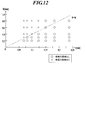
- 5 is a graph showing whether or not a suction hole pattern is generated, with the horizontal axis representing the thickness t of the recording medium and the vertical axis representing the diameter D of the maximum circle that fits within the opening at the opening end of the suction hole contacting the recording medium.
- 5 is a graph showing whether or not a suction hole pattern is generated, with the horizontal axis representing the thickness t of the recording medium and the vertical axis representing the diameter D of the maximum circle that fits within the opening at the opening end of the suction hole contacting the recording medium.
- FIG. 3 is a partial cross-sectional view of a recording medium, a recording medium holding layer, and a support layer, schematically showing air flow paths during suction with arrows.
- the ink jet recording apparatus 1 uses a temperature-sensitive and thick ink that changes in phase from gel or solid to liquid according to temperature.
- an ink jet recording apparatus 1 according to this embodiment includes a recording medium fixing means 2 for adsorbing and fixing a recording medium M, a suction pump 3 as a negative pressure generating means, an ink jet recording head 41, and a light irradiation means.
- a paper feed tray 51 for storing the recording medium M for storing the recording medium M
- a moving device 53 for the recording medium fixing means 2 for the recording medium fixing means 2
- a recording medium A transport device 54 that transports the recording medium M from the fixing means 2 to the paper discharge tray 55, a suction operation of the paper discharge tray 55 and the suction pump 3, a recording operation of the ink jet recording head 41, lighting of the light irradiation means 42, a transport device 52 and 54 and a control device (not shown) for controlling the entire apparatus including the transfer operation of the moving device 53.
- FIG. 2 shows a schematic diagram of the recording medium M, the recording medium fixing means 2, the suction pump 3, and the piping 31 connecting them.
- the recording medium M, the recording medium fixing means 2 and the pipe 31 are shown in cross section.
- the recording medium fixing means 2 supports the recording medium holding layer 6 and the recording medium holding layer 6 in which the suction holes 61 are formed and the ink is held at a temperature at which the ink becomes gel or solid.
- As the recording medium holding layer 6, a thin plate having a suction hole 61 perforated is mainly used.
- the support layer 7 has a structure having an internal space 72, and the support layer 7 is formed with suction holes 71 that communicate with the suction holes 61 from the internal space 72.
- the internal space 72 is connected to the suction pump 3 via the pipe 31.
- the recording medium M is sucked through the pipe 31, the internal space 72, and further the suction hole 71 and the suction hole 61, and the recording medium M is sucked into the suction hole on the surface of the recording medium holding layer 6.
- the temperature of the ink in the inkjet recording head 41 is adjusted so as to maintain a liquid state. Further, heating means for heating the recording medium fixing means 2 to a predetermined temperature is provided. This is to change the temperature of the ink that has landed on the recording medium M on the recording medium fixing means 2 to a gel or solid state.
- a heater such as a heating wire arranged in contact with the recording medium fixing means 2 or an infrared lamp for heating in a non-contact manner is used.
- an image is formed by ejecting liquid ink from the inkjet recording head 41 to the recording medium M adsorbed and fixed on the recording medium holding layer 6.
- the ink ejected from the ink jet recording head 41 is landed on the recording medium M, and becomes gelled or solidified and fixed on the recording medium M by lowering the temperature from the temperature at the time of ejection.
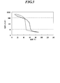
- An example of the temperature-viscosity characteristics of the gelled ink that gels at this time is shown in FIG.
- This gelled ink has a viscosity of 10 [mPa seconds] or less at an ink temperature of 80 ° C. or higher, but once it drops to a room temperature level (20 to 30 ° C.), the viscosity becomes several thousand [mPa seconds].
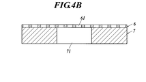
- the recording medium holding layer 6 in which a number of minute suction holes 61 are formed from the suction holes 71 of the support layer 7 contributes to the effect of preventing the pattern of the suction holes from appearing in the image.
- one suction hole 61 formed in the recording medium holding layer 6 has an opening area (upper end in FIG. 4B) in contact with the recording medium M, and the recording medium holding of one suction hole 71. The opening area is smaller than the opening area in contact with the layer 6.
- a large number of such minute suction holes 61 are formed in the recording medium holding layer 6 at substantially equal intervals.
- a region overlapping the suction hole 71 and a peripheral region of the suction hole 71 are included. Distributed.
- a large number of suction holes 71 are also distributed in the vertical and horizontal directions, and the structure shown in FIG.
- a member that forms the suction hole 61 and a member that forms the suction hole 71 may be overlapped, or a portion that becomes the recording medium holding layer 6 and the support layer 7 from before the suction hole 61 and the suction hole 71 are processed. Is formed by forming a relatively small hole as the suction hole 61 on one surface in contact with the recording medium M and forming a large hole as the suction hole 71 from the opposite surface. Good.
- the adsorption force on the surface on which the recording medium M in which the adsorption hole 61 is opened can be expressed by (total opening area) ⁇ (adsorption pressure).
- the suction force can be increased by increasing the ratio of the area occupied by the suction holes 61 in the region covered with the recording medium M, that is, the aperture ratio.
- increasing the area of each suction hole 61 makes it easier for the pattern of the suction hole to appear in the image, so that it is possible to increase the suction force while preventing the pattern of the suction hole from appearing in the image. It is necessary to form a larger number of fine suction holes and arrange them at high density.
- the recording medium holding layer 6 and the support layer 7 are separated, the following advantages are obtained. For example, it is highly difficult to form a large number of micro holes of less than ⁇ 1.0 mm, specifically ⁇ 0.4 mm, on an aluminum plate having a thickness of 5 mm. Since the adsorption force is determined by the aperture ratio and the adsorption pressure, it is necessary to increase the number of holes as the hole diameter is smaller in order to ensure an appropriate aperture ratio. When drilling micro holes in the support layer 7 having a thickness of about 5 mm, the micro holes must be drilled one by one, and a burr treatment is required for each hole. It will take.
- the recording medium holding layer 6 is made of a thin plate, specifically, a stainless steel having a thickness of 0.1 mm, it is possible to make a large number of ⁇ 0.4 mm or even smaller holes by etching at the same time, and no burr treatment is required. Can be manufactured at cost.
- the support layer 7 in which the suction hole 71 of ⁇ 1.0 mm is opened in 5 mm thick aluminum Furthermore, an OK top coat with a thickness of 0.056 mm (basis weight 73.3 gsm) is applied to the recording medium fixing means in which the recording medium holding layer 6 having a ⁇ 1.0 mm suction hole 62 is provided on 0.1 mm thick stainless steel.
- the graph of FIG. 6 shows the temperature change of the ink surface when an image is formed by ink jetting with + (Oji Paper) adsorbed as a recording medium.
- FIG. 6 shows the change in the ink surface temperature (contact portion, solid line graph) located at a position sufficiently away from the ⁇ 1.0 hole, in this example, 2 mm away.
- the recording medium M and the recording medium fixing means are heated to 45 ° C. in order to obtain a suitable gloss.
- the temperature difference between the hole (dashed line) and the contact (solid line) reaches 4.0 ° C. at the maximum.
- the difference in ink temperature decrease history between the hole and the contact portion is that there is no suction hole 62 below the recording medium M in the contact portion, and a member such as a metal having good thermal conductivity around the suction hole 62.
- a member such as a metal having good thermal conductivity around the suction hole 62.
- the ink temperature is difficult to escape because air is below the recording medium M in the hole.
- the difference in thermal conductivity between the hole (that is, air) and the contact portion (that is, metal) is 640 times even in the case of SUS304, which is sufficiently large.
- the recording medium holding layer 6 is made of stainless steel, carbon steel, or aluminum, the difference in ink temperature drop between the hole and the contact portion is the same.
- the support layer 7 having a suction hole 71 of ⁇ 1.0 mm in aluminum having a thickness of 5 mm is adsorbed by ⁇ 0.4 mm to a stainless steel having a thickness of 0.1 mm.
- an OK top coat + (Oji Paper) having a thickness of 0.056 mm (basis weight 73.3 gsm) is adsorbed as the recording medium.
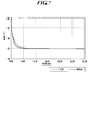
- FIG. 7 is a graph showing temperature changes on the ink surface when an image is formed by inkjet. Other conditions are the same as in the graph of FIG. As shown in the graph of FIG.
- the maximum temperature difference between the hole and the contact portion is 1.4 ° C., and it can be seen that the temperature difference between the hole and the contact portion is smaller than that in the graph of FIG.
- the difference between the graphs in FIGS. 6 and 7 is due to the difference in the suction hole diameter of the recording medium holding layer 6.
- the suction hole diameter of the recording medium holding layer 6 is ⁇ 1.0 mm, the pattern of the suction hole appears in the formed image, but when the suction hole diameter of the recording medium holding layer 6 is ⁇ 0.4 mm, it is formed. There is no suction hole pattern in the image.
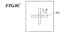
- the opening shape of the suction hole formed in the recording medium holding layer 6 is not limited to the circle shown in FIG.
- the shape may be a square, hexagon, cross, or the like. However, it is preferable to satisfy the following conditions.
- the diameter D is defined with reference to FIG. Since the suction hole 61a shown in FIG. 8A has a circular shape, the diameter D of the circle with the largest area that can be accommodated in the opening is equal to the diameter of the suction hole 61a.
- the suction hole is not circular, for example, in the suction hole 61b shown in FIG. 8B and the suction hole 61c shown in FIG.
- the circle indicated by the alternate long and short dash line is the maximum circle that can be accommodated inside the opening.
- the diameter of the circle is defined as D.
- the opening shape of the suction hole is preferably a shape in which the corner portion is rounded because stress concentrates on the corner portion if there is a corner shape.
- the cross-sectional shape of the suction hole is not limited to a columnar shape.
- the cross-sectional shape is a straight hole shape with a constant diameter like the suction hole 61a shown in FIG. 9A, or a tapered shape like the suction hole 61d shown in FIG. 9B.
- Various shapes such as a shape that expands at both ends, such as the suction hole 61e shown, can be adopted. In the case of the suction holes 61d and 61e, it is the diameter D of the maximum circle that fits in the opening at the opening end that contacts the recording medium.
- the suction hole 71 of the support layer 7 is not limited to the one having only the straight hole shown in FIG. 4, and the suction hole 71b in contact with the lower hole 71a and the recording medium holding layer 6 as shown in FIG.
- the structure which consists of can also be taken.
- the opening area of the suction hole 71 provided in the support layer 7 is the surface of the support layer 7 in contact with the recording medium holding layer 6. It refers to the opening area of the suction groove 71b that opens.
- FIGS. 11 and 12 show the suction hole pattern when the recording medium holding layer 6 is made of stainless steel having a thickness of 0.1 mm, and the suction holes 61 are arranged at a pitch of 1.5D and a 60 ° staggered arrangement (aperture ratio 40.3%). It is an evaluation result of the presence or absence of occurrence.
- OK top coat + (Oji Paper) was used as the recording medium M.
- npi fine quality (Nippon Paper Industries) was used as the recording medium M.
- the generation of the suction hole pattern can be prevented when the diameter D satisfies the relationship of D ⁇ 4t. . This is to reduce the temperature unevenness that occurs in the ink between the hole and the contact portion by reducing the distance from the hole on the center of the suction hole 61 of the recording medium M to the contact portion with the recording medium holding layer 6.
- the thinner the recording medium the smaller the distance between the recording medium holding layer 6 and the ink on the recording medium M, and the more likely the temperature unevenness occurs. Therefore, the thinner the recording medium, the smaller the diameter D needs to be.
- the thicker the recording medium M the greater the distance between the recording medium holding layer 6 and the ink on the recording medium M and the greater the heat insulation effect of the recording medium M, so that the ink temperature unevenness is reduced.
- the present invention can be effectively applied to an ink jet recording apparatus in which the thickness of the recording medium M is 0.15 mm or less.
- the opening ratio of the suction holes 61 can be set by the suction hole diameter, hole shape, hole pitch, and hole arrangement. It is preferable to determine the opening ratio represented by the opening area of the suction holes 61 occupying the surface area of the recording medium holding layer 6 in contact with the recording medium M within a range of 5% to 75%. If the aperture ratio is less than 5%, the recording medium cannot be adsorbed with a sufficient adsorbing force. If the aperture ratio exceeds 75%, the adsorbing force can be secured, but the recording medium holding layer is deformed due to insufficient rigidity. This is because there is a concern that temperature unevenness between the hole portion and the contact portion may not be sufficiently reduced because the contact portion is less than 25% and becomes local. More preferably, the aperture ratio is 10% or more and 50% or less.
- the arrangement of the suction holes 61 is not particularly limited, but a 60 ° staggered arrangement is preferable in order to arrange a large number of suction holes 61 at a high density.
- the adsorptive power was measured as follows. Thickness in which holes of ⁇ 1.0 mm are opened in a 60 ° staggered arrangement with a pitch of 6 mm as suction holes 71 and holes of ⁇ 0.2 mm are opened in a 60 ° staggered arrangement with a pitch of 0.3 mm as suction holes 71.
- a stainless steel recording medium holding layer 6 having a thickness of 0.1 mm was placed, and when a 100 mm ⁇ 297 mm size paper as the recording medium M was adsorbed at a negative pressure of 50 kPa, the paper peeling force was measured with a pull gauge. The measurement result of the peeling force was 180N.
- the peeling force was measured to be 112 N.
- the aperture ratio with respect to the recording medium decreases.
- the suction force increases when the recording medium holding layer 6 is inserted.
- the suction hole 61 that does not overlap the suction hole 71 of the support layer 7 also exerts an action of adsorbing the recording medium M due to an air leak between the recording medium holding layer 6 and the support layer 7. It is thought that it was because.
- the recording medium holding layer 6 is not integrated with the support layer 7, and the recording medium holding layer 6 is laminated on the support layer 7 between these layers. In order to obtain a high adsorption force, it is effective that the air leakage is enabled by the suction by the suction pump 3.
- the suction holes 61 As a method of forming the suction holes 61, since it is required to make a large number of small suction holes 61, it is preferable to manufacture them by etching or laser processing in consideration of productivity. In the case of etching processing, since it is basically impossible to make a hole with a pattern smaller than the plate thickness, it is necessary to make the plate thickness smaller than the suction hole diameter. Since the suction hole diameter of the recording medium holding layer 6 is preferably 0.4 mm or less, the plate thickness is preferably 0.4 mm or less. In the case of laser processing, when the plate thickness increases, drilling becomes difficult, and even when the hole is drilled, the taper becomes tight and the aperture ratio of the suction hole 61 cannot be increased.
- the thickness of the recording medium holding layer 6 needs to be 0.05 mm or more.
- the rigidity may be insufficient even if the opening ratio of the suction holes 61 is low.
- the heat capacity of the recording medium holding layer 6 is insufficient, and the temperature change of the recording medium holding layer 6 during ink jet recording becomes large, resulting in a temperature difference between the hole and the contact portion. There is a concern that it may expand and cause a suction hole pattern.
- the ratio of the heat capacity per unit area between the recording medium and the recording medium holding layer is preferably about 1: 4 to 1:10.
- the heat capacity per unit area is 1862 [J / (m 2 ⁇ K)] at a thickness of 0.4 mm, and the heat capacity per unit area is 204 [J / (m) at a thickness of 0.05 mm. 2 ⁇ K)].
- the heat capacity per unit area is 102 [J / (m 2 ⁇ K)].
- the material of the recording medium holding layer 6 is preferably stainless steel from the viewpoint of ensuring the rigidity of the recording medium holding layer 6 while realizing an appropriate suction hole shape and aperture ratio.
- the suction hole shape, the hole area ratio, and the thickness are set in consideration of the flexibility and rigidity of the material used and the fatigue limit.
- Aluminum A5052 has a tensile strength of 230 [N / mm 2 ]
- stainless steel SUS304 has a tensile strength of 520 [N / mm 2 ]. Since the recording medium holding layer 6 repeatedly adsorbs and discharges the recording medium M, it is necessary to pay attention to a decrease in mechanical strength due to repeated stress.
- Stainless steel has a fatigue limit for repeated stress, but aluminum does not have a clear fatigue limit. If the number of repeated stresses is increased, the breaking stress decreases. Therefore, from this point of view, the recording medium holding layer 6 is made of stainless steel. Is preferred.
- the present invention is not limited to the case where the recording medium holding layer 6 and the support layer 7 are flat, and the effect can be obtained even if the recording medium holding layer 6 and the support layer 7 are curved.
- the effect of the present invention can also be obtained by applying a drum for holding and transporting a recording medium and forming the peripheral surface of the drum with the recording medium holding layer 6 to carry out the present invention.
- an actinic ray curable ink that cures when irradiated with energy rays can be suitably applied.
- This actinic ray curable ink contains 1% by mass or more and less than 10% by mass of a gelling agent, and is characterized by reversible sol-gel phase transition depending on temperature.
- the sol-gel phase transition is a solution state with fluidity at high temperatures, but when cooled below the gelation temperature, the entire liquid gels and changes to a state in which it loses fluidity, and conversely loses fluidity at low temperatures. This refers to a phenomenon that returns to a fluid state with fluidity when heated to a temperature equal to or higher than the solation temperature.
- gelation is an interaction such as a lamellar structure, a polymer network formed by non-covalent bonds or hydrogen bonds, a polymer network formed by a physical aggregation state, and an aggregate structure of fine particles.
- solification refers to a state in which the interaction formed by the gelation is eliminated and the liquid state is changed to a fluid state.
- the solation temperature is a temperature at which fluidity develops when the gelled ink is heated, and the gelation temperature is when the ink in the sol state is cooled.
- the sol-gel phase transition actinic ray curable ink is in a liquid state at a high temperature, it can be ejected by an ink jet recording head.
- the ink is quickly cooled by natural cooling due to the temperature difference, and as a result, adjacent dots are coalesced. Can prevent image quality deterioration.
- the solidification force of the ink droplet is strong, the dots are isolated, resulting in unevenness in the image area, which may lead to an uneven glossiness such as an extremely low glossiness or an unnatural sparkle.
- an ink containing 0.1% by mass or more and less than 10% by mass of a gelling agent uses an ink having a viscosity at 25 ° C.
- the temperature control range of the medium corresponds to 42 to 48 ° C.
- the said base material temperature range is used by using the ink in which the viscosity in 25 degreeC of the ink containing 0.1 mass% or more and less than 10 mass% of gelling agents is 10 ⁇ 2 > mPa * s or more and less than 10 ⁇ 5 > mPa * s.
- Viscosity control is possible, and both image quality and natural gloss can be achieved. The reason is presumed as follows. With an ink having a viscosity at 25 ° C. of less than 10 2 mPa ⁇ s, the viscosity is insufficient to prevent liquid coalescence, and the image quality deteriorates in the above temperature range. In addition, with an ink having a viscosity at 25 ° C.
- the viscosity after gelation is high, and the viscosity tends to increase greatly during the cooling process, and the viscosity is controlled to an appropriate level in the above temperature range. This makes it difficult to achieve gloss reduction.
- it becomes a viscous gel with an appropriate viscosity after gelation it is possible to suppress the solidification force of dots more appropriately, and as a result, it is thought that an image with more natural gloss can be obtained. Yes.
- the gloss homogeneity does not mean an absolute gloss value, for example, a 60-degree specular gloss value, but an unnatural glitter or unnecessary gloss caused by a microscopic gloss difference on the image.
- actinic ray curable ink the difference between the ink gel temperature (Tgel) and the surface temperature (Ts) of the recording medium is adjusted to 5 to 15 ° C. An image with excellent sharpness and natural glossiness can be formed, but a better image can be formed by adjusting the temperature of the recording medium in the range of 5 to 10 ° C. It becomes.
- Gelation refers to interactions such as lamellar structures, polymer networks formed by non-covalent bonds and hydrogen bonds, polymer networks formed by physical aggregation, and aggregated structures of fine particles. It refers to a structure in which substances lose their independent movement due to action or the like, and indicate a solidified, semi-solidified, or thickened state with a sudden increase in viscosity or elasticity.
- a gel becomes a fluid solution (sometimes called a sol) by heating, and a thermoreversible gel that returns to the original gel when cooled. There is a heat irreversible gel that does not return.
- the gel formed by the oil gelling agent is preferably a thermoreversible gel from the viewpoint of preventing clogging in the head.
- the gelation temperature (phase transition temperature) of the ink is preferably 40 ° C. or higher and lower than 100 ° C., more preferably 45 ° C. or higher and 70 ° C. or lower.
- the phase transition temperature of the ink is 40 ° C. or higher, stable ejection characteristics can be obtained without being affected by the printing environment temperature when ejecting ink droplets from the recording head. If the temperature is less than 90 ° C., it is not necessary to heat the inkjet recording apparatus to an excessively high temperature, and the load on the head of the inkjet recording apparatus and the members of the ink supply system can be reduced.
- the gelation temperature refers to the temperature at which the viscosity suddenly changes from a fluid solution state to a gel state.
- Gel transition temperature, gel dissolution temperature, phase transition temperature, sol-gel phase transition temperature, gel It is synonymous with a term called a conversion point.
- the method for measuring the gelation temperature of the ink is, for example, using various rheometers (for example, a stress control type rheometer using a cone plate, Physica MCR series, manufactured by Anton Paar), and hot ink in a sol state at a low shear rate. It can be determined from a viscosity curve obtained while changing the temperature and a viscoelastic curve obtained by measuring the temperature change of dynamic viscoelasticity.
- a method in which a small iron piece sealed in a glass tube is placed in a dilatometer and a phase transition point is defined as a point at which the ink liquid does not naturally fall in response to a temperature change J. Polym. Sci., 21, 57 (1956)
- a method of measuring the temperature at which an aluminum cylinder naturally falls when an aluminum cylinder is placed on the ink and changing the gel temperature as a gelation temperature Journal of Japanese Society of Rheology, Vol. 17, 86 ( 1989)
- a gel-like test piece is placed on a heat plate, the heat plate is heated, the temperature at which the shape of the test piece collapses is measured, and this can be obtained as the gelation temperature.
- the gelation temperature (phase transition temperature) of the ink can be adjusted by changing the type of gelling agent used, the amount of gelling agent added, and the type of actinic ray curable monomer.
- the viscosity at 25 ° C. of the ink is preferably 10 2 mPa ⁇ s or more and less than 10 5 mPa ⁇ s, more preferably 10 3 mPa ⁇ s or more and less than 10 4 mPa ⁇ s. is there. If the ink viscosity is 10 2 mPa ⁇ s or more, deterioration of image quality due to dot coalescence can be prevented, and if it is less than 10 5 mPa ⁇ s, by controlling the surface temperature of the recording medium upon ink landing, A uniform gloss can be obtained by appropriate leveling.
- the viscosity of the ink can be appropriately adjusted by changing the type of gelling agent used, the amount of gelling agent added, and the type of actinic ray curable monomer.
- the ink viscosity was measured at a shear rate of 11.7 s ⁇ 1 using a stress-controlled rheometer using a cone plate, Physica MCR series, manufactured by Anton Paar).
- the gelling agent used in the ink may be a high molecular compound or a low molecular compound, but a low molecular compound is preferable from the viewpoint of ink jetting properties.
- the gelling agent that can be used in the ink according to the present invention are shown below, but the present invention is not limited only to these compounds.
- Specific examples of the polymer compound preferably used in the present invention include fatty acid inulins such as inulin stearate, fatty acid dextrins such as dextrin palmitate and dextrin myristate (available from Chiba Flour as the Leopard series), eicosane behenate Examples include glyceryl diacid, eicosane behenate polyglyceryl (available from Nisshin Oilio as Nomcoat series), and the like.
- low molecular weight compound preferably used in the present invention include, for example, low molecular weight oil gelling agents described in JP-A-2005-126507, JP-A-2005-255821 and JP-A-2010-1111790, N -Lauroyl-L-glutamic acid dibutylamide, N-2 ethylhexanoyl-L-glutamic acid dibutylamide and other amide compounds (available from Ajinomoto Finetechno), 1,3: 2,4-bis-O-benzylidene-D -Dibenzylidene sorbitols such as Glucitol (available from Gelol D Shin Nippon Rika), petroleum waxes such as paraffin wax, microcrystalline wax, petrolactam, candelilla wax, carnauba wax, rice wax, wood wax, Jojoba oil, jojoba solid wax, ho Plant waxes such as hover esters, animal waxes such as beeswax, lanolin and whale
- the ink contains a gelling agent, the ink immediately enters the gel state after being ejected from the ink jet recording head, and the mixing of dots and the coalescence of dots are suppressed.
- Image quality can be formed, and then cured by irradiation with actinic rays to be fixed on the recording medium to form a strong image film.
- content of a gelatinizer 1 mass% or more and less than 10 mass% are preferable, and 2 mass% or more and less than 7 mass% are more preferable.
- the actinic ray curable ink contains an actinic ray curable composition that cures with actinic rays together with a gelling agent and a coloring material.
- This actinic ray curable composition (hereinafter also referred to as a photopolymerizable compound) will be described.
- actinic rays include electron beams, ultraviolet rays, ⁇ rays, ⁇ rays, and X-rays.
- An electron beam is preferred. In the present invention, ultraviolet rays are particularly preferable.
- the photopolymerizable compound that is crosslinked or polymerized by irradiation with actinic rays can be used without particular limitation, but among them, a photocationic polymerizable compound or a photoradical polymerizable compound is preferably used.
- Photo cationic polymerizable compound As the photo cationic polymerizable monomer, various known cationic polymerizable monomers can be used. For example, JP-A-6-9714, JP-A-2001-31892, JP-A-2001-40068, JP-A-2001-55507, JP-A-2001-310938, JP-A-2001-310937, JP-A-2001-220526 Epoxy compounds, vinyl ether compounds, oxetane compounds and the like exemplified in each of the above publications.
- the present invention for the purpose of suppressing shrinkage of the recording medium during ink curing, it contains at least one oxetane compound as a photopolymerizable compound and at least one compound selected from an epoxy compound and a vinyl ether compound. Is preferred.
- a preferable aromatic epoxide is a di- or polyglycidyl ether produced by the reaction of a polyhydric phenol having at least one aromatic nucleus or an alkylene oxide adduct thereof and epichlorohydrin, such as bisphenol A or an alkylene oxide thereof.
- examples thereof include di- or polyglycidyl ethers of adducts, di- or polyglycidyl ethers of hydrogenated bisphenol A or its alkylene oxide adducts, and novolak-type epoxy resins.
- examples of the alkylene oxide include ethylene oxide and propylene oxide.
- cyclohexene oxide or cyclopentene obtained by epoxidizing a compound having at least one cycloalkane ring such as cyclohexene or cyclopentene ring with an appropriate oxidizing agent such as hydrogen peroxide or peracid.
- Oxide-containing compounds are preferred.
- Preferred examples of the aliphatic epoxides include di- or polyglycidyl ethers of aliphatic polyhydric alcohols or alkylene oxide adducts thereof, and typical examples thereof include diglycidyl ether of ethylene glycol, diglycidyl ether of propylene glycol or Diglycidyl ether of alkylene glycol such as diglycidyl ether of 1,6-hexanediol, polyglycidyl ether of polyhydric alcohol such as di- or triglycidyl ether of glycerin or its alkylene oxide adduct, polyethylene glycol or its alkylene oxide adduct Of polyalkylene glycols such as diglycidyl ether, polypropylene glycol or diglycidyl ether of its alkylene oxide adduct Glycidyl ether, and the like.
- examples of the alkylene oxide include ethylene oxide and propylene oxide.
- these epoxides in view of fast curability, aromatic epoxides and alicyclic epoxides are preferable, and alicyclic epoxides are particularly preferable.
- one of the above epoxides may be used alone, or two or more may be used in appropriate combination.
- vinyl ether compound examples include ethylene glycol divinyl ether, diethylene glycol divinyl ether, triethylene glycol divinyl ether, propylene glycol divinyl ether, dipropylene glycol divinyl ether, butanediol divinyl ether, hexanediol divinyl ether, cyclohexanedimethanol divinyl ether, Di- or trivinyl ether compounds such as methylolpropane trivinyl ether, ethyl vinyl ether, n-butyl vinyl ether, isobutyl vinyl ether, octadecyl vinyl ether, cyclohexyl vinyl ether, hydroxybutyl vinyl ether, 2-ethylhexyl vinyl ether, cyclohexane dimethanol monovinyl ether, n-propyl Pills vinyl ether, isopropyl vinyl ether, isopropenyl ether -o- propy
- vinyl ether compounds in consideration of curability, adhesion, and surface hardness, di- or trivinyl ether compounds are preferable, and divinyl ether compounds are particularly preferable.
- one of the above vinyl ether compounds may be used alone, or two or more thereof may be used in appropriate combination.
- the oxetane compound referred to in the present invention is a compound having an oxetane ring, and any known oxetane compound as described in JP-A Nos. 2001-220526 and 2001-310937 can be used.
- the viscosity of the ink composition becomes high, which makes handling difficult, and the glass transition temperature of the ink composition is high. Therefore, the tackiness of the obtained cured product may not be sufficient.
- the compound having an oxetane ring used in the present invention is preferably a compound having 1 to 4 oxetane rings.
- Examples of the compound having an oxetane ring that can be preferably used in the present invention include compounds represented by general formula (1) described in paragraph No. (0089) of JP-A No. 2005-255821 and the same publication.
- the general formula (2), the general formula (7) of the paragraph number (0107), the general formula (8) of the paragraph number (0109), and the general formula of the paragraph number (0166) described in the paragraph number (0092) of The compound represented by (9) etc. can be mentioned.
- Specific examples thereof include the exemplified compounds 1 to 6 described in paragraph numbers (0104) to (0119) and the compounds described in paragraph number (0121) of the publication.
- radically polymerizable monomers can be used as the photoradical polymerizable monomer.
- photocurable materials using photopolymerizable compositions described in JP-A-7-159983, JP-B-7-31399, JP-A-8-224982, and JP-A-10-863 and Cationic polymerization photocurable resins are known.
- photocationic polymerization photocurable resins sensitized to a long wavelength region longer than visible light are disclosed in, for example, JP-A-6-43633. It is disclosed in the Kaihei 8-324137 publication.
- the radical polymerizable compound is a compound having an ethylenically unsaturated bond capable of radical polymerization, and may be any compound as long as it has at least one ethylenically unsaturated bond capable of radical polymerization in the molecule. , Oligomers, polymers and the like having a chemical form. Only one kind of radically polymerizable compound may be used, or two or more kinds thereof may be used in combination at an arbitrary ratio in order to improve desired properties.
- Examples of compounds having an ethylenically unsaturated bond capable of radical polymerization include unsaturated carboxylic acids such as acrylic acid, methacrylic acid, itaconic acid, crotonic acid, isocrotonic acid, maleic acid and their salts, esters, urethanes, amides. And radically polymerizable compounds such as various anhydrides, acrylonitrile, styrene, various unsaturated polyesters, unsaturated polyethers, unsaturated polyamides, and unsaturated urethanes. Any known (meth) acrylate monomer and / or oligomer can be used as the radical polymerizable compound.
- the term “and / or” as used herein means that it may be a monomer or an oligomer, and may further include both. The same applies to the items described below.
- Examples of the compound having a (meth) acrylate group include isoamyl acrylate, stearyl acrylate, lauryl acrylate, octyl acrylate, decyl acrylate, isomyristyl acrylate, isostearyl acrylate, 2-ethylhexyl-diglycol acrylate, and 2-hydroxybutyl acrylate.
- 2-acryloyloxyethyl hexahydrophthalic acid butoxyethyl acrylate, ethoxydiethylene glycol acrylate, methoxydiethylene glycol acrylate, methoxypolyethylene glycol acrylate, methoxypropylene glycol acrylate, phenoxyethyl acrylate, tetrahydrofurfuryl acrylate, isobornyl acrylate, 2- Hydroxyethyl Aqua 2-hydroxypropyl acrylate, 2-hydroxy-3-phenoxypropyl acrylate, 2-acryloyloxyethyl succinic acid, 2-acryloyloxyethyl phthalic acid, 2-acryloyloxyethyl-2-hydroxyethyl-phthalic acid , Lactone-modified flexible acrylate, monofunctional monomer such as t-butylcyclohexyl acrylate, triethylene glycol diacrylate, tetraethylene glycol diacrylate, polyethylene glycol diacrylate,
- polymerizable oligomers can be blended in the same manner as the monomer.
- examples of the polymerizable oligomer include epoxy acrylate, aliphatic urethane acrylate, aromatic urethane acrylate, polyester acrylate, and linear acrylic oligomer.
- isoamyl acrylate, stearyl acrylate, lauryl acrylate, octyl acrylate, decyl acrylate, isomyristyl acrylate are particularly preferred from the viewpoints of sensitization, skin irritation, eye irritation, mutagenicity, toxicity, etc.
- stearyl acrylate lauryl acrylate, isostearyl acrylate, ethoxydiethylene glycol acrylate, isobornyl acrylate, tetraethylene glycol diacrylate, glycerin propoxy triacrylate, cowprolactone-modified trimethylolpropane triacrylate, caprolactam-modified dipenta Erythritol hexaacrylate is particularly preferred.
- a vinyl ether monomer and / or oligomer and a (meth) acrylate monomer and / or oligomer may be used in combination as the polymerizable compound.
- the vinyl ether monomer include ethylene glycol divinyl ether, diethylene glycol divinyl ether, triethylene glycol divinyl ether, propylene glycol divinyl ether, dipropylene glycol divinyl ether, butanediol divinyl ether, hexanediol divinyl ether, cyclohexanedimethanol divinyl ether, Di- or trivinyl ether compounds such as methylolpropane trivinyl ether, ethyl vinyl ether, n-butyl vinyl ether, isobutyl vinyl ether, octadecyl vinyl ether, cyclohexyl vinyl ether, hydroxybutyl vinyl ether, 2-ethylhexyl
- a bifunctional vinyl ether compound having a molecular weight of 300 to 1000 and having 2 to 3 ester groups in the molecule is preferable.
- compounds available as VEctomer series of ALDRICH, VEctomer 4010, VEctomer 4020, VEctomer 4040 , VEctomer 4060, VEctomer 5015 and the like are preferable, but not limited thereto.
- various vinyl ether compounds and maleimide compounds can be used in combination as the polymerizable compound.
- maleimide compounds include N-methylmaleimide, N-propylmaleimide, N-hexylmaleimide, N-laurylmaleimide, N-cyclohexylmaleimide, N-phenylmaleimide, N, N'-methylenebismaleimide, polypropylene glycol-bis (3-maleimidopropyl) ether, tetraethylene glycol-bis (3-maleimidopropyl) ether, bis (2-maleimidoethyl) carbonate, N, N '-(4,4'-diphenylmethane) bismaleimide, N, N' -2,4-tolylene bismaleimide or a polyfunctional maleimide compound which is an ester compound of maleimide carboxylic acid and various polyols disclosed in JP-A-11-124403.
- the addition amount of the cationic polymerizable compound and the radical polymerizable compound is preferably 1 to 97% by mass, more preferably 30 to 95%
- each component of ink As the color material constituting the ink, a dye or a pigment can be used without limitation, but it is preferable to use a pigment having good dispersion stability with respect to the ink component and excellent weather resistance. Although it does not necessarily limit as a pigment, For example, the organic or inorganic pigment of the following number described in a color index can be used for this invention. Examples of red or magenta pigments include Pigment Red 3, 5, 19, 22, 31, 38, 43, 48: 1, 48: 2, 48: 3, 48: 4, 48: 5, 49: 1, and 53: 1.
- Examples of green pigments include Pigment Green 7, 26, 36, 50, As the yellow pigment, Pigment Yellow 1, 3, 12, 13, 14, 17, 34, 35, 37, 55, 74, 81, 83, 93, 94, 95, 97, 108, 109, 110, 137, 138 139, 153, 154, 155, 157, 166, 167, 168, 180, 185, 193,
- Pigment Black 7, 28, 26 and the like can be used according to the purpose.
- Specific product names include, for example, chromo fine yellow 2080, 5900, 5930, AF-1300, 2700L, chromo fine orange 3700L, 6730, chromo fine scarlet 6750, chromo fine magenta 6880, 6886, 6891N, 6790, 6887.
- Chromofine Violet RE Chromofine Red 6820, 6830, Chromofine Blue HS-3, 5187, 5108, 5197, 5085N, SR-5020, 5026, 5050, 4920, 4927, 4937, 4824, 4933GN-EP, 4940, 4973, 5205, 5208, 5214, 5221, 5000P, Chromofine Green 2GN, 2GO, 2G-550D, 5310, 5370, 6830, Black Fine Black A-1103, Seika Fast Yellow 10GH, A-3, 2035, 2054, 2200, 2270, 2300, 2400 (B), 2500, 2600, ZAY-260, 2700 (B), 2770, Seika Fast Red 8040, C405 (F), CA120, LR-116, 1531B, 8060R, 1547, ZAW-262, 1537B, GY, 4R-4016, 3820, 3891, ZA-215, Seika Fast Carmine 6B1476T-7, 1483LT, 3840
- a ball mill, sand mill, attritor, roll mill, agitator, Henschel mixer, colloid mill, ultrasonic homogenizer, pearl mill, wet jet mill, paint shaker, or the like can be used.
- a dispersing agent can be added when dispersing the pigment.
- a polymer dispersant is preferably used. Examples of the polymer dispersant include Avecia's Solsperse series and Ajinomoto Fine-Techno's PB series. Furthermore, the following are mentioned.
- the pigment dispersant examples include a hydroxyl group-containing carboxylic acid ester, a salt of a long chain polyaminoamide and a high molecular weight acid ester, a salt of a high molecular weight polycarboxylic acid, a salt of a long chain polyaminoamide and a polar acid ester, a high molecular weight unsaturated acid ester, Polymer copolymer, modified polyurethane, modified polyacrylate, polyether ester type anionic activator, naphthalene sulfonic acid formalin condensate salt, aromatic sulfonic acid formalin condensate salt, polyoxyethylene alkyl phosphate ester, polyoxyethylene nonyl Examples thereof include phenyl ether, stearylamine acetate, and pigment derivatives.
- Anti-Terra-U polyaminoamide phosphate
- Anti-Terra-203 / 204 high molecular weight polycarboxylate
- Disbyk-101 polyaminoamide phosphate manufactured by BYK Chemie.
- Efka CHEMICALS “Efka 44, 46, 47, 48, 49, 54, 63, 64, 65, 66, 71, 701, 764, 766”, “Efka Polymer 100 (modified polyacrylate), 150 (aliphatic) System modified polymer), 400, 401, 402, 403, 450, 451, 452, 453 (modified polyacrylate), 745 (copper phthalocyanine system) ”;“ Floren TG-710 (urethane oligomer) ”manufactured by Kyoei Chemical Co., Ltd.,“ “Flonon SH-290, SP-1000”, “Polyflow No. 50E, No.
- pigment dispersants are preferably contained in the ink in the range of 0.1 to 20% by mass.
- a synergist according to various pigments as a dispersion aid.
- These dispersants and dispersion aids are preferably added in an amount of 1 to 50 parts by mass with respect to 100 parts by mass of the pigment.
- the dispersion medium is used using a solvent or a polymerizable compound.
- the ink is reacted and cured after printing, it is preferably solventless. If the solvent remains in the cured image, the solvent resistance deteriorates and the VOC of the remaining solvent arises.
- the dispersion medium is not a solvent but a polymerizable compound, and among them, a monomer having the lowest viscosity is selected.
- the pigment is preferably dispersed so that the average particle diameter of the pigment particles is 0.08 to 0.5 ⁇ m, and the maximum particle diameter is 0.3 to 10 ⁇ m, preferably 0.3 to 3 ⁇ m.
- the selection of the dispersion medium, the dispersion conditions, and the filtration conditions are appropriately set. By controlling the particle size, clogging of the nozzles of the recording head can be suppressed, and ink storage stability, ink transparency, and curing sensitivity can be maintained.
- oil-soluble dyes preferably oil-soluble dyes
- specific examples of oil-soluble dyes that can be used in the present invention are given below, but the present invention is not limited to these.
- Magnetic dye MS Magenta VP, MS Magenta HM-1450, MS Magenta HSo-147 (manufactured by Mitsui Toatsu Co., Ltd.), AIZENSOT Red-1, AIZEN SOT Red-2, AIZEN SOTRed-3, AIZEN SOT Pink-1, SPERON Red GE SPECIAL (above, manufactured by Hodogaya Chemical Co., Ltd.), RESOLIN Red FB 200%, MACROLEX Red Violet R, MACROLEX ROT5B (above, manufactured by Bayer Japan), KAYASET Red B, KAYASET Red 130, KAYASET Red Japan 802 ), PHLOXIN, ROSE BENGAL, ACID Red (above, made by Daiwa Kasei Co., Ltd.), HSR-31, DIARESIN Red K (below) , Manufactured by Mitsubishi Kasei Co., Ltd.), Oil Red (manufactured by BASF Japan Co., Ltd.).
- Blue GL-5 200 Light Blue BGL-5 200 (manufactured by Nippon Kayaku Co., Ltd.), DAIWA Blue 7000, Olesol Fast Blue GL (manufactured by Daiwa Kasei Co., Ltd.), DIARESIN Blue P (manufactured by Mitsubishi Kasei), SUDAN Blue 670, NEOPEN Blue 808, ZAPON Blue 806 (above, manufactured by BASF Japan).
- Black dye MS Black VPC (Mitsui Toatsu Co., Ltd.), AIZEN SOT Black-1, AIZEN SOT Black-5 (above, Hodogaya Chemical Co., Ltd.), RESORIN Black GSN 200%, RESOLIN Black BS (above, Bayer Japan, Inc.), KAYASET Black A-N (manufactured by Nippon Kayaku Co., Ltd.), DAIWA Black MSC (manufactured by Daiwa Kasei Co., Ltd.), HSB-202 (manufactured by Mitsubishi Kasei Co., Ltd.), NEPTUNE Black X60, NEOPEN Black X58 (manufactured by BASF Japan) .
- the amount of pigment or oil-soluble dye added is preferably 0.1 to 20% by mass, more preferably 0.4 to 10% by mass. If it is 0.1% by mass or more, good image quality can be obtained, and if it is 20% by mass or less, an appropriate ink viscosity in ink ejection can be obtained. In addition, two or more kinds of colorants can be mixed as appropriate for color adjustment.
- Photopolymerization initiator When ultraviolet rays or the like are used as the actinic rays, it is preferable to contain at least one photopolymerization initiator. However, in the case where an electron beam is used as the actinic ray, a photopolymerization initiator is not required in many cases.
- Photopolymerization initiators can be broadly classified into two types: intramolecular bond cleavage type and intramolecular hydrogen abstraction type. Examples of the intramolecular bond cleavage type photopolymerization initiator include diethoxyacetophenone, 2-hydroxy-2-methyl-1-phenylpropan-1-one, benzyldimethyl ketal, and 1- (4-isopropylphenyl) -2.
- examples of the intramolecular hydrogen abstraction type photopolymerization initiator include benzophenone, methyl 4-phenylbenzophenone, 4,4'-dichlorobenzophenone, hydroxybenzophenone, 4-benzoyl-4'-methyl, o-benzoylbenzoate.
- Benzophenones such as diphenyl sulfide, acrylated benzophenone, 3,3 ′, 4,4′-tetra (t-butylperoxycarbonyl) benzophenone, 3,3′-dimethyl-4-methoxybenzophenone; 2-isopropylthioxanthone, 2 Thioxanthone series such as 1,4-dimethylthioxanthone, 2,4-diethylthioxanthone, 2,4-dichlorothioxanthone; Michler-ketone, aminobenzophenone series such as 4,4'-diethylaminobenzophenone; 10-butyl- - chloro acridone, 2-ethyl anthraquinone, 9,10-phenanthrenequinone, camphorquinone, and the like.
- the blending amount is preferably in the range of 0.01 to 10% by mass of the actinic ray curable composition.
- the radical polymerization initiator include triazine derivatives described in JP-B-59-1281, JP-B-61-9621, JP-A-60-60104, JP-A-59-1504, and JP-A-59-1504.
- polymerization initiators are preferably contained in the range of 0.01 to 10 parts by mass with respect to 100 parts by mass of the compound having an ethylenically unsaturated bond capable of radical polymerization.
- a photoacid generator can also be used as a photopolymerization initiator.
- the photoacid generator for example, a chemically amplified photoresist or a compound used for photocationic polymerization is used (edited by Organic Electronics Materials Research Group, “Organic Materials for Imaging”, Bunshin Publishing (1993), 187. See page 192).
- Examples of compounds suitable for the present invention are listed below.
- B (C 6 F 5 ) 4 ⁇ , PF 6 ⁇ , AsF 6 ⁇ , SbF 6 ⁇ , and CF 3 SO 3 — salts of aromatic onium compounds such as diazonium, ammonium, iodonium, sulfonium, and phosphonium are listed. be able to.
- Specific examples of the onium compound that can be used in the present invention include compounds described in paragraph No.
- JP-A No. 2005-255821 Specific examples of the sulfonated compound that generates sulfonic acid include compounds described in paragraph No. (0136) of JP-A No. 2005-255821.
- halides that generate hydrogen halide can also be used, and specific examples thereof include compounds described in paragraph No. (0138) of JP-A No. 2005-255821. it can.
- an iron allene complex described in paragraph No. (0140) of JP-A-2005-255821 can be mentioned.
- additives can be used for the actinic ray curable ink.
- surfactants leveling additives, matting agents, polyester resins for adjusting film properties, polyurethane resins, vinyl resins, acrylic resins, rubber resins, and waxes
- any known basic compound can be used for the purpose of improving storage stability. Typical examples include basic organic compounds such as basic alkali metal compounds, basic alkaline earth metal compounds, and amines. Etc.
- the pigment dispersion used in the following ink composition contains 5 parts of Solspers 32000 (manufactured by Lubrizol) and 80 parts of HD-N (1,6-hexanediol dimethacrylate: Shin-Nakamura Chemical Co., Ltd.). After stirring and dissolving in a stainless steel beaker and cooling it to room temperature, add 15 parts of carbon black (# 56: manufactured by Mitsubishi Chemical Corporation), seal it in a glass bottle with 0.5 mm zirconia beads, and put it in a paint shaker. Then, after 10 hours of dispersion treatment, zirconia beads were removed.
- the ink jet recording apparatus may be used in the field of image formation using ink that changes phase according to temperature.
Abstract
Priority Applications (4)
| Application Number | Priority Date | Filing Date | Title |
|---|---|---|---|
| JP2013512386A JP5954317B2 (ja) | 2011-04-27 | 2012-04-25 | インクジェット記録装置 |
| EP12777114.5A EP2703173A4 (fr) | 2011-04-27 | 2012-04-25 | Dispositif d'impression à jet d'encre |
| CN201280019857.7A CN103502015B (zh) | 2011-04-27 | 2012-04-25 | 喷墨记录装置 |
| US14/113,621 US20140049590A1 (en) | 2011-04-27 | 2012-04-25 | Inkjet recording device |
Applications Claiming Priority (2)
| Application Number | Priority Date | Filing Date | Title |
|---|---|---|---|
| JP2011-099562 | 2011-04-27 | ||
| JP2011099562 | 2011-04-27 |
Publications (1)
| Publication Number | Publication Date |
|---|---|
| WO2012147760A1 true WO2012147760A1 (fr) | 2012-11-01 |
Family
ID=47072278
Family Applications (1)
| Application Number | Title | Priority Date | Filing Date |
|---|---|---|---|
| PCT/JP2012/061024 WO2012147760A1 (fr) | 2011-04-27 | 2012-04-25 | Dispositif d'impression à jet d'encre |
Country Status (5)
| Country | Link |
|---|---|
| US (1) | US20140049590A1 (fr) |
| EP (1) | EP2703173A4 (fr) |
| JP (1) | JP5954317B2 (fr) |
| CN (1) | CN103502015B (fr) |
| WO (1) | WO2012147760A1 (fr) |
Cited By (4)
| Publication number | Priority date | Publication date | Assignee | Title |
|---|---|---|---|---|
| WO2015015482A1 (fr) * | 2013-07-28 | 2015-02-05 | Hewlett-Packard Industrial Printing Ltd. | Porte-support |
| JP2018176496A (ja) * | 2017-04-07 | 2018-11-15 | セイコーエプソン株式会社 | 液体吐出装置 |
| US20220088949A1 (en) * | 2018-12-20 | 2022-03-24 | Kateeva, Inc. | Inkjet printer with temperature controlled substrate support |
| JP7457346B2 (ja) | 2019-11-27 | 2024-03-28 | アジア・ラゲージ株式会社 | インクジェット印刷装置 |
Families Citing this family (6)
| Publication number | Priority date | Publication date | Assignee | Title |
|---|---|---|---|---|
| EP2748005B1 (fr) * | 2011-08-22 | 2015-10-14 | Windmöller & Hölscher KG | Machine et procédé d'impression de bandes de matériau |
| US20140208970A1 (en) * | 2011-08-22 | 2014-07-31 | Windmoeller & Hoelscher Kg | Machine and method for printing material webs |
| JP6277624B2 (ja) * | 2013-08-05 | 2018-02-14 | セイコーエプソン株式会社 | 記録装置 |
| JP6672825B2 (ja) * | 2016-01-20 | 2020-03-25 | セイコーエプソン株式会社 | 印刷装置 |
| FR3051718A1 (fr) * | 2016-05-27 | 2017-12-01 | Mgi Digital Tech | Dispositif et procede de maintien/transport de substrats dans une machine d'impression |
| WO2023211452A1 (fr) * | 2022-04-28 | 2023-11-02 | Hewlett-Packard Development Company, L.P. | Impression sur un vêtement |
Citations (49)
| Publication number | Priority date | Publication date | Assignee | Title |
|---|---|---|---|---|
| US2848328A (en) | 1954-06-16 | 1958-08-19 | Eastman Kodak Co | Light sensitive diazo compound and binder composition |
| US2852379A (en) | 1955-05-04 | 1958-09-16 | Eastman Kodak Co | Azide resin photolithographic composition |
| US2940853A (en) | 1958-08-21 | 1960-06-14 | Eastman Kodak Co | Azide sensitized resin photographic resist |
| JPS3622062B1 (fr) | 1960-01-14 | 1961-11-15 | ||
| JPS3713109B1 (fr) | 1960-01-14 | 1962-09-06 | ||
| JPS3818015B1 (fr) | 1960-11-11 | 1963-09-12 | ||
| JPS4323684B1 (fr) | 1965-04-01 | 1968-10-12 | ||
| JPS446413B1 (fr) | 1965-06-28 | 1969-03-19 | ||
| JPS459610B1 (fr) | 1965-07-19 | 1970-04-07 | ||
| US3567453A (en) | 1967-12-26 | 1971-03-02 | Eastman Kodak Co | Light sensitive compositions for photoresists and lithography |
| JPS471604B1 (fr) | 1968-12-06 | 1972-01-17 | ||
| JPS5539162B2 (fr) | 1975-05-02 | 1980-10-08 | ||
| JPS591504A (ja) | 1982-06-26 | 1984-01-06 | Nippon Oil & Fats Co Ltd | 光重合開始剤組成物 |
| JPS591281B2 (ja) | 1971-09-03 | 1984-01-11 | ミネソタ マイニング アンド マニュファクチュアリング コンパニ− | ヒカリジユウゴウカイシザイ |
| JPS5914023A (ja) | 1982-07-15 | 1984-01-24 | Chugoku Denki Seizo Kk | フリツカ抑制装置の制御方式 |
| EP0109851A2 (fr) | 1982-11-22 | 1984-05-30 | Minnesota Mining And Manufacturing Company | Compositions polymérisables par apport d'énergie contenant des initiateurs organométalliques |
| JPS59107344A (ja) | 1982-12-13 | 1984-06-21 | Hitachi Chem Co Ltd | 感光性樹脂組成物 |
| JPS59142205A (ja) | 1983-02-02 | 1984-08-15 | Nippon Oil & Fats Co Ltd | 高感度光開始剤組成物 |
| EP0126712A1 (fr) | 1983-05-18 | 1984-11-28 | Ciba-Geigy Ag | Composition durcissable et son utilisation |
| JPS6060104A (ja) | 1983-09-12 | 1985-04-06 | Fuji Photo Film Co Ltd | 光重合性組成物 |
| JPS619621B2 (fr) | 1978-05-18 | 1986-03-25 | Fuji Photo Film Co Ltd | |
| JPS61151197A (ja) | 1984-12-20 | 1986-07-09 | チバ‐ガイギー アーゲー | チタノセン類およびこれらのチタノセン類を含有する照射重合開始剤 |
| JPS61243807A (ja) | 1985-04-23 | 1986-10-30 | Nippon Oil & Fats Co Ltd | 光重合開始剤 |
| JPS6454440A (en) | 1987-08-24 | 1989-03-01 | Toyo Boseki | Photopolymerizable composition |
| JPH02182701A (ja) | 1988-11-08 | 1990-07-17 | Mead Corp:The | 遷移金属配立錯体カチオンとボレートアニオンを含有した感光性組成物及びそれを使用した感光性材料 |
| JPH0371850A (ja) | 1989-08-11 | 1991-03-27 | Fuji Xerox Co Ltd | 印字記録方法 |
| JPH03209477A (ja) | 1989-10-13 | 1991-09-12 | Fuji Photo Film Co Ltd | アルミナート錯体からなる光重合開始剤及び光重合性組成物 |
| JPH069714A (ja) | 1992-06-29 | 1994-01-18 | Sumitomo Chem Co Ltd | 光重合性組成物及び光制御板の製造方法 |
| JPH0643633A (ja) | 1992-05-06 | 1994-02-18 | Kyowa Hakko Kogyo Co Ltd | 化学増幅型レジスト組成物 |
| JPH0731399B2 (ja) | 1984-12-21 | 1995-04-10 | 三菱化学株式会社 | 光重合性組成物 |
| JPH07159983A (ja) | 1993-12-03 | 1995-06-23 | Fuji Photo Film Co Ltd | 感光性印刷版 |
| JPH08224982A (ja) | 1995-02-22 | 1996-09-03 | Konica Corp | 転写箔及びそれを用いたidカード |
| JPH08324137A (ja) | 1996-07-01 | 1996-12-10 | Konica Corp | 画像記録体およびその製造方法 |
| JP2711491B2 (ja) | 1992-02-07 | 1998-02-10 | 東洋インキ製造株式会社 | スルホニウム錯体またはオキソスルホニウム錯体 |
| JP2803454B2 (ja) | 1992-03-13 | 1998-09-24 | 東洋インキ製造株式会社 | スルホニウム錯体またはオキソスルホニウム錯体 |
| JPH11124403A (ja) | 1997-05-16 | 1999-05-11 | Dainippon Ink & Chem Inc | マレイミド誘導体を含有する活性エネルギー線硬化性組成物及び該活性エネルギー線硬化性組成物の硬化方法 |
| JP2001031892A (ja) | 1999-07-23 | 2001-02-06 | Toyo Ink Mfg Co Ltd | 紫外線硬化型塗料組成物及びその利用 |
| JP2001040068A (ja) | 1999-07-27 | 2001-02-13 | Asahi Denka Kogyo Kk | 光重合性組成物 |
| JP2001055507A (ja) | 1999-08-19 | 2001-02-27 | Kansai Paint Co Ltd | 活性エネルギー線硬化性組成物およびその被膜形成方法 |
| JP2001220526A (ja) | 2000-02-09 | 2001-08-14 | Brother Ind Ltd | インクジェット記録方式用エネルギー線硬化型組成物 |
| JP2001310937A (ja) | 2000-04-27 | 2001-11-06 | Hitachi Chem Co Ltd | 硬化性オキセタン組成物およびその硬化方法ならびにその方法により得られる硬化物 |
| JP2001310938A (ja) | 2000-04-28 | 2001-11-06 | Showa Denko Kk | 重合性組成物、その硬化物と製造方法 |
| JP2003182168A (ja) * | 2001-12-25 | 2003-07-03 | Mutoh Ind Ltd | インクジェット記録装置 |
| JP2005126507A (ja) | 2003-10-22 | 2005-05-19 | Konica Minolta Holdings Inc | インクジェット用インク及びそれを用いたインクジェット記録方法 |
| JP2005255821A (ja) | 2004-03-11 | 2005-09-22 | Konica Minolta Holdings Inc | 活性光線硬化型インクジェットインクとそれを用いたインクジェット記録方法 |
| JP2010111790A (ja) | 2008-11-07 | 2010-05-20 | Konica Minolta Holdings Inc | 活性光線硬化型インクジェット用インクとそれを用いたインクジェット記録方法 |
| JP2010264624A (ja) * | 2009-05-13 | 2010-11-25 | Mimaki Engineering Co Ltd | 吸着装置及び吸着装置の製造方法 |
| JP2011020377A (ja) | 2009-07-16 | 2011-02-03 | Fujifilm Corp | インクジェット記録装置およびインクジェット記録方法 |
| JP2011032036A (ja) | 2009-07-31 | 2011-02-17 | Fujifilm Corp | 媒体固定装置及び画像形成装置 |
Family Cites Families (12)
| Publication number | Priority date | Publication date | Assignee | Title |
|---|---|---|---|---|
| US6315404B1 (en) * | 1999-12-21 | 2001-11-13 | Hewlett-Packard Company | Heated vacuum platen |
| US6497522B2 (en) * | 2000-04-17 | 2002-12-24 | Hewlett-Packard Company | Edge lift reduction for belt type transports |
| JP2002221616A (ja) * | 2000-11-21 | 2002-08-09 | Seiko Epson Corp | カラーフィルタの製造方法及び製造装置、液晶装置の製造方法及び製造装置、el装置の製造方法及び製造装置、インクジェットヘッドの制御装置、材料の吐出方法及び材料の吐出装置、並びに電子機器 |
| EP1958783B1 (fr) * | 2002-12-11 | 2010-04-07 | Konica Minolta Holdings, Inc. | Imprimante à jet d'encre et procédé d'enregistrement d'image |
| JP4849673B2 (ja) * | 2006-07-06 | 2012-01-11 | 株式会社ミマキエンジニアリング | 印刷装置、搬送装置、及び印刷方法 |
| JP4600483B2 (ja) * | 2008-01-28 | 2010-12-15 | セイコーエプソン株式会社 | 液滴吐出装置、吐出方法、カラーフィルタの製造方法、有機el装置の製造方法 |
| JP5239827B2 (ja) * | 2008-03-25 | 2013-07-17 | セイコーエプソン株式会社 | 記録装置 |
| JP5125678B2 (ja) * | 2008-03-27 | 2013-01-23 | セイコーエプソン株式会社 | 記録装置 |
| JP5482012B2 (ja) * | 2008-09-19 | 2014-04-23 | セイコーエプソン株式会社 | ターゲット支持装置、ターゲット搬送機構及び液体噴射装置 |
| CN102712198B (zh) * | 2010-01-13 | 2015-06-10 | 株式会社御牧工程 | 喷墨打印机及输送介质的方法 |
| JP5747463B2 (ja) * | 2010-08-20 | 2015-07-15 | セイコーエプソン株式会社 | 記録装置およびそのワーク除給材方法 |
| JP5708076B2 (ja) * | 2011-03-15 | 2015-04-30 | セイコーエプソン株式会社 | 記録装置 |
-
2012
- 2012-04-25 EP EP12777114.5A patent/EP2703173A4/fr not_active Ceased
- 2012-04-25 US US14/113,621 patent/US20140049590A1/en not_active Abandoned
- 2012-04-25 JP JP2013512386A patent/JP5954317B2/ja not_active Expired - Fee Related
- 2012-04-25 WO PCT/JP2012/061024 patent/WO2012147760A1/fr active Application Filing
- 2012-04-25 CN CN201280019857.7A patent/CN103502015B/zh active Active
Patent Citations (49)
| Publication number | Priority date | Publication date | Assignee | Title |
|---|---|---|---|---|
| US2848328A (en) | 1954-06-16 | 1958-08-19 | Eastman Kodak Co | Light sensitive diazo compound and binder composition |
| US2852379A (en) | 1955-05-04 | 1958-09-16 | Eastman Kodak Co | Azide resin photolithographic composition |
| US2940853A (en) | 1958-08-21 | 1960-06-14 | Eastman Kodak Co | Azide sensitized resin photographic resist |
| JPS3622062B1 (fr) | 1960-01-14 | 1961-11-15 | ||
| JPS3713109B1 (fr) | 1960-01-14 | 1962-09-06 | ||
| JPS3818015B1 (fr) | 1960-11-11 | 1963-09-12 | ||
| JPS4323684B1 (fr) | 1965-04-01 | 1968-10-12 | ||
| JPS446413B1 (fr) | 1965-06-28 | 1969-03-19 | ||
| JPS459610B1 (fr) | 1965-07-19 | 1970-04-07 | ||
| US3567453A (en) | 1967-12-26 | 1971-03-02 | Eastman Kodak Co | Light sensitive compositions for photoresists and lithography |
| JPS471604B1 (fr) | 1968-12-06 | 1972-01-17 | ||
| JPS591281B2 (ja) | 1971-09-03 | 1984-01-11 | ミネソタ マイニング アンド マニュファクチュアリング コンパニ− | ヒカリジユウゴウカイシザイ |
| JPS5539162B2 (fr) | 1975-05-02 | 1980-10-08 | ||
| JPS619621B2 (fr) | 1978-05-18 | 1986-03-25 | Fuji Photo Film Co Ltd | |
| JPS591504A (ja) | 1982-06-26 | 1984-01-06 | Nippon Oil & Fats Co Ltd | 光重合開始剤組成物 |
| JPS5914023A (ja) | 1982-07-15 | 1984-01-24 | Chugoku Denki Seizo Kk | フリツカ抑制装置の制御方式 |
| EP0109851A2 (fr) | 1982-11-22 | 1984-05-30 | Minnesota Mining And Manufacturing Company | Compositions polymérisables par apport d'énergie contenant des initiateurs organométalliques |
| JPS59107344A (ja) | 1982-12-13 | 1984-06-21 | Hitachi Chem Co Ltd | 感光性樹脂組成物 |
| JPS59142205A (ja) | 1983-02-02 | 1984-08-15 | Nippon Oil & Fats Co Ltd | 高感度光開始剤組成物 |
| EP0126712A1 (fr) | 1983-05-18 | 1984-11-28 | Ciba-Geigy Ag | Composition durcissable et son utilisation |
| JPS6060104A (ja) | 1983-09-12 | 1985-04-06 | Fuji Photo Film Co Ltd | 光重合性組成物 |
| JPS61151197A (ja) | 1984-12-20 | 1986-07-09 | チバ‐ガイギー アーゲー | チタノセン類およびこれらのチタノセン類を含有する照射重合開始剤 |
| JPH0731399B2 (ja) | 1984-12-21 | 1995-04-10 | 三菱化学株式会社 | 光重合性組成物 |
| JPS61243807A (ja) | 1985-04-23 | 1986-10-30 | Nippon Oil & Fats Co Ltd | 光重合開始剤 |
| JPS6454440A (en) | 1987-08-24 | 1989-03-01 | Toyo Boseki | Photopolymerizable composition |
| JPH02182701A (ja) | 1988-11-08 | 1990-07-17 | Mead Corp:The | 遷移金属配立錯体カチオンとボレートアニオンを含有した感光性組成物及びそれを使用した感光性材料 |
| JPH0371850A (ja) | 1989-08-11 | 1991-03-27 | Fuji Xerox Co Ltd | 印字記録方法 |
| JPH03209477A (ja) | 1989-10-13 | 1991-09-12 | Fuji Photo Film Co Ltd | アルミナート錯体からなる光重合開始剤及び光重合性組成物 |
| JP2711491B2 (ja) | 1992-02-07 | 1998-02-10 | 東洋インキ製造株式会社 | スルホニウム錯体またはオキソスルホニウム錯体 |
| JP2803454B2 (ja) | 1992-03-13 | 1998-09-24 | 東洋インキ製造株式会社 | スルホニウム錯体またはオキソスルホニウム錯体 |
| JPH0643633A (ja) | 1992-05-06 | 1994-02-18 | Kyowa Hakko Kogyo Co Ltd | 化学増幅型レジスト組成物 |
| JPH069714A (ja) | 1992-06-29 | 1994-01-18 | Sumitomo Chem Co Ltd | 光重合性組成物及び光制御板の製造方法 |
| JPH07159983A (ja) | 1993-12-03 | 1995-06-23 | Fuji Photo Film Co Ltd | 感光性印刷版 |
| JPH08224982A (ja) | 1995-02-22 | 1996-09-03 | Konica Corp | 転写箔及びそれを用いたidカード |
| JPH08324137A (ja) | 1996-07-01 | 1996-12-10 | Konica Corp | 画像記録体およびその製造方法 |
| JPH11124403A (ja) | 1997-05-16 | 1999-05-11 | Dainippon Ink & Chem Inc | マレイミド誘導体を含有する活性エネルギー線硬化性組成物及び該活性エネルギー線硬化性組成物の硬化方法 |
| JP2001031892A (ja) | 1999-07-23 | 2001-02-06 | Toyo Ink Mfg Co Ltd | 紫外線硬化型塗料組成物及びその利用 |
| JP2001040068A (ja) | 1999-07-27 | 2001-02-13 | Asahi Denka Kogyo Kk | 光重合性組成物 |
| JP2001055507A (ja) | 1999-08-19 | 2001-02-27 | Kansai Paint Co Ltd | 活性エネルギー線硬化性組成物およびその被膜形成方法 |
| JP2001220526A (ja) | 2000-02-09 | 2001-08-14 | Brother Ind Ltd | インクジェット記録方式用エネルギー線硬化型組成物 |
| JP2001310937A (ja) | 2000-04-27 | 2001-11-06 | Hitachi Chem Co Ltd | 硬化性オキセタン組成物およびその硬化方法ならびにその方法により得られる硬化物 |
| JP2001310938A (ja) | 2000-04-28 | 2001-11-06 | Showa Denko Kk | 重合性組成物、その硬化物と製造方法 |
| JP2003182168A (ja) * | 2001-12-25 | 2003-07-03 | Mutoh Ind Ltd | インクジェット記録装置 |
| JP2005126507A (ja) | 2003-10-22 | 2005-05-19 | Konica Minolta Holdings Inc | インクジェット用インク及びそれを用いたインクジェット記録方法 |
| JP2005255821A (ja) | 2004-03-11 | 2005-09-22 | Konica Minolta Holdings Inc | 活性光線硬化型インクジェットインクとそれを用いたインクジェット記録方法 |
| JP2010111790A (ja) | 2008-11-07 | 2010-05-20 | Konica Minolta Holdings Inc | 活性光線硬化型インクジェット用インクとそれを用いたインクジェット記録方法 |
| JP2010264624A (ja) * | 2009-05-13 | 2010-11-25 | Mimaki Engineering Co Ltd | 吸着装置及び吸着装置の製造方法 |
| JP2011020377A (ja) | 2009-07-16 | 2011-02-03 | Fujifilm Corp | インクジェット記録装置およびインクジェット記録方法 |
| JP2011032036A (ja) | 2009-07-31 | 2011-02-17 | Fujifilm Corp | 媒体固定装置及び画像形成装置 |
Non-Patent Citations (11)
| Title |
|---|
| "Kakyozai Handobukku", 1981, TAISEISHA |
| "Organic materials for imaging", 1993, BUNSHIN, pages: 187 - 192 |
| "UV-EB Koukagijyutsu no Ouyo to Shijyo", 1989, CMC PUBLISHING CO., LTD., pages: 79 |
| COORDINATION CHEMISTRY REVIEW, vol. 84, 1988, pages 85 - 277 |
| EIICHIRO TAKIYAMA: "Poriesuteru Jyushi Handbook", 1988, NIKKAN KOGYO SHIMBUN LTD. |
| J.IMAG.SCI., vol. 30, 1986, pages 174 |
| J.POLYM.SCI., vol. 21, 1956, pages 57 |
| KIYOMI KATO: "UV·EB Kouka Handobukku", vol. 185, KOUBUNSHI KANKOUKAI |
| MACROMOLECULES, vol. 10, 1977, pages 1307 |
| NIHON REOROJ I GAKKAISHI, vol. 17, 1989, pages 86 |
| See also references of EP2703173A4 |
Cited By (19)
| Publication number | Priority date | Publication date | Assignee | Title |
|---|---|---|---|---|
| CN105745081B (zh) * | 2013-07-28 | 2019-10-25 | 惠普工业印刷有限公司 | 介质支承装置 |
| US10549555B2 (en) | 2013-07-28 | 2020-02-04 | Hp Scitex Ltd. | Media support |
| US10252550B2 (en) | 2013-07-28 | 2019-04-09 | Hp Scitex Ltd. | Media support |
| CN105705338A (zh) * | 2013-07-28 | 2016-06-22 | 惠普工业印刷有限公司 | 介质支承装置 |
| CN105745081A (zh) * | 2013-07-28 | 2016-07-06 | 惠普工业印刷有限公司 | 介质支承装置 |
| CN105745080A (zh) * | 2013-07-28 | 2016-07-06 | 惠普工业印刷有限公司 | 介质支承装置 |
| US10022987B2 (en) | 2013-07-28 | 2018-07-17 | Hp Scitex Ltd. | Media support |
| US10105967B2 (en) | 2013-07-28 | 2018-10-23 | Hp Scitex Ltd. | Media support |
| WO2015015483A1 (fr) * | 2013-07-28 | 2015-02-05 | Hewlett-Packard Industrial Printing Ltd. | Porte-support |
| US10828916B2 (en) | 2013-07-28 | 2020-11-10 | Hp Scitex Ltd. | Media support |
| US10300715B2 (en) | 2013-07-28 | 2019-05-28 | Hp Scitex Ltd. | Media support |
| US10259237B2 (en) | 2013-07-28 | 2019-04-16 | Hp Scitex Ltd. | Media support |
| WO2015015482A1 (fr) * | 2013-07-28 | 2015-02-05 | Hewlett-Packard Industrial Printing Ltd. | Porte-support |
| WO2015015481A1 (fr) * | 2013-07-28 | 2015-02-05 | Hewlett-Packard Industrial Printing Ltd. | Support de média |
| JP2018176496A (ja) * | 2017-04-07 | 2018-11-15 | セイコーエプソン株式会社 | 液体吐出装置 |
| US20220088949A1 (en) * | 2018-12-20 | 2022-03-24 | Kateeva, Inc. | Inkjet printer with temperature controlled substrate support |
| US11660891B2 (en) * | 2018-12-20 | 2023-05-30 | Kateeva, Inc. | Inkjet printer with temperature controlled substrate support |
| US11932030B2 (en) | 2018-12-20 | 2024-03-19 | Kateeva, Inc. | Inkjet printer with temperature controlled substrate support |
| JP7457346B2 (ja) | 2019-11-27 | 2024-03-28 | アジア・ラゲージ株式会社 | インクジェット印刷装置 |
Also Published As
| Publication number | Publication date |
|---|---|
| EP2703173A1 (fr) | 2014-03-05 |
| JPWO2012147760A1 (ja) | 2014-07-28 |
| CN103502015B (zh) | 2016-07-06 |
| CN103502015A (zh) | 2014-01-08 |
| JP5954317B2 (ja) | 2016-07-20 |
| US20140049590A1 (en) | 2014-02-20 |
| EP2703173A4 (fr) | 2014-10-01 |
Similar Documents
| Publication | Publication Date | Title |
|---|---|---|
| JP5954317B2 (ja) | インクジェット記録装置 | |
| JP5659619B2 (ja) | インクジェット記録方法 | |
| JP5573485B2 (ja) | インクジェット記録方法およびインクジェット記録装置 | |
| JP6013461B2 (ja) | 画像形成装置 | |
| JP5867585B2 (ja) | インクジェット記録方法 | |
| WO2012023368A1 (fr) | Encre durcissable par rayonnement actif et procédé d'enregistrement à jet d'encre durcissable par rayonnement actif | |
| US9340693B2 (en) | Actinic ray curable inkjet ink and image recording method using same | |
| JP5880244B2 (ja) | 画像形成方法 | |
| WO2013157271A1 (fr) | Jeu d'encres pour jet d'encre et procédé de formation d'image l'utilisant | |
| JP6038831B2 (ja) | インクジェット記録方法 | |
| JP5888145B2 (ja) | 画像形成装置 | |
| JP5867277B2 (ja) | インクジェット記録装置 | |
| WO2015137498A1 (fr) | Méthode d'enregistrement à jet d'encre | |
| JP6187588B2 (ja) | 記録ヘッドユニット及び画像形成装置 | |
| JP5605199B2 (ja) | インクジェット記録装置及びインクジェット記録方法 | |
| JP6183455B2 (ja) | 画像形成装置 | |
| JP5867274B2 (ja) | インク流路ユニット | |
| JP5811101B2 (ja) | インクジェット記録装置 | |
| JP5874518B2 (ja) | インクジェット記録装置 | |
| JP5673055B2 (ja) | インクジェット記録装置 | |
| JP5900517B2 (ja) | 活性光線硬化型インクジェットインクを用いた画像形成方法 | |
| JP2013230632A (ja) | インク供給ユニット | |
| JP2013230630A (ja) | インクジェット記録装置 | |
| JP2012121286A (ja) | インクジェット用画像形成ドラム及びインクジェット記録装置 | |
| JP2014148684A (ja) | 活性光線硬化型インク及びインクジェット記録方法 |
Legal Events
| Date | Code | Title | Description |
|---|---|---|---|
| 121 | Ep: the epo has been informed by wipo that ep was designated in this application |
Ref document number: 12777114 Country of ref document: EP Kind code of ref document: A1 |
|
| ENP | Entry into the national phase |
Ref document number: 2013512386 Country of ref document: JP Kind code of ref document: A |
|
| WWE | Wipo information: entry into national phase |
Ref document number: 2012777114 Country of ref document: EP |
|
| WWE | Wipo information: entry into national phase |
Ref document number: 14113621 Country of ref document: US |
|
| NENP | Non-entry into the national phase |
Ref country code: DE |