WO2012144922A1 - Increasing the resolution of vsp ava analysis through using borehole gravity information - Google Patents

Increasing the resolution of vsp ava analysis through using borehole gravity information Download PDF

Info

Publication number
WO2012144922A1
WO2012144922A1 PCT/RU2011/000259 RU2011000259W WO2012144922A1 WO 2012144922 A1 WO2012144922 A1 WO 2012144922A1 RU 2011000259 W RU2011000259 W RU 2011000259W WO 2012144922 A1 WO2012144922 A1 WO 2012144922A1
Authority
WO
WIPO (PCT)
Prior art keywords
information
density
formation
formation layer
wave velocity
Prior art date
Legal status (The legal status is an assumption and is not a legal conclusion. Google has not performed a legal analysis and makes no representation as to the accuracy of the status listed.)
Ceased
Application number
PCT/RU2011/000259
Other languages
French (fr)
Other versions
WO2012144922A8 (en
Inventor
Yuliy Aleksandrovich Dashevsky
Gleb Vladimirovich DYATLOV
Aleksandr Nikolaevich VASILEVSKIY
Current Assignee (The listed assignees may be inaccurate. Google has not performed a legal analysis and makes no representation or warranty as to the accuracy of the list.)
Baker Hughes Holdings LLC
Original Assignee
Baker Hughes Inc
Priority date (The priority date is an assumption and is not a legal conclusion. Google has not performed a legal analysis and makes no representation as to the accuracy of the date listed.)
Filing date
Publication date
Application filed by Baker Hughes Inc filed Critical Baker Hughes Inc
Priority to GB1316308.4A priority Critical patent/GB2502924A/en
Priority to CA2830890A priority patent/CA2830890A1/en
Priority to BR112013026528A priority patent/BR112013026528A2/en
Priority to PCT/RU2011/000259 priority patent/WO2012144922A1/en
Priority to US13/382,330 priority patent/US20120271552A1/en
Publication of WO2012144922A1 publication Critical patent/WO2012144922A1/en
Publication of WO2012144922A8 publication Critical patent/WO2012144922A8/en
Priority to NO20131177A priority patent/NO20131177A1/en
Anticipated expiration legal-status Critical
Ceased legal-status Critical Current

Links

Classifications

    • GPHYSICS
    • G01MEASURING; TESTING
    • G01VGEOPHYSICS; GRAVITATIONAL MEASUREMENTS; DETECTING MASSES OR OBJECTS; TAGS
    • G01V11/00Prospecting or detecting by methods combining techniques covered by two or more of main groups G01V1/00 - G01V9/00
    • G01V11/002Details, e.g. power supply systems for logging instruments, transmitting or recording data, specially adapted for well logging, also if the prospecting method is irrelevant
    • GPHYSICS
    • G01MEASURING; TESTING
    • G01VGEOPHYSICS; GRAVITATIONAL MEASUREMENTS; DETECTING MASSES OR OBJECTS; TAGS
    • G01V2210/00Details of seismic processing or analysis
    • G01V2210/60Analysis
    • G01V2210/61Analysis by combining or comparing a seismic data set with other data
    • G01V2210/616Data from specific type of measurement
    • G01V2210/6165Gravitational
    • GPHYSICS
    • G01MEASURING; TESTING
    • G01VGEOPHYSICS; GRAVITATIONAL MEASUREMENTS; DETECTING MASSES OR OBJECTS; TAGS
    • G01V2210/00Details of seismic processing or analysis
    • G01V2210/60Analysis
    • G01V2210/66Subsurface modeling
    • G01V2210/667Determining confidence or uncertainty in parameters

Definitions

  • This disclosure generally relates to the field of borehole seismic profiling for estimating of properties of the earth formation around a borehole.
  • Seismic profiling is well known and various devices and various techniques have been described for this purpose.
  • Seismic profiling information such as VSP information
  • VSP information may be used to estimate properties (such as elastic parameters) of an earth formation surrounding a borehole.
  • seismic parameters may be determined using the reflection of seismic waves at a boundary between a first layer and a second layer of the earth formation. At a boundary, part of the energy of an incident seismic wave traveling through the first layer may be reflected back to be detected by seismic measurement devices located at the surface or within the first layer. These reflections may provide information regarding the properties of the earth formation.
  • Estimates of seismic parameters of an earth formation based on the seismic profiling information may be limited by the uncertainty of the seismic profiling information. The present disclosure addresses the problem of this uncertainty.
  • the present disclosure relates to the field of borehole seismic profiling for estimating of properties of the earth formation around a borehole. More specifically, the disclosure addresses the problem of increasing geophysical capabilities of vertical seismic profiling (VSP) through using borehole gravity measured in the same boreholes or borehole nearby where VSP information has been acquired.
  • VSP vertical seismic profiling
  • One embodiment according to the present disclosure includes a method of evaluating an earth formation, the method comprising: estimating at least one parameter of interest of the earth formation using seismic parameters and density information, wherein a processor uses the density information to reduce uncertainty in the seismic parameters.
  • Another embodiment according to the present disclosure includes an apparatus for evaluating an earth formation, the apparatus comprising: a gravity data log; and a processor configured to estimate at least one parameter of interest of the earth formation using seismic parameters and density information, wherein the processor uses the density information to reduce uncertainty in the seismic parameters.
  • Fig. 1 shows a schematic of a borehole gravity measurement tool deployed in a borehole along a wireline according to one embodiment of the present disclosure
  • Fig. 2 shows graphs of parameter and data uncertainty using VSP information with AVA analysis according to one embodiment of the present disclosure
  • Fig. 3 shows graphs of parameter and data uncertainty using VSP information and density information according to another embodiment of the present disclosure.
  • Fig. 4 shows a flow chart of a method for reducing uncertainty in seismic parameter for an earth formation according to one embodiment of the present disclosure
  • Fig. 5 shows a schematic of a hardware environment for implementing one embodiment of the method according to the present disclosure.
  • the present disclosure generally relates to the field of borehole seismic profiling, such as vertical seismic profiling (VSP) for estimating of elastic properties of the earth around a borehole. More specifically, the disclosure addresses the problem of increasing geophysical capabilities of VSP through using borehole gravity measured for the same earth formations for which VSP information has been acquired.
  • VSP vertical seismic profiling
  • the present disclosure is susceptible to embodiments of different forms. There are shown in the drawings, and herein will be described in detail, specific embodiments of the present disclosure with the understanding that the present disclosure is to be considered an exemplification of the principles of the present disclosure and is not intended to limit the present disclosure to that illustrated and described herein.
  • VSP vertical seismic profiling
  • VSP may relate to any process that creates downgoing and upgoing seismic wavefields within the earth and then records both wavefields simultaneously. Either the source(s) or the receiver(s), or both, must be in the subsurface for these conditions to be satisfied.
  • VSP may be used to estimate seismic parameters of an earth formation.
  • AVA amplitude variation with angle
  • Conventional AVA analysis may be based on Zoeppritz equations. These equations describe the various reflection and transmission
  • borehole gravity data relates to values of vertical and/or horizontal components of gravitational acceleration measured in a borehole.
  • the borehole may be the same or in close proximity to the boreholes where VSP signals have been acquired.
  • information relates to raw data, processed data, direct measurements, indirect measurements, and signals.
  • the geophysical capabilities of seismic profiling may be increased through the use of borehole gravity data. Different components of gravitational acceleration for an earth formation may be measured in the same boreholes where VSP information has been acquired or in boreholes located near VSP boreholes. The gravity information may be used to increase the resolution of VSP and to obtain improved estimates of elastic parameters of the formation surrounding the borehole at different depths. These improvements may be obtained by 1 ) using density information based on the gravity information as priori data in combination with VSP information and/or 2) performing a joint inversion of a combination of VSP and gravity information.
  • a layer of an earth formation may be characterized by the layer's seismic parameters understood by those of skill in the art (P-wave velocity, S-wave velocity, density, etc.) Since an earth formation typically includes more than one homogenous layer, the boundary between two layers may include seismic parameters based on the seismic parameters of the adjacent layers. These boundary seismic parameters may include transmission coefficients, reflectivity coefficients, etc. The density
  • Estimates of rock density over a volume extending over hundreds of feet from the borehole may be obtained using the space distribution of density estimated from gravity information.
  • the use of seismic parameters to estimate at least one parameter of interest of the earth formation may involve inverting the values of the seismic parameters.
  • Parameter of interest may include, but are not limited to, one or more of: i) a P-wave velocity in the first formation layer ii) a P-wave velocity in the second formation layer, iii) a difference between the P-wave velocity in the first formation layer and the P-wave velocity in the second formation layer, iv) an S-wave velocity in the first formation layer, v) an S-wave velocity in the second formation layer, vi) a difference between the S-wave velocity in the first formation layer and the S-wave velocity in the second formation layer vii) a density of the first formation layer, viii) a density of the second formation layer, ix) a difference between the density of the first formation layer and the density of the second formation layer, x) elastic constants of the first formation, and xi) elastic constants of the second formation.
  • the procedure of inverting VSP information for the elastic parameters may include estimating reflectivity of the earth formation. Reflectivity may be estimated as a function of incidence angle for each point in the subsurface. In some aspects, true amplitude migration may be used to obtain angle-dependent reflectivity. Inverting VSP information may also include performing a mathematical inversion. The goal of the inversion may be achieved by minimizing the misfit between the angle-dependent reflectivity information and synthetic information obtained from numerical modeling of Zoeppritz equations.
  • Density information regarding a formation may allow for better inversion of seismic information.
  • AVA analysis may not provide density information with adequate accuracy for the desired quality of VSP measurements.
  • Density information for the formation surrounding a borehole may be obtained through an number of techniques, including, but not limited to, one or more of: i) gamma density logging, ii) acoustic density logging, and iii) borehole gravity logging.
  • Gamma density logging and acoustic density logging may provide a shallow depth of investigation (several inches to several feet), while the density information obtained from the borehole gravity logging may relate to large areas far from the borehole (hundreds of feet).
  • the depth of investigation of borehole gravity logging may be comparable to the area covered by VSP measurement.
  • the borehole gravity log information may include at least one of: i) vertical gravity component information and ii) horizontal gravity component information.
  • FIG. 1 shows one non-limiting embodiment according to the present disclosure wherein a cross-section of a subterranean formation 1 0 in which is drilled a borehole 12 is schematically represented. Suspended within the borehole 12 at the bottom end of a carrier 14, such as a wireline, is formation evaluation tool 40.
  • a carrier 14 such as a wireline
  • the carrier 14 may be rigid, such as a coiled tube, casing, liners, drill pipe, etc. In other embodiments, the carrier 14 may be non-rigid, such as wirelines, wireline sondes, slickline sondes, e-lines, drop tools, self-propelled tractors, etc.
  • carrier as used herein means any device, device component, combination of devices, media and/or member that may be used to convey, house, support, or otherwise facilitate the use of another device, device component, combination of devices, media and/or member.
  • the formation evaluation tool 40 may include a gravimeter 100.
  • the carrier 14 may be carried over a pulley 18 supported by a derrick 20.
  • Wireline deployment and retrieval is performed by a powered winch carried by a service truck 22, for example.
  • a control panel 24 interconnected to the gravimeter 100 through the carrier 14 by conventional means controls transmission of electrical power, data/command signals, and also provides control over operation of the components in the measurement device 100.
  • the borehole 12 may be utilized to recover hydrocarbons. In other embodiments, the borehole 12 may be used for geothermal applications or other uses.
  • the gravimeter 100 may also be located on the surface, near the top of the borehole 12.
  • the formation evaluation tool 40 may also include a vector magnetometer 1 1 0.
  • the gravimeter 100 may be a multi-component device with a predetermined orientation, such as an angular orientation.
  • the gravimeter 100 may also include control electronics.
  • the control electronics may be in the borehole or in at a surface location.
  • the gravimeter 100 may provide components of the gravity vector that may be known under that local coordinate system of the gravimeter, however, this information may not be usable the orientation of the local coordinate system with respect to a global reference system, or at least a reference system that is valid over a region or volume that includes the earth formation, is unknown.
  • the formation evaluation tool 40 may be configured to deploy the gravimeter 100 within the borehole 12 to a fixed position.
  • the gravimeter 100 may be detachable from the formation evaluation tool 40.
  • the precise position of the gravimeter 100 may be estimated using methods well known within the hydrocarbon production community. An example would be to use the depth as measured along the borehole in combination with data from a well survey.
  • the gravimeter 100 may be positioned against the borehole wall 12, such as by a mechanism like a hydraulic cylinder, and attached to the earth formation or borehole casing by some method known to those skilled in the art of permanent sensing.
  • VSP information may be combined with VSP information.
  • One method of combining VSP and borehole gravity information may include using the borehole gravity information with the layered earth model to find the density along the borehole, as well as, the density and the difference in the density between every pair of layers (for every interface). Then these values may be used as exact values in inversion of the VSP information through the AVA analysis (the conventional scheme assumes that we know only the mean density).
  • the density of a layer may be obtained using gravity information.
  • the density may be estimated using any mathematical operation known to those of skill in the art for converting gravity information into density information, including, but not limited to, inversion equations.
  • Another method for combining VSP and borehole gravity information may include a j oint inversion, where VSP and borehole gravity information are inverted together. Mathematically, this combined inversion assumes a minimization of the combined goal functional misfit.
  • the joint inversion method may use a solution obtained by the VSP inversion only method as a starting point.
  • AVA analysis may be understood in terms of conditional uncertainty, where the uncertainty of indicators like A(V P / V S ) improve when Ap is given with higher accuracy.
  • a measure of the variation of data may be a norm
  • ⁇ 3G ⁇ is denoted by SG max .
  • SxTM ax is the half of the projection of this ellipsoid to the Xj -axis.
  • parameters may be known with some accuracy (say the parameters with numbers n( ⁇ ),..., n(k) ), i .e., their variations do not exceed some values
  • FIG. 3 shows an example of how the presence of additional conditions may improve the uncertainty.
  • the conditional uncertainty 5x n cond equals 1 over the sensitivity of data to the parameter x n .
  • the conditional uncertainty projection of the truncated ellipsoid 3 1 0 based on data uncertainty 200 may be smaller than the whole one 210 (FIG. 2).
  • conditional uncertainty dG cond may be found by solving the constrained maximization problem
  • x n(l) ⁇ ⁇ ,, I l,...,k ⁇ .
  • the set B comprises elements. Extending each ⁇ e B to a substitution of length k such that ⁇ ( ⁇ + ⁇ ) ⁇ ... ⁇ /?(&) ,thus keeping the former notation ⁇ for the extended vector.
  • Each set S p ⁇ is the union of 2 P pieces of (rt-/?)-dimensional spheres
  • the parameters Prior to applying the algorithm for finding critical points, the parameters may be rearranged such that the components with "active” conditions come first followed by the components with "inactive” conditions and then the “free” components. This rearrangement may be acheived by using the substitution ⁇ defined as follows:
  • x i Vp
  • x 2 AVp
  • x 3 V s
  • x 4 AV s
  • 5 p
  • ⁇ 6 ⁇ ⁇ .
  • the result may depend on the set of parameters Vp-,Vp 2 ,V S ⁇ ,V S2 , P ⁇ , p 2 around which the map is linearized.
  • Vp-,Vp 2 ,V S ⁇ ,V S2 , P ⁇ , p 2 around which the map is linearized.
  • the upper layer is shale and the lower layer is gas saturated sand.
  • R ( ⁇ ) is given with an accuracy of 10%, ; i.e.,
  • each uncertainty may be divided by its corresponding range width, i.e., the difference between the maximal and minimal possible values of the parameter. If the uncertainty is greater than the range width, then the parameter cannot be determined.
  • the uncertainties of the listed parameters divided by the corresponding range widths are given in Table 3.
  • Table 3 indicates that uncertainty may depend strongly on the situation.
  • the uncertainty of all parameters except A ⁇ V P p) are very large.
  • the change in density exceeds the range width, thus indicating that the density may not be determined through inversion of seismic parameters.
  • the change in P- impedance A ⁇ V P p) ma.y have a lower uncertainty than other uncertainty parameters.
  • uncertainty of parameters may be determined using additional information about density.
  • FIG. 4 shows a method 400 according to one embodiment of the present disclosure.
  • borehole gravity information may be gathered for an earth formation where VSP information is available.
  • density information for the layers of the earth formation may be estimated using borehole gravity information.
  • seismic parameters may be estimated by inverting the seismic parameters based on VSP information while using the density information for the density parameters.
  • the seismic parameters may be estimated by jointly inverting the seismic parameters and the density information estimated using he borehole gravity information.
  • step 430 may be optional .
  • step 440 may be optional .
  • Table 4 shows the improvement of uncertainty due to knowledge of
  • Table 5 shows the uncertainty when the density accuracy is 0.05 g/cm3.
  • Table 6 shows the uncertainty for the density accuracy of 0.5 g/cm3. Tables 5 and 6 correspond to the unimproved density accuracy found in Table 2.
  • the velocity change parameters A Vp and A ⁇ may show greater improvement than other parameters. While impedance changes A(V P p) and
  • A(V s p) ay show less improvement.
  • the degree of improvement may correspond to how much a parameter is affected by accuracy of the density parameter. In some cases, improvement may occur in A ⁇ V P I V S ) , which is an indicator of the presence of oil/gas.
  • certain embodiments of the present disclosure may be implemented with a hardware environment that includes an information processor 500, an information storage medium 5 10, an input device 520, processor memory 530, and may include peripheral information storage medium 540.
  • the hardware includes an information processor 500, an information storage medium 5 10, an input device 520, processor memory 530, and may include peripheral information storage medium 540.
  • the input device 520 may be any data reader or user input device, such as data card reader, keyboard, USB port, etc.
  • the information storage medium 5 1 0 stores information provided by the detectors.
  • Information storage medium 5 10 may include any non-transitory computer-readable medium for standard computer information storage, such as a USB drive, memory stick, hard disk, removable RAM, EPROMs, EAROMs, flash memories and optical disks or other commonly used memory storage system known to one of ordinary skill in the art including Internet based storage.
  • Information storage medium 510 stores a program that when executed causes information processor 500 to execute the disclosed method.
  • Information storage medium 5 10 may also store the formation information provided by the user, or the formation information may be stored in a peripheral information storage medium 540, which may be any standard computer information storage device, such as a USB drive, memory stick, hard disk, removable RAM, or other commonly used memory storage system known to one of ordinary skill in the art including Internet based storage.
  • Information processor 500 may be any form of computer or mathematical processing hardware, including Internet based hardware. When the program is loaded from information storage medium 510 into processor memory 530 (e.g. computer RAM), the program, when executed, causes information processor 500 to retrieve detector information from either information storage medium 510 or peripheral information storage medium 540 and process the information to estimate a parameter of interest. Information processor 500 may be located on the surface or downhole.

Landscapes

  • Physics & Mathematics (AREA)
  • Life Sciences & Earth Sciences (AREA)
  • General Life Sciences & Earth Sciences (AREA)
  • General Physics & Mathematics (AREA)
  • Geophysics (AREA)
  • Geophysics And Detection Of Objects (AREA)

Abstract

An apparatus and method for estimating at least one parameter of interest for an earth formation by reducing an uncertainty in seismic parameters using density information. The density information may be acquired from borehole gravity information. The method may include inverting seismic parameters while using density information obtained from borehole gravity information. The method may also include joint inversion of seismic parameters with density information. The apparatus may include a gravimeter and a processor configured to estimate the parameter of interest using the seismic parameters and density information.

Description

INCREASING THE RESOLUTION OF VSP AVA ANALYSIS THROUGH USING
BOREHOLE GRAVITY INFORMATION
FIELD OF THE DISCLOSURE
This disclosure generally relates to the field of borehole seismic profiling for estimating of properties of the earth formation around a borehole.
BACKGROUND OF THE DISCLOSURE
Seismic profiling is well known and various devices and various techniques have been described for this purpose. Seismic profiling information, such as VSP information, may be used to estimate properties (such as elastic parameters) of an earth formation surrounding a borehole. Generally, seismic parameters may be determined using the reflection of seismic waves at a boundary between a first layer and a second layer of the earth formation. At a boundary, part of the energy of an incident seismic wave traveling through the first layer may be reflected back to be detected by seismic measurement devices located at the surface or within the first layer. These reflections may provide information regarding the properties of the earth formation. Estimates of seismic parameters of an earth formation based on the seismic profiling information may be limited by the uncertainty of the seismic profiling information. The present disclosure addresses the problem of this uncertainty.
SUMMARY OF THE DISCLOSURE
In aspects, the present disclosure relates to the field of borehole seismic profiling for estimating of properties of the earth formation around a borehole. More specifically, the disclosure addresses the problem of increasing geophysical capabilities of vertical seismic profiling (VSP) through using borehole gravity measured in the same boreholes or borehole nearby where VSP information has been acquired.
One embodiment according to the present disclosure includes a method of evaluating an earth formation, the method comprising: estimating at least one parameter of interest of the earth formation using seismic parameters and density information, wherein a processor uses the density information to reduce uncertainty in the seismic parameters.
Another embodiment according to the present disclosure includes an apparatus for evaluating an earth formation, the apparatus comprising: a gravity data log; and a processor configured to estimate at least one parameter of interest of the earth formation using seismic parameters and density information, wherein the processor uses the density information to reduce uncertainty in the seismic parameters.
Examples of the more important features of the disclosure have been
summarized rather broadly in order that the detailed description thereof that follows may be better understood and in order that the contributions they represent to the art may be appreciated.
BRIEF DESCRIPTION OF THE DRAWINGS
For a detailed understanding of the present disclosure, reference should be made to the following detailed description of the embodiments, taken in conjunction with the accompanying drawings, in which like elements have been given like numerals, wherein:
Fig. 1 shows a schematic of a borehole gravity measurement tool deployed in a borehole along a wireline according to one embodiment of the present disclosure;
Fig. 2 shows graphs of parameter and data uncertainty using VSP information with AVA analysis according to one embodiment of the present disclosure;
Fig. 3 shows graphs of parameter and data uncertainty using VSP information and density information according to another embodiment of the present disclosure; and
Fig. 4 shows a flow chart of a method for reducing uncertainty in seismic parameter for an earth formation according to one embodiment of the present disclosure; and
Fig. 5 shows a schematic of a hardware environment for implementing one embodiment of the method according to the present disclosure.
DETAILED DESCRIPTION
The present disclosure generally relates to the field of borehole seismic profiling, such as vertical seismic profiling (VSP) for estimating of elastic properties of the earth around a borehole. More specifically, the disclosure addresses the problem of increasing geophysical capabilities of VSP through using borehole gravity measured for the same earth formations for which VSP information has been acquired. The present disclosure is susceptible to embodiments of different forms. There are shown in the drawings, and herein will be described in detail, specific embodiments of the present disclosure with the understanding that the present disclosure is to be considered an exemplification of the principles of the present disclosure and is not intended to limit the present disclosure to that illustrated and described herein.
Herein, the term "vertical seismic profiling" (VSP) relates measurement made in a vertical borehole with seismic measurement device disposed within the borehole and a seismic source at the surface. In one aspect, VSP may relate to any process that creates downgoing and upgoing seismic wavefields within the earth and then records both wavefields simultaneously. Either the source(s) or the receiver(s), or both, must be in the subsurface for these conditions to be satisfied. VSP may be used to estimate seismic parameters of an earth formation.
Herein, the term "AVA" (amplitude variation with angle) analysis relates to a technique which allows us to assess variations in seismic reflection amplitude with changes in angle of incidence. Conventional AVA analysis may be based on Zoeppritz equations. These equations describe the various reflection and transmission
coefficients for plane waves as a function of angle of incidence, θ , the elastic constants and the densities of the two halfspaces.
Herein, the term "borehole gravity data" relates to values of vertical and/or horizontal components of gravitational acceleration measured in a borehole. The borehole may be the same or in close proximity to the boreholes where VSP signals have been acquired.
Herein, the term "information" relates to raw data, processed data, direct measurements, indirect measurements, and signals.
Herein, the following relations between elastic constants and wave velocities of P-wave velocity J and S-wave velocity Vx hold true:
Figure imgf000004_0001
where
p - formation density;
k - bulk modulus of the medium (incompressibility).
St
λ - 1 Lame ' parameter.
μ - 2nd Lame ' parameter or rigidity modulus of the medium (shear modulus). The geophysical capabilities of seismic profiling (such as VSP) may be increased through the use of borehole gravity data. Different components of gravitational acceleration for an earth formation may be measured in the same boreholes where VSP information has been acquired or in boreholes located near VSP boreholes. The gravity information may be used to increase the resolution of VSP and to obtain improved estimates of elastic parameters of the formation surrounding the borehole at different depths. These improvements may be obtained by 1 ) using density information based on the gravity information as priori data in combination with VSP information and/or 2) performing a joint inversion of a combination of VSP and gravity information.
A layer of an earth formation may be characterized by the layer's seismic parameters understood by those of skill in the art (P-wave velocity, S-wave velocity, density, etc.) Since an earth formation typically includes more than one homogenous layer, the boundary between two layers may include seismic parameters based on the seismic parameters of the adjacent layers. These boundary seismic parameters may include transmission coefficients, reflectivity coefficients, etc. The density
information may include a space distribution of density. Estimates of rock density over a volume extending over hundreds of feet from the borehole may be obtained using the space distribution of density estimated from gravity information.
The use of seismic parameters to estimate at least one parameter of interest of the earth formation may involve inverting the values of the seismic parameters.
Parameter of interest may include, but are not limited to, one or more of: i) a P-wave velocity in the first formation layer ii) a P-wave velocity in the second formation layer, iii) a difference between the P-wave velocity in the first formation layer and the P-wave velocity in the second formation layer, iv) an S-wave velocity in the first formation layer, v) an S-wave velocity in the second formation layer, vi) a difference between the S-wave velocity in the first formation layer and the S-wave velocity in the second formation layer vii) a density of the first formation layer, viii) a density of the second formation layer, ix) a difference between the density of the first formation layer and the density of the second formation layer, x) elastic constants of the first formation, and xi) elastic constants of the second formation. In one non-limiting embodiment, the procedure of inverting VSP information for the elastic parameters may include estimating reflectivity of the earth formation. Reflectivity may be estimated as a function of incidence angle for each point in the subsurface. In some aspects, true amplitude migration may be used to obtain angle-dependent reflectivity. Inverting VSP information may also include performing a mathematical inversion. The goal of the inversion may be achieved by minimizing the misfit between the angle-dependent reflectivity information and synthetic information obtained from numerical modeling of Zoeppritz equations.
Improved density information regarding a formation may allow for better inversion of seismic information. AVA analysis may not provide density information with adequate accuracy for the desired quality of VSP measurements. Density information for the formation surrounding a borehole may be obtained through an number of techniques, including, but not limited to, one or more of: i) gamma density logging, ii) acoustic density logging, and iii) borehole gravity logging.
Gamma density logging and acoustic density logging may provide a shallow depth of investigation (several inches to several feet), while the density information obtained from the borehole gravity logging may relate to large areas far from the borehole (hundreds of feet). The depth of investigation of borehole gravity logging may be comparable to the area covered by VSP measurement. The borehole gravity log information may include at least one of: i) vertical gravity component information and ii) horizontal gravity component information. A non-limiting embodiment of an apparatus configured to obtain density information for the earth formation is described below.
FIG. 1 shows one non-limiting embodiment according to the present disclosure wherein a cross-section of a subterranean formation 1 0 in which is drilled a borehole 12 is schematically represented. Suspended within the borehole 12 at the bottom end of a carrier 14, such as a wireline, is formation evaluation tool 40. In some
embodiments, the carrier 14 may be rigid, such as a coiled tube, casing, liners, drill pipe, etc. In other embodiments, the carrier 14 may be non-rigid, such as wirelines, wireline sondes, slickline sondes, e-lines, drop tools, self-propelled tractors, etc. The term "carrier" as used herein means any device, device component, combination of devices, media and/or member that may be used to convey, house, support, or otherwise facilitate the use of another device, device component, combination of devices, media and/or member. The formation evaluation tool 40 may include a gravimeter 100. The carrier 14 may be carried over a pulley 18 supported by a derrick 20. Wireline deployment and retrieval is performed by a powered winch carried by a service truck 22, for example. A control panel 24 interconnected to the gravimeter 100 through the carrier 14 by conventional means controls transmission of electrical power, data/command signals, and also provides control over operation of the components in the measurement device 100. In some embodiments, the borehole 12 may be utilized to recover hydrocarbons. In other embodiments, the borehole 12 may be used for geothermal applications or other uses. In some embodiments, the gravimeter 100 may also be located on the surface, near the top of the borehole 12. The formation evaluation tool 40 may also include a vector magnetometer 1 1 0.
The gravimeter 100 may be a multi-component device with a predetermined orientation, such as an angular orientation. The gravimeter 100 may also include control electronics. The control electronics may be in the borehole or in at a surface location. The gravimeter 100 may provide components of the gravity vector that may be known under that local coordinate system of the gravimeter, however, this information may not be usable the orientation of the local coordinate system with respect to a global reference system, or at least a reference system that is valid over a region or volume that includes the earth formation, is unknown.
In some embodiments, the formation evaluation tool 40 may be configured to deploy the gravimeter 100 within the borehole 12 to a fixed position. Here, the gravimeter 100 may be detachable from the formation evaluation tool 40. The precise position of the gravimeter 100 may be estimated using methods well known within the hydrocarbon production community. An example would be to use the depth as measured along the borehole in combination with data from a well survey. At the selected depth, the gravimeter 100 may be positioned against the borehole wall 12, such as by a mechanism like a hydraulic cylinder, and attached to the earth formation or borehole casing by some method known to those skilled in the art of permanent sensing.
Once the borehole gravity information is obtained, it may be combined with VSP information. One method of combining VSP and borehole gravity information may include using the borehole gravity information with the layered earth model to find the density along the borehole, as well as, the density and the difference in the density between every pair of layers (for every interface). Then these values may be used as exact values in inversion of the VSP information through the AVA analysis (the conventional scheme assumes that we know only the mean density). The density of a layer may be obtained using gravity information. The density may be estimated using any mathematical operation known to those of skill in the art for converting gravity information into density information, including, but not limited to, inversion equations.
Another method for combining VSP and borehole gravity information may include a j oint inversion, where VSP and borehole gravity information are inverted together. Mathematically, this combined inversion assumes a minimization of the combined goal functional misfit. In some embodiments, the joint inversion method may use a solution obtained by the VSP inversion only method as a starting point.
Greater precision in density information for portions of the earth formation far from the borehole, which may be obtained using borehole gravity information, may improve the accuracy of the AVA analysis. The accuracy of AVA analysis may be understood in terms of conditional uncertainty, where the uncertainty of indicators like A(VP / VS ) improve when Ap is given with higher accuracy.
Suppose that the parameters x - , j - \,..., n , of the model and the data yt > i = \,..., N , are connected by a linear map. The map
(x ..., xn ) ^> (y„..., yN ) (2) is called the forward map. If there is sufficient information for determination of the parameters, then the inverse map
(3 ) arises. A change of the parameters x = (x, ,..., x„) by δχ = (δχχ ,.,., δχη ) may result in a change of the data y = (y ,..., yN ) by dy = {dy ,..., dyN ) . And vice versa, a variation dy of the data may be caused by some variation δχ of the parameters.
A measure of the variation of data may be a norm
\\dy\\ = = ∑ ctk5ydyk , (4)
Figure imgf000008_0001
where ( · , · ) denotes the Euclidean inner product and C = (cjk ) is a positive definite symmetric matrix called the covariance matrix. If all data have the same nature and scale, then C may be taken to be the identity matrix. Assuming that some (unknown) variation of the parameters Sx = (δχ^ ,..., δχη ) may n
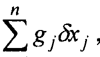
lead to a variation Sy of data and some parameter G = gjXj is a linear combination n
of Xj . Then, the maximal possible value ϊ \ SG \ , SG = ^ gj&j » over all variations
7 =1
tS = (^C| ,..., 5c„) which lead to variations Sy with || Sy ||< J0 is called the uncertainty of G corresponding to the data uncertainty SQ . Herein, the maximal possible value of
\ 3G \ is denoted by SGmax .
FIG. 2 shows a simple case of G = χ · , the inverse map the data uncertainty ball 200 of radius δ0 goes into some ellipsoid 210 in the parameter space. The uncertainty
Sx™ax is the half of the projection of this ellipsoid to the Xj -axis.
Once the dependence of the data on the parameters is linear, i .e.,
Figure imgf000009_0001
the variations dy and δχ are connected by the same matrix A - (a^ ) :
n
Sy, = j ijdXj , / = 1,..., N . (6)
7=1
Hence, it suffices to find ^7ma for a single value δ0 .
Mathematically, the problem of finding the uncertainty dGmax may be stated as the constrained maximization problem
Figure imgf000009_0002
with the positive definite symmetric matrix 5 = A CA called the information matrix.
n
When estimating the uncertainty of some parameter G =∑gjXj , other
7 = 1
parameters may be known with some accuracy (say the parameters with numbers n(\),..., n(k) ), i .e., their variations do not exceed some values
I δχη(1) \≤8 I = \,...k , (8) where k < n is the number of additional conditions.
The maximal value of | 5G | , 5G =
Figure imgf000010_0001
> over all variations δχ = (δχ{ δχη ) such that I \≤δ/ , I = 1,...& , which lead to data variations dy with || dy ||< £0 is called the conditional uncertainty of G . Herein the maximal value of conditional uncertainty of | 5G | is denoted by 5Gcond .
FIG. 3 shows an example of how the presence of additional conditions may improve the uncertainty. In particular, when k = n - \ and c>/ = 0 , / = 1,..., « - 1 , the conditional uncertainty 5xn cond equals 1 over the sensitivity of data to the parameter xn . Hence, the conditional uncertainty projection of the truncated ellipsoid 3 1 0 based on data uncertainty 200 may be smaller than the whole one 210 (FIG. 2).
Mathematically, the conditional uncertainty dGcond may be found by solving the constrained maximization problem
Figure imgf000010_0002
One non-limiting technique for solving the constrained maximization problem includes a general maximization problem arising in conditional linear uncertainty n analysis solution. For example, to determine the uncertainty of parameter G =∑gj*j
7 =1 while k conditions are imposed on the parameters with numbers n{Y),..., n{k) ,
0 < k≤ n . The generic problem requiring solution may be
G |-> max
Figure imgf000010_0003
x„ ) \< 6 I = \,..., k. where x is substituted for δχ for purposes of illustrating the generic solution.
Denoted by U the set on which the maximum of / (x) -\ G \ is sought; i.e. , U = {x: CAx,Ax) = SQ , | xn(l) \< δ,, I = l,...,k} .
The set U is closed and bounded; therefore, f(x) attains its greatest value on U . However, finding the greatest value on such a set straightforwardly is not a simple problem. We will represent U as the union of simpler sets on each of which the greatest value can be found by a standard method.
Let
S0 = {x : {CAx,Ax) = S }. (11) Let p = 0,...,k be the number of "active" conditions and let
1 < β{\) < ... < β{ρ) < k be the numbers of the selected conditions. Denoted by Bp may be the set of all integer-valued vectors β = {β{\),...,β{ρ)) with the indicated condition.
The set B comprises elements. Extending each β e B to a substitution of length k such that β(ρ + \) < ... < /?(&) ,thus keeping the former notation β for the extended vector.
For every p = 0,...,p and β Βρ introduce the set
Figure imgf000011_0001
(12)
Each set Sp β is the union of 2P pieces of (rt-/?)-dimensional spheres
Sp.p,s ~ ix e $0 '■ χη(β(1))~ 3ΐδβ(Ι) = 1»···, > I χη{β(ί)) \ < δβ(1)> I = P + -,k} , (13) where vectors s = (s ...,sp) have components st = ±1. There are 2P such vectors with their sets denoted by∑ .
Eventually,
Figure imgf000011_0002
p=0,..., eBp p= ,..., ε ρ se p
Let Mp β s equal the greatest value of f{x) on Sp p s if f(x) has the greatest value of this set and -∞ otherwise. Thus,
M = ma f(x) = max M o . (15)
U p,fi,s μ'μ' Now, the remaining question is that of finding the greatest value of f{x) on each Sp β s. Note that Sp β s is a manifold without boundary on the (o-^)-dimensional sphere
Sp.fi.s = {x e Ξ0η(β0)) =
Figure imgf000012_0001
,p} . (16) If f{x) attains the greatest value on Sp^s, this greatest value may occur only at a critical point (a point at which all partial derivatives are zero). All critical points of f(x) on Sp,/9,j may be found using the algorithm described below. If at least one of the critical points belongs to Sp β s, then Mp β s is set to be the maximum of values of f(x) at these critical points. Otherwise, M ρ β 5 =-∞.
Prior to applying the algorithm for finding critical points, the parameters may be rearranged such that the components with "active" conditions come first followed by the components with "inactive" conditions and then the "free" components. This rearrangement may be acheived by using the substitution σ defined as follows:
a{l) = n(PU)) = \,...,k, σ(1) = *(/), l = k + l,...,n. (17)
Interchanging columns may change the matrix A to the new matrix Aa with entries aj =aja(j Also, new variables x = xa{j) and the new vector g = ga(j) may be introduced so as to arrive at the following problem: find the critical values of
Figure imgf000012_0002
(18) on the set (CAaxa,Aaxa) = δΐ,χ" = s,Sm,I = 1, ···,/?. (1 )
Herein, when solving for the critical points, the notation will drop the
superscript σ and denote B - A CA and dt = SfSpa Using these notations, the critical n
points of the function |∑gjXj I on the set
]=\
{x : (Βχ,χ) = δ , x, = d l = \,...,p) (20) may be determined.
First, the variables may be separated into two groups: x = (x],...,xp,∑],...,∑m) , where m-n-p, and B may be expressed as a block matrix B Bo (21)
D C
where BQ is the (px p) -matrix, D is the (m /?) -matrix, and C is the (mxm)-matrix. The single value determinant of the matrix C corresponding to the unconstrained variables Z\,...,zm: C = UAU , where Λ == di g( ],..., m) , ' = (Μ/·/·) maybe
calculated, and then the new variables y = U z may be introduced. Next,
Zj =∑Uji)>i , since UU =U U = id .
Using the conditions xl=d , I = Ι,.,.,ρ, and passing to the new variable first condition may be transformed
Figure imgf000013_0001
d + 2∑Ciyi+∑Aiyi, where
Figure imgf000013_0002
Thus, the problem takes the form
Figure imgf000013_0003
This problem may be solved using the Lagrange multipliers. Let
(25)
Figure imgf000013_0004
The critical points are found from the conditions
dL m ( \
~~ =∑ gj+pUji - a^y, + 2c, j= 0 , (26)
Figure imgf000013_0005
U - lac m
Express y- - -1—— '- , (/,· = T" # ,·+„« from the first and insert them into the second:
Figure imgf000014_0001
Solving for a gives
Figure imgf000014_0002
if the expressions under the square roots are positive. If the square roots are negative, then the set on which the critical points are sought is empty and there are no critical points.
Once μ+ are defined, two critical points x± = (x†,..., x* ) (in the degenerate case they may coincide) may be obtained, where
Figure imgf000014_0003
After the maximization problem solution has been found, estimating the seismic
PP
parameters may proceed. If the reflection coefficients R (Θ) are known for a number of angles 6j , j = \,..., m , in some range, and the objective is to determine some parameter G depending on the velocities and densities, for example, the change of the P-impedance AJP = 1 P{ - //>2 = Vp\P\ - VpiPi i tnen oural 's t0 estimate the
P P
(conditional) uncertainty of G , provided that R (Θ) and some parameters are known with certain accuracy. This may be accomplished using the parameters:
x i =Vp, x2=AVp, x3=Vs, x4=AVs, 5=p, Χ6=ΔΡ.
After selected a set of parameters Vpj , Vp2, Vsi , Vs2, Pi , p2 (or point x\ , ... ,x6) and passing from the map (x, , · · · ,¾ ) \-> Rpp (θ^ Χο its linear approximation and
PP
replacing the parameter G with its linear analog, then the variations δχ, 5R , 5G are connected by the linear maps as follows:
Figure imgf000015_0001
(some of / may equal∞, which means that there may be no information about the corresponding parameter).
The result may depend on the set of parameters Vp-,Vp2,VS\,VS2, P\, p2 around which the map is linearized. For this example, there are four real sets of parameters (Table 1). The upper layer is shale and the lower layer is gas saturated sand.
Table 1. Parameters of layers (velocities in m/s and densities in g/cm3)
Figure imgf000015_0002
For this example, R (Θ) is given with an accuracy of 10%, ; i.e.,
\\5RPP ||≤0.1|| Rpp II, and only a priori information is available for the mean
VP , Vs, p , namely δ = £>3 = δ5 = 0. Under these conditions, using the above algorithm, the (conditional) uncertainty of the parameters
Wp, AVS, Δ , A(VP/VS), A(VPp), A{Vsp)
result in the four sets of parameters given in Table 2. Table 2. Uncertainty of parameters (velocities in m/s and densities in g/cm )
Figure imgf000016_0001
The uncertainties of the different parameters may be compared by rescaling. Hence each uncertainty may be divided by its corresponding range width, i.e., the difference between the maximal and minimal possible values of the parameter. If the uncertainty is greater than the range width, then the parameter cannot be determined. The uncertainties of the listed parameters divided by the corresponding range widths are given in Table 3.
Table 3. Uncertainty of parameters divided by the range width
Figure imgf000016_0002
Table 3 indicates that uncertainty may depend strongly on the situation. In set 1 , the uncertainty of all parameters except A{VPp) are very large. In sets 1 , 3 , and 4, the change in density exceeds the range width, thus indicating that the density may not be determined through inversion of seismic parameters. Finally, the change in P- impedance A{VPp) ma.y have a lower uncertainty than other uncertainty parameters. In contrast to the above example, uncertainty of parameters may be determined using additional information about density. Herein, it is assumed that the change of density on the reflecting boundary is known with some accuracy from some other source, for example, from inversion of borehole gravity information. Namely, assuming that δ6 = 0,...,0.5 (g / cm3 ) and evaluating again the (conditional) uncertainty of the same parameters.
FIG. 4 shows a method 400 according to one embodiment of the present disclosure. In step 41 0, borehole gravity information may be gathered for an earth formation where VSP information is available. In step 420, density information for the layers of the earth formation may be estimated using borehole gravity information. In step 430, seismic parameters may be estimated by inverting the seismic parameters based on VSP information while using the density information for the density parameters. In step 440, the seismic parameters may be estimated by jointly inverting the seismic parameters and the density information estimated using he borehole gravity information. In some embodiments, step 430 may be optional . In other embodiments, step 440 may be optional .
The results of method 400 using the information from Tables 1 -3 may be seen in Tables 4-6. Table 4 shows the improvement of uncertainty due to knowledge of
3 3
density where the density accuracy is improved from 0.5 g/cm to 0.05 g/cm . Table 5 shows the uncertainty when the density accuracy is 0.05 g/cm3. Table 6 shows the uncertainty for the density accuracy of 0.5 g/cm3. Tables 5 and 6 correspond to the unimproved density accuracy found in Table 2.
Table 4. Improvement of uncertainty due the knowledge of density. The ratios of uncertainties in the last four plots at 0.5 and 0.05.
Set AVP A VS Ap A{VP I VS ) A(Vpp) A(Vsp)
1 4.22 2.78 1 0.0 2.38 1 .56 2.37
2 3.95 3.09 6.91 1 .93 1 .08 1 .79
3 4.57 3.27 10.0 2.20 1 . 1 8 2. 1 1
4 4.25 3.89 1 0.0 1 .03 1 . 1 5 1 .21 Table 5 : Uncertainty for the density accuracy 0.05 g/cm (velocities in m/s and
3
densities in g/cm ).
Figure imgf000018_0001
Table 6: Uncertainty for the density accuracy 0.5 g/cm (velocities in m/s and
3
densities in g/cm ).
Figure imgf000018_0002
Generally, the velocity change parameters A Vp and A ^ may show greater improvement than other parameters. While impedance changes A(VPp) and
A(Vsp) ay show less improvement. The degree of improvement may correspond to how much a parameter is affected by accuracy of the density parameter. In some cases, improvement may occur in A{VP I VS ) , which is an indicator of the presence of oil/gas.
As shown in FIG. 5, certain embodiments of the present disclosure may be implemented with a hardware environment that includes an information processor 500, an information storage medium 5 10, an input device 520, processor memory 530, and may include peripheral information storage medium 540. The hardware
environment may be in the well, at the rig, or at a remote location. Moreover, the several components of the hardware environment may be distributed among those locations. The input device 520 may be any data reader or user input device, such as data card reader, keyboard, USB port, etc. The information storage medium 5 1 0 stores information provided by the detectors. Information storage medium 5 10 may include any non-transitory computer-readable medium for standard computer information storage, such as a USB drive, memory stick, hard disk, removable RAM, EPROMs, EAROMs, flash memories and optical disks or other commonly used memory storage system known to one of ordinary skill in the art including Internet based storage. Information storage medium 510 stores a program that when executed causes information processor 500 to execute the disclosed method. Information storage medium 5 10 may also store the formation information provided by the user, or the formation information may be stored in a peripheral information storage medium 540, which may be any standard computer information storage device, such as a USB drive, memory stick, hard disk, removable RAM, or other commonly used memory storage system known to one of ordinary skill in the art including Internet based storage. Information processor 500 may be any form of computer or mathematical processing hardware, including Internet based hardware. When the program is loaded from information storage medium 510 into processor memory 530 (e.g. computer RAM), the program, when executed, causes information processor 500 to retrieve detector information from either information storage medium 510 or peripheral information storage medium 540 and process the information to estimate a parameter of interest. Information processor 500 may be located on the surface or downhole.
While the foregoing disclosure is directed to the one mode embodiments of the disclosure, various modifications will be apparent to those skilled in the art. It is intended that all variations be embraced by the foregoing disclosure.

Claims

1. A method of evaluating an earth formation, the method comprising:
estimating at least one parameter of interest of the earth formation using seismic parameters and density information, wherein a processor uses the density information to reduce uncertainty in the seismic parameters.
2. The method of claim 1 , further comprising:
estimating the density information using gravity log information.
3. The method of claim 2, wherein the gravity log information is obtained from a borehole gravity log.
4. The method of claim 2, wherein the gravity log information includes at least one of: i) vertical gravity component information and ii) horizontal gravity component information.
5. The method of claim 2, wherein estimating the density information includes performing an inversion of the gravity log information.
6. The method of claim 5, further comprising:
inverting the vertical seismic parameters jointly with the inversion of the gravity log information.
7. The method of claim 1 , wherein the earth formation comprises at least a first layer and a second layer.
8. The method of claim 7, wherein the at least one parameter of interest includes at least one of: i) a P-wave velocity in the first formation layer ii) a P-wave velocity in the second formation layer, in) a difference between the P-wave velocity in the first formation layer and the P-wave velocity in the second formation layer, iv) an S- wave velocity in the first formation layer, v) an S-wave velocity in the second formation layer, vi) a difference between the S-wave velocity in the first formation layer and the S-wave velocity in the second formation layer vii) a density of the first formation layer, viii) a density of the second formation layer, ix) a difference between the density of the first formation layer and the density of the second formation layer, x) elastic constants of the first formation, and xi) elastic constants of the second formation.
9. The method of claim 1 , wherein the seismic parameters correspond to a first borehole and the density information corresponds to a second borehole.
10. The method of claim 1 , wherein the seismic parameters include vertical seismic profiling information.
1 1. An apparatus for evaluating an earth formation, the apparatus comprising: a gravity data log; and
a processor configured to estimate at least one parameter of interest of the earth formation using seismic parameters and density information, wherein the processor uses the density information to reduce uncertainty in the seismic parameters.
12. The apparatus of claim 1 1 , the processor further configured to:
estimate the density information using gravity log information.
13. The apparatus of claim 12, wherein the gravity log information is obtained from a borehole gravity log.
14. The apparatus of claim 12, wherein the gravity log information includes at least one of: i) vertical gravity component information and ii) horizontal gravity component information.
15. The apparatus of claim 12, wherein density information is estimated using inverted gravity log information.
16. The apparatus of claim 15, the processor being further configured to: invert the vertical seismic parameters jointly with the inversion of the gravity log information.
1 7. The apparatus of claim 1 1 , wherein the earth formation comprises at least a first layer and a second layer.
1 8. The apparatus of claim 1 7, wherein the at least one parameter of interest includes at least one of: i) a P-wave velocity in a first formation layer ii) a P-wave velocity in a second formation layer, iii) a difference between the P-wave velocity in the first formation layer and the P-wave velocity in the second formation layer, iv) an S-wave velocity in the first formation layer, v) an S-wave velocity in the second formation layer, vi) a difference between the S-wave velocity in the first formation layer and the S-wave velocity in the second formation layer vii) a density of the first formation layer, viii) a density of the second formation layer, and ix) a difference between the density of the first formation layer and the density of the second formation layer, x) an elastic constant of the first formation, and xi) an elastic constant of the second formation.
19. The apparatus of claim 1 1 , wherein the seismic parameters correspond to a first borehole and the density information corresponds to a second borehole.
20. The apparatus of claim 1 1 , wherein the seismic parameters include vertical seismic profiling information
PCT/RU2011/000259 2011-04-22 2011-04-22 Increasing the resolution of vsp ava analysis through using borehole gravity information Ceased WO2012144922A1 (en)

Priority Applications (6)

Application Number Priority Date Filing Date Title
GB1316308.4A GB2502924A (en) 2011-04-22 2011-04-22 Increasing the resolution of VSP AVA analysis through using borehole gravity information
CA2830890A CA2830890A1 (en) 2011-04-22 2011-04-22 Increasing the resolution of vsp ava analysis through using borehole gravity information
BR112013026528A BR112013026528A2 (en) 2011-04-22 2011-04-22 "method and apparatus for assessing earth formation"
PCT/RU2011/000259 WO2012144922A1 (en) 2011-04-22 2011-04-22 Increasing the resolution of vsp ava analysis through using borehole gravity information
US13/382,330 US20120271552A1 (en) 2011-04-22 2011-04-22 Increasing the resolution of vsp ava analysis through using borehole gravity information
NO20131177A NO20131177A1 (en) 2011-04-22 2013-09-03 Increase the resolution of VSP AVA analysis using borehole gravity information

Applications Claiming Priority (1)

Application Number Priority Date Filing Date Title
PCT/RU2011/000259 WO2012144922A1 (en) 2011-04-22 2011-04-22 Increasing the resolution of vsp ava analysis through using borehole gravity information

Publications (2)

Publication Number Publication Date
WO2012144922A1 true WO2012144922A1 (en) 2012-10-26
WO2012144922A8 WO2012144922A8 (en) 2013-02-07

Family

ID=47021983

Family Applications (1)

Application Number Title Priority Date Filing Date
PCT/RU2011/000259 Ceased WO2012144922A1 (en) 2011-04-22 2011-04-22 Increasing the resolution of vsp ava analysis through using borehole gravity information

Country Status (6)

Country Link
US (1) US20120271552A1 (en)
BR (1) BR112013026528A2 (en)
CA (1) CA2830890A1 (en)
GB (1) GB2502924A (en)
NO (1) NO20131177A1 (en)
WO (1) WO2012144922A1 (en)

Families Citing this family (5)

* Cited by examiner, † Cited by third party
Publication number Priority date Publication date Assignee Title
US9835481B2 (en) 2014-06-27 2017-12-05 Baker Hughes, A Ge Company, Llc Multichannel correlation analysis for displacement device
FR3043227A1 (en) * 2015-11-04 2017-05-05 Services Petroliers Schlumberger
GB2555375B (en) * 2016-09-30 2020-01-22 Equinor Energy As Improved methods relating to quality control
EP3526628B1 (en) 2016-10-14 2022-03-23 Services Pétroliers Schlumberger Geologic structural model generation
CN113009559B (en) * 2021-03-02 2022-02-18 中国科学院地质与地球物理研究所 Seismic Evaluation Method Based on Multi-Type Geophysical Data

Citations (5)

* Cited by examiner, † Cited by third party
Publication number Priority date Publication date Assignee Title
WO2003023447A2 (en) * 2001-09-07 2003-03-20 Conocophillips Company A nonlinear constrained inversion method to determine base of salt interface from gravity and gravity tensor data
US20040172199A1 (en) * 1999-04-02 2004-09-02 Conocophillips Company Modeling gravity and tensor gravity data using poisson's equation for airborne, surface and borehole applications
US20080059075A1 (en) * 2006-09-04 2008-03-06 Daniele Colombo Methods and apparatus for geophysical exploration via joint inversion
US20090164188A1 (en) * 2007-12-21 2009-06-25 Tarek Habashy Method for upscaling a reservoir model using deep reading measurements
WO2010006052A2 (en) * 2008-07-10 2010-01-14 Schlumberger Canada Limited System and method for generating true depth seismic surveys

Family Cites Families (29)

* Cited by examiner, † Cited by third party
Publication number Priority date Publication date Assignee Title
US4397181A (en) * 1981-08-21 1983-08-09 Mobil Oil Corporation Method for determining fluid saturation in a subsurface formation
US4932003A (en) * 1982-05-19 1990-06-05 Exxon Production Research Company Acoustic quadrupole shear wave logging device
US4517836A (en) * 1983-10-25 1985-05-21 Mobil Oil Corporation Method for determining oil saturation in a subsurface formation
US4809239A (en) * 1987-07-14 1989-02-28 Schlumberger Technology Corporation Method for evaluating parameters related to the elastic properties of subsurface earth formations
US5218864A (en) * 1991-12-10 1993-06-15 Conoco Inc. Layer density determination using surface and deviated borehole gravity values
US5302782A (en) * 1992-06-15 1994-04-12 Southwest Research Institute Three-component borehole wall-locking seismic detector
US5889729A (en) * 1996-09-30 1999-03-30 Western Atlas International, Inc. Well logging data interpretation systems and methods
US5862513A (en) * 1996-11-01 1999-01-19 Western Atlas International, Inc. Systems and methods for forward modeling of well logging tool responses
US6278948B1 (en) * 1999-04-02 2001-08-21 Conoco Inc. Method for gravity and magnetic data inversion using vector and tensor data
US6694261B1 (en) * 1999-06-07 2004-02-17 Conoco Inc. Method for identification of shallow water flow hazards using marine seismic data
US6473696B1 (en) * 2001-03-13 2002-10-29 Conoco Inc. Method and process for prediction of subsurface fluid and rock pressures in the earth
CA2519947A1 (en) * 2003-03-21 2004-10-07 Mark E. Ander Gravity techniques for drilling and logging
US20060070432A1 (en) * 2003-03-21 2006-04-06 Ander Mark E Gravity techniques for drilling and logging
WO2004095077A1 (en) * 2003-04-23 2004-11-04 Commonwealth Scientific And Industrial Research Organisation Method for predicting pore pressure
EP1517142A1 (en) * 2003-09-16 2005-03-23 Nederlandse Organisatie voor toegepast-natuurwetenschappelijk Onderzoek TNO An acoustic testing apparatus for testing a laminate material and an acoustic testing method for testing a laminate material
US7349807B2 (en) * 2004-03-08 2008-03-25 Geomechanics International, Inc. Quantitative risk assessment applied to pore pressure prediction
US7257490B2 (en) * 2005-06-03 2007-08-14 Baker Hughes Incorporated Pore-scale geometric models for interpretation of downhole formation evaluation data
US7299132B2 (en) * 2005-08-08 2007-11-20 Schlumberger Technology Corp. Method and system for pre-drill pore pressure prediction
US7626886B2 (en) * 2006-06-06 2009-12-01 Baker Hughes Incorporated P-wave anisotropy determination using borehole measurements
US7983885B2 (en) * 2006-12-29 2011-07-19 Terratek, Inc. Method and apparatus for multi-dimensional data analysis to identify rock heterogeneity
US8113042B2 (en) * 2007-09-28 2012-02-14 Schlumberger Technology Corporation Gravity measurment methods for monitoring reservoirs
CA2707526C (en) * 2008-01-08 2016-01-26 Exxonmobil Upstream Research Company Spectral shaping inversion and migration of seismic data
US8527248B2 (en) * 2008-04-18 2013-09-03 Westerngeco L.L.C. System and method for performing an adaptive drilling operation
US8576659B2 (en) * 2009-03-03 2013-11-05 Baker Hughes Incorporated Method and apparatus for acoustic impedance and P-wave anisotropy measurements
FR2949586B1 (en) * 2009-08-26 2011-09-23 Inst Francais Du Petrole METHOD FOR OPERATING A PETROLEUM TANK FROM AN OPTIMIZED HISTORICAL SETTING
US8494827B2 (en) * 2009-09-25 2013-07-23 Exxonmobil Upstream Research Company Method of predicting natural fractures and damage in a subsurface region
US8818779B2 (en) * 2009-12-21 2014-08-26 Baker Hughes Incorporated System and methods for real-time wellbore stability service
US8700372B2 (en) * 2011-03-10 2014-04-15 Schlumberger Technology Corporation Method for 3-D gravity forward modeling and inversion in the wavenumber domain
US8725479B2 (en) * 2011-11-30 2014-05-13 Baker Hughes Incorporated Use of monte carlo simulations for establishing correlations and their uncertainties

Patent Citations (5)

* Cited by examiner, † Cited by third party
Publication number Priority date Publication date Assignee Title
US20040172199A1 (en) * 1999-04-02 2004-09-02 Conocophillips Company Modeling gravity and tensor gravity data using poisson's equation for airborne, surface and borehole applications
WO2003023447A2 (en) * 2001-09-07 2003-03-20 Conocophillips Company A nonlinear constrained inversion method to determine base of salt interface from gravity and gravity tensor data
US20080059075A1 (en) * 2006-09-04 2008-03-06 Daniele Colombo Methods and apparatus for geophysical exploration via joint inversion
US20090164188A1 (en) * 2007-12-21 2009-06-25 Tarek Habashy Method for upscaling a reservoir model using deep reading measurements
WO2010006052A2 (en) * 2008-07-10 2010-01-14 Schlumberger Canada Limited System and method for generating true depth seismic surveys

Also Published As

Publication number Publication date
US20120271552A1 (en) 2012-10-25
NO20131177A1 (en) 2013-10-02
GB201316308D0 (en) 2013-10-30
BR112013026528A2 (en) 2016-12-27
GB2502924A (en) 2013-12-11
CA2830890A1 (en) 2012-10-26
WO2012144922A8 (en) 2013-02-07

Similar Documents

Publication Publication Date Title
RU2602409C2 (en) Inversion anisotropy multi-well system
Dutta Geopressure prediction using seismic data: Current status and the road ahead
US20220351037A1 (en) Method and system for spectroscopic prediction of subsurface properties using machine learning
RU2457513C2 (en) Methods and systems for processing microseismic data
US20180203144A1 (en) Interferometric Microseismic Imaging Methods and Apparatus
AU2013392659B2 (en) Methods and systems for seismic data analysis using a tilted transversely isotropic (TTI) model
US8792302B2 (en) Estimating anisotropic parameters
WO2010111077A1 (en) Methods to estimate subsurface deviatoric stress characteristics from borehole sonic log anisotropy directions and image log failure directions
CN109563736A (en) The estimation of horizontal stress and nonlinear constant in the anisotropic formation of interlayer carbonate horizon in such as organic shale reservoir
NO20130263A1 (en) Depiction of the subsoil structure in front of the drill bit when logging during drilling
NO337603B1 (en) System and method for estimating main subsurface voltages from seismic reflection data
US20080162050A1 (en) Method for interpreting seismic data and controlled source electromagnetic data to estimate subsurface reservoir properties
GB2491346A (en) Three dimensional full-wavefield seismic tomography for use in mining or in extraction of metalliferous mineral and/or diamond deposits
NO20120002A1 (en) Determination of differential stress based on formation curvature and mechanical units using borehole logs
RU2711178C1 (en) Method 3d for forecasting properties and structure of geological objects based on computer analysis of the surface properties of surface geological and geophysical fields
US8064287B2 (en) Method for interpreting seismic data and controlled source electromagnetic data to estimate subsurface reservoir properties
CN105683781A (en) Method for transforming reservoir property into seismic attribute for identifying hydrocarbon and lithology
WO2025122409A1 (en) Method for calibrating prestack seismic inversion using fully connected neural networks
Aminzadeh et al. Fundamentals of petroleum geophysics
US20120271552A1 (en) Increasing the resolution of vsp ava analysis through using borehole gravity information
Cao et al. Integrated detection of fractures and caves in carbonate fractured-vuggy reservoirs based on seismic data and well data
Ezhov et al. Application of special well logging techniques for geomechanical model imporvement in naturally fractured reservoirs
Arsalan et al. Application of extended elastic impedance: A case study from Krishna-Godavari Basin, India
Chatterjee et al. Geomechanics in unconventional reservoir: a new approach to drilling integrating advanced acoustic measurements and formation evaluation
Rodríguez et al. Automatic interpretation of geophysical well logs

Legal Events

Date Code Title Description
WWE Wipo information: entry into national phase

Ref document number: 13382330

Country of ref document: US

121 Ep: the epo has been informed by wipo that ep was designated in this application

Ref document number: 11788237

Country of ref document: EP

Kind code of ref document: A1

ENP Entry into the national phase

Ref document number: 1316308

Country of ref document: GB

Kind code of ref document: A

Free format text: PCT FILING DATE = 20110422

WWE Wipo information: entry into national phase

Ref document number: 1316308.4

Country of ref document: GB

ENP Entry into the national phase

Ref document number: 2830890

Country of ref document: CA

NENP Non-entry into the national phase

Ref country code: DE

REG Reference to national code

Ref country code: BR

Ref legal event code: B01A

Ref document number: 112013026528

Country of ref document: BR

122 Ep: pct application non-entry in european phase

Ref document number: 11788237

Country of ref document: EP

Kind code of ref document: A1

ENP Entry into the national phase

Ref document number: 112013026528

Country of ref document: BR

Kind code of ref document: A2

Effective date: 20131015