WO2012141083A1 - Portable terminal device and method for controlling same - Google Patents
Portable terminal device and method for controlling same Download PDFInfo
- Publication number
- WO2012141083A1 WO2012141083A1 PCT/JP2012/059458 JP2012059458W WO2012141083A1 WO 2012141083 A1 WO2012141083 A1 WO 2012141083A1 JP 2012059458 W JP2012059458 W JP 2012059458W WO 2012141083 A1 WO2012141083 A1 WO 2012141083A1
- Authority
- WO
- WIPO (PCT)
- Prior art keywords
- touch
- touch signal
- signal
- mode
- terminal device
- Prior art date
Links
Images


Classifications
-
- G—PHYSICS
- G06—COMPUTING; CALCULATING OR COUNTING
- G06F—ELECTRIC DIGITAL DATA PROCESSING
- G06F3/00—Input arrangements for transferring data to be processed into a form capable of being handled by the computer; Output arrangements for transferring data from processing unit to output unit, e.g. interface arrangements
- G06F3/01—Input arrangements or combined input and output arrangements for interaction between user and computer
- G06F3/03—Arrangements for converting the position or the displacement of a member into a coded form
- G06F3/041—Digitisers, e.g. for touch screens or touch pads, characterised by the transducing means
- G06F3/0416—Control or interface arrangements specially adapted for digitisers
- G06F3/0418—Control or interface arrangements specially adapted for digitisers for error correction or compensation, e.g. based on parallax, calibration or alignment
- G06F3/04186—Touch location disambiguation
-
- H—ELECTRICITY
- H04—ELECTRIC COMMUNICATION TECHNIQUE
- H04M—TELEPHONIC COMMUNICATION
- H04M2250/00—Details of telephonic subscriber devices
- H04M2250/22—Details of telephonic subscriber devices including a touch pad, a touch sensor or a touch detector
Definitions
- the present invention relates to a mobile terminal device and a control method for the mobile terminal device, and more particularly to a technique for suppressing malfunction in a mobile terminal device including a display panel and a touch panel arranged on a viewer-side surface of the display panel.
- a mobile terminal device such as a mobile phone or a smartphone is provided with a touch panel, and an input to the mobile terminal device is performed by a touch operation performed on the touch panel.
- a portable terminal device is usually not provided with a cover. Therefore, when the mobile terminal device is accommodated in a bag or the like, if there is an unintended contact with the touch panel, the mobile terminal device may malfunction.
- a malfunction of the mobile terminal device due to an unintentional touch on the touch panel using a two-point touch operation on the touch panel is disclosed. A method of suppressing this is conceivable.
- the present invention has been completed based on the above situation, and provides a technique for suppressing a malfunction of a mobile terminal device due to unnecessary contact with a touch panel by a simple method.
- a mobile terminal device of the present invention is a touch panel disposed on a display panel and an observer side surface of the display panel, and generates a touch signal indicating a touch point as coordinates.
- a touch panel a display data generation circuit for generating display data for displaying an image on the display panel, supplying the display data to the display panel, and monitoring the display data, the display data changing by a predetermined amount or more
- the first touch signal is received from the touch panel in a state where the state is not continued for the first predetermined period or more, and the second touch signal is received from the touch panel within the second predetermined period from the reception of the first touch signal.
- a touch panel control circuit that uses the second touch signal as an effective input signal to the portable terminal device. That.
- the first touch signal is received from the touch panel in a state in which the display data does not change by a predetermined amount or more for a first predetermined period or more, and from the touch panel within the second predetermined period from the reception of the first touch signal.
- the second touch signal is used as an effective input signal to the mobile terminal device. For this reason, for example, even when the mobile terminal device has an unnecessary contact with the touch panel in a standby state such as the power saving mode, the contact is not an effective contact with the mobile terminal device. As a result, malfunction of the mobile terminal device due to unnecessary contact with the mode touch panel can be suppressed by a simple method.
- the mobile terminal device further includes a backlight that illuminates the display panel, a mode switching circuit that switches between a display mode for turning on the backlight and a power saving mode for turning off the backlight,
- the touch panel control circuit switches from the display mode to the power saving mode when the state where the display data does not change by the predetermined amount or more continues for the first predetermined period or more, and receives the first touch signal in the power saving mode.
- the mode switching circuit is controlled to switch from the power saving mode to the display mode based on receiving the second touch signal within a second predetermined period from the reception of the first touch signal. May be. According to this configuration, malfunction from the power saving mode to the display mode can be suppressed.
- the touch panel control circuit uses the second touch signal as the valid input signal and invalidates the first touch signal. Good.
- the second touch signal is validated on the condition that the first touch signal and the second touch signal are received. Therefore, malfunction can be suppressed by a simple method.
- the touch panel control circuit when the touch panel control circuit receives the first touch signal within the first predetermined period from when the display data changes by the predetermined amount or more, the touch panel control circuit receives the first touch signal as the effective input signal. You may make it.
- effective input when the display data changes by a predetermined amount or more, effective input can be made to the mobile terminal device only with the first touch signal.
- the touch panel has a handwriting input mode in which handwriting input is possible as an input mode
- the touch panel control circuit is configured such that the state where the display data does not change more than the predetermined amount is continued for the first predetermined period or longer.
- the second touch signal is validated after the user is authenticated by the first touch signal corresponding to the handwritten input. Therefore, in a power saving mode or the like, malfunction of the mobile terminal device due to unnecessary contact with the touch panel can be suppressed by a simple method, and user authentication can be easily and suitably performed using the touch panel. .
- the touch panel may include a predetermined touch area for generating the first touch signal and the second touch signal.
- the predetermined touch area may include a first touch area for generating the first touch signal and a second touch area for generating the second touch signal.
- the touch area may be set to a different location, it is possible to suitably suppress malfunction caused by unnecessary contact that repeatedly occurs at the same location.
- the method of the present invention is a control method of a mobile terminal device including a display panel and a touch panel disposed on a viewer-side surface of the display panel, according to the coordinates of touch points on the touch panel.
- a touch signal generating step for generating a touch signal ; a display data generating step for generating display data for displaying an image on the display panel; a display data monitoring step for monitoring the display data; and a predetermined amount of the display data.
- the first touch signal is received from the touch panel in a state in which the state does not change more than the first predetermined period, and the second touch signal is received from the touch panel within the second predetermined period from the reception of the first touch signal. Based on the above, the second touch signal is used as an effective input signal to the portable terminal device. Including the door.
- the method further includes a mode switching step of switching between a display mode for turning on a backlight for illuminating the display panel provided in the mobile terminal device and a power saving mode for turning off the backlight, and the mode switching step. Is switched from the display mode to the power saving mode when the state in which the display data does not change more than the predetermined amount continues for the first predetermined period, receives a first touch signal in the power saving mode, and Switching from the power saving mode to the display mode may be included based on the reception of the second touch signal within the second predetermined period from the reception of the first touch signal.
- the touch signal processing step may use the second touch signal as the valid input signal and invalidate the first touch signal on condition that the first touch signal and the second touch signal are received. May be included.
- the touch panel has a handwriting input mode capable of handwriting input as an input mode
- the touch signal processing step includes a state in which the display data does not change more than the predetermined amount for the first predetermined period or longer.
- the block which shows schematically the electric constitution of the portable terminal device which concerns on this invention 6 is a flowchart showing input processing of a touch panel in the first embodiment.
- the top view which shows the touch aspect of another touch panel The top view which shows the touch aspect of another touch panel
- the top view which shows the touch aspect of another touch panel is a flowchart showing input processing of a touch panel in the first embodiment.
- the top view which shows the touch aspect of another touch panel The top view which shows the touch aspect of another touch panel
- Embodiment 1 of a portable terminal device according to the present invention will be described with reference to FIGS.
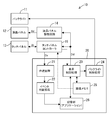
- FIG. 1 is a block diagram schematically showing an electrical configuration of the mobile terminal device 10.
- the mobile terminal device 10 is, for example, a mobile phone, a PDA, a smartphone, a tablet-type multifunctional mobile terminal device, or the like.
- the mobile terminal device 10 includes a backlight 11, a liquid crystal panel (an example of a display panel) 12, a touch panel 13, a liquid crystal panel drive circuit 14, a touch panel controller 15, a calculation unit 20, and the like.
- the backlight 11 is provided behind the liquid crystal panel 12, and illuminates the liquid crystal panel 12 from behind.
- the liquid crystal panel 12 is, for example, a TFT color liquid crystal panel, and displays a color image in accordance with a liquid crystal drive signal from the liquid crystal panel drive circuit 14.
- the liquid crystal panel drive circuit 14 receives display data Dd for displaying a color image from the arithmetic unit 20, generates a liquid crystal drive signal Sd including a data signal (gradation voltage) corresponding to the display data Dd, and outputs the liquid crystal drive signal. Sd is supplied to the liquid crystal panel 12.
- the touch panel 13 is disposed on the surface of the liquid crystal panel 12 on the user (observer) side, and generates a touch signal St including a touch point by the user as coordinate information. That is, the touch panel 13 is a coordinate detection type touch panel, and includes, for example, opposing transparent electrodes for the X coordinate and the Y coordinate. A transparent resistive film is formed on each transparent electrode. Touching each transparent resistive film with a finger or a pen or the like makes touch panel input, and a touch signal (voltage signal) corresponding to the X and Y coordinates. St is generated.
- the touch panel 13 has a handwriting input mode in which handwriting input is possible as an input mode.
- a touch panel controller 15 (an example of a touch panel control circuit) 15 supplies a reference voltage for detection to the touch panel 13.
- the touch panel controller 15 receives a touch signal St that is a divided voltage from the reference voltage from the touch panel 13.
- the touch signal St is converted into, for example, a digital coordinate signal Dz.
- the touch panel controller 15 receives the display data Dd from the arithmetic unit 20 and monitors the change of the display data Dd.
- the first touch signal (corresponding to the first touch signal) is received in a state in which the display data Dd does not change by a predetermined amount or more, and the first touch signal is received. 2
- the second touch signal is used as an effective input signal to the mobile terminal device.
- the touch panel controller 15 performs the second touch on the condition that the second touch signal is received within the second predetermined period from the reception of the first touch signal and the first touch signal.
- the signal is an effective input signal.
- the touch panel controller 15 may monitor the display data Dd by monitoring data in the image memory 15 as indicated by a broken line in FIG.
- the “predetermined amount” is a display data amount corresponding to a very small area on the liquid crystal panel 12 that is periodically updated, for example, a clock display.
- the state in which the display data Dd does not change by a predetermined amount or more can be said to be a display state of the liquid crystal panel 12 in which only such a clock display is periodically updated.
- the “first predetermined period” is, for example, 60 seconds.
- the “second predetermined period” is, for example, 3 seconds. Note that these “predetermined amount”, “first predetermined period”, and “second predetermined period” are examples, and may be appropriately changed according to user settings.
- the “effective input signal” means a signal that can cause the mobile terminal device to perform some operation. For example, it means a signal for starting a mobile terminal device in a power saving mode (sleep state).
- the calculation unit 20 performs overall control related to the image display of the mobile terminal device 10.
- the computing unit 20 includes a coordinate processing unit 21, an event determination processing unit 22, a display control processing unit 23, a backlight control processing unit 24, an image memory 25, a storage unit 26, and the like.
- the coordinate processing unit 21 receives the digital coordinate signal Dz from the touch panel controller 15 and performs coordinate processing using the digital coordinate signal Dz.
- the event determination processing unit 22 determines an event designated by the panel touch based on the coordinate-processed signal, and designates an application for executing the event.
- Various applications are stored in the storage unit 26 such as a hard disk.
- a display control processing unit (an example of a mode switching circuit) 23 generates display data Dd associated with execution of various applications and controls lighting of the backlight 11 via the backlight control processing unit 24. Specifically, the display control processing unit 23 switches between a display mode in which the backlight 11 is turned on and a power saving mode in which the backlight 11 is turned off.
- the “display mode” is a normal mode in which the user performs various applications.
- the “power saving mode” is a mode in which the mobile terminal device 10 is in a standby state. While the backlight 11 is turned off, the drive signal Sd from the liquid crystal panel drive circuit 14 to the liquid crystal panel 12 is stopped, and the liquid crystal panel 12 stops displaying images.
- the touch panel controller 15 switches from the display mode to the power saving mode when the state in which the display data Dd does not change by a predetermined amount or more continues for the first predetermined period or longer.
- the touch panel controller 15 receives the first touch signal St1 in the power saving mode and receives the second touch signal St2 within the second predetermined period from the reception of the first touch signal St1, the touch panel controller 15 switches from the power saving mode to the display mode.
- the display control processing unit 23 is controlled to switch to
- the image memory 25 is composed of, for example, a VRAM and is used when generating application display data Dd.
- the image memory 25 temporarily stores image data for at least one display screen of the liquid crystal panel 12.
- the storage unit 26 stores various programs executed by the arithmetic unit 20.
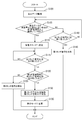
- FIG. 2 is a schematic flowchart relating to “touch panel input processing”.
- FIG. 3 is a schematic plan view showing touch points on the touch panel.
- the “touch panel input process” is executed at predetermined time intervals by the touch panel controller 15 according to a predetermined program.
- the touch panel controller 15 monitors whether the display data Dd has changed (step S100: YES).
- the touch panel controller 15 determines whether or not the state in which the display data Dd does not change by a predetermined amount or more continues for the first predetermined period (step S105).
- step S105 When it is determined that the state in which the display data Dd does not change by a predetermined amount or more continues for the first predetermined period (step S105: YES), the touch panel controller 15 controls the display control processing unit 23 to change the operation mode to the display mode. Is switched to the power saving mode (step S110). Next, in the power saving mode (after the first predetermined period), it is determined whether or not the touch signal (first touch signal) St1 of the first point P1 (see FIG. 3) has been received (step S115).
- step S115 When the first point touch signal St1 is received (step S115: YES), the second point P2 (see FIG. 3) touch signal (second touch signal) within the second predetermined period from the reception of the first point touch signal St1. ) It is determined whether or not St2 has been received (step S120).
- step S120 When it is determined that the second touch signal St2 is received within the second predetermined period (step S120: YES), the first touch signal St1 is invalidated and the second touch signal St2 is validated ( Step S130). In other words, the touch panel controller 15 regards the second touch signal St2 as a substantial first touch signal instead of the invalidated first touch signal St1.
- the touch panel controller 15 controls the display control processing unit 23 to switch from the power saving mode to the display mode, for example, as described above (step S135). ). Accordingly, the display control processing unit 23 turns on the backlight 11 and displays a predetermined image on the liquid crystal panel 12 via the liquid crystal panel drive circuit 14.
- the second touch signal St2 is invalidated (step S125).
- Step S105 when it is determined that the state in which the display data Dd does not change by a predetermined amount or more is not continued for the first predetermined period (Step S105: NO), the first touch signal St1 is received within the first predetermined period. It is determined whether or not (step S140). When the first touch signal St1 is received (step S140: YES), the first touch signal St1 is validated (step S145). Note that the process of step S140 is also performed when the first predetermined period has not elapsed since the display data Dd changed by a predetermined amount or more.
- the first touch point (coordinate) P ⁇ b> 1 and the second touch point (coordinate) P ⁇ b> 2 are arbitrary locations (coordinates) on the touch panel 13. Is done.
- the touch panel controller 15 detects the first touch signal (first touch) in a state in which the display data Dd does not change more than a predetermined amount for a first predetermined period or longer. Signal) St1, and when the second touch signal (second touch signal) St2 is received within the second predetermined period from the reception of the first touch signal St1, the first touch signal St1 is invalidated.
- the second touch signal St2 is used as an effective input signal to the mobile terminal device 10. Therefore, malfunction of the mobile terminal device 10 due to unnecessary contact with the touch panel 13 can be suppressed by a simple method.
- the touch panel controller 15 receives the first touch signal St1 in the power saving mode and receives the second touch signal St2 within the second predetermined period from the reception of the first touch signal St1.
- the display control processing unit 23 mode switching circuit
- the display control processing unit 23 is controlled to switch from the mode to the display mode. Therefore, it is suppressed that the backlight 11 is turned on by unnecessary contact with the touch panel 13. That is, it is possible to suppress unnecessary power consumption in the power saving mode. Further, when returning from the power saving mode to the display mode, it is not necessary to separately provide a switch for returning, and the user does not need to operate the switch.
- FIG. 4 is a schematic flowchart illustrating “touch panel input processing” according to the second embodiment.
- FIG. 5 is a schematic plan view showing touch points on the touch panel in the second embodiment. Since the second embodiment and the first embodiment are different only in the process related to the “touch panel input process”, only the difference from the first embodiment will be described below, and the same step number is assigned to the same process as the first embodiment. The description is omitted.
- the first touch signal St1 is generated according to the gesture pattern GP created by handwriting input, as shown in FIG. 5, instead of the input of the point P1. Further, user authentication processing is performed using the gesture pattern GP.
- the touch panel controller 15 changes the operation mode to the power saving mode when the state where the display data Dd does not change by a predetermined amount or more continues for the first predetermined period or longer (step S105: YES).
- the input mode of the touch panel 13 is set to the handwriting input mode (step S205).
- the 1st touch signal St1 according to handwriting input is received after progress of the 1st predetermined period, ie, when gesture pattern GP (refer FIG. 5) is input into the touch panel 13 (step S210: YES)
- handwriting An input authentication process is performed (step S215).
- the authentication process is performed, for example, by collating a handwritten input gesture pattern GP with a pre-registered gesture pattern.
- step S220 If the handwritten input gesture pattern GP is authenticated (step S220: YES), the processing from step S120 to step S135 is performed. On the other hand, when the gesture pattern GP is not authenticated (step S220: NO), the gesture pattern GP is invalidated (step S225). In step S130 in the second embodiment, the gesture pattern GP is invalidated only as a function of the first touch signal.
- step S105 when it is determined in step S105 that the state in which the display data Dd does not change by a predetermined amount or more is not continued for the first predetermined period (step S105: NO), one point within the first predetermined period is obtained as in the first embodiment. It is determined whether the eye touch signal St1 has been received (step S140). When the first touch signal St1 is received (step S140: YES), the first touch signal St1 is validated (step S145).
- a handwritten input gesture pattern GP is input.
- the gesture pattern GP is authenticated and the second touch signal St2 is input within the second predetermined period, the second touch signal St2 is validated and the operation mode is returned to the display mode.
- the second touch signal St2 is validated after the user is authenticated by the gesture pattern GP that is the first touch panel input. Therefore, malfunctions of the mobile terminal device 10 due to unnecessary contact with the touch panel 13 in the power saving mode or the like can be further suppressed. In addition, user authentication can be easily and suitably performed using the touch panel 13.
- the touch points P1 and P2 and the gesture pattern GP are formed on the touch panel 13 is arbitrary, but is not limited thereto.
- the touch points P ⁇ b> 1 and P ⁇ b> 2 and the gesture pattern GP may be formed in a predetermined area 13 ⁇ / b> A on the touch panel 13. That is, the touch panel 13 may include a predetermined touch area 13A for generating the first touch signal St1 and the second touch signal St2.
- the predetermined touch area 13 ⁇ / b> A is preferably set within a range in which the thumb can reach when the user holds the mobile terminal device 10 with one hand.
- the operation of returning from the power saving mode to the display mode can be performed with one thumb, and user operability is improved.
- the predetermined touch area 13B in FIG. 7 regardless of the holding direction of the mobile terminal device 10, that is, when the display screen is placed vertically (portrait mode), it is placed horizontally. In both cases (landscape mode), it is preferable that the range is within the reach of the thumb. In this case, user operability is further improved.
- the user may be allowed to set a predetermined area on the touch panel 13 at an arbitrary location.
- the predetermined touch area is not limited to one area on the touch panel 13.
- the touch point P1 or the gesture pattern GP may be formed in the first touch area 13C
- the touch point P2 may be formed in the second touch area 13D.
- the predetermined touch area may include a first touch area for generating the first touch signal St1 and a second touch area for generating the second touch signal St2.
- the user may be allowed to set the first and second touch areas at arbitrary locations on the touch panel 13.
- the second touch signal St2 is changed from the power saving mode in which the backlight 11 is turned off to the backlight.
- the second touch signal St2 may be an activation signal (trigger signal) for changing from a standby state during the display mode to an operation state.
- the touch panel controller 15 monitors the display data Dd, and receives the first touch signal St1 from the touch panel 13 in a state in which the display data Dd does not change more than a predetermined amount for a first predetermined period or longer.
- the second touch signal St2 is used as an effective input signal to the mobile terminal device 10 based on the reception of the second touch signal St2 from the touch panel 13 within the second predetermined period from the reception of the first touch signal St1. Any configuration may be used.
- FIG. 1 an example in which the touch panel controller 15 and the calculation unit 20 are configured differently has been shown, but the present invention is not limited thereto, and the touch panel controller (touch panel control circuit) It is good also as a structure contained in the calculating part 20.
- FIG. 1 the “touch panel input process” illustrated in FIGS. 2 and 4 is performed by the arithmetic unit (an example of a touch panel control circuit) 20.
- the input mode of the touch panel 13 may be set to the handwriting input mode.
- the touch point P1 and the touch point P2 can be an arbitrary registered pattern instead of a point, and malfunction due to unnecessary contact with the touch panel 13 can be further suppressed.
- the mobile terminal device provided with the liquid crystal panel as the display panel has been exemplified.
- the present invention can also be applied to other types of display panels, for example, mobile terminal devices provided with an EL panel. is there.
Abstract
This portable terminal device is provided with: a display panel; a touch panel for generating a touch signal representing the touch point as coordinates, the touch panel being arranged on an observer-side surface of the display panel; and a touch panel control circuit. The touch panel control circuit monitors display data supplied to the display panel; receives a first touch signal from the touch panel ("YES" in S115) when a state in which the display data does not change by an amount equal to or greater than a predetermined amount is maintained for a first predetermined period or longer ("YES" in S105); and uses a second touch signal as an effective input signal to the portable terminal device (S130) on the basis of having received the second touch signal from the touch panel within a second predetermined period from the receiving of the first touch signal ("YES" in S120).
Description
本発明は、携帯端末装置および携帯端末装置の制御方法に関し、特に、表示パネルと、表示パネルの観察者側の面上に配置されたタッチパネルを備えた携帯端末装置における誤動作を抑制する技術に関する。
The present invention relates to a mobile terminal device and a control method for the mobile terminal device, and more particularly to a technique for suppressing malfunction in a mobile terminal device including a display panel and a touch panel arranged on a viewer-side surface of the display panel.
携帯電話やスマートフォン等の携帯端末装置には、タッチパネルが設けられており、タッチパネルに対して行われるタッチ操作によって携帯端末装置に対する入力が行われる。操作の利便性等からそのような携帯端末装置には通常、カバーが設けられていない。そのため、携帯端末装置を鞄等に収容した場合、タッチパネルに意図しない接触があると、携帯端末装置が誤動作する虞がある。そのよう誤動作を回避するために、例えば、特許文献1に開示されているように、タッチパネルに対しての2点押しのタッチ操作を利用して、意図しないタッチパネルへの接触による携帯端末装置の誤動作を抑制する方法が考えられる。
A mobile terminal device such as a mobile phone or a smartphone is provided with a touch panel, and an input to the mobile terminal device is performed by a touch operation performed on the touch panel. For convenience of operation and the like, such a portable terminal device is usually not provided with a cover. Therefore, when the mobile terminal device is accommodated in a bag or the like, if there is an unintended contact with the touch panel, the mobile terminal device may malfunction. In order to avoid such a malfunction, for example, as disclosed in Patent Document 1, a malfunction of the mobile terminal device due to an unintentional touch on the touch panel using a two-point touch operation on the touch panel is disclosed. A method of suppressing this is conceivable.
(発明が解決しようとする課題)
しかしながら、特許文献1に開示された技術を利用して携帯端末装置の誤動作を抑制しようとすると、携帯端末装置の制御が複雑になる虞があった。すなわち、特許文献1の技術では、2点押しの際の。2点の位置座標により定義される線分の方向および長さを算出する必要がある。そのため、より簡易な方法で、タッチパネルへの不要な接触による携帯端末装置の誤動作を抑制する方法が所望されていた。 (Problems to be solved by the invention)
However, when trying to suppress malfunction of the mobile terminal device using the technique disclosed in Patent Document 1, there is a risk that control of the mobile terminal device becomes complicated. That is, in the technique of Patent Document 1, two points are pressed. It is necessary to calculate the direction and length of the line segment defined by the position coordinates of the two points. Therefore, there has been a demand for a method that suppresses malfunction of the mobile terminal device due to unnecessary contact with the touch panel by a simpler method.
本発明は上記のような事情に基づいて完成されたものであって、タッチパネルへの不要な接触による携帯端末装置の誤動作を、簡易な方法で抑制する技術を提供するものである。
The present invention has been completed based on the above situation, and provides a technique for suppressing a malfunction of a mobile terminal device due to unnecessary contact with a touch panel by a simple method.
(課題を解決するための手段)
上記課題を解決するために、本発明の携帯端末装置は、表示パネルと、前記表示パネルの観察者側の面上に配置されたタッチパネルであって、タッチ点を座標として示すタッチ信号を生成するタッチパネルと、前記表示パネルに画像を表示させるための表示データを生成し、前記表示データを前記表示パネルに供給する表示データ生成回路と、前記表示データを監視し、前記表示データが所定量以上変化しない状態が第1所定期間以上継続された状態において前記タッチパネルから第1タッチ信号を受け取り、かつ前記第1タッチ信号の受け取りから第2所定期間内において前記タッチパネルから第2タッチ信号を受け取ったことに基づいて、前記第2タッチ信号を、当該携帯端末装置への有効入力信号とする、タッチパネル制御回路とを備える。 (Means for solving problems)
In order to solve the above problems, a mobile terminal device of the present invention is a touch panel disposed on a display panel and an observer side surface of the display panel, and generates a touch signal indicating a touch point as coordinates. A touch panel, a display data generation circuit for generating display data for displaying an image on the display panel, supplying the display data to the display panel, and monitoring the display data, the display data changing by a predetermined amount or more The first touch signal is received from the touch panel in a state where the state is not continued for the first predetermined period or more, and the second touch signal is received from the touch panel within the second predetermined period from the reception of the first touch signal. And a touch panel control circuit that uses the second touch signal as an effective input signal to the portable terminal device. That.
この構成よれば、表示データが所定量以上変化しない状態が第1所定期間以上継続された状態においてタッチパネルから第1タッチ信号を受け取り、かつ第1タッチ信号の受け取りから第2所定期間内においてタッチパネルから第2タッチ信号を受け取ったことに基づいて、第2タッチ信号が、当該携帯端末装置への有効入力信号とされる。そのため、例えば、携帯端末装置が省電力モード等の待機状態においてタッチパネルに不要な接触があった場合であっても、その接触が携帯端末装置への有効な接触とはされない。その結果、モードタッチパネルへの不要な接触による携帯端末装置の誤動作を、簡単な方法で抑制することができる。
According to this configuration, the first touch signal is received from the touch panel in a state in which the display data does not change by a predetermined amount or more for a first predetermined period or more, and from the touch panel within the second predetermined period from the reception of the first touch signal. Based on the reception of the second touch signal, the second touch signal is used as an effective input signal to the mobile terminal device. For this reason, for example, even when the mobile terminal device has an unnecessary contact with the touch panel in a standby state such as the power saving mode, the contact is not an effective contact with the mobile terminal device. As a result, malfunction of the mobile terminal device due to unnecessary contact with the mode touch panel can be suppressed by a simple method.
上記構成において、前記携帯端末装置は、前記表示パネルを照明するバックライトと、前記バックライトを点灯する表示モードと前記バックライトを消灯する省電力モードとを切替えるモード切替回路とをさらに備え、前記タッチパネル制御回路は、前記表示データが前記所定量以上変化しない状態が前記第1所定期間以上継続された場合、前記表示モードから前記省電力モードに切替え、前記省電力モードにおいて第1タッチ信号を受け取り、かつ前記第1タッチ信号の受け取りから第2所定期間内において第2タッチ信号を受け取ったことに基づいて、前記省電力モードから前記表示モードに切替えるように、前記モード切替回路を制御するようにしてもよい。
この構成よれば、省電力モードから表示モードへの誤動作を抑制することができる。 In the above configuration, the mobile terminal device further includes a backlight that illuminates the display panel, a mode switching circuit that switches between a display mode for turning on the backlight and a power saving mode for turning off the backlight, The touch panel control circuit switches from the display mode to the power saving mode when the state where the display data does not change by the predetermined amount or more continues for the first predetermined period or more, and receives the first touch signal in the power saving mode. And the mode switching circuit is controlled to switch from the power saving mode to the display mode based on receiving the second touch signal within a second predetermined period from the reception of the first touch signal. May be.
According to this configuration, malfunction from the power saving mode to the display mode can be suppressed.
また、前記タッチパネル制御回路は、前記第1タッチ信号および前記第2タッチ信号を受け取った場合に、前記第2タッチ信号を前記有効入力信号とし、前記第1タッチ信号を無効にするようにしてもよい。
この構成よれば、第1タッチ信号および第2タッチ信号を受け取ったことを条件に第2タッチ信号が有効される。そのため、簡易な方法で誤動作を抑制することができる。 Further, when the touch panel control circuit receives the first touch signal and the second touch signal, the touch panel control circuit uses the second touch signal as the valid input signal and invalidates the first touch signal. Good.
According to this configuration, the second touch signal is validated on the condition that the first touch signal and the second touch signal are received. Therefore, malfunction can be suppressed by a simple method.
また、上記構成において、前記タッチパネル制御回路は、前記表示データが前記所定量以上変化した時から前記第1所定期間以内において前記第1タッチ信号を受け取る場合、前記第1タッチ信号を前記有効入力信号とするようにしてもよい。
この構成よれば、表示データが所定量以上変化した場合には、第1タッチ信号のみで携帯端末装置に有効な入力を行える。 In the above configuration, when the touch panel control circuit receives the first touch signal within the first predetermined period from when the display data changes by the predetermined amount or more, the touch panel control circuit receives the first touch signal as the effective input signal. You may make it.
According to this configuration, when the display data changes by a predetermined amount or more, effective input can be made to the mobile terminal device only with the first touch signal.
また、前記タッチパネルは、入力モードとして手書き入力が可能な手書き入力モードを有し、前記タッチパネル制御回路は、前記表示データが前記所定量以上変化しない状態が前記第1所定期間以上継続された場合、前記タッチパネルの入力モードを前記手書き入力モードに設定し、手書き入力に応じた第1タッチ信号を受け取った場合、前記手書き入力の認証処理を行い、前記手書き入力が認証された場合、前記第2タッチ信号を前記有効入力信号とするようにしてもよい。
Further, the touch panel has a handwriting input mode in which handwriting input is possible as an input mode, and the touch panel control circuit is configured such that the state where the display data does not change more than the predetermined amount is continued for the first predetermined period or longer. When the input mode of the touch panel is set to the handwriting input mode and a first touch signal corresponding to handwriting input is received, authentication processing of the handwriting input is performed, and when the handwriting input is authenticated, the second touch A signal may be used as the effective input signal.
この構成よれば、手書き入力に応じた第1タッチ信号によってユーザが認証された後に、第2タッチ信号が有効とされる。そのため、省電力モード時等において、タッチパネルへの不要な接触による携帯端末装置の誤動作を簡易な方法で抑制することができるとともに、ユーザ認証を、タッチパネルを利用して簡易かつ好適に行うことができる。
According to this configuration, the second touch signal is validated after the user is authenticated by the first touch signal corresponding to the handwritten input. Therefore, in a power saving mode or the like, malfunction of the mobile terminal device due to unnecessary contact with the touch panel can be suppressed by a simple method, and user authentication can be easily and suitably performed using the touch panel. .
また、上記各構成において、前記タッチパネルは、前記第1タッチ信号および前記第2タッチ信号を生成するための所定タッチ領域を含むようにしてもよい。
Further, in each of the above configurations, the touch panel may include a predetermined touch area for generating the first touch signal and the second touch signal.
この場合、タッチパネルの特定の領域がタッチされる必要があるため、タッチパネルへのランダムな接触による誤動作を、好適に抑制することができる。
In this case, since it is necessary to touch a specific area of the touch panel, malfunction due to random contact with the touch panel can be suitably suppressed.
その際、前記所定タッチ領域は、前記第1タッチ信号を生成するための第1タッチ領域と、前記第2タッチ信号を生成するための第2タッチ領域とを含むようにしてもよい。
この場合、タッチ領域を異なる場所とすることによって、同一箇所で繰り返し発生する不要な接触による誤動作を好適に抑制することができる。 In this case, the predetermined touch area may include a first touch area for generating the first touch signal and a second touch area for generating the second touch signal.
In this case, by setting the touch area to a different location, it is possible to suitably suppress malfunction caused by unnecessary contact that repeatedly occurs at the same location.
また、本発明の方法は、表示パネルと、前記表示パネルの観察者側の面上に配置されたタッチパネルとを備える携帯端末装置の制御方法であって、前記タッチパネルのタッチ点の座標に応じたタッチ信号を生成するタッチ信号生成工程と、前記表示パネルに画像を表示させるための表示データを生成する表示データ生成工程と、前記表示データを監視する表示データ監視工程と、前記表示データが所定量以上変化しない状態が第1所定期間以上継続された状態において前記タッチパネルから第1タッチ信号を受け取り、かつ前記第1タッチ信号の受け取りから第2所定期間内において前記タッチパネルから第2タッチ信号を受け取ったことに基づいて、前記第2タッチ信号を、前記携帯端末装置への有効入力信号とする、タッチ信号処理工程とを含む。
Further, the method of the present invention is a control method of a mobile terminal device including a display panel and a touch panel disposed on a viewer-side surface of the display panel, according to the coordinates of touch points on the touch panel. A touch signal generating step for generating a touch signal; a display data generating step for generating display data for displaying an image on the display panel; a display data monitoring step for monitoring the display data; and a predetermined amount of the display data. The first touch signal is received from the touch panel in a state in which the state does not change more than the first predetermined period, and the second touch signal is received from the touch panel within the second predetermined period from the reception of the first touch signal. Based on the above, the second touch signal is used as an effective input signal to the portable terminal device. Including the door.
上記方法において、前記携帯端末装置に備えられた前記表示パネルを照明するバックライトを点灯する表示モードと、前記バックライトを消灯する省電力モードとを切替えるモード切替工程をさらに備え、前記モード切替工程は、前記表示データが前記所定量以上変化しない状態が前記第1所定期間以上継続された場合、前記表示モードから前記省電力モードに切替え、前記省電力モードにおいて第1タッチ信号を受け取り、かつ前記第1タッチ信号の受け取りから第2所定期間内において第2タッチ信号を受け取ったことに基づいて、前記省電力モードから前記表示モードに切替えることを含むようにしてもよい。
The method further includes a mode switching step of switching between a display mode for turning on a backlight for illuminating the display panel provided in the mobile terminal device and a power saving mode for turning off the backlight, and the mode switching step. Is switched from the display mode to the power saving mode when the state in which the display data does not change more than the predetermined amount continues for the first predetermined period, receives a first touch signal in the power saving mode, and Switching from the power saving mode to the display mode may be included based on the reception of the second touch signal within the second predetermined period from the reception of the first touch signal.
また、前記タッチ信号処理工程は、前記第1タッチ信号および前記第2タッチ信号を受け取ったことを条件に、前記第2タッチ信号を前記有効入力信号とし、前記第1タッチ信号を無効にすることを含むようにしてもよい。
The touch signal processing step may use the second touch signal as the valid input signal and invalidate the first touch signal on condition that the first touch signal and the second touch signal are received. May be included.
また、上記方法において、前記タッチパネルは、入力モードとして手書き入力が可能な手書き入力モードを有し、前記タッチ信号処理工程は、前記表示データが前記所定量以上変化しない状態が前記第1所定期間以上継続された場合、前記タッチパネルの入力モードを前記手書き入力モードに設定し、手書き入力に応じた第1タッチ信号を受け取った場合、前記手書き入力の認証処理を行い、前記手書き入力が認証された場合、前記第2タッチ信号を前記有効入力信号とすることを含むようにしてもよい。
Further, in the above method, the touch panel has a handwriting input mode capable of handwriting input as an input mode, and the touch signal processing step includes a state in which the display data does not change more than the predetermined amount for the first predetermined period or longer. When it is continued, when the input mode of the touch panel is set to the handwriting input mode and the first touch signal corresponding to the handwriting input is received, the authentication processing of the handwriting input is performed, and the handwriting input is authenticated The second touch signal may be used as the valid input signal.
(発明の効果)
本発明によれば、タッチパネルへの不要な接触による携帯端末装置の誤動作を、簡単な方法で抑制することができる。 (The invention's effect)
ADVANTAGE OF THE INVENTION According to this invention, the malfunctioning of the portable terminal device by the unnecessary contact to a touch panel can be suppressed by a simple method.
本発明によれば、タッチパネルへの不要な接触による携帯端末装置の誤動作を、簡単な方法で抑制することができる。 (The invention's effect)
ADVANTAGE OF THE INVENTION According to this invention, the malfunctioning of the portable terminal device by the unnecessary contact to a touch panel can be suppressed by a simple method.
<実施形態1>
本発明に係る携帯端末装置の実施形態1を、図1から図3を参照して説明する。 <Embodiment 1>
Embodiment 1 of a portable terminal device according to the present invention will be described with reference to FIGS.
本発明に係る携帯端末装置の実施形態1を、図1から図3を参照して説明する。 <Embodiment 1>
Embodiment 1 of a portable terminal device according to the present invention will be described with reference to FIGS.
1.携帯端末装置の構成
図1は、携帯端末装置10の電気的構成を概略的に示すブロック図である。携帯端末装置10は、例えば、携帯電話、PDA、スマートフォン、タブレット型多機能携帯端末装置等である。図1に示されるように、携帯端末装置10は、バックライト11、液晶パネル(表示パネルの一例)12、タッチパネル13、液晶パネル駆動回路14、タッチパネルコントローラ15、および演算部20等を含む。 1. Configuration of Mobile Terminal Device FIG. 1 is a block diagram schematically showing an electrical configuration of themobile terminal device 10. The mobile terminal device 10 is, for example, a mobile phone, a PDA, a smartphone, a tablet-type multifunctional mobile terminal device, or the like. As shown in FIG. 1, the mobile terminal device 10 includes a backlight 11, a liquid crystal panel (an example of a display panel) 12, a touch panel 13, a liquid crystal panel drive circuit 14, a touch panel controller 15, a calculation unit 20, and the like.
図1は、携帯端末装置10の電気的構成を概略的に示すブロック図である。携帯端末装置10は、例えば、携帯電話、PDA、スマートフォン、タブレット型多機能携帯端末装置等である。図1に示されるように、携帯端末装置10は、バックライト11、液晶パネル(表示パネルの一例)12、タッチパネル13、液晶パネル駆動回路14、タッチパネルコントローラ15、および演算部20等を含む。 1. Configuration of Mobile Terminal Device FIG. 1 is a block diagram schematically showing an electrical configuration of the
バックライト11は、液晶パネル12の背後に設けられ、液晶パネル12をその背後から照明する。
The backlight 11 is provided behind the liquid crystal panel 12, and illuminates the liquid crystal panel 12 from behind.
液晶パネル12は、例えば、TFTカラー液晶パネルであり、液晶パネル駆動回路14からの液晶駆動信号に応じて、カラー画像を表示する。液晶パネル駆動回路14は、演算部20からカラー画像を表示するための表示データDdを受け取り、表示データDdに対応したデータ信号(階調電圧)を含む液晶駆動信号Sdを生成し、液晶駆動信号Sdを液晶パネル12に供給する。
The liquid crystal panel 12 is, for example, a TFT color liquid crystal panel, and displays a color image in accordance with a liquid crystal drive signal from the liquid crystal panel drive circuit 14. The liquid crystal panel drive circuit 14 receives display data Dd for displaying a color image from the arithmetic unit 20, generates a liquid crystal drive signal Sd including a data signal (gradation voltage) corresponding to the display data Dd, and outputs the liquid crystal drive signal. Sd is supplied to the liquid crystal panel 12.
タッチパネル13は、液晶パネル12のユーザ(観察者)側の面上に配置され、ユーザによるタッチ点を座標情報として含むタッチ信号Stを生成する。すなわち、タッチパネル13は、座標検出方式のタッチパネルであり、例えば、X座標用およびY座標用の対向する透明電極を含む。各透明電極には、透明抵抗膜が形成されており、指またはペン等によって各透明抵抗膜が接触することによって、タッチパネル入力が行われ、X座標およびY座標に対応したタッチ信号(電圧信号)Stが生成される。また、タッチパネル13は、入力モードとして手書き入力が可能な手書き入力モードを有している。
The touch panel 13 is disposed on the surface of the liquid crystal panel 12 on the user (observer) side, and generates a touch signal St including a touch point by the user as coordinate information. That is, the touch panel 13 is a coordinate detection type touch panel, and includes, for example, opposing transparent electrodes for the X coordinate and the Y coordinate. A transparent resistive film is formed on each transparent electrode. Touching each transparent resistive film with a finger or a pen or the like makes touch panel input, and a touch signal (voltage signal) corresponding to the X and Y coordinates. St is generated. The touch panel 13 has a handwriting input mode in which handwriting input is possible as an input mode.
タッチパネルコントローラ(タッチパネル制御回路の一例)15は、タッチパネル13に検出用の基準電圧を供給する。また、タッチパネル入力が行われた場合、タッチパネルコントローラ15は、基準電圧からの分圧電圧であるタッチ信号Stをタッチパネル13から受け取る。タッチ信号Stを、例えば、デジタル座標信号Dzに変換する。
A touch panel controller (an example of a touch panel control circuit) 15 supplies a reference voltage for detection to the touch panel 13. When touch panel input is performed, the touch panel controller 15 receives a touch signal St that is a divided voltage from the reference voltage from the touch panel 13. The touch signal St is converted into, for example, a digital coordinate signal Dz.
また、タッチパネルコントローラ15は、演算部20から表示データDdを受け取り、表示データDdの変化を監視する。そして、表示データDdが所定量以上変化しない状態が第1所定期間以上継続された状態において一点目のタッチ信号(第1タッチ信号に相当)を受け取り、かつ1点目のタッチ信号の受け取りから第2所定期間内において2点目のタッチ信号(第2タッチ信号に相当)を受け取ったことに基づいて、2点目のタッチ信号を、携帯端末装置への有効入力信号とする。実施形態1では、タッチパネルコントローラ15は、一点目のタッチ信号および1点目のタッチ信号の受け取りから第2所定期間内において2点目のタッチ信号を受け取ったことを条件に、2点目のタッチ信号を有効入力信号とする。なお、タッチパネルコントローラ15は、図1の破線で示すように、表示データDdの監視を、画像メモリ15のデータを監視することによって行ってもよい。
Further, the touch panel controller 15 receives the display data Dd from the arithmetic unit 20 and monitors the change of the display data Dd. The first touch signal (corresponding to the first touch signal) is received in a state in which the display data Dd does not change by a predetermined amount or more, and the first touch signal is received. 2 Based on the reception of the second touch signal (corresponding to the second touch signal) within a predetermined period, the second touch signal is used as an effective input signal to the mobile terminal device. In the first embodiment, the touch panel controller 15 performs the second touch on the condition that the second touch signal is received within the second predetermined period from the reception of the first touch signal and the first touch signal. The signal is an effective input signal. The touch panel controller 15 may monitor the display data Dd by monitoring data in the image memory 15 as indicated by a broken line in FIG.
また、ここで、「所定量」は、例えば、時計表示などの定期的に更新される、液晶パネル12上のごく狭い領域に対応する表示データ量とする。言い換えれば、「表示データDdが所定量以上変化しない状態」とは、そのような時計表示のみが定期的に更新されている、液晶パネル12の表示状態と言える。また、「第1所定期間」は、例えば、60秒とする。また、「第2所定期間」は、例えば、3秒とする。なお、これらの「所定量」、「第1所定期間」および「第2所定期間」は一例であり、ユーザ設定によって適宜変更されるようにしてもよい。
また、「有効入力信号」とは、携帯端末装置に何らかの動作させることが可能な信号を意味する。例えば、省電力モード(スリープ状態)の携帯端末装置を起動させる信号を意味する。 Here, the “predetermined amount” is a display data amount corresponding to a very small area on theliquid crystal panel 12 that is periodically updated, for example, a clock display. In other words, “the state in which the display data Dd does not change by a predetermined amount or more” can be said to be a display state of the liquid crystal panel 12 in which only such a clock display is periodically updated. Further, the “first predetermined period” is, for example, 60 seconds. The “second predetermined period” is, for example, 3 seconds. Note that these “predetermined amount”, “first predetermined period”, and “second predetermined period” are examples, and may be appropriately changed according to user settings.
Further, the “effective input signal” means a signal that can cause the mobile terminal device to perform some operation. For example, it means a signal for starting a mobile terminal device in a power saving mode (sleep state).
また、「有効入力信号」とは、携帯端末装置に何らかの動作させることが可能な信号を意味する。例えば、省電力モード(スリープ状態)の携帯端末装置を起動させる信号を意味する。 Here, the “predetermined amount” is a display data amount corresponding to a very small area on the
Further, the “effective input signal” means a signal that can cause the mobile terminal device to perform some operation. For example, it means a signal for starting a mobile terminal device in a power saving mode (sleep state).
演算部20は、携帯端末装置10の画像表示に係る全体的な制御を行う。演算部20は、座標処理部21、イベント判断処理部22、表示制御処理部23、バックライト制御処理部24、画像メモリ25および記憶部26等を含む。
The calculation unit 20 performs overall control related to the image display of the mobile terminal device 10. The computing unit 20 includes a coordinate processing unit 21, an event determination processing unit 22, a display control processing unit 23, a backlight control processing unit 24, an image memory 25, a storage unit 26, and the like.
座標処理部21は、タッチパネルコントローラ15からデジタル座標信号Dzを受け取り、デジタル座標信号Dzを用いて座標処理を行う。
The coordinate processing unit 21 receives the digital coordinate signal Dz from the touch panel controller 15 and performs coordinate processing using the digital coordinate signal Dz.
イベント判断処理部22は、座標処理された信号によって、パネルタッチによって指定されたイベントを判断し、イベントを実行するためのアプリケーションを指定する。各種アプリケーションは、ハードディスク等の記憶部26に格納されている。
The event determination processing unit 22 determines an event designated by the panel touch based on the coordinate-processed signal, and designates an application for executing the event. Various applications are stored in the storage unit 26 such as a hard disk.
表示制御処理部(モード切替回路の一例)23は、各種アプリケーションの実行に伴う表示データDdを生成するとともに、バックライト制御処理部24を介してバックライト11の点灯を制御する。具体的には、表示制御処理部23は、バックライト11を点灯する表示モードとバックライト11を消灯する省電力モードとを切替える。ここで「表示モード」とは、ユーザが各種のアプリケーションを行う通常のモードである。また「省電力モード」は、携帯端末装置10が待機状態にあるモードである。バックライト11を消灯されるとともに、液晶パネル駆動回路14から液晶パネル12への駆動信号Sdは停止され、液晶パネル12は画像の表示を停止する。
A display control processing unit (an example of a mode switching circuit) 23 generates display data Dd associated with execution of various applications and controls lighting of the backlight 11 via the backlight control processing unit 24. Specifically, the display control processing unit 23 switches between a display mode in which the backlight 11 is turned on and a power saving mode in which the backlight 11 is turned off. Here, the “display mode” is a normal mode in which the user performs various applications. The “power saving mode” is a mode in which the mobile terminal device 10 is in a standby state. While the backlight 11 is turned off, the drive signal Sd from the liquid crystal panel drive circuit 14 to the liquid crystal panel 12 is stopped, and the liquid crystal panel 12 stops displaying images.
また、タッチパネルコントローラ15は、表示データDdが所定量以上変化しない状態が第1所定期間以上継続された場合、表示モードから省電力モードに切替える。そして、タッチパネルコントローラ15は、省電力モードにおいて第1タッチ信号St1を受け取り、かつ第1タッチ信号St1の受け取りから第2所定期間内において第2タッチ信号St2を受け取った場合、省電力モードから表示モードに切替えるように、表示制御処理部23を制御する。
The touch panel controller 15 switches from the display mode to the power saving mode when the state in which the display data Dd does not change by a predetermined amount or more continues for the first predetermined period or longer. When the touch panel controller 15 receives the first touch signal St1 in the power saving mode and receives the second touch signal St2 within the second predetermined period from the reception of the first touch signal St1, the touch panel controller 15 switches from the power saving mode to the display mode. The display control processing unit 23 is controlled to switch to
画像メモリ25は、例えばVRAMで構成され、アプリケーションの表示データDdを生成する際に利用される。画像メモリ25は、少なくとも液晶パネル12の一表示画面分の画像データが一時的に格納される。また、記憶部26には、各種アプリケーションの他、演算部20によって実行される各種プログラム等が格納されている。
The image memory 25 is composed of, for example, a VRAM and is used when generating application display data Dd. The image memory 25 temporarily stores image data for at least one display screen of the liquid crystal panel 12. In addition to various applications, the storage unit 26 stores various programs executed by the arithmetic unit 20.
2.タッチパネル入力処理
次に、図2~図3を参照して、実施形態1における「タッチパネル入力処理」について説明する。図2は「タッチパネル入力処理」に係る概略的なフローチャートである。図3は、タッチパネル上のタッチ点を示す概略的な平面図である。 2. Touch Panel Input Process Next, the “touch panel input process” in the first embodiment will be described with reference to FIGS. FIG. 2 is a schematic flowchart relating to “touch panel input processing”. FIG. 3 is a schematic plan view showing touch points on the touch panel.
次に、図2~図3を参照して、実施形態1における「タッチパネル入力処理」について説明する。図2は「タッチパネル入力処理」に係る概略的なフローチャートである。図3は、タッチパネル上のタッチ点を示す概略的な平面図である。 2. Touch Panel Input Process Next, the “touch panel input process” in the first embodiment will be described with reference to FIGS. FIG. 2 is a schematic flowchart relating to “touch panel input processing”. FIG. 3 is a schematic plan view showing touch points on the touch panel.
「タッチパネル入力処理」は所定のプログラムにしたがって、タッチパネルコントローラ15によって所定時間毎に実行される。まず、タッチパネルコントローラ15は、表示データDdが変化したかどうかを監視する(ステップS100:YES)。次いで、タッチパネルコントローラ15は、表示データDdが所定量以上変化しない状態が第1所定期間継続しているかどうか判定する(ステップS105)。
The “touch panel input process” is executed at predetermined time intervals by the touch panel controller 15 according to a predetermined program. First, the touch panel controller 15 monitors whether the display data Dd has changed (step S100: YES). Next, the touch panel controller 15 determines whether or not the state in which the display data Dd does not change by a predetermined amount or more continues for the first predetermined period (step S105).
表示データDdが所定量以上変化しない状態が第1所定期間継続していると判定した場合(ステップS105:YES)、タッチパネルコントローラ15は、表示制御処理部23を制御して、動作モードを表示モードから省電力モードに切替える(ステップS110)。次いで、省電力モード(第1所定期間後)において、一点目P1(図3参照)のタッチ信号(第1タッチ信号)St1を受け取ったかどうかを判定する(ステップS115)。
When it is determined that the state in which the display data Dd does not change by a predetermined amount or more continues for the first predetermined period (step S105: YES), the touch panel controller 15 controls the display control processing unit 23 to change the operation mode to the display mode. Is switched to the power saving mode (step S110). Next, in the power saving mode (after the first predetermined period), it is determined whether or not the touch signal (first touch signal) St1 of the first point P1 (see FIG. 3) has been received (step S115).
一点目のタッチ信号St1を受け取った場合(ステップS115:YES)、1点目のタッチ信号St1の受け取りから第2所定期間内において2点目P2(図3参照)のタッチ信号(第2タッチ信号)St2を受け取ったかどうか判定する(ステップS120)。
When the first point touch signal St1 is received (step S115: YES), the second point P2 (see FIG. 3) touch signal (second touch signal) within the second predetermined period from the reception of the first point touch signal St1. ) It is determined whether or not St2 has been received (step S120).
第2所定期間内において2点目のタッチ信号St2を受け取ったと判定した場合(ステップS120:YES)、1点目のタッチ信号St1を無効にして、2点目のタッチ信号St2を有効にする(ステップS130)。言い換えれば、タッチパネルコントローラ15は、無効にされた1点目のタッチ信号St1に代えて、2点目のタッチ信号St2を実質的な1点目のタッチ信号と見なす。
When it is determined that the second touch signal St2 is received within the second predetermined period (step S120: YES), the first touch signal St1 is invalidated and the second touch signal St2 is validated ( Step S130). In other words, the touch panel controller 15 regards the second touch signal St2 as a substantial first touch signal instead of the invalidated first touch signal St1.
具体的には、2点目のタッチ信号St2を受け取った場合、タッチパネルコントローラ15は、例えば上記したように、省電力モードから表示モードに切替えるように、表示制御処理部23を制御する(ステップS135)。それによって、表示制御処理部23は、バックライト11を点灯させるとともに、液晶パネル駆動回路14を介して液晶パネル12に所定の画像を表示させる。
一方、第2所定期間内において2点目のタッチ信号St2を受け取らなかったと判定した場合(ステップS120:NO)、2点目のタッチ信号St2を無効にする(ステップS125)。 Specifically, when the second touch signal St2 is received, thetouch panel controller 15 controls the display control processing unit 23 to switch from the power saving mode to the display mode, for example, as described above (step S135). ). Accordingly, the display control processing unit 23 turns on the backlight 11 and displays a predetermined image on the liquid crystal panel 12 via the liquid crystal panel drive circuit 14.
On the other hand, when it is determined that the second touch signal St2 has not been received within the second predetermined period (step S120: NO), the second touch signal St2 is invalidated (step S125).
一方、第2所定期間内において2点目のタッチ信号St2を受け取らなかったと判定した場合(ステップS120:NO)、2点目のタッチ信号St2を無効にする(ステップS125)。 Specifically, when the second touch signal St2 is received, the
On the other hand, when it is determined that the second touch signal St2 has not been received within the second predetermined period (step S120: NO), the second touch signal St2 is invalidated (step S125).
また、ステップS105において、表示データDdが所定量以上変化しない状態が第1所定期間継続していないと判定した場合(ステップS105:NO)、第1所定期間内に一点目のタッチ信号St1を受け取ったかどうかを判定する(ステップS140)。一点目のタッチ信号St1を受け取った場合(ステップS140:YES)、一点目のタッチ信号St1を有効にする(ステップS145)。なお、表示データDdが所定量以上変化した時点から第1所定期間が経過していない場合も、ステップS140の処理が行なわれる。
In Step S105, when it is determined that the state in which the display data Dd does not change by a predetermined amount or more is not continued for the first predetermined period (Step S105: NO), the first touch signal St1 is received within the first predetermined period. It is determined whether or not (step S140). When the first touch signal St1 is received (step S140: YES), the first touch signal St1 is validated (step S145). Note that the process of step S140 is also performed when the first predetermined period has not elapsed since the display data Dd changed by a predetermined amount or more.
なお、実施形態1においては、図3に示されるように、1点目のタッチ点(座標)P1および2点目のタッチ点(座標)P2は、タッチパネル13上の任意の箇所(座標)とされる。
In the first embodiment, as shown in FIG. 3, the first touch point (coordinate) P <b> 1 and the second touch point (coordinate) P <b> 2 are arbitrary locations (coordinates) on the touch panel 13. Is done.
4.実施形態1の効果
上記したように、実施形態1において、タッチパネルコントローラ15は、表示データDdが所定量以上変化しない状態が第1所定期間以上継続された状態において一点目のタッチ信号(第1タッチ信号)St1を受け取り、かつ1点目のタッチ信号St1の受け取りから第2所定期間内において2点目のタッチ信号(第2タッチ信号)St2を受け取った場合、1点目のタッチ信号St1を無効にし、2点目のタッチ信号St2を、携帯端末装置10への有効入力信号とする。そのため、タッチパネル13への不要な接触による携帯端末装置10の誤動作を、簡単な方法で抑制することができる。 4). Effects of First Embodiment As described above, in the first embodiment, thetouch panel controller 15 detects the first touch signal (first touch) in a state in which the display data Dd does not change more than a predetermined amount for a first predetermined period or longer. Signal) St1, and when the second touch signal (second touch signal) St2 is received within the second predetermined period from the reception of the first touch signal St1, the first touch signal St1 is invalidated. The second touch signal St2 is used as an effective input signal to the mobile terminal device 10. Therefore, malfunction of the mobile terminal device 10 due to unnecessary contact with the touch panel 13 can be suppressed by a simple method.
上記したように、実施形態1において、タッチパネルコントローラ15は、表示データDdが所定量以上変化しない状態が第1所定期間以上継続された状態において一点目のタッチ信号(第1タッチ信号)St1を受け取り、かつ1点目のタッチ信号St1の受け取りから第2所定期間内において2点目のタッチ信号(第2タッチ信号)St2を受け取った場合、1点目のタッチ信号St1を無効にし、2点目のタッチ信号St2を、携帯端末装置10への有効入力信号とする。そのため、タッチパネル13への不要な接触による携帯端末装置10の誤動作を、簡単な方法で抑制することができる。 4). Effects of First Embodiment As described above, in the first embodiment, the
その際、タッチパネルコントローラ15は、省電力モードにおいて第1タッチ信号St1を受け取り、かつ第1タッチ信号St1の受け取りから第2所定期間内において第2タッチ信号St2を受け取ったことに基づいて、省電力モードから表示モードに切替えるように、表示制御処理部23(モード切替回路)を制御する。そのため、タッチパネル13への不要な接触によってバックライト11が点灯されることが抑制される。すなわち、省電力モードにおいて電力が不要に消費されることを抑制することができる。また、省電力モードから表示モードに復帰させる際に、復帰のためのスイッチ等を別途設ける必要がなく、ユーザはそのスイッチを操作する必要もない。
At that time, the touch panel controller 15 receives the first touch signal St1 in the power saving mode and receives the second touch signal St2 within the second predetermined period from the reception of the first touch signal St1. The display control processing unit 23 (mode switching circuit) is controlled to switch from the mode to the display mode. Therefore, it is suppressed that the backlight 11 is turned on by unnecessary contact with the touch panel 13. That is, it is possible to suppress unnecessary power consumption in the power saving mode. Further, when returning from the power saving mode to the display mode, it is not necessary to separately provide a switch for returning, and the user does not need to operate the switch.
<実施形態2>
次に、図4および図5を参照して、本発明に係る実施形態2を説明する。図4は、実施形態2における「タッチパネル入力処理」を示す概略的なフローチャートである。図5は、実施形態2におけるタッチパネル上のタッチ点を示す概略的な平面図である。実施形態2と実施形態1とは、「タッチパネル入力処理」に係る処理のみが異なるため、以下において実施形態1との相違点のみ説明し、実施形態1と同一の処理には同一のステップ番号を符し、その説明を省略する。 <Embodiment 2>
Next, Embodiment 2 according to the present invention will be described with reference to FIGS. 4 and 5. FIG. 4 is a schematic flowchart illustrating “touch panel input processing” according to the second embodiment. FIG. 5 is a schematic plan view showing touch points on the touch panel in the second embodiment. Since the second embodiment and the first embodiment are different only in the process related to the “touch panel input process”, only the difference from the first embodiment will be described below, and the same step number is assigned to the same process as the first embodiment. The description is omitted.
実施形態2では、第1タッチ信号St1が、点P1の入力に代えて、図5に示されるように、手書き入力によって作成されたジェスチャーパターンGPに応じて生成される。また、ジェスチャーパターンGPによってユーザの認証処理が行われる。
In the second embodiment, the first touch signal St1 is generated according to the gesture pattern GP created by handwriting input, as shown in FIG. 5, instead of the input of the point P1. Further, user authentication processing is performed using the gesture pattern GP.
すなわち、タッチパネルコントローラ15は、図4に示されるように、表示データDdが所定量以上変化しない状態が第1所定期間以上継続された場合(ステップS105:YES)、動作モードを省電力モードに変更するとともに、タッチパネル13の入力モードを手書き入力モードに設定する(ステップS205)。そして、第1所定期間の経過後に手書き入力に応じた第1タッチ信号St1を受け取った場合、すなわち、ジェスチャーパターンGP(図5参照)がタッチパネル13に入力された場合(ステップS210:YES)、手書き入力の認証処理を行う(ステップS215)。認証処理は、例えば、手書き入力のジェスチャーパターンGPと予め登録されたジェスチャーパターンとを照合することによって行われる。
That is, as shown in FIG. 4, the touch panel controller 15 changes the operation mode to the power saving mode when the state where the display data Dd does not change by a predetermined amount or more continues for the first predetermined period or longer (step S105: YES). At the same time, the input mode of the touch panel 13 is set to the handwriting input mode (step S205). And when the 1st touch signal St1 according to handwriting input is received after progress of the 1st predetermined period, ie, when gesture pattern GP (refer FIG. 5) is input into the touch panel 13 (step S210: YES), handwriting An input authentication process is performed (step S215). The authentication process is performed, for example, by collating a handwritten input gesture pattern GP with a pre-registered gesture pattern.
手書き入力のジェスチャーパターンGPが認証された場合(ステップS220:YES)、上記ステップS120からステップS135の処理を行う。一方、ジェスチャーパターンGPが認証されなかった場合(ステップS220:NO)、ジェスチャーパターンGPを無効にする(ステップS225)。なお、実施形態2におけるステップS130においては、ジェスチャーパターンGPは第1タッチ信号の機能としてのみ無効とされる。
If the handwritten input gesture pattern GP is authenticated (step S220: YES), the processing from step S120 to step S135 is performed. On the other hand, when the gesture pattern GP is not authenticated (step S220: NO), the gesture pattern GP is invalidated (step S225). In step S130 in the second embodiment, the gesture pattern GP is invalidated only as a function of the first touch signal.
また、ステップS105において、表示データDdが所定量以上変化しない状態が第1所定期間継続していないと判定した場合(ステップS105:NO)、実施形態1と同様に、第1所定期間内に一点目のタッチ信号St1を受け取ったかどうかを判定する(ステップS140)。そして、一点目のタッチ信号St1を受け取った場合(ステップS140:YES)、一点目のタッチ信号St1を有効にする(ステップS145)。
Further, when it is determined in step S105 that the state in which the display data Dd does not change by a predetermined amount or more is not continued for the first predetermined period (step S105: NO), one point within the first predetermined period is obtained as in the first embodiment. It is determined whether the eye touch signal St1 has been received (step S140). When the first touch signal St1 is received (step S140: YES), the first touch signal St1 is validated (step S145).
このように、実施形態2においては、表示データDdが所定量以上変化しない状態が第1所定期間以上継続された場合、省電力モードに入り、省電力モードから表示モードに復帰させる場合、まず、手書き入力のジェスチャーパターンGPが入力される。そして、ジェスチャーパターンGPが認証され、第2所定期間内に第2タッチ信号St2が入力された場合に、第2タッチ信号St2が有効とされ、動作モードが表示モードに復帰される。
As described above, in the second embodiment, when the state in which the display data Dd does not change by a predetermined amount or more is continued for the first predetermined period or more, when entering the power saving mode and returning from the power saving mode to the display mode, A handwritten input gesture pattern GP is input. When the gesture pattern GP is authenticated and the second touch signal St2 is input within the second predetermined period, the second touch signal St2 is validated and the operation mode is returned to the display mode.
5.実施形態2の効果
例えば、省電力モードから表示モードに復帰させる場合、最初のタッチパネル入力であるジェスチャーパターンGPによってユーザが認証された後に、第2タッチ信号St2が有効とされる。そのため、省電力モード時等において、タッチパネル13への不要な接触による携帯端末装置10の誤動作を、より抑制することができる。また、ユーザ認証を、タッチパネル13を利用して簡易かつ好適に行うことができる。 5. Effects of Embodiment 2 For example, when returning from the power saving mode to the display mode, the second touch signal St2 is validated after the user is authenticated by the gesture pattern GP that is the first touch panel input. Therefore, malfunctions of the mobileterminal device 10 due to unnecessary contact with the touch panel 13 in the power saving mode or the like can be further suppressed. In addition, user authentication can be easily and suitably performed using the touch panel 13.
例えば、省電力モードから表示モードに復帰させる場合、最初のタッチパネル入力であるジェスチャーパターンGPによってユーザが認証された後に、第2タッチ信号St2が有効とされる。そのため、省電力モード時等において、タッチパネル13への不要な接触による携帯端末装置10の誤動作を、より抑制することができる。また、ユーザ認証を、タッチパネル13を利用して簡易かつ好適に行うことができる。 5. Effects of Embodiment 2 For example, when returning from the power saving mode to the display mode, the second touch signal St2 is validated after the user is authenticated by the gesture pattern GP that is the first touch panel input. Therefore, malfunctions of the mobile
<他の実施形態>
本発明は上記記述及び図面によって説明した実施形態に限定されるものではなく、例えば次のような実施形態も本発明の技術的範囲に含まれる。 <Other embodiments>
The present invention is not limited to the embodiments described with reference to the above description and drawings. For example, the following embodiments are also included in the technical scope of the present invention.
(1)上記各実施形態においては、タッチパネル13上においてタッチ点P1、P2およびジェスチャーパターンGPが形成される場所は任意とする例を示したが、これに限られない。例えば、図6に示すように、タッチ点P1、P2およびジェスチャーパターンGPは、タッチパネル13上の所定の領域13Aに形成されるようにしてもよい。すなわち、タッチパネル13は、第1タッチ信号St1および第2タッチ信号St2を生成するための所定タッチ領域13Aを含むようにしてもよい。この場合、例えば、省電力モードから表示モードに復帰させる場合、タッチパネル13の特定の領域がタッチされる必要があるため、省電力モード中のタッチパネル13へのランダムな接触による誤動作を、好適に抑制することができる。
(1) In each of the above-described embodiments, an example in which the touch points P1 and P2 and the gesture pattern GP are formed on the touch panel 13 is arbitrary, but is not limited thereto. For example, as shown in FIG. 6, the touch points P <b> 1 and P <b> 2 and the gesture pattern GP may be formed in a predetermined area 13 </ b> A on the touch panel 13. That is, the touch panel 13 may include a predetermined touch area 13A for generating the first touch signal St1 and the second touch signal St2. In this case, for example, when returning from the power saving mode to the display mode, it is necessary to touch a specific area of the touch panel 13, and thus it is preferable to suppress erroneous operation due to random contact with the touch panel 13 during the power saving mode. can do.
なお、所定タッチ領域13Aは、例えば、図6に示すように、ユーザが携帯端末装置10を片手で持った際に、その親指が届く範囲とすることが好ましい。この場合、例えば、省電力モードから表示モードに復帰させる動作が親指一本で行うことができ、ユーザ操作性が向上する。なお、この場合、さらに、図7の所定タッチ領域13Bに示すように、携帯端末装置10の保持方向によらず、すなわち、表示画面を縦置きにしてみる場合(ポートレイトモード)と横置きにしてみる場合(ランドスケープモード)のどちらにも、親指が届く範囲とされることが好ましい。この場合、さらにユーザ操作性が向上する。
この場合、さらに、所定の領域をユーザがタッチパネル13上に任意の場所に設定できるようにしてもよい。 For example, as shown in FIG. 6, thepredetermined touch area 13 </ b> A is preferably set within a range in which the thumb can reach when the user holds the mobile terminal device 10 with one hand. In this case, for example, the operation of returning from the power saving mode to the display mode can be performed with one thumb, and user operability is improved. In addition, in this case, as shown in the predetermined touch area 13B in FIG. 7, regardless of the holding direction of the mobile terminal device 10, that is, when the display screen is placed vertically (portrait mode), it is placed horizontally. In both cases (landscape mode), it is preferable that the range is within the reach of the thumb. In this case, user operability is further improved.
In this case, the user may be allowed to set a predetermined area on thetouch panel 13 at an arbitrary location.
この場合、さらに、所定の領域をユーザがタッチパネル13上に任意の場所に設定できるようにしてもよい。 For example, as shown in FIG. 6, the
In this case, the user may be allowed to set a predetermined area on the
(2)また、所定タッチ領域は、タッチパネル13上の一領域に限られない。例えば、図8に示すように、タッチ点P1あるいはジェスチャーパターンGPは、第1タッチ領域13Cに形成され、タッチ点P2は第2タッチ領域13Dに形成されるようにしてもよい。すなわち、所定タッチ領域は、第1タッチ信号St1を生成するための第1タッチ領域と、第2タッチ信号St2を生成するための第2タッチ領域とを含むようにしてもよい。この場合、タッチ領域を異なる場所とすることによって、同一箇所で繰り返し発生する不要な接触による誤動作を好適に抑制することができる。
この場合、さらに、ユーザが、第1および第2タッチ領域をタッチパネル13上の任意の場所に設定できるようにしてもよい。 (2) The predetermined touch area is not limited to one area on thetouch panel 13. For example, as shown in FIG. 8, the touch point P1 or the gesture pattern GP may be formed in the first touch area 13C, and the touch point P2 may be formed in the second touch area 13D. That is, the predetermined touch area may include a first touch area for generating the first touch signal St1 and a second touch area for generating the second touch signal St2. In this case, by setting the touch area to a different location, it is possible to suitably suppress malfunction caused by unnecessary contact that repeatedly occurs at the same location.
In this case, the user may be allowed to set the first and second touch areas at arbitrary locations on thetouch panel 13.
この場合、さらに、ユーザが、第1および第2タッチ領域をタッチパネル13上の任意の場所に設定できるようにしてもよい。 (2) The predetermined touch area is not limited to one area on the
In this case, the user may be allowed to set the first and second touch areas at arbitrary locations on the
(3)上記各実施形態においては、第2タッチ信号St2を、携帯端末装置10への有効入力信号とする例として、第2タッチ信号St2を、バックライト11を消灯する省電力モードからバックライト11を点灯する表示モードに切替えるための信号とする例を示したが、これに限られない。例えば、第2タッチ信号St2を、表示モード中における待機状態から、動作状態とさせるための起動信号(トリガ信号)としてもよい。要は、タッチパネルコントローラ15(タッチパネル制御回路)が、表示データDdを監視し、表示データDdが所定量以上変化しない状態が第1所定期間以上継続された状態においてタッチパネル13から第1タッチ信号St1を受け取り、かつ第1タッチ信号St1の受け取りから第2所定期間内においてタッチパネル13から第2タッチ信号St2受け取ったことに基づいて、第2タッチ信号St2を、携帯端末装置10への有効入力信号とする構成であればよい。
(3) In each of the above embodiments, as an example in which the second touch signal St2 is an effective input signal to the mobile terminal device 10, the second touch signal St2 is changed from the power saving mode in which the backlight 11 is turned off to the backlight. Although the example which makes it the signal for switching to the display mode which lights 11 is shown, it is not restricted to this. For example, the second touch signal St2 may be an activation signal (trigger signal) for changing from a standby state during the display mode to an operation state. In short, the touch panel controller 15 (touch panel control circuit) monitors the display data Dd, and receives the first touch signal St1 from the touch panel 13 in a state in which the display data Dd does not change more than a predetermined amount for a first predetermined period or longer. The second touch signal St2 is used as an effective input signal to the mobile terminal device 10 based on the reception of the second touch signal St2 from the touch panel 13 within the second predetermined period from the reception of the first touch signal St1. Any configuration may be used.
(4)上記各実施形態においては、図1に示すように、タッチパネルコントローラ15と演算部20とは別の構成とする例を示したが、これに限られず、タッチパネルコントローラ(タッチパネル制御回路)は演算部20に含まれる構成としてもよい。この場合、図2および図4に示す「タッチパネル入力処理」は、演算部(タッチパネル制御回路の一例)20によって行われる。
(4) In each of the above-described embodiments, as shown in FIG. 1, an example in which the touch panel controller 15 and the calculation unit 20 are configured differently has been shown, but the present invention is not limited thereto, and the touch panel controller (touch panel control circuit) It is good also as a structure contained in the calculating part 20. FIG. In this case, the “touch panel input process” illustrated in FIGS. 2 and 4 is performed by the arithmetic unit (an example of a touch panel control circuit) 20.
(5)上記第1実施形態において、表示データが所定量以上変化しない状態が第1所定期間以上継続された場合、タッチパネル13の入力モードを手書き入力モードに設定するようにしてもよい。この場合、タッチ点P1およびタッチ点P2を点ではなく、任意の登録されたパターンとすることができ、タッチパネル13への不要な接触による誤動作を、より抑制することができる。
(5) In the first embodiment, when the state in which the display data does not change by a predetermined amount or more continues for the first predetermined period or longer, the input mode of the touch panel 13 may be set to the handwriting input mode. In this case, the touch point P1 and the touch point P2 can be an arbitrary registered pattern instead of a point, and malfunction due to unnecessary contact with the touch panel 13 can be further suppressed.
(6)上記各実施形態では、表示パネルとして液晶パネルを備えた携帯端末装置を例示したが、他の種類の表示パネル、例えば、ELパネルを備えた携帯端末装置にも本発明は適用可能である。
(6) In each of the above embodiments, the mobile terminal device provided with the liquid crystal panel as the display panel has been exemplified. However, the present invention can also be applied to other types of display panels, for example, mobile terminal devices provided with an EL panel. is there.
10…携帯端末装置、11…バックライト、12…液晶パネル、13…タッチパネル、15…タッチパネルコントローラ、20…演算部、23…表示制御処理部(モード切替回路)
DESCRIPTION OF SYMBOLS 10 ... Portable terminal device, 11 ... Back light, 12 ... Liquid crystal panel, 13 ... Touch panel, 15 ... Touch panel controller, 20 ... Operation part, 23 ... Display control processing part (mode switching circuit)
Claims (11)
- 表示パネルと、
前記表示パネルの観察者側の面上に配置されるタッチパネルであって、タッチ点を座標として示すタッチ信号を生成するタッチパネルと、
前記表示パネルに画像を表示させるための表示データを生成し、前記表示データを前記表示パネルに供給する表示データ生成回路と、
前記表示データを監視し、前記表示データが所定量以上変化しない状態が第1所定期間以上継続された状態において前記タッチパネルから第1タッチ信号を受け取り、かつ前記第1タッチ信号の受け取りから第2所定期間内において前記タッチパネルから第2タッチ信号を受け取ったことに基づいて、前記第2タッチ信号を、当該携帯端末装置への有効入力信号とする、タッチパネル制御回路と、
を備えた携帯端末装置。 A display panel;
A touch panel arranged on an observer-side surface of the display panel, which generates a touch signal indicating a touch point as coordinates; and
A display data generation circuit for generating display data for displaying an image on the display panel, and supplying the display data to the display panel;
The display data is monitored, the first touch signal is received from the touch panel in a state in which the display data does not change by a predetermined amount or more for a first predetermined period or more, and the second predetermined signal is received from the reception of the first touch signal. A touch panel control circuit that uses the second touch signal as an effective input signal to the mobile terminal device based on receiving the second touch signal from the touch panel within a period;
A mobile terminal device. - 前記表示パネルを照明するバックライトと、
前記バックライトを点灯する表示モードと前記バックライトを消灯する省電力モードとを切替えるモード切替回路とを、さらに備え、
前記タッチパネル制御回路は、
前記表示データが前記所定量以上変化しない状態が前記第1所定期間以上継続された場合、前記表示モードから前記省電力モードに切替え、前記省電力モードにおいて第1タッチ信号を受け取り、かつ前記第1タッチ信号の受け取りから第2所定期間内において第2タッチ信号を受け取ったことに基づいて、前記省電力モードから前記表示モードに切替えるように、前記モード切替回路を制御する、請求項1に記載の携帯端末装置。 A backlight for illuminating the display panel;
A mode switching circuit for switching between a display mode for turning on the backlight and a power saving mode for turning off the backlight;
The touch panel control circuit
When the state in which the display data does not change more than the predetermined amount continues for the first predetermined period or longer, the display mode is switched from the display mode to the power saving mode, the first touch signal is received in the power saving mode, and the first 2. The mode switching circuit according to claim 1, wherein the mode switching circuit is controlled to switch from the power saving mode to the display mode based on receiving the second touch signal within a second predetermined period from the reception of the touch signal. Mobile terminal device. - 前記タッチパネル制御回路は、前記第1タッチ信号および前記第2タッチ信号を受け取った場合に、前記第2タッチ信号を前記有効入力信号とし、前記第1タッチ信号を無効にする、請求項2に記載の携帯端末装置。 3. The touch panel control circuit according to claim 2, wherein, when the first touch signal and the second touch signal are received, the second touch signal is used as the valid input signal and the first touch signal is invalidated. Mobile terminal device.
- 前記タッチパネル制御回路は、前記表示データが前記所定量以上変化した時から前記第1所定期間以内において前記第1タッチ信号を受け取る場合、前記第1タッチ信号を前記有効入力信号とする、請求項1から請求項3のいずれか一項に記載の携帯端末装置。 The touch panel control circuit uses the first touch signal as the effective input signal when receiving the first touch signal within the first predetermined period from when the display data changes by the predetermined amount or more. The mobile terminal device according to claim 3.
- 前記タッチパネルは、入力モードとして手書き入力が可能な手書き入力モードを有し、
前記タッチパネル制御回路は、
前記表示データが前記所定量以上変化しない状態が前記第1所定期間以上継続された場合、前記タッチパネルの入力モードを前記手書き入力モードに設定し、
手書き入力に応じた第1タッチ信号を受け取った場合、前記手書き入力の認証処理を行い、前記手書き入力が認証された場合、前記第2タッチ信号を前記有効入力信号とする、請求項1または請求項2に記載の携帯端末装置。 The touch panel has a handwriting input mode capable of handwriting input as an input mode,
The touch panel control circuit
When the state where the display data does not change more than the predetermined amount is continued for the first predetermined period or more, the input mode of the touch panel is set to the handwriting input mode,
When the first touch signal corresponding to the handwriting input is received, authentication processing of the handwriting input is performed, and when the handwriting input is authenticated, the second touch signal is used as the effective input signal. Item 3. The mobile terminal device according to Item 2. - 前記タッチパネルは、前記第1タッチ信号および前記第2タッチ信号を生成するための所定タッチ領域を含む、請求項1から請求項5のいずれか一項に記載の携帯端末装置。 The mobile terminal device according to any one of claims 1 to 5, wherein the touch panel includes a predetermined touch area for generating the first touch signal and the second touch signal.
- 前記所定タッチ領域は、前記第1タッチ信号を生成するための第1タッチ領域と、前記第2タッチ信号を生成するための第2タッチ領域とを含む、請求項6に記載の携帯端末装置。 The portable terminal device according to claim 6, wherein the predetermined touch area includes a first touch area for generating the first touch signal and a second touch area for generating the second touch signal.
- 表示パネルと、前記表示パネルの観察者側の面上に配置されたタッチパネルとを備える携帯端末装置の制御方法であって、
前記タッチパネルのタッチ点の座標に応じたタッチ信号を生成するタッチ信号生成工程と
前記表示パネルに画像を表示させるための表示データを生成する表示データ生成工程と、
前記表示データを監視する表示データ監視工程と、
前記表示データが所定量以上変化しない状態が第1所定期間以上継続された状態において前記タッチパネルから第1タッチ信号を受け取り、かつ前記第1タッチ信号の受け取りから第2所定期間内において前記タッチパネルから第2タッチ信号を受け取ったことに基づいて、前記第2タッチ信号を、前記携帯端末装置への有効入力信号とする、タッチ信号処理工程と、
を含む携帯端末装置の制御方法。 A control method of a mobile terminal device comprising a display panel and a touch panel disposed on a viewer-side surface of the display panel,
A touch signal generation step of generating a touch signal according to the coordinates of the touch point of the touch panel; and a display data generation step of generating display data for displaying an image on the display panel;
A display data monitoring step for monitoring the display data;
The first touch signal is received from the touch panel in a state in which the display data does not change by a predetermined amount or more for a first predetermined period, and the first touch signal is received from the touch panel within a second predetermined period from the reception of the first touch signal. A touch signal processing step in which the second touch signal is set as an effective input signal to the mobile terminal device based on receiving the two touch signal;
A method for controlling a portable terminal device including: - 前記携帯端末装置に備えられた前記表示パネルを照明するバックライトを点灯する表示モードと、前記バックライトを消灯する省電力モードとを切替えるモード切替工程をさらに備え、
前記モード切替工程は、
前記表示データが前記所定量以上変化しない状態が前記第1所定期間以上継続された場合、前記表示モードから前記省電力モードに切替え、前記省電力モードにおいて第1タッチ信号を受け取り、かつ前記第1タッチ信号の受け取りから第2所定期間内において第2タッチ信号を受け取ったことに基づいて、前記省電力モードから前記表示モードに切替えることを含む、請求項8に記載の携帯端末装置の制御方法。 A mode switching step of switching between a display mode for turning on a backlight for illuminating the display panel provided in the mobile terminal device and a power saving mode for turning off the backlight;
The mode switching step includes
When the state in which the display data does not change more than the predetermined amount continues for the first predetermined period or longer, the display mode is switched from the display mode to the power saving mode, the first touch signal is received in the power saving mode, and the first 9. The method of controlling a mobile terminal device according to claim 8, comprising switching from the power saving mode to the display mode based on receiving the second touch signal within a second predetermined period from receiving the touch signal. - 前記タッチ信号処理工程は、前記第1タッチ信号および前記第2タッチ信号を受け取ったことを条件に、前記第2タッチ信号を前記有効入力信号とし、前記第1タッチ信号を無効にすることを含む、請求項9に記載の携帯端末装置の制御方法。 The touch signal processing step includes setting the second touch signal as the valid input signal and invalidating the first touch signal on condition that the first touch signal and the second touch signal are received. The control method of the portable terminal device of Claim 9.
- 前記タッチパネルは、入力モードとして手書き入力が可能な手書き入力モードを有し、
前記タッチ信号処理工程は、
前記表示データが前記所定量以上変化しない状態が前記第1所定期間以上継続された場合、前記タッチパネルの入力モードを前記手書き入力モードに設定し、
手書き入力に応じた第1タッチ信号を受け取った場合、前記手書き入力の認証処理を行い、前記手書き入力が認証された場合、前記第2タッチ信号を前記有効入力信号とすることを含む、請求項8または請求項9に記載の携帯端末装置の制御方法。 The touch panel has a handwriting input mode capable of handwriting input as an input mode,
The touch signal processing step includes
When the state where the display data does not change more than the predetermined amount is continued for the first predetermined period or more, the input mode of the touch panel is set to the handwriting input mode,
When the first touch signal corresponding to the handwriting input is received, the authentication processing of the handwriting input is performed, and when the handwriting input is authenticated, the second touch signal is set as the effective input signal. The control method of the portable terminal device of Claim 8 or Claim 9.
Applications Claiming Priority (2)
| Application Number | Priority Date | Filing Date | Title |
|---|---|---|---|
| JP2011089294 | 2011-04-13 | ||
| JP2011-089294 | 2011-04-13 |
Publications (1)
| Publication Number | Publication Date |
|---|---|
| WO2012141083A1 true WO2012141083A1 (en) | 2012-10-18 |
Family
ID=47009258
Family Applications (1)
| Application Number | Title | Priority Date | Filing Date |
|---|---|---|---|
| PCT/JP2012/059458 WO2012141083A1 (en) | 2011-04-13 | 2012-04-06 | Portable terminal device and method for controlling same |
Country Status (1)
| Country | Link |
|---|---|
| WO (1) | WO2012141083A1 (en) |
Cited By (3)
| Publication number | Priority date | Publication date | Assignee | Title |
|---|---|---|---|---|
| JP2014194643A (en) * | 2013-03-28 | 2014-10-09 | Fujitsu Ltd | Information processing device, information processing method, and information program |
| JP2016537757A (en) * | 2013-11-05 | 2016-12-01 | グーグル インコーポレイテッド | Directional touch unlock for electronic devices |
| JP2017021536A (en) * | 2015-07-09 | 2017-01-26 | 富士通株式会社 | Electronic device and lighting control program |
Citations (5)
| Publication number | Priority date | Publication date | Assignee | Title |
|---|---|---|---|---|
| JP2002082734A (en) * | 2000-09-06 | 2002-03-22 | Sony Corp | Device and method for information processing and program storage medium |
| JP2004274570A (en) * | 2003-03-11 | 2004-09-30 | Matsushita Electric Ind Co Ltd | Control method of key backlight in mobile apparatus |
| JP2008257427A (en) * | 2007-04-04 | 2008-10-23 | Nikon Corp | Electronic device and camera |
| JP2009521753A (en) * | 2005-12-23 | 2009-06-04 | アップル インコーポレイテッド | Unlocking a device by making a gesture on the unlock image |
| JP2010098653A (en) * | 2008-10-20 | 2010-04-30 | Ricoh Co Ltd | Image processing apparatus, image forming apparatus, method of recovery from power saving state, and computer program |
-
2012
- 2012-04-06 WO PCT/JP2012/059458 patent/WO2012141083A1/en active Application Filing
Patent Citations (5)
| Publication number | Priority date | Publication date | Assignee | Title |
|---|---|---|---|---|
| JP2002082734A (en) * | 2000-09-06 | 2002-03-22 | Sony Corp | Device and method for information processing and program storage medium |
| JP2004274570A (en) * | 2003-03-11 | 2004-09-30 | Matsushita Electric Ind Co Ltd | Control method of key backlight in mobile apparatus |
| JP2009521753A (en) * | 2005-12-23 | 2009-06-04 | アップル インコーポレイテッド | Unlocking a device by making a gesture on the unlock image |
| JP2008257427A (en) * | 2007-04-04 | 2008-10-23 | Nikon Corp | Electronic device and camera |
| JP2010098653A (en) * | 2008-10-20 | 2010-04-30 | Ricoh Co Ltd | Image processing apparatus, image forming apparatus, method of recovery from power saving state, and computer program |
Cited By (3)
| Publication number | Priority date | Publication date | Assignee | Title |
|---|---|---|---|---|
| JP2014194643A (en) * | 2013-03-28 | 2014-10-09 | Fujitsu Ltd | Information processing device, information processing method, and information program |
| JP2016537757A (en) * | 2013-11-05 | 2016-12-01 | グーグル インコーポレイテッド | Directional touch unlock for electronic devices |
| JP2017021536A (en) * | 2015-07-09 | 2017-01-26 | 富士通株式会社 | Electronic device and lighting control program |
Similar Documents
| Publication | Publication Date | Title |
|---|---|---|
| US8269754B2 (en) | Portable terminal, display control program, and display control method | |
| JP5519871B1 (en) | Portable electronic devices | |
| US10884690B2 (en) | Dual screen device having power state indicators | |
| EP2474887B1 (en) | Methods and apparatus for correcting input error in input apparatus | |
| US20150116232A1 (en) | Portable information terminal | |
| US8780056B2 (en) | Position detecting device including display function | |
| WO2011040165A1 (en) | Information processing device, information processing method and program | |
| US10120471B2 (en) | Operation display apparatus, operation display method and tangible computer-readable recording medium | |
| KR20100081152A (en) | Apparatus and method for display of electronic device | |
| JP5908648B2 (en) | Electronic device, display control method and program | |
| KR101404234B1 (en) | Mobile terminal and control method for the mobile terminal | |
| US10599312B2 (en) | Electronic apparatus and method for controlling display screen of electronic apparatus | |
| JP5779156B2 (en) | Information input device, input method thereof, and computer-executable program | |
| JP2008107906A (en) | Method for invalidating touch operation on touch panel, and touch panel electronic apparatus | |
| JP2012220550A (en) | Portable terminal, display apparatus, luminance control method and luminance control program | |
| US20110254784A1 (en) | Controlling method and information processing apparatus | |
| US20100110021A1 (en) | Electronic device equipped with interactive display screen and processing method for interactive displaying | |
| JP2014229017A (en) | Electronic apparatus, position designation method and program | |
| WO2012141083A1 (en) | Portable terminal device and method for controlling same | |
| EP2889730B1 (en) | Display device, electronic apparatus, and illumination region control method of display device | |
| JP2014215749A (en) | Electronic device, control method, and program | |
| US20150370352A1 (en) | Active stylus pen, data input system and control method of active stylus pen | |
| TWI509479B (en) | Touch-controlled electronic apparatus and touch control module thereof | |
| JP2015026321A (en) | Terminal device, and control method of terminal device | |
| WO2021193633A1 (en) | Touch input apparatus and program |
Legal Events
| Date | Code | Title | Description |
|---|---|---|---|
| 121 | Ep: the epo has been informed by wipo that ep was designated in this application |
Ref document number: 12771553 Country of ref document: EP Kind code of ref document: A1 |
|
| NENP | Non-entry into the national phase |
Ref country code: DE |
|
| 122 | Ep: pct application non-entry in european phase |
Ref document number: 12771553 Country of ref document: EP Kind code of ref document: A1 |
|
| NENP | Non-entry into the national phase |
Ref country code: JP |