WO2012140772A1 - タッチパネル装置、および、これを用いた情報処理方法 - Google Patents
タッチパネル装置、および、これを用いた情報処理方法 Download PDFInfo
- Publication number
- WO2012140772A1 WO2012140772A1 PCT/JP2011/059381 JP2011059381W WO2012140772A1 WO 2012140772 A1 WO2012140772 A1 WO 2012140772A1 JP 2011059381 W JP2011059381 W JP 2011059381W WO 2012140772 A1 WO2012140772 A1 WO 2012140772A1
- Authority
- WO
- WIPO (PCT)
- Prior art keywords
- display surface
- communication device
- touch panel
- infrared ray
- light
- Prior art date
- Legal status (The legal status is an assumption and is not a legal conclusion. Google has not performed a legal analysis and makes no representation as to the accuracy of the status listed.)
- Ceased
Links
Images







Classifications
-
- G—PHYSICS
- G06—COMPUTING OR CALCULATING; COUNTING
- G06F—ELECTRIC DIGITAL DATA PROCESSING
- G06F3/00—Input arrangements for transferring data to be processed into a form capable of being handled by the computer; Output arrangements for transferring data from processing unit to output unit, e.g. interface arrangements
- G06F3/01—Input arrangements or combined input and output arrangements for interaction between user and computer
- G06F3/03—Arrangements for converting the position or the displacement of a member into a coded form
- G06F3/041—Digitisers, e.g. for touch screens or touch pads, characterised by the transducing means
- G06F3/042—Digitisers, e.g. for touch screens or touch pads, characterised by the transducing means by opto-electronic means
- G06F3/0421—Digitisers, e.g. for touch screens or touch pads, characterised by the transducing means by opto-electronic means by interrupting or reflecting a light beam, e.g. optical touch-screen
-
- H—ELECTRICITY
- H04—ELECTRIC COMMUNICATION TECHNIQUE
- H04M—TELEPHONIC COMMUNICATION
- H04M1/00—Substation equipment, e.g. for use by subscribers
- H04M1/72—Mobile telephones; Cordless telephones, i.e. devices for establishing wireless links to base stations without route selection
- H04M1/724—User interfaces specially adapted for cordless or mobile telephones
- H04M1/72403—User interfaces specially adapted for cordless or mobile telephones with means for local support of applications that increase the functionality
- H04M1/72409—User interfaces specially adapted for cordless or mobile telephones with means for local support of applications that increase the functionality by interfacing with external accessories
- H04M1/72412—User interfaces specially adapted for cordless or mobile telephones with means for local support of applications that increase the functionality by interfacing with external accessories using two-way short-range wireless interfaces
Definitions
- the present invention relates to a touch panel device and an information processing method using the same.
- a touch panel device that performs processing corresponding to a contact position or a proximity position on a display surface is known (see, for example, Patent Documents 1 and 2).
- Such a touch panel device is used for providing various services because it can perform various types of processing by switching images on the display surface.
- the arrangement interval of the light emitting elements is different from the arrangement interval of the light receiving elements, and a light beam is emitted at a predetermined directivity angle from the light emitting elements toward the light receiving elements.
- the light beam is shielded by comparing the coordinate position of the light receiving element and the coordinate position of the light emitting element with the coordinate position map. The coordinate position is determined.
- a silhouette of an object irradiated with infrared rays is photographed, and based on the photographed silhouette, it is determined whether the fingertip is used for a touch operation. And when it determines with it being a fingertip, the process corresponding to the position which this fingertip is touching is performed.
- the present invention provides a touch panel device capable of performing various types of processing corresponding to a contact position or a proximity position on a display surface and capable of easily and accurately exchanging data, and an information processing method using the touch panel device.
- One purpose is to provide it.
- the touch panel device of the present invention is a touch panel device that performs processing corresponding to the position of an object that is in contact with or close to the display surface, and an object determination unit that determines whether or not the object is in contact with or close to the display surface;
- a wireless medium receiving means for receiving a wireless medium from a communication device;
- a presence position detecting means for detecting a contact position or a proximity position of the object as an existing position; and a wireless medium received by the wireless medium receiving means,
- an object identification unit that determines that the object is not a communication device, and the object identification unit determines that the object is a communication device
- a data communication unit that performs data communication using a wireless medium with the communication device, and the presence of the object when the object identification unit determines that the object is not a communication device.
- a presence position corresponding processing means for performing processing corresponding to the location detected by ⁇ detecting means, characterized in that it comprises a.
- An information processing method using a touch panel device is an information processing method using a touch panel device that performs processing corresponding to the position of an object in contact with or close to a display surface, and the object touches or approaches the display surface. Determining whether the object is a communication device when receiving a wireless medium from a communication device, and determining that the object is not a communication device when not receiving the wireless medium And when the object is determined to be a communication device, the step of performing data communication using a wireless medium with the communication device, and the object is determined not to be a communication device. And a step of performing a process corresponding to the detected presence position.
- the perspective view of the touch-panel apparatus which concerns on 1st, 2nd embodiment of this invention.
- the schematic diagram which shows schematic structure of the 1st, 2nd light emission light-receiving part in the said touch panel apparatus.
- the block diagram which shows schematic structure of the said touch panel apparatus.
- the schematic diagram which shows the state of the light-shielding scan when the mobile telephone in the said 1st Embodiment is mounted on the display surface.
- the flowchart which shows operation
- the touch panel device 1 is a table type with the display surface 20 facing upward.
- the touch panel device 1 is configured to collectively describe a state where an object other than a communication device (hereinafter referred to as a non-communication object) is in contact with or close to the display surface 20 (hereinafter, the object is in contact with or close to the display surface 20). If there is a case where it is expressed as “present on 20”), a process corresponding to the contact position or proximity position (hereinafter, the contact position or proximity position may be collectively expressed as “existence position”) is performed. .
- the touch panel device 1 performs data communication with the communication device.
- the touch panel device 1 includes a display device 2, an infrared light emitting / receiving unit 3, and a control device 4 (see FIG. 3).
- a human finger F is illustrated as a non-communication object
- a mobile phone P is illustrated as a communication device.
- the first infrared ray L1 is exemplified as a wireless medium used for data communication
- a finger F or a mobile phone P (hereinafter, the finger F and the mobile phone P may be collectively expressed as “object”) is displayed.
- a configuration using the second infrared ray L2 having a wavelength band different from that of the first infrared ray L1 will be described as an example of the configuration used for detecting the presence on the surface 20 and detecting the presence position.
- “OBEX IrDA” will be described as an example of data communication.
- the display device 2 includes a rectangular display surface 20 that is a touch panel surface.
- the display device 2 is accommodated in a rectangular frame 25 composed of a first side surface portion 21, a second side surface portion 22, a third side surface portion 23, and a fourth side surface portion 24.
- the infrared light emitting / receiving unit 3 includes a first light emitting / receiving unit 31 and a second light emitting / receiving unit 32.
- the first light emitting / receiving unit 31 includes a plurality of first light emitting elements 311 and first light receiving elements 312.
- the 1st light emitting element 311 and the 2nd light emitting element 321 mentioned later are infrared LED (Light-Emitting Diode) which can light-emit 1st infrared rays L1 and 2nd infrared rays L2.
- the first light receiving element 312 and the second light receiving element 322, which will be described later, are infrared light receiving elements that can receive the first infrared ray L1 and the second infrared ray L2.
- the first light emitting element 311 and the first light receiving element 312 are arranged alternately along the left and right direction of the first side surface portion 21 and the left and right direction of the second side surface portion 22 and on the optical axis of the first light emitting element 311.
- One light receiving element 312 is provided. That is, the first light emitting elements 311 and the first light receiving elements 312 are arranged in a staggered manner on the first side surface portion 21 and the second side surface portion 22.
- the second light emitting and receiving parts 32 are arranged in a zigzag manner on the third side face part 23 and the fourth side face part 24, and each of the plurality of second light emitting elements. 321 and a second light receiving element 322 are provided.
- the first light receiving element 312 and the second light receiving element 322 function as a wireless medium receiving unit of the present invention. 2 and the same figure as FIG. 2, the figure containing the dots represents the first light receiving element 312 and the second light receiving element 322, and the figure not containing the dots represents the first light emitting element 311 and A second light emitting element 321 is represented.
- the 1st light emitting element 311 and the 2nd light emitting element 321 light-emit the 1st infrared rays L1 (refer FIG. 8) or the 2nd infrared rays L2 in parallel with the display surface 20 by control of the control apparatus 4.
- FIG. 8 When the first light receiving element 312 and the second light receiving element 322 receive the first infrared ray L1 or the second infrared ray L2, the first light receiving element 312 and the second light receiving element 322 output a light receiving signal corresponding to the amount of received light to the control device 4.
- the control device 4 includes a display control unit 41, an object determination unit 42, which are configured by processing a program and data stored in a storage unit (not shown) by a CPU (Central Processing Unit). , Object identification means 43, data communication means 44, presence position detection means 45, and presence position correspondence processing means 46.
- a display control unit 41 configured by processing a program and data stored in a storage unit (not shown) by a CPU (Central Processing Unit).
- Object identification means 43 Object identification means 43
- data communication means 44 data communication means 44
- presence position detection means 45 presence position correspondence processing means 46.
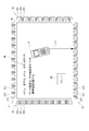
- the display control unit 41 displays various images on the display surface 20 of the display device 2. For example, as shown in FIG. 2, an operation method M1 for operating the touch panel device 1 and a menu button M2 are displayed.
- the object determination unit 42 scans the display surface 20 using the second infrared ray L2 from the first light emitting element 311 and the second light emitting element 321, and detects that the second infrared ray L2 is shielded, It is determined that an object is present on the display surface 20.
- the object identification unit 43 is on the display surface 20. It is determined that the object existing in the mobile phone P is the mobile phone P, and if the light is not received at all, it is determined that the object is the finger F.
- the data communication unit 44 performs data communication using the first infrared ray L1 with the mobile phone P existing on the display surface 20.
- the contents of the data communication are set in advance regardless of the location where the mobile phone P is present. For example, when the first infrared ray L1 from the mobile phone P is received by the first light receiving element 312, the data communication unit 44 acquires data transmitted using the first infrared ray L1, and performs predetermined processing on the data. Perform the process. In addition, the data communication unit 44 generates data to be transmitted to the mobile phone P as necessary, and transmits the data to the mobile phone P using the first infrared ray L1 from the first light emitting element 311.
- the presence position detection unit 45 uses the second infrared ray L2 from the first light emitting element 311 and the second light emitting element 321 to display the display surface. 20 is scanned. Then, the presence position of the finger F is detected based on the light shielding position of the second infrared ray L2.
- the presence position corresponding processing means 46 performs processing corresponding to the presence position of the finger F.
- the object determination unit 42 performs a light-shielding scan using the second infrared ray L2 in order to determine whether or not an object is present on the display surface 20 (step S1). . Then, the object determination unit 42 determines whether or not the shielding of the second infrared ray L2 has been detected (step S2), and repeats the processes of steps S1 and S2 until the shielding of the second infrared ray L2 is detected.
- the object determination unit 42 sequentially repeats Step S1 and Step S2 to sequentially arrange the first light emitting elements 311 arranged in a staggered pattern on the first side surface portion 21 and the second side surface portion 22 from the left side in FIG. One by one is driven to emit the second infrared ray L2. Then, based on the light reception signal from the first light receiving element 312 facing each first light emitting element 311, it is determined whether or not light shielding has been detected. When all the first light receiving elements 312 do not detect the light shielding, the second light emitting elements 321 arranged on the third side surface portion 23 and the fourth side surface portion 24 are sequentially driven one by one from the upper side in FIG.
- the second infrared ray L2 is emitted, and based on the light reception signal from the second light receiving element 322 facing each second light emitting element 321, it is determined whether or not the light shielding is detected.
- the first light receiving element 312 or the second light receiving element 322 outputs a light reception signal indicating that both the first infrared ray L1 and the second infrared ray L2 have been received. Based on only the light reception signal, the light shielding of the second infrared ray L2 is determined.
- the object determination means 42 stops light emission of the 2nd infrared rays L2, when light-shielding is detected in step S2 (step S3). For example, as shown in FIG. 4 or FIG. 5, when the light blocking of the second infrared ray L2 by the mobile phone P or the finger F is detected, the subsequent light emission of the first light emitting element 311 or the second light emitting element 321 is not performed.
- the object identification means 43 determines whether or not the object that shields the second infrared ray L2 is the mobile phone P (step S4). Specifically, the object identification unit 43 does not emit the second infrared ray L2 from the first light emitting element 311 and the second light emitting element 321, and the first infrared ray L1 from the first light receiving element 312 and the second light receiving element 322. It is determined whether or not the received light signal is acquired. Then, when the object identifying unit 43 determines that the object is the mobile phone P in step S4, the data communication unit 44 of the control device 4 performs data communication with the mobile phone P (step S5).
- the data communication unit 44 determines that the mobile phone P The data transmitted using the first infrared ray L1 is acquired and stored in the storage means. Further, as necessary, the data communication unit 44 emits the first infrared light L1 from the first light emitting elements 311 adjacent to the first light receiving element 312 that has received the first infrared light L1, as shown in FIG. Data is transmitted to the mobile phone P using the first infrared ray L1.
- the object determination means 42 performs the same processing as in steps S1 to S2, and as shown in FIG. 6, an object other than the mobile phone P, for example, a non-communication object such as a finger F exists on the display surface 20. It is determined whether or not (step S6). If it is determined in step S6 that there is no object other than the mobile phone P, it is determined whether or not the process is to be terminated by turning off the power (step S7). If the process is not to be terminated, step S1 is performed. Perform the process.
- the presence position detection unit 45 of the control device 4 detects the contact position of the non-communication object when the object identification unit 43 determines in step S4 that the object is not the mobile phone P, that is, a non-communication object. (Step S8).
- the presence position detection unit 45 also performs the process of step S8 when it is determined in step S6 that a non-communication object other than the mobile phone P is present.
- compatible process means 46 of the control apparatus 4 performs the process of step S7, after performing the process corresponding to a non-communication object (step S9).
- the presence position detection unit 45 determines that the object is the finger F without receiving the first infrared ray L1 from the mobile phone P by the first light receiving element 312,
- the second infrared rays L2 are sequentially emitted from all the first light emitting elements 311 and the second light emitting elements 321, and the second infrared rays L2 at the first light receiving elements 312 and the second light receiving elements 322 facing each other. Detects the light receiving state of. Then, based on the positions of the first light receiving element 312 and the second light receiving element 322 that have not received the second infrared ray L2, it is detected that the contact position of the finger F is on the menu button M2. Thereafter, the presence position corresponding processing means 46 controls the display control means 41 to display the menu screen on the display surface 20 as processing corresponding to the menu button M2.
- the touch panel device 1 determines that an object is present on the display surface 20, first, based on whether or not the first infrared ray L1 from the mobile phone P is received, the object is the mobile phone P. Determine whether or not. And if it is judged that it is the mobile telephone P, the data communication using the 1st infrared rays L1 will be performed between the said mobile telephones P. On the other hand, if it is determined that the finger F is not the mobile phone P, processing corresponding to the contact position of the finger F is performed.
- the user saves the data to be input to the touch panel device 1 in the mobile phone P in advance, and the first infrared ray L1 is simply obtained by placing the mobile phone P in the infrared communication mode on the display surface 20.
- Data communication using can be started, and data can be input to the touch panel device 1 by the data communication. Therefore, the data input operation with the finger F is not required, the labor of the input operation is saved, and erroneous data input can be prevented.
- the code data of the touch panel device 1 is stored by the mobile phone P
- the code transmitted from the touch panel device 1 by data communication can be obtained simply by placing the mobile phone P in the infrared communication mode on the display surface 20. Data can be stored in the mobile phone P.
- the touch panel device 1 detects the contact position of the finger F and performs processing corresponding to the detection position. For this reason, the touch panel device 1 can perform various processes corresponding to the contact position of the display surface 20 as in the conventional touch panel device.
- An element 312 and a second light receiving element 322 are provided.
- the first infrared ray L1 is applied as a wireless medium used for data communication between the touch panel device 1 and the mobile phone P
- the second infrared ray L2 is applied as a wireless medium used for contact position detection.
- the first light emitting element 311, the second light emitting element 321, the first light receiving element 312, and the second light receiving element 322 used for contact position detection can also be used for data communication, and a wireless medium other than infrared light for data communication The number of parts can be reduced as compared with the case of applying.
- a plurality of the first light emitting elements 311 and the first light receiving elements 312 are provided on the first side surface portion 21 and the second side surface portion 22 respectively, and the second light emitting elements 321 and the second light receiving elements 322 are provided on the first side.
- a plurality of three side surface portions 23 and a plurality of fourth side surface portions 24 are provided.
- the display control unit 41 displays an image as shown in FIG. Specifically, an operation method M11, a menu button M2, a coupon area M13 for transmitting a coupon of a predetermined store from the touch panel device 1 to the mobile phone P, and a map showing an access method to the store are displayed on the touch panel device. A map area M14 for transmission from 1 to the mobile phone P is displayed.
- the control device 4 performs the processing from step S1 to step S4.
- the data communication unit 44 controls the presence position detection unit 45 to detect the presence position of the mobile phone P (Ste S21).
- the data communication means 44 performs data communication corresponding to the location of the mobile phone P (step S22), and performs the process of step S6.
- the detection of the presence position in step S21 is the same as the process in step S8.
- the control device 4 detects that the mobile phone P in the infrared communication mode exists on the display surface 20 using the second infrared ray L2, as shown in FIG. 11, as shown in FIG. Based on the light receiving state of the first infrared ray L1 from the mobile phone P, it is determined that the object on the display surface 20 is the mobile phone P. Then, the data communication unit 44 controls the presence position detection unit 45 to perform the presence position detection process of the mobile phone P using the second infrared ray L2, as shown in FIG. Thereafter, the data communication means 44 determines that the location of the mobile phone P is on the coupon area M13 and, as shown in FIG.
- the first infrared ray L1 is emitted from the one light emitting element 311 and the coupon is transmitted to the mobile phone P using the first infrared ray L1.
- the data communication unit 44 transmits the map to the mobile phone P using the first infrared ray L1 from the first light emitting element 311 when the location of the mobile phone P is on the map area M14. .
- the present invention is not limited to the first and second embodiments described above, but includes modifications and improvements as long as the object of the present invention can be achieved. That is, any configuration such as a capacitance method or an electromagnetic induction method may be used as a configuration for detecting the presence position. Moreover, it is good also as a structure which performs the data communication by Bluetooth. Further, the first light emitting element 311 may be disposed only on the first side surface portion 21, and the first light receiving element 312 may be disposed only on the second side surface portion 22. In addition, infrared rays having the same wavelength band may be applied as a wireless medium used for data communication and a wireless medium used for detecting that an object is present on the display surface 20 and detecting a presence position.
- the communication device may be a PDA (Personal Digital Assistant), a camera, a clock, a content playback device, a dedicated pen, etc. each having a communication function.
- the touch panel device 1 may be used as a computer display device or may be installed on a wall. Furthermore, the touch panel device 1 may be used for displaying business information or information in a vehicle, or may be used for operating an electronic device.
Landscapes
- Engineering & Computer Science (AREA)
- General Engineering & Computer Science (AREA)
- Theoretical Computer Science (AREA)
- Human Computer Interaction (AREA)
- Physics & Mathematics (AREA)
- General Physics & Mathematics (AREA)
- Position Input By Displaying (AREA)
- Telephone Function (AREA)
Abstract
タッチパネル装置(1)は、表示面上に物体が存在しているか否かを判定する物体判定手段(42)と、携帯電話からの第1赤外線を受信する第1受光素子および第2受光素子と、物体の存在位置を検出する存在位置検出手段(45)と、第1受光素子および第2受光素子で前記第1赤外線を受光した場合に、前記物体が携帯電話であると判断し、前記第1赤外線を受信しない場合に、前記物体が携帯電話でないと判断する物体識別手段(43)と、前記物体が携帯電話であると判断されると、当該携帯電話との間で第1赤外線を用いたデータ通信を行うデータ通信手段(44)と、前記物体が携帯電話でないと判断されると、存在位置検出手段(45)で検出した存在位置に対応する処理を行う存在位置対応処理手段(46)と、を備える。
Description
本発明は、タッチパネル装置、および、これを用いた情報処理方法に関する。
従来、表示面の接触位置または近接位置に対応する処理を行うタッチパネル装置が知られている(例えば、特許文献1,2参照)。このようなタッチパネル装置は、表示面の画像を切り替えることで、多種の処理を行うことができることから、様々なサービスの提供に用いられている。
特許文献1の構成では、発光素子の配列間隔と受光素子の配列間隔とを異ならせ、発光素子から受光素子に向けて、所定の指向角度で光ビームを発光する。そして、光ビームの斜め方向の成分が受光素子で受光されなかった場合に、この受光素子の座標位置と発光素子の座標位置とを、座標位置マップに照合させることで、光ビームが遮蔽された座標位置を割り出している。
特許文献2の構成では、赤外線が照射された物体のシルエットを撮影して、この撮影したシルエットに基づいて、タッチ操作するための指先か否かを判断する。そして、指先であると判定した場合に、この指先がタッチしている位置に対応する処理を行っている。
特許文献2の構成では、赤外線が照射された物体のシルエットを撮影して、この撮影したシルエットに基づいて、タッチ操作するための指先か否かを判断する。そして、指先であると判定した場合に、この指先がタッチしている位置に対応する処理を行っている。
しかしながら、特許文献1,2に記載のようなタッチパネル装置を用いたサービスの提供を受けるために、ユーザが氏名や住所などのデータを入力する場合、指やペンなどを用いた操作が必要となり、入力操作に手間がかかったり、誤ったデータを入力してしまうおそれがある。また、タッチパネル装置に表示されたQRコードやバーコード(以下、単に、コードと言う)を介してサービスが提供される場合、通信機器である携帯電話でコードを撮影する必要があり、撮影操作に手間がかかってしまうおそれがある。
本発明は、表示面の接触位置または近接位置に対応する多種の処理を行うことが可能であるとともに、データを容易にかつ正確に交換可能なタッチパネル装置、および、これを用いた情報処理方法を提供することを1つの目的とする。
本発明のタッチパネル装置は、表示面に接触または近接した物体の位置に対応する処理を行うタッチパネル装置であって、前記表示面に物体が接触または近接したか否かを判定する物体判定手段と、通信機器からの無線媒体を受信する無線媒体受信手段と、前記物体の接触位置または近接位置を存在位置として検出する存在位置検出手段と、前記無線媒体受信手段で無線媒体を受信した場合に、前記物体が通信機器であると判断し、前記無線媒体を受信しない場合に、前記物体が通信機器でないと判断する物体識別手段と、前記物体識別手段で前記物体が通信機器であると判断されると、当該通信機器との間で無線媒体を用いたデータ通信を行うデータ通信手段と、前記物体識別手段で前記物体が通信機器でないと判断されると、前記存在位置検出手段で検出した存在位置に対応する処理を行う存在位置対応処理手段と、を備えることを特徴とする。
本発明のタッチパネル装置を用いた情報処理方法は、表示面に接触または近接した物体の位置に対応する処理を行うタッチパネル装置を用いた情報処理方法であって、前記表示面に物体が接触または近接したか否かを判定する工程と、通信機器からの無線媒体を受信した場合に、前記物体が通信機器であると判断し、前記無線媒体を受信しない場合に、前記物体が通信機器でないと判断する工程と、前記物体が通信機器であると判断されると、当該通信機器との間で無線媒体を用いたデータ通信を行う工程と、前記物体が通信機器でないと判断されると、前記物体の接触位置または近接位置を存在位置として検出し、この検出した存在位置に対応する処理を行う工程と、を実施することを特徴とする。
[第1実施形態]
まず、本発明の第1実施形態について図面に基づいて説明する。
{タッチパネル装置の構成}
図1において、タッチパネル装置1は、表示面20が上を向くテーブル型のものである。このタッチパネル装置1は、通信機器以外の物体(以下、非通信物体という)が表示面20に接触または近接(以下において、物体が表示面20に接触または近接している状態をまとめて「表示面20上に存在」と表現する場合がある)した場合、当該接触位置または近接位置(以下において、接触位置または近接位置をまとめて「存在位置」と表現する場合がある)に対応する処理をする。また、タッチパネル装置1は、通信機器が表示面20に載置された場合、当該通信機器との間でデータ通信を行う。
そして、タッチパネル装置1は、図1に示すように、表示装置2と、赤外線発光受光部3と、制御装置4(図3参照)とを備える。
まず、本発明の第1実施形態について図面に基づいて説明する。
{タッチパネル装置の構成}
図1において、タッチパネル装置1は、表示面20が上を向くテーブル型のものである。このタッチパネル装置1は、通信機器以外の物体(以下、非通信物体という)が表示面20に接触または近接(以下において、物体が表示面20に接触または近接している状態をまとめて「表示面20上に存在」と表現する場合がある)した場合、当該接触位置または近接位置(以下において、接触位置または近接位置をまとめて「存在位置」と表現する場合がある)に対応する処理をする。また、タッチパネル装置1は、通信機器が表示面20に載置された場合、当該通信機器との間でデータ通信を行う。
そして、タッチパネル装置1は、図1に示すように、表示装置2と、赤外線発光受光部3と、制御装置4(図3参照)とを備える。
なお、第1実施形態および後述する第2実施形態では、非通信物体として、人間の指Fを例示し、通信機器として、携帯電話Pを例示して説明する。また、データ通信に用いる無線媒体として、第1赤外線L1を例示し、指Fや携帯電話P(以下において、指Fと携帯電話Pとをまとめて「物体」と表現する場合がある)が表示面20上に存在していることの検出および存在位置の検出に用いる構成として、第1赤外線L1と波長帯域が異なる第2赤外線L2を用いた構成を例示して説明する。また、データ通信として、「OBEX IrDA」を例示して説明する。
表示装置2は、タッチパネル面である四角形状の表示面20を備える。この表示装置2は、第1側面部21と、第2側面部22と、第3側面部23と、第4側面部24とから構成される四角形状の枠体25内に収容されている。
赤外線発光受光部3は、第1発光受光部31と、第2発光受光部32とを備える。
第1発光受光部31は、図1および図2に示すように、それぞれ複数の第1発光素子311および第1受光素子312を備える。第1発光素子311、および、後述する第2発光素子321は、第1赤外線L1および第2赤外線L2を発光可能な赤外線LED(Light-Emitting Diode)である。また、第1受光素子312、および、後述する第2受光素子322は、第1赤外線L1および第2赤外線L2を受光可能な赤外線受光素子である。
第1発光素子311および第1受光素子312は、第1側面部21の左右方向および第2側面部22の左右方向に沿って、交互に、かつ、第1発光素子311の光軸上に第1受光素子312が配置されるように設けられている。すなわち、第1発光素子311および第1受光素子312は、第1側面部21と第2側面部22とに千鳥状に配置されている。
第1発光受光部31は、図1および図2に示すように、それぞれ複数の第1発光素子311および第1受光素子312を備える。第1発光素子311、および、後述する第2発光素子321は、第1赤外線L1および第2赤外線L2を発光可能な赤外線LED(Light-Emitting Diode)である。また、第1受光素子312、および、後述する第2受光素子322は、第1赤外線L1および第2赤外線L2を受光可能な赤外線受光素子である。
第1発光素子311および第1受光素子312は、第1側面部21の左右方向および第2側面部22の左右方向に沿って、交互に、かつ、第1発光素子311の光軸上に第1受光素子312が配置されるように設けられている。すなわち、第1発光素子311および第1受光素子312は、第1側面部21と第2側面部22とに千鳥状に配置されている。
第2発光受光部32は、第1発光素子311および第1受光素子312と同様に、第3側面部23と第4側面部24とに千鳥状に配置された、それぞれ複数の第2発光素子321および第2受光素子322を備える。
なお、第1受光素子312および第2受光素子322は、本発明の無線媒体受信手段として機能する。また、図2および当該図2と同様の図において、ドットが入っている図形は、第1受光素子312および第2受光素子322を表し、ドットが入っていない図形は、第1発光素子311および第2発光素子321を表す。
なお、第1受光素子312および第2受光素子322は、本発明の無線媒体受信手段として機能する。また、図2および当該図2と同様の図において、ドットが入っている図形は、第1受光素子312および第2受光素子322を表し、ドットが入っていない図形は、第1発光素子311および第2発光素子321を表す。
そして、第1発光素子311および第2発光素子321は、制御装置4の制御により、表示面20と平行に第1赤外線L1(図8参照)あるいは第2赤外線L2を発光する。第1受光素子312および第2受光素子322は、第1赤外線L1あるいは第2赤外線L2を受光すると、この受光量に対応する受光信号を制御装置4に出力する。
図3に示すように、制御装置4は、図示しない記憶手段に記憶されたプログラムおよびデータをCPU(Central Processing Unit)が処理することにより構成される、表示制御手段41と、物体判定手段42と、物体識別手段43と、データ通信手段44と、存在位置検出手段45と、存在位置対応処理手段46とを備える。
表示制御手段41は、表示装置2の表示面20に各種画像を表示させる。例えば、図2に示すように、タッチパネル装置1の操作のための操作方法M1や、メニューボタンM2を表示させる。
物体判定手段42は、第1発光素子311および第2発光素子321からの第2赤外線L2を用いて表示面20上を走査して、当該第2赤外線L2が遮光されていることを検出すると、表示面20上に物体が存在していると判定する。
物体識別手段43は、第1受光素子312と第2受光素子322とのうちの少なくともいずれか1つで、携帯電話Pで発光された第1赤外線L1が受光されている場合、表示面20上に存在している物体が携帯電話Pであると判断し、全てで受光されていない場合、物体が指Fであると判断する。
物体判定手段42は、第1発光素子311および第2発光素子321からの第2赤外線L2を用いて表示面20上を走査して、当該第2赤外線L2が遮光されていることを検出すると、表示面20上に物体が存在していると判定する。
物体識別手段43は、第1受光素子312と第2受光素子322とのうちの少なくともいずれか1つで、携帯電話Pで発光された第1赤外線L1が受光されている場合、表示面20上に存在している物体が携帯電話Pであると判断し、全てで受光されていない場合、物体が指Fであると判断する。
データ通信手段44は、表示面20上に存在している携帯電話Pとの間で、第1赤外線L1を用いたデータ通信を行う。なお、このデータ通信の内容は、携帯電話Pの存在位置によらず、予め設定されている。
例えば、データ通信手段44は、携帯電話Pからの第1赤外線L1が第1受光素子312で受光された場合、当該第1赤外線L1を利用して送信されたデータを取得し、当該データに対する所定の処理を行う。また、データ通信手段44は、必要に応じて、携帯電話Pへ送信するデータを生成し、第1発光素子311からの第1赤外線L1を利用して、当該データを携帯電話Pへ送信する。
存在位置検出手段45は、表示面20上に存在している物体が指Fであると判断されると、第1発光素子311および第2発光素子321からの第2赤外線L2を用いて表示面20上を走査する。そして、当該第2赤外線L2の遮光位置に基づいて、指Fの存在位置を検出する。
存在位置対応処理手段46は、指Fの存在位置に対応する処理を行う。
例えば、データ通信手段44は、携帯電話Pからの第1赤外線L1が第1受光素子312で受光された場合、当該第1赤外線L1を利用して送信されたデータを取得し、当該データに対する所定の処理を行う。また、データ通信手段44は、必要に応じて、携帯電話Pへ送信するデータを生成し、第1発光素子311からの第1赤外線L1を利用して、当該データを携帯電話Pへ送信する。
存在位置検出手段45は、表示面20上に存在している物体が指Fであると判断されると、第1発光素子311および第2発光素子321からの第2赤外線L2を用いて表示面20上を走査する。そして、当該第2赤外線L2の遮光位置に基づいて、指Fの存在位置を検出する。
存在位置対応処理手段46は、指Fの存在位置に対応する処理を行う。
{タッチパネル装置の作用}
次に、タッチパネル装置1の作用を説明する。
タッチパネル装置1を構成する制御装置4の表示制御手段41は、例えば、電源がオンされたことを検出すると、図2に示すような画像を表示面20で表示させる。
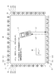
タッチパネル装置1のユーザは、表示面20の表示に基づいて、タッチパネル装置1と携帯電話Pとの間でのデータ通信を行いたい場合には、携帯電話Pを赤外線通信モードに設定して、図4に示すように、データ通信に用いる第1赤外線L1を携帯電話Pから発光させる。一方で、メニュー画面を表示させたい場合には、図5に示すように、指FでメニューボタンM2をタッチする。
次に、タッチパネル装置1の作用を説明する。
タッチパネル装置1を構成する制御装置4の表示制御手段41は、例えば、電源がオンされたことを検出すると、図2に示すような画像を表示面20で表示させる。
タッチパネル装置1のユーザは、表示面20の表示に基づいて、タッチパネル装置1と携帯電話Pとの間でのデータ通信を行いたい場合には、携帯電話Pを赤外線通信モードに設定して、図4に示すように、データ通信に用いる第1赤外線L1を携帯電話Pから発光させる。一方で、メニュー画面を表示させたい場合には、図5に示すように、指FでメニューボタンM2をタッチする。
この後、物体判定手段42は、図6に示すように、表示面20上に物体が存在しているか否かを判定するために、第2赤外線L2を用いた遮光スキャンを行う(ステップS1)。そして、物体判定手段42は、第2赤外線L2の遮光を検出したか否かを判断して(ステップS2)、第2赤外線L2の遮光を検出するまで、ステップS1およびステップS2の処理を繰り返す。
具体的に、物体判定手段42は、ステップS1およびステップS2の繰り返しにより、第1側面部21および第2側面部22に千鳥状に配置された第1発光素子311を、図2における左側から順次1つずつ駆動して第2赤外線L2を発光させる。そして、各第1発光素子311に対向する第1受光素子312からの受光信号に基づいて、遮光を検出したか否かを判断する。
全ての第1受光素子312で遮光を検出しなかった場合には、第3側面部23および第4側面部24に配置された第2発光素子321を、図2における上側から順次1つずつ駆動して第2赤外線L2を発光させ、各第2発光素子321に対向する第2受光素子322からの受光信号に基づいて、遮光を検出したか否かを判断する。
なお、第1受光素子312あるいは第2受光素子322から、第1赤外線L1および第2赤外線L2の両方を受光した旨の受光信号が出力されるが、物体判定手段42は、第2赤外線L2の受光信号のみに基づいて、第2赤外線L2の遮光を判断する。
全ての第1受光素子312で遮光を検出しなかった場合には、第3側面部23および第4側面部24に配置された第2発光素子321を、図2における上側から順次1つずつ駆動して第2赤外線L2を発光させ、各第2発光素子321に対向する第2受光素子322からの受光信号に基づいて、遮光を検出したか否かを判断する。
なお、第1受光素子312あるいは第2受光素子322から、第1赤外線L1および第2赤外線L2の両方を受光した旨の受光信号が出力されるが、物体判定手段42は、第2赤外線L2の受光信号のみに基づいて、第2赤外線L2の遮光を判断する。
そして、物体判定手段42は、ステップS2において、遮光を検出した場合には、第2赤外線L2の発光を停止させる(ステップS3)。例えば、図4あるいは図5に示すように、携帯電話Pや指Fによる第2赤外線L2の遮光を検出すると、以後の第1発光素子311あるいは第2発光素子321の発光を行わない。
この後、物体識別手段43は、図6に示すように、第2赤外線L2を遮光した物体が携帯電話Pか否かを判断する(ステップS4)。具体的に、物体識別手段43は、第1発光素子311および第2発光素子321での第2赤外線L2の発光を行わずに、第1受光素子312および第2受光素子322から第1赤外線L1の受光信号を取得したか否かを判断する。
そして、制御装置4のデータ通信手段44は、ステップS4において、物体識別手段43で物体が携帯電話Pであると判断された場合、携帯電話Pとの間でデータ通信を行う(ステップS5)。
そして、制御装置4のデータ通信手段44は、ステップS4において、物体識別手段43で物体が携帯電話Pであると判断された場合、携帯電話Pとの間でデータ通信を行う(ステップS5)。
例えば、データ通信手段44は、図7に示すように、携帯電話Pからの第1赤外線L1が第1受光素子312で受光されて物体が携帯電話Pであると判断された場合、携帯電話Pから第1赤外線L1を利用して送信されたデータを取得して、記憶手段に記憶させる。また、必要に応じて、データ通信手段44は、図8に示すように、第1赤外線L1を受光した第1受光素子312の両隣の第1発光素子311から第1赤外線L1を発光させ、当該第1赤外線L1を利用してデータを携帯電話Pへ送信する。
この後、物体判定手段42は、ステップS1からステップS2と同様の処理を行い、図6に示すように、携帯電話P以外の物体、例えば指Fなどの非通信物体が表示面20上に存在しているか否かを判断する(ステップS6)。そして、ステップS6において、携帯電話P以外の物体が存在していないと判断した場合、電源オフにより処理を終了するか否かを判断し(ステップS7)、処理を終了しない場合には、ステップS1の処理を行う。
一方で、制御装置4の存在位置検出手段45は、ステップS4において、物体識別手段43で物体が携帯電話Pでない、すなわち非通信物体であると判断された場合、非通信物体の接触位置を検出する(ステップS8)。また、存在位置検出手段45は、ステップS6において、携帯電話P以外の非通信物体が存在していると判断された場合も、ステップS8の処理を行う。
そして、制御装置4の存在位置対応処理手段46は、非通信物体のに対応する処理をした後(ステップS9)、ステップS7の処理を行う。
そして、制御装置4の存在位置対応処理手段46は、非通信物体のに対応する処理をした後(ステップS9)、ステップS7の処理を行う。
例えば、存在位置検出手段45は、図9に示すように、携帯電話Pからの第1赤外線L1が第1受光素子312で受光されずに、物体が指Fであると判断された場合、図10に示すように、全ての第1発光素子311および第2発光素子321から第2赤外線L2を順次発光させ、それぞれに対向する第1受光素子312および第2受光素子322での第2赤外線L2の受光状態を検出する。そして、第2赤外線L2を受光しなかった第1受光素子312および第2受光素子322の位置に基づいて、指Fの接触位置がメニューボタンM2上であることを検出する。
この後、存在位置対応処理手段46は、メニューボタンM2に対応する処理として、表示制御手段41を制御して、メニュー画面を表示面20に表示させる。
この後、存在位置対応処理手段46は、メニューボタンM2に対応する処理として、表示制御手段41を制御して、メニュー画面を表示面20に表示させる。
{第1実施形態の作用効果}
上述したような第1実施形態では、以下のような作用効果を奏することができる。
(1)タッチパネル装置1は、表示面20上に物体が存在していると判定すると、まず、携帯電話Pからの第1赤外線L1を受信したか否かに基づいて、当該物体が携帯電話Pか否かを判断する。そして、携帯電話Pであると判断すると、当該携帯電話Pとの間で第1赤外線L1を用いたデータ通信を行う。一方で、携帯電話Pでなく指Fであると判断すると、指Fの接触位置に対応する処理を行う。
このため、ユーザは、タッチパネル装置1に入力するデータを予め携帯電話Pに保存しておき、赤外線通信モードの携帯電話Pを表示面20に載置するだけの簡単な方法で、第1赤外線L1を用いたデータ通信を開始して、当該データ通信によりタッチパネル装置1にデータを入力することができる。したがって、指Fによるデータの入力操作が不要となり、入力操作の手間が省け、データの誤入力も防止できる。また、タッチパネル装置1が有するコードのデータを携帯電話Pで保存する場合でも、赤外線通信モードの携帯電話Pを表示面20に載置するだけで、データ通信によりタッチパネル装置1から送信されるコードのデータを、携帯電話Pに保存することができる。したがって、コードの撮影操作が不要となる。
さらに、タッチパネル装置1は、表示面20上に存在している物体が携帯電話Pでなく指Fであると判断すると、指Fの接触位置を検出し、当該検出位置に対応する処理を行う。
このため、タッチパネル装置1は、従来のタッチパネル装置と同様に、表示面20の接触位置に対応する多種の処理を行うことができる。
上述したような第1実施形態では、以下のような作用効果を奏することができる。
(1)タッチパネル装置1は、表示面20上に物体が存在していると判定すると、まず、携帯電話Pからの第1赤外線L1を受信したか否かに基づいて、当該物体が携帯電話Pか否かを判断する。そして、携帯電話Pであると判断すると、当該携帯電話Pとの間で第1赤外線L1を用いたデータ通信を行う。一方で、携帯電話Pでなく指Fであると判断すると、指Fの接触位置に対応する処理を行う。
このため、ユーザは、タッチパネル装置1に入力するデータを予め携帯電話Pに保存しておき、赤外線通信モードの携帯電話Pを表示面20に載置するだけの簡単な方法で、第1赤外線L1を用いたデータ通信を開始して、当該データ通信によりタッチパネル装置1にデータを入力することができる。したがって、指Fによるデータの入力操作が不要となり、入力操作の手間が省け、データの誤入力も防止できる。また、タッチパネル装置1が有するコードのデータを携帯電話Pで保存する場合でも、赤外線通信モードの携帯電話Pを表示面20に載置するだけで、データ通信によりタッチパネル装置1から送信されるコードのデータを、携帯電話Pに保存することができる。したがって、コードの撮影操作が不要となる。
さらに、タッチパネル装置1は、表示面20上に存在している物体が携帯電話Pでなく指Fであると判断すると、指Fの接触位置を検出し、当該検出位置に対応する処理を行う。
このため、タッチパネル装置1は、従来のタッチパネル装置と同様に、表示面20の接触位置に対応する多種の処理を行うことができる。
(2)タッチパネル装置1に、第1赤外線L1および第2赤外線L2を発光可能な第1発光素子311および第2発光素子321と、第1赤外線L1および第2赤外線L2を受光可能な第1受光素子312および第2受光素子322とを設けている。さらに、タッチパネル装置1と携帯電話Pとの間でのデータ通信に用いる無線媒体として第1赤外線L1を適用し、接触位置検出に用いる無線媒体として第2赤外線L2を適用している。
このため、接触位置検出に用いる第1発光素子311、第2発光素子321、第1受光素子312、第2受光素子322を、データ通信にも用いることができ、データ通信に赤外線以外の無線媒体を適用する場合と比べて、部品点数の削減を図ることができる。
このため、接触位置検出に用いる第1発光素子311、第2発光素子321、第1受光素子312、第2受光素子322を、データ通信にも用いることができ、データ通信に赤外線以外の無線媒体を適用する場合と比べて、部品点数の削減を図ることができる。
(3)第1発光素子311と第1受光素子312とを、第1側面部21と第2側面部22とにそれぞれ複数ずつ設け、第2発光素子321と第2受光素子322とを、第3側面部23と第4側面部24とにそれぞれ複数ずつ設けている。
このため、携帯電話Pにおける第1赤外線L1の発光位置や受光位置が、第1側面部21、第2側面部22、第3側面部23、第4側面部24のいずれに対向する場合でも、当該第1赤外線L1を受光することができるとともに、タッチパネル装置1からの第1赤外線L1を携帯電話Pに受光させることができる。したがって、携帯電話Pの載置向きによらず、データ通信を行うことができる。
このため、携帯電話Pにおける第1赤外線L1の発光位置や受光位置が、第1側面部21、第2側面部22、第3側面部23、第4側面部24のいずれに対向する場合でも、当該第1赤外線L1を受光することができるとともに、タッチパネル装置1からの第1赤外線L1を携帯電話Pに受光させることができる。したがって、携帯電話Pの載置向きによらず、データ通信を行うことができる。
[第2実施形態]
次に、本発明の第2実施形態について説明する。
第2実施形態と第1実施形態との違いは、データ通信の内容が、第1実施形態では、携帯電話Pの存在位置によらず予め設定されていたのに対して、第2実施形態では、携帯電話Pの存在位置によって異なっている点である。
なお、タッチパネル装置1の構成は、第1実施形態と同様のため、タッチパネル装置1の作用についてのみ説明する。また、作用の説明において、第1実施形態と同じ処理については、同一符号を付し説明を省略あるいは簡略にする。
次に、本発明の第2実施形態について説明する。
第2実施形態と第1実施形態との違いは、データ通信の内容が、第1実施形態では、携帯電話Pの存在位置によらず予め設定されていたのに対して、第2実施形態では、携帯電話Pの存在位置によって異なっている点である。
なお、タッチパネル装置1の構成は、第1実施形態と同様のため、タッチパネル装置1の作用についてのみ説明する。また、作用の説明において、第1実施形態と同じ処理については、同一符号を付し説明を省略あるいは簡略にする。
{タッチパネル装置の作用}
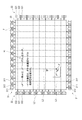
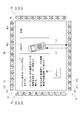
表示制御手段41は、電源がオンされると、図11に示すような画像を表示面20で表示させる。具体的に、操作方法M11と、メニューボタンM2と、所定の店舗のクーポンをタッチパネル装置1から携帯電話Pへ送信するためのクーポン領域M13と、当該店舗へのアクセス方法を示した地図をタッチパネル装置1から携帯電話Pへ送信するための地図領域M14とを表示させる。
表示制御手段41は、電源がオンされると、図11に示すような画像を表示面20で表示させる。具体的に、操作方法M11と、メニューボタンM2と、所定の店舗のクーポンをタッチパネル装置1から携帯電話Pへ送信するためのクーポン領域M13と、当該店舗へのアクセス方法を示した地図をタッチパネル装置1から携帯電話Pへ送信するための地図領域M14とを表示させる。
この後、制御装置4は、図12に示すように、ステップS1~ステップS4の処理を行う。そして、データ通信手段44は、ステップS4において、物体識別手段43で物体が携帯電話Pであると判断された場合、存在位置検出手段45を制御して、携帯電話Pの存在位置を検出させる(ステップS21)。この後、データ通信手段44は、携帯電話Pの存在位置に対応するデータ通信を行い(ステップS22)、ステップS6の処理を行う。なお、ステップS21での存在位置の検出は、ステップS8での処理と同様である。
例えば、制御装置4は、図11に示すように、第2赤外線L2を用いて、赤外線通信モードの携帯電話Pが表示面20上に存在していることを検出すると、図13に示すように、携帯電話Pからの第1赤外線L1の受光状態に基づいて、表示面20上の物体が携帯電話Pであると判断する。そして、データ通信手段44は、存在位置検出手段45を制御して、図14に示すように、第2赤外線L2を用いた携帯電話Pの存在位置検出処理を行わせる。
この後、データ通信手段44は、携帯電話Pの存在位置がクーポン領域M13上であると判断して、図15に示すように、第1赤外線L1を受光した第1受光素子312の両隣の第1発光素子311から第1赤外線L1を発光させ、当該第1赤外線L1を利用してクーポンを携帯電話Pへ送信する。一方で、データ通信手段44は、携帯電話Pの存在位置が地図領域M14上である場合には、第1発光素子311からの第1赤外線L1を利用して、地図を携帯電話Pへ送信する。
この後、データ通信手段44は、携帯電話Pの存在位置がクーポン領域M13上であると判断して、図15に示すように、第1赤外線L1を受光した第1受光素子312の両隣の第1発光素子311から第1赤外線L1を発光させ、当該第1赤外線L1を利用してクーポンを携帯電話Pへ送信する。一方で、データ通信手段44は、携帯電話Pの存在位置が地図領域M14上である場合には、第1発光素子311からの第1赤外線L1を利用して、地図を携帯電話Pへ送信する。
{第2実施形態の作用効果}
上述したような第2実施形態では、上述の第1実施形態と同様の作用効果に加えて、以下のような作用効果を奏することができる。
(4)タッチパネル装置1は、表示面20上に携帯電話Pが存在していることを検出すると、当該携帯電話Pの存在位置を検出し、当該存在位置に対応するデータ通信を行う。
このため、携帯電話Pとの間でのデータ通信の種類を増やすことができ、タッチパネル装置1の汎用性を向上できる。
上述したような第2実施形態では、上述の第1実施形態と同様の作用効果に加えて、以下のような作用効果を奏することができる。
(4)タッチパネル装置1は、表示面20上に携帯電話Pが存在していることを検出すると、当該携帯電話Pの存在位置を検出し、当該存在位置に対応するデータ通信を行う。
このため、携帯電話Pとの間でのデータ通信の種類を増やすことができ、タッチパネル装置1の汎用性を向上できる。
[変形例]
なお、本発明は前述の第1,第2実施形態に限定されるものではなく、本発明の目的を達成できる範囲での変形、改良などは本発明に含まれるものである。
すなわち、存在位置を検出する構成として、静電容量方式、電磁誘導方式などいずれの構成を用いてもよい。また、Bluetoothによるデータ通信を行う構成としてもよい。
さらに、第1発光素子311を第1側面部21のみに配置し、第1受光素子312を第2側面部22のみに配置してもよい。
また、データ通信に用いる無線媒体と、物体が表示面20上に存在していることの検出および存在位置の検出に用いる無線媒体として、同じ波長帯域の赤外線を適用してもよい。
また、通信機器としては、それぞれ通信機能を有する、PDA(Personal Digital Assistant)、カメラ、時計、コンテンツ再生装置、専用ペンなどであってもよい。
そして、タッチパネル装置1としては、コンピュータの表示装置として用いられるものであってもよいし、壁に設置されるものであってもよい。さらに、タッチパネル装置1としては、業務用インフォメーションや車内でのインフォメーションの表示に用いられるものであってもよいし、電子機器の操作に用いられるものであってもよい。
なお、本発明は前述の第1,第2実施形態に限定されるものではなく、本発明の目的を達成できる範囲での変形、改良などは本発明に含まれるものである。
すなわち、存在位置を検出する構成として、静電容量方式、電磁誘導方式などいずれの構成を用いてもよい。また、Bluetoothによるデータ通信を行う構成としてもよい。
さらに、第1発光素子311を第1側面部21のみに配置し、第1受光素子312を第2側面部22のみに配置してもよい。
また、データ通信に用いる無線媒体と、物体が表示面20上に存在していることの検出および存在位置の検出に用いる無線媒体として、同じ波長帯域の赤外線を適用してもよい。
また、通信機器としては、それぞれ通信機能を有する、PDA(Personal Digital Assistant)、カメラ、時計、コンテンツ再生装置、専用ペンなどであってもよい。
そして、タッチパネル装置1としては、コンピュータの表示装置として用いられるものであってもよいし、壁に設置されるものであってもよい。さらに、タッチパネル装置1としては、業務用インフォメーションや車内でのインフォメーションの表示に用いられるものであってもよいし、電子機器の操作に用いられるものであってもよい。
1…タッチパネル装置
20…表示面
42…物体判定手段
43…物体識別手段
44…データ通信手段
45…存在位置検出手段
46…存在位置対応処理手段
311…第1発光素子
312…無線媒体受信手段としての第1受光素子
321…第2発光素子
322…無線媒体受信手段としての第2受光素子
L1…第1赤外線
L2…第2赤外線
P…通信機器としての携帯電話
20…表示面
42…物体判定手段
43…物体識別手段
44…データ通信手段
45…存在位置検出手段
46…存在位置対応処理手段
311…第1発光素子
312…無線媒体受信手段としての第1受光素子
321…第2発光素子
322…無線媒体受信手段としての第2受光素子
L1…第1赤外線
L2…第2赤外線
P…通信機器としての携帯電話
Claims (6)
- 表示面に接触または近接した物体の位置に対応する処理を行うタッチパネル装置であって、
前記表示面に物体が接触または近接したか否かを判定する物体判定手段と、
通信機器からの無線媒体を受信する無線媒体受信手段と、
前記物体の接触位置または近接位置を存在位置として検出する存在位置検出手段と、
前記無線媒体受信手段で無線媒体を受信した場合に、前記物体が通信機器であると判断し、前記無線媒体を受信しない場合に、前記物体が通信機器でないと判断する物体識別手段と、
前記物体識別手段で前記物体が通信機器であると判断されると、当該通信機器との間で無線媒体を用いたデータ通信を行うデータ通信手段と、
前記物体識別手段で前記物体が通信機器でないと判断されると、前記存在位置検出手段で検出した存在位置に対応する処理を行う存在位置対応処理手段と、
を備えることを特徴とするタッチパネル装置。 - 請求項1に記載のタッチパネル装置において、
前記表示面の外縁には、
所定の波長帯域の赤外線を、当該表示面の面方向に沿って発光可能な複数の発光素子と、
前記複数の発光素子とそれぞれ対向する位置に配置され、赤外線を受光可能な複数の受光素子と、が設けられ、
前記通信機器との間でのデータ通信に用いられる無線媒体は、赤外線であり、
前記受光素子は、前記無線媒体受信手段として機能し、
前記物体判定手段は、前記発光素子からの赤外線を用いて前記表示面上を走査して、少なくとも1つの受光素子で前記赤外線を受光していない場合に、前記表示面に物体が接触または近接していると判定し、
前記存在位置検出手段は、前記発光素子からの赤外線を用いて前記表示面上を走査して、前記赤外線を受光していない受光素子の配置位置に基づいて、前記物体の存在位置を検出し、
前記物体識別手段は、前記複数の発光素子から赤外線が発光されていないタイミングにおいて、前記通信機器からの赤外線を前記受光素子で受光した場合に、前記物体が通信機器であると判断する
ことを特徴とするタッチパネル装置。 - 請求項1に記載のタッチパネル装置において、
前記表示面の外縁には、
互いに波長帯域が異なる第1赤外線および第2赤外線を、当該表示面の面方向に沿って発光可能な複数の発光素子と、
前記複数の発光素子とそれぞれ対向する位置に配置され、第1赤外線および第2赤外線を受光可能な複数の受光素子と、が設けられ、
前記通信機器との間でのデータ通信に用いられる無線媒体は、第1赤外線であり、
前記受光素子は、前記無線媒体受信手段として機能し、
前記物体判定手段は、前記発光素子からの第2赤外線を用いて前記表示面上を走査して、少なくとも1つの受光素子で前記第2赤外線を受光していない場合に、前記表示面に物体が接触または近接していると判定し、
前記存在位置検出手段は、前記発光素子からの第2赤外線を用いて前記表示面上を走査して、前記第2赤外線を受光していない受光素子の配置位置に基づいて、前記物体の存在位置を検出し、
前記物体識別手段は、前記通信機器からの第1赤外線を前記受光素子で受光した場合に、前記物体が通信機器であると判断する
ことを特徴とするタッチパネル装置。 - 請求項2または請求項3に記載のタッチパネル装置において、
前記データ通信手段は、前記物体識別手段で前記物体が通信機器であると判断されると、前記存在位置検出手段に前記通信機器の存在位置を検出させ、前記存在位置検出手段で検出した存在位置に対応するデータ通信を行う
ことを特徴とするタッチパネル装置。 - 請求項2から請求項4のいずれかに記載のタッチパネル装置において、
前記表示面は、四角形状に形成され、
前記表示面の四角形状の各辺には、前記発光素子と前記受光素子とが、それぞれ少なくとも1つずつ配置されている
ことを特徴とするタッチパネル装置。 - 表示面に接触または近接した物体の位置に対応する処理を行うタッチパネル装置を用いた情報処理方法であって、
前記表示面に物体が接触または近接したか否かを判定する工程と、
通信機器からの無線媒体を受信した場合に、前記物体が通信機器であると判断し、前記無線媒体を受信しない場合に、前記物体が通信機器でないと判断する工程と、
前記物体が通信機器であると判断されると、当該通信機器との間で無線媒体を用いたデータ通信を行う工程と、
前記物体が通信機器でないと判断されると、前記物体の接触位置または近接位置を存在位置として検出し、この検出した存在位置に対応する処理を行う工程と、を実施する
ことを特徴とするタッチパネル装置を用いた情報処理方法。
Priority Applications (1)
| Application Number | Priority Date | Filing Date | Title |
|---|---|---|---|
| PCT/JP2011/059381 WO2012140772A1 (ja) | 2011-04-15 | 2011-04-15 | タッチパネル装置、および、これを用いた情報処理方法 |
Applications Claiming Priority (1)
| Application Number | Priority Date | Filing Date | Title |
|---|---|---|---|
| PCT/JP2011/059381 WO2012140772A1 (ja) | 2011-04-15 | 2011-04-15 | タッチパネル装置、および、これを用いた情報処理方法 |
Publications (1)
| Publication Number | Publication Date |
|---|---|
| WO2012140772A1 true WO2012140772A1 (ja) | 2012-10-18 |
Family
ID=47008974
Family Applications (1)
| Application Number | Title | Priority Date | Filing Date |
|---|---|---|---|
| PCT/JP2011/059381 Ceased WO2012140772A1 (ja) | 2011-04-15 | 2011-04-15 | タッチパネル装置、および、これを用いた情報処理方法 |
Country Status (1)
| Country | Link |
|---|---|
| WO (1) | WO2012140772A1 (ja) |
Cited By (3)
| Publication number | Priority date | Publication date | Assignee | Title |
|---|---|---|---|---|
| EP2897035A1 (en) * | 2014-01-15 | 2015-07-22 | Nokia Corporation | Dynamic threshold for local connectivity setup |
| WO2018145311A1 (zh) * | 2017-02-13 | 2018-08-16 | 深圳市欸阿技术有限公司 | 数据分享系统、智能终端、第一智能终端 |
| JP2019519057A (ja) * | 2016-06-24 | 2019-07-04 | エスケー テレコム カンパニー、リミテッド | テーブルトップディスプレイ装置及びその駆動方法 |
Citations (2)
| Publication number | Priority date | Publication date | Assignee | Title |
|---|---|---|---|---|
| JP2006197594A (ja) * | 2005-01-11 | 2006-07-27 | Samsung Electro Mech Co Ltd | データ通信遂行方法およびデータ通信遂行システム |
| JP2009253478A (ja) * | 2008-04-02 | 2009-10-29 | Sony Ericsson Mobilecommunications Japan Inc | 情報通信装置、情報通信装置の制御方法 |
-
2011
- 2011-04-15 WO PCT/JP2011/059381 patent/WO2012140772A1/ja not_active Ceased
Patent Citations (2)
| Publication number | Priority date | Publication date | Assignee | Title |
|---|---|---|---|---|
| JP2006197594A (ja) * | 2005-01-11 | 2006-07-27 | Samsung Electro Mech Co Ltd | データ通信遂行方法およびデータ通信遂行システム |
| JP2009253478A (ja) * | 2008-04-02 | 2009-10-29 | Sony Ericsson Mobilecommunications Japan Inc | 情報通信装置、情報通信装置の制御方法 |
Cited By (4)
| Publication number | Priority date | Publication date | Assignee | Title |
|---|---|---|---|---|
| EP2897035A1 (en) * | 2014-01-15 | 2015-07-22 | Nokia Corporation | Dynamic threshold for local connectivity setup |
| US9753562B2 (en) | 2014-01-15 | 2017-09-05 | Nokia Technologies Oy | Dynamic threshold for local connectivity setup |
| JP2019519057A (ja) * | 2016-06-24 | 2019-07-04 | エスケー テレコム カンパニー、リミテッド | テーブルトップディスプレイ装置及びその駆動方法 |
| WO2018145311A1 (zh) * | 2017-02-13 | 2018-08-16 | 深圳市欸阿技术有限公司 | 数据分享系统、智能终端、第一智能终端 |
Similar Documents
| Publication | Publication Date | Title |
|---|---|---|
| US11009978B2 (en) | OLED panel, OLED apparatus, fingerprint identification method and device thereof, and storage medium | |
| US8766766B2 (en) | Information processing apparatus, information processing system, information processing method, and program | |
| RU2688192C1 (ru) | Терминал, способ, аппарат и электронное устройство для идентификации касания | |
| US20180284944A1 (en) | Apparatus for contactlessly detecting indicated position on reproduced image | |
| US20090141008A1 (en) | Electronic Touch Screen Device Providing Signature Capture and Touch Activation | |
| CN102707827A (zh) | 用于对触摸屏进行校准的电子设备和方法 | |
| US20110308159A1 (en) | Apparatus for detecting coordinates, and display device, security device, and electronic blackboard including the same | |
| CN101673159A (zh) | 光触摸屏 | |
| US20150253932A1 (en) | Information processing apparatus, information processing system and information processing method | |
| WO2012140772A1 (ja) | タッチパネル装置、および、これを用いた情報処理方法 | |
| JP2016183922A (ja) | 距離画像取得装置及び距離画像取得方法 | |
| TWI423094B (zh) | 光學式觸控裝置及其運作方法 | |
| US20140327631A1 (en) | Touch screen panel display and touch key input system | |
| JP7468580B2 (ja) | 端末装置及びプログラム | |
| US20100073321A1 (en) | Display apparatus | |
| US8711126B2 (en) | Optical input device | |
| KR100860158B1 (ko) | 펜 형의 위치 입력 장치 | |
| JP4457163B1 (ja) | 表示装置 | |
| WO2013076824A1 (ja) | タッチパネル装置における情報処理方法、および、タッチパネル装置 | |
| US20180278763A1 (en) | Input device, image forming apparatus, and non-transitory computer readable medium | |
| JP7286612B2 (ja) | 操作検出装置及び操作検出方法 | |
| CN114444527A (zh) | 一种扫码识别方法、装置、设备及介质 | |
| JP2014063212A (ja) | タッチパネル装置 | |
| US10212294B2 (en) | Input device and non-transitory computer readable medium | |
| US10198129B2 (en) | Input device, image forming apparatus, and non-transitory computer readable medium |
Legal Events
| Date | Code | Title | Description |
|---|---|---|---|
| 121 | Ep: the epo has been informed by wipo that ep was designated in this application |
Ref document number: 11863337 Country of ref document: EP Kind code of ref document: A1 |
|
| NENP | Non-entry into the national phase |
Ref country code: DE |
|
| 122 | Ep: pct application non-entry in european phase |
Ref document number: 11863337 Country of ref document: EP Kind code of ref document: A1 |
|
| NENP | Non-entry into the national phase |
Ref country code: JP |